

Page 1

SERVICE MANUAL
MODEL: P-touch BB4
Page 2

SERVICE MANUAL
MODEL: P-touch BB4
Page 3

© Copyright Brother 2001
All rights reserved.
No part of this publication may be reproduced in any
form or by any means without permission in writing
from the publisher.
Specifications are subject to change without notice.
Page 4

PREFACE
This publication is a service manual covering the specifications, theory of operation,
disassembly/reassembly procedure, and troubleshooting of the Brother P-touch BB4. It
is intended for service personnel and other concerned persons to accurately and
quickly provide after-sale service for our P-touch BB4.
To perform appropriate maintenance so that the machine is always in best condition
for the customer, the service personnel must adequately understand and apply this
manual.
This manual is made up of four chapters and appendix.
CHAPTER I SPECIFICATIONS
CHAPTER II MECHANISMS
CHAPTER III ELECTRONICS
CHAPTER IV TROUBLESHOOTING
APPENDIX CIRCUIT DIAGRAM
Page 5

Chapter I.
SPECIFICATIONS
Page 6

CONTENTS
CHAPTER I. SPECIFICATIONS
1.1 MECHANICAL SPECIFICATIONS........................................................................................ I-1
1.1.1 External Appearance................................................................................................ I-1
1.1.2 Entry system ............................................................................................................ I-1
1.1.3 Display ..................................................................................................................... I-1
1.1.4 Printing Mechanism.................................................................................................. I-2
1.1.5 Tape Cassette.......................................................................................................... I-2
1.1.6 Tape Cutter.............................................................................................................. I-2
1.2 ELECTRONICS SPECIFICATIONS...................................................................................... I-5
1.2.1 Character Generator ................................................................................................ I-5
1.2.2 Power Supply........................................................................................................... I-5
Page 7
1.1 MECHANICAL SPECIFICATIONS
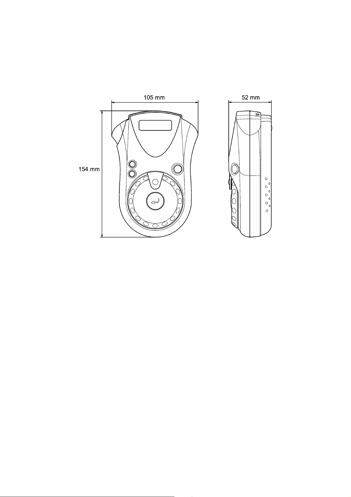
1.1.1 External Appearance
(1) Dimensions (W x D x H) 105 mm x 154 mm x 52 mm
(2) Weight
Machine proper Approx. 250 g
In package Approx. 500 g (incl. a tape cassette, excl. dry cells)
1.1.2 Entry system
(1) Rubber keypad 4 keys
(2) Dial 32 positions
1.1.3 Display
(1) Display type Liquid crystal display (LCD)
(2) Number of columns 8 columns x 1 row
(3) Number of indicators 4 (See Figure 1.1-2.)
Figure 1.1-1 External Appearance
(See Figure 1.1-2.)
I - 1
Page 8

1.1.4 Printing Mechanism
(1) Print system Direct thermal printing
(2) Print speed 7.5 mm/second (Typical)
(3) Print head
Type Thermal print head
Heat generator Consists of 64 heating elements vertically aligned
Size of a heating element 0.136 mm wide by 0.106 mm high
1.1.5 Tape Cassette
(1) Cassette Cartridge type
(2) Tape type Direct thermal print tape
(3) Tape size Width: 9, 12 mm
(4) Tape cassette packed with the machine Character color: Black
(Fixed print head and tape feeding mechanism)
Length: 8 m
Tape color: White
Tape width: 12 mm or 9 mm (EU)
Tape length: 4 m
1.1.6 Tape Cutter
(1) Tape cutting Manual cutting with the cutter lever
(2) Cutter unit User-replaceable
I - 2
Page 9
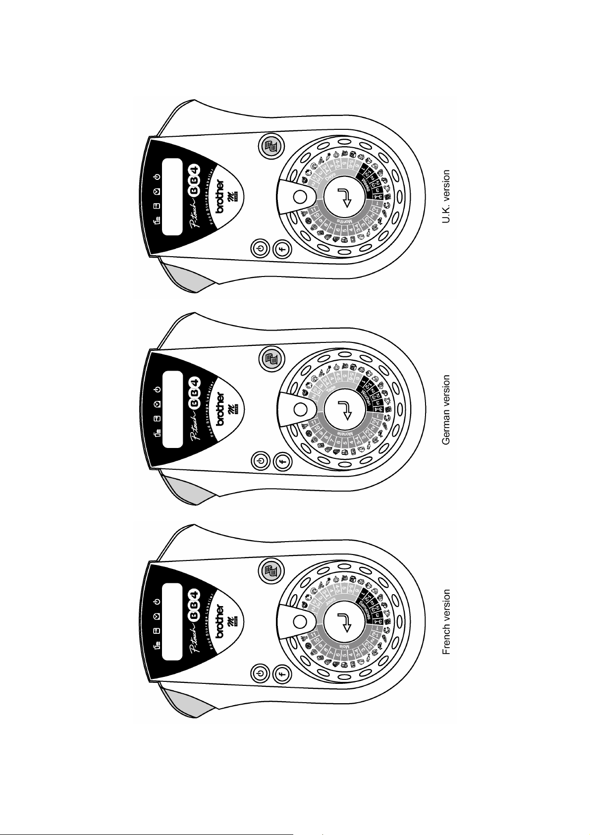
Figure 1.1-2 Key Arrangement (1)
I - 3
Page 10
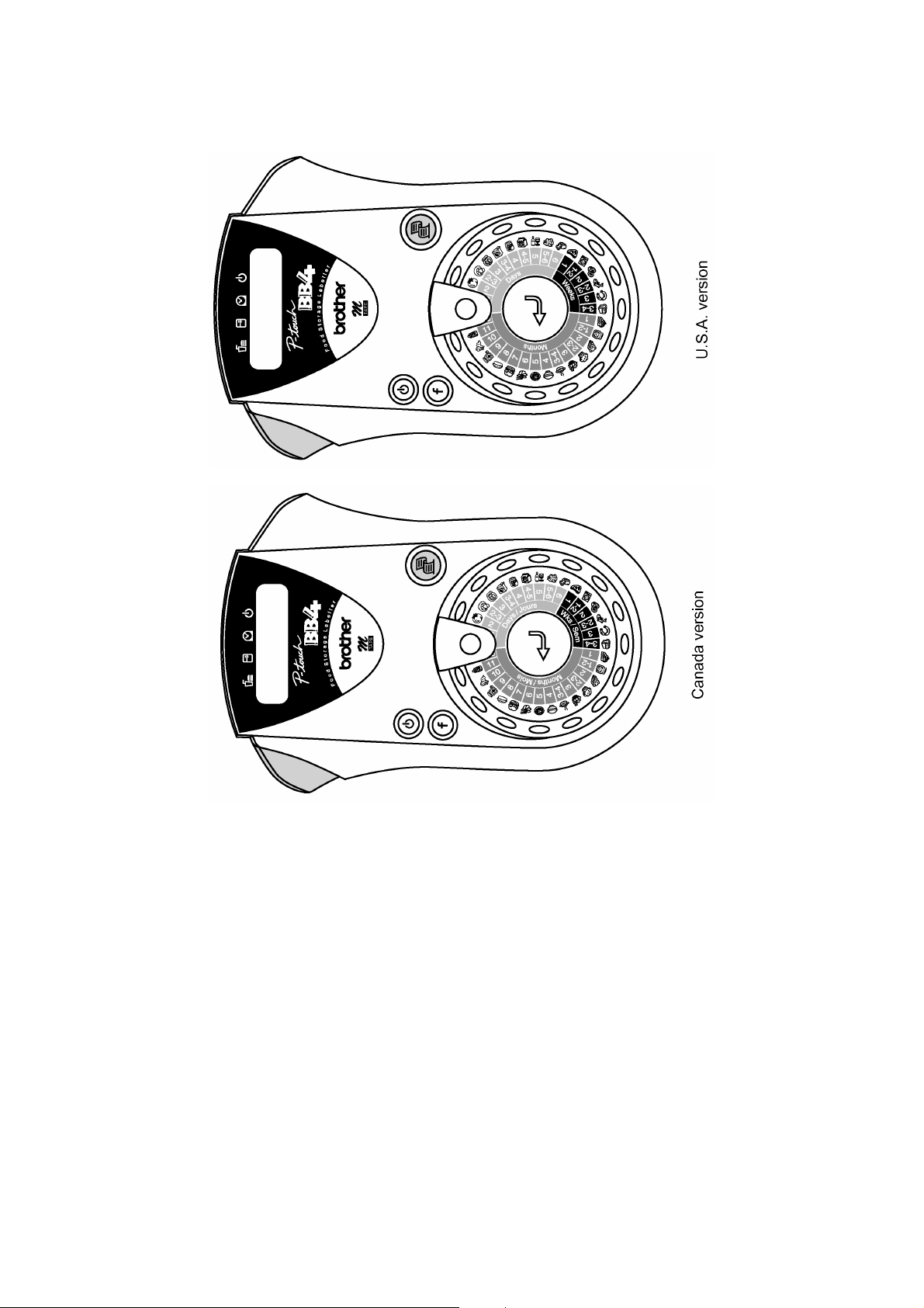
Figure 1.1-2 Key Arrangement (2)
I - 4
Page 11

1.2 ELECTRONICS SPECIFICATIONS
1.2.1 Character Generator
(1) No. of printable symbols 31
(2) Internal fonts HELSINKI
(3) Phrase memory capacity None
1.2.2 Power Supply
(1) Power supply Driven by 6 dry cells
(2) Battery type Alkaline dry cells (AM3/LR6)
(3) Service life of batteries Will last through one tape cassette, and then some
(at room temperature and normal humidity).
(4) Calendar clock (default) Yes (If the machine remains unused for approx. 1
minute with its power on, then the LCD shows the
calendar clock or goes off depending upon your
choice.)
(5) Low voltage indication
If the voltage drops below the following level:
in entry mode or
during printing
approx. 5.86V approx. 5.35V Display the "BATTERY" message.
approx. 5.35V approx. 4.94V
approx. 2.90V
in clock mode
Turn the LCD off. (The internal clock
remains on.)
Turn itself off. (The internal clock and
other settings will be reset.)
Then, the machine will:
I - 5
Page 12

Chapter II.
MECHANISMS
Page 13

CONTENTS
CHAPTER II. MECHANISMS
2.1 THEORY OF OPERATION.................................................................................................. II-1
2.1.1 Print Mechanism ..................................................................................................... II-1
2.1.2 Platen Setting & Retracting Mechanism .................................................................. II-2
2.1.3 Tape Feed Mechanism............................................................................................ II-3
2.1.4 Tape Cutter Mechanism.......................................................................................... II-4
2.1.5 Cutter Safety Lock Mechanism................................................................................ II-5
2.2 DISASSEMBLY & REASSEMBLY ....................................................................................... II-6
2.2.1 Disassembly Procedure .......................................................................................... II-7
[ 1 ] Removing the Cassette Cover, Dry Cells, Tape Cassette, and Cutter Unit.............. II-7
[ 2 ] Removing the Chassis ASSY.................................................................................. II-8
[ 3 ] Removing the Main PCB ....................................................................................... II-11
[ 4 ] Removing Battery Terminals P1 and P2................................................................ II-13
[ 5 ] Removing the Rubber 4 Key, Lens, Dial Sheet, Select Dial, Select Dial Claw,
and Enter Key ....................................................................................................... II-14
2.2.2 Reassembly Procedure......................................................................................... II-15
[ 1 ] Installing the Enter Key, Select Dial Claw, Select Dial, Dial Sheet, Lens, and
Rubber 4 Key ........................................................................................................ II-15
[ 2 ] Installing Battery Terminals P2 and P1.................................................................. II-17
[ 3 ] Installing the Main PCB......................................................................................... II-18
[ 4 ] Installing the Chassis ASSY.................................................................................. II-19
[ 5 ] Setting the Cutter Unit, Tape Cassette, Dry Cells, and Cassette Cover................. II-22
[ 6 ] Final Operation Check........................................................................................... II-23
[ 7 ] Inspection Mode.................................................................................................... II-24
Page 14
2.1 THEORY OF OPERATION
2.1.1 Print Mechanism
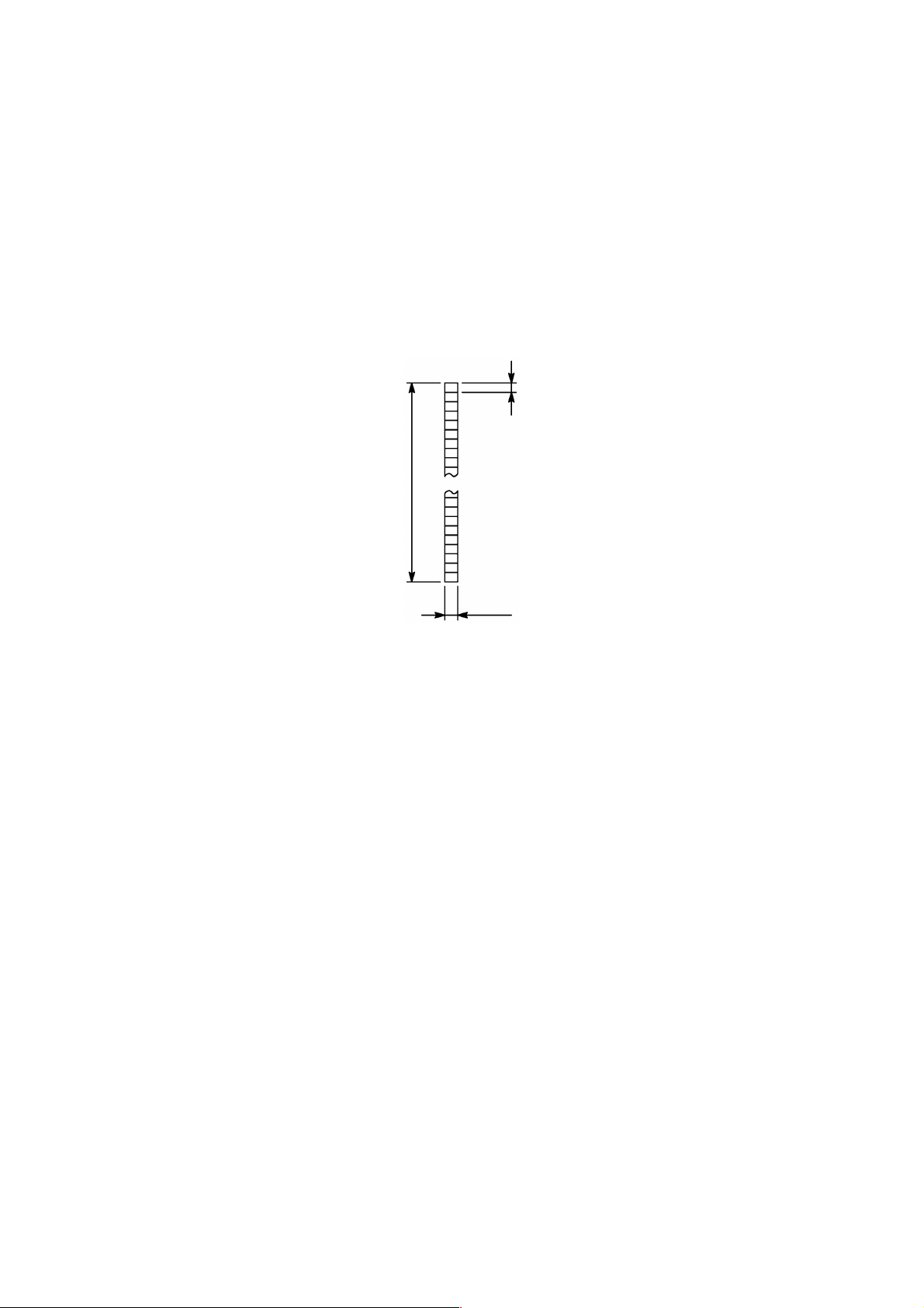
■■■■ Structure of Thermal Head
This machine uses direct thermal printing. The thermal print head has a heat generator
consisting of 64 heating elements which are vertically aligned as shown in Figure 2.1-1.
Each heating element is 0.136 mm wide by 0.106 mm high.
0.106 mm
6.784 mm
0.136 mm
Figure 2.1-1 Heat Generator of Thermal Head
Printing Process
When the cylindrical rubber platen is pressed against the thermal print head with the
thermal tape sandwiched inbetween, the CPU applies electric power to the selected ones
of those 64 heating elements.
The selected heating element(s) generates heat that dissolves the metal deposit layer of
the thermal tape so as to reveal the substrate layer, producing a dot on the tape. The tape
is advanced and the next heating cycle is repeated, thus forming a character on the tape.
Character Formation
While the drive motor (DC motor) feeds the tape by 0.106 mm for 13.8 ms, the thermal
head generates heat once. The feed amount of 0.106 mm is smaller than the width (0.136
mm) of the heating elements so that the heat generated at one heating cycle will overlap
with the next heating cycle. This forms a character having no gap between adjacent
printed dots.
II - 1
Page 15
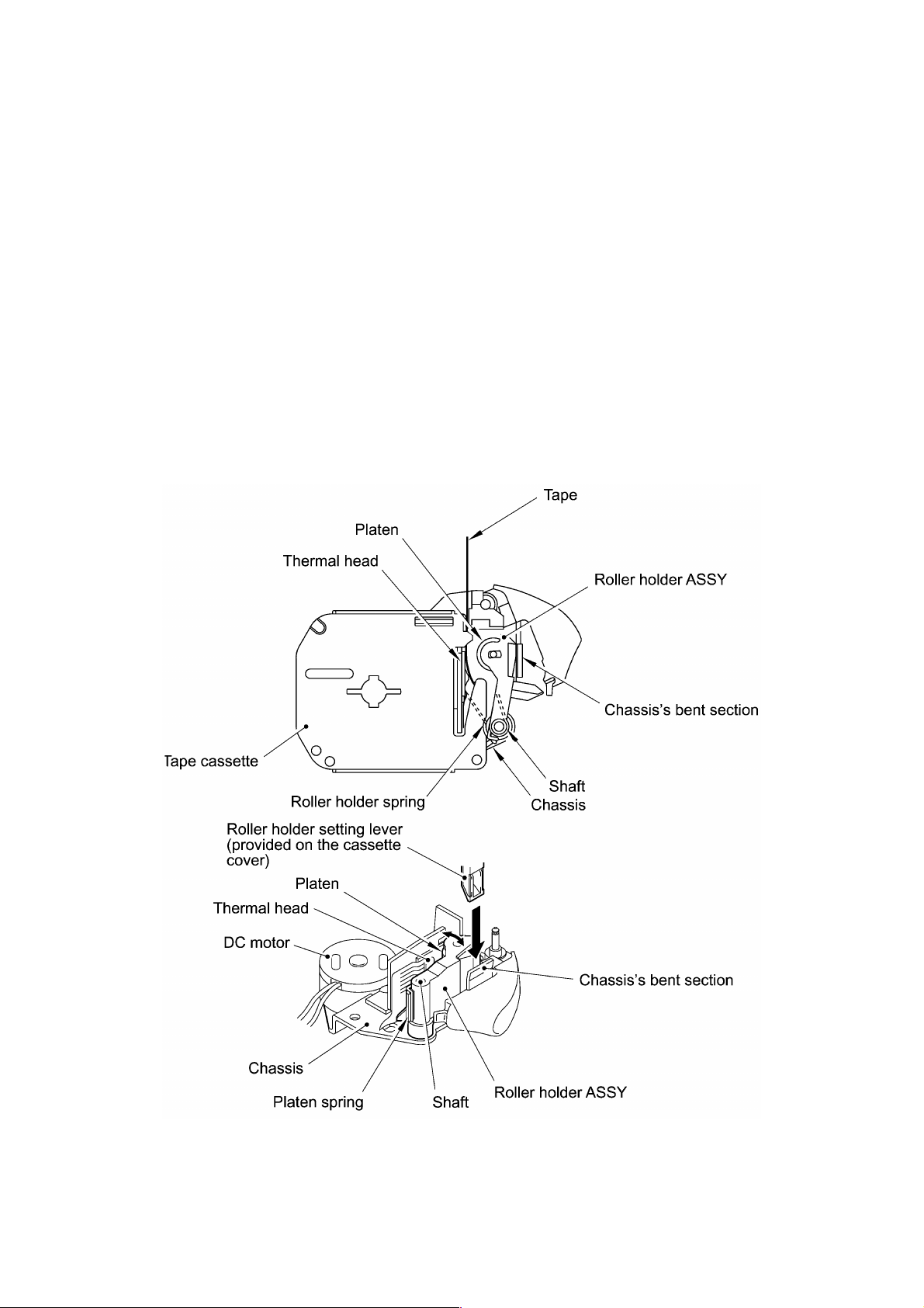
2.1.2 Platen Setting & Retracting Mechanism
This mechanism consists of the roller holder ASSY and the roller holder setting lever
(wedged lever) provided on the inside of the cassette cover.
The roller holder ASSY supports the platen so that the platen can move perpendicularly to
the thermal head and rotate freely.
Closing the cassette cover fits its roller holder setting lever into the slot between the roller
holder ASSY and the chassis's bent section. This pivots the roller holder ASSY around the
shaft provided on the chassis so as to press the roller holder ASSY against the thermal
head.
The platen is pressed perpendicularly against the thermal head with the tape sandwiched
inbetween under a uniform load by the platen spring. At the same time, the platen gear
becomes engaged with the drive gear of the gear train on the chassis (see Figure 2.1-3).
Opening the cassette cover pulls out its roller holder setting lever so that the roller holder
spring retracts the roller holder ASSY from the thermal head, providing you with enough
space to replace the tape cassette.
Figure 2.1-2 Platen Setting & Retracting Mechanism
II - 2
Page 16
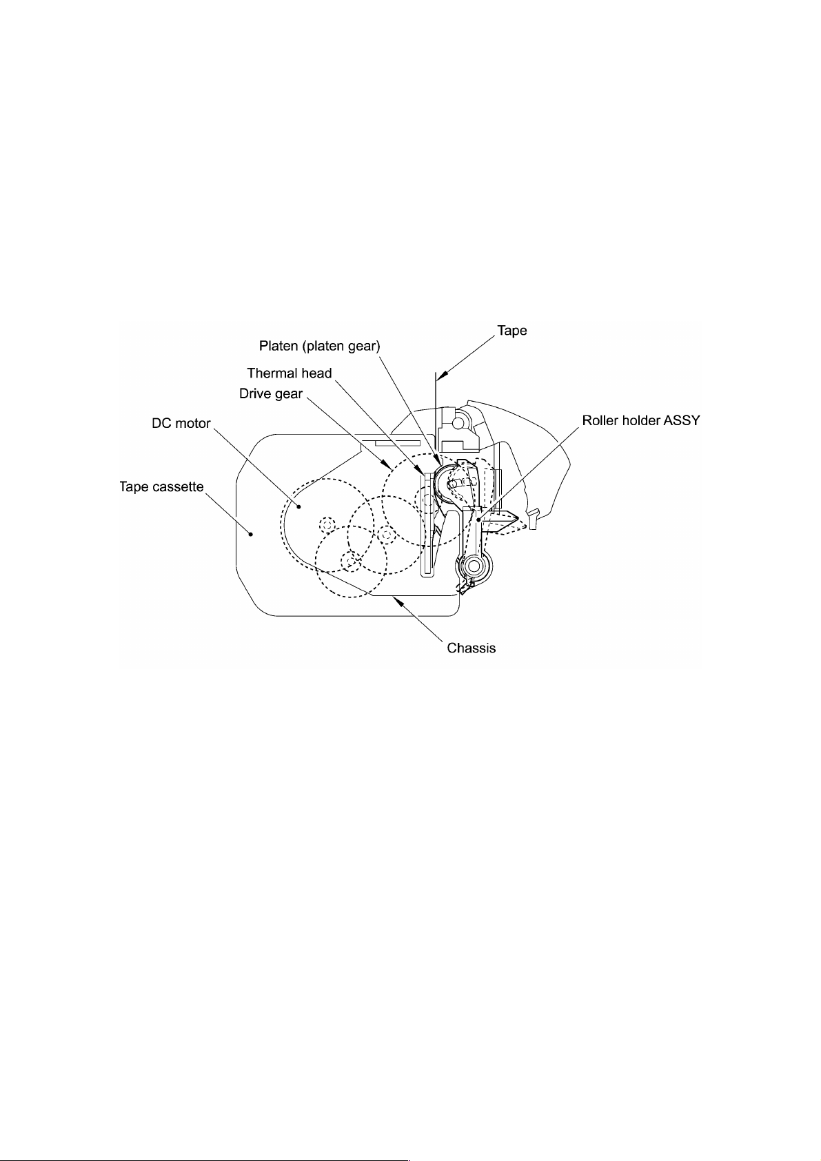
2.1.3 Tape Feed Mechanism
This mechanism consists of a DC motor, gear train and roller holder ASSY.
When you load a tape cassette and close the cassette cover, the platen and the thermal
head sandwich the tape inbetween and the platen gear becomes engaged with the gear
train, as described in Subsection 2.1.2.
As the DC motor rotates, the rotation is transmitted via the gear train to the platen gear.
Accordingly, the sandwiched tape will be advanced.
Figure 2.1-3 Tape Feed Mechanism
II - 3
Page 17
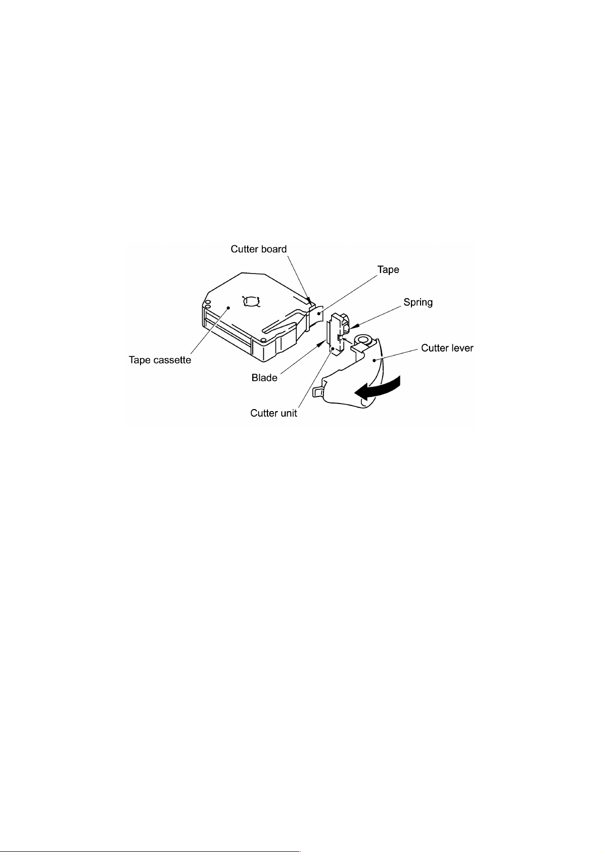
2.1.4 Tape Cutter Mechanism
The cutter mechanism consists of a cutter lever and a cutter unit in which a blade is
retracted by a spring.
Pressing the cutter lever pushes out the blade from the cutter unit. The blade presses the
printed tape against the cutter board of the tape cassette, cutting the tape coming through
the cutter unit and the cutter board.
When the cassette cover is opened and no tape cassette is loaded, the cutter safety
mechanism works to lock the cutter lever as described in Subsection 2.1.5.
Figure 2.1-4 Tape Cutter Mechanism
II - 4
Page 18
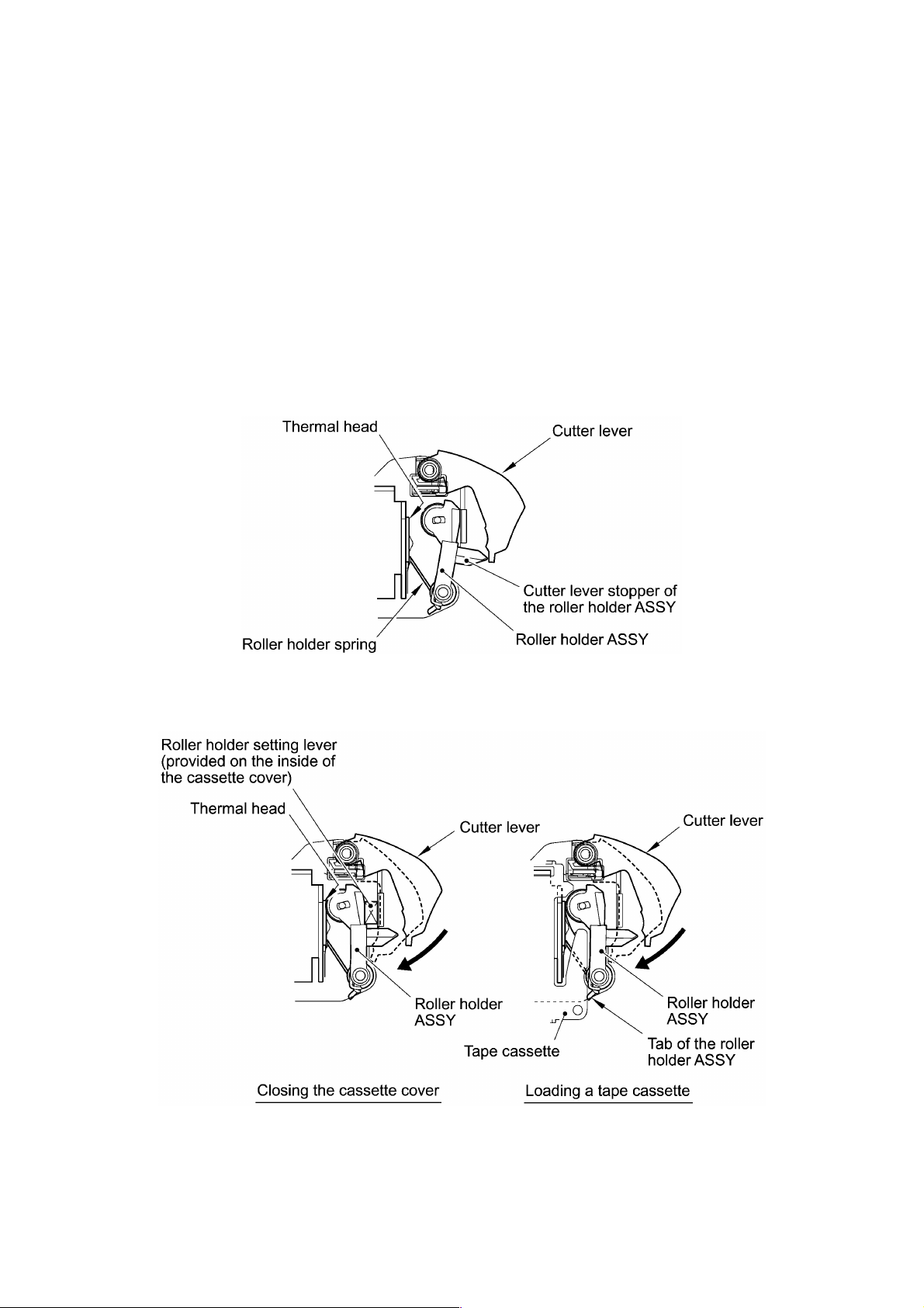
2.1.5 Cutter Safety Lock Mechanism
When the cassette cover is opened and no tape cassette is loaded, the roller holder ASSY
is retracted from the thermal head with the roller holder spring (as described in Subsection
2.1.2). In this retracted position, the cutter lever stopper of the roller holder ASSY blocks
the end of the cutter lever, preventing the cutter lever from pushing the cutter blade out of
the cutter unit for safety, as shown below.
Closing the cassette cover or loading a tape cassette releases the cutter safety lock
mechanism. If you close the cassette cover, the roller holder ASSY pivots towards the
thermal head so that the cutter lever stopper does not interfere with the cutter lever.
When a tape cassette is loaded, its outer edge pushes the tab of the roller holder ASSY to
pivot the roller holder ASSY towards the thermal head so that the cutter lever stopper
does not interfere with the cutter lever.
Figure 2.1-5 Cutter Safety Lock Mechanism
Figure 2.1-6 Releasing the Cutter Safety Lock Mechanism
II - 5
Page 19

2.2 DISASSEMBLY & REASSEMBLY
Safety Precautions
(1) You should carry out disassembly & reassembly jobs on an anti-static sheet
grounded correctly. Otherwise, the LSI and other electronic devices will be damaged
due to the electricity charged in your body.
(2) When transporting PCBs, be sure to wrap them in conductive sheets such as
aluminum foil.
(3) When using soldering irons and other heat-generating tools, take care not to damage
the resin parts such as wires, PCBs, and covers.
(4) Be careful not to lose screws, washers, or other parts removed for parts replacement.
(5) Tighten screws to the torque values listed below.
Tightening Torque List
Location Screw type Q'ty Tightening torque
Bottom cover Taptite, bind B M2.6 x 6 2 0.39 N•m (4 kgf•cm)
Chassis ASSY Taptite, bind B M2.6 x 4 3 0.196 N•m (2 kgf•cm)
Chassis ASSY (for DC motor) Screw, pan M1.7 x 2.5 2 0.10 to 0.196 N•m (1 to 2 kgf•cm)
Thermal head ASSY Screw, cup M2.6 x 4 1 0.49 N•m (5 kgf•cm)
Main PCB Taptite, bind B M2.6 x 4 2 0.196 N•m (2 kgf•cm )
Lens Taptite, bind B M2.6 x 4 2 0.196 N•m (2 kgf•cm )
Select dial Taptite, bind B M2.6 x 4 3 0.196 N•m (2 kgf•cm )
II - 6
Page 20
2.2.1 Disassembly Procedure
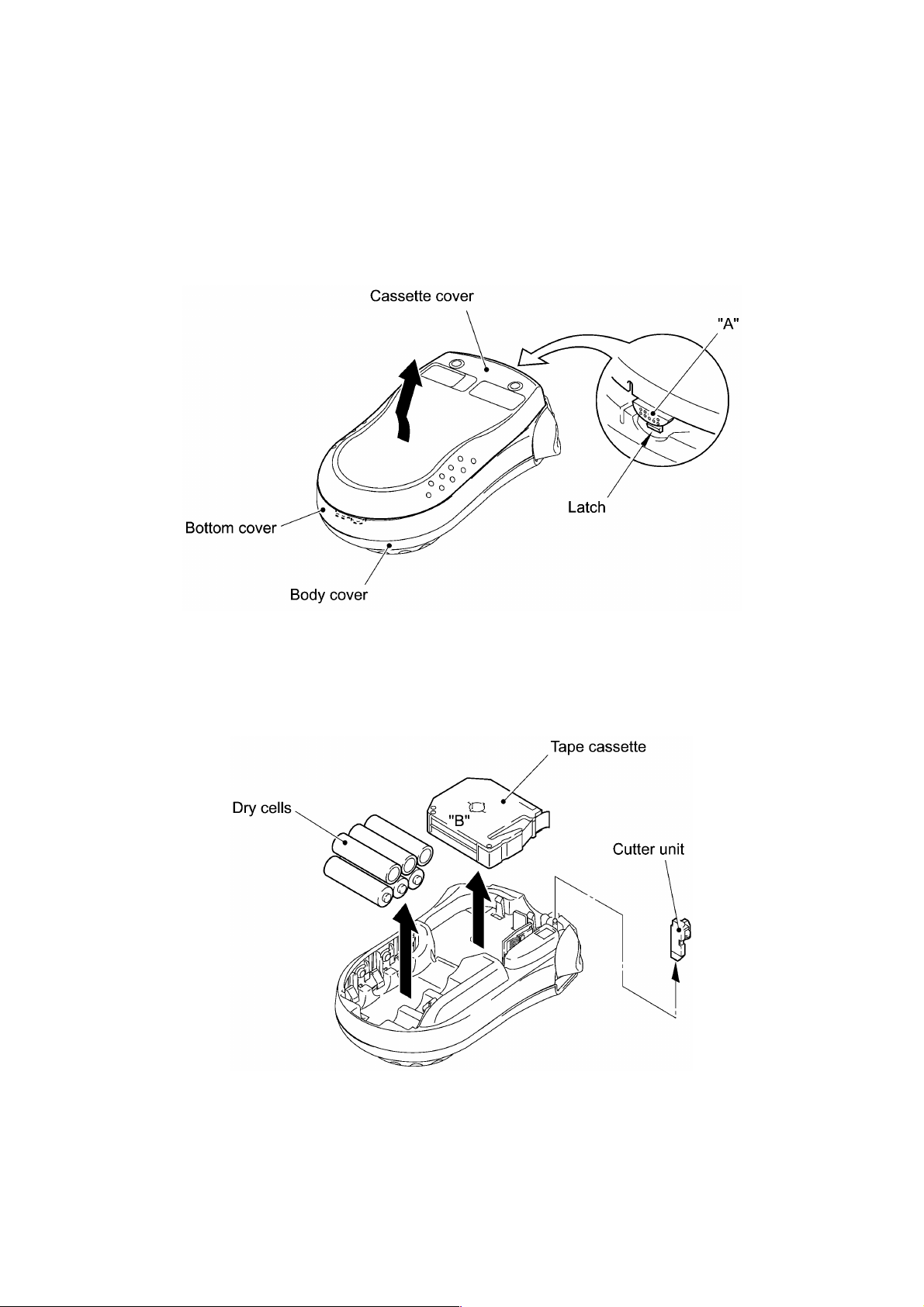
[ 1 ] Removing the Cassette Cover, Dry Cells, Tape Cassette, and Cutter Unit
(1) Turn the machine upside down.
(2) Press section "A" of the cassette cover to release the latch, and then remove the
cassette cover.
Figure 2.2-1 Removing the Cassette Cover
(3) Remove six dry cells, tape cassette, and cutter unit. For easier removal of the tape
cassette, first lift up edge "B" and then pull it out.
Figure 2.2-2 Removing the Dry Cells, Tape Cassette, and Cutter Unit
II - 7
Page 21

[ 2 ] Removing the Chassis ASSY
(1) Remove the two screws from the bottom cover.
Figure 2.2-3 Unscrewing the Bottom Cover
(2) Slightly open the bottom cover, discharge capacitor C5 with a screwdriver or the like,
and then disconnect the head flat cable from the main PCB, as illustrated below.
NOTE: Take care not to bend the head flat cable.
Figure 2.2-4 Discharging Capacitor C5 and Disconnecting the Head Flat Cable
II - 8
Page 22

(3) Unsolder the motor lead wires from the main PCB.
NOTE: Do not unsolder the wires of the plus and minus terminal ASSYs.
(4) Remove the three screws from the chassis ASSY.
Figure 2.2-5 Unsoldering the Motor Lead Wires and Removing the Chassis ASSY
(5) Lift the chassis ASSY up and out of the bottom cover. The cutter lever also comes
off.
II - 9
Page 23

Disassembling the Chassis ASSY
When handling the thermal head ASSY, do not touch the thermal head by hand. It may be
easily damaged due to the electricity charged in your body.
(1) Remove the screw from the thermal head ASSY and take off the ASSY.
(2) Remove the retaining ring from the shaft of the chassis ASSY.
(3) Pull up the roller holder ASSY together with its spring.
(4) Remove the two screws from the chassis ASSY and take off the DC motor ASSY.
Figure 2.2-6 Disassembling the Chassis ASSY
II - 10
Page 24

[ 3 ] Removing the Main PCB
(1) From the battery holder side of the bottom cover, unlatch the locking pawl of each of
the plus and minus terminal ASSYs with the tip of a flat screwdriver, and then push
them out of the bottom cover.
Figure 2.2-7 Pushing out the Plus and Minus Terminal ASSYs from the Bottom Cover
II - 11
Page 25

(2) Remove two screws from the main PCB.
(3) While pressing the guides of the LCD flat cable outwards, slightly slide the LCD flat
cable to the right and left and release it.
NOTE: Take care not to bend the LCD flat cable.
(4) Unlatch the LCD and take it out gently.
Figure 2.2-8 Taking out the Main PCB (with the LCD) from the Body Cover
II - 12
Page 26

[ 4 ] Removing Battery Terminals P1 and P2
(1) As shown below, remove battery terminals P1 from the bottom cover with the flat
screwdriver.
Figure 2.2-9 Taking out Battery Terminals P1 from the Bottom Cover
(2) As shown below, remove battery terminals P2 with the flat screwdriver.
Figure 2.2-10 Taking out Battery Terminals P2 from the Bottom Cover
II - 13
Page 27

[ 5 ] Removing the Rubber 4 Key, Lens, Dial Sheet, Select Dial, Select Dial Claw, and
Enter Key
(1) Remove the rubber 4 key.
(2) Remove the two screws from the lens and take it out.
Figure 2.2-11 Removing the Rubber 4 Key and Lens
(3) Remove the three screws and take out the dial sheet. The select dial also comes off.
(4) Remove the select dial claw from the body cover.
(5) Unlatch the Enter key from the select dial.
Figure 2.2-12 Removing the Dial Sheet, Select Dial, Select Dial Claw, and Enter key
II - 14
Page 28

2.2.2 Reassembly Procedure
[ 1 ] Installing the Enter Key, Select Dial Claw, Select Dial, Dial Sheet, Lens, and Rubber
4 Key
(1) Apply a rice-sized pinch of grease (Shin-Etsu Silicone G501) to each of the two
lubrication points on the end of the body cover which the inside of the select dial will
come into contact with, as shown below.
(2) Snap the Enter key into the select dial according to the orientation keys.
(3) Set the select dial claw to the body cover.
After setting, apply a rice-sized pinch of grease (Shin-Etsu Silicone G501) to the top
of the select dial claw, as shown below.
(4) Place the body cover upside down.
(5) Set the select dial to the body cover while aligning any low section of the inner dial
face with the top of the select dial claw.
(6) While pushing up the select dial, put the dial sheet. Secure the select dial and dial
sheet with three screws.
(7) Check that the select dial rotates smoothly.
Figure 2.2-13 Reinstalling the Enter Key, Select Dial Claw, Select Dial, and Dial Sheet
II - 15
Page 29

(8) Secure the lens with two screws.
(9) Set the rubber 4 key into place.
Figure 2.2-14 Reinstalling the Rubber 4 key and Lens
II - 16
Page 30

[ 2 ] Installing Battery Terminals P2 and P1
(1) Snap battery terminals P2 into the bottom cover.
Figure 2.2-15 Setting Battery Terminals P2
(2) Snap battery terminals P1 into the bottom cover.
Figure 2.2-16 Setting Battery Terminals P1
II - 17
Page 31

[ 3 ] Installing the Main PCB
(1) Secure the main PCB to the body cover with two screws.
(2) Route the LCD flat cable through the cable guides while pressing them outwards.
(3) Set the LCD into place while pressing the arms outwards.
Figure 2.2-17 Reinstalling the Main PCB
(4) Snap each of the plus and minus terminal ASSYs into the bottom cover.
Figure 2.2-18 Setting the Plus and Minus Terminal ASSYs
II - 18
Page 32

[ 4 ] Installing the Chassis ASSY
(1) If the chassis ASSY has been disassembled, assemble the components, referring to
page II-21.
(2) As shown in Figure 2.2-22, fit the cutter lever onto the shaft on the chassis ASSY.
(3) Put the chassis ASSY together with the cutter lever back into the bottom cover.
NOTE: Route the head flat cable as illustrated below.
(4) Secure the chassis ASSY with three screws.
(5) Solder the motor lead wires to the main PCB as shown below.
NOTE: Check the wire ID colors, then solder the black and red wires to the BLACK
(−) and RED (+) points, respectively.
Figure 2.2-19 Installing the Chassis ASSY and Soldering the Motor Lead Wires
II - 19
Page 33

(6) While holding the bottom cover in an angle shown below, connect the head flat cable
to the main PCB.
(7) Close the bottom cover.
Figure 2.2-20 Connecting the Head Flat Cable
(8) Secure the bottom cover to the body cover with two screws, taking care not to pinch
the wires between those covers.
Figure 2.2-21 Securing the Bottom Cover to the Body Cover
II - 20
Page 34

Assembling the Components of the Chassis ASSY
(1) Secure the DC motor ASSY to the chassis with two screws so that the motor lead
wires face as shown below.
(2) Set the roller holder spring onto the roller holder ASSY so that its straight end is fitted
into section "A" on the ASSY, then install them to the chassis and secure the ASSY
with the retaining ring.
(3) As shown below, turn the bent end of the roller holder spring with a flat screwdriver
and fit it into an oval hole provided in the chassis. Then secure the thermal head
ASSY with a screw.
Figure 2.2-22 Assembling the Components of the Chassis ASSY
II - 21
Page 35

[ 5 ] Setting the Cutter Unit, Tape Cassette, Dry Cells, and Cassette Cover
(1) Set the cutter unit into place.
(2) Set a tape cassette.
(3) Load six dry cells.
(4) First fit the hook of the cassette cover and then snap the cover into place.
Figure 2.2-23 Setting the Cutter Unit, Tape Cassette, Dry Cells, and Cassette Cover
II - 22
Page 36

[ 6 ] Final Operation Check
After reassembling, do the following:
(1) Load dry cells. The display should blink.
(2) Press the Power key twice. The calendar clock should appear.
(3) Turn the select dial to the desired position and press the Enter key. The selected
symbol should be established.
(4) Press the Print key. The selected item should be printed out.
(5) Push the cutter lever. The cutter lever should work smoothly and cut off the tape.
(6) Check that the printout is not faint.
(7) Open the cassette cover and remove the tape cassette and dry cells.
The above final operation check should be usually made. For your reference, the
inspection mode is described in [ 7 ].
II - 23
Page 37

[ 7 ] Inspection Mode
Enter the inspection mode according to the procedure given below and make the final
check.
In the inspection mode, you use four submodes--INFO, DIAL, CUT, and PRINT1
submodes.
TIP: The inspection mode supports a total of nine submodes for factory checking. That is,
there are five more submodes which are not described in this manual. Even if the machine
enters any of those five modes, you do not need to perform them. To escape from the
mode and proceed to any of the INFO, DIAL, CUT, and PRINT1 submodes, rotate the
select dial to any of Dial positions 1 to 4, respectively, and then press the Enter key.
(1) Check that the LCD shows the calendar clock or its setting screen.
(2) Set the select dial to Blank position.
(3) While holding down the Print key, press the Function key ("f").
The machine enters the inspection mode and shows the following on the LCD:
NOTE: If the following message appears and the machine automatically turns itself
off, then check the solder points on the main PCB. Two or more solder points may be
closed or wrong solder point may be closed.
II - 24
Page 38

INFO submode (Dial position 1 and Enter key*)
(*In any other submode, setting the select dial to Dial position 1 and pressing the Enter key
will jump to INFO submode, except during checking in DIAL submode.)
The moment the machine enters the inspection mode, it shows "INFO," indicating
that the machine is placed in INFO submode.
In INFO submode, you may check the destination, head rank, voltage level, calendar
clock, and LCD operation.
1) Press the Enter key.
The following screen (sample) will appear where you may check the destination,
head rank, voltage level, and calendar clock.
Head rank Voltage level
Destination Calendar clock
Destination
If the destination is USA or Canada, for example, "US" will display.
(The destination is determined by solder points 1 through 5.)
Destination
USA/Canada US H H H H H
France FR L H H H H
Germany GE H L H H H
Switzerland SZ H H L H H
Belgium BE H H H L H
Netherlands
(Holland)
England UK H H H H H
Ireland UK H H H H H
South Africa UK H H H H H
Italy IT L H H H H
Spain SP H L H H H
Denmark DE L H H H H
Norway NO H L H H H
Sweden SW H H L H H
The LCD
shows:
HOHHHHL
12345
H (High): Solder point opened L (Low): Solder point closed
Solder points
Head rank
Generally " " will display.
Solder points A through C are reserved for future use for thermal head ranking.
Unless otherwise specified, all of those solder points should be opened.
Voltage level
If the voltage level is within the specified range (9.0 ±0.2V), "0" will display. If not,
"X" will display.
Calendar clock
In the rightmost column of the LCD ("X" in the illustration above), the clock cycles
through 1, 2, 3, 4, and 5.
II - 25
Page 39

2) Press the Enter key.
LCD check screen 1 will appear as shown below.
3) Press the Enter key.
LCD check screen 2 will appear as shown below.
(All guidance indicators & cursors: ON)
4) Press the Enter key.
LCD check screen 3 will appear as shown below.
(All guidance indicators & cursors: ON)
DIAL submode (Dial position 2 and Enter key*)
(*In any other submode, setting the select dial to Dial position 2 and pressing the Enter key
will jump to DIAL submode.)
1) When LCD check screen 3 is displayed, press the Enter key.
The machine shows the following and enters DIAL submode.
2) Make sure that the select dial is placed in Dial position 0 (Blank). If it is in any
other position, turn the select dial to Dial position 0.
3) Press the Enter key.
"0" will display as shown below.
II - 26
Page 40

4) Counterclockwise turn the select dial slowly and check that the correct dial
position number will be displayed.
NOTE: Do not turn the select dial quickly or clockwise. Doing so cannot check the
dial operation correctly. If the select dial is set to any wrong position, "X" will
display as shown below. In the sample below, the select dial should be set to Dial
position 2 but now it is set to any other position. Turn the select dial to Dial
position 2 clockwise or counterclockwise.
5) After checking dial position 31, turn the select dial to the next position (Dial
position 0), then "OK" will appear and "OK" will be printed.
After printing is complete, the screen will automatically change from "OK" to
"CUT."
6) Press the cutter lever and cut the tape.
CUT submode (Dial position 3 and Enter key*)
(*In any other submode, setting the select dial to Dial position 3 and pressing the Enter key
will jump to CUT submode, except during checking in DIAL submode.)
The cutter operation may be checked in any other submode, so you may skip this
CUT submode and proceed to PRINT1 submode. To do so, turn the select dial to Dial
position 4 and press the Enter key.
1) Press the Enter key.
While displaying the following, the machine will feed tape.
II - 27
Page 41

After feeding tape, the machine will display the following:
2) Press the Enter key.
While displaying the following, the machine will feed tape.
After feeding tape, the machine will display the following:
3) Press the Enter key.
While displaying the following, the machine will feed tape.
After feeding tape, the machine will display the following:
PRINT1 submode (Dial position 4 and Enter key*)
(*In any other submode, setting the select dial to Dial position 4 and pressing the Enter key
will jump to PRINT1 submode, except during checking in DIAL submode.)
1) When "3" is displayed, press the Enter key.
The machine shows the following and enters PRINT1 submode.
2) Press the Enter key.
The machine will print out the following print sample (247 dots, 25.2 ±3 mm in
length):
After printing, the machine will automatically escape from the inspection mode
and return to the clock mode.
If the machine remains in PRINT1 submode, press the Enter key.
II - 28
Page 42

Chapter III.
ELECTRONICS
Page 43

CONTENTS
CHAPTER III. ELECTRONICS
3.1 OUTLINE OF CONTROL ELECTRONICS.......................................................................... III-1
3.1.1 Configuration.......................................................................................................... III-1
3.2 MAIN PCB .......................................................................................................................... III-2
3.2.1 Block Diagram........................................................................................................ III-2
3.2.2 CPU .......................................................................................................................III-3
3.2.3 LCD Driver ............................................................................................................. III-3
3.2.4 Key Contacts and Solder Points............................................................................. III-4
3.2.5 ON/OFF Key and Its Circuit.................................................................................... III-6
3.2.6 Thermal Head Drive Circuit .................................................................................... III-8
3.2.7 Oscillation Circuit ................................................................................................... III-9
3.2.8 Voltage Detection Circuit........................................................................................ III-9
3.2.9 Power Supply Circuit............................................................................................ III-10
3.2.10 Motor Drive Circuit ...............................................................................................III-10
3.2.11 Dial Position Detection Circuit .............................................................................. III-12
Page 44

3.1 OUTLINE OF CONTROL ELECTRONICS
3.1.1 Configuration
Figure 3.1-1 shows a block diagram of the control electronics of this machine. The control
electronics consists of a main PCB, DC motor, and thermal print head ASSY.
Figure 3.1-1 Configuration of the Electronic Part
Main PCB
This manages all the components including an LCD, DC motor, keypad, and thermal print
head ASSY.
Motor
The DC motor is a power source to advance tape.
Thermal Print Head
This is a thick-film thermal print head which integrates a heat generator (consisting of 64
heating elements vertically aligned) and driver circuitry.
III - 1
Page 45

3.2 MAIN PCB
3.2.1 Block Diagram
Figure 3.2-1 shows a block diagram of the main PCB.
Figure 3.2-1 Block Diagram of Main PCB
The main PCB consists of the following:
(1) CPU (including a ROM and RAM)
(2) LCD driver
(3) Key contacts and solder points
(4) ON/OFF key and its circuit
(5) Thermal head drive circuit
(6) Oscillation circuit
(7) Voltage detection circuit
(8) Power supply circuit
(9) Motor drive circuit
(10) Dial position detection circuit
III - 2
Page 46

3.2.2 CPU
The CPU (U1: MN101C30A) is an 8-bit microprocessor produced by CMOS silicon gate
process. which integrates a 32-kilobyte ROM and a 1.5-kilobyte RAM.
It controls and manages the entire system.
3.2.3 LCD Driver
Figure 3.2-2 shows a LCD driver.
Figure 3.2-2 LCD Driver
The LCD driver (U3: SPLC780A) is an LSI which has common drive pins and column
drive pins to drive the LCD.
R16 is an oscillation register that issues display timing signals.
V1 to V5 of the LCD driver divide Vcc by RA3·R15 to produce multi-level power sources
required for driving the LCD. To display data, the CPU writes data onto RS, RW, E, and
DB4 through DB7 of the LCD driver.
III - 3
Page 47

3.2.4 Key Contacts and Solder Points
On the main PCB are four carbon-printed contact patterns. Each contact pattern has a
pair of electrodes.
Keypad
The rubber keypad is made of high-impedance silicon rubber. As shown in Figure 3.2-3,
each key on the rubber keypad consists of a key top, rubber spring, and conductive paint
which functions as a switching element.
If a particular key is pressed, the conductive paint of the key short-circuits the paired
electrodes carbon-printed on the main PCB.
Figure 3.2-3 Detailed Diagram of Keypad
Key scanning
Figure 3.2-4 shows the key scan circuit and solder points.
The CPU scans four keys including the ON/OFF key. Ports P50 through P53 on the CPU
issue a group of key scanning pulses. Port P20 acts as an input port that receives key
status.
Ports P70 through P77 act as input ports that receive solder point status.
Figure 3.2-4 Key Scan Circuit and Solder Points
III - 4
Page 48

Scanning timing
The CPU turns ports P50, P51, P52, and P53 Low in this order. When not Low, those
ports are High or in high impedance. When a particular port out of them is Low, the CPU
reads the status of port P20.
The CPU scans those key contacts every 10 ms. If the CPU reads the ON state on an
input port two successive times, then it interprets it as the key being pressed; if the CPU
reads the OFF state six successive times, it interprets it as the key being released.
The input mode of this keying system is 2-key roll-over and 3-key lockout.
Figure 3.2-5 Key Scan Timing Scheme and Scanning Pulse Outputs
Solder points
The CPU reads the solder point status once in the powering-in sequence to recognize the
customization.
Solder points 1 through 5 customize the machine for the destination (shipping country).
06 Netherlands (Holland) H H H H L 08 Spain H L H
05
Belgium
04 Switzerland H H L
03 France L H H
01 Germany H L H
Spec
No.
10 U.S.A./Canada H H H
Spec
No.
H: Solder point opened L: Solder point closed
Destination
Destination
H
H H
1 2 3
Solder Points
1 2 3
Solder Points
L H
H H
H H
H H
4 5
H H
4 5
07 Italy L H H
02 England/Ireland H H H
Spec
No.
12 Sweden H H L
11 Norway
09 Denmark L H H
Spec
No.
Destination
Destination
1 2 3
Solder Points
L H
H
1 2 3
Solder Points
H H
H H
H H
4 5
H H
H
H H
4 5
H
Solder points A through C are reserved for the future use for the thermal head ranking.
According to the soldered status, the CPU determines the ON-time length of the thermal
print head.
III - 5
Page 49

3.2.5 ON/OFF Key and Its Circuit
ON/OFF key
As shown in Figure 3.2-6, pressing the ON/OFF key turns the CPU's IRQ0 Low so as to
interrupt the CPU.
Releasing the ON/OFF key turns the IRQ0 High. Upon detection of the High IRQ0, the
CPU checks the P11 and P13 status. According to the status, it switches to the normal
operation mode, calendar clock mode, or LCD OFF mode.
Figure 3.2-6 ON/OFF Sequence
Switching between calendar clock mode and LCD OFF mode
Port P11 on the CPU switches Vcc that is connected to the photo-interrupter and thermal
print head. Port 13 switches LVcc that is connected to the LCD driver and its divider
resistor.
If the CPU sets P11 in high impedance to turn Vcc to 0V, then pressing the ON/OFF key
switches to the calendar clock mode.
If the CPU sets P13 to 0V to turn LVcc to 0V, then pressing the ON/OFF key switches to
the LCD OFF mode.
Figure 3.2-7 Mode Switching Circuit
III - 6
Page 50

Automatic powering-off
If you make no key entry for approx. 1 minute, the CPU automatically enters calendar
clock mode or LCD OFF mode when Vcc is 0V (P11 is in high impedance) or LVcc is 0V
(P13 at 0V), respectively.
Pressing the ON/OFF key in calendar clock mode or LCD OFF mode switches to normal
operation mode.
III - 7
Page 51

3.2.6 Thermal Head Drive Circuit
Figure 3.2-8 shows the thermal head drive circuit.
The thermal head has an integrated heat generator (consisting of 64 heating elements
vertically aligned in 180 dpi) and a built-in driver IC.
Synchronizing with the clock on SBT0, the CPU outputs print data on SBO0 in serial form.
One issue contains a total of 64 dots, 8 sets of 8-bit data.
Figure 3.2-8 Thermal Head Drive Circuit
Figure 3.2-9 shows a timing chart for thermal head drive.
Figure 3.2-9 Timing Chart for Thermal Head Drive
Upon receipt of LATCH signal issued through P01, the thermal head drive circuit latches
the serial data sent through SBO0 and supplies the power to the thermal head ASSY
according to the STROBE signal issued through P03.
The CPU controls the ON-time length of the thermal print head according to the V
applied to the thermal head. If the V
BT level is low, the CPU increases the ON-time length;
BT level
if high, the CPU decreases it.
III - 8
Page 52

3.2.7 Oscillation Circuit
Figure 3.2-10 shows the oscillation circuit.
This circuit contains two oscillators to generate 8.00 MHz frequency which acts as a CPU
basic clock and 32.768 kHz frequency for calendar clock.
Figure 3.2-10 Oscillation Circuit
3.2.8 Voltage Detection Circuit
Figure 3.2-11 shows the voltage detection circuit.
Figure 3.2-11 Voltage Detection Circuit
This circuit, which is composed of divider resistors R8 and R9, steps down the power
source V
BT fed from dry cells and feeds the output to analog input port AN1 on the CPU.
According to the drive source voltage, the CPU determines the optimum head driver
power.
If the voltage drops below the following level:
in entry mode or
during printing
approx. 5.86V approx. 5.35V Display the "BATTERY" message.
approx. 5.35V approx. 4.94V
approx. 2.90V
in clock mode
Turn the LCD off. (The internal clock
remains on.)
Turn itself off. (The internal clock and other
settings will be reset.)
III - 9
Then, the machine will:
Page 53

3.2.9 Power Supply Circuit
Figure 3.2-12 shows a power supply circuit.
The 3-terminal regulator (RH5RL33A) stabilizes the battery output, producing the 3.3V
power source. Capacitor C13 is for the logic circuit and C5 is for driving the thermal head
and DC motor.
3.2.10 Motor Drive Circuit
Figure 3.2-13 shows the drive circuit of the DC motor which feeds tape.
Through P10, the CPU produces a start/stop control signal to the motor drive circuit.
Figure 3.2-14 shows waveforms of control signal and motor drive current.
Figure 3.2-12 Power Supply Circuit
Electronic governor IC (U4: BA6220) controls this circuit to keep the rotation speed of the
DC motor constant even if the power supply voltage (V
BT) varies.
Figure 3.2-13 Motor Drive Circuit
III - 10
Page 54

Figure 3.2-14 Waveforms of Control Signal and Motor Drive Current
III - 11
Page 55

3.2.11 Dial Position Detection Circuit
Dial LED scanning
Figure 3.2-15 shows the LED scan circuit that detects the dial position.
The CPU scans five LEDs. Ports LED0 through LED4 on the CPU issue a group of LED
scanning pulses. Port AN2 through AN6 act as input ports that receive LED status.
Scanning timing
The CPU turns ports LED0, LED1, LED2, LED3, and LED4 Low in this order. When not
Low, those ports are High or in high impedance. When a particular port out of them is
Low, the CPU reads the status of the corresponding port.
The CPU scans those LEDs every 50 ms. If the CPU reads the same pattern on input
ports five successive times, then it interprets it as the current dial position.
Figure 3.2-16 shows the waveforms of dial LED scanning pulse outputs.
Figure 3.2-15 Dial Position Detection Circuit
III - 12
Page 56

Figure 3.2-16 Waveforms of Dial Scanning Pulse Outputs
III - 13
Page 57

Chapter IV.
TROUBLESHOOTING
Page 58

CONTENTS
CHAPTER IV. TROUBLESHOOTING
4.1 TROUBLESHOOTING........................................................................................................ IV-1
4.1.1 Precautions ............................................................................................................IV-1
4.1.2 After Repairing.......................................................................................................IV-1
4.1.3 Troubleshooting Flows ...........................................................................................IV-2
[ 1 ] Tape feeding failure ............................................................................................... IV-2
[ 2 ] Printing failure........................................................................................................ IV-3
[ 3 ] Powering failure (Nothing appears on the LCD.) ....................................................IV-4
[ 4 ] Abnormal LCD indication........................................................................................IV-5
[ 5 ] No key entry possible............................................................................................. IV-5
Page 59

4.1 TROUBLESHOOTING
This section gives the service personnel some of the troubleshooting procedures to be
followed if an error or malfunction occurs with this machine. It is impossible to anticipate
all of the possible troubles which may occur in future and determine the troubleshooting
procedures, so this chapter covers some sample troubles. However, those samples will
help service personnel pinpoint and repair other defective elements if he/she analyzes
and examines them well.
4.1.1 Precautions
Be sure to observe the following precautions to prevent the secondary problems from
happening during troubleshooting:
(1) Get a good idea of what the trouble is. Whenever more than one trouble source is
found, plan the most reasonable repairing procedure after reviewing the relationship
between them.
(2) When supplying power to this machine having problems, make sure that its output
voltage level is 8 to 10V under no load.
(3) When starting disassembly jobs, first remove dry cells and discharge electrolytic
capacitor C5.
(4) To repair an error which occurred in the thermal print head and its related sections,
disconnect the thermal head cable until repairs are finished.
4.1.2 After Repairing
After repairing the defective section, be sure to check again to see if the repaired section
works correctly. In particular, if you replace the main PCB, make a final operation check
given in CHAPTER II, Subsection 2.2.2, [ 6 ].
Make a note of the troubleshooting procedure so that it will be handy should problems
occur in the future.
IV - 1
Page 60

4.1.3 Troubleshooting Flows
[ 1 ] Tape feeding failure
IV - 2
Page 61

[ 2 ] Printing failure
IV - 3
Page 62

[ 3 ] Powering failure (Nothing appears on the LCD.)
IV - 4
Page 63

[ 4 ] Abnormal LCD indication
[ 5 ] No key entry possible
IV - 5
Page 64

APPENDIX
Circuit Diagram
Main PCB
Page 65

Appendix. Main PCB
D2 short-circuit pattern
P22, RA2 short-circuit
R2 short-circuit pattern
DA1 short-circuit pattern
C8 normal pattern
R10 short-circuit pattern
NAME
CIRCUIT DIAGRAM BB4
Electronic devices enclosed by a dotted line are not mounted.
CODE
LA6235000
Page 66

Aug., 2001
8V2018BE0
Printed in Japan
 Loading...