

Brother MX-2002, MX-2003, MX-2001 Service Manual

R
MAILBOX UNIT
FOR LASER PRINTER
SERVICE MANUAL
MODEL:MX-2001 / MX-2002 / MX-2003
Note:
While the MX-2001 Mailbox unit is available in all countries, the MX-
2003 is available in U.S. and Canada only, and the MX-2002 is
available in the other countries than U.S. and Canada.
Oct., 1998
54T050NE0

© Copyright Brother 1998
All rights reserved.
No part of this publication may be reproduced in any form or by any means without permission in
writing from the publisher.
Specifications are subject to change without notice.
Trademarks:
The brother logo is a registered trademark of Brother Industries, Ltd.
Apple, the Apple Logo, and Macintosh are trademarks, registered in the United States and other
countries and True Type is a trademark of Apple computer, Inc.
Epson is a registered trademark and FX-80 and FX-850 are trademarks of Seiko Epson
Corporation.
Hewlett Packard is a registered trademark and HP Laser Jet is a trademark of Hewlett Packard
Company.
IBM, IBM PC and Proprinter are registered trademarks of International Business Machines
Corporation.
Microsoft and MS-DOS are registered trademarks of Microsoft Corporation.
Windows is a registered trademark of Microsoft Corporation in the U.S. and other countries.

PREFACE
This service manual contains basic information required for after-sales service of the optional
Mailbox unit, MX-2001/MX-2002/MX-2003 for the HL-2060 laser printer (hereinafter referred to as
“this unit” or "the Mailbox unit"). This information is vital to the service technician to maintain the
high performance of the unit.
This service manual covers the MX-2001 / MX-2002 / MX-2003 Mailbox units.
The manual consists of the following chapters:
CHAPTER I : GENERAL
General view, specifications, etc.
CHAPTER II : THEORY OF OPERATION
Basic operation of the electrical system and the mechanical system
CHAPTER III : DISASSEMBLY
Procedures for disassembling the mechanical system.
CHAPTER IV : TROUBLESHOOTING
Reference values and adjustments, troubleshooting malfunctions, etc.
APPENDICES :
Information in this manual is subject to change due to improvement or re-design of the product. All
relevant information in such cases will be supplied in service information bulletins (Technical
Information).
A thorough understanding of this unit, based on information in this service manual and service
information bulletins, is required for maintaining its performance and for improving the practical
ability to find the cause of problems.
PCB CIRCUIT DIAGRAMS, ETC.

CONTENTS
CHAPTER I GENERAL............................................................................I-1
1. INSTRUCTIONS..........................................................................................................I-1
2. OVERVIEW.................................................................................................................I-2
3. SPECIFICATIONS.......................................................................................................I-3
3.1 Functions...............................................................................................................................I-3
3.2 Electrical and Mechanical .....................................................................................................I-3
3.3 Paper.....................................................................................................................................I-4
CHAPTER II THEORY OF OPERATION.................................................II-1
1. ELECTRONICS.........................................................................................................II-1
1.1 General Block Diagram...................................................................................................II-1
1.2 Main PCB........................................................................................................................II-3
1.2.1 CPU...............................................................................................................................II-3
1.2.2 Bin solenoid drive circuit................................................................................................II-3
1.2.3 Entrance solenoid drive circuit ......................................................................................II-3
1.2.4 Bin capacity sensor.......................................................................................................II-4
1.2.5 Infrared LED drive circuit...............................................................................................II-4
1.2.6 Power supply LED drive circuit......................................................................................II-4
1.3 I/F PCB ...........................................................................................................................II-4
1.3.1 Regulator.......................................................................................................................II-4
1.3.2 Serial I/F circuit..............................................................................................................II-5
1.3.3 Feeding motor drive circuit............................................................................................ II- 5
1.3.4 Entrance sensor input ................................................................................................... II-5
1.4 Sensor PCB....................................................................................................................II-5
1.5 Power supply LED PCB..................................................................................................II-5
1.6 Communication with the Printer......................................................................................II-5
2. MECHANICS.............................................................................................................II-7
2.1 General Overview of Mechanism....................................................................................II-7
2.2 Paper Feed Sequence....................................................................................................II-8
CHAPTER III DISASSEMBLY AND REASSEMBLY...............................III-1
1. SAFETY PRECAUTIONS.........................................................................................III-1
2. DISASSEMBLY FLOW.............................................................................................III-2
3. DISASSEMBLY PROCEDURE ................................................................................III-3
3.1 External Covers.............................................................................................................III-3
3.1.1 Cover UR (For MX-2001/2003 only)............................................................................. III-3
3.1.2 Cover UL (For MX-2001/2003 only) ............................................................................. III-3
3.1.3 Cover R........................................................................................................................III-4
3.1.4 Cover L.........................................................................................................................III-4
3.1.5 Rear Cover U ASSY (For MX-2001/2003 only)............................................................ III-5
3.1.6 Rear Cover A ASSY.....................................................................................................III-7
i

3.1.7 PCB Cover A (MX-2001) / PCB Cover B (MX-2002) / PCB Cover D (MX-2003 Upper
Unit)..............................................................................................................................III-8
3.1.8 Bin................................................................................................................................III-8
3.2 Remove the Main Frame Unit from the Under Frame Unit (For MX-2001/2003 only).III-10
3.3 Main Frame Unit ..........................................................................................................III-10
3.3.1 I/F PCB A ASSY (MX-2001) / I/F PCB B ASSY (MX-2002) / I/F PCB C ASSY (MX-2003
Lower Unit) / I/F PCB D ASSY (MX-2003 Upper Unit) ............................................... III-10
3.3.2 Feeding Motor ASSY.................................................................................................. III-11
3.3.3 Main PCB A ASSY (MX-2001, MX-2003 Lower Unit) / Main PCB B ASSY (MX-2002,
MX-2003 Upper Unit)..................................................................................................III-12
3.3.4 Solenoid A/B & LED PCB ASSY (MX-2001/2003 only)..............................................III-13
3.3.5 Sensor PCB ASSY.....................................................................................................III-14
3.3.6 Actuator A/B...............................................................................................................III-15
3.3.7 Eject Roller ASSY / Feed Rollers A/B ASSY..............................................................III-17
3.3.8 Eject Pinch Roller ASSY & Discharging Brush........................................................... III-19
3.4 Under Frame Unit (For MX-2001/2003 only)...............................................................III-20
3.4.1 Actuator U ..................................................................................................................III-20
3.4.2 Solenoid U..................................................................................................................III-21
3.4.3 Photo Interrupter ........................................................................................................III-21
3.4.4 Feed Roller U ASSY................................................................................................... III-22
3.4.5 Flap U.........................................................................................................................III-23
3.5 Remove the Upper Unit from the Lower Unit (For MX-2003 only)...............................III-24
3.6 Packing of MX-2003.....................................................................................................III-28
4. APPLICATION OF GREASE..................................................................................III-29
4.1 Rollers..........................................................................................................................III-29
4.1.1 Feed Roller A/B ASSY................................................................................................III-29
4.1.2 Eject Roller ASSY ......................................................................................................III -29
4.1.3 Feed Roller U ASSY................................................................................................... III-30
4.1.4 Pressure Roller / Pressure Roller U...........................................................................III-30
4.2 Gears...........................................................................................................................III-31
4.2.1 Gears on the Main Frame R.......................................................................................III-31
4.2.2 Gears on the Main Frame L........................................................................................III-31
4.2.3 Gears on the Frame UR.............................................................................................III-32
4.3 Others..........................................................................................................................III-32
CHAPTER IV TROUBLESHOOTING...................................................... IV-1
1. INITIAL CHECK ......................................................................................................IV-1
2. MTBF / MTTR .........................................................................................................IV-2
3. TROUBLESHOOTING............................................................................................ IV-3
APPENDICES
1. MAIN PCB CIRCUIT DIAGRAM (1/2).......................................................................A-1
2. MAIN PCB CIRCUIT DIAGRAM (2/2).......................................................................A-2
3. I/F PCB CIRCUIT DIAGRAM....................................................................................A-3
INDEX
ii
CHAPTER I GENERAL
1. INSTRUCTIONS
The MX-2001/2002/2003 Mailbox units are optionally installed onto the HL-2060 printer.
The MX-2001 Lower Mailbox unit consists of five bins. The MX-2002 Upper Mailbox
unit is additionally installed onto the MX-2001, and also consists of five bins. The MX2003 Mailbox unit consists of ten bins.
Note: While the MX-2001 Mailbox unit is available in all countries, the MX-2003 is
available in U.S. and Canada only, and the MX-2002 is available in the other
countries than U.S. and Canada.
The unit works as a
for each function.
Function Description
Stacker
Sorter
Mailbox
When you install the unit onto the printer, the printed paper is ejected to the output tray
of the printer and/or the bin(s) of the Mailbox unit by selection commands sent from the
printer.
stacker, sorter
Printed paper is ejected into the multiple bins behaving as a single
high-capacity tray.
Printed paper is ejected as a set for a print job into a bin when multiple
sets of documents are printed and collated.
Printed paper is ejected into the specific bin defined as your own mail
box.
and
mailbox
for the printer. See the table below
I-1
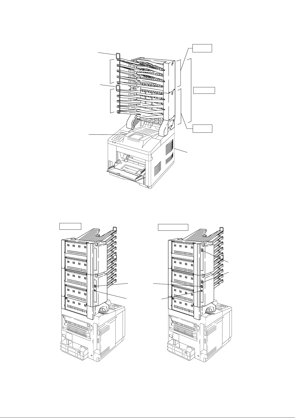
2. OVERVIEW
<Front View>
Printer Output
Paper Stopper
MX-2002
Bin 6 - 10
Paper Stopper
MX-2003
Bin 1 - 5
MX-2001
Tray
HL-2060 Printer
<Rear View>
MX-2003
Fig. 1.1
Modular jack
DC jack connector
MX-2001/2002
Mini DIN connector
Mini DIN connector
Fig. 1.2
I-2

3. SPECIFICATIONS
3.1 Function
(1) Stacking direction
Face down
(2) Feeding speed (when feeding A4 size paper)
Printer Mode When the paper is ejected into
multiple bins
20ppm mode 18 ppm 20 ppm
10ppm mode 9 ppm 10 ppm
(3) Bin capacity
Normal mode: 100 sheet/bin
Big stacker mode*: 300 sheet/bin
* When bins #2, #4, #7 and/or #9 are removed, bins #1, #3, #6 and/or #8 bin(s) as big
stacker bins with a capacity of 300 sheets each.
3.2 Electrical / Mechanical
(1) Power source
AC 100 to 240V, 50Hz/60Hz
When the paper is ejected
continuously into a single bin
(2) Power consumption
Printing: 25W or less (when MX-2001 is installed.)
45W or less (when both MX-2001 and MX-2002, or MX-2003 are
installed.)
Stand-by: 15W or less (when MX-2001 is installed.)
20W or less (when both MX-2001 and MX-2002, or MX-2003 are
installed.)
(3) Temperature
Operating: 10 to 32.5°C (50 to 90.5°F)
Storage: 0 to 40°C (38 to 104°F)
(4) Humidity
Operating: 20 to 80% (non condensing)
Storage: 10 to 85% (non condensing)
(5) Dimensions
MX-2001: 354 (W) x 356 (D) x 411 (H) mm
MX-2002: 354 (W) x 356 (D) x 337 (H) mm
MX-2003: 354 (W) x 356 (D) x 617 (H) mm
(6) Weight
MX-2001: Approx. 5.2 kg
MX-2002: Approx. 4.1 kg
MX-2003: Approx. 9.3 kg
I-3

3.3 Paper
(1) Paper type
Cut sheet
Normal paper / Specific recycled paper
*Special paper is not included.
(2) Feedable paper weight
60 ~ 90 g/m
2
(16 ~ 24lb.)
(3) Feedable paper thickness
0.075 ~ 0.12 mm
(4) Paper size
A4, Letter, Executive, ISO B5
(5) Recommended paper
Xerox 4200 (For U.S.) / RANK Xerox 80 g/m
2
Premier paper (For Europe)
I-4

CHAPTER II THEORY OF OPERATION
1. ELECTRONICS
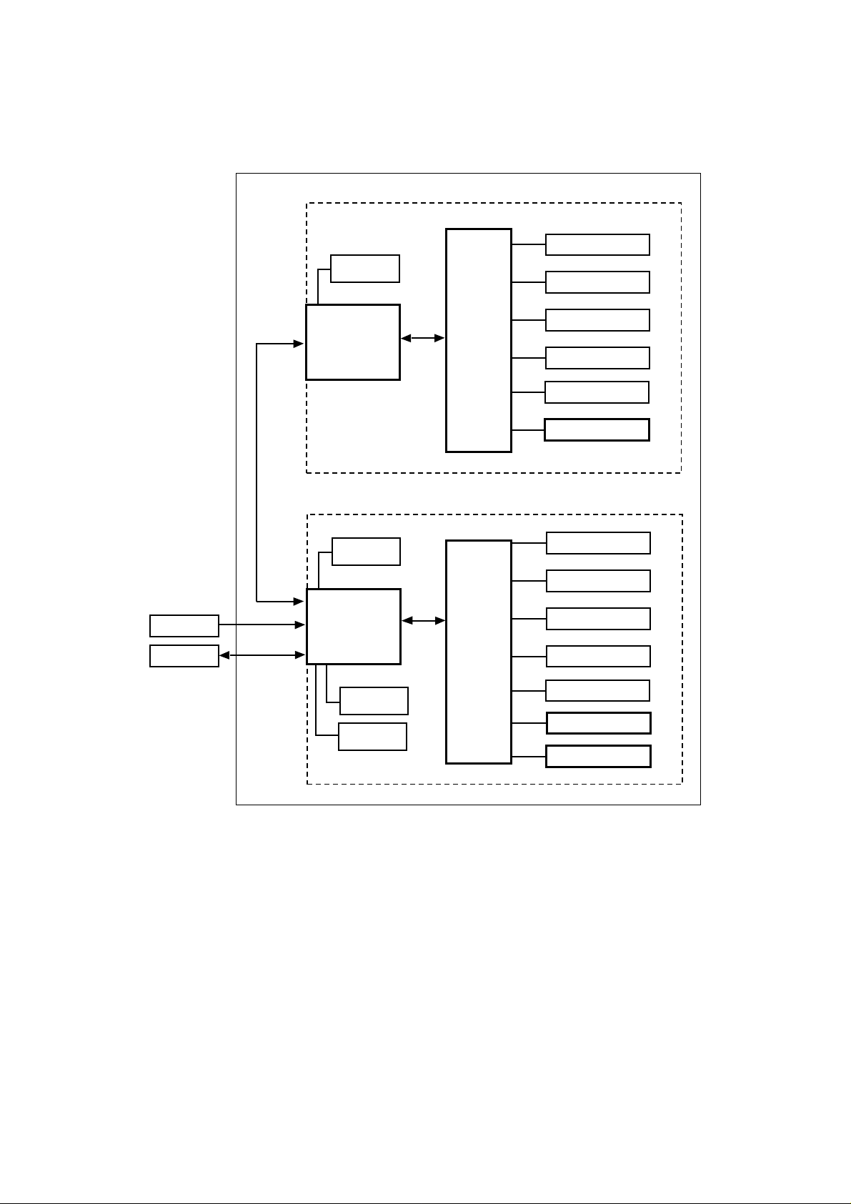
1.1 General Block Diagram
<MX-2001 & MX-2002>
The MX-2001 Mailbox unit is operated according to signals sent from the printer by serial
communication. The MX-2001 and MX-2002 also communicate with each other by serial
communication. Refer to Fig. 2.1 which shows the general block diagram of the MX-2001
and MX-2002.
<MX-2002>
Feeding
Motor
#10 bin solenoid
#9 bin solenoid
Adapter
Printer
Communication
Serial
+24V Input
Serial
Communication
I/F PCB
<MX-2001>
Feeding
Motor
I/F PCB
Entrance
Solenoid
Entrance
Sensor
Main PCB
Main PCB
#8 bin solenoid
#7 bin solenoid
#6 bin solenoid
Sensor PCB
#5 bin solenoid
#4 bin solenoid
#3 bin solenoid
#2 bin solenoid
#1 bin solenoid
Sensor PCB
LED PCB
Fig. 2.1
Note:
The following parts and circuits are not fitted on the PCBs in the MX-2002.
<Main PCB>
Entrance solenoid circuit
LED PCB circuit
<I/F PCB>
Entrance sensor circuit
DC jack connector for the adapter
Modular jack connection to the printer
II-1
<MX-2003>
The electronic system of the MX-2003 is basically the same with the one of MX2001/2002. Refer to Fig. 2.2 which shows the general block diagram of the MX-2003.
<MX-2003>
<Upper Unit>
#10 bin solenoid
Feeding
Serial
Communica-
tion
Motor
I/F PCB
Main PCB
#9 bin solenoid
#8 bin solenoid
#7 bin solenoid
#6 bin solenoid
Sensor PCB
Adapter
Printer
+24V Input
Serial
Communica-
tion
<Lower Unit>
Feeding
Motor
I/F PCB
Entrance
Solenoid
Entrance
Sensor
Fig. 2.2
Main PCB
#5 bin solenoid
#4 bin solenoid
#3 bin solenoid
#2 bin solenoid
#1 bin solenoid
Sensor PCB
LED PCB
II-2

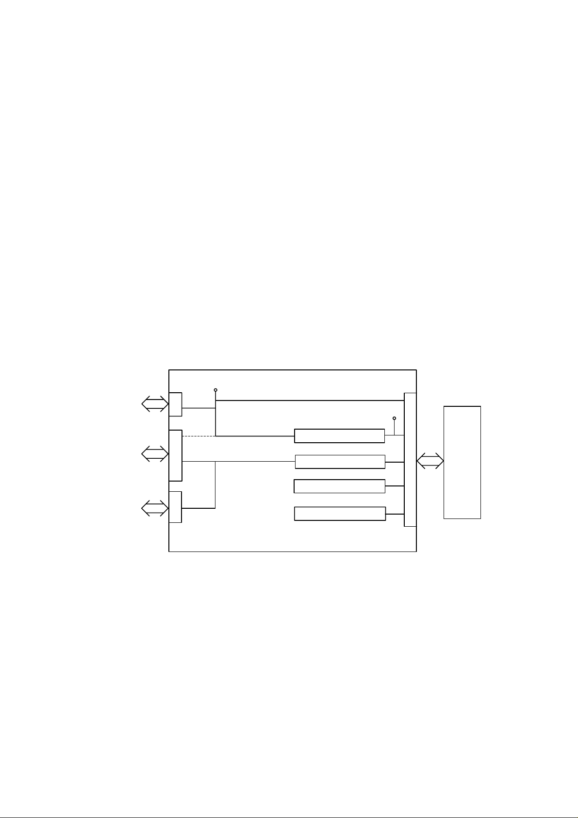
1.2 Main PCB
Fig. 2.2 shows the block diagram of the main PCB.
I/F PCB
+24V
+5V
Entrance solenoid drive circuit
GND
Main PCB
M50727
CPU
Bin solenoid drive circuit
(for each bin)
Bin capacity sensor
(for each bin)
Infrared LED drive circuit
Power supply LED drive circuit
Printer
Fig. 2.2
1.2.1 CPU
The CPU M50727 is a 4 bit one-chip microcomputer which controls the Mailbox unit and
communicates with the printer using serial communications. According to the commands
from the printer, the CPU drives the feeding motor and the solenoid of each bin and then
feeds the paper to the specified bin. If it detects paper full in the specified bin, the CPU
sends the signal to the printer.
1.2.2 Bin solenoid drive circuit
The bin solenoid drive circuit drives the solenoid of each bin which controls the diverter
flap to send the paper to each bin. The diverter flap is opened when the solenoid is
energized and the flap is closed when the solenoid is de-energized. Each drive circuit for
each of the five bins works independently.
This circuit provides a constant current drive to the solenoid. The solenoid is driven at
600mA for 200msec when it is first energized and then it is held by being driven at
150mA.
1.2.3 Entrance solenoid drive circuit
The entrance solenoid drive circuit drives the solenoid which controls the flap to switch
the paper eject tray from the printer to the Mailbox unit. It is the same as the bin solenoid
drive circuit and connected to the entrance solenoid through the I/F PCB.
II-3
1.2.4 Bin capacity sensor
The bin capacity sensors, which are five infrared LEDs, detect whether the bin is full or
not.
The infrared sensor output generated from the sensor PCB is shut off when the bin is full
of paper. The CPU recognizes that the bin is full when the infrared sensor output is shut
off for 20 seconds.
These sensors also detect paper jams. When paper is ejected into the bin, the sensor is
covered temporarily by the actuator. The CPU recognizes that a paper jam has occurred
when the sensor has not cleared after a specified time has passed.
1.2.5 Infrared LED drive circuit
The infrared LED drive circuit drives the five infrared LEDs on the sensor PCB. This
drive circuit is controlled by the CPU.
1.2.6 Power supply LED drive circuit
The power supply LED drive circuit drives the power supply LED when the regulated DC
power, +24V, is supplied when the adapter is connected and plugged in.
1.3 I/F PCB
Fig. 2.3 shows the block diagram of the I/F PCB.
I/F PCB
+24V
Adapter
Printer
Mail Box Unit
+24V
+24V
Serial I/F drive circuit
Feeding motor drive circuit
Entrance sensor input
Fig. 2.3
+5V
Regulator
Main PCB
1.3.1 Regulator
The regulator generates and supplies the +5V logic power supply from the +24V supplied
by the adapter.
If the adapter is not connected, the regulator generates the +5V logic power supply from
the +24V supplied by the printer. In this case, the +24V supplied by the printer is not
connected with the +24V supply that should be provided to the Mailbox unit from the
adapter.
II-4
1.3.2 Serial I/F circuit
The serial interface circuit transmits and receives data to and from the printer.
1.3.3 Feeding motor drive circuit
The feeding motor drive circuit drives the motor which feeds the paper in the Mailbox unit
according to the signals from the CPU.
1.3.4 Entrance sensor input
The entrance sensor which is connected with the CPU detects whether the paper is fed
into the Mailbox unit or not.
1.4 Sensor PCB
The five infrared LEDs are mounted on the sensor PCB to detect whether the bin is full or
not. The sensor PCB is controlled according to signals from the CPU.
1.5 Power supply LED PCB
The LED which turns on when the +24V is supplied from the adapter is mounted on the
power supply LED PCB.
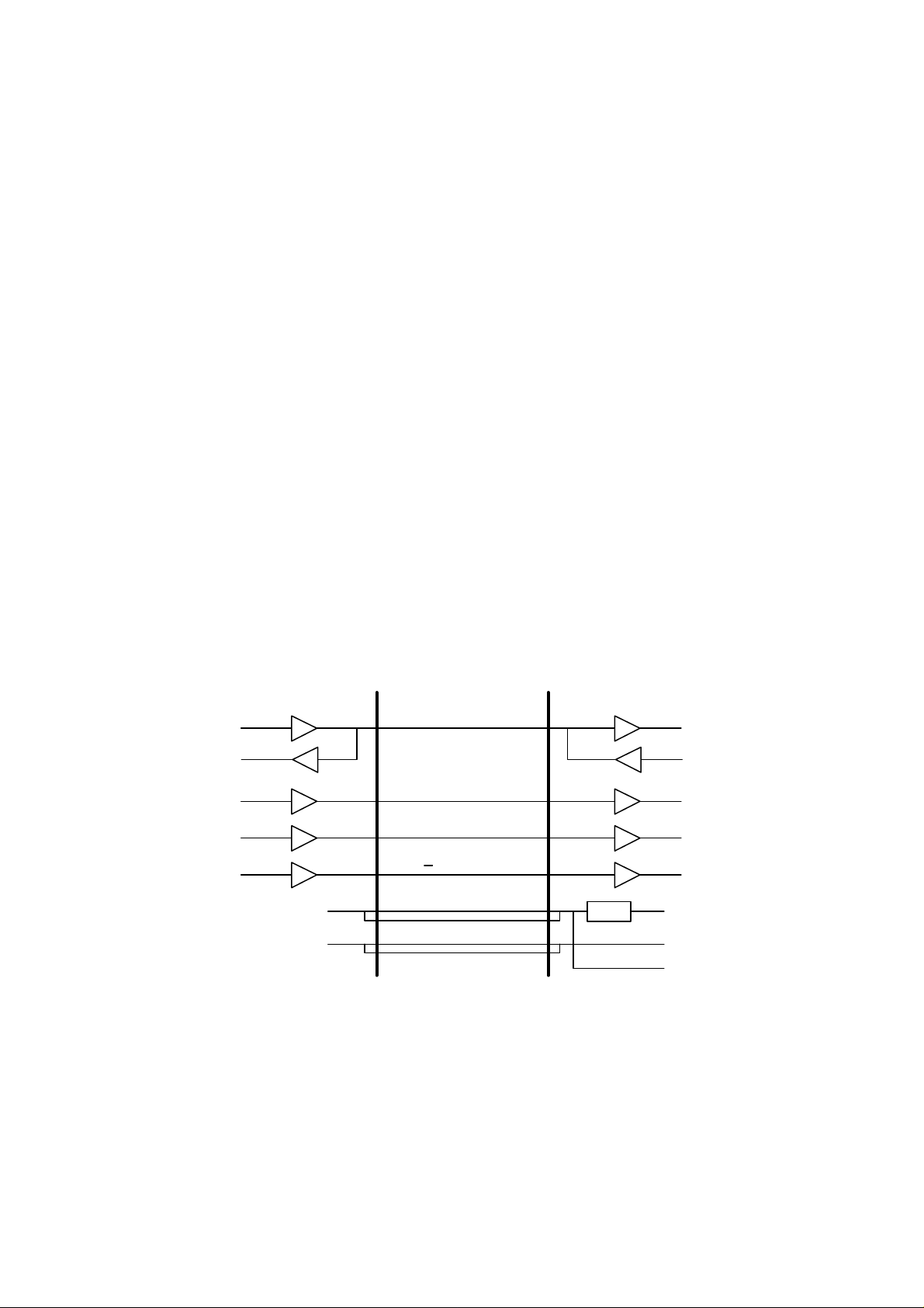
1.6 Communication with the Printer
A 3-line clock synchronous serial interface is used for communication between the
Mailbox unit and the printer.
The diagram below describes the timing of communications.
Printer Duplex unit
DATAOUT
DATAIN
CLKOUT
/ATNOUT
/OPRST
+24V
GND
SIDATA
SICLK
/ATTN
/OP RESET
+24V
GND
Fig. 2.4
REG.
DATAIN
DATAOUT
CLKIN
/ATNIN
/RESET
+5V
GND
+24V
II-5
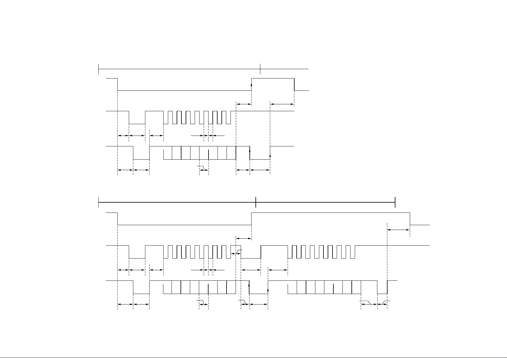
• Without a STATUS request
COMMAND transmission/receipt sequence
/ATTN
SICLK
500 min200 µs
II-6
400 min4µs
SIDATA
500 max
350 max
50 µs 12.8 µs
• Within a STATUS request
COMMAND transmission/receipt sequence
/ATTN
SICLK
400 min4µs
SIDATA
500 max
350 max
50 µs 350 max
6.4 min6.4 min
D0 D1 D2 D3 D4 D5 D6 D7
6.4 min
D0 D1 D2 D3 D4 D5 D6 D7
6.4 min
350 max
200 µs
350 max
200 µs
150 min
150 µs12.8 µs
STATUS transmission/receipt sequence
500 min
350 max
D0 D1 D2 D3 D4 D5 D6 D7
70 µs/1000 max 350 min

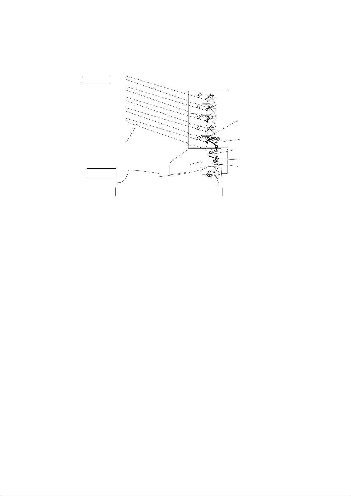
2. MECHANICS
r
2.1 General Overview of Mechanism
Paper Stoppe
Paper Stopper
#10 Bin
#9 Bin
#8 Bin
#7 Bin
#6 Bin
#5 Bin
#4 Bin
#3 Bin
MX-2002
Feed Roller A
Actuator A/B
Feed Roller B
Main Flap
Eject Roller
MX-2001
Feed Roller A
#2 Bin
#1 Bin
Eject Roller
Fig. 2.5
Actuator A/B
Feed Roller B
Main Flap
Actuator U
Feed Roller U
Flap U
Note:
The mechanical system of the MX-2003 is the same with the one of MX-2001/2002.
II-7

2.2 Paper Feed Sequence
This section describes the sequence when paper is fed from the printer to #1 bin as an
example.
(1) When the paper is sensed at the eject actuator in the fixing unit, the printer
specifies which bin of the Mailbox unit the paper is to be ejected to and sends the
command to start the operation of the Mailbox unit. (Refer to Fig. 2.6.)
When the Mailbox unit receives the command, it drives the feeding motor and
starts the timer to open the entrance flap (flap U).
MX-2001
HL-2060
Entrance Flap (Flap U)
Paper path
Eject actuator
Fixing Unit
Fig. 2. 6
(2) While the paper is being fed towards the entrance flap, the Mailbox unit starts
driving the entrance solenoid (solenoid U) and turns on the entrance flap so that
the paper is fed to the Mailbox unit. (Refer to Fig. 2.7.)
If the entrance sensor has not turned on after a specified time has passed, it
detects that a paper jam has occurred.
MX-2001
HL-2060
Entrance Flap (Flap U)
Paper path
Fig. 2. 7
II-8
(3) The Mailbox unit drives the #1 bin solenoid (solenoid A) and sets the #1 bin flap
(
)
(main flap) so that the paper is fed to #1 bin. (Refer to Fig. 2.8.)
If the eject sensor of #1 bin has not turned on after a specified time has passed, it
detects that a paper jam has occurred.
MX-2001
#1 Bin Actuator
(Actuator A/B)
Main Flap
HL-2060
#1 Bin
#1 Bin Flap
Entrance Actuator
(Actuator U)
Feed Motor U
Paper path
Fig. 2. 8
(4) After the paper end is ejected from the printer to the Mailbox unit, the printer sends
the command to stop the entrance solenoid to the unit. As soon as the Mailbox
unit receives the command, it stops driving the entrance solenoid.
(5) After the paper is correctly ejected into the #1 bin, the printer sends the command
to stop the operation of the Mailbox unit. As soon as the Mailbox unit receives the
command, it stops driving the feeding motor and the #1 bin solenoid.
II-9
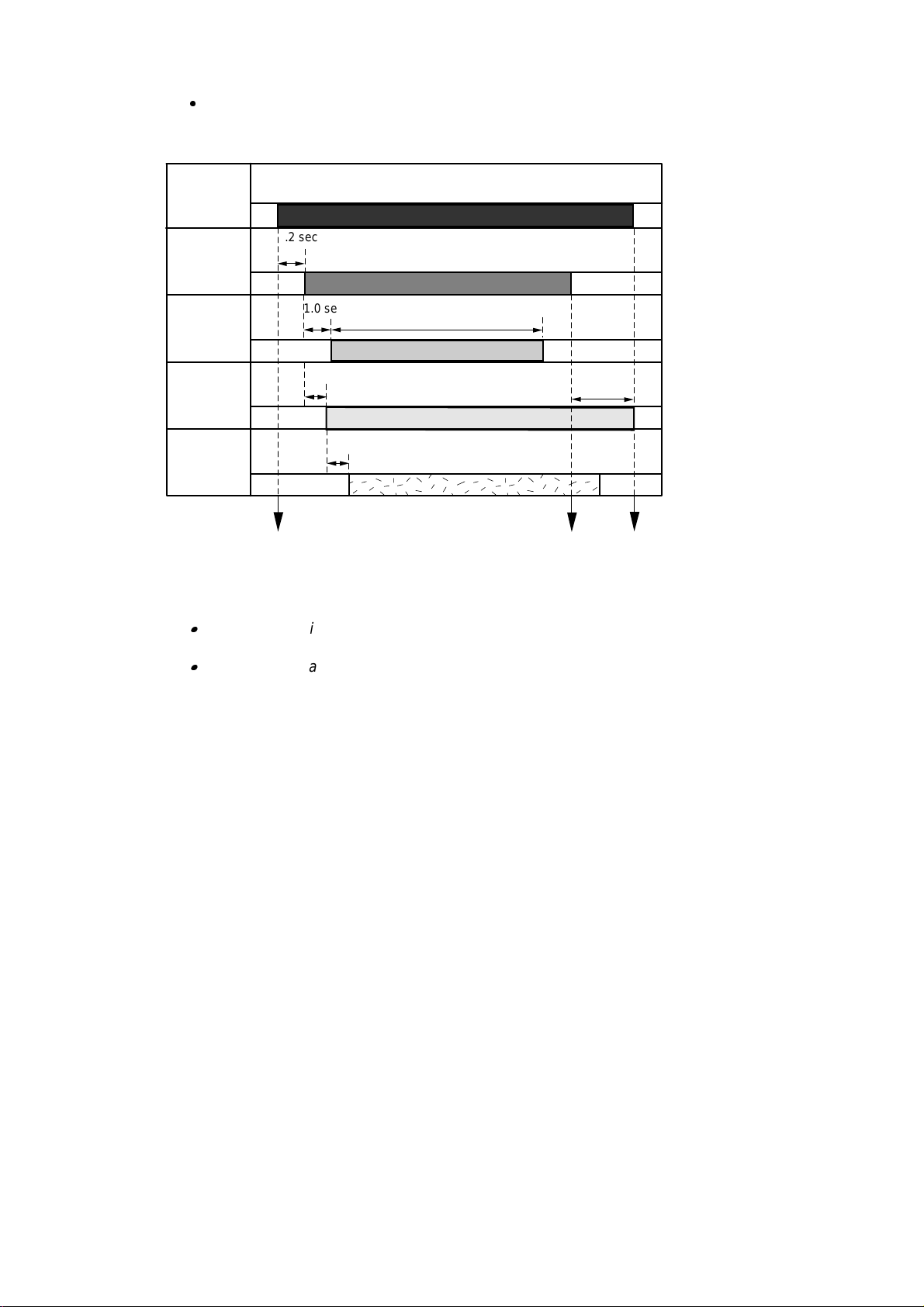
Paper Feed Timing Chart
<Example: #1 Bin >
Feeding
motor
Entrance
1.2 sec
solenoid
Entrance
1.0 sec
2.5 sec
sensor
#1 bin
0.7 sec
4.0 sec
solenoid
#1 bin eject
0.7 sec
sensor
The command to start the
operation received
The command to stop the
entrance solenoid received
Fig. 2.9
The command to stop the
operation received
Note:
The above timing applies to the 20ppm mode. It takes twice as long when the printer
is in the 10ppm (1200 dpi) mode.
The timing delay to eject the paper into the next bin upwards is about 0.3 seconds
later than the bin below because the distance between each bin is 39mm. Also, note
that the distance between the #5 bin and the #6 bin is 55mm and the timing is 0.43
seconds later.
II-10

CHAPTER III DISASSEMBLY
1. SAFETY PRECAUTIONS
To avoid creating secondary problems by mishandling, be careful to follow the following
precautions during maintenance work.
(1) Always unplug the power cord from the power outlet of the Mailbox unit before
accessing any parts inside the unit.
(2) Be careful not to lose screws, washers, or other parts removed during servicing.
(3) Be sure to apply grease to the gears and applicable positions specified in this chapter.
(4) When using soldering irons or other heat-generating tools, take care not to accidentally
damage parts such as wires, PCBs and covers.
(5) Before handling any PCBs, touch a metal portion of the equipment to discharge any
static electricity charge on your body, or the electronic parts or components may be
damaged.
(6) When transporting PCBs, be sure to wrap them in the correct protective packaging.
(7) Be sure to replace self-tapping screws correctly, if removed. Unless otherwise
specified, tighten screws to the following torque values.
TAPTITE, CUP B
M3 : 7kgf • cm
M4 : 10kgf • cm
TAPTITE, CUP S
M3 : 8kgf • cm
SCREW
M3 : 8kgf • cm
(8) When connecting or disconnecting cable connectors, hold the connector body, not the
cables. If the connector has a lock, release the connector lock first to release it.
(9) After a repair, check not only the repaired portion but also all connectors. Also check
that other related portions are functioning properly before operational checks.
III-1
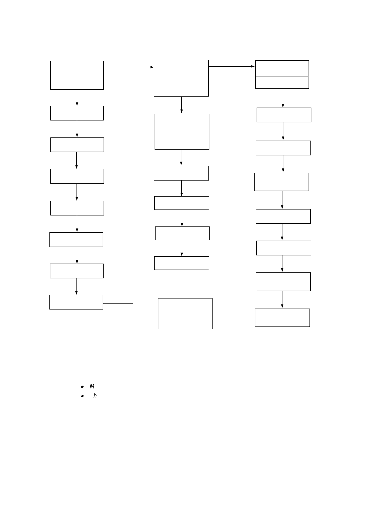
2. DISASSEMBLY FLOW
3.1 External
Covers
Cover UR
(MX-2001/2003 only)
Cover UL
(MX-2001/2003 only)
Cover R
Cover L
Rear Cover U ASSY
(MX-2001/2003 only)
Rear Cover A ASSY
3.1.1
3.1.2
3.1.3
3.1.4
3.1.5
3.1.6
3.2 Remove the
Main Frame Unit
from the Under
Frame Unit
(MX-2001/2003 only)
3.4 Under
Frame Unit
(MX-2001/2003 only)
Actuator U
Solenoid U
Photo Interrupter
Feed Roller U ASSY
3.4.1
3.4.2
3.4.3
3.4.4
3.3 Main Frame
Unit
I/F PCB A(B//C/D)
ASSY
Feeding Motor ASSY
Main PCB A(B)
ASSY
Solenoid A/B &
LED PCB ASSY
(MX-2001/2003 only)
Sensor PCB ASSY
Actuator A/B
3.3.1
3.3.2
3.3.3
3.3.4
3.3.5
3.3.6
3.4.5
PCB Cover A(B/D)
3.1.7
Flap U
Eject Roller ASSY
& Feed Roller
A/B ASSY
Bin
3.1.8
3.5 Remove the
Upper Unit from
the Lower Unit
(MX-2003 only)
Eject Pinch Roller
ASSY & Discharging
Brush
Note:
1) When disassembling the MX-2003, see Section 3.5 first to remove the upper unit from the
lower unit.
2) Most of the parts are common or similar among the MX-2001, the MX-2002 and the MX2003, and the procedures to disassemble them are also the same. Therefore;
MX-2001 is used for the figures in the following sections.
The parts name descriptions such as ‘Main PCB A(B)’ indicates ‘Main PCB A’ for MX2001 and ‘Main PCB B’ for MX-2002 in this chapter.
3.3.7
3.3.8
III-2

3. DISASSEMBLY PROCEDURE
,
3.1 External Covers
3.1.1 Cover UR (For MX-2001/2003 only)
(1) Remove the two screw cover sheets, then remove the two M3x6 Taptite screws.
(2) Remove the cover UR from the frame UR.
Frame UR
Taptite, M3x6
Screw Cover Sheet
Cover UR
Fig. 3.1
3.1.2 Cover UL (For MX-2001/2003 only)
(1) Remove the two screw cover sheets, then remove the two M3x6 Taptite screws.
(2) Remove the cover UL from the frame UL.
Taptite, M3x6
Screw Cover Sheet
Taptite
M3x6
Screw Cover Sheet
Frame UL
Taptite, M3x6
Screw Cover Sheet
Fig. 3.2
Cover UL
III-3
3.1.3 Cover R
(1) Unstick the upper sheet.
(2) Remove the one screw cover sheet, then remove the one M3x6 Taptite screw.
(3) Incline the cover R outwards using the two hooks as supporting points, then remove
the cover R.
Upper Sheet
Cover R
Taptite, M3x6
Screw Cover Sheet
3.1.4 Cover L
(1) Remove the one screw cover sheet L, then remove the one M3x6 Taptite screw.
(2) Incline the cover L outwards using the two hooks as supporting points, then remove
the cover L.
Taptite, M3x6
Screw Cover Sheet L
hook
Fig. 3.3
Cover L
hook
Fig. 3.4
Note:
When refitting cover L, ensure that the cover is lift fully upwards to reduce the gap on the
upper side of the cover.
III-4

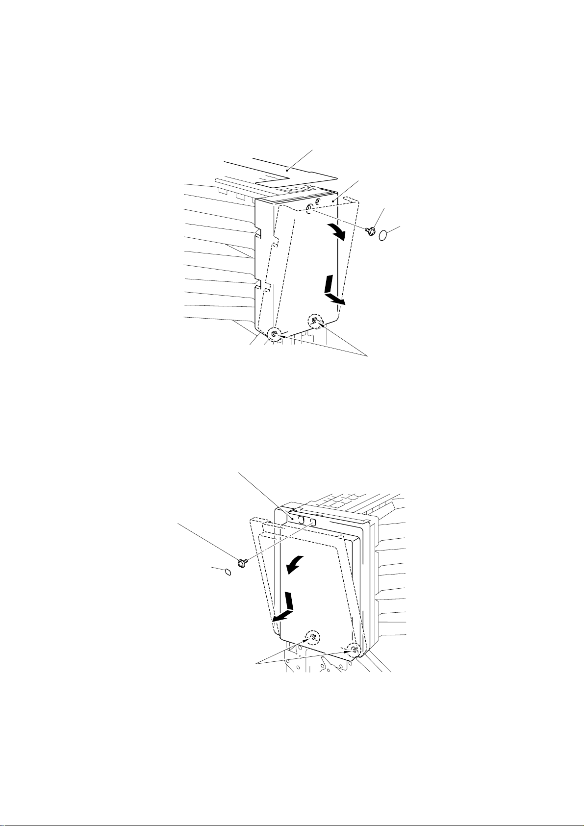
3.1.5 Rear Cover U ASSY (For MX-2001/2003 only)
(1) Release the two hooks to open the rear cover U ASSY.
hook
Rear Cover U ASSY
Fig. 3.5
(2) Release the left hand side of the cover by pulling the hinge of the frame UR outwards,
then remove the cover from the right hand side.
hook
Frame UL
Frame UR
hinge
Rear Cover U ASSY
Fig. 3.6
III-5
 Loading...