


R
MAILBOX UNIT
FOR LASER PRINTER
SERVICE MANUAL
MODEL:MX-2001 / MX-2002 / MX-2003
Note:
While the MX-2001 Mailbox unit is available in all countries, the MX-
2003 is available in U.S. and Canada only, and the MX-2002 is
available in the other countries than U.S. and Canada.
Oct., 1998
54T050NE0

© Copyright Brother 1998
All rights reserved.
No part of this publication may be reproduced in any form or by any means without permission in
writing from the publisher.
Specifications are subject to change without notice.
Trademarks:
The brother logo is a registered trademark of Brother Industries, Ltd.
Apple, the Apple Logo, and Macintosh are trademarks, registered in the United States and other
countries and True Type is a trademark of Apple computer, Inc.
Epson is a registered trademark and FX-80 and FX-850 are trademarks of Seiko Epson
Corporation.
Hewlett Packard is a registered trademark and HP Laser Jet is a trademark of Hewlett Packard
Company.
IBM, IBM PC and Proprinter are registered trademarks of International Business Machines
Corporation.
Microsoft and MS-DOS are registered trademarks of Microsoft Corporation.
Windows is a registered trademark of Microsoft Corporation in the U.S. and other countries.

PREFACE
This service manual contains basic information required for after-sales service of the optional
Mailbox unit, MX-2001/MX-2002/MX-2003 for the HL-2060 laser printer (hereinafter referred to as
“this unit” or "the Mailbox unit"). This information is vital to the service technician to maintain the
high performance of the unit.
This service manual covers the MX-2001 / MX-2002 / MX-2003 Mailbox units.
The manual consists of the following chapters:
CHAPTER I : GENERAL
General view, specifications, etc.
CHAPTER II : THEORY OF OPERATION
Basic operation of the electrical system and the mechanical system
CHAPTER III : DISASSEMBLY
Procedures for disassembling the mechanical system.
CHAPTER IV : TROUBLESHOOTING
Reference values and adjustments, troubleshooting malfunctions, etc.
APPENDICES :
Information in this manual is subject to change due to improvement or re-design of the product. All
relevant information in such cases will be supplied in service information bulletins (Technical
Information).
A thorough understanding of this unit, based on information in this service manual and service
information bulletins, is required for maintaining its performance and for improving the practical
ability to find the cause of problems.
PCB CIRCUIT DIAGRAMS, ETC.

CONTENTS
CHAPTER I GENERAL............................................................................I-1
1. INSTRUCTIONS..........................................................................................................I-1
2. OVERVIEW.................................................................................................................I-2
3. SPECIFICATIONS.......................................................................................................I-3
3.1 Functions...............................................................................................................................I-3
3.2 Electrical and Mechanical .....................................................................................................I-3
3.3 Paper.....................................................................................................................................I-4
CHAPTER II THEORY OF OPERATION.................................................II-1
1. ELECTRONICS.........................................................................................................II-1
1.1 General Block Diagram...................................................................................................II-1
1.2 Main PCB........................................................................................................................II-3
1.2.1 CPU...............................................................................................................................II-3
1.2.2 Bin solenoid drive circuit................................................................................................II-3
1.2.3 Entrance solenoid drive circuit ......................................................................................II-3
1.2.4 Bin capacity sensor.......................................................................................................II-4
1.2.5 Infrared LED drive circuit...............................................................................................II-4
1.2.6 Power supply LED drive circuit......................................................................................II-4
1.3 I/F PCB ...........................................................................................................................II-4
1.3.1 Regulator.......................................................................................................................II-4
1.3.2 Serial I/F circuit..............................................................................................................II-5
1.3.3 Feeding motor drive circuit............................................................................................ II- 5
1.3.4 Entrance sensor input ................................................................................................... II-5
1.4 Sensor PCB....................................................................................................................II-5
1.5 Power supply LED PCB..................................................................................................II-5
1.6 Communication with the Printer......................................................................................II-5
2. MECHANICS.............................................................................................................II-7
2.1 General Overview of Mechanism....................................................................................II-7
2.2 Paper Feed Sequence....................................................................................................II-8
CHAPTER III DISASSEMBLY AND REASSEMBLY...............................III-1
1. SAFETY PRECAUTIONS.........................................................................................III-1
2. DISASSEMBLY FLOW.............................................................................................III-2
3. DISASSEMBLY PROCEDURE ................................................................................III-3
3.1 External Covers.............................................................................................................III-3
3.1.1 Cover UR (For MX-2001/2003 only)............................................................................. III-3
3.1.2 Cover UL (For MX-2001/2003 only) ............................................................................. III-3
3.1.3 Cover R........................................................................................................................III-4
3.1.4 Cover L.........................................................................................................................III-4
3.1.5 Rear Cover U ASSY (For MX-2001/2003 only)............................................................ III-5
3.1.6 Rear Cover A ASSY.....................................................................................................III-7
i

3.1.7 PCB Cover A (MX-2001) / PCB Cover B (MX-2002) / PCB Cover D (MX-2003 Upper
Unit)..............................................................................................................................III-8
3.1.8 Bin................................................................................................................................III-8
3.2 Remove the Main Frame Unit from the Under Frame Unit (For MX-2001/2003 only).III-10
3.3 Main Frame Unit ..........................................................................................................III-10
3.3.1 I/F PCB A ASSY (MX-2001) / I/F PCB B ASSY (MX-2002) / I/F PCB C ASSY (MX-2003
Lower Unit) / I/F PCB D ASSY (MX-2003 Upper Unit) ............................................... III-10
3.3.2 Feeding Motor ASSY.................................................................................................. III-11
3.3.3 Main PCB A ASSY (MX-2001, MX-2003 Lower Unit) / Main PCB B ASSY (MX-2002,
MX-2003 Upper Unit)..................................................................................................III-12
3.3.4 Solenoid A/B & LED PCB ASSY (MX-2001/2003 only)..............................................III-13
3.3.5 Sensor PCB ASSY.....................................................................................................III-14
3.3.6 Actuator A/B...............................................................................................................III-15
3.3.7 Eject Roller ASSY / Feed Rollers A/B ASSY..............................................................III-17
3.3.8 Eject Pinch Roller ASSY & Discharging Brush........................................................... III-19
3.4 Under Frame Unit (For MX-2001/2003 only)...............................................................III-20
3.4.1 Actuator U ..................................................................................................................III-20
3.4.2 Solenoid U..................................................................................................................III-21
3.4.3 Photo Interrupter ........................................................................................................III-21
3.4.4 Feed Roller U ASSY................................................................................................... III-22
3.4.5 Flap U.........................................................................................................................III-23
3.5 Remove the Upper Unit from the Lower Unit (For MX-2003 only)...............................III-24
3.6 Packing of MX-2003.....................................................................................................III-28
4. APPLICATION OF GREASE..................................................................................III-29
4.1 Rollers..........................................................................................................................III-29
4.1.1 Feed Roller A/B ASSY................................................................................................III-29
4.1.2 Eject Roller ASSY ......................................................................................................III -29
4.1.3 Feed Roller U ASSY................................................................................................... III-30
4.1.4 Pressure Roller / Pressure Roller U...........................................................................III-30
4.2 Gears...........................................................................................................................III-31
4.2.1 Gears on the Main Frame R.......................................................................................III-31
4.2.2 Gears on the Main Frame L........................................................................................III-31
4.2.3 Gears on the Frame UR.............................................................................................III-32
4.3 Others..........................................................................................................................III-32
CHAPTER IV TROUBLESHOOTING...................................................... IV-1
1. INITIAL CHECK ......................................................................................................IV-1
2. MTBF / MTTR .........................................................................................................IV-2
3. TROUBLESHOOTING............................................................................................ IV-3
APPENDICES
1. MAIN PCB CIRCUIT DIAGRAM (1/2).......................................................................A-1
2. MAIN PCB CIRCUIT DIAGRAM (2/2).......................................................................A-2
3. I/F PCB CIRCUIT DIAGRAM....................................................................................A-3
INDEX
ii
CHAPTER I GENERAL
1. INSTRUCTIONS
The MX-2001/2002/2003 Mailbox units are optionally installed onto the HL-2060 printer.
The MX-2001 Lower Mailbox unit consists of five bins. The MX-2002 Upper Mailbox
unit is additionally installed onto the MX-2001, and also consists of five bins. The MX2003 Mailbox unit consists of ten bins.
Note: While the MX-2001 Mailbox unit is available in all countries, the MX-2003 is
available in U.S. and Canada only, and the MX-2002 is available in the other
countries than U.S. and Canada.
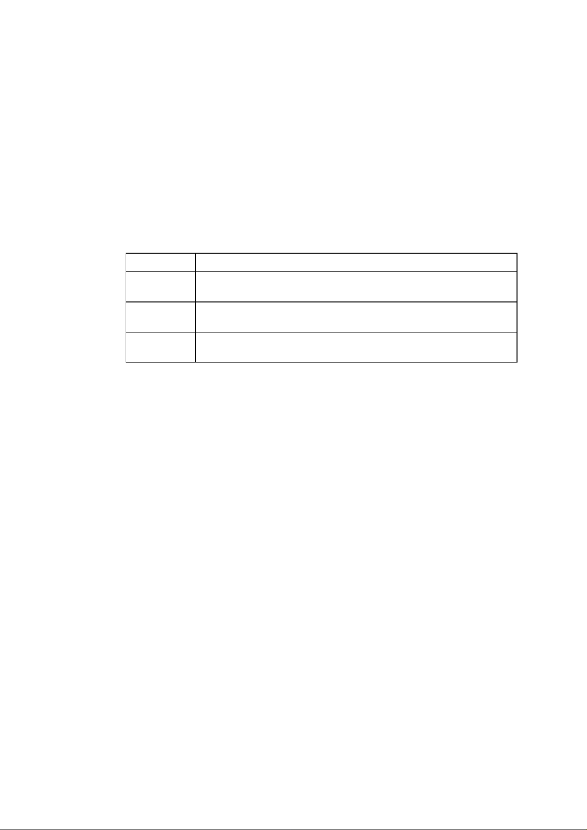
The unit works as a
for each function.
Function Description
Stacker
Sorter
Mailbox
When you install the unit onto the printer, the printed paper is ejected to the output tray
of the printer and/or the bin(s) of the Mailbox unit by selection commands sent from the
printer.
stacker, sorter
Printed paper is ejected into the multiple bins behaving as a single
high-capacity tray.
Printed paper is ejected as a set for a print job into a bin when multiple
sets of documents are printed and collated.
Printed paper is ejected into the specific bin defined as your own mail
box.
and
mailbox
for the printer. See the table below
I-1
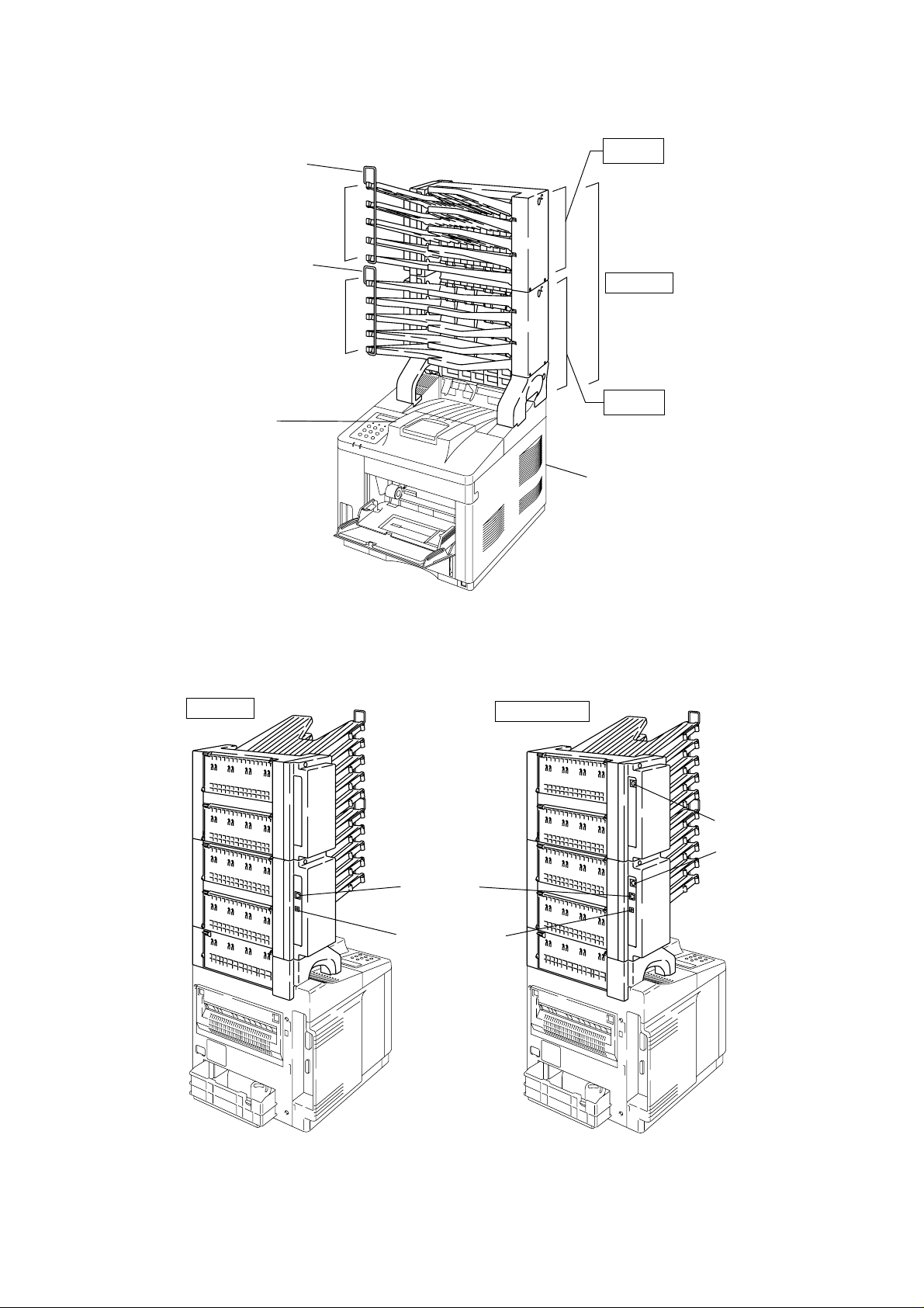
2. OVERVIEW
<Front View>
Printer Output
Paper Stopper
MX-2002
Bin 6 - 10
Paper Stopper
MX-2003
Bin 1 - 5
MX-2001
Tray
HL-2060 Printer
<Rear View>
MX-2003
Fig. 1.1
Modular jack
DC jack connector
MX-2001/2002
Mini DIN connector
Mini DIN connector
Fig. 1.2
I-2

3. SPECIFICATIONS
3.1 Function
(1) Stacking direction
Face down
(2) Feeding speed (when feeding A4 size paper)
Printer Mode When the paper is ejected into
multiple bins
20ppm mode 18 ppm 20 ppm
10ppm mode 9 ppm 10 ppm
(3) Bin capacity
Normal mode: 100 sheet/bin
Big stacker mode*: 300 sheet/bin
* When bins #2, #4, #7 and/or #9 are removed, bins #1, #3, #6 and/or #8 bin(s) as big
stacker bins with a capacity of 300 sheets each.
3.2 Electrical / Mechanical
(1) Power source
AC 100 to 240V, 50Hz/60Hz
When the paper is ejected
continuously into a single bin
(2) Power consumption
Printing: 25W or less (when MX-2001 is installed.)
45W or less (when both MX-2001 and MX-2002, or MX-2003 are
installed.)
Stand-by: 15W or less (when MX-2001 is installed.)
20W or less (when both MX-2001 and MX-2002, or MX-2003 are
installed.)
(3) Temperature
Operating: 10 to 32.5°C (50 to 90.5°F)
Storage: 0 to 40°C (38 to 104°F)
(4) Humidity
Operating: 20 to 80% (non condensing)
Storage: 10 to 85% (non condensing)
(5) Dimensions
MX-2001: 354 (W) x 356 (D) x 411 (H) mm
MX-2002: 354 (W) x 356 (D) x 337 (H) mm
MX-2003: 354 (W) x 356 (D) x 617 (H) mm
(6) Weight
MX-2001: Approx. 5.2 kg
MX-2002: Approx. 4.1 kg
MX-2003: Approx. 9.3 kg
I-3

3.3 Paper
(1) Paper type
Cut sheet
Normal paper / Specific recycled paper
*Special paper is not included.
(2) Feedable paper weight
60 ~ 90 g/m
2
(16 ~ 24lb.)
(3) Feedable paper thickness
0.075 ~ 0.12 mm
(4) Paper size
A4, Letter, Executive, ISO B5
(5) Recommended paper
Xerox 4200 (For U.S.) / RANK Xerox 80 g/m
2
Premier paper (For Europe)
I-4

CHAPTER II THEORY OF OPERATION
1. ELECTRONICS
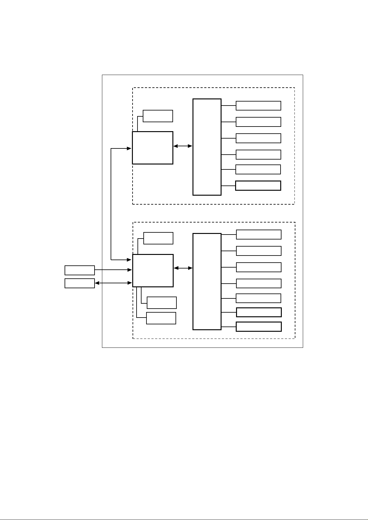
1.1 General Block Diagram
<MX-2001 & MX-2002>
The MX-2001 Mailbox unit is operated according to signals sent from the printer by serial
communication. The MX-2001 and MX-2002 also communicate with each other by serial
communication. Refer to Fig. 2.1 which shows the general block diagram of the MX-2001
and MX-2002.
<MX-2002>
Feeding
Motor
#10 bin solenoid
#9 bin solenoid
Adapter
Printer
Communication
Serial
+24V Input
Serial
Communication
I/F PCB
<MX-2001>
Feeding
Motor
I/F PCB
Entrance
Solenoid
Entrance
Sensor
Main PCB
Main PCB
#8 bin solenoid
#7 bin solenoid
#6 bin solenoid
Sensor PCB
#5 bin solenoid
#4 bin solenoid
#3 bin solenoid
#2 bin solenoid
#1 bin solenoid
Sensor PCB
LED PCB
Fig. 2.1
Note:
The following parts and circuits are not fitted on the PCBs in the MX-2002.
<Main PCB>
Entrance solenoid circuit
LED PCB circuit
<I/F PCB>
Entrance sensor circuit
DC jack connector for the adapter
Modular jack connection to the printer
II-1
<MX-2003>
The electronic system of the MX-2003 is basically the same with the one of MX2001/2002. Refer to Fig. 2.2 which shows the general block diagram of the MX-2003.
<MX-2003>
<Upper Unit>
#10 bin solenoid
Feeding
Serial
Communica-
tion
Motor
I/F PCB
Main PCB
#9 bin solenoid
#8 bin solenoid
#7 bin solenoid
#6 bin solenoid
Sensor PCB
Adapter
Printer
+24V Input
Serial
Communica-
tion
<Lower Unit>
Feeding
Motor
I/F PCB
Entrance
Solenoid
Entrance
Sensor
Fig. 2.2
Main PCB
#5 bin solenoid
#4 bin solenoid
#3 bin solenoid
#2 bin solenoid
#1 bin solenoid
Sensor PCB
LED PCB
II-2

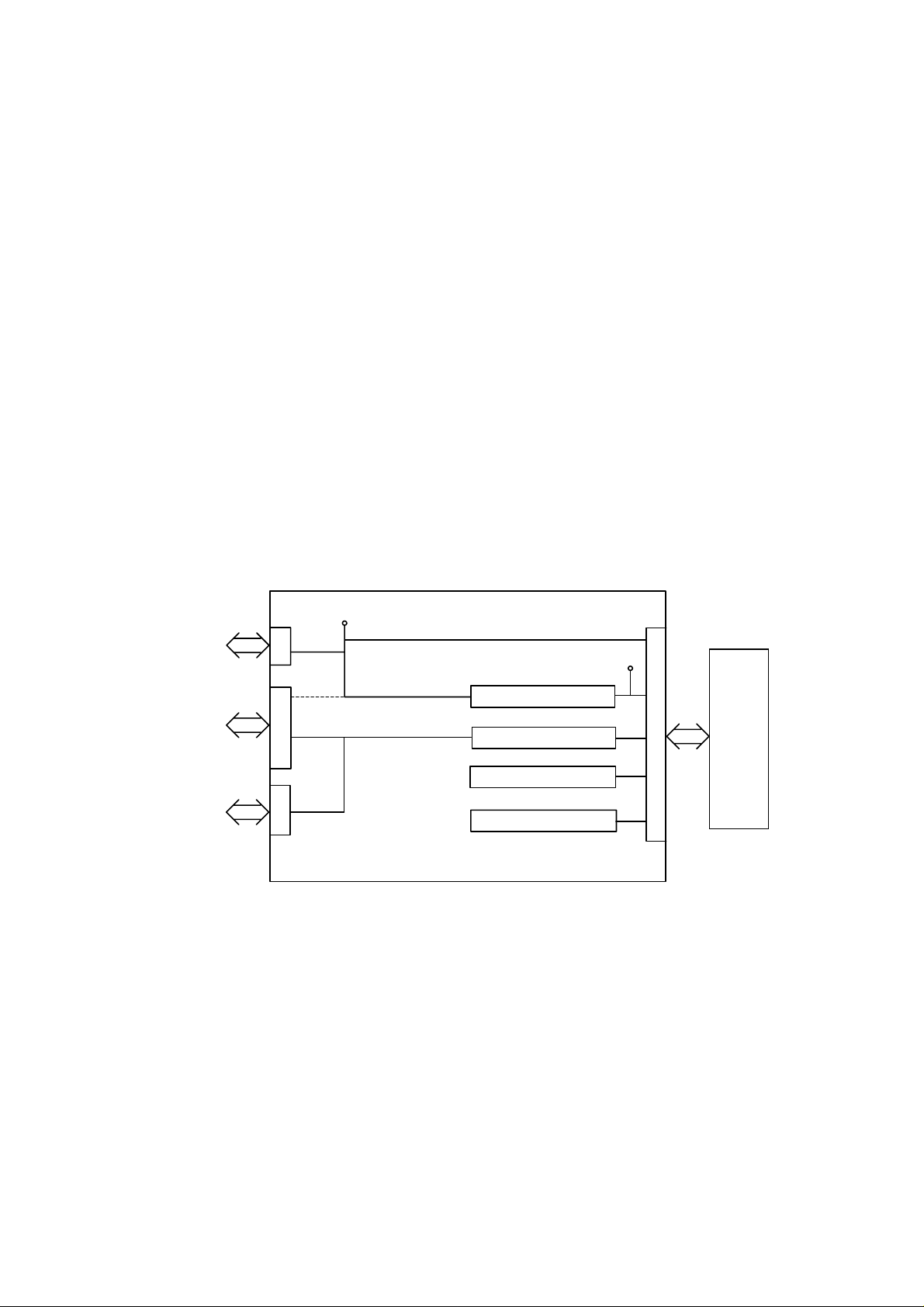
1.2 Main PCB
Fig. 2.2 shows the block diagram of the main PCB.
I/F PCB
+24V
+5V
Entrance solenoid drive circuit
GND
Main PCB
M50727
CPU
Bin solenoid drive circuit
(for each bin)
Bin capacity sensor
(for each bin)
Infrared LED drive circuit
Power supply LED drive circuit
Printer
Fig. 2.2
1.2.1 CPU
The CPU M50727 is a 4 bit one-chip microcomputer which controls the Mailbox unit and
communicates with the printer using serial communications. According to the commands
from the printer, the CPU drives the feeding motor and the solenoid of each bin and then
feeds the paper to the specified bin. If it detects paper full in the specified bin, the CPU
sends the signal to the printer.
1.2.2 Bin solenoid drive circuit
The bin solenoid drive circuit drives the solenoid of each bin which controls the diverter
flap to send the paper to each bin. The diverter flap is opened when the solenoid is
energized and the flap is closed when the solenoid is de-energized. Each drive circuit for
each of the five bins works independently.
This circuit provides a constant current drive to the solenoid. The solenoid is driven at
600mA for 200msec when it is first energized and then it is held by being driven at
150mA.
1.2.3 Entrance solenoid drive circuit
The entrance solenoid drive circuit drives the solenoid which controls the flap to switch
the paper eject tray from the printer to the Mailbox unit. It is the same as the bin solenoid
drive circuit and connected to the entrance solenoid through the I/F PCB.
II-3
1.2.4 Bin capacity sensor
The bin capacity sensors, which are five infrared LEDs, detect whether the bin is full or
not.
The infrared sensor output generated from the sensor PCB is shut off when the bin is full
of paper. The CPU recognizes that the bin is full when the infrared sensor output is shut
off for 20 seconds.
These sensors also detect paper jams. When paper is ejected into the bin, the sensor is
covered temporarily by the actuator. The CPU recognizes that a paper jam has occurred
when the sensor has not cleared after a specified time has passed.
1.2.5 Infrared LED drive circuit
The infrared LED drive circuit drives the five infrared LEDs on the sensor PCB. This
drive circuit is controlled by the CPU.
1.2.6 Power supply LED drive circuit
The power supply LED drive circuit drives the power supply LED when the regulated DC
power, +24V, is supplied when the adapter is connected and plugged in.
1.3 I/F PCB
Fig. 2.3 shows the block diagram of the I/F PCB.
I/F PCB
+24V
Adapter
Printer
Mail Box Unit
+24V
+24V
Serial I/F drive circuit
Feeding motor drive circuit
Entrance sensor input
Fig. 2.3
+5V
Regulator
Main PCB
1.3.1 Regulator
The regulator generates and supplies the +5V logic power supply from the +24V supplied
by the adapter.
If the adapter is not connected, the regulator generates the +5V logic power supply from
the +24V supplied by the printer. In this case, the +24V supplied by the printer is not
connected with the +24V supply that should be provided to the Mailbox unit from the
adapter.
II-4
1.3.2 Serial I/F circuit
The serial interface circuit transmits and receives data to and from the printer.
1.3.3 Feeding motor drive circuit
The feeding motor drive circuit drives the motor which feeds the paper in the Mailbox unit
according to the signals from the CPU.
1.3.4 Entrance sensor input
The entrance sensor which is connected with the CPU detects whether the paper is fed
into the Mailbox unit or not.
1.4 Sensor PCB
The five infrared LEDs are mounted on the sensor PCB to detect whether the bin is full or
not. The sensor PCB is controlled according to signals from the CPU.
1.5 Power supply LED PCB
The LED which turns on when the +24V is supplied from the adapter is mounted on the
power supply LED PCB.
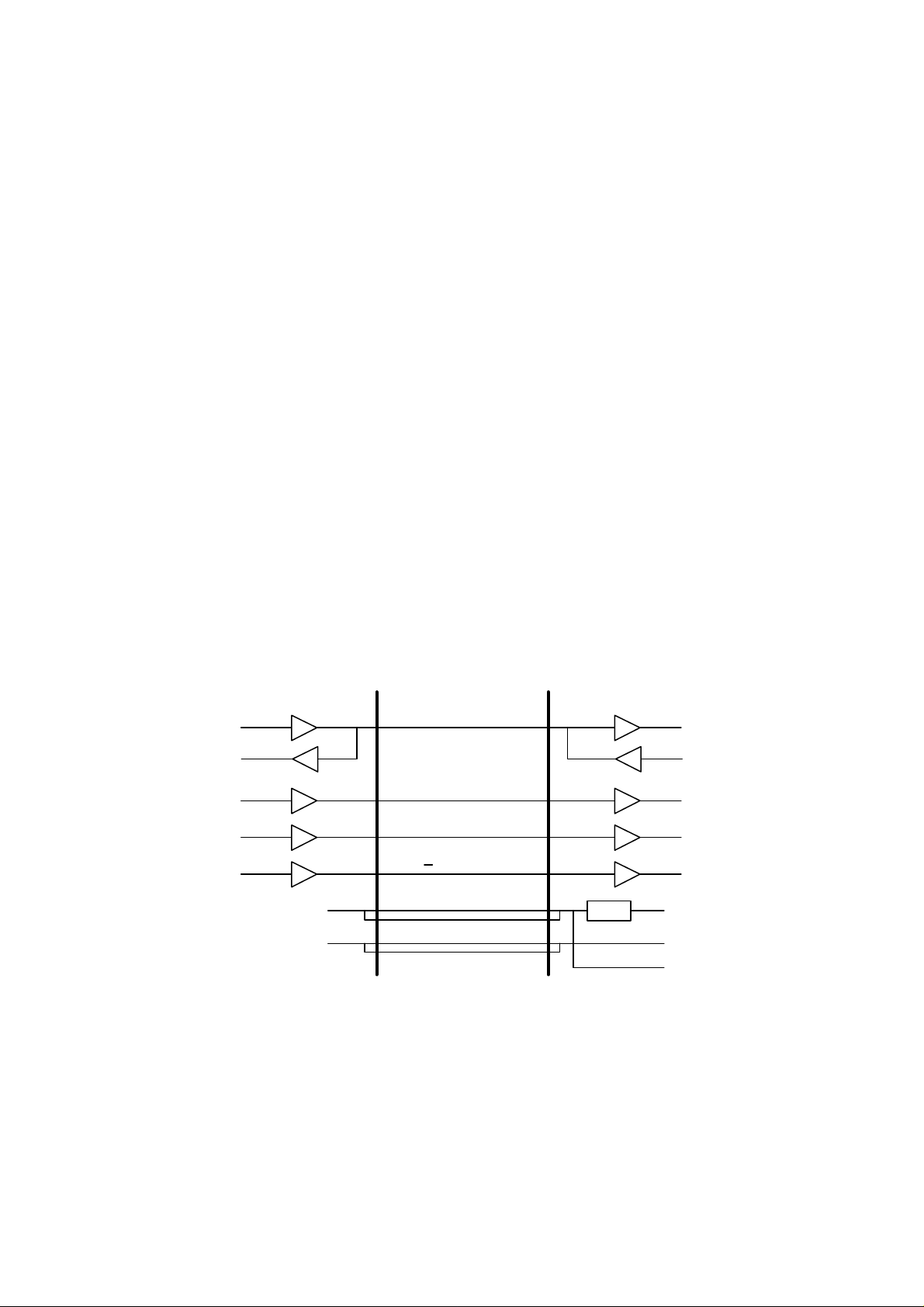
1.6 Communication with the Printer
A 3-line clock synchronous serial interface is used for communication between the
Mailbox unit and the printer.
The diagram below describes the timing of communications.
Printer Duplex unit
DATAOUT
DATAIN
CLKOUT
/ATNOUT
/OPRST
+24V
GND
SIDATA
SICLK
/ATTN
/OP RESET
+24V
GND
Fig. 2.4
REG.
DATAIN
DATAOUT
CLKIN
/ATNIN
/RESET
+5V
GND
+24V
II-5
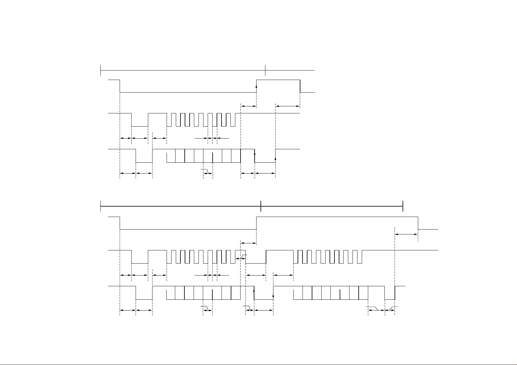
• Without a STATUS request
COMMAND transmission/receipt sequence
/ATTN
SICLK
500 min200 µs
II-6
400 min4µs
SIDATA
500 max
350 max
50 µs 12.8 µs
• Within a STATUS request
COMMAND transmission/receipt sequence
/ATTN
SICLK
400 min4µs
SIDATA
500 max
350 max
50 µs 350 max
6.4 min6.4 min
D0 D1 D2 D3 D4 D5 D6 D7
6.4 min
D0 D1 D2 D3 D4 D5 D6 D7
6.4 min
350 max
200 µs
350 max
200 µs
150 min
150 µs12.8 µs
STATUS transmission/receipt sequence
500 min
350 max
D0 D1 D2 D3 D4 D5 D6 D7
70 µs/1000 max 350 min

2. MECHANICS
r
2.1 General Overview of Mechanism
Paper Stoppe
Paper Stopper
#10 Bin
#9 Bin
#8 Bin
#7 Bin
#6 Bin
#5 Bin
#4 Bin
#3 Bin
MX-2002
Feed Roller A
Actuator A/B
Feed Roller B
Main Flap
Eject Roller
MX-2001
Feed Roller A
#2 Bin
#1 Bin
Eject Roller
Fig. 2.5
Actuator A/B
Feed Roller B
Main Flap
Actuator U
Feed Roller U
Flap U
Note:
The mechanical system of the MX-2003 is the same with the one of MX-2001/2002.
II-7

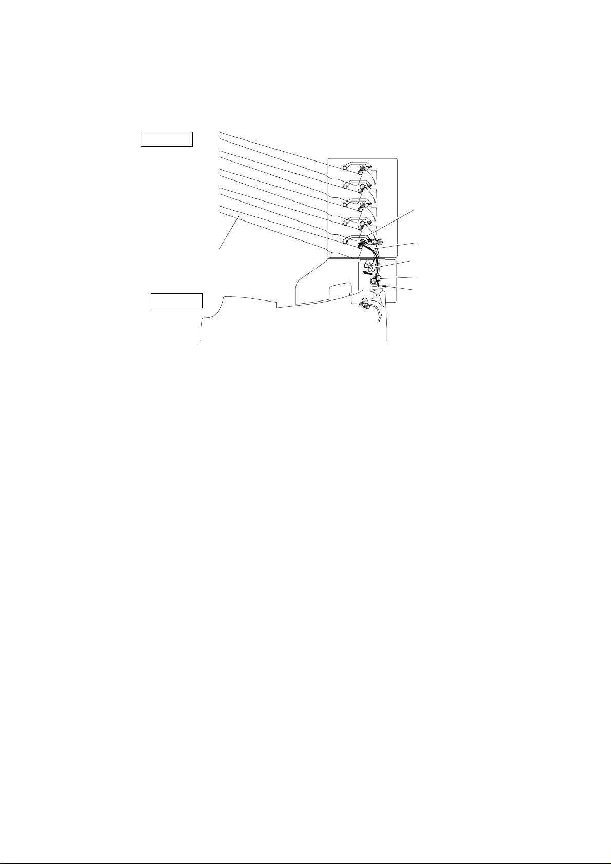
2.2 Paper Feed Sequence
This section describes the sequence when paper is fed from the printer to #1 bin as an
example.
(1) When the paper is sensed at the eject actuator in the fixing unit, the printer
specifies which bin of the Mailbox unit the paper is to be ejected to and sends the
command to start the operation of the Mailbox unit. (Refer to Fig. 2.6.)
When the Mailbox unit receives the command, it drives the feeding motor and
starts the timer to open the entrance flap (flap U).
MX-2001
HL-2060
Entrance Flap (Flap U)
Paper path
Eject actuator
Fixing Unit
Fig. 2. 6
(2) While the paper is being fed towards the entrance flap, the Mailbox unit starts
driving the entrance solenoid (solenoid U) and turns on the entrance flap so that
the paper is fed to the Mailbox unit. (Refer to Fig. 2.7.)
If the entrance sensor has not turned on after a specified time has passed, it
detects that a paper jam has occurred.
MX-2001
HL-2060
Entrance Flap (Flap U)
Paper path
Fig. 2. 7
II-8
(3) The Mailbox unit drives the #1 bin solenoid (solenoid A) and sets the #1 bin flap
(
)
(main flap) so that the paper is fed to #1 bin. (Refer to Fig. 2.8.)
If the eject sensor of #1 bin has not turned on after a specified time has passed, it
detects that a paper jam has occurred.
MX-2001
#1 Bin Actuator
(Actuator A/B)
Main Flap
HL-2060
#1 Bin
#1 Bin Flap
Entrance Actuator
(Actuator U)
Feed Motor U
Paper path
Fig. 2. 8
(4) After the paper end is ejected from the printer to the Mailbox unit, the printer sends
the command to stop the entrance solenoid to the unit. As soon as the Mailbox
unit receives the command, it stops driving the entrance solenoid.
(5) After the paper is correctly ejected into the #1 bin, the printer sends the command
to stop the operation of the Mailbox unit. As soon as the Mailbox unit receives the
command, it stops driving the feeding motor and the #1 bin solenoid.
II-9
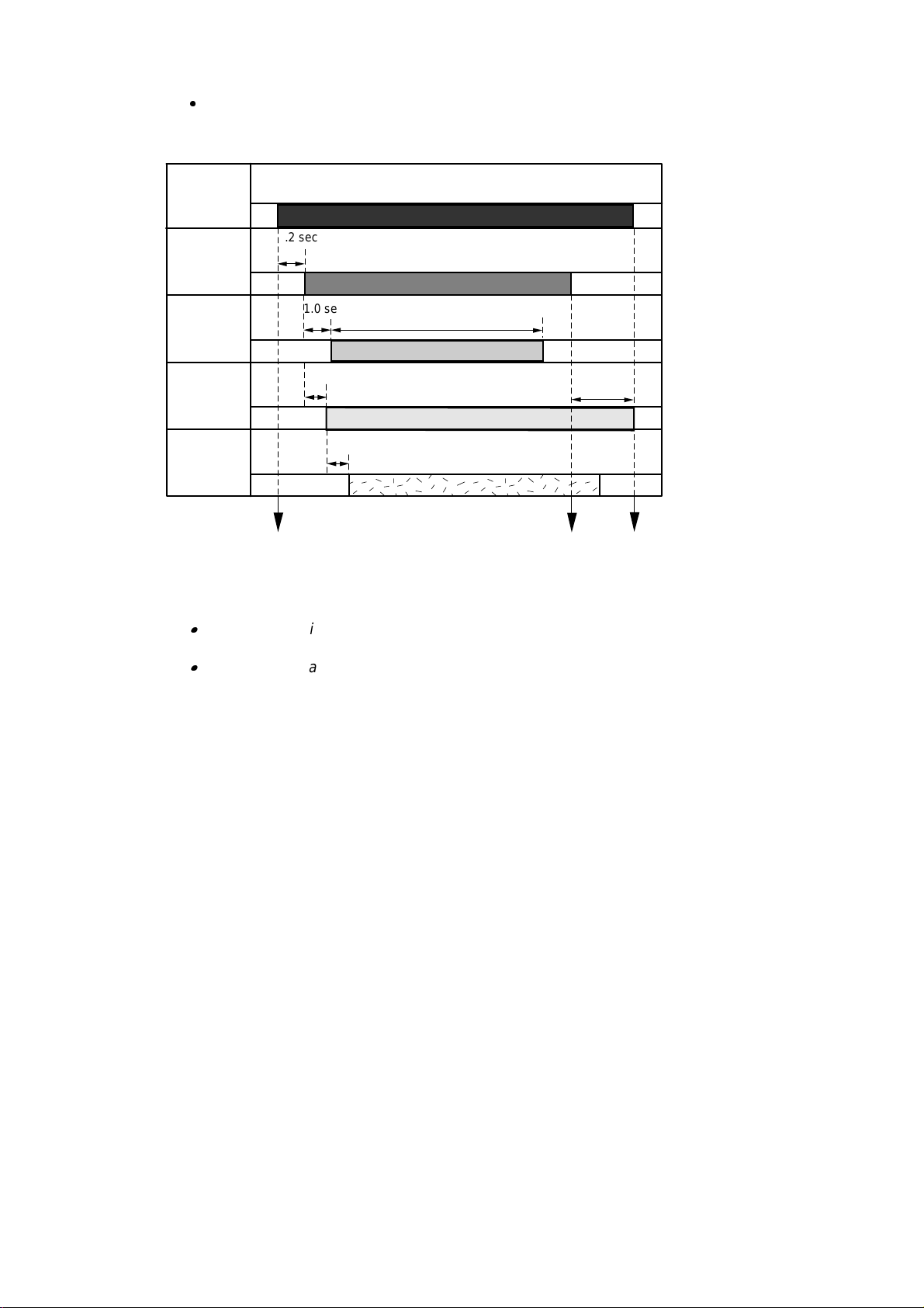
Paper Feed Timing Chart
<Example: #1 Bin >
Feeding
motor
Entrance
1.2 sec
solenoid
Entrance
1.0 sec
2.5 sec
sensor
#1 bin
0.7 sec
4.0 sec
solenoid
#1 bin eject
0.7 sec
sensor
The command to start the
operation received
The command to stop the
entrance solenoid received
Fig. 2.9
The command to stop the
operation received
Note:
The above timing applies to the 20ppm mode. It takes twice as long when the printer
is in the 10ppm (1200 dpi) mode.
The timing delay to eject the paper into the next bin upwards is about 0.3 seconds
later than the bin below because the distance between each bin is 39mm. Also, note
that the distance between the #5 bin and the #6 bin is 55mm and the timing is 0.43
seconds later.
II-10

CHAPTER III DISASSEMBLY
1. SAFETY PRECAUTIONS
To avoid creating secondary problems by mishandling, be careful to follow the following
precautions during maintenance work.
(1) Always unplug the power cord from the power outlet of the Mailbox unit before
accessing any parts inside the unit.
(2) Be careful not to lose screws, washers, or other parts removed during servicing.
(3) Be sure to apply grease to the gears and applicable positions specified in this chapter.
(4) When using soldering irons or other heat-generating tools, take care not to accidentally
damage parts such as wires, PCBs and covers.
(5) Before handling any PCBs, touch a metal portion of the equipment to discharge any
static electricity charge on your body, or the electronic parts or components may be
damaged.
(6) When transporting PCBs, be sure to wrap them in the correct protective packaging.
(7) Be sure to replace self-tapping screws correctly, if removed. Unless otherwise
specified, tighten screws to the following torque values.
TAPTITE, CUP B
M3 : 7kgf • cm
M4 : 10kgf • cm
TAPTITE, CUP S
M3 : 8kgf • cm
SCREW
M3 : 8kgf • cm
(8) When connecting or disconnecting cable connectors, hold the connector body, not the
cables. If the connector has a lock, release the connector lock first to release it.
(9) After a repair, check not only the repaired portion but also all connectors. Also check
that other related portions are functioning properly before operational checks.
III-1
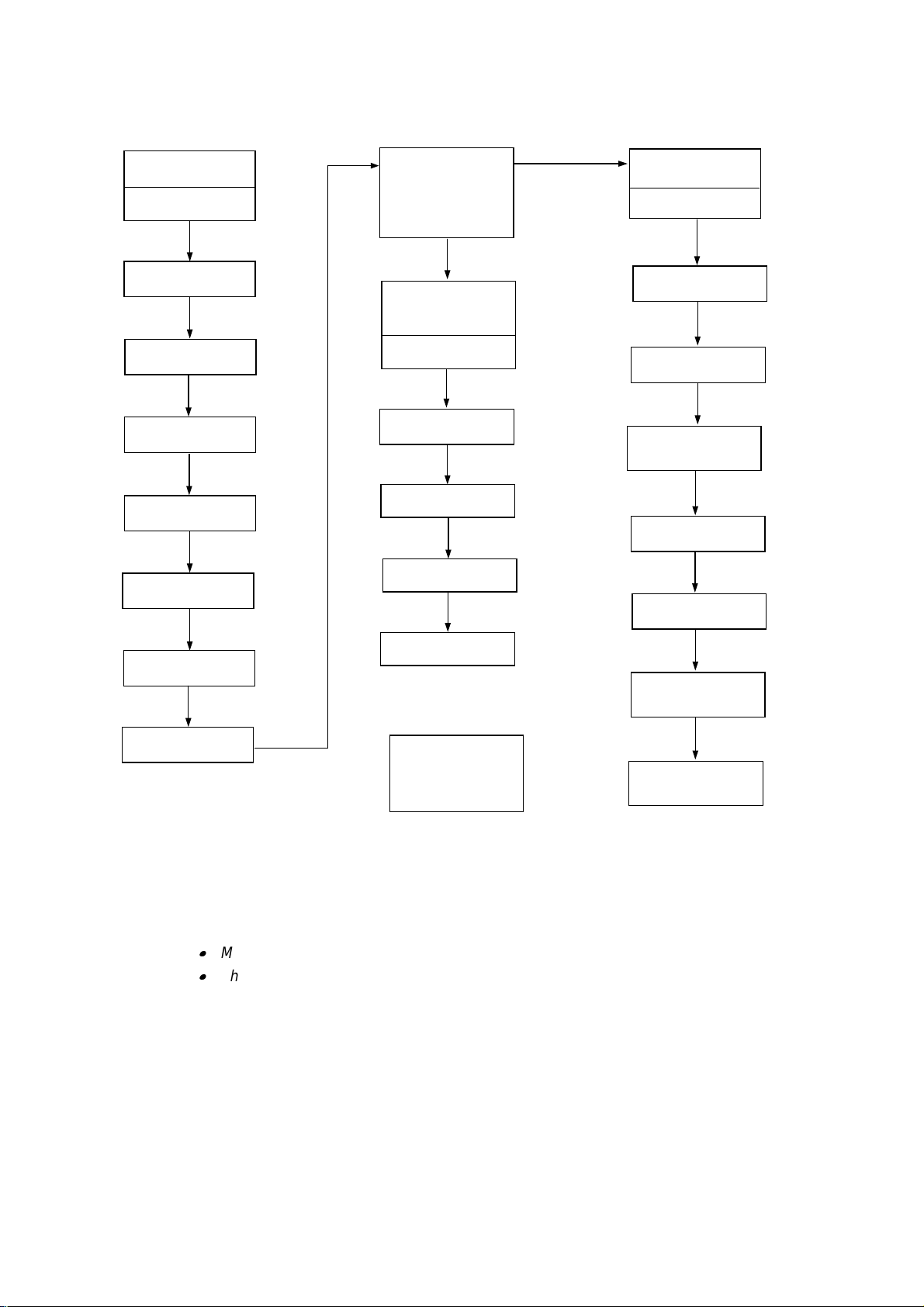
2. DISASSEMBLY FLOW
3.1 External
Covers
Cover UR
(MX-2001/2003 only)
Cover UL
(MX-2001/2003 only)
Cover R
Cover L
Rear Cover U ASSY
(MX-2001/2003 only)
Rear Cover A ASSY
3.1.1
3.1.2
3.1.3
3.1.4
3.1.5
3.1.6
3.2 Remove the
Main Frame Unit
from the Under
Frame Unit
(MX-2001/2003 only)
3.4 Under
Frame Unit
(MX-2001/2003 only)
Actuator U
Solenoid U
Photo Interrupter
Feed Roller U ASSY
3.4.1
3.4.2
3.4.3
3.4.4
3.3 Main Frame
Unit
I/F PCB A(B//C/D)
ASSY
Feeding Motor ASSY
Main PCB A(B)
ASSY
Solenoid A/B &
LED PCB ASSY
(MX-2001/2003 only)
Sensor PCB ASSY
Actuator A/B
3.3.1
3.3.2
3.3.3
3.3.4
3.3.5
3.3.6
3.4.5
PCB Cover A(B/D)
3.1.7
Flap U
Eject Roller ASSY
& Feed Roller
A/B ASSY
Bin
3.1.8
3.5 Remove the
Upper Unit from
the Lower Unit
(MX-2003 only)
Eject Pinch Roller
ASSY & Discharging
Brush
Note:
1) When disassembling the MX-2003, see Section 3.5 first to remove the upper unit from the
lower unit.
2) Most of the parts are common or similar among the MX-2001, the MX-2002 and the MX2003, and the procedures to disassemble them are also the same. Therefore;
MX-2001 is used for the figures in the following sections.
The parts name descriptions such as ‘Main PCB A(B)’ indicates ‘Main PCB A’ for MX2001 and ‘Main PCB B’ for MX-2002 in this chapter.
3.3.7
3.3.8
III-2

3. DISASSEMBLY PROCEDURE
,
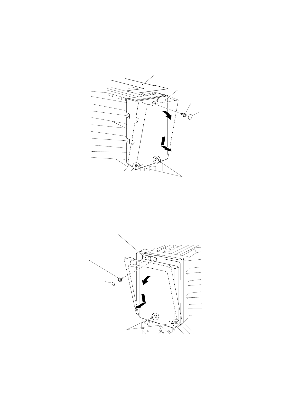
3.1 External Covers
3.1.1 Cover UR (For MX-2001/2003 only)
(1) Remove the two screw cover sheets, then remove the two M3x6 Taptite screws.
(2) Remove the cover UR from the frame UR.
Frame UR
Taptite, M3x6
Screw Cover Sheet
Cover UR
Fig. 3.1
3.1.2 Cover UL (For MX-2001/2003 only)
(1) Remove the two screw cover sheets, then remove the two M3x6 Taptite screws.
(2) Remove the cover UL from the frame UL.
Taptite, M3x6
Screw Cover Sheet
Taptite
M3x6
Screw Cover Sheet
Frame UL
Taptite, M3x6
Screw Cover Sheet
Fig. 3.2
Cover UL
III-3
3.1.3 Cover R
(1) Unstick the upper sheet.
(2) Remove the one screw cover sheet, then remove the one M3x6 Taptite screw.
(3) Incline the cover R outwards using the two hooks as supporting points, then remove
the cover R.
Upper Sheet
Cover R
Taptite, M3x6
Screw Cover Sheet
3.1.4 Cover L
(1) Remove the one screw cover sheet L, then remove the one M3x6 Taptite screw.
(2) Incline the cover L outwards using the two hooks as supporting points, then remove
the cover L.
Taptite, M3x6
Screw Cover Sheet L
hook
Fig. 3.3
Cover L
hook
Fig. 3.4
Note:
When refitting cover L, ensure that the cover is lift fully upwards to reduce the gap on the
upper side of the cover.
III-4

3.1.5 Rear Cover U ASSY (For MX-2001/2003 only)
(1) Release the two hooks to open the rear cover U ASSY.
hook
Rear Cover U ASSY
Fig. 3.5
(2) Release the left hand side of the cover by pulling the hinge of the frame UR outwards,
then remove the cover from the right hand side.
hook
Frame UL
Frame UR
hinge
Rear Cover U ASSY
Fig. 3.6
III-5

(3) Remove the four feed roller springs from the rear cover U by pressing the projection on
the cover .
(4) Remove the pressure roller U from each of the four feed roller springs .
Pressure Roller U
Feed Roller Spring
Feed Roller Spring
Rear Cover U
Fig. 3.7
Note:
When reassembling the pressure roller U into the feed roller spring, note that the axle size on
each side is different as shown in the figure above.
III-6

3.1.6 Rear Cover A ASSY
k
(1) Release the two hooks to open each of the two rear cover A ASSYs.
(2) Release the left hand side of the cover by pulling the hinge of the frame R outwards,
then remove the cover from the right hand side.
hoo
Frame R
hinge
Rear Cover A ASSY
Rear Cover A ASSY
hook
Fig. 3.8
(3) Remove the four feed roller springs in each cover by pressing the projection of the
cover.
(4) Remove the pressure roller from each of the eight feed roller springs .
Pressure Roller
Feed Roller Spring
Feed Roller Spring
Rear Cover A
Fig. 3.9
Note:
When reassembling the pressure roller into the feed roller spring, note that the axle size on
each side is different as shown in the figure above.
III-7

3.1.7 PCB Cover A (MX-2001) / PCB Cover B (MX-2002) /
PCB Cover D (MX-2003 Upper Unit)
(1) Remove the four M3x6 Taptite screws.
(2) Remove the PCB cover A(B/D).
Main frame R
PCB Cover A(B)
Taptite, M3x6
Note:
For the PCB cover C (MX-2003 Lower unit), it is already removed when you remove the
upper unit from the lower unit.
3.1.8 Bin
(1) Remove the paper stopper from the bins.
Bin
Taptite, M3x6
Fig. 3.10
Paper Stopper
Bin
Paper Stopper
Fig. 3.11
III-8

(2) Slide bins #2 and #4 (MX-2001/2003 lower) or #7 and #9 (MX-2002/2003 upper)
(B)
towards you.
Bin #4(9)
Bin #2(7)
Fig. 3.12
(3) For other bins, slightly release the right side of the bin by pulling it toward you, then
incline the bin downward to remove it.
(4) Remove the front sheet A(B).
Bin #5(10)
Bin #3(8)
Bin #1(6)
Front Sheet A
Fig. 3.13
III-9

3.2 Remove the Main Frame Unit from the Under Frame Unit (For MX-2001/2003 only)
(1) Disconnect the harness connector of the solenoid U and the entrance sensor
connector from the I/F PCB A(C) ASSY.
(2) Remove the three M3x6 Taptite screws securing the arm AL and the arm UL. Remove
the three M3x6 Taptite screws securing the arm AR and the arm UR.
(3) Lift up the main frame unit .
Main Frame Unit
I/F PCB A
Taptite, M3x6
Entrance sensor
connector
Solenoid U harness
connector
Taptite, M3x6
Shell Clip
Under Frame Unit
Fig. 3.14
Note:
When reconnecting the entrance sensor connector and the solenoid U harness connector,
ensure the cables are hooked into the shell clip on the right hand side of the feeding motor.
3.3 Main Frame Unit
3.3.1 I/F PCB A ASSY (MX-2001) / I/F PCB B ASSY (MX-2002) /
I/F PCB C ASSY (MX-2003 Lower Unit) / I/F PCB D ASSY (MX-2003 Upper Unit)
(1) Disconnect the feeding motor harness connector.
(2) Remove the four M3x16 Taptite screws from the I/F PCB.
(3) Remove the flat cable from the I/F PCB, then remove the I/F PCB A(B/C/D) ASSY .
Taptite, M3x16
Taptite, M3x16
I/F PCB A(B/C/D) ASSY
Feeding motor
harness connector
Flat Cable
Fig. 3.15
III-10

3.3.2 Feeding Motor ASSY
(1) Remove the ten M3x4 screws from the four solenoids A and one solenoid B.
(2) Remove the M3x6 Taptite screw securing the MX ground wire.
(3) Remove the four M4x12 Taptite screws from the arm AL(BL).
Taptite, M4x12
Screw, M3x4
Screw, M3x4
Taptite, M4x12
Screw, M3x4
Arm AL(BL)
Screw, M3x4
Taptite, M3x6
MX Ground Wire
Taptite, M4x12
Main frame L
Taptite, M4x12
Fig. 3.16
(4) Remove the four spacers and the insulation sheet from the arm AL(BL).
(5) Remove the two M3x4 screws to remove the feeding motor ASSY.
Spacer
Arm AL(BL)
Feeding Motor
ASSY
Spacer
Screw, M3x4
Fig. 3.17
Insulation Sheet
III-11

3.3.3 Main PCB A ASSY (MX-2001, MX-2003 Lower Unit) / Main PCB B ASSY (MX-2002,
MX-2003 Upper Unit)
(1) Remove the four M3x10 Taptite screws from the main PCB A(B).
(2) Disconnect the five solenoid A/B harness connectors and the infrared LED harness
connector from the main PCB.
(3) Disconnect the LED harness connector from the main PCB. (MX-2001/2003 only)
(4) Remove the main PCB A(B) ASSY.
Solenoid A harness
Solenoid B
Solenoid B harness
connector
LED Harness
Connector
Solenoid A
connector
Taptite, M3x10
Fig. 3.18
Taptite, M3x10
Main PCB A(B) ASSY
(5) Remove the five sensor guides and the flat cable from the main PCB A(B).
Sensor Guide
Infrared LED harness
connector
Taptite, M3x10
Main frame L
Sensor Guide
Flat Cable
Sensor Guide
Main PCB A(B) ASSY
Fig. 3.19
III-12

3.3.4 Solenoid A/B & LED PCB ASSY (For MX-2001/2003 only)
(1) Remove the four solenoids A and one solenoid B from the main frame L.
(2) Remove the LED PCB ASSY and the LED harness from the main frame L. (MX-
2001/2003 only)
Solenoid A
Solenoid A
Solenoid B
LED Harness
Fig. 3.20
LED PCB ASSY
Main frame L
Note:
When replacing/reassembling the solenoid A/B ASSY, ensure that you reduce the gap at
the left hand side as shown in the figure below.
When replacing/reassembling the solenoid harnesses, the infrared LED harness and the
LED harness on the main frame L, refer to the figure below;
Harness guide
MX Ground Wire
Infrared LED Harness
For the first batch of products, a
clip is assembled on the main
frame L beside the harness guide.
Be sure to hook the infrared LED
harness and MX ground wire into
both the clip and the harness
guide.
Solenoid A
Solenoid B
LED Harness
Main PCB ASSY
Main frame L
Fig. 3.21
III-13

3.3.5 Sensor PCB ASSY
(1) Remove the one M3x6 Taptite screw securing the MX ground wire.
(2) Remove the four M4x12 Taptite screws to remove the arm AR(BR) from the main
frame R.
Taptite, M4x12
Arm AR(BR)
Taptite, M4x12
Taptite, M3x6
MX Ground Wire
Main frame R
Fig. 3.22
Caution:
After removing the arm AR (BR) from the main frame R, do not place the unit face downward.
Failure to do so will cause damage to the discharging brush holder and this will cause misfeeding of the paper
(3) Remove the two M3x10 Taptite screws to remove the sensor PCB ASSY.
(4) Disconnect the infrared LED harness connector from the sensor PCB.
Taptite, M3x10
Taptite, M3x10
Sensor PCB ASSY
Infrared LED Harness
MX Ground Wire
Fig. 3.23
III-14

Note:
g
g
g
g
j
j
k
When replacing/reassembling the infrared LED harness and MX ground wire, ensure that the
cable length for the main frame R side as follows;
Infrared LED harness: 130 ± 5mm
MX ground wire: 65 ± 5mm
3.3.6 Actuator A/B
(1) Release the hook on the right hand side on the rear cover B to remove it.
Main frame R
hook
Rear Cover B
Main frame L
Fig. 3.24
Main frame R
(2) Remove the five idle gears 34, five swing arms and two gears 24 from the main frame
R.
Idle Gear 34
Swin
arm
Idle Gear 34
Swin
arm
Swin
arm
Main frame R
Swin
arm
Pro
ection mar
Main flap shaft
ection mark
Pro
Fig. 3.25
Note:
When reassembling the swing arm onto the main flap shaft, refer to the figure above.
III-15
Idle Gear 34
Idle Gear 24

(3) Remove the five springs from the main flaps and the main frame L.
Spring 40
Main flap shaft
Spring 40
Spring 40
Main fame L
Fig. 3.26
(4) Release the left side of the five main flaps from the main frame R to remove them.
Main frame R
Main Flap
Main Flaps
Main frame L
Main Flap
Main Flap
Fig. 3.27
III-16

(5) Release the hook of the actuator B, then slightly slide the actuator A to the left hand
side to remove the five actuators B from the main frame L.
(6) Slide the five actuators A leftwards to remove them from the main frame A, B and C.
Actuator A
Main frame L
Feed Roller B
Actuator B
Actuator B
Gear 20
Fig. 3.28
Note:
Before removing the actuator A/B from the main frame
A,
remove the gear 20 from the left
side of the feed roller B. Refer to the figure above.
3.3.7 Eject Roller ASSY & Feed Rollers A/B ASSY
(1) Remove the two ground wires from the main frame R.
(2) Remove the two gears 20 from the right hand side of the feed rollers A/B and the five
gears 20 from the eject rollers.
Gear 20
Ground Wire
Gear 20
Gear 20
Main frame R
Gear 20
Ground Wire
Feed Roller A
Feed Roller B
Fig. 3.29
Gear 20
III-17

(3) Remove the 11 (eleven) M3x10 Taptite screws from the main frame R.
j
j
(4) Release the infrared LED harness from the hook of the main frame R.
(5) Remove the main frame R from the main frames A, B, C, and D.
Main frame R
Infrared LED
Harness
Taptite, M3x10
MX Ground Wire
Main frame A
Main frame B
Main frame L
Main frame C
Main frame B
Main frame D
Fig. 3.30
(6) Remove the feed roller A ASSY and feed roller B ASSY from the main frame L.
(7) Remove the two washers from each feed roller.
(8) Push the hook from the left side of the main frame to remove the five eject roller
ASSYs.
Washer
Taptite, M3x10
Taptite, M3x10
Taptite, M3x10
Taptite, M3x10
Feed Roller A ASSY
Washer
Main frame L
Washer
Feed Roller B
ASSY
Fig. 3.31
Washer
hook
ect Roller
E
E
ect Roller ASSY
III-18

3.3.8 Eject Pinch Roller ASSY & Discharging Brush
,
j
g
(1) Remove the 11 (eleven) M3x10 Taptite screws from the main frame L.
(2) Remove the main frame L from the main frames A, B, C, and D.
(3) Release the MX ground wire and infrared LED harness from the hook on the main
frame L to remove them.
Main frame A
Main frame B
Main frame C
Main frame B
Main frame D
Main frame L
Taptite, M3x10
Taptite
M3x10
Taptite, M3x10
Infrared LED
Harness
MX Ground Wire
Fig. 3.32
(4) Remove the 20 (twenty) eject pinch rollers and the 20 (twenty) pinch springs from the
main frames A, B, and C.
(5) Remove the five discharging brush ASSYs.
Eject Pinch Roller ASSY
ect Pinch Roller
E
Pinch Sprin
Main frame B/C/D
Discharging Brush ASSY
Fig. 3.33
III-19

Note:
When reassembling the main frame A, B, C and D, note that the shape and number of ribs on
each frame are different as shown in the figure below;
Ensure to assemble each frame on to the correct position.
Main Frame A
Main Frame B
Main Frame C
Main Frame D
Fig. 3.34
3.4. Under Frame Unit (For MX-2001/2003 only)
3.4.1 Actuator U
(1) Remove the rib U from the right hand side of the actuator U, then remove the actuator
U from the frame U.
Actuator U
Frame U
Rib U
Fig. 3.35
III-20

3.4.2 Solenoid U
(1) Remove the three M4x12 and one M3x10 Taptite screws from the arm UL.
(2) Remove the two M3x4 screws securing the solenoid U.
(3) Remove the arm UL, then remove the solenoid U from the frame UL.
Screw, M3x4
Taptite, M4x12
Solenoid U
Frame UL
Arm UL
Taptite, M3x10
Fig. 3.36
Note:
When replacing/reassembling the solenoid U ASSY, ensure that you reduce the gap at the
rear side of the frame UL.
3.4.3 Photo Interrupter
(1) Unstick the sheet U and the protect sheet U from the frame U.
(2) Release the hooks from the frame U to remove the photo interrupter.
(3) Disconnect the entrance sensor harness connector from the photo interrupter.
Photo Interrupter
hooks
Entrance Sensor
Harness
Frame U
Frame U
Protect Sheet U
Fig. 3.37
III-21
Sheet U

3.4.4 Feed Roller U ASSY
(1) Remove the four M4x12 Taptite screws to remove the arm UR from the frame UR.
Frame UR
Arm UR
Taptite, M4x12
Fig. 3.38
(2) Remove the eight ribs from the frame U.
Rib U
Feed Roller U ASSY
Fig. 3.39
Taptite, M4x12
Rib U
Frame U
(3) Remove the ground wire U.
(4) Release the hook to remove gear 20 from the feed roller U ASSY.
Frame U
hook
Ground Wire U
Gear 20
Fig. 3.40
III-22

(5) Slightly slide the feed roller U ASSY to the right hand side to release the left side of the
roller, then remove the feed roller.
3.4.5 Flap U
(1) Remove the spring 40 from the release link, then remove the release link.
(2) Remove the spring 35 from the flap U.
Frame U
Frame UL
Feed roller U ASSY
Fig. 3.41
Frame UL
Spring 35
Spring 40
Fig. 3.42
(3) Remove the flap U from the frame UL.
Frame UR
Release link
Flap U
Frame U
Flap U
Frame UL
Fig. 3.43
III-23

3.5 Remove the Upper Unit from the Lower Unit (For MX-2003 only)
When you disassemble the MX-2003 Mailbox unit, you have to remove the upper unit from
the lower unit first. Follow the steps below;
(1) Remove the two screw cover sheets, then remove the two M3x6 Taptite screws from
each of the cover UR and cover UL.
(2) Remove the cover UR and cover UL from the frame.
(3) Remove the two screw cover sheets, then remove the two screws from each of the
cover R and cover L of the lower unit..
(4) Remove the cover R and cover L.
Screw, TORX M3x8
Taptite, M3x6
Cover R
Screw Cover Sheet
Taptite, M3x6
Screw Cover Sheet
Taptite, M3x6
Screw, TORX M3x8
Cover L
Cover UL
Screw Cover Sheet
Taptite, M3x6
Note:
1) One of the two screws securing the cover R/L is very special. (They are indicated RED in
Cover UR
Screw Cover Sheet
Fig. 3.44
the figure above.) When disassembling/re-assembling the screw, you need a special
screw driver. Refer to the figure below and the parts reference list;
Screw, TORX M3x8
TORX screw driver
Fig. 3.45
2) Refer to Section 3.1.3 ‘Cover R’ and 3.1.4 ‘Cover L’ in this chapter for details on removing
the cover R/L from the main frame.
III-24

(5) Remove the four M3x6 Taptite screws, then remove the PCB cover C.
PCB Cover C
Taptite, M3x6
Fig. 3.46
(6) Remove the M3x4 screw securing the lower and upper units on the main frame R.
Upper Unit
Main frame R
Screw, M3x4
Fig. 3.47
III-25

(7) Remove the M3x4 screw securing the lower and upper units on the main frame L.
(8) Unhook the harness from the shell clip, then disconnect the harness connector from
the I/F PCB C.
Upper Unit
Shell Clip
Main frame L
I/F PCB C
Harness connector
Fig. 3.48
Screw, M3x4
Note:
When replacing/re-assembling the harness, refer to the figure below;
Fig. 3.49
III-26

(9) Lift up the upper unit from the lower unit.
Upper Unit
Lower Unit
Fig. 3.50
Disassembling steps for other parts are the same with the MX-2001/2002. See the previous
sections.
III-27

3.6 Packing of MX-2003
r
When unpacking/re-packing the MX-2003 mailbox unit, refer to the figure below;
Lower Pad (R)
Base Plate (R)
Carton Cove
AC Cord
Accessory bag
(Documents)
Accessory Carton
Accessory
Upper Pad (R)
MX-2003
Mailbox unit
AC Adapter
Base Plate (L)
Lower Pad (L)
Upper Pad (L)
Carton Pad
Carton
Fig. 3.51
III-28

4. APPLICATION OF GREASE
j
When replacing/reassembling the following parts, remove the old grease and apply a suitable
amount of grease referring to each figure.
4.1 Rollers
4.1.1 Feed Roller A/B ASSY
Apply 1 rice-grain size
KANTO KASEI FLOIL GE-676 to the points (
Main Frame L
4.1.2 Eject Roller ASSY
of grease, SHINETSU SILICON KS-64F to the points (
Feed Roller A ASSY
Feed Roller B ASSY
Ground Wire
Fig. 3. 52
), as shown below;
~
Main Frame R
Arm AR
Arm AR
) and
~
Apply 1 rice-grain size
shown below;
Main Frame L
of grease, SHINETSU SILICON KS-64F to the points (
Main Frame R
ect Roller ASSY
E
Fig. 3. 53
) as
~
III-29

Apply 1 sesame-grain size
(U)
)
shown below;
4.1.3 Feed Roller U ASSY
of grease, SHINETSU SILICON KS-64F to the points (
Main Frame A ~ D
Eject Roller ASSY
Fig. 3. 54
)
as
Apply 1 rice-grain size
KANTO KASEI FLOIL GE-676 to the points (
Apply 1 sesame-grain size
shown below;
of grease, SHINETSU SILICON KS-64F to the points (
of grease, SHINETSU SILICON KS-64F to the points (
Frame UR
Frame UL
Feed Roller U
ASSY
Fig. 3. 55
), as shown below;
~
Rib U (8 pcs
Ground Wire U
Arm UR
), and
~
)
as
4.1.4 Pressure Roller / Pressure Roller U
Apply 1 sesame-grain size
as shown below;
of grease, SHINETSU SILICON KS-64F to the points (
Feed Roller Spring
Pressure Roller
Fig. 3. 56
III-30
~
)

4.2 Gears
g
4.2.1 Gears on the Main Frame R
PR99011
Apply 1 rice-grain size
shown below;
Gear 16
of grease, SHINETSU SILICON KS-64F to the points (
Feed Roller Gear
c
Idle Gear 34
h
d
i
Gear 24
e
j
f
k
c ~
l
) as
Main Frame R
g
4.2.2 Gears on the Main Frame L
Apply 1 rice-grain size
shown below;
Feedin
Motor
of grease, SHINETSU SILICON KS-64F to the points (
c
Fig. 3.57
d
Gear 16/40
l
Arm AL
Feed Roller Gear
c
~
d
) as
Fig. 3. 58
III-31

4.2.3 Gears on the Frame UR
g
)
PR99011
Apply 1 rice-grain size
shown below;
Frame UR
of grease, SHINETSU SILICON KS-64F to the points (
Idle Gear 34
c
Feed Roller Gear
Frame UR
Idle Gear 34
Fig. 3. 59
d
c
~
d
) as
4.3 Others
Apply 1 rice-grain size
shown below;
Gear 16
c
Idle Gear 34
g
of grease, SHINETSU SILICON KS-64F to the points (
d
Main Frame R
Main Flap
f
e
Swing arm
Gear 24
h
arm
Swin
Fig. 3. 60
ij
~
c
j
Main Frame R
) as
Main Frame R
(Frame UR)
Solenoid A/B (U
Main Frame L
(Frame UL)
Main Flap (Flap U)
Fig. 3. 61
III-32

CHAPTER IV TROUBLESHOOTING
1. INITIAL CHECK
(1) Operating environment
Check if :
¸ The source voltage stays within ±10% of the rated voltage shown on the rating
plate.
¸ The room temperature is maintained between 10°C and 32.5°C. The relative
humidity is maintained between 20% and 80%.
¸ There is enough space around the unit so that the following operations are
possible.
a) The power cord and modular jack connector can be connected
b) The rear cover can be opened to remove jammed paper.
c) Various maintenance work can be easily implemented.
¸ The unit is installed on a solid, level surface.
¸ The unit is not exposed to direct sunlight.
¸ The unit is not located in a dusty place.
¸ The room is well-ventilated.
¸ The unit is not placed where the ventilation hole of the unit is blocked.
¸ The unit is not exposed to ammonia fumes or other harmful gases.
¸ The unit is not located in a hot or humid area (such as near water or a
humidifier).
(2) Print paper
Check if :
¸ A recommended type of print paper is being used. [If the paper is too thick or too
thin, or tends to curl, paper jams or paper feed problems may occur, or printed
images may be blurred.]
¸ The print paper is damped. [If so, use fresh paper, and check whether the print
quality improves or not.]
¸ The print paper is short-grained paper or acid paper. [If so, print quality
problems may occur. For further information, refer to paper specifications in
Chapter II.]
(3) Others
Condensation:
¸ When the unit is moved from a cold room into a warm room in cold weather,
condensation may occur inside the unit.
¸ Condensation on the hopper gate and separation pad may cause paper feed
problems.
If condensation has occurred, wipe the effected parts with a dry cloth and leave the
printer for 2 hours to allow it to reach room temperature.
IV-1

2. MTBF / MTTR
The meantime between failure (MTBF) and the meantime to repair (MTTR) for this printer
are as follows;
MTBF: 4,000 hours
MTTR: Less than 30 minutes
IV-2

3. TROUBLESHOOTING
Problem Cause Check Result Remedy
The paper is not ejected to the
Mailbox unit even though paper
output is set to the Mailbox unit in
the printer driver.
The ‘STACK PAPER JAM’
message appears when the printer
is turned on even though no paper
is ejected to the Mailbox unit.
The ‘STACK FULL’ message
appears even though no paper is
ejected to the Mailbox unit.
Installation error Is the modular cable connected correctly? No Turn off the printer power switch and
unplug the AC adapter cord of the Mailbox
unit from the outlet. Connect the modular
cable correctly, then plug in the AC
adapter cord and turn on the printer power
switch again.
Modular cable Is the timing of pins 2 and 4 of the P6
connector on the I/F PCB normal?
(Refer to the figure on page II-6 of
Chapter II.)
I/F PCB Is a voltage of +5V supplied to pin 16 of
the P1 connector on the I/F PCB?
I/F PCB
Main PCB
Installation error Is the AC adapter cord connected
Adapter
I/F PCB
Sensor PCB
Main PCB
Is the timing of pins 5 and 6 of the P1
connector on the I/F PCB normal?
(Refer to the figure on page II-6 of
Chapter II.)
correctly?
Is the AC adapter jack connected to the
Mailbox unit correctly?
Is a voltage of +5V supplied to pin 1 of the
P5 connector on the I/F PCB?
Does the error message appears for all
bins?
No Replace the modular cable.
No. Replace the I/F PCB.
No Replace the I/F PCB.
Yes Replace the main PCB.
No Turn off the printer power switch and
connect the AC adapter cord or the AC
adapter jack of the Mailbox unit correctly.
Then, plug in the AC adapter cord and
turn on the printer power switch again.
No Replace the adapter.
Yes Replace the I/F PCB.
Yes Replace the sensor PCB.
No Replace the main PCB.
IV-3

Problem Cause Check Result Remedy
The paper is ejected to the printer
output tray and the ‘STACK PAPER
JAM’ message appears, even
though paper output is set to the
Mailbox unit.
The ‘STACK PAPER JAM’
message appears even though the
paper is ejected to the Mailbox unit
correctly.
The paper is not ejected to the
specified bin but fed into the back of
the unit.
The ‘STACK PAPER JAM’
message also appears.
Flap U Does the flap U work correctly? No Apply the grease to the specified points of
the flap U.
For details, refer to Section 4 of Chapter
3.
Solenoid U
Main PCB
Actuator U Does the actuator U work correctly? No Check if there is any flash on the frame U
Main PCB
Photo interrupter
Feeding motor Does the feeding motor rotate? No Replace the feeding motor and the I/F
Main flap of
each bin
Solenoid A/B
Main PCB
Is a voltage of +24V supplied to pin 1 and
a voltage of app. 1V supplied to pin 2 of
the P2 connector on the I/F PCB when the
flap U operates?
Is the timing of pin 3 of the connector P3
on the I/F PCB normal when the actuator
U operates?
(Refer to the figure on page II-6 of
Chapter II.)
Does the main flap of each bin work
correctly?
Is a voltage of +24V supplied to pin 1 and
a voltage of app. 1V supplied to pin 2 of
the connector on the main PCB when
each flap operates?
<Connector No. for each bin>
#1 Bin: P7 #2 Bin: P6
#3 Bin: P5 #4 Bin: P3
#5 Bin: P2
Yes Replace the solenoid U.
No Replace the main PCB.
or actuator U.
If there is no flash, replace the actuator U.
Yes Replace the main PCB.
No Replace the photo interrupter.
PCB.
No Apply the grease to the specified point on
the main flap of each bin. For details,
refer to Section 4 of Chapter III.
Yes Replace the solenoid A/B.
No Replace the main PCB.
IV-4

Problem Cause Check Result Remedy
The ‘STACK PAPER JAM’
message appears when 100mm of
paper is ejected to the Mailbox unit.
Note:
‘Main PCB’ described in the above table is indicating ‘Main PCB A’ for MX-2001 or MX-2003 lower unit and ‘Main PCB B’ for MX-2002 or MX2003 upper unit.
‘I/F PCB’ described in the above table is indicating ‘I/F PCB A’ for MX-2001, ‘I/F PCB B’ for MX-2002, ‘I/F PCB C’ for MX-2003 lower unit and ‘I/F
PCB D’ for MX-2003 upper unit.
Harness wiring Does the infrared LED harness interfere
with the actuator A/B?
Actuator A/B of
each bin
Main PCB Yes Replace the main PCB.
Does the actuator A/B of each bin work
correctly?
Yes Re-wire the infrared LED harness not to
interfere with the actuator A/B.
No Replace the actuator A/B of each bin.
IV-5

Appendix 1. Main PCB Circuit Diagram, (1/2)
CODE UK4287-000
NAME
A - 1
B512015CIR

Appendix 2. Main PCB Circuit Diagram, (2/2)
CODE UK4287-000
NAME
A - 2
B512015CIR

Appendix 3. I/F PCB Circuit Diagram
CODE UK4292-000
NAME
B512017CIR
A - 3

INDEX
A
actuator A........................................II-7, III-17
actuator B........................................II-7, III-17
actuator U........................................II-7, III-20
feeding motor drive circuit......................... II-5
feeding speed ............................................ I-3
flap U..............................II-7, II-8, III-23, III-32
flat cable................................................. III-12
front sheet A............................................. III-9
front sheet B............................................. III-9
B
big stacker mode........................................I-3
bin............................................... I-2, II-7, III-9
bin capacity.................................................I-3
bin capacity sensor....................................II-4
bin solenoid drive circuit............................II-3
C
communication ..........................................II-5
condensation........................................... IV-1
cover L......................................................III-4
cover R.....................................................III-4
cover UL...................................................III-3
cover UR...................................................III-3
CPU...........................................................II-3
D
DC jack connector......................................I-2
dimensions .................................................I-3
discharging brush...................................III-19
G
gear........................................................ III-31
general block diagram............................... II-1
grease.................................................... III-29
I
I/F PCB ..................................................... II-4
block diagram........................................ II-4
circuit diagram.......................................A-3
I/F PCB A............................................... III-10
I/F PCB B............................................... III-10
I/F PCB C..................................... III-10, III-26
I/F PCB D............................................... III-10
infrared LED drive circuit .......................... II-4
infrared LED harness............................. III-14
insulation sheet...................................... III-11
L
LED harness.......................................... III-13
LED PCB................................................ III-13
E
eject pinch roller .....................................III-19
eject roller............................. II-7, III-18, III-29
entrance flap..............................................II-8
entrance sensor.........................................II-5
entrance sensor harness........................III-21
entrance solenoid......................................II-8
entrance solenoid drive circuit...................II-3
environment............................................. IV-1
F
feed roller A.......................... II-7, III-18, III-29
feed roller B.......................... II-7, III-18, III-29
feed roller U.......................... II-7, III-23, III-30
feeding motor...................................II-8, III-11
M
mailbox....................................................... I-1
main flap ........................II-7, II-9, III-16, III-32
main PCB.................................................. II-3
block diagram........................................ II-3
circuit diagram....................................A-1-2
main PCB A ........................................... III-12
main PCB B ........................................... III-12
mini DIN connector .................................... I-2
modular jack............................................... I-2
MTBF.......................................................IV-2
MTTR.......................................................IV-2
MX ground wire...................................... III-11
i

P
W
packing...................................................III-28
paper.................................................I-4, IV-1
paper size...............................................I-4
paper type...............................................I-4
feedable thickness..................................I-4
feedable weight.......................................I-4
recommended paper...............................I-4
paper stopper.............................I-2, II-7, III-8
PCB cover A.............................................III-8
PCB cover B.............................................III-8
PCB Cover C..........................................III-25
PCB Cover D............................................III-8
photo interrupter.....................................III-21
power consumption....................................I-3
power supply LED drive circuit..................II-4
power supply LED PCB.............................II-5
precaution.................................................III-1
pressure roller.................................III-7, III-30
pressure roller U.............................III-6, III-30
printer output tray.......................................I-2
pinch spring............................................III-19
protect sheet U.......................................III-21
weight.........................................................I-3
R
regulator....................................................II-4
rear cover A..............................................III-7
rear cover U..............................................III-5
S
sensor guide...........................................III-12
sensor PCB.....................................II-5, III-14
serial interface circuit.................................II-5
sheet U...................................................III-21
solenoid A........................................II-9, III-13
solenoid B...............................................III-13
solenoid U........................................II-8, III-21
sorter..........................................................I-1
spacer.....................................................III-11
stacker........................................................I-1
T
torque values............................................III-1
U
upper sheet...............................................III-4
ii

R
MAILBOX UNIT
FOR LASER PRINTER
PARTS REFERENCE LIST
MODEL:MX-2001/MX-2002/MX-2003
Note:
While the MX-2001 Mailbox unit is available in all countries, the
MX-2003 is available in U.S. and Canada only, and the MX-2002
is available in the other countries than U.S. and Canada.
Oct., '98
54T051NE0

NOTE FOR USING THIS PARTS REFERENCE LIST
REF.NO.
CODE
Q’TY
DESCRIPTION
SYMBOL
REMARK
(1)
(4)
(3)
(2)
Circuit board No.
(The first version has no sign.)
1. In the case of ordering parts, it needs mentioning the following items:
(1) Code
(2) Q'ty
(3) Description
(4) Symbol ( PCB No., Revision , and Parts location mounted on the PCB.)
Note : No orders without Parts Code or Tool No. can be accepted.
< Example >
Revision No.: marked on the main printed circuit board.
B48K056 - 201A
Design change indication
Specification No .
Pattern alteration No.
Revision No.: marked on the power supply printed circuit board.
Rev. A
Design change indication
2. Design-changed parts :
If the parts are changed, any one of the following symbols is indicated in the REMARKS
column.
#A : compatible between old and new
#B : replaceable from old to new
#D : incompatible
# : newly established
3. The original of this list was made based on the information available in October, 1998.
4. Parts are subject to change in design without prior notice.

CONTENTS
1. UNDER FRAME UNIT...........................................................................1
2. UNDER UNIT COVERS ........................................................................1
3. MAIN FRAME UNIT...............................................................................3
4. COVERS ...............................................................................................5
5. PCBS.....................................................................................................5
6. PCB RELATED......................................................................................7
7. POWER SUPPLY..................................................................................7
8. AC CORD..............................................................................................9
9. ACCESSORIES.....................................................................................9
10. PACKING MATERIALS (MX-2001/2002) ............................................11
11. PACKING MATERIALS (MX-2003) .....................................................11
12. ADJUSTING TOOL KIT.......................................................................13

1. UNDER FRAME UNIT
PR98306
REF.NO.
CODE
Q'TY
DESCRIPTION
REMARK
1
UK4325000
1
PHOTO INTERRUPTER:1241
2
UK4314001
1
ENTRANCE SENSOR HARNESS 3P
3
UH3904001
1
SHEET U
4
UH3990001
1
PROTECT SHEET U
5
UH3907001
1
ACTUATOR U
6
UH3908001
1
FEED ROLLER U ASSY
7
UH3912001
1
GROUND WIRE U
8
UH3913001
1
FLAP U
9
UH3915001
1
SPRING 35
10
UH3916001
1
SPRING 40
11
UH3917001
1
SOLENOID U
12
060300416
2
SCREW, BIND M3X4
13
087411216
3
TAPTITE, CUP B M4X12
14
087311016
1
TAPTITE, CUP B M3X10
15
087411216
4
TAPTITE, CUP B M4X12
16
087320616
4
TAPTITE, CUP S M3X6
MODEL MX-2001/2003 54T-X20/X40-500
2. UNDER UNIT COVERS
REF.NO.
CODE
Q'TY
DESCRIPTION
REMARK
1
UH3930001
1
COVER UL
2
UH3931001
1
COVER UR
3
087320616
4
TAPTITE, CUP S M3X6
4
UH3932001
4
SCREW COVER SHEET
5
UH3933001
1
REAR COVER U ASSY
5-1
UH3935001
4
FEED ROLLER SPRING
5-2
UH3936001
4
PRESSURE ROLLER U
MODEL MX-2001/2003 54T-X20/X40-510
- 1 -

1. UNDER FRAME UNIT
16
13
12
14
16
8
6
15
7
5
1
15
2
11
9
3
4
10
2. UNDER UNIT COVERS
1
MODEL MX-2001/2003 54T-X20/X40-500
5
5-1
5-2
4
3
2
3
4
MODEL MX-2001/2003 54T-X20/X40-510
- 2 -

3. MAIN FRAME UNIT
REF.NO. CODE Q'TY DESCRIPTION REMARK
1 UK4298001 1INFRARED LED HARNESS 2P
2 UK4319001 1MX GROUND WIRE
3 UH3939001 5DISCHARGING BRUSH ASSY
4 UH3323001 20EJECT PINCH ROLLER ASSY
5 UH3948001 20PINCH SPRING
6 087311016 22TAPTITE, CUP B M3X10
7 UH3951001 5EJECT ROLLER ASSY
8 UH3953001 5ACTUATOR A
9 UH3954001 5ACTUATOR B
10 UH3955001 1FEED ROLLER A ASSY
11 UH3957001 1FEED ROLLER B ASSY
12 048040346 4WASHER E4
13 UH3959001 5MAIN FLAP
14 UH3916001 5SPRING 40
15 UH3962001 2GROUND WIRE
16 087411216 4TAPTITE, CUP B M4X12
17 UH3964001 4SOLENOID A
18 UH3965001 1SOLENOID B
19 UH3970001 4SPACER
20 UH3971001 1INSULATION SHEET
21 UH1565001 1FEEDING MOTOR ASSY
22 060300416 2SCREW, BIND M3X4
23 087411216 4TAPTITE, CUP B M4X12
24 060300416 10SCREW, BIND M3X4
25 UH4001001 1SHELL CLIP
26 060300416 2
SCREW, BIND M3X4 (MX-2003 LOWER,
FOR CONNECTION WITH UPPER UNIT)
MODEL MX-2001/2002/2003 54T-X20/X30-600, 54T-X40-600/601
T/I NO. PR98267 / PR98306
- 3 -

3. MAIN FRAME UNIT
12
12
17
17
12
10
11
12
13
15
7
1
6
13
7
6
6
8
6
8
5
14
6
4
5
5
4
9
6
14
5
4
14
6
9
2
16
5
4
4
5
4
5
5
5
6
9
26
18
24
23
19
24
23
24
21
24
19
25
MODEL MX-2001/2002/2003 54T-X20/X30-600, 54T-X40-600/601
T/I NO. PR98267 / PR98306
26
23
22
20
3
16
3
16
- 4 -

4. COVERS
REF.NO. CODE Q'TY DESCRIPTION REMARK
1 UH4018001 5BIN
2 UH3974001 2REAR COVER A ASSY
2-1 UH3935001 8FEED ROLLER SPRING
2-2 UH2360000 8PRESSURE ROLLER
3 UH3977001 1COVER L
4 UH3978001 1COVER R
5 087320616 2TAPTITE, CUP S M3X6
6 UH3932001 1SCREW COVER SHEET
7 UH3993001 1SCREW COVER SHEET L
8 UH3979001 1UPPER SHEET (MX-2001/2003 UPPER)
9 UH3981001 1FRONT SHEET A (MX-2001/2003 LOWER)
9 UH3987001 1FRONT SHEET B (MX-2002/2003 UPPER)
10 UH3989001 1PAPER STOPPER
11 UH4019001 2
SCREW, BIND(TORX) M3X8 (MX-2003 LOWER)
12 UH3993001 2SCREW COVER SHEET L (MX-2003)
MODEL MX-2001/2002/2003 54T-X20/X30-610, 54T-X40-610/611
T/I NO. PR98306 / PR98307
5. PCBS
REF.NO. CODE Q'TY DESCRIPTION SYMBOL REMARK
1 UK4283001 1MAIN PCB ASSY A (MX-2001/2003 LOWER)B512015-200D
1 UK4284001 1MAIN PCB ASSY B (MX-2002/2003 UPPER)B512015-201D
2 UH3901001 5SENSOR GUIDE
3 087311016 4TAPTITE, CUP B M3X10
4 UK4288001 1I/F PCB ASSY A (MX-2001) B512017-200B
4 UK4289001 1I/F PCB ASSY B (MX-2002) B512017-201B
4 UK4382001 1I/F PCB ASSY C (MX-2003 LOWER) B512017-202
4 UK4383001 1I/F PCB ASSY D (MX-2003 UPPER) B512017-203
5 087321616 4TAPTITE, CUP S M3X16
6 UK4293001 1SENSOR PCB ASSY B512016
7 087311016 2TAPTITE, CUP B M3X10
8 UK4317001 1LED PCB ASSY (MX-2001/2003 LOWER) B512036
MODEL MX-2001/2002/2003 54T-X20/X30-100, 54T-X40-100/101
T/I NO. PR98306, PR99026
- 5 -

4. COVERS
12
11
2-2
2-2
T/I NO. PR98306
5. PCBS
12
2-1
2
8
2-1
11
5
7
3
MODEL MX-2001/2002/2003 54T-X20/X30-610, 54T-X40-610/611
9
6
5
4
1
10
2
3
4
8
7
3
2
5
6
5
1
7
5
3
MODEL MX-2001/2002/2003 54T-X20/X30-100, 54T-X40-100/101
- 6 -

6. PCB RELATED
REF.NO. CODE Q'TY DESCRIPTION REMARK
1 UK4297000 1FLAT CABLE
2 UK4299001 1LED HARNESS 2P (MX-2001/2003 LOWER)
3 087320616 2TAPTITE, CUP S M3X6
4 UH3992001 1PCB COVER A (MX-2001)
4 UH3982001 1PCB COVER B (MX-2002)
4 UH4016001 1PCB COVER C (MX-2003 LOWER)
4 UH4017001 1PCB COVER D (MX-2003 UPPER)
5 087320616 4TAPTITE, CUP S M3X6
MODEL MX-2001/2002/2003 54T-X20/X30-110, 54T-X40-110/111
T/I NO. PR98306
7. POWER SUPPLY
REF.NO. CODE Q'TY DESCRIPTION REMARK
1 UK4300001 1MX AC ADAPTER
MODEL MX-2001/2003 54T-X20/X40-200
- 7 -

8. AC CORD
1A
1B
1C
1D
9. ACCESSORIES
MODEL MX-2001/2003 54T-X20/X40-230
2
5
1
3
T/I NO. PR99196
4
MODEL MX-2001/2002/2003 54T-X20/X30/X40-920
- 10 -

8. AC CORD
REF.NO.
CODE
Q'TY
DESCRIPTION
REMARK
1A
UK4302001
1
AC CORD, SAA
1B
UK4303001
1
AC CORD, BS
1C
UK4301001
1
AC CORD, EUR
1D
UK4332001
1
AC CORD UL/CSA ASSY
MODEL MX-2001/2003 54T-X20/X40-230
T/I NO. PR99191
9. ACCESSORIES
REF.NO.
CODE
Q'TY
DESCRIPTION
REMARK
1
UH3995001
1
USER'S GUIDE, EUR
1
UH3747001
1
USER'S GUIDE, US/CAN
2UK4305001
1
MODULAR CORD 8P (MX-2001/2003)
3
060300814
2
SCREW, BIND M3X8 (MX-2002)
4
UE0331001
1
BAG, 215X350H
5
UK4306001
1
MINI DIN CORD 8P (MX-2002)
MODEL MX-2001/2002/2003 54T-X20/X30/X40-920
T/I NO. PR98306, PR99196
- 9 -

8. AC CORD
1A
1B
1C
1D
9. ACCESSORIES
MODEL MX-2001/2003 54T-X20/X40-230
2
1
3
4
MODEL MX-2001/2002/2003 54T-X20/X30/X40-920
- 10 -

10. PACKING MATERIALS (MX-2001/2002)
REF.NO. CODE Q'TY DESCRIPTION REMARK
1 UE0782001 1CARTON, MX-2001
1 UE0783001 1CARTON, MX-2002
2 UE0784001 1STYROFOAM PAD (R), MX-2001
2 UE0786001 1STYROFOAM PAD (R), MX-2002
3 UE0785001 1STYROFOAM PAD (L), MX-2001
3 UE0787001 1STYROFOAM PAD (L), MX-2002
4 UE0790001 1CARTON, ACCESSORIES
5 UE0798001 2BASE PLATE R, MX-2001
5 UE0800001 2BASE PLATE R, MX-2002
6 UE0799001 2BASE PLATE L, MX-2001
6 UE0801001 2BASE PLATE L, MX-2002
7 UE0696001 1BAG, 700X800H (BODY)
8 UE0823001 1STYROFOAM PAD (F)
MODEL MX-2001/2002 54T-X20/X30-930
T/I NO. PR98268 / PR99039
11. PACKING MATERIALS (MX-2003)
REF.NO. CODE Q'TY DESCRIPTION REMARK
1 UE0809001 1CARTON, MX-2003
2 UE0810001 1CARTON PAD, MX-2003
3 UE0811001 1STYROFOAM PAD LOWER (R), MX-2003
4 UE0812001 1STYROFOAM PAD LOWER (L), MX-2003
5 UE0813001 1STYROFOAM PAD UPPER (R), MX-2003
6 UE0814001 1STYROFOAM PAD UPPER (L), MX-2003
7 UE0790001 1CARTON, ACCESSORIES
8 UE0798001 2BASE PLATE R, MX-2001
9 UE0799001 2BASE PLATE L, MX-2001
10 UE0816001 1BAG, 800X1100H (BODY)
T/I NO. PR98306 / PR99039
MODEL MX-2003 54T-X40-930
- 11 -

10. PACKING MATERIALS (MX-2001/2002)
4
7
8
2
5
1
3
MODEL MX-2001/2002 54T-X20/X30-930
T/I NO. PR98268 / PR99039
11. PACKING MATERIALS (MX-2003)
7
3
5
6
2
8
9
10
T/I NO. PR98306 / PR99039
6
MODEL MX-2003 54T-X40-930
- 12 -
4
1

12. ADJUSTING TOOL KIT
PRT-402
TOOL NO. TOOL NAME REMARK
PRT-402 TORX SCREW DRIVER, MX-2003
MODEL MX-2003 54T-X40
T/I NO. PR98306
ADD
- 13 -
 Loading...