

Page 1

Page 2

SERVICE MANUAL
MODEL: MP-21C / 21CDX
Page 3

© Copyright Brother 1999
All rights reserved.
No part of this publication may be reproduced in any form or by any means without permission in
writing from the publisher.
Specifications are subject to change without notice.
Trademarks:
The brother logo is a registered trademark of Brother Industries, Ltd.
Microsoft is a registered trademark of Microsoft Corporation.
Windows is a registered trademark of Microsoft Corporation in the U.S. and other countries.
Page 4

TABLE OF CONTENTS
CHAPTER I FEATURES AND SPECIFICATIONS
1. SYSTEM REQUIREMENT---------------------------------------------------I-1
2. FEATURES ----------------------------------------------------------------------I-1
3. CONFIGURATION-------------------------------------------------------------I-3
3.1 Mechanics------------------------------------------------------------------------------------I-3
3.2 Electronics -----------------------------------------------------------------------------------I-4
4. SPECIFICATIONS------------------------------------------------------------- I-5
4.1 Printing----------------------------------------------------------------------------------------I-5
4.2 Functions-------------------------------------------------------------------------------------I-5
4.3 Electrical and Mechanical ----------------------------------------------------------------I-6
4.4 Environment ---------------------------------------------------------------------------------I-6
4.5 Dimensions and Weight ------------------------------------------------------------------I-6
4.6 Recommended Paper --------------------------------------------------------------------I-6
4.7 Paper Specifications ----------------------------------------------------------------------I-7
4.8 Printable Area ------------------------------------------------------------------------------I-8
4.9 Control Panel (LED and Buttons) ---------------------------------------------------- I-10
4.10 How To Clean the Print Head - Purge -------------------------------------------- I-14
4.11 Replacing The Ink Cartridges ------------------------------------------------------- I-15
4.12 Recovery Function - Purge----------------------------------------------------------- I-16
5. SAFETY INFORMATION -------------------------------------------------- I-19
5.1 Ink Safety ---------------------------------------------------------------------------------- I-19
6. CONSUMABLES AND SERVICE ACCESSORIES ---------------- I-19
6.1 Brother Special Paper ------------------------------------------------------------------ I-19
6.2 Ink Cartridges ----------------------------------------------------------------------------- I-19
6.3 ACSF and Parallel I/F Cable ---------------------------------------------------------- I-20
CHAPTER II THEORY OF OPERATION
1. GENERAL----------------------------------------------------------------------- II-1
1.1 Normal Interlace Processing (360dpi) ----------------------------------------------- II-1
1.2 Super Fine Interlace Processing (720dpi) ------------------------------------------II-2
2. ELECTRONICS---------------------------------------------------------------- II-3
2.1 General Block Diagram (MP-21C/MP-21CDX) ------------------------------------ II-3
2.2 Electric Cofiguration ---------------------------------------------------------------------- II-4
2.3 Main PCB -----------------------------------------------------------------------------------II-5
2.4 Head PCB ---------------------------------------------------------------------------------- II-9
2.5 Carriage PCB ------------------------------------------------------------------------------II-9
2.6 Carriage Sensor PCB -------------------------------------------------------------------- II-9
2.7 Power Supply ---------------------------------------------------------------------------- II-10
Page 5

3. MECHANICS -----------------------------------------------------------------II-11
3.1 Overview of Printing Mechanism ---------------------------------------------------- II-11
3.2 Print Head -------------------------------------------------------------------------------- II-12
3.3 Ink Cartridge ----------------------------------------------------------------------------- II-14
3.4 Head Maintenance Mechanism ----------------------------------------------------- II-15
3.5 Sensors ----------------------------------------------------------------------------------- II-16
3.6 Carriage Drive Mechanism ----------------------------------------------------------- II-20
3.7 Paper Feed Mechanism --------------------------------------------------------------- II-21
CHAPTER III DISASSEMBLY AND REASSEMBLY
1. PRECAUTIONS -------------------------------------------------------------- III-1
1.1 Safe Precautions ------------------------------------------------------------------------ III-1
1.2 Attention ----------------------------------------------------------------------------------- III-1
2. TIGHTENING TORQUE LIST--------------------------------------------- III-2
3. DISASSEMBLY ORDER FLOW ----------------------------------------- III-3
PR99052
4. DISASSEMBLING AND REASSEMBLING PROCEDURE ------- III-4
4.1 Ink Cartridge, ACSF --------------------------------------------------------------------- III-4
4.2 Top Cover, Paper Guide, Front Cover, Release Plate, Rear Cover --------- III-5
4.3 Head PCB ASSY ------------------------------------------------------------------------ III-8
4.4 Ink Head Base Unit, Print Head------------------------------------------------------- III-9
4.5 Bottom Cover ----------------------------------------------------------------------------III-12
4.6 Main PCB, Power Supply PCB ASSY ---------------------------------------------III-14
4.7 Paper Feed Motor ASSY -------------------------------------------------------------III-16
4.8 Purge Unit ASSY -----------------------------------------------------------------------III-18
4.9 Paper Feed Frame ASSY ------------------------------------------------------------III-22
4.10 ACSF ------------------------------------------------------------------------------------III-34
5. LUBRICATION---------------------------------------------------------------III-38
6. CLEANING THE PRINTER ----------------------------------------------III-43
6.1 Cleaning The Platen Cover -----------------------------------------------------------III-43
6.2 Cleaning The Edge Of The Head Cap ---------------------------------------------III-43
6.3 Cleaning The Pick-up Roller On The ACSF --------------------------------------III-44
7. PACKING ---------------------------------------------------------------------III-45
Page 6

CHAPTER IV TROUBLESHOOTING
1. INTRODUCTION-------------------------------------------------------------IV-1
1.1 Initial Check -------------------------------------------------------------------------------IV-1
1.2 Basic Procedure -------------------------------------------------------------------------IV-2
2. TROUBLESHOOTING -----------------------------------------------------IV-3
2.1 Troubleshooting Procedure ------------------------------------------------------ IV-3
3. INSPECTION MODE ----------------------------------------------------- IV-10
3.1 Extended Functions ------------------------------------------------------------------- IV-10
3.2 Hidden Functions ---------------------------------------------------------------------- IV-11
3.3 Error Codes ----------------------------------------------------------------------------- IV-13
APPENDIX A
Appendix A1 Head PCB Circuit Diagram ------------------------------------------------A-1
Appendix A2 Main PCB Circuit Diagram (1/3) ------------------------------------------A-2
Appendix A3 Main PCB Circuit Diagram (2/3) ------------------------------------------A-3
Appendix A4 Main PCB Circuit Diagram (3/3) ------------------------------------------A-4
Appendix A5 Cartridge Sensor Circuit Diagram ----------------------------------------A-5
PR99065
APPENDIX B
Appendix B Head Cleaning -----------------------------------------------------------------B-1
Page 7

Chapter I
FEATURES AND
SPECIFICATIONS
Page 8

CONTENTS
1. SYSTEM REQUIREMENTS------------------------------------------------I-1
2. FEATURES----------------------------------------------------------------------I-1
3. CONFIGURATION ------------------------------------------------------------ I-3
3.1 Mechanics------------------------------------------------------------------------------------I-3
3.2 Electronics -----------------------------------------------------------------------------------I-4
4. SPECIFICATIONS ------------------------------------------------------------ I-5
4.1 Printing----------------------------------------------------------------------------------------I-5
4.2 Functions-------------------------------------------------------------------------------------I-5
4.3 Electrical and Mechanical ----------------------------------------------------------------I-6
4.4 Environment ---------------------------------------------------------------------------------I-6
4.5 Dimensions and Weight ------------------------------------------------------------------I-6
4.6 Recommended Paper --------------------------------------------------------------------I-6
4.7 Paper Specifications ----------------------------------------------------------------------I-7
4.8 Printable Area ------------------------------------------------------------------------------I-8
4.9 Control Panel (LED and Buttons) ---------------------------------------------------- I-10
4.9.1 Power LED --------------------------------------------------------------------------- I-10
4.9.2 Alarm LED ---------------------------------------------------------------------------- I-10
4.9.3 Ink LEDs (BC LED and MY LED) ----------------------------------------------- I-11
4.9.4
4.9.5 Clean Button ------------------------------------------------------------------------- I-11
4.9.6 Printer Status ------------------------------------------------------------------------ I-12
4.9.7 Control Panel ------------------------------------------------------------------------ I-12
4.9.8 LEDs ----------------------------------------------------------------------------------- I-13
4.9.9 Printer Status ------------------------------------------------------------------------ I-14
4.10 How to clean the Print Head - Purge ---------------------------------------------- I-14
4.11 Replacing the Ink Cartridges -------------------------------------------------------- I-15
4.12 Recovery Function - Purge ---------------------------------------------------------- I-16
4.12.1 Definition of Terms --------------------------------------------------------------- I-16
4.12.2 Automatic Purge ------------------------------------------------------------------ I-17
4.12.3 Manual Purge ---------------------------------------------------------------------- I-17
4.12.4 Automatic Purge Frequency ---------------------------------------------------- I-17
4.12.5 Purge Sequence ------------------------------------------------------------------ I-18
(On/Off) / Retry Button --------------------------------------------------------- I-11
PR99052
5. SAFETY INFORMATION ------------------------------------------------- I-19
5.1 Ink Safety ---------------------------------------------------------------------------------- I-19
6. CONSUMABLES AND SERVICE ACCESSORIES --------------- I-19
6.1 Brother Special Paper ------------------------------------------------------------------ I-19
6.2 Ink Cartridges ----------------------------------------------------------------------------- I-19
6.3 ACSF and Parallel I/F Cable ---------------------------------------------------------- I-20
Page 9

CHAPTER I FEATURES AND SPECIFICATIONS
1. SYSTEM REQUIREMENTS
Minimum operation environment
• IBM PC or compatible with i486DX 66 Mhz or higher
• Parallel interface port
• PCMCIA card slot supporting PCMCIA 2.1 / JEIDA 4.2 or higher
• 8 MB or more memory on PC
• 40 MB free space available on your hard disk
• Microsoft Windows 3.1x/ 95/98/NT4.0
2. FEATURES
This printer has the following features:
Small and Light InkJet Printer
This printer weights about 1kg (2.2 lbs.) and the footprint is very small.
You can take the printer with you anywhere, any time you want.
Lowest Power Consumption in the World
Power consumption is so small that it is possible to take power from a notebook PC
through the Printer Interface Card. Even if you use the AC adapter (MP-21CDX or
optional PA-21MP users only), it’s also easy to carry around.
Quietest InkJet Printer in the World
The printer is so quiet (less than 40dB A during printing), that the printer never disturbs
you while you are working.
No need for an AC adapter or Printer Cable
The printer can take power from the notebook PC through the Printer Interface Card.
Therefore you do not have to carry an AC adapter and a printer cable with you all the
time.
Brilliant 4 Color Output at 720dpi
You can get wonderful output at 720 by 720dpi resolution. When you print on Brother
special coated paper and glossy paper, you can get excellent high resolution output.
Two Color Print Mode
When you select this mode through the printer driver, you can print the color output in two
colors. You can select from Black/Cyan, Black/Magenta or Black/Yellow.
I-1
Page 10

Low Running Cost
You don't have to throw the print head of your printer away every time you have emptied
an ink cartridge. When you run out of ink, you have to change only the ink cartridges.
Straight Paper Path
The printer can print on various types of paper - plain paper, coated paper, glossy paper,
transparencies and envelopes with fewer paper jams.
Auto Cut Sheet Feeder (MP-21CDX or SF-21MP users only)
When using the Feeder, you can easily load up to 30 sheets of paper.
When carried with the printer it fits on the top of the printer and the total size including the
printer is about A4 size.
AC Adapter and Parallel Interface Connector (MP-21CDX or PA-21MP users only)
When you want to print faster, use the AC Adapter. It will take half the printing time
compared to when you are using the Printer Interface Card.
When you cannot print using the PC card slot, use the Parallel Interface Connector
instead. You need to use the AC Adapter to print using the Parallel Interface Connector.
I-2
Page 11
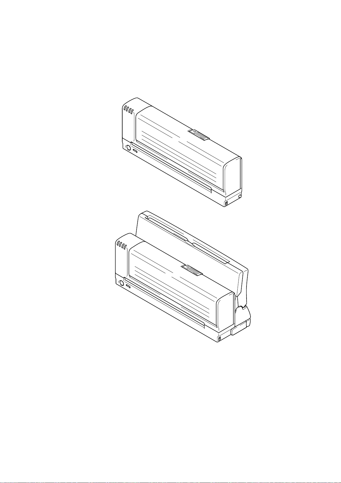
3. CONFIGURATION
3.1 Mechanics
< Overview >
MP-21C
MP-21CDX
Fig. 1.1
I-3
Page 12
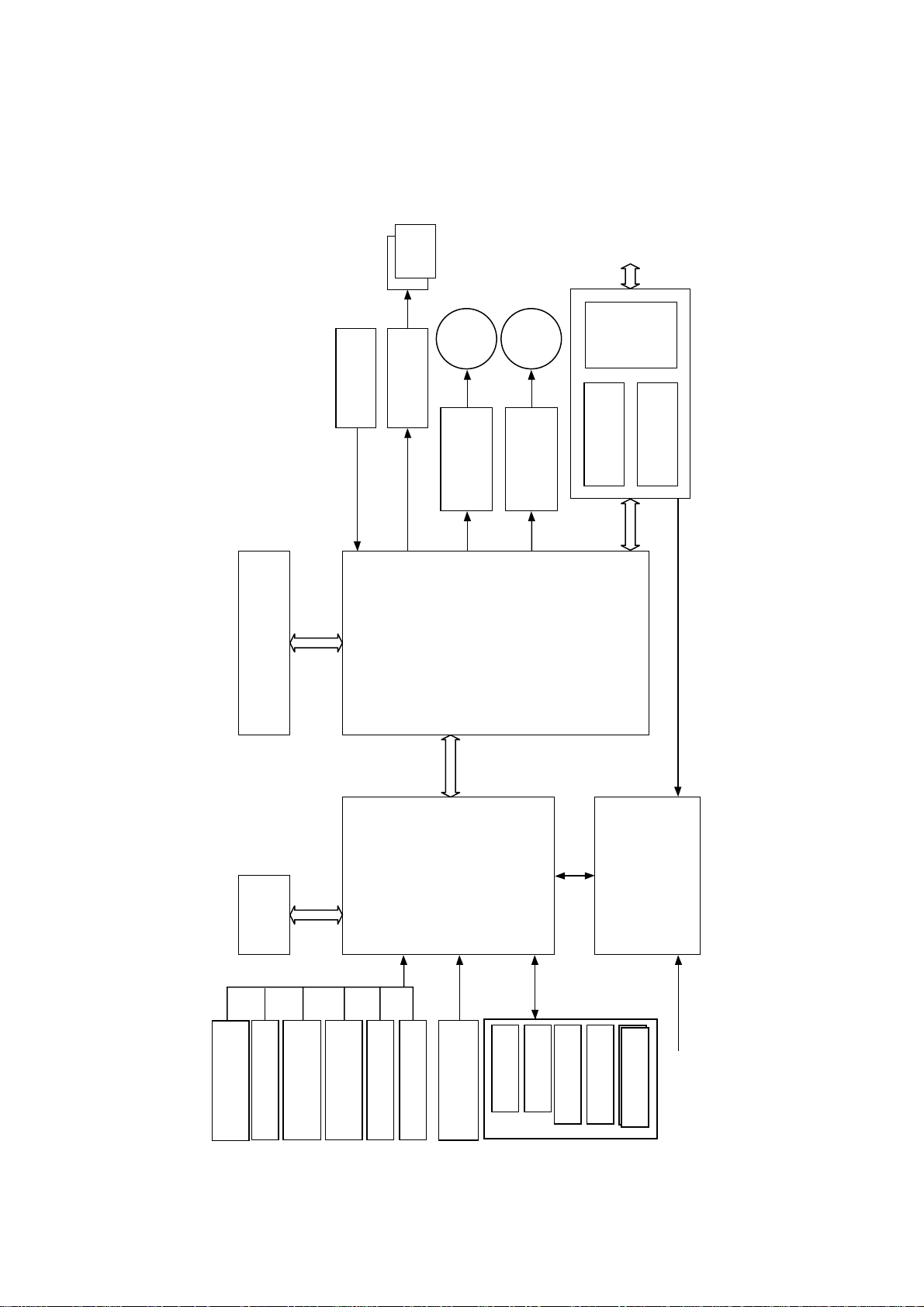
3.2 Electronics
The configuration diagram is as shown below.
Head
sensor
Linear encoder
Head driver
DC
motor
Stepping
driver
Stepping motor
motor
driver
DC motor
I/F
PCMCIA
controller
PCMCIA
controller
IEEE1284
PC card
EEPROM
Print buffer
SRAM
EEPROM
sensor
PE sensor
Paper eject
sensor
Purge unit
sensor
Ink cartridge
+ CR motor control
+ Encoder operation
G/A (upd99250GJ)
CPU (H8S)
ACSF sensor
+ LF motor control
+ IRQ
+ I/O
+ ROM
+ A/D
temperature
Head driver
Cover sensor
+ Head control
+ I/F control
+ Memory control
+ RAM
Power SW
Clean SW
Logic 1 (+3.3V)
Logic 2 (+5V)
DC/DC
LED (POWER)
LED (INK)
LED (ALARM)
+5V
Motor (+12V)
Head (13-30V)
AC adapter
Fig. 1.2
I-4
Page 13

4. SPECIFICATIONS
4.1 Printing
Print Method Piezotronic dot matrix ink jet
Head Nozzle 32 x 4 nozzles
Print Quality Super Fine / Normal / Draft
Resolution (V x H) 720 x 720 dots/inch (Super Fine)
Print Speed With Printer Interface Card:
PR99052, PR99062
360 x 360 dots/inch (Normal)
180 x 360 dots/inch (Draft)
Up to 107 cps at 10 cpi in normal or super fine print mode
Up to 1.3 PPM in normal or super fine print mode
Up to 1.7 PPM in draft print mode
Up to 2.1 PPM in Blue-Black draft print mode (A4)
Up to 2.2 PPM in Blue-Black draft print mode (Ltr)
With AC Adapter:
Up to 180 cps at 10 cpi
Up to 1.3 PPM in normal print mode
Up to 2.0 PPM in draft print mode
Up to 2.4 PPM in Blue-Black draft print mode (A4)
Up to 2.5 PPM in Blue-Black draft print mode (Ltr)
Print Width 203.2 mm (8 inches)
Print Media Liquid ink in cartridges
Life Expectancy of Printer 5 years or 10,000 pages
Ink Twin cartridge system: separate from the print head
Life Expectancy of Ink Black/Cyan (LC03BC): 250 pages/cartridge
4.2 Functions
Printer Driver Windows 3.1x/ 95/98/NT4.0
Emulation Windows GDI
Interface PCMCIA interface card
Control Panel 2 buttons and 4 LEDs
Diagnostics Self-diagnostics program at power on
Magenta/Yellow (LC03MY): 150 pages/cartridge
(When printing A4 or letter size at 5% coverage.)
Parallel interface (IEEE1284 compliant)
I-5
Page 14

4.3 Electrical and Mechanical
AC Adapter Power Source 100V model: AC 100 to 120 V, 60 Hz
Power Consumption Printer interface card Stand-by (Max.) 1.0 W
Noise Stand-by: 35 dB A or less
4.4 Environment
Temperature Operating: 10 to 35°C (50 to 95°F)
Humidity Operating: 20 to 80% (without condensation)
4.5 Dimensions and Weight
200V model: AC 220 to 240 V, 50 Hz
Printing (Max.) 4.2 W
Printing (Ave.) 2.5 W
Power save mode 0.6W
AC adapter Stand-by (Max.) 1.1 W
Printing (Max.) 4.5 W
Printing (Ave.) 3.2 W
Power save mode 0.7W
Printing: 40 dB A or less
Storage: -20 to 60°C (-4 to 140°F)
Storage: 5 to 95% (without condensation)
Dimensions (WxDxH) MP-21C: 50.8 x 300 x 106 mm (Without ACSF)
Weight MP-21C: Approx. 1,000g (2.2 lbs)
4.6 Recommended Paper
• Plain paper USA: Xerox 4200
• Special paper Brother Quality Coated Paper for 360dpi printing
Brother High Quality Coated Paper for 720dpi printing
Brother Color Inkjet Glossy Paper
Transparencies Brother Transparencies BPTRL (Letter)
MP-21CDX: 90 x 305 x 140 mm (With ACSF)
MP-21CDX: Approx. 1,460g (3.21 lbs)
Europe: Xerox Premier 80g/m
2
or equivalent
BP36CL (Letter), BP36CA (A4)
BP72CL (Letter), BP72CA (A4)
BPGLL (Letter), BPGLA (A4)
3M CG3410
3M CG3460 (For super fine mode)
I-6
Page 15
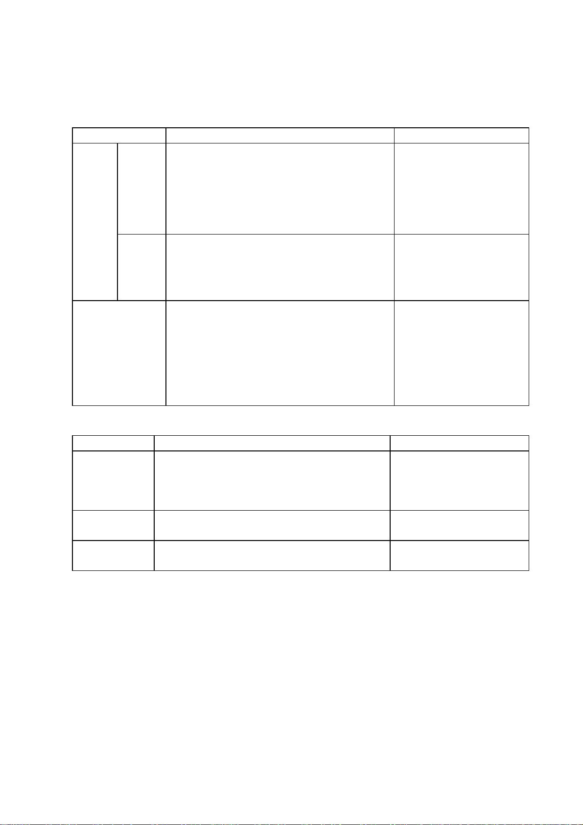
4.7 Paper Specification
The printer can handle plain paper, transparencies and envelopes that meet the following
specifications.
Feeder Paper Size Capacity
Manual
feed
ACSF
(MP-21CDX only)
Straight
paper
path slot
Paper
feeding
guide
Plain paper: A4, Letter, A5, Legal, Executive,
Envelope: DL, C5, B5, COM-10, Monarch, User defined
Coated paper: A4, Letter
Transparencies: A4, Letter
Organizer: K, L
(95.25 ~ 216 x 100 ~ 356 mm, 3.94 ~ 8.5 x 3.94 ~
14.02 inches, 60 ~ 157 g/m2, 16 ~ 42 lbs)
Plain paper: A4, Letter, A5, Legal, Executive
Transparencies: A4, Letter
Organizer: K, L
(95.25 ~ 216 x 100 ~ 356 mm, 3.94 ~ 8.5 x 3.94 ~
14.02 inches, 60 ~ 105 g/m2, 16 ~ 28 lbs)
Plain paper: A4, Letter, A5, Custom size
(100 ~ 216 x 100 ~ 356 mm, 3.94 ~ 8.5 x 3.94 ~14.02
inches, 60 ~ 105g/m2, 16 ~ 28 lbs)
* It is recommended to feed transparencies from the
straight paper path slot or the paper feeding guide.
Sheet by sheet
Sheet by sheet
Approx. 20 sheets of 75 g/m
•
~ 105g/m2 (20 lbs ~ 28 lbs)
plain paper (A4/Letter)
Approx. 30 sheets of 60 ~ 75
•
g/m2 (16 ~ 20 lbs) plain
paper (A4/Letter)
Approx. 20 sheets of Brother
•
coated paper (A4/Letter)
2
Cut Sheet Envelope
Caliper ± 0.03~± 0.08 in. (0.09 ~ 0.2mm) 0.0033 to 0.0058 in.
(0.084 to 0.14mm)
single thickness
Moisture 4% to 6% by weight 4% to 6% by weight
Smoothness 100 to 250 (Sheffield) 100 to 250 (Sheffield)
Remarks:
Avoid feeding labels. If the label jammed, glue may stick on the rollers
positioned on the way of the paper transportation pass and it may cause
further problems.
DO NOT
use ordinary transparencies designed for photocopiers or laser
printers. Use the recommended transparencies for the MP-21C/CDX
printers to obtain optimum print quality
If the paper will not feed from the ACSF, try the manual feed.
I-7
Page 16
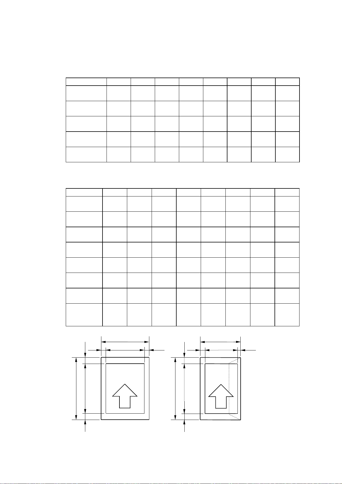
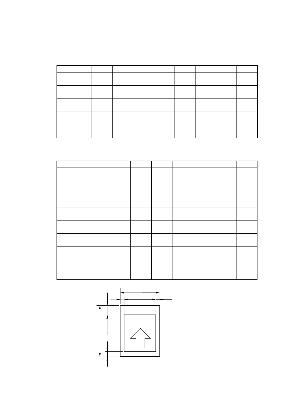
4.8 Printable Area
The table below shows the effective printable areas.
Plain paper
SIZE A B C D E F G H
A4 210.0
Letter 215.9
Legal 215.9
Executive 184.2
A5 148.5
Special paper
SIZE A B C D E F G H
Organizer K 95.25
Organizer L 139.7
B5* 176
C5* 162
MONARCH* 98.43
COM-10* 104.78
DL* 110
USER
DEFINED*
(8.2”)
(8.5")
(8.5")
(7.25")
(5.8”)
(3.75")
(5.5")
(6.9“)
(6.3“)
(3.8")
(4.1")
(4.3“)
215.9
(8.5“)
(Max.)
297.0
(11.5”)
279.4
(11.0")
355.6
(14.0")
266.7
(10.5")
210.0
(8.2”)
171.45
(6.75")
215.9
(8.5")
250
(9.8“)
229
(9.0“)
190.5
(7.5")
241.3
(9.5")
220
(8.6“)
355.6
(14.0“)
(Max.)
203.2
(8.0”)
203.2
(8.0”)
203.2
(8.0”)
177.4
(7.2”)
141.7
(5.5”)
88.45
(3.4“)
132.9
(5.2“)
169.2
(6.6“)
155.2
(6.1“)
91.63
(3.6“)
84.65
(3.3“)
103.2
(4.0“)
203.2
(8.0“)
282.5
(11.1”)
264.9
(10.4”)
341.1
(13.4”)
252.2
(9.9”)
195.5
(7.6”)
156.95
(6.1“)
201.4
(7.9“)
210
(9.2“)
180
(8.4“)
150.5
(6.9“)
201.3
(8.6“)
180
(7.0“)
341.1
(13.4“)
3.4
(0.13”)3(0.11”)
6.35
(0.25”)3(0.11”)
6.35
(0.25”)3(0.11”)
3.4
(0.13”)3(0.11”)
3.4
(0.13”)3(0.11”)
* : Envelope,
3.4
(0.13”)3(0.11”)
3.4
(0.13”)3(0.11”)
3.4
(0.13”)20(0.78”)
3.4
(0.13”)20(0.78”)
3.4
(0.13”)20(0.78”)
3.4
(0.39”)20(0.78”)
3.4
(0.13”)20(0.78”)
3.4
(0.13”)3(0.12”)
(Unit = mm)
3.4
(0.13”)
6.35
(0.25”)
6.35
(0.25”)
3.4
(0.13”)
3.4
(0.13”)
11.5
(0.45”)
11.5
(0.45”)
11.5
(0.45”)
11.5
(0.45”)
11.5
(0.45”)
(Unit = mm)
3.4
(0.13”)
3.4
(0.13”)
3.4
(0.13”)20(0.78”)
3.4
(0.13”)20(0.78”)
3.4
(0.13”)20(0.78”)
10.0
(0.39”)20(0.78”)
3.4
(0.13”)20(0.78”)
3.4
(0.13”)
11.5
(0.45”)
11.5
(0.45”)
11.5
(0.45”)
A
EG
F
C
Effective
printable area
E
F
A
C
Effective
printable area
G
A: Paper width
B: Paper length
C: Width
D
B
D
B
D: Length
E: Left margin
F: Top margin
G: Right margin
H
H
Fig. 1.3
H: Bottom margin
I-8
Page 17
The table below shows the recommended printable areas.
Plain paper
SIZE A’ B’ C’ D’ E’ F’ G’ H’
A4 210.0
(8.2”)
Letter 215.9
(8.5")
Legal 215.9
(8.5")
Executive 184.2
(7.25")
A5 148.5
(5.8”)
297.0
(11.5”)
279.4
(11.0")
341.1
(14.0")
266.7
(10.5")
210.0
(8.2”)
203.2
(8.0”)
203.2
(8.0”)
203.2
(8.0”)
177.4
(7.2”)
141.7
(5.5”)
265.5
(10.4”)
247.9
(9.7”)
324.1
(12.7”)
235.2
(9.2”)
178.5
(7.0”)
3.4
(0.13”)20(0.78”)
6.35
(0.25”)20(0.78”)
6.35
(0.25”)20(0.78”)
3.4
(0.13”)20(0.78”)
3.4
(0.13”)20(0.78”)
(0.13”)
(0.25”)
(0.25”)
(0.13”)
(0.13”)
Special paper
* : Envelope,
SIZE A B C D E F G H
Organizer K 95.25
(3.75")
Organizer L 139.7
(5.5")
B5* 176
(6.9“)
C5* 162
(6.3“)
MONARCH* 98.43
(3.8")
COM-10* 104.78
(4.1")
DL* 110
(4.3“)
USER
DEFINED*
215.9
(8.5“)
(Max.)
171.45
(6.75")
215.9
(8.5")
250
(9.8“)
229
(9.0“)
190.5
(7.5")
241.3
(9.5")
220
(8.6“)
355.6
(14.0“)
(Max.)
88.45
(3.4“)
132.9
(5.2“)
169.2
(6.6“)
155.2
(6.1“)
91.63
(3.6“)
84.65
(3.3“)
103.2
(4.0“)
203.2
(8.0“)
139.95
(5.4“)
184.4
(7.2“)
210
(8.2“)
180
(7.08“)
150.5
(5.9“)
201.3
(7.9“)
180
(7.08“)
324.1
(12.7“)
3.4
(0.13”)20(0.78”)
3.4
(0.13”)20(0.78”)
3.4
(0.13”)20(0.78”)
3.4
(0.13”)20(0.78”)
3.4
(0.13”)20(0.78”)
3.4
(0.39”)20(0.78”)
3.4
(0.13”)20(0.78”)
3.4
(0.13”)20(0.78”)
(0.13”)
(0.13”)
(0.13”)20(0.78”)
(0.13”)20(0.78”)
(0.13”)20(0.78”)
(0.39”)20(0.78”)
(0.13”)20(0.78”)
(0.13”)
(Unit = mm)
3.4
6.35
6.35
3.4
3.4
11.5
(0.45”)
11.5
(0.45”)
11.5
(0.45”)
11.5
(0.45”)
11.5
(0.45”)
(Unit = mm)
3.4
3.4
3.4
3.4
3.4
3.4
3.4
3.4
11.5
(0.45”)
11.5
(0.45”)
11.5
(0.45”)
A'
E' G'
F'
C'
A’: Paper width
B’: Paper length
C’: Width
Recommended
printable area
D'
B'
D’: Length
E’: Left margin
F’: Top margin
G’: Right margin
H’: Bottom margin
H'
Fig. 1.4
I-9
Page 18
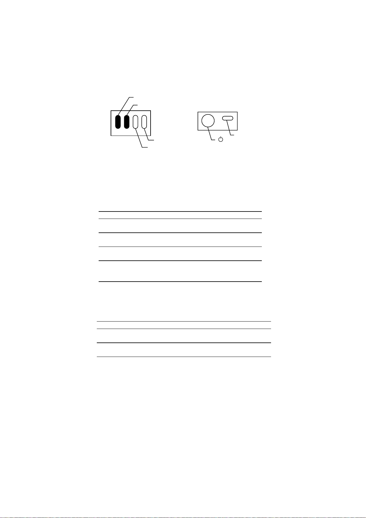
4.9 Control Panel (LEDs and Buttons)
This printer is equipped with a minimal control panel. Settings and status indication are
available on the printer driver status monitor.
The control panel includes the following LEDs and buttons.
< LEDs >
4.9.1 Power LED
The Power LED indicates the current power status of the printer.
LED Printer status
On
●
Off
❍
Blinking
❍↔●
Fast
Blinking
❍↔●
Power LED
Alarm LED
Ink (MY) LED
Ink (BC) LED
< Buttons >
Clean button
(On/Off) button
Fig. 1.5
The printer is turned on and ready to print.
The printer is turned off.
The printer is receiving data.
The printer is ready to feed paper.
(Only for manual paper feed)
4.9.2 Alarm LED
The Alarm LED indicates a printer error status.
LED Printer status
On
●
Blinking
❍↔●
When the Alarm LED is on or blinking and the printer has detected an error
condition,
problem to make the printer ready to print.
When Power LED + Alarm LED and Ink LEDs (BC LED+MY LED) Blink in Turn
The printer is making itself ready to print.
The printer is cleaning the print head.
When All the LEDs Blink at the Same Time
Service call occurred. Refer to Section 3.3.2 Service Calls in Chapter 4.
Paper empty, paper jam or mis-feeding. If a
paper jam occurs.
The Top cover of the printer is open and
should be closed so that the printer can print.
refer to Section 3.3 Error codes in Chapter 4 and clear the
I-10
Page 19

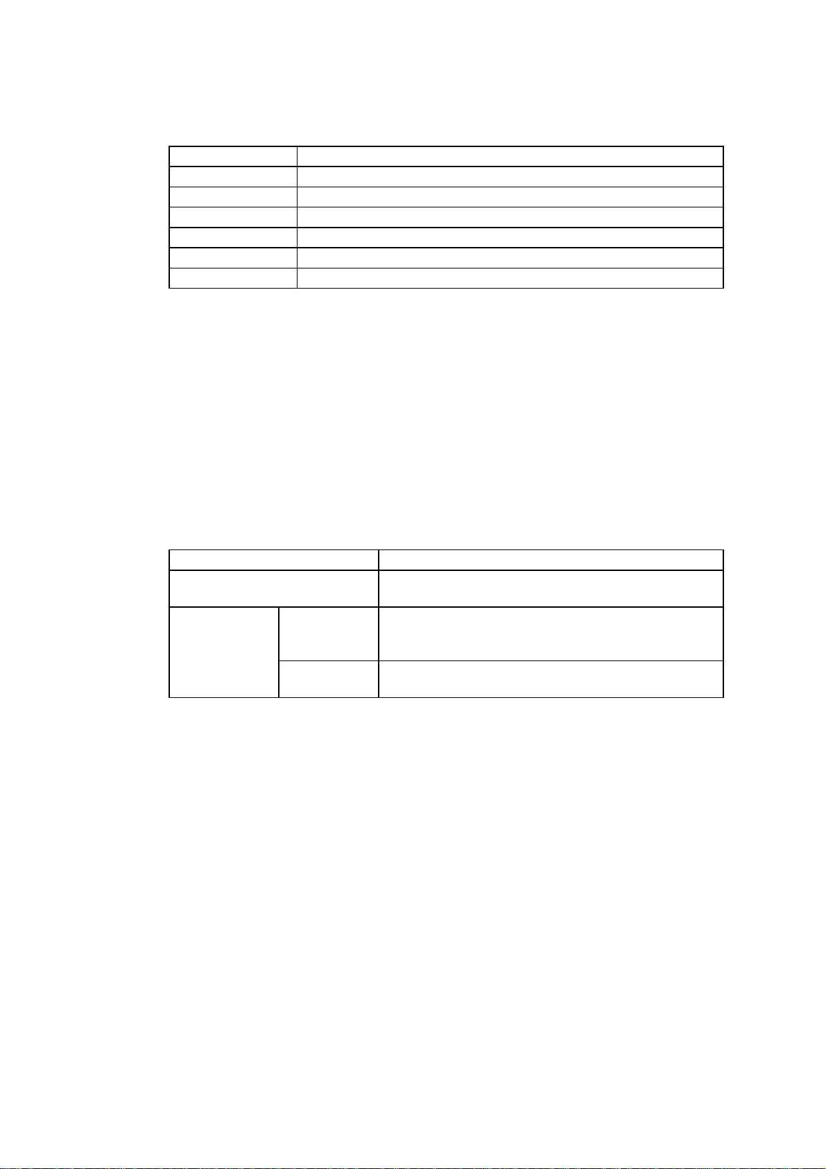
4.9.3 Ink LEDs (BC LED and MY LED)
Each Ink LED indicates when the ink is low or empty with the Alarm LED on.
LED Printer status
Blinking
❍↔●
On
●
The color ink cartridge is running out of ink. You
should prepare a new ink cartridge for that
color.
The color ink cartridge is empty. You should
replace it with a new one immediately for
optimum print quality. See Section 4.11
Replacing the ink cartridge in Chapter 1.
This may also indicate that one or more ink
cartridges may not be installed correctly.
4.9.4
4.9.5 Clean Button
(On/Off) / Retry Button
When you press this button and when the Power LED is on, the printer becomes ready to
operate.
When the Alarm LED is on with Power LED blinking, pressing this button will resume
printing. A paper jam or mis-feed will be cleared.
Make sure that the Power LED is on after you press this button.
When you want to clean the print head, press this button.
Note: Even if you turn the
(On/Off) button off, power is not completely shut off.
In case of emergency, you must remove the Printer Interface Card from the
computer and remove the AC Adapter from the mains if connected (MP21CDX or PA-21MP users only) in order to shut off power completely.
I-11
Page 20
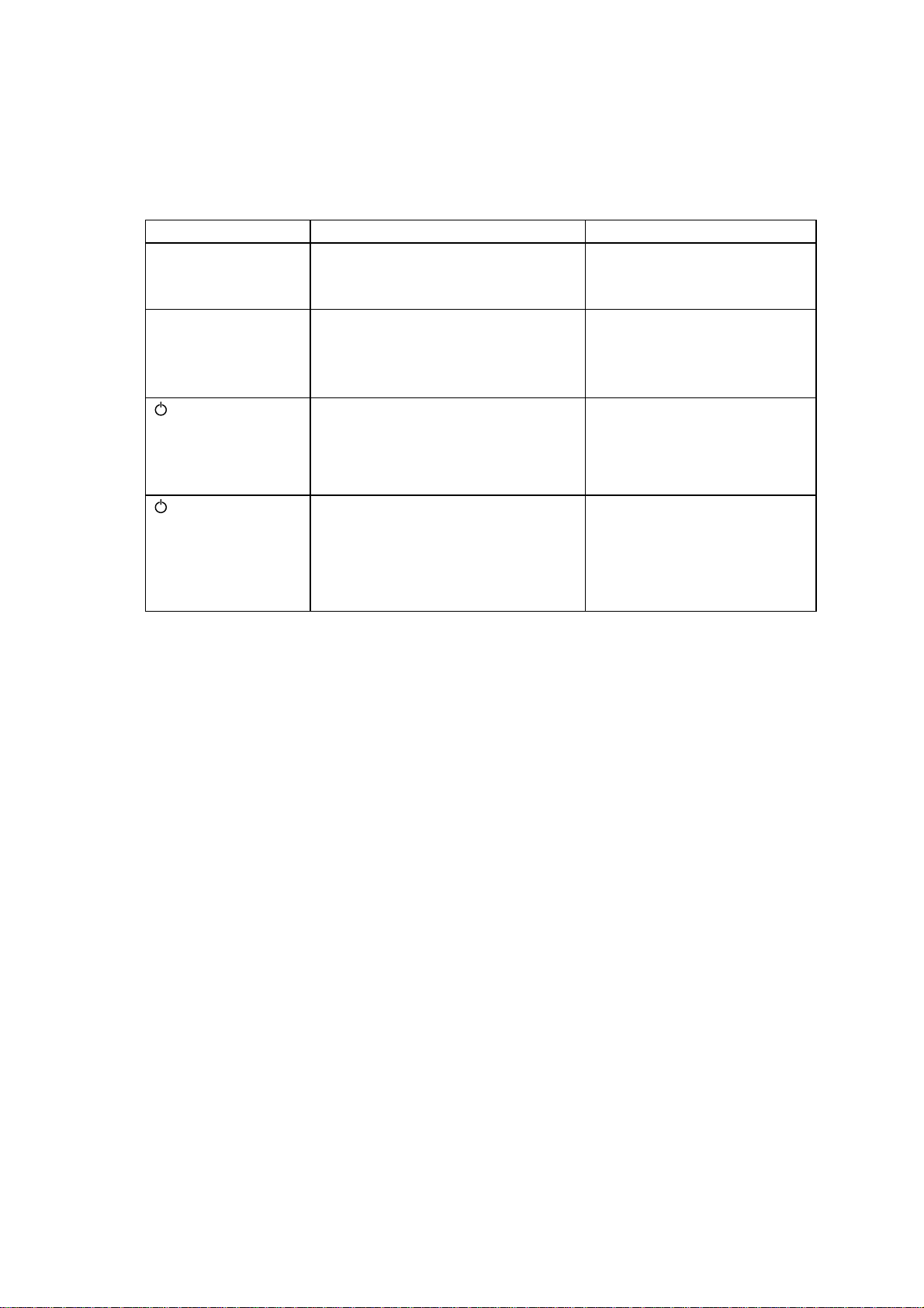
4.9.6 Printer Status
The table below shows the details of the various printer status conditions.
Status Description
Not energized Power is not supplied.
Power off Power is turned off (low power consumption mode).
Online Ready to receive data.
Operator call An operator call has occurred. It can be recovered by users
Cleaning The print head is cleaning.
Service call A service call has occurred.
The printer is energized up when you:
Insert the Printer Interface card in the PCMCIA slot with the PC powered on.
➀
Turn on the PC with the Printer Interface card inserted in the PCMCIA slot.
➁
Plug in the AC adapter jack to the printer.
➂
All the four LEDs flash once and they turned OFF, however the power is supplied to the
printer.
Any status indication that occurs when the printer is powered up with the power button
pressed is a hidden status.
The printer operates in the following 3 modes.
Mode Description
Normal mode After initialization and error detection are carried out,
Hidden
function mode
4.9.7 Control Panel
The control panel monitors the switches and sensors, as well as indicating the status on
the LEDs.
Switch status is detected after noise cancellation and switch debouncing. Data read for
two successive times detects the switch status (noise cancellation), then the current
status is defined after a further confirmation of three more switch reads.
LEDs turn off, light, or blink to indicate the printer status. Blinking includes 3 patterns:
4 LEDs blink at the same time,
Inspection
mode
PCB check
mode
the printer goes into normal print mode.
Initialization is not carried out on the mechanical
parts; mechanical operation is controlled using
commands and switches.
Mechanical operation is not performed; hardware
operation is checked.
4 LEDs blink alternately,
➁
* For factory use only *
* For factory use only *
3 LEDs blink successively.
➂
➀
I-12
Page 21

4.9.8 LEDs
The table below shows the LED indications.
Status
Not energized
Energized/Power OFF
Being initialized/Device being busy
Online No alarm
Receiving No alarm
data/Printing Ink near empty
Operator call Ink near empty
Cover open No alarm
Purging
Service call
Ink near empty
Ink empty
Ink empty
Ink empty
Ink near empty
Ink empty
(Power) (Alarm) (Ink BC) (Ink MY)
{{{{
zzzz
z
z
z
{
{
z
z
z
{{{
{
{
{{{
{
{
z
✩
/
{{
z
z
/
{{
zzz
{{
zz
✩
/
z
z
/
z
: Indicates an LED is ON
{
: Indicates an LED is OFF
,
When a service call has occurred, its error type and error code are indicated using 4 bits
(LED1 to LED4).
Refer to service codes for details. LED1 does not turn off during mechanical operation.
, ✩: Indicate an LED is blinking
,
(LEDs with the same symbol means that they blink at the same speed)
I-13
Page 22
4.9.9 Printer Status
(1) Not energized
This status means that power is not supplied to the printer.
The table below shows the printer operation when power is supplied.
Condition Printer operation Status
Power applied
Clean button pressed
then power applied
(On/Off) button
and Clean button
pressed
simultaneously, then
power applied
(On/Off) button
and Clean button
pressed
simultaneously with
the cover open, then
power applied
All the LEDs light, then turn off.
➀
Initializing for energizing
➁
Status
➂
All the LEDs light, then turn off.
➀
Initializing for energizing
➁
Initializing for turning on power
➂
Status
➃
All the LEDs light, then turn off.
➀
Initializing for energizing
➁
Initializing for turning on power
➂
Status
➃
All the LEDs light, then turn off.
➀
Initializing for energizing
➁
Initializing for turning on power
➂
Status
➃
Normal mode
Ready for power to be applied.
Preparing for printing test
Ready for power to be applied
Preparing for EEPROM reset
Ready for power to be applied
Process support mode
(2) Power off
This status is the power consumption save mode where only the control panel
operates.
<Buttons>
Power/Online button
Pressing this button allows the printer to become online and offline. When in
manual feed mode and there is no paper, the printer becomes offline and does not
print. If this happens when using the manual feed slot, load a sheet of paper, the
printer will detect the paper and start printing. If this happens when using the
ACSF, press this button after loading paper. The printer will then start printing.
4.10 How to Clean the Print Head - Purge
When you get white lines in text or graphics on your printed document, clean the print
head.
You can clean the 2 print heads by pressing the Clean button on the control panel.
1. Make sure the printer is Online with the Top cover closed.
2. Push the Clean button.
3. The printer starts cleaning the print head automatically. When the cleaning is
finished, the printer becomes online automatically.
Note: You can clean the print head from the printer driver. Select
[Control/Maintenance] tab from the MP-21C/MP-21CDX Windows printer
driver and click the [Maintenance] button.
I-14
Page 23
4.11 Replacing the Ink Cartridges
When the LED(s) shows an ink empty or an ink near empty status, replace the indicated
ink cartridge(s) with a new one. We strongly recommend you use Brother original ink
cartridges for the best print quality. Using other ink may void the warranty for this printer.
Black and Cyan No. LC03BC
Magenta and Yellow No. LC03MY
<How to replace the cartridges>
1. Make sure the
Power
LED is on.
2. Open the Top cover. Make sure the carriage is resting in the home position at the
right hand side of the printer.
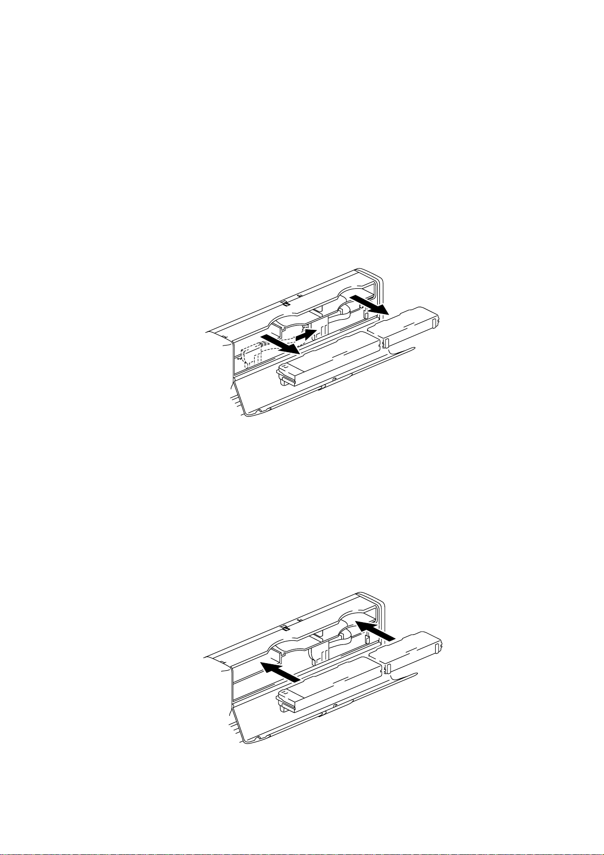
3. Pull out the empty ink cartridge in the direction of the arrow.
Note: Make sure that the Power LED is ON, otherwise the ink used counter will not
be cleared.
Fig. 1.6
Caution:DO NOT remove ink cartridges when you do not need to replace them.
Insert a new ink cartridge within a few seconds of taking out the empty ink
cartridge.
Once you have removed a cartridge, DO NOT attempt to re-use it.
4. Open the new ink cartridge box and take the cartridge out of the bag.
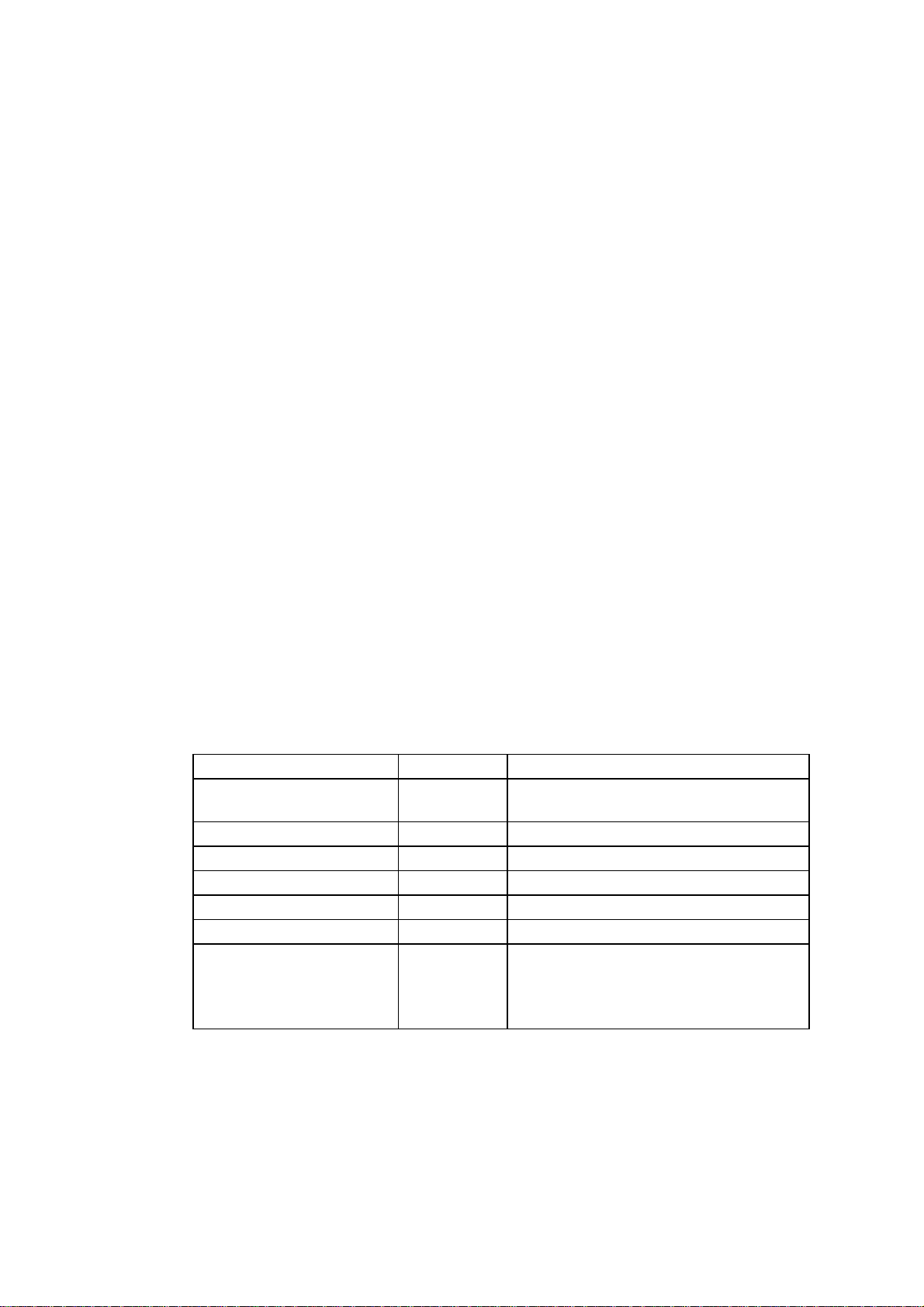
5. Insert the new cartridge, making sure to put it the correct position and push it until
it stops.
Fig. 1.7
I-15
Page 24
6. Close the Top cover. The printer will automatically start initial purge. When the
initial purge is done, the Power LED comes on.
Warning: If ink stains your body or clothing, wash with soap or detergent
immediately.
If ink gets in your eyes, irrigate them with water immediately and consult a
doctor if you are concerned.
Caution:Once you have installed the cartridge, DO NOT take it out until the ink empty
status is indicated as this may reduce the print quality.
Once you have opened an ink cartridge, use it up within 6 months.
Note: If an ink empty status still remain after you have installed the ink cartridges,
check that the ink cartridges are installed correctly.
Both the ink cartridge BC and the ink cartridge YM should be installed. A
printer with only one ink cartridge installed cannot perform printing
operations.
PR99052
4.12 Recovery Function - Purge
The purge operation is carried out just before the first print job when more than a certain
number of days have passed(see below) since the last purge was carried out. The printer
memorizes the time when the last purge was conducted in the EEPROM. When the
printer has been left with power off, the time and date is sent from the PC just before
printing by the printer driver. The printer conducts the designated purge by comparing
this date with the date of the last purge. To operate the automatic recovery function
correctly, the date of the PC needs be correct.
4.12.1 Definition of Terms
Purge type Abbrieviation Description
Single purge SP This is a normal purge. All colors are
Initial purge IP Single purge x 7 times
Double purge WP Single purge x 2 times
Triple purge TP Single purge x 3 times
Cartridge purge CP Single purge x 5 times
Power purge PP Single purge x 5 times
Manual purge MP The single purge begins by pressing the
purged.
Clean button on the control pane.
The single or power purge can be
executed from the printer driver.
I-16
Page 25
4.12.2 Automatic Purge
PR99052
Date condition Condition
First ink cartridges are
installed into a brandnew printer.
First automatic purge
after a new cartridge
installed and the
specified time has
passed with no print
operations.
Date defined purge 3-1
Only after the empty
cartridges are replaced
with new ones.
4.12.3 Manual Purge
Purge
type
1 IP Just after the ink cartridges
2-1
2-2
2-3
3-2
3-3
4CP
SP
WP
TP
SP
WP
TP
type
installation. The IP is carried out
only one time in the whole printer
life.
3 days
6 days
9 days
5 days
7 days
9 days
Time condition
Pressing the Clean button on the printer control panel or clicking the [Clean button on the
[Maintenance] of the Windows driver executes the purge.
How to execute Purge type Remark
Pressing the Clean button on the printer SP Only SP is available.
Clicking the [Clean] button in the Windows
printer driver
4.12.4 Automatic Purge Frequency
In case the manual purge was carried out 3 times by pressing the Clean button on the
control panel, the PP begins automatically and continuously after the 3rd single purge
finishes. The 3rd purge operation performs the single purge 6 times in total.
The special purge sequence starts when the two conditions below are achieved.
- The printer is powered ON, in the Ready status and is connected to a PC.
- Pressing the Clean button on the control panel 3 times within 1 hour.
Note: As the Windows printer driver sends a command to execute the PP, the
printer must be connected to a PC.
SP
PP
You can select SP or PP.
The number of manual purges executed by the Windows printer driver is not
counted.
I-17
Page 26

The number of automatic purges such as the date defined and cartridge
purge are ignored.
When the printer is in the following condition, the printer cannot detect that
the Clean button is pressed.
- The power is OFF.
- The printer is in a printing operation.
- The printer is performing a purge operation.
4.12.5 Purge Sequence
Print operations are performed everyday.
IP
SP SP SP
CP
SP
PR99052
SP
MP is performed before an automatic purge is carried out.
IP
MP
MP is performed after an automatic purge is carried out.
IP
SP
MP
In case no print operations are not performed in 6 days.
IP
SP
SP
WP SP
SP
In case no print operations
are not performed in 7 days.
CP
In case no print operations
are not performed in 9 days.
CP
WP
TP
SP
SP
I-18
Page 27

5. SAFETY INFORMATION
5.1 Ink Safety
Potential Health Effects
EYE CONTACT: May cause slight irritation.
SKIN CONTACT: Prolonged exposure may cause skin irritation.
INGESTION: Small amounts swallowed during normal handling operations are
not likely to cause injury; swallowing larger amounts may cause
injury.
INHALATION: Excessive vapor concentrations may cause irritation of respiratory
tract.
First Aid Measures
EYE CONTACT: Flash immediately with running water for at least 15 min.
If necessary, get medical attention.
SKIN CONTACT: Wash with water and soap or detergent.
INGESTION: Dilute with water and if necessary get medical attention.
(Never give anything by mouth to an unconscious person)
INHALATION: Remove to fresh air area.
Help with breathing and if necessary get medical attention.
6. CONSUMABLES AND ACCESSORIES
6.1 Brother Special Paper
• Quality Coated Paper for 360 dpi printing
Letter size No. BP36CL
A4 size No. BP36CA
• High Quality Coated Paper for 720 dpi printing
Letter size No. BP72CL
A4 size No. BP72CA
• Color Inkjet Glossy Paper for 720 dpi fine mode
Letter size No. BPGLL
A4 size No. BPGLA
6.2 Ink Cartridge
Black & Cyan ink cartridge No. LC03BC
Magenta & Yellow ink cartridge No. LC03MY
I-19
Page 28

6.3 AC Adapter, ACSF and Parallel I/F Cable
AC Adapter and Parallel I/F cable No. PA21MP
ASCF only No. SF21MP
PR99052
I-20
Page 29

Chapter II
THEORY OF OPERATION
Page 30

CONTENTS
1. GENERAL----------------------------------------------------------------------II-1
1.1 Normal Interlace Processing (360dpi) -----------------------------------------------II-1
1.2 Super Fine Interlace Processing (720dpi) ------------------------------------------II-2
2. ELECTRONICS -------------------------------------------------------------- II-3
2.1 General Block Diagram (MP-21C/MP-21CDX) ------------------------------------II-3
2.2 Electrical Configuration ------------------------------------------------------------------ II-4
2.3 Main PCB -----------------------------------------------------------------------------------II-5
2.3.1 Data Reception --------------------------------------------------------------------II-5
2.3.2 Control Panel -----------------------------------------------------------------------II-5
2.3.3 Paper Feed and Carriage Motor Drive Circuit ------------------------------ II-6
2.3.4 Paper Sensor -----------------------------------------------------------------------II-7
2.3.5 Cartridge Detection --------------------------------------------------------------- II-8
2.3.6 Head Voltage Control ------------------------------------------------------------ II-9
2.3.7 Home Position Detection of the Maintenance Mechanism -------------- II-9
2.3.8 Memory Circuit --------------------------------------------------------------------- II-9
2.4 Head PCB ---------------------------------------------------------------------------------- II-9
2.5 Carriage PCB ------------------------------------------------------------------------------II-9
2.6 Carriage Sensor PCB -------------------------------------------------------------------- II-9
2.7 Power Supply ---------------------------------------------------------------------------- II-10
PR99052
3. MECHANICS ---------------------------------------------------------------- II-11
3.1 Overview of Printing Mechanism ---------------------------------------------------- II-11
3.2 Print Head -------------------------------------------------------------------------------- II-12
3.3 Ink Cartridge ----------------------------------------------------------------------------- II-14
3.4 Head Maintenance Mechanism ----------------------------------------------------- II-15
3.4.1 Components and Functions -------------------------------------------------- II-15
3.4.2 Mechanism ----------------------------------------------------------------------- II-15
3.5 Sensors ----------------------------------------------------------------------------------- II-16
3.5.1 Top Cover Sensor --------------------------------------------------------------- II-16
3.5.2 Paper Feed Sensor, Paper Eject Sensor ---------------------------------- II-17
3.5.3 Maintenance Sensor (Purge Unit) ------------------------------------------- II-19
3.6 Carriage Drive Mechanism ----------------------------------------------------------- II-20
3.7 Paper Feed Mechanism --------------------------------------------------------------- II-21
Page 31

CHAPTER II THEORY OF OPERATION
1. GENERAL
1.1 Normal Interlace Processing (360dpi)
Fig. 2.1 below shows the relationship between the printing area and the line feed amount
for each print head pass.
pass 4
pass 1 (Position to start printing)
pass 2
pass 3
Interlace table 1
(Line feed amount)
124/1440
pass 4
pass 1
pass 2
Area covered by
the printing head
The printing operation is performed by repeating the following sequence:(120/1440 line feeding + 32 nozzle printing + 124/1440 line feeding + 32 nozzle printing +
124/1440 line feeding + 32 nozzle printing + 124/1440 line feeding + 62 nozzle printing +).
A buffer stores the data for each pass and interlace tables indicating how to allocate the
raster data for each pass are used for the printing operation.
To which pass (storing buffer) the binary raster data is loaded sequentially is allocated
and is initially determined according to the interlace table.
Interlace table 2
Interlace table 3
Interlace table 4
Fig. 2.1
124/1440
124/1440
124/1440
4 rasters of color print data and 1 raster of monochrome print data are converted to raster
graphics transfer commands (G/Z) and stored in the buffer. After the above conversion,
TIFF compression or mirroring is performed if necessary.
The number of rasters handled by each interlace table corresponds to the line feed
amount. Rasters are handled sequentially and the buffer store for sending commands for
1 pass is generated when the last raster of each table (the 1st raster of the next table in
normal and draft modes) is reached. Therefore, once data in the buffer is sent to the
printer with the line feed command (F), the buffer is initialized so that it will be ready for
use for later passes and processing of the next raster starts in the same manner.
II-1
Page 32

1.2 Super Fine Interlace Processing (720dpi)
This is a method to perform printing using nozzles moved at 4/360 inch pitch using
nozzles spaced at 2/360 inch pitch. Fig. 2.2 below shows the relationship between the
printing area and the line feed amount for each head print pass.
pass2
pass1 (Position to start to printing) (Line feed amount)
pass2
pass3
pass4
pass3
pass4
pass5
pass6
pass7
pass8
Area covered by
the printing head
pass5
pass6
pass7
pass8
pass1
pass2
Interlace table 1
Interlace table 2
Interlace table 3
Interlace table 4
Interlace table 5
Interlace table 6
Interlace table 7
Interlace table 8
Interlace table 1
Interlace table 2
Interlace table 3
Interlace table 4
Interlace table 5
Interlace table 6
Interlace table 7
Interlace table 8
62/1440
62/1440
62/1440
62/1440
62/1440
62/1440
62/1440
62/1440
62/1440
62/1440
62/1440
62/1440
62/1440
62/1440
62/1440
62/1440
Fig. 2.2
The printing operation is performed by repeating the following sequence:(30/720 line feeding + 30 nozzle printing + 30/720 line feeding + 30 nozzle printing +
30/720 line feeding + 30 nozzle printing + 33/720 line feeding + 30 nozzle printing +
30/720 line feeding + 30 nozzle printing + 30/720 line feeding + 30 nozzle printing +
30/720 line feeding + 30 nozzle printing + 27/720 line feeding + 30 nozzle printing +).
Detailed operations in the fine interlace processing are the same as those in the normal
interlace processing.
II-2
Page 33

2. ELECTRONICS
2.1 General Block Diagram (MP-21C/MP-21CDX)
Head
Stepping
sensor
Linear encoder
Head driver
Stepping motor
motor
driver
DC
motor
driver
DC motor
I/F
PCMCIA
controller
PCMCIA
controller
IEEE1284
PC card
EEPROM
Print buffer
SRAM
EEPROM
sensor
PE sensor
Paper eject
sensor
Purge unit
sensor
Ink cartridge
+ CR motor control
+ Encoder operation
G/A (upd99250GJ)
CPU (H8S)
ACSF sensor
+ LF motor control
+ IRQ
+ I/O
+ ROM
+ A/D
temperature
Head driver
Cover sensor
+ Head control
+ I/F control
+ Memory control
+ RAM
Power SW
Clean SW
Logic 1 (+3.3V)
Logic 2 (+5V)
DC/DC
LED (POWER)
LED (INK)
LED (ALARM)
+5V
Motor (+12V)
Head (13-30V)
AC adapter
Fig. 2.3
II-3
Page 34

2.2 Electrical Configuration
(1) Main PCB
• The Main PCB controls the following functions :
Data reception, Control panel control, Paper feed and carriage motor control,
Paper sensing, Cartridge detection, Head voltage control, Data transmission to
the head driver
• A one chip type CPU with a program of 128 KB is used.
• 2 buttons (the
(2) Head PCB
• The Head PCB has the following components
4 LEDs, 1 cover sensor
The head drive IC is on the Head PCB and is connected via 4 FPC cables from the
head unit.
The Head PCB is connected to the Head FFC cable.
(3) Carriage PCB
• The Carriage PCB has 1 linear encoder sensor.
• The Carriage PCB has a head temperature detect sensor.
PR99052
(On/Off) button and the Clean button) are on the Main PCB.
(4) DC/DC unit
• The power supply unit has the following functions :
3.3V or 5V power supply for the logic, 12V for the motor, 13 - 30V for the print
head.
(5) Cartridge sensor PCB
• The Cartridge sensor PCB has 2 cartridge sensors.
• This PCB is connected to the Head PCB via a harness.
II-4
Page 35

2.3 Main PCB
2.3.1 Data Reception
IEEE1284 bi-directional nibble mode is supported. The data reception operation is
performed by the gate array. The CINT-N signal from the gate array indicates the
reception of data to the CPU and control data is processed by the CPU. The printing
data is transmitted directly to the memory without being transmitted to the CPU.
#4 #7 #8 P8
SRAM
Parallel
I/F connector
2.3.2 Control Panel
The control panel controls two switch signal inputs and four LEDs. Two out of four LEDs
correspond to each of the ink cartridges. The cover switch is contained in the switch
panel. When this switch is OFF, the cover is open and printing is disabled. However,
operations associated with cartridge replacement with the cover open are allowed.
SW 1 on the Main PCB functions as the
and turns off the LEDs, but does not turn the power off.
ONLINE / Power SW
CPU
IPINT-N
CINT-N
G/A
SELECT IN-N
19
INPUTPRIME-N
18
Fig. 2.4
(On/Off) button and stops all the operations
P7
Purge SW
MHP Sensor
Maintenance
unit
P2
CPU
Fig. 2.5
II-5
COVER SW
5
11
LED POWER
LED ALARM
10
9
LED INKBC
8
LED INKMY
Page 36

2.3.3 Paper Feed and Carriage Motor Drive Circuit
A PM-type stepper motor is used to feed paper and is driven at a constant voltage. A DC
motor is used for the carriage. It uses the feedback signal (EINT-P) from the linear
encoder and its speed is controlled via the gate array by the CPU using the PWM control
method. The paper feed driving circuit is turned on and off by the M5VCNT signal from
the CPU.
#4
M5VCNT
#7
CPU
G/A
STPM0
STPM1
STPM0N
STPM1N
STPPWM0
STPPWM1
12V
#1
LF Driver
M54676
P1
To LF Motor
#4 #7
EINT-P
CPU
G/A
Fig. 2.6
DCM0
DCM1
DCM0N
DCM1N
Fig. 2.7
ENC 2-P
ENC 1-P
#2
#3
P6
To
Encoder sensor on
the carriage PCB
P4
To CR Motor
CR Drive motor
II-6
Page 37

2.3.4 Paper Sensor
The photo type sensor is contained on the Main PCB. The movable part of the
mechanism detects if there is paper or not and turns the sensor on and off. When light is
transmitted, there is no paper.
The CH1 level of the sensor output is less than 2.5V without paper and 2.5V or more with
paper present.
CPU
(
<Without paper>
Pin
)
PH1
Fig. 2.8
Movable tip
<With paper>
PH1
CPU
()
Movable tip
Pin
Main PCB Main PCB
Fig. 2.9
II-7
Page 38

2.3.5 Cartridge Detection
The detection switch is on the Cartridge PCB and detects the placement of each
cartridge separately. The detection signal is at a low level when a cartridge is fitted.
Fig. 2.10
• ACTRG and BCTRG are signals indicating the cartridges are fitted.
• SIN0-P, SIN1-P, SIN2-P, and SIN3-P are drive data (serial data) signals to the head
driver.
• HCLK-P and HSTB-P are the clock and shift signals of the drive data signals.
• HVDD is a head driving power supply voltage and is variable according to the output
of the thermistor (HDTHM-P signal) on the Head PCB.
• FIRE0-N, FIRE1-N, FIRE2-N, and FIRE3-N are signals setting the timing to apply the
head driving voltage to the head actuator. VDD1 is a signal indicating 5V to the head
driver and its state is controlled by the CPU according to the H5VCNT signal.
II-8
Page 39

2.3.6 Head Voltage Control
The head voltage varies with temperature and head ranks. The VSEL signal from the
CPU generates the HVDSEL signal indicating the analogue value which is transmitted
back to the power supply unit. The power supply unit outputs the head voltage (HVDD)
corresponding to the voltage of the HVDSEL signal.
Pin
#4 CPU
Fig. 2.11
2.3.7 Home Position Detection of the Maintenance Mechanism
MHPSENSOR is the position detection sensor of the maintenance mechanism. The
Home position of the mechanism is used during the purge sequence and is detected
when the power is turned on. (Refer to Fig. 2.5)
2.3.8 Memory Circuit
Location #7 is the LSI which is the gate array to control printing.
Location #8 is the static RAM of 1Mb.
Location #5 is the EEPROM.
Location #6 is the reset IC.
Location #5 and #6 are connected to the CPU.
Pin
)
(
2.4 Head PCB
4 LEDs, a cover switch, the head drive IC, 4 head FPC connectors and 2 cartridge
sensor connectors are contained on the Head PCB.
The connector CNI is connected to the Main PCB by an FFC cable.
Refer to the Head PCB circuit diagram.
2.5 Carriage PCB
The HEDR-8100 is the linear encoder sensor.
The PCB is connected to the Main PCB by an FPC cable.
Refer to the Carriage PCB circuit diagram.
2.6 Carriage sensor PCB
The connector is connected to the Head PCB.
II-9
Page 40

2.7 Power Supply
The power supply uses the switching regulation system to generate the regulated DC
power (+3.3V, +5V, +12V and HVDD), which are converted from the DC input.
(When HVDSEL is open)
Connector pin #1: NC
Connector pin #2 - #4: PCM5V
Connector pin #5 - #7: PCM5V RET
Connector pin #8: +5V
Connector pin #9: +3.3V
Connector pin #10, #11: SGND
Connector pin #12: HVDCUTOUT
Connector pin #13: ADPT
Connector pin #14: HVDSEL
Connector pin #15 - #16: P-RET
Connector pin #17: +12V
Connector pin #18: +24V
II-10
Page 41

3. MECHANICS
3.1 Overview of Printing Mechanism
Extension guide
Carriage ASSY
Paper eject roller
ASSY
Bottom cover
Power supply PCB
ACSF
Pick-up roller ASSY
Separation pad ASSY
Main roller ASSY
Fig. 2.12
II-11
Page 42

3.2 Print Head
,,
,,
,,,
,
,
,
,
,
,,
,
,
,
This is an on-demand ink jet printer and ejects ink by the firing of a piezoelectric ceramic
actuator. Refer to Fig. 2.13 for the print head structure. A narrow channel filled with ink is
sandwiched between two actuators. When a voltage is applied to an electrode formed on
the surface of the actuator, ink is pulled into the channel from the manifold with the
actuator deformed as shown in the Fig. 2.13. When the voltage becomes 0, the actuator
returns to the previous position and pressure is generated in the ink in the channel. Thus,
the nozzle ejects ink drops. Ink drops are propelled forwards by this action and are fired
onto the paper held by the platen and form dots of the respective color. This printer
incorporates thirty-two ink firing mechanisms per color as explained above, 2 colors per
head with 2 print heads, 126 in total.
Piezo
Dummy channelCeramic
Channel
Nozzle plate
Piezo
Fig. 2.13
< Head Specifications >
(1) Method PZT(Xaar) method with the dummy channel
(2) Driving frequency 3.85 KHz, 6.5 KHz, 7.7 Khz
(3) Injection droplet amount Normal mode :40 ± 5pl
Super fine mode :25 ± 2.5pl
(4) Composition Separate color type
(5) Number of ink 4 colors (Y/M/C/K)
(6) Number of nozzles 128 nozzles (32 nozzles x 4 colors)
Ink
Manifold
II-12
Page 43

(7) Nozzle layout
30/360"
31
30
160/360"
31
30
Head
PR99052
30/360"
31
31
30
30
2
1/90"
1/180"
2
1
1
0
0
Black Cyan
FWD PRINT
FWD FEED
2
1
0
Magenta Yellow
Fig. 2.14
(8) Driving voltage 13 V - 30 V
(The driving voltage is controlled according to the
head temperature see 2.3.6 Head Voltage
Control.)
(9) Driving pulse SP, SPT or SPIT
(No droplet gradation control)
Fire 3
2
1
0
Fire 2
Fire 1
Fire 0
µs
2
2
µs
2
µs
Overall cycle change ± 5 % or less
<When printing in the REV direction.>
(When printing is in the FWD is direction, the order of the Fire 3 to Fire 0 signals is
reversed.)
Fig. 2.15
II-13
Page 44

3.3 Ink Cartridge
Ink Cartridge BC
A liquid ink bag is placed inside the ink cartridge. By inserting the ink cartridge into the
printer, an ink needle punctures the seal and is inserted into the ink bag. Ink is supplied to
the print head through the ink needle and the ink tube. 3 needles in total stick into the Ink
cartridge BC. 2 of them are for the ink supply of Black and Cyan and the other one is for
the waste ink.
The spring plate which is placed over and under the ink bag applies pressure to the ink
bag in order to keep the most suitable internal pressure for printing.
When operating the purge system, the waste ink of all 4 colors is delivered from the
Purge unit ASSY to the waste ink absorber through the waste ink tube and needle.
Ink Cartridge MY
The basic structure of the Ink cartridge MY is the same as the Ink cartridge BC but there
is no waste ink absorber. The Magenta and Yellow waste ink is delivered to the waste
ink absorber inside the Ink cartridge BC, the ink cartridge MY does not have a waste ink
absorber. Therefore, only 2 needles stick into this cartridge.
PR99052
Liquid ink bag
Cap
Rib
Sealing
Ink cartridge BC Ink cartridge MY
Spring plate
Spring plate
Waste ink absorber
Cap
Rib
Rib
Fig. 2.16
Spring plate
Sealing
Spring plate
II-14
Page 45

3.4 Head Maintenance Mechanism
3.4.1 Components and Functions
(1) Suction Mechanism
Components : Suction cap, Pump, Maintenance cam
Functions : Guides ink to the head channel.
(2) Storage Mechanism
Components : Storage cap
Functions : Prevents the nozzle tip from drying out when it is
(3) Wiper Mechanism
Components : Wiper, Maintenance cam
Functions : Removes ink deposited on the nozzle surface
(4) Carriage Lock Mechanism
Components : Carriage locker, Maintenance cam
Functions : Aligns t h e s u ct i o n cap and the head for the
(5) Sensor
Components : Photo detector
Functions : Detects the Maintenance cam position.
Removes dry ink from around the nozzle.
Removes air and waste in the head channel.
Ejects sucked ink towards the ink absorber.
not printing.
after the ink has been purged by the suction
mechanism.
cleaning of each color.
Prevents carriage movement so that the head will
not move away from the storage cap when the
power is off.
3.4.2 Mechanisms
• The Maintenance cam connects the drive from the Paper feed motor to the Purge unit
ASSY and rotates it.
• The up-and-down movements of the suction cap, the cap, the wiper and the carriage
locker and suction and ejection operations of the pump are performed by one rotation of
the Maintenance cam.
(1) Suction Mechanism :
The suction cap is pressed on the nozzle plate by rotating the Maintenance cam.
After the cap is pressed onto the nozzle face, the piston in the pump is activated to
generate negative pressure in the pump. The negative pressure is sent to the
suction cap and ink is sucked from the head nozzle. The pump ejects the sucked
ink and feeds it into the waste ink foam of the Ink cartridge BC.
(2) Wiping Mechanism :
The wiper goes up after the suction mechanism has ejected the ink. When it
reaches the upper limit, the Maintenance cam stops rotating and the carriage
moves one head width and the wiper wipes the nozzle surface. After the wiping
operation, the carriage moves another head width distance and the wiper goes
down.
II-15
Page 46

(3) Storage mechanism :
The suction cap and the cap are pressed onto the nozzle plate by rotating the
Maintenance cam.
(4) Carriage Lock Mechanism :
The Maintenance cam rotates and the carriage lock pin goes up before the suction
operation to lock the carriage and goes down again before the wiping operation.
(5) Sensor :
The sensor is on during stand-by. It goes off when it detects the home position to
start the suction operation after the Maintenance cam rotates. The sensor goes on
after the suction, ejection and wiping operations.
3.5 Sensors
3.5.1 Top Cover Sensor
Cover sensor
Top cover
Fig. 2.17
II-16
Page 47

3.5.2 Paper Feed Sensor, Paper Eject sensor
The Paper feed/eject sensor actuator and a photo sensor detect whether there is paper
or not. The Paper feed/eject sensor actuator has a paper a sensing arm and the photo
sensor operating arm. When paper hits the paper sensing part as paper is ejected the
photo actuator arm goes up and detects the paper.
When the paper has ejected out of the printer, the Paper eject sensor actuator returns to
the former status and detects that there is no paper.
The Paper feed sensor detects;
• If a paper is inserted into the Straight paper path slot or the Paper feeding guide.
• The top edge of the paper which is fed from the ACSF
• The bottom edge of the paper
The Paper eject sensor detects;
• The top edge of the paper which is fed from the Straight paper path slot or the Paper
feeding guide
• The bottom edge of the paper
Pressure roller ASSY
Paper hold ASSY
Platen cover
Paper eject
sensor actuator
Paper feed sensor
Paper eject sensor
Main PCB
Paper
Fig. 2.18
Paper feeding can be from the Straight paper path slot or the Paper feeding guide. (Manual
feeding)
Paper feeding starts when the Paper feed sensor turns into ON. In a manual feeding, the paper is
fed until it hits the sensing point of the Paper eject sensor. If the Paper eject sensor turns ON, the
paper is continuously fed further to the print starting position. If not, a paper mis-pick error will be
detected.
Paper feeding from the ACSF
After the ACSF starts to pick-up the paper and the Paper feed sensor turns ON, the printer starts
the feeding operation. If the Paper eject sensor does not turn ON, the ACSF repeats the paper
pick-up operation twice more. If the Paper eject sensor stays in the OFF status after theses
additional retries, a paper miss-pick error will be detected.
II-17
Page 48

During printing
If the Paper feed sensor OFF states is detected (In case that a paper of different size from the one
selected on the printer driver is fed.), the printer stops printing and ejects the paper. The remaining
print data will be printed out on the next sheet.
Ejecting the paper
Upon finishing the print, the printer keeps the paper eject operation running until both the Paper
feed sensor and the Paper eject sensor go into the OFF status. During the paper eject operation, if
the Paper eject sensor does not turn OFF after the specified amount of paper feeding performed
after the Paper feed sensor returns to the OFF status, the printer feeds the paper intermittently. If
the Paper eject sensor still does not returns to OFF, a paper jam will be detected. When both the
Paper feed sensor and the Paper eject sensor do not returns the OFF condition in 30 sec. of the
paper feeding operation, the printer detects a paper jam has occurred.
II-18
Page 49

3.5.3 Maintenance Sensor (Purge Unit)
The Maintenance sensor uses a photo sensor to detect the home position of the
Maintenance cam.
The sensor is on during stand-by ( home position ) and goes off when the Maintenance
cam rotates and detects the Maintenance cam's position to start the suction operation.
The sensor goes on after the purge, ejection, wiping and capping operations are
completed.
Cylinder ASSY
Purge unit FFC
Maintenance cam
Head cap
Flushing foam R2
Flushing foam R1
Maintenance gear 10
Maintenance sensor
Fig. 2.19
II-19
Page 50

3.6 Carriage Drive Mechanism
The carriage motor controls horizontal movement of the carriage unit.
The motor rotation is transmitted to the timing belt via the motor pulley.
The guide shaft supports the carriage.
The carriage holds the timing belt.
The direction of the carriage motor rotation corresponds to the direction of the carriage
movement.
The position of the carriage is controlled by the encoder strip.
Carriage motor ASSY
Idle pulley
Timing belt
Carriage ASSY
Print head
Fig. 2.20
Guide bar
Encoder strip
Drive pulley
Carriage guide
II-20
Page 51

3.7 Paper Feed Mechanism
ACSF (MP-21C option)
When the line feed motor is driven in the reverse direction (reverse rotation) to the normal
paper feeding direction, the change-over 1 frame moves to engage the separation roller
gear via the idler gear. The separation roller rotates in the paper separation direction
(normal rotation) and separates a sheet of paper. The separation roller rotates with the
paper feeding operation and returns to the initial position and is registered by the paper
feed pressure spring behind the separation roller gear.
Separated paper is fed to the contact point of the Main roller and the Pressure roller by
the Pick-up roller where the top of the paper is registered.
After the paper is registered, the Paper feed motor is driven in the paper feeding direction
(normal rotation) and paper is fed by the Main roller and the Pressure roller.
After printing, paper is ejected by the Paper eject roller and the Star wheels.
Paper
Pick-up roller ASSY
Separation pad ASSY
Fig. 2.21
II-21
Page 52

Chapter III
DISASSEMBLY AND
REASSEMBLY
Page 53

CONTENTS
1. PRECAUTIONS-------------------------------------------------------------- III-1
1.1 Safety Precautions --------------------------------------------------------------------- III-1
1.2 Attention ---------------------------------------------------------------------------------- III-1
2. TIGHTENING TORQUE LIST-------------------------------------------- III-2
3. DISASSEMBLY ORDER FLOW ---------------------------------------- III-3
4. DISASSEMBLING AND REASSEMBLING PROCEDURE------ III-4
4.1 Ink Cartridge, ACSF-------------------------------------------------------------------- III-4
4.2 Top Cover, Paper Guide, Front Cover, Release Plate, Rear Cover ------- III-5
4.2.1 Top Cover ------------------------------------------------------------------------ III-5
4.2.2 Paper Guide --------------------------------------------------------------------- III-5
4.2.3 Front Cover ---------------------------------------------------------------------- III-6
4.2.4 Release Plate ------------------------------------------------------------------- III-7
4.2.5 Rear Cover ----------------------------------------------------------------------- III-7
4.3 Head PCB ASSY ----------------------------------------------------------------------- III-8
4.4 Ink Head Base Unit, Print Head ----------------------------------------------------- III-9
4.5 Bottom Cover ---------------------------------------------------------------------------III-12
4.6 Main PCB, Power Supply PCB ASSY --------------------------------------------III-14
4.7 Paper Feed Motor ASSY ------------------------------------------------------------III-16
4.8 Purge Unit ASSY ----------------------------------------------------------------------III-18
4.8.1 Flushing Foam R1 and R2---------------------------------------------------III-20
4.9 Paper Feed Frame ASSY -----------------------------------------------------------III-22
4.9.1 Paper Feed Motor Holder ---------------------------------------------------III-22
4.9.2 Arm Stopper --------------------------------------------------------------------III-23
4.9.3 Paper Eject Idle Gear 25 ----------------------------------------------------III-24
4.9.4 Carriage Guide -----------------------------------------------------------------III-24
4.9.5 Paper Eject Roller ASSY ----------------------------------------------------III-25
4.9.6 Platen Cover, Flushing Foam L1 and L2 ---------------------------------III-26
4.9.7 Main Roller ASSY -------------------------------------------------------------III-29
4.9.8 Encoder Strip -------------------------------------------------------------------III-33
4.10 ACSF -----------------------------------------------------------------------------------III-34
4.10.1 ACSF Support ----------------------------------------------------------------III-34
4.10.2 Pick-Up Roller Cover --------------------------------------------------------III-34
4.10.3 ACSF Front Cover, Pick-Up Roller ASSY, Gear Frame R ---------III-35
4.10.4 Separation Pad ASSY ------------------------------------------------------III-36
4.10.5 Extension Guide L and R --------------------------------------------------III-37
5. LUBRICATION -------------------------------------------------------------III-38
6. CLEANING THE PRINTER ---------------------------------------------III-43
6.1 Cleaning The Platen Cover ---------------------------------------------------------III-43
6.2 Cleaning The Edge Of The Head Cap -------------------------------------------III-43
6.3 Cleaning The Pick-up Roller On The ACSF ------------------------------------III-44
7. PACKING---------------------------------------------------------------------III-45
Page 54

CHAPTER III DISASSEMBLY AND REASSEMBLY
1. PRECAUTIONS
1.1 Safety Precautions
(1) Always turn off the
accessing any parts inside the printer.
Note: Even if you turn the (On/Off) button off, the power is not completely shut
(2) The ink contains no harmful substances.
a. If the ink stains your body or clothes, wash with soap or detergent immediately.
b. If the ink gets in your eyes, irrigate them with water immediately and consult a
doctor if you are concerned.
c. If you swallow the ink by accident, drink plenty of water and consult a doctor if
you are concerned.
(3) Do not put your hands into the printer while it is printing in order to avoid getting
hurt.
1.2 Attention
(1) Be careful not to lose screws, washers or other parts removed during the following
operations.
(2) Be sure to apply grease to the gears and applicable positions specified in this
chapter.
(3) When using soldering irons or other heat-generating tools, take care not to
damage parts such as cables, PCBs and covers.
(4) Before handling the PCBs, touch a metal portion of the equipment to discharge any
static electric charge in your body, or the electronic parts or components may be
damaged.
(5) When transporting PCBs, be sure to wrap them in the correct protective packaging.
(6) Be sure to replace self-tapping screws correctly, if removed. Unless otherwise
specified, tighten screws to the torque values listed in Section 2 below.
(7) When connecting or disconnecting cable connectors, hold the connector body, not
the cables. If the connector has a lock, release the connector lock first to unlock it.
(8) After a repair, check not only the repaired portion but also that the connectors and
other related portions are functioning properly before an operational check.
(9) Make sure the printer has the ink cartridge filter cover fitted before shipping.
(10) Make sure the print head has the filter cover and the nozzle protector fitted when
shipping the print head separately
(11) Special precautions are necessary when handling the print head.
a. Do not touch the nozzle plate, the manifold and the dimple contact of the Head PCB
ASSY.
b. Do not leave the print head with the nozzle plate and the manifold uncovered.
(On/Off and Online) button and unplug the power cord before
off.
III-1
Page 55

2. TIGHTENING TORQUE LIST
Location Screw type Q’ty Tightening
torque (kgf•cm)
Front cover Screw, bind M2.6x4
(Black)
Rear cover Screw, bind M2.6x4
(Black)
Bottom cover Screw, bind M2.6x4
(Black)
I/F connector Precision screw, M16x4 2
Waste ink needle Screw, bind B M2x6 1
Ink head base unit Taptite, bind M26x4 2
Print head Screw, bind B M2x8 2
Paper feed motor ASSY Taptite, bind M26x4 2
Purge unit ASSY Taptite, bind B M3x6 4
Paper feed motor holder Taptite, bind M26x4 1
Gear shaft 4 calking ASSY Taptite, bind M26x4 1 4.5 ± 1 Min. 2
Gear frame R (ACSF) Taptite, bind B M3x8 2
Extension guide L (ACSF) Taptite, bind B M3x8 2
Extension guide R (ACSF) Taptite, bind B M3x8 2
1
1
4
4.5 ± 1
4.5 ± 1
4.5 ± 1
0.7 ± 0.1
1.5 ± 0.5
4.5 ± 1
2 ± 1
4.5 ± 1
4 ± 1
4.5 ± 1
4 ± 1
4 ± 1
4 ± 1
Loosing torque
(kgf•cm)
Min. 2.5
Min. 2.5
Min. 2.5
Min. 0.5
Min. 0.5
Min. 2.5
Min. 1
Min. 2
Min. 1.5
Min. 2
Min. 1.5
Min. 1.5
Min. 1.5
III-2
Page 56

3. DISASSEMBLY ORDER FLOW
4.1 ACSF
4.10.1 ACSF Support
4.10.2 Pick-up Roller Cover
4.10.3 ACSF Front Cover
Pick-up Roller ASSY
Gear Frame R
4.10.4 Separation Pad ASSY
4.10.5 Extension Guide L and R
4.2 Top Cover
Paper Guide
Front Cover
Rear Cover
Release Plate
4.3 Head PCB ASSY
Cover Sensor Actuator
4.4 Ink Head Base Unit
Print Head
4.7 Paper Feed Motor ASSY
4.8 Purge Unit ASSY
4.8.1 Flushing Foam R1 and R2
4.1 Ink Cartridge BC
Ink Cartridge MY
4.5 Bottom Cover
4.6 Main PCB ASSY
Power Supply PCB ASSY
4.9.1 Paper Feed Motor Holder
4.9.2 Arm Stopper
4.9.3 Paper Eject Idle Gear 25
4.9.4 Carriage Guide
4.9.5 Paper Eject Roller ASSY
4.9.6 Platen Cover
Flushing Foam L1 and L2
4.9.7 Main Roller ASSY
4.9.8 Encoder Strip
III-3
Page 57

4. DISASSEMBLY AND REASSEMBLY PROCEDURE
Note: Reassembly is the reverse of Disassembly unless otherwise stated.
Please refer to the Notes relating to Reassembly information.
4.1 Ink Cartridge, ACSF (For MP-21CDX Only)
<Disassembly>
(1) For MP-21CDX, remove the ACSF.
(2) Connect the power cord to the printer, then turn the power on. Release the
Carriage ASSY from the sealing cap using the Service software tool.
(3) Remove the Ink cartridges BC and MY from the printer.
Note: After removing the Ink cartridges, DO NOT apply any vibration to the printer
in order to prevent ink from leaking out of the Print head.
Carriage ASSY
Front cover
Fig. 3.1
Ink cartridge MY
Ink cartridge BC
III-4
Page 58

4.2 Top Cover, Paper Guide, Front Cover, Release Plate, Rear Cover
4.2.1 Top Cover
<Disassembly>
(1) Remove the Top cover from the Front cover.
Note: This is only necessary if the Top cover requires replacement, otherwise it
should be removed with the Front cover as described in section 4.2.3.
Front cover
Fig. 3.2
Top cover
4.2.2 Paper Guide
<Disassembly>
(1) Remove the Paper guide from the Platen cover.
Rear cover
Paper guide
Fig. 3.3
III-5
Page 59

4.2.3 Front Cover
<Disassembly>
(1) Remove the screw securing the Front cover.
(2) Press the Front cover hook to release the lock, then remove the Front cover.
Note: Check that the Top cover sensor lever is attached to the Front cover.
Hook
Rear cover
Front cover
Front cover
Screw, bind M2.6x4 (Black)
Hook
Hook
Top cover sensor lever
Fig. 3.4
III-6
Page 60

4.2.4 Release Plate
<Disassembly>
(1) Lower the Release plate, then remove it by pulling it to the right.
4.2.5 Rear Cover
Release plate
Fig. 3.5
<Disassembly>
(1) Remove the screw.
(2) Remove the Rear cover by releasing the two hooks by which the Rear cover is
assembled onto the Bottom cover and then release the hook at the top of the Rear
cover.
Screw, bind M2x4
(Black)
Shutter frame
Hook
Hook
Rear cover
Hook
Fig. 3.6
III-7
Page 61

4.3 Head PCB ASSY
<Disassembly>
(1) Unlock and remove the Head FFC cable (the other end is connected to the Main
PCB ASSY) from the connector on the Head PCB ASSY.
(2) Unlock and remove the four Head FPC cables from the connectors one at a time.
(3) Remove the Cartridge sensor connector 3P from the connector on the Head PCB
ASSY.
Head FPC
Head FFC
Cartridge sensor connector 3P
Head PCB ASSY
Chassis L
Fig. 3.7
(4) Lifting the outer edge of the PCB, remove the Head PCB ASSY while pulling the
hook securing the Head PCB ASSY outwards.
Ink head base unit
Hook
Head PCB ASSY
Fig. 3.8
III-8
Page 62

(5) Remove the Cover sensor actuator from the Ink head base unit.
Cover sensor actuator
Cover sensor
actuator spring
4.4 Ink Head Base unit, Print Head
Ink head base unit
Fig. 3.9
Note: After replacing Print head, adjustment is need by using the Service
software tool.
<Disassembly>
(1) Remove the screw securing the Waste ink needle. (It is fitted nearest to the
removed Head PCB ASSY position.) Release the Waste ink tube from the three
hooks.
Note: Use caution when handling the Waste ink needle; it may cause you injury.
Screw, bind B 2X6
Waste ink needle
Fig. 3.10
III-9
Page 63

(2) Remove the two screws securing the Ink head base unit. Remove the Ink head
base unit from the Chassis center ASSY by lifting the left hand end of the Ink head
base unit then moving it to the left to release the hooks at the right hand end.
Screw, bind M26x4
Ink head base unit
Shutter
Hook
Boss
Fig. 3.11
<Reassembly>
Note: When replacing the Ink head base unit, be sure to remove the four
protective parts fitted on the Ink needles, which are positioned behind the
shutters.
(3) Supporting the Ink head base unit, move the Carriage ASSY to the position
indicated in the illustration below. Remove the two screws, then remove the Print
head and the Ink head base unit together from the Carriage ASSY.
Screw, bind M2x8
Print head
Chassis center ASSY
Carriage ASSY
Carriage guide
Carriage ASSY
Fig. 3.12
III-10
Page 64

<Reassembly>
Note: Be sure to slightly push the Print head towards the front of the printer, when
securing the Print head with the screws.
PR99066
< Back of the printer >
PUSH
< Front of the printer >
Print head
(4) Insert the Print head into the Nozzle protector.
Note: Check that the Print head is fitted correctly in the Nozzle protector.
Print head
Nozzle protector
<Reassembly>
Note: Check that the Carriage guide is fitted in the groove of the Carriage ASSY.
Refer to Fig. 3.12.
Fig. 3.13
III-11
Page 65

4.5 Bottom Cover
<Disassembly>
(1) Remove the two screws from the Interface connector using a precision
screwdriver.
Bottom cover
Precise screw, M16x4
Interface connector
Fig. 3.14
(2) Turn the printer upside down. Remove the four screws.
Bottom cover
Screw, bind M2.6x4
(Black)
Screw, bind M2.6x4 (Black)
Fig. 3.15
III-12
Page 66

(3) Lift up the Bottom cover. Turn it over, then place it down next to the Paper feed
frame ASSY
Note: DO NOT apply any stress to the harnesses connected to the Main PCB
ASSY.
Bottom cover
Main PCB ASSY
Fig. 3.16
(4) Remove the Carriage motor harness 2P, Paper feed motor harness 4P,
Maintenance sensor FFC 3P, and Encoder FFC 5P from the Main PCB ASSY.
Encoder FFC 5P
Paper feed motor harness 4P
Carriage motor harness 2P
Main PCB ASSY
Maintenance sensor FFC 3P
Bottom cover
Head FFC
Fig. 3.17
<Reassembly>
Note: When attaching the Bottom cover to the printer, check that the Carriage
motor harness 2P is not caught between the Chassis R and the Bottom
cover.
III-13
Page 67

4.6 Main PCB ASSY, Power Supply PCB ASSY
Note: After replacing Main PCB ASSY, adjustment is need by using the
Service software tool.
<Disassembly>
(1) Remove the Power supply FFC cable (which is connecting the Main PCB ASSY
and Power supply PCB ASSY) from the connector on the Main PCB ASSY.
(2) Remove the Main PCB ASSY from the Bottom cover by releasing the four hooks.
(3) Release the lock of the Head FFC cable connector (which is connecting the Main
PCB ASSY and Head PCB ASSY), then remove it from the connector on the Main
PCB ASSY.
Head FFC
Head PCB ASSY
Main PCB ASSY
Head FFC
Hook
Fig. 3.18
Hook
Bottom cover
Power supply PCB ASSY
Power supply FFC
Hook
Hook
III-14
Page 68

(4) Remove the Power supply PCB ASSY from the Bottom cover by releasing the four
hooks.
(5) Unlock and remove the Power supply FFC from the connector on the Power
supply PCB ASSY.
Power supply FFC
<Reassembly>
Note: Insert the Power supply FFC into the connector on the Main PCB ASSY,
with the terminals facing upwards.
After inserting the Head FFC into the connector on the Main PCB ASSY,
lock the connector.
Hook
Hook
Power supply PCB ASSY
Bottom cover
Hook
Hook
Fig. 3.19
III-15
Page 69

4.7 Paper Feed Motor ASSY
<Disassembly>
(1) Remove the Carriage motor harness 2P and Paper feed motor harness 4P from
the two hooks of the Purge unit ASSY, then carefully unstick the harnesses from
the double-sided adhesive tape.
Double-sided adhesive Tape
Hook
Carriage motor harness 2P
Hook
Paper feed motor harness 4P
Purge unit ASSY
<Reassembly>
Note: After attaching the Carriage motor harness 2P and Paper feed motor
harness 4P to the double-sided adhesive tape, secure the Purge unit FFC
cable with the hook .
Attach the Carriage motor harness 2P and Paper feed motor harness 4P to
the double-sided adhesive tape so that they DO NOT overlap each other.
DO NOT fold the Purge unit FFC cable.
When attaching the Bottom cover to the printer, check that the Carriage
motor harness 2P is not caught between the Chassis R and the Bottom
cover.
Purge unit FFC
Fig. 3.20
III-16
Page 70

(2) Remove the two screws, then remove the Paper feed motor ASSY from the Paper
feed motor holder.
Chassis R
Paper feed motor connector
Taptite, bind M26x4
Paper feed motor ASSY
<Reassembly>
Note: Mount the Paper feed motor ASSY on the Paper feed motor holder, with the
Paper feed motor connector to the right.
(3) Remove the Paper feed motor ASSY from the Paper feed motor holder.
Fig. 3.21
III-17
Page 71

4.8 Purge Unit ASSY, Flushing Form R1 and R2
<Disassembly>
(1) Unstick the Encoder FFC cable 5P from the double-sided adhesive tape attached
to the Purge unit ASSY.
(2) Remove the four screws and the Support plate from the Purge unit ASSY.
Encoder FFC 5P
Taptite, bind B M3X6
Support plate
Purge unit ASSY
Taptite, bind B M3X6
Double-sided adhesive Tape
(3) Remove the Waste ink tube from the two hooks.
Caution:Use caution when handling the Waste ink tube; the Waste ink needle at the
(4) While lifting the Purge unit ASSY, remove the Maintenance gear 10 from the
Note: Place the removed Purge unit ASSY with the Waste ink absorber face up.
Waste ink tube
Waste ink needle
Fig. 3.22
end of the Waste ink tube may cause you injury.
Bearing in the Chassis R.
Use caution when handling the Purge unit ASSY to prevent ink leakage.
Purge unit ASSY
Bearing
Boss
ACSF sensor actuator
Fig. 3.23
III-18
Maintenance gear 10
Page 72

<Reassembly>
Important:Check that the Waste ink tube is fitted correctly in the guides and goes
into the hole on the Purge unit ASSY
Purge unit ASSY
Waste ink tube
Fig. 3.25
Purge unit ASSY
Waste ink tube
Important:Check that the Waste ink tube is fitted correctly into the three guides and
two hooks on the Platen cover.
Waste ink tube
ACSF sensor actuator
Two hooks
Three guides
The Waste ink tube is not fitted in any of the guides and hooks.
The Waste ink tube is across the ACSF sensor actuator.
Platen cover
The Waste ink tube is caught between the Platen cover and
Chassis center ASSY.
Fig. 3.26
III-19
Page 73

Important:Before reassembling the Purge unit ASSY to the Platen cover, be sure to;
- Align the notches of the Purge cam and Purge unit frame.
- Fit the protrusion of the Maintenance gear 10 in the notch of the
Maintenance idle gear 20.
- Insert the boss of the Maintenance gear 10 into the bearing of the
Chassis R. (Refer to Fig. 3.23.)
Maintenance gear 10
Platen cover
Protrusion
Notch
Maintenance idle gear 20
Purge unit ASSY
Purge unit frame
Purge cam
4.8.1 Flushing Foam R1 and R2
<Disassembly>
(1) Remove the Flushing foam R1 and R2 from the Purge unit ASSY.
Purge unit ASSY
Fig. 3.27
Flushing foam R2
Flushing foam R1
Fig. 3.24
III-20
Page 74

<Reassembly>
Note: When you replace the Flushing foam R1 and R2, the Flushing foam L1 and
L2 must be replaced too. After replacing, the ink counter for these forms
must be reset by using the Service software tool.
III-21
Page 75

4.9 Paper Feed Frame ASSY
Note: The carriage speed adjustment must be done when the Paper feed
frame ASSY is replaced. See 3.2.5 Carriage Control Parameter
Adjustment Mode in Chapter 4.
4.9.1 Paper Feed Motor Holder
<Disassembly>
(1) Remove the screw, then the Earth plate and Paper feed motor holder from the
Chassis R.
Chassis R
Paper feed motor holder
Earth plate
Taptite, bind M26x4
Fig. 3.28
Note: The Release plate, Gear 10/30, and Gear 10/20 are assembled on the
Paper feed motor holder. Handle the Paper feed motor holder assembly
carefully so as not to lose these three parts.
Gear 10/30
Gear 10/20
Release plate
Fig. 3.29
III-22
Paper feed motor holder
Page 76

4.9.2 Arm Stopper
<Disassembly>
(1) Remove the Arm stopper from the Connection switching arms.
Chassis R
Connection switching arm
Arm stopper
Fig. 3.30
<Reassembly>
Note: Fit the Arm stopper over the Connection switching arms, with its wider
opening to the left.
Narrower opening
Arm stopper
Wider opening
Fig. 3.31
III-23
Page 77

4.9.3 Paper Eject Idle Gear 25
<Disassembly>
(1) Remove the Paper eject idle gear 25 from the shaft on the Chassis R.
Chassis R
Paper eject idle gear 25
4.9.4 Carriage Guide
Note: The carriage speed auto-adjustment must be done when the Carriage
guide is replaced. See 3.2.5 Carriage Control Parameter Adjustment
Mode in Chapter 4.
<Disassembly>
(1) Remove the screws from Chassis L and Chassis R.
(2) Remove the Carriage guide.
Fig. 3.32
Taptite, bind M26x4
Boss
Carriage guide
Taptite, bind M26x4
Boss
Fig. 3.33
III-24
Page 78

<Reassembly>
Note: Fit the square holes of the Carriage guide onto the Platen cover, then secure
it using the two screws.
(3) Release the two hooks securing the Star wheel roller ASSY to the Carriage guide,
by rotating the Star wheel roller ASSY through 45 degrees.
Star wheel roller ASSY
Carriage guide
4.9.5 Paper Eject Roller ASSY
Note: After replacing Paper eject roller ASSY, adjustment is need by using
the Service software tool.
<Disassembly>
(1) Pull the Bearing L forward to 225 degrees in order to remove the Paper eject roller
ASSY from the Chassis L.
(2) Pull the Bearing R to 225 degrees and remove the Paper eject roller ASSY from
the Chassis R and the Chassis L.
Bearing L
Fig. 3.34
Platen cover
Paper eject roller ASSY Bearing R
Fig. 3.35
III-25
Page 79

<Reassembly>
(1) Fit the Bearing L in the Chassis L.
(2) Insert the left end of the Paper eject roller ASSY into the Bearing L. Fit the Bearing
R to the right end of the Paper eject roller ASSY. Insert the right end of the
Bearing R into the Chassis R.
(3) Turn the Bearings L and R until the Paper eject roller ASSY is secured.
4.9.6 Platen Cover, Flushing Foam L1 and L2
<Disassembly>
(1) Remove the Paper eject sensor actuator from the Platen cover, taking care not to
damage the two hooks holding the actuator.
Caution:Use caution when handling the thin, metal actuator; its sharp edges may
hurt you.
Note: DO NOT bend the Paper eject sensor actuator; it is thin and care is needed
to avoid damaging this part
Paper eject sensor actuator
<Reassembly>
Note: Attach the Paper eject sensor actuator to the Platen cover so that the
protrusion at the end of the Paper eject sensor actuator fits in the notch of
the Platen cover.
Platen cover
Hook
Fig. 3.36
III-26
Page 80

(2) Turn the Platen cover upside down. While releasing the catches at the right end of
the Chassis center ASSY using your fingers, move the Platen cover to the left then
remove it.
Boss
Platen cover
Boss
Chassis center ASSY
Fig. 3.37
(3) Remove the PE sensor actuator from the Platen cover.
Note: DO NOT bend the PE sensor actuator; it is thin and care is needed to avoid
damaging this part.
PE sensor actuator
PE sensor
actuator arm
Platen cover
Fig. 3.38
III-27
Page 81

(4) Remove the Flushing foam L case from the bottom of the Platen cover by releasing
the hook .
(5) Turn the Flushing foam L case upside down, remove the Flushing foam L1 and L2
from the Flushing foam L case.
Flushing foam L1
Flushing foam L2
Flushing foam L case
<Reassembly>
Note: When you replace the Flushing form L1 and L2, the Flushing form R1 and
R2 must be replaced too. After replacing, the ink counter for these forms
must be reset by using the Service software tool.
Flushing foam L case
Platen cover
Hook
Fig. 3.39
Insert the PE sensor actuator arm into the hole of the Platen cover.
Care not to bend the PE sensor actuator arm when attaching the Platen
cover to the Chassis ASSY.
Check that the Main roller gear teeth are engaged with the gear teeth of the
gear in the Gear shaft 4 calking ASSY otherwise the Platen cover will not fit
correctly.
Gear shaft 4 calking ASSY
Chassis R
Notch (Gear shaft 4 calking ASSY)
Notch
Maintenance driving gear 16
Fig. 3.40
III-28
Page 82

(5) Remove the ACSF sensor actuator by spreading the hooks.
<Bottom view of the Platen cover>
Platen cover
Fig. 3.41
ACSF sensor actuator
4.9.7 Main Roller ASSY
Note: After replacing Main roller ASSY and Main roller gear 40, adjustment is
need by using the Service software tool.
<Disassembly>
(1) Remove the screw, then Gear shaft 4 calking ASSY from the Chassis R.
Two grooves
Chassis R
Taptite, bind M26x4
Gear shaft 4 calking ASSY
Fig. 3.42
III-29
Page 83

<Reassembly>
Note: Attach the Gear shaft 4 calking ASSY to the Chassis R, with the two grooves
of the Gear shaft 4 calking ASSY fitting over the Chassis R. Secure it using
the screw.
Two grooves
Chassis R
Gear shaft 4 calking ASSY
Fig. 3.43
(2) Separate the Connection switching arm from the Chassis R by pressing the end of
the Connection switching arm from the other side of the Chassis R.
Maintenance driving gear 40
Main roller ASSY
Chassis R
Maintenance driving gear 16
Connection switching arm
Fig. 3.44
III-30
Page 84

(3) Remove the Retaining ring from the Main roller ASSY using a slotted screwdriver.
(4) Remove the Main roller gear 40 and Spring pin.
(5) Remove the Paper eject idle gear 25 from the Chassis R.
Spring pin 1x5
<Reassembly>
Chassis R
Paper eject idle gear 25
Main roller gear 40 (Black)
Retaining ring
Fig. 3.45
Note: Refit the Retaining ring to the Main roller ASSY using a slotted screwdriver,
while holding the shaft end of the Main roller ASSY.
(6) Turn the Bearing L main clockwise until its catch fits in the detented portion of the
Chassis L, then remove the Bearing L main.
Bearing L main
Chassis L
Fig. 3.46
III-31
Page 85

(7) Remove the Main roller ASSY from the Chassis R, with the Bearing R main
attached.
Note: DO NOT touch the rubber portion of the Main roller ASSY.
Bearing R main
Main roller ASSY
Chassis R
Chassis center ASSY
Fig. 3.47
(8) Turn the Release cam counterclockwise until its catch fits in the detented portion of
the Chassis R, then remove the Release cam.
Note: Gear 10 is assembled on the Release cam. Be careful not to lose the Gear
10.
(9) Remove Gear 10 from the Release cam.
Chassis R
Gear 10
Release cam
<Reassembly>
Note: Fit the catch of the Bearing R main in the detented portion of the Chassis R,
then turn the Bearing R main.
Fig. 3.48
III-32
Page 86

4.9.8 Encoder Strip
Note: The carriage speed adjustment must be done when Encoder strip is
replaced. See 3.2.5 Carriage Control Parameter Adjustment Mode in
Chapter 4.
<Disassembly>
(1) Push the Encoder hook using a precision screwdriver to unhook the Encoder strip.
Encoder strip
Chassis L
Encoder hook
Push
Fig. 3.49
(2) Lift up the right end of the Encoder strip using a pair of tweezers and pull it toward
the right hand side to remove the Encoder strip.
Caution:Use caution when removing the Encoder strip; its sharp edges may hurt you.
Note: DO NOT fold the Encoder strip.
DO NOT touch the Encoder strip surface; if you touch the Encoder strip
surface by accident, replace it.
Ensure the Encoder strip is clean prior to reassembly.
<Reassembly>
(1) Hook the right end of the Encoder strip on the Encoder hook.
(2) Run the encoder strip under the Carriage ASSY and hook the left end of the
Encoder strip on the Encoder hook.
Note: Make sure that the Encoder strip runs over the Encoder FFC cable presser
foot. If it runs under the presser foot, there will be a carriage error (Service
1).
III-33
Page 87

4.10 ACSF
4.10.1 ACSF Support
<Disassembly>
(1) Remove the ACSF support from the ACSF while pulling both ends of the ACSF
support outwards.
ACSF
ACSF support
4.10.2 Pick-Up Roller Cover
<Disassembly>
(1) Remove the Pick-up roller cover from the ACSF by releasing the two hooks.
Note: Use a slotted screwdriver to release the two hooks.
Pick-up roller cover
Hook
ACSF front cover
Fig. 3.50
Hook
Fig. 3.50
III-34
Page 88

4.10.3 ACSF Front Cover, Pick-Up Roller ASSY, Gear Frame R
<Disassembly>
(1) Remove the ACSF front cover from the ACSF.
ACSF front cover
Fig. 3.52
(2) Remove the two screws, then the Gear frame R and Pick-up roller ASSY together.
Taptite, bind B M3x8
Pick-up roller ASSY
Gear frame R
Fig. 3.53
III-35
Page 89

(3) Remove the left hand end of the Pick-up roller ASSY from the Bearing by moving it
to the right.
(4) Remove the Gear frame R from the Pick-up roller ASSY.
Gear frame R
Pick-up roller ASSY
4.10.4 Separation Pad ASSY
<Disassembly>
(1) Remove the Separation pad ASSY from the ACSF.
Separation pad ASSY
Fig. 3.54
Fig. 3.55
III-36
Page 90

4.10.5 Extension Guide L and R
<Disassembly>
(1) Remove the two screws, then Extension guide R and L from the ACSF .
Extension guide L
Tatptite, bind M3x8
Tatptite, bind M3x8
Fig. 3.56
Extension guide R
III-37
Page 91

5. LUBRICATION
Apply the following lubricants to the lubrication points as illustrated below.
Lubricant amount
Lubricant type
(Manufacturer)
Molykote
EM-30L
(Dow Corming)
Floil 946P
(Kanto Kasei)
Floil GE676
(Kanto Kasei)
G501
(Shinetsu Silicone)
Sesame-sized pinch of
grease
EM1
3
)
(0.5 - 1 mm
----------
GE1
----------
Rice-sized pinch of grease
3
(6 mm
)
EM2
P1
----------
G1
[1] Paper feed related gears
Release plate
EM2
Paper eject idle gear 15
EM2
EM2
Release cam
Main roller gear 40
EM2
Paper eject idle gear 25
Fig. 3.57
III-38
Page 92

[2] Gears attached to the Paper feed motor holder
Gear 10/30
[3] Purge unit ASSY
EM2
EM1
Fig. 3.58
Release plate
EM1
EM2
Gear 10/20
Maintenace gear 10
EM2
Fig. 3.59
EM2
Maintenace idle gear 20
Maintenace idle gear 20
Maintenace gear 10
Maintenace driving gear 16
EM2
Fig. 3.60
III-39
Page 93

[4] Main roller ASSY, Paper eject roller ASSY
Main roller gear 40 (Black)
Maintenace driving gear 40
Connection switching arm
Maintenace driving gear 16
GE1
EM2
EM2
Paper guide
Shaft of the Main roller ASSY
* Appy with a blush
EM1
EM2
Bearing R
GE1
Paper eject roller gear 15
EM2
Shaft of the Paper eject roller ASSY
Main roller ASSY
EM2
Fig. 3.61
III-40
EM2
Bearing L main
Paper eject roller ASSY
EM2
Bearing L
Page 94

[5] Carriage guide
Carriage guide
< Right >
PR99061
< Left >
G1
19 mm
35 mm
G1
12 mm
35 mm
[6] ACSF
Gear frame R
Fig. 3.62
Gear 35
EM2
On the teeth of
the Paper feed gear 35
EM2
EM2
Fig. 3.63
III-41
EM2
On the teeth of
the Gear 12/30
Page 95

Pick-up roller ASSY
EM2 EM2
Fig. 3.64
III-42
Page 96

6. CLEANING THE PRINTER
Note: Before cleaning the printer or printer platen, be sure to turn off the printer
and remove the PC Card Cable from your computer and remove the AC
Adapter (MP-21CDX or PA21MP users only) if connected and make sure
that all the LEDs are off.
6.1 Cleaning the Platen cover
(1) Open the top cover.
(2) Wipe the Platen cover with a cotton swab.
6.2 Cleaning the edge of the Head cap
(1) Open the Top cover , then insert a small clip into the hole for the cover sensor.
Plug the power cord to the printer, then turn the power on.
(2) Unplug the power cord when the print head has moved from the capping position.
(3) Clean the edge of the Head cap with the Head cleaner stick ASSY (ZA0310001).
Print head
Fig. 3.65
Head cleaner stick ASSY
Fig. 3.66
III-43
Head cap
Page 97

6.3 Cleaning the Pick-up roller on the ACSF
(1) Remove the Pick-up roller cover.
(2) Clean the Pick-up rollers with a cloth dampen with alcohol.
Pick-up roller cover
Fig. 3.67
Pick-up roller
III-44
Page 98

7. PACKING
• MP-21C
Partition containerboard
PC interface card cable
Carton
Styrofoam
Ink cartridge
User's manual
Quick setup guide
Floppy disks
PC interface card
Spacer containerboard
Styrofoam
Fig. 3.68
III-45
Carton
Page 99

• MP-21CDX
PC interface card cable
Printer interface cable
Partition containerboard
Styrofoam
Carton, SF-21
ACSF cushioning material
Carton
AC adapter
Ink cartridge
User's manual
Quick setup guide
Floppy disks
PC interface card
Spacer containerboard
Styrofoam
SF-21 (ACSF)
Carton
Fig. 3.69
III-46
Page 100

Chapter IV
TROUBLESHOOTING
 Loading...