

Brother Model KH--830, Model KR-830, Model KL-116, Model KRC-830, Model KHC-820 Service Manual

Model KH--830
Model KR-830
Model KL-116
Model KHC-820
Model KRC-830

INDE
X
Operation sequence
of
needle selection
by
punched card . . . . . . . . . . . . . . . . . . . I
Construction
and
operation
of
knitting machine . . . . . . . . . . . . . . . . . . . . . . . . 2
Machine body . . . . . . . . . . . . . . . . . . . . . . . . . . . . . . . . . . . .
• . . . . . . . . . . 4
KH-&30
needle selection mechanism . . . . . . . . . . . . . . . . . . . . . . . . . . . . . . . 6
Disassembling the carriage . . . • . . . . . . . . . . . . . . . . . . . . . . . . . . . . . . . . . . . 7
Assembling
the
carriage . . . . . . . . . . . . . . . . . . . . . . . . . . . . . . . . . . . . . . . . . 12
Checking the carriage functions -
1-
. . . . . . . . . . . . . . . . . . . . . . . . . . . . . . . . 17
Checking the carriage functions - 2- . . . . . . . . . . . . . . . . . • . . . . . . . . . . . . . . 18
How
to
adjust the carriage . . . . . . . . . . . . . . . . . . . . . . . . . . . . . . . . . . . . . . . 19
Disassembling the
bed ..............
....
.............
.
......
....
21
Di.uuembling
the needle selector plate holder . . . . . . . . . . . . . . . . . . . . . . . . . . 24
Disauembling the needle selector unit .................
.
.......
.....
.
26
Assembling the needle selec
tor
unit
.......
..
............
.
...........
27
Assembling the needle selector plate holder . . . . . . . . . . . . . . . . . . . . . . . . . . .
29
Assembli
ng
the
needle selector
unit
in the needle plate holder . . . . . . . . . . . . . . . . 30
Assembling the needle selector plate holder
in
the
body
........
..
......
...
31
Inspection
of
needle selec
torfun
ction . . . . . . . . . . . . . . . . . . . . . . . . . . . . . . .
34
How to adjust the macbin.e body
............
.....
.................
35
How to adjust L carriage
......
.
........
....
..
. . . .... .
.........
..
47
Knit·
~ader
K
L-116
. . . . . . . . . . . . . . . . . . . . . . . . . . . . . . . . . . . . • . . . . .
49
Ribbing attachment
KR-830
........
..
.....
....
........
.
.........
50
Combinations
of
knitters
and
ribbers
..............
....
. .
............
52
Mounting demensions
of
each part
of KR-830
.......
....
..
.....
. ....
..
53
How
to
adjust the colour changer .
..........
..
...........
. .
...•....
54
Trouble shooti.
ng
. . . . . . . . . . . . . . . . . . . . . . . . . . . • . . . . . . . . . . . . . . . . .
55

OPERATION SEQUEN
CE
OF NEEDLE SELECTION ..
BY
PUNCHED . CA
RD
Up
and.
down
movement of
cud
feed
lever
Up
and down
mOYement
of
ratcl>ed
Rotation
of
card
feed
tooth
I
'
I
I Feeding of card I
Rotatloo of
c,tuteh
wlteel
I
...
I
I Rotation of bevel
JW
J !Half
tum
of
cud
reader!
I
rdeue
com
l ,
I Rotation
of
roury
cam I
IUp
and
down
movement
ofl
L card reader
"'le-
plate 1
- I-
IUp a.n
d dbwn
m-ment ofl
I
cud
reader I
I
I
!Side
way
movement of card
reader!
I
Sid.eway
movement
of
card
I
signal
!ncr
Sideway
moY~nt
of
needle
selec
tor plato
Selec
tkm of
needl
e
by
" Medlel
selector
plate
1
Positioning
of
need.le
by j
camaae

CONSTRUCTION
AND
OPERATION
OF
KNITTING
MACHINE
H
.C.L
...•
P\aio B
pool
1ion
ocedlo
C
alft
bu
ttOfl
·-Tuck
stitch-es..
fiPt and
k!
t
D
a.
£
J)QMdo
n needle ... Kninina st
iiC'h
N'eedk Mkclor
dt.a.Ap!
knob
-·
hua:n
stitch
n.et sti
tc
h
Skip
stitch.
Fair-
hie
To
acquire a full knowledge o f operation
of
the knitting machine, you
must
undentand the construction and function
of
each
~ectlon
of
the
machine.
A
better
knowledge
of
the oper
ation
theory
enabl
e~
you
to
locate the
cause
of
trouble
wi
th
eue
If
It
lhould
occur. Also
you
wiii be able
to
explain the
de
tilled
mechaDIJm
of
the
machine
to
your
clients.
CA
RRJA
GE
I. Stitch
cam
and
raisins
cam
1.1
Stitch cam
The
stit
ch
cam moves the needle ba
ck
and
forth,
thus
making
ruches.
1.2
Raising
cam
The
raising cam changes the
route of
the needle
in
the B
position.
2.
Cam
butt
on
The
cam
button
is
used for pattern
kni
tti
ng.
It
changes the
route
of
the
needle by operating
five
buttons, tuck, right and
left,
MC, and
part,
right
and
left.
The
route
of
needles w
hen
each
button
js depressed is illustrated
below:
.
...
Plain stitch

Holcllac
cam
Stitcll
3. Holding
cun
k'l'•
(H.C.L.) .
The
holdin&
cam lever chan
ges
the rou
te
of
the needle Ia the E
position.
4.
Tmsiou
dill
The teMion dial chan
ges
the
sin
of
stitches by c
b.nPR&
the
stitch
cam
positJon back and forth.
S.
CbaDge
knob
The
cbanae
knob
hu
three positions, (N .L.) "Plaln/Lsce st!t.:h".
(KC)
"Patt.rn stitch"
111d
(CR) "Carriage releue", and
it
functions
as folloM:
S.l
The
pcmti011
of
(N.L.) "PPaln/uce
stl
tch
~'
Is
1111d
when
plain
or
lice
stitches are perfonned. The needle moves Into
an
open
hole
in !be punched card.
S
.2
The position
of
(KC)
"Pattern stitch" is
111e
d for pat!ml
stitch
based
on
p1111ched
cuds.
The
needle pocitioned in
an
open hole
Is
selected.
5.3
The p01ition
of
(C
R)
is
used
for releasing the curia
ge
from
the needle bed.
1
6.
Needle
tolect«
cam
When
the
change knob
ia
set to (KC) "Pattern stitch," t
he
needle
sel
ector cam
moves
down
to
brin& the needlea In B and D to the
se
lecting cam, thus holding the Medles.
7. Tuck
cam
The tuck
cam
reducej the am
01mt
of
upward thrust
of
the needle
In B, and causes the needle to hook the next stitch without pull·
lng
of
f
the
latch from the
fml
stitch
in
ordtr to produce double
stitches.
8. Sepuation
cam
The separatioo
cam
separat
es
the needle
whic
h
is
caught
by
the
nee
dle
selecting plate coupled to the punched card and the needle
(pushed upward)
whi
ch
II not caught
by
the needle selecting
plate
int
o
the
Band
D positions, r!'spectively.
9. Y&nl feeder
Two
types
of
yam feeder a
te
· in use.
The
main
yam
feeder guides
the
yam
so
tb.t
the
Yllll
is
boolted ooto
the
needle
hoo
k moved
up
to
the
stitch cam (the CCGiralt oolor
yam
feeder is operated
by
the MC stitch cam), and at the
aame
time
It
protects the latch
against
damage.
I 0. Sinker plate
The stnker plate
preve
nts
the
knitting
from
moving up,
IOIJII!Iher
with the needle railed
by
the
cam
.
. .
II. Weaviq._.
-3-
The
weaving
brush
holds
doW!!
the
thread
so
tb.t
it
m0'1
el to
the
undel'lide
of
the needle Ia B podtion when the needle
Is
lowtred
by
the
stitch
cam
.

MACHINE
BODY
1. Needle
bed
The
needle bed
guides
the back
and
forth movement
of
the needle
an
d detennlnes the pitch
of
stitches.
2.
Combs
Th
~
combs make sinker loops
of
stitches
and
also make
the
stitches
eve
n.
3. Plain needle
The
plain needle is moved back and forth
by
the cam attached to
the
carriage
In
order
to
make needle loops.
4. Belt
When the carriage is moved
to
select
the
needle
by
the card ,
the
belt
begins
to
tum
and drive the needle selecting mechanism and
also synchronizes the
carria~e
and
needle selecting timing.
S. Needle ltkctOI' plate
The
needle selector
plat
e is made
up
of eight pattern plates
of
the
sa
me design which
are
overlapped
with
an
offset
of
one pitch.
It
causes
the
hook
of
the
needle selector plate
to
hook
the
plain
needle shunk when the needle selector plate corresponding
to
an
open hole
in the punched card
Is
moved
to
the right.
6.
Out
ch wheel
The
clutch wheel operates t
he
needle selector mechanism and feeds
th
e punched c
ard by
one
pitch
.
7. Rotary
cam
The rotary cam Is driven
by
the belt and pushes the card reader
(corresponding
to an open hole) to the left. The cam
has
lobes
spac
ed
at 1/2
4 pit
ch
aro
und the circumference.
I
8.
Cud
feediDg
cam
1
The
card feeding cam is driven
by
the
rotary motion carried
from the
belt
clutch wheeL When
it
is
rotated ~ tum
, the card
feeding lever ro
Uer
rolls over
the
cam lobe, and thus the card
feed
lev~
is made to move
up
and
down .
9.
Cud
reader
releasinal
cam
T
he
card reader releasing cam is rotat
ed ~ tum
by the rotary
motion
of
the
belt
clut
ch
wheel,
and
thus
the
cam lobe comes
in
co
ntact
with the card reader return plate
roU
er.
Whe
n the ro
Uer
moves around the cam lobe, the card reader is forced down
by
the
card
reader return plate.
L
CARRIAGE
I. Plate cam
Three types
of
plat
e cam,
A,
B and C, are
in
use
for the following
purposes:
Plate
cam
B ....
Raises
the plain needle selected for B position
higher than the
comb
.
Plate
cam
A ....
J<eepc
the p
lain
needle held upward
10
that the
needles
In
B position are correctly moved
by
the
feed
hook Into
the
stitch formed
by
the intersect·
ing plain
needlu
.
~late
cam C ..
..
Removes the
int
ersecting plain needle when the
stitch
has moves to the next needle. ·
2.
Feedhook
The
feed
hoo
k carries the plain needle, which is raised by
the
plate
cam,
lo the
next
plain needle.
3. Leaf spring
The
leaf
spring keeps the needle
latch
open and helps the plain

A
8
D
E
needle stitch (wruch intersects with
the
feed hook)
to
move
the
next
plain needle.
4.
tobin
cam
The main cam moves and selects
the
plain needle when
it
changes
stitches.
5.
Se~tion
cam
As in
the
case
of
the separation cam
on
the K canlage,
the
separa-
tion c
am
guides the knitting needle, wruch is held down
by
the
main cam, to
B
or
D position.
Needl
es
in B position .... When
the
needles carried
by
the
feed
hooks
from
D position intersect with
each
other, the
stit
ch
Is moved
up
just
before
the
combs
by
the
main cam.
The feed
hook
holds this stitch, and sepa·
rate
the
needles into B and D position
.
Needles
In
D position ....
While
staying
in 0 po&
ltlon, the needle is
caused
to
inte~t
with tbc
needle
in
B
position by the feed hook, and thon the
needle
is
raised
by
the
main cam IUitil the
needle
btch
pane
s
the
stitch. After the
needles intersect with
p~te
cam
C,
they
are separated into B and D positions
by
the
main cam
and
separation cam.
6. Lacetelect:ina
lev«
-S-
The lace selecting lever has
two
positions " N"
and
"F",
and
it
funclio
ll$
as
follows:
6.1 The position
of
N
is
normal
bee
position.
6.2
The polition
ofF
is
used
for knitting
the
flne
lace.

KH- 830 NEEDLE SELECTION MECHANISM
Fig. A
Fig. B
-6-
. -
• In the IQf- 830 needle selection mechanism, when the needle is
moved
downward
by
the needle select
or
c.am attached t o the car-
rbge
, the c
ard
rea
der
in
the position
of
open
hole In the punched
card moves up. When the card reader moves
up.
the
card reader
is
forced to the left
by
the rotary
cam
, thus ca
us.lng
the c
ii'C!
ligna!
lever {which is
coupl
ed
to
the
car
d reader)
to
mo~e
.
Thus,
the
card
sipal
lever causes the needle selector pl
ate
to
the rigltt,
and
the needle shunk is caught
by
the
book
of the needle selector
plate. This keeps the needle forced down, and the need
le
is led
to
the D position by the separation cam.
On
the needle which
Is not
positioned
in
an open hole, the card
reader does
not
move
up,
and u a result, the needle cannot be
held down (in
oth
er words,
it
n>tums
to
the home position even
if
held down}, it
is
pushed back
to
the B position by the separation
earn attached
to
the
carriage.
MaiP
body
I)
If
there
Is
an
open hole,
the
card rea
der
ia.moved
up
by
the spring.
2) The
card reader
is
moved
to
the
left
by
the needle selector cam.
3)
The signal lever
is
moved to the left
by
the
card reader.
4)
The signal lever pivots
upon
A (see Fig. A), and t
he
needle
sel
ector
plate moves
to
the
righ
t.
5)
The
needle selector plate
in
this posit
ion
is
moved
to
the right
until
it
catc
hes
the
needle shunk, thus keeping the needle forced
down.
6) When
there is no hole, the needle selector plate does
not
move,
and
as
a resu
lt,
the needie returns
to
the home position from
where
It
is
held down.
eama.
Since the needle positioned
in
an
open hole
lJ
under the needle
select
or
plate, it is carried
to
the D position through
the
separa-
tio
n earn.
Th
e needle which is not positioned
in
an open hole
is
immediate·
ly forced b:u:k
to
the
home
position from
the
pocltlon where
it
is
held, it operat
es
at
A (see Fig. B) and forced back
to
B.

DISASSEMBLING THE CARRIAGE
1------------------
-----··---
I . Removing the carriage handle
1.1 Keep the handle down and remove the two right and left
handle
screws. Then the handle
can
be taken
off
the carriage.
2. Removing the carriage cover
2,
I Loosen, from the back
of
the carriage, and remove the two
right and left
carriage cover clamp screws.
2.2.
Pun
off
the carriage cover upward. Then the H.C.L knob, the
-
7-
Fig. 1
Name
of
parts
<D
Handle
® Carriage cover
'
®·1
H.C.L knob
®·2
Plain
lever knob
® ·3
Change
knob
® Stitch dial cap
plain lever knob and
the
change knob will come off.
2.3
Pull
off
upward
the
H.C.L knob spring mounted
under
the
H.C.L.
knob.
3. Removing the
sti
tch dial
3
.1
Pull
off
the stitch dial cap upward.
3.2 Remove the fastening
screw and pull
offthestitchdialupwud.

Name
or
parrs
Cam
buuon
unit
Raising cam change
(!)-I
spring
4.
Removing
the cam button unit
4. 1
Remove
the raising cam change spring by means
of
a wo
rk
hook
used
from the side
of
the raising cam calking pin.
4
.2
Remove
the two
cam
button unit clamp screws.
4.3
Remove
the
cam
button unit by
Urting
it while p
ulli
ng it
toward you.
5.
Re
moving the row counter tripper
S .I Remove the
rigb.t
row counter tripper clamp screw and the left
nut using a b
ox
driver, then
puD orr
the tripper upward.
- 8-
Fig. 2
--
Row count
er
tripper
Handle
se
tting base
Uppor
sUde
plate
5.2 Take care nor
to
lose
the collars placed beneath the row
counter tripper.
6. Removing the handle setting
base
6.1
Remove
the two right and left
clamp screws
and then the leaf
spring.
6.2
Remove
the four
righ
t and left clamp screws.
7. R
emov
ing
the upper slide plate
7
.I
Remove
the snap rin
gs
from the change k
nob
shaft and left
side
shaft
using
a 5 screw driver.
7.2 Remove the upper
slide plate by
Uft.ing
its
rigb.
t and le
ft
ends
at
the same rime.

,
8.
Re
movin
g the needle selection
change spring
8.1
Remove
the right a
nd left rfoedle
selection change spring.
9.
RomoviJia
the
stl~hcam
guide
pllto spring
9
.I
Remove
the stitch
cam
guide
plate spring
by
preuing this
center toward the stitch
cam
guide plate.
10.
~the
tuck
cam
opcratlna plate
In
left and right
10.1
2 springs
of
tuck cam operating plate will
be
remoYed
at the
place
of
calldns.
10
.2
Uft
and p
uU
off the
presser
ring and the tuck cam operating
plate.
1 1.
Rm.O'ring
the chanse plate
11.1
Remove
the
four
righ
t and le
ft
MC cam
spdnp
from
the MC
cam.
®
®
@
®·I
®
®·I
rft
·2
i @ -4
@
@
@··I
Name
of
partS
Needle
adection
manse spring
Stitch
cam guid
e
plate spring
Tuck
cam
opera ling
plate
Tuck
cam
1pring
Chan
go
plate
MC
cam
sprtog
Chan
se
plate
~pring
Chanae
plate guide
stud
Con
Meting plate
spring
Rear
plate
Clamp
nut
I
I
I
I
I
I
I
I
Fig. 3 1
I I
.2
Remove
the
right
and left ends
of
the chan&e
pla
te
spring
from
I
the c
hange
plate. '
11.3
Remove
the nutJ
from
the
clwtJe
plate
camp
acrawa
using a
box
drtvor
from
the beck
of
the
cacrtase
.
I 1.4
Remove
the
change
plate clamp
screw(s
)
wi
th a d
rtvor.
Uft
and pull off the
plate.
I 2.
RemOYIJII
the conoectillg plate spring
12
. I
Uft
and pull
off
the
two
sprinp on the left and right.
13
.
Removing
the·carriift
mor
plate ·
- 9-
13
.1
Remooe
the
tar
plate clamp nut,
an
d the rear plate will come
off.

' Caution:
The 5Ub stitch cam clamp screws (a) and the
carria
ge
rur
~g
screws (b) are fastened with nuts
on
the
outer side
of
the cant.ge.
~move
the
llCtews after removing the nuts.
Fig. 4
-10-
Name
of parts
Froat slide
pl
ate
Carriaae front
le
g
Guide
c.m
A
noem
bly
Guido cam B
CuldecamC
Stitch cam
MCcarn
Guide
cam
D
Needle
teloctlng cam
Guide
com
F ·
Separation
com
Tu
ck
cam
Carrla,e rear
leg
Connecting p
late
Stripe adjuster plllte

14.
Removing
the front slide plate
14
.1
Remove snap ring 3 and
washm
put on the H.C.L. knob shaft
oo the outer
side
of
the carriage.
14.2 Remo
ve
the two front
sli
de plate
set-screws
. Then lift and pull
off
the froot
slide
pla!e.
(When
pulling
off
the
plate, keep
the
H.C.L knob
at
position H
.)
1
S.
Removing the
carriage
front
leg
1 S .1
Remove
the
two carriage front
leg
damp
screws
and
then the
le
g itsel
f.
16. Removing
guide
cam
A
16.1
Remove
the two right and left guide c
am
A clamp
screws
and
then the
cam
itlelf. (Slide
cam
as
well)
I 7. Removing
guide
cam
B
17
.I
Remove
the left
guide
cam
B clamp screw and then the left
aectic>n
of
the cam.
17.2
Remove
the right
se
ction in the
wne
I!Wloe
r.
18
.
Re
moving
guide
cam
C
18.1
Remove
the guide cam C clamp
screw
, and guide
cam
C,
Y3hoe
cam
C,
the
valve
cam
C sprins, guide
cam
C shaft, slide
cam
guide
and clamp screw
will
come off.
19.
Removing
the stitch cam
19.1
Remov
e snap ring and
washer
from the stitch
cam
shaft
on
the
outer side of the
carriage.
19.2
Remove
the nut from the sub stitch cam
using
a box driver
from
the outer sid e
of
the caniage. (See F
ig.
4)
19.3 Remo
ve
the left stitch cam clamp scre
w,
and the left part
of
valve
cam
D,
the·left pa.
rt
of the
valve
cam D spring, the sub
stitch
cam
shaft (collar), the left part
of
the MC cam and the
clamp
screw
will come
off
.
19.4
Remove
the right part
of
the stitch
cam
in a similar way.
20. Removing the stitch cam plate
20.1
Re
move
the snap ring 7 and wather from the stitch cam plate
shaft, and
th
e
cam
plate will come off.
(See
Fig.
4.)
2
1.
Removing
guide
cam
D
21.1
Remove
the left guide earn D clamp
scre
w, and guide
cam
D,
t
he
guide cam D shaft and the clamp
screw
will come off.
21.2
Re
move the right part
of
guide earn D in a
simil
u way.
22. Removing the
needle
!<!l
ecting
cam
22.
1
Remove
the two left needle
!<!lecting
cam clamp
screws
, and
the left pan
of
the needle selecting
cam
will
come
off.
22.2
Remove
the
right
part
of
the needle selecting cam In a similar
wa
y.
23. Removing
guide
cam F
23.1
Rem
ove
the right and left guide cam f clamp screws,
and
the
right
and
left pans
of
guide
cam F will
come
off.
24. Removing the separation
cam
24.1
Remove
the right and left separation cam clamp
acrews
and
then
the
cam
itaelf.
2S.
Removing the
tuck
cam
25.1 Rem
ove
the right and left tuck cam
clamp
screws,
and the
tuck
cam plate, the right and left parts
of
the tuck
cam
, the
ruck
cam
spring,
the
ruck cam
shafu
and the clamp
screws
will
come off. .
26.
Removing
the carriage
rear
leg.
26.1
Remove
the six carriage rear leg clamp
screws.
and the leg
will
come
off
.
27.
Rem
ovill
a the coMecting plate
27
.I
Pull
off
the connecting plate by lifting
it
by
its right and left
parts near the front l
eg
.
28.
Removing
the stripe adjuster
28.1
Remove
the stripe adjuster plate clamp screw and
then
the
plate
Ltaelf
.
-11-

ASSEMBLING
THE
CARRIAGE
--
----
--
------
--
Fit . 6
Name
of
parts
(i)
Stripe
adjU$ter
plate
® Connecting plate
®
Carriage
rear
leg
@
T1.1ek
cam
® Separat
ion
earn
®Guide
cam
F
®
Need
le
ltlectln&
cam
® GuidecamD
@
MCcarn
@
Sti1cb
cam
@ GuldecamC
@
Guid
ecamB
@
Guide
cam A aasemb)y
@
Carrl,!ce
front
leg
@ F r
orlt
slide
pl"e
12.
Mou
ntinuul~
cam
a
IS. Mounting
the
front slide plate
Fit the
valve
cam B spring
onto
the
val'fe
cam
B shaft
and
put
gul~
cam
B in
p<nltlon B and
clamp
with a screw
while
keeping
valve
cam
Bat
the
ring
part
of
the
valve
cain
B sprinJ.
Note: Turn
me
cam
B
IDside
the
Nb
stitch
cam.
13.
Mountinu
uldecamA
Mount guide
cam
A and
slide
cam
clamp
wUh
right
and
left
screws.
14.
Mounting
the
carrlaee
front
leg
lishten
the
two
screws
provided
near
the
center
of
the
carriaee
front
leg.
-12-
IS.! Put the front
sUd
e pbte
on
the
carrlo,ee
front
leg
and
clamp
with
s:et·screws. (The
longer
screw
Is
used
for left
side
.)
No
te:
See
to
it
that the llide
pliate
will wotk
eully
aDd
!.bat
the
hold-
lac
cam
wil
ao
clown
when
doe
llide pl8te
is
laO'Ied
to
dte 8
(Boldillg) pooition.
I
5.2
Fix the holding
cam
levet
shaft with a wuher and map rtng 3
from the outer
aide
of
the carnage. (See
Fig.
6)

,.:""1
,
I. Moun
tin&
the stripe adjuster plate
Mount the stripe adjuster plate a
nd
clamp provisionally.
2. Mounting the connecting plate
Fit
the right
and
left
pam
of
the
connecting pl
ate
into
the carriage
piaU. (Take ca re
not
to
mistake the right part
for
the
left
part
or
vice versa.)
3. Mo
unting
the
carria
JIC
rear leg
Put
the
carriage rear leg
into
position
and
clamp w
ith
screws.
4.
Mountlns
the
tuck
cam
Fit
rf&ht
and
left c
lamp
.aews
into
Ute
ruck
cam
piau.
moun
t t
ht
right
and
left parts
of
the tuck cam, the tuck
cam
collar
and
the
tuck
c
am
spring
on
the
screws.
and
clamp. (Be coreful
of
the direc·
tlon
of
the
tuck cam
spring.)
Note:
Keep the tuck
cam
open
siclewa)'1.
It
should
return
euily
under sprias praaure.
S.
Mou
ntin&
the
sopmtion
cam
5.1
Put
the
left
part
of
the separation cam
on
the
left
end
of
the
carriage.
Then
clamp
the
separa
tion cam
clamp screw
into
the
outer
screw hole.
5.2 Fit the
right part
of
the oeparation cam In a simOar
way.
6. Mountln& auJde
cam
F
6.1 M
ount
the left part
of
guide
cam
F a
nd
clamp.
6.2
Mount
the right part
of
guide cam
FIn
a similar
way
.
7. Mount
in&
the needle selectiri&
cam
7 .I
Fit
the left
part
of
the
needle select
in&
cam
and
clamp with a
screw.
7.2
M
ount
the
ri&ht
part
of
the
needle
seloctln&
cam
In a similar
way
.
8.
Moun
tirc
folld•
cam o
8.1
Combine
the
ri3bt
and
left
pans
olaulde
cam D
and
the
guide
am
D shaft (collar)
and
clamp
with
sc,..,.
..
9.
Mountinlthe
stitch
cam
auJde plate
9.1 Mount
tha
stitch
cam
guide plate from the
outer
aide
of
the
carriaae. Put waahers
on
tha
right
and
left
parts
of
the
stitch
cam ahaft bearing from the back side
of
the carriage
and
stop
with
snap ring
7.
10. Mounting the stitch cam
10.1 Fit the left part
of
the
MC
cam
.
the
sub stitch
cam
shaft
(col·
lor),
the left part
of the valve
cam
D spring,
the
left
part
of
valve
cam D and
the left
part
of
tbe
sub
stitch
cam
into
the
carriage plate
in
this
order
and
clamp
with
a screw.
Fix
with
a
nut
from the
outer
side
of
tha
curia
£0. (The
rit>g
part
of
the
val•·e
cam
D spring should
be
hung
from
valve
cam D and
the
hook
part
from
the
left
part
of t
he
sub stitch cam.)
10.2 M
ount tha
right part
of
the
stitch
earn in a slmllar
ny.
10.3 Clamp
the
stitch
cam
shaJt with
a \!lasher
and
snap ring 3
on
the
outer
side
of
the carrlaae.
.:
Note:
I.
The
MC
cam,
•alv•
cam
D lnd
ll1e
stltcb'
<:am
should
worlr.
...
ily.
2.
Valve
cam
D
shot&ld
return
uodcr spring
pmatm.
II
. Mo
unting
guide cam C
Buikl valve
cam
C.
the
valve c
am
C spring,
the
guide
cam
C ahaft
(collar)
ond
tha
sUde
cam.auide
into
guide cam C and
mount
guide
cam C on
the
carriage.
(
The
ring
part
of
the
valve
cam C ahould
be
bung from valve cam C
and
the
hook
part
from
the
rtcht-
hand
notch
of
auJde cam C.)
Note: The
vllve cam C
should
work eolily. Valve
cam
C
should
"'tum
to
the
ce•ter
under
apri1sa
JlfCIIUft.
-13-

•
@
~
16. Mounting
the
carriage
bac
.k plate
16.t M
ount the
back
plate
on the carriag
e,
put a nut
on
the back
plate clamp screw and clamp.
Note:
~
to
it
that
tbe back plate
will
went
easily.
1
7.
Mounting the connecting plate spring
·
Put
the
right and left parts
of
the connecting plate spring
on
the
con·
necting plate calking pin and
the
change knob
shaft
.
'
18
. Mountins
the
cbange pl
ate
18
.1 Mo
unt
the
cllange plate
with
the
change plate guide
stud.
18
.2 Tighten the
clamp
screw
with a nut from
the
back
Jide
of
the
carriage.
18
.3
Hook
the
change plate pulling spring
to
the righ
t and left parts
of
the
chan
ge plate.
18
.4 Hook four points
of
the
MC
cam
spring to
the right
and
left
parts of
the
MC
cam
and
the
right
and
left parts
of
the
MC knit-
ting chan
ge
cam
.
Name of
part
s
@
of.~
-
I
<l.4l
Rear
plate
@
.J
Nut
@
CoiUifttinB plate
sprlJ!a
@
Chafleeplate
@-1
Change plate
gu
ide
stud
@-
3
Change
plat
e pulling
spring
{il
-4
MC
cam spring
@
Tuck
cam
operating
plate
8
Sritcb
c
am
gulde p
la
t
spring
®
Needle selector spring
Fig
. 8
Note:
Tbe
cllJ.nae
plate..
the
ri&ht
and
l
dl
parta
of
the
MC
cam
and
the
riJht
and
left parts of
the
.MC knitt:irlt
chonae
cam
should
rerum
under
..,r~,.
preilllre
after beiiiJ
pressed.
The
change
pla
te
thould opentt
ea1
Uy.
19.
Mounting the
tuck
cam
operating plate
I 9
.I
Put
the
right
part
of
the
tuck
cam
opera
ting plate·
on
the terai
on
dial shaft
and pbce
on
it
the
left pert
of
the
tuck
cam
operating
plate
and
the
collar. ·
19.2 H
ook
the righ
t and le
ft
ends
of
the
tuck cam operating plate
spring
to
the
tuc
k cam calking pin.
20. Mounting the
sll
tch cam guide plate spring
Mount
the
stit
ch cam gui
de
plate spring.
21.
Mounllng the needle selec
tor
spring
21.1 Put
the
needle selector spring, hook Its right
and
lef
t parts
to
the
~edle
selector cam calking pins.
'
-14-
>
,.
..
.

·>
22. Mounting the upp
er
J!ide plate
22.1
l\lountthe upper
slide
pla
te, inserting the connecting plate pin
into the hole at the back and inserting the
needle
selector
spring in the
suicle
groove
on the plate.
22.2 Fix
the
upper sllde plate to the chan
ge
knob
s.h.aft
on the right
of
the upper slide plate with
two
snap r
ings
and left side with
oot
uup
ring.
23. Mounting the row counter tripper
23.1 Put a
sttp
toUar on the left screw
ofup
pcu
lid
e plate, place a
oo
Uar
on the right SCJew hall. Then
put
the row counter
tripper
on
them,
and
cl
amp with
nut
on
the
le
ft
side and screw
on
!he
r.igh l side
.
Name
of
P
uts
@ Upper slide plate
@
Row
counter trippct
®
~
eb'a.e'
, .
@
·'~
am'tltit
ton
uRl'i · .....
@
•2
· Rauins
cam
dumB"
sprlll&
f ig.
7
2
4.
Mountina the hondle
ba
..
24.1 Clamp the rilbt and left
puts
of
the handle base w
ith
fo
ur .
clamp
screws.
24
.2
Clamp the
riS)lt
and left
puts
of
the handle lock tprina with,.
screws.
25.
M
<>un
tins the
cam
button unit ,
2S.J Moun! the cam button unit on the tension d
ial
shaft a
nd
clamp
with
screws
a~right
and left.
2S.2 Hook
th
e raising
cam
change spring to
the
raisins cam calking
pin.
Note:
lbe
CIJil
abollld
be
awitdled
acClate
ly when the
npr
or
left
of
the
TUCK,
the
rilht
or left
of
the
PART
or
MC buttoa
i.a
p-.1
.
I
-I
S-
I
.\

@- 1
26.
Mounting tile atltch dial
26.1 Fit the stitch
dtal
on
the shaft and clamp with a screw
In
such
a maMer that the notch
in
the stitch
dial
presser cap
comes
in
front. ·
26.2
Brin
g
tho
mark of the stitch dial
presser
cap
to the notch in
the
knob
retainer and put the c
ap
In position.
Notc
:Tbe
nwk
Jl>ou.ld come
filht
abole
the
oumbes>
011
the
stitch
dill
I
I
Fig. 8
27. Mounting the
carriage
cove
r
Name
of
parts
8 Stitch
dial
; stitch dial
pr-rcap
@ ·1
HoldJng
cam
lever
@ ·2
PWn
lever knob
@ ·3
Chanp
knob
@
-4
Carriage
c
~r
8
Handle
'
27.1 Put the holcllns
cam
l
ever
spri
ng
on the
holdJng
cam
lever
shaft
and
mount the hol
dJng
cam
lever
.
27.2
Put
the p
lain
lever
knob on the cam button unit.
27.3
Put
the clunse knob on the knob shaft.
(Be
caref\JI
of Its potltion.)
27.4 Mount
tho
carrla
se
cover
and clamp with a
screw from
the
back
of
the ca
niase
.
28. Mountin
g the lundle
Clamp
the
han
dle pin
wtdle
keeping
the
handle
horizontal.
-16-
·.

CHECKING THE CARRIAGE FUNCTIONS -1-
--
-
1.
Change
knob
function
1.1
Wh
en
the
change knob is switch
ed
to each position,
it
should move smoothly; the ri
ght
or
left
part
of
the
connecting plate and the needle selecti
on
switching cam should work
without
fail.
2.
MC
cam operating
2.1 When
the
end
of
the right
or
left part
of
the
MC
cam is pressed fully down and then
quietly
lifted with
your
finger while keeping the MC
button depressed all the time,
the
right
and
left
parts
of
the MC cam should
return
to
thelt original po$ition under spring
prenure
.
. -
. _
..
.
...
--
..
.
·--
--·
-
..
3.
MC
knittin
g change cam
operation
3.1
The
right and left pa
rts
of
the MC cam shou.ld sh
ift
withou
t fail while
the
MC
button
is kept
depressed.
·-·-
4.
Raising cam operation 4.1
When
the
end
of
the right
or
left
part
of
the
railing cam ·is
lifted
fully
with
the
stit
ch dial
at
the
0,
5,
or
10
position
and
quietly
lowered
with
your
fin
ger
,
the
right
or
left
part
of
the
raising
cam
should
return
to
its original position witho11t fail under spring presrure.
5.
Needle
selection cam o
perat
ion
0
5.1
When
the
needle selection c
am
is
set
at
.. KC" ,
and
when the end
of
the
rlght or l
eft
part
of
the needle selection cam is fu lly
lifted
and
then
quietly lowered
wilh
your finger,
the
cam
$hou
ld
return
to
its
original position
without
fail under spring pressure.
-··-
..
·-
,
- - ·
6.
Tuck
cam
operation
6
.1
When the right
or
left part
of
the c
am
button
is depressed, and when
the
end
of the right
or
left
part
of
the
cam is fully lifted and
then
quietly lowered with
your
fillger, the right
or
left
part
of
the tuck
cam should
return
to
its original position witho
ut
fail under spring pres$Ute.
6.
2 When the cam
button
is
set
at plain, and when
the
end
of
the right
or
left part
of
the tuc
k cam
·-f-·
should return
to its original posi
tion
without fall und
er spring pres:sure.
7.
Ca.
m butto
n unit fu n
ction
7.1 When the cam button
is
shifted
to
"TUCK right and left," "MC"
, or " PA
RT
ri&ht
and
left,"
the
button shoul
d move smoothly
and
the
tuck
cam,
the MC
cam
and
the raising cam should
shift
their
places
without
fall.
8. Holding cam
lover func.tion
8.1
When
the
holding cam lever is shift ed to "H"
or
"N",
it
should move
smoothly
and
the
holding
cam should make accu
rate
ojleration wi
thout
fail.
9. Plain
knitting
lever f
unction
9
.1
When the plain knitting
lever
is
thrown rightward while pressing '"TUCK r
l&ht
and left
,"
..
MC'"
or
"PART
right
and
left" buttons, the l
e"'r
should move
smoothly and
the
earn
button
should
return
to
its original position
withou
t fail.
-17-

CHECKING THE CARRIAGE FUNCTIONS
-2-
Make
su~
that the needle
butt
pwes
smoothly
througlt the following:
(1) Between the sub raising cam and the separating cam.
(2) Between the tuck cam plate and guide
cam C.
(3)
Between guide cam C
and
slide cam.
(4)
Between the sub raising cam and guide cam
B.
(
S)
Between
guide
cams A and
D.
(6) Between guide cam D and the needle selecting cam.
(7)
Between guide cams A and B.
(8)
Between guide cam F and the separating cam.
-18-
Fig, 9

The fabric floats (stitcb
OOAt)
.
HOW
TO ADJUST THE
CA~RIAGE
. ..
Cause
I. The sinker plate is
in
touch with comb teeth.
There is too much gap between
the
sinker plate and
the
comb teeth..
120.5m/m
Fig. 10
2. The sinker plate
Jceeps
the
kn
itting needles
up
.
There
is
too mucll
gap
between the sinker plate and the needle.
Fig. 11
'
Adjustment
P
01i1icoi
adjumnent
of
the
link~
plate .
I. For KH- 830, it is not necessary to adjust the .
I_)C)Citi
on
of
sill;~~
..
·'
plate because there are two
bosses
on the
~dag6
· p(a.- .t9 get ·
pro~
position.
(The
sinker
plate
s~
oppers'
ar&"dlscon
tl
nued
for
this model.)
"'
2. Mounting dlmenlliom
of
sinker plate
The
linker plate should.be I i8.S
m/
m apart
from
the ca.
rrl
age
rear
le
g.
~
·
,.
: . ·
If
it
is
not
correct, loose screws
and
adjust.
..
..
.
'
M
oulinJ
dlmemioos
ol
yarn
feeder
I.
The yam
fee
der should be 120.Sm/m apart from the carriage rear
leg. ·
Vertical
adjuat..at of the liaker
plalle
I. Fit
the
caniage
on
the
needle bed and set
the
holding cam l
ove
r at
"~
.
2. Brlns about
fwe
knittins
needles each
to
position Eat
the
left end,
center and
right
end
of
the needle bed.
3.
Bend
the sinker plate to adjust the
gap
between the knitting needle
s
tem
and the sinker plate
to
O.Sm/m
or
less
.
-19
-

2. A lateral stripe
is
produced
every
second
row
Cause
I.
The
righ't
.and left parts
of
the stit
ch
cam
are positioned differently.
Reuleg
3. The caniaae
refuses
to
JO
midw.y
The latch
of
the knitting needle is bent
I.
Gui
de
cam A is
in
wrong position.
(Refer to
above
Fig.
I
2)
adj
usteJ
Fig.
12
Adjustment
··
···-··
·-···
·-----------1
• The stripe adjusting plate l$ connected with the stitch cam,
and
the
stitch
cam
guide plate
is
connected with the
right
and
le
ft stitch
caDI$.
I.
Loosen
the stripe adjusting plate clamp
screw. Use
slide
calipers to
adjust
the
stripe adjusting plate so that
the
length (at a and a')
of
the right and
lef
t parts
of
the stitch
cam
will
become
even.
Then
tighten
the
stripe adjusting plate c
lamp
screw.
Note:
The length difference at the stitch
cam
(bet"'"n
a
and
a')
should not
exceed
0.35
mm.
Hint:
When the stitch dial is set at 5, the length at
the
stitch
cam
:
32.5
mm
.
2. After the adjustment, be awe to check
it
by
knitting plain stitch
using a medium
yam
and
with
the
stitch dial set at
s.
Mounting
dlmensions
of
pjde
cam
A.
I. loosen the right and left
guide
cam A
clamp
screws
and the plate
clamp nut.
Clamp
again
after adjusting the
distance
between
guide
cam
A and the car
riage
rear
leg
to
56.Smrn.
(Fig. I 2)
Note
I: If
guide
cam
A
Is
not
more
than S6.
Srnm
apart from the
rear
leg
,
the
gap
between guide cams A and B will be too
narrow
for
the knitting
needle
.
Note 2: If t
he
distance between guide
cam
A and
the
rear leg
far
exce
eds
S6.Smm,
the
yam
guide
might
darnaae
the
latch.
-20-
..
~

DI
SASS
EMBL
ING THE BED
®Puts
box
®-I
l
(j)- -
-----tl1!!l
~R'
(j)-
I
<!:-
2
Pane
l
'
~-
·
' '
F
ig.
13
Name
of parts
(!).J
Card
stop
lev
er knob
CD
-2
Needle
sele
ctor panel
clamp screw
(D-4 Direction Indicator
®-I
Parts
box
clamp screw
®-I
Case
reinforcing plate
clamp screw
@--
2 Needle bed clamp
screw A
@-3 Needle bed clamp
screw
B
(_3)-4
Fastening scr
ew
I. Removing the needle selector panel 3. Taking out the needle bed
1.1 l.lft and pull
off
the card stop lever knob.
1.2
Remove
the three needle selector panel clamp screw.
13
Slide the panel to the right, lift and
talce
It
of
f.
1
.4
l.lft and pull off the direction indicator (plastics) .
2: Removing the
putt
box
2.1
Remove
the lld
of
the parts-box and take out
the
accessories.
Remove
one
parts box clamp screw.
· 2.2 Slide the part.-box to the.rigbt; lift and take
it
ofl
-21-
3
.I
Remove
the two
case
reinforcing plate A clamp
SCTews
and one
case
reinforcing plate B clamp screw.
3.2
Remove
the four right and left needle bed clamp screws (A).
3.3
Remove
the two needle bed clamp screws (B) and the right
and left parts
of
the
lea
f spring.
3.4
Remove
the four right and left fastening screws working from
the back
of
the bed and the right and left parts
of
the mount
will
become
free.
3.5 Take the bed out
of
its
case
.

@-I
@- 2
4. Removing tha belt
AI
Bl
oj
El
0 O
O!
•
<=
0 0
Fig.
14
4
.1
Rem()Ve
the pulley spring clamp screw and pull
off
the pulley
spring.
4.2
.l.oo5eo
the right and left pulley bearing clamp screws.
4.3
Rem()ve
the belt connecting pin and pull
off
the belt.
4.4 Take care
ll()t
to lose the rubber
washer
on
the pulley shaft.
-
22-
Name
of
plllts
@)·1 Pulley leaf spring;
pulley leaf spring
clamp screw
<D
-2 Pulley bearing clamp
Me-asure
the
distance
between
the
needle
selector
plate
holder and the needle b<d
lower plate
with
~
caliper~
(Points
of
measwement:
right
and
left
onds
and
the
oentu.)
Fig. 15
screw
Meuurement
of
the distance between
the
needle
aele<:tor
plate
holder
and
the
~le
bed lower plate.
Measwe
the
above
distance with slide calipers and
jot
down
the result.
When
reassembling this section, see
to
it
that the
same distance will be reproduced.
..
·.
·
~--:
.
·
..
£
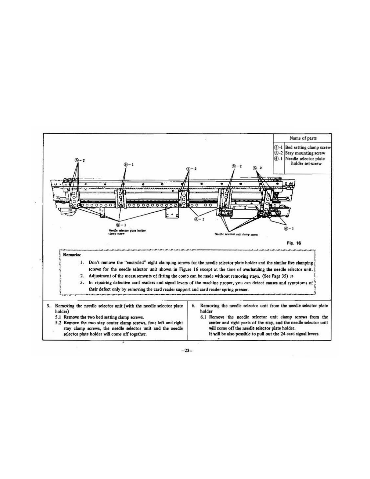
Remuka:
Nam
.e of parts
®
·I
Bed
setting clamp
screw
®
·2
Sr
ay
mounting
scr
ew
®·
I
Needle
sele<:lor
plate
holder
tel-screw
Fit. 11
I.
Don
't
remove
the
"encircled" eight
clamping
screws
for
the
needle
selector plate holder
and
the limllar fl.e
clamping
screws
for
the
needle
selector unit shown in
Figure
16
except
at
the
time
of
overhauling
the
needle selector unit.
2. Adjustment
of
the
meuuremenu
of
fitting the
com
b can be
made
without
removing
stays. (See
Page
35) n
3.
In
repairing defective card readers
and
signal
levers
of
the
machine proper, you
can
detect
causes
and symptoms
of
their defect only by
removing
the
card reader support and
card
reader spring presser.
S.
Remotms the needle selector unit (with the needle selector plate
holder)
S.l
Remo.e the two bed tetting clamp screws.
S.2
Remove
the two stay center
clamp
screws,
four left and right
st1y
clamp
screws
,
the
needle aelector unit and
the
needle
~elector
plate holder
will
come
off
together.
6.
Remcmng
the
needle
lle!ector
unit
from
the
needle selector plate
holder
6.1
Remove
the needle
~elector
uni
t c
lamp
ttrewt from the
center
and riJbt
puts
of
the
my
,
and
the
neeclle
~elector
unit
..W
come
off
the
needle
~elec
tor
plate holder.
It~
be
also
possible
to
puB
out
the
24
card
signalle.e n.
-23-

DISASSEMBLING THE NEEDLE SELECTOR PLATE HOLDER
---
·--
··---·-·--
···-
······---·--------,-
-------!
Signal
lev
er
haoldet
Fig.
17
'#>
UPPER
IDWER
U,
/
Needle seloctor
plate No. 7
..
s
" I
L,
U,
L.
u.
L.
1.1 Remove
two
screws securing the signal lever holder, and
remove the
signal
lever holder,
1.2 Remove eight needle selector plate springs. (Before removing
the
springs, take
note
of
their positions.)
L3
Remove tho E-shaped snap ring (2.5) from
the
needle selector
3
8
6
4
2
Name
of
parts
1----
7
-I
Signal lever holder
clamp
&erew
7
-2
Needle selector plate
7
-3
E-shaped snap ring
(2.5)
Needle selector plate holder
Fi
g.
18
plate shaft (square}
on
the
rear
of
the
needle selector plate
holder, and
remove
the
shaft. ' ·
1.4
WhUe
sliding the eight needle selector places one
by
one
to
the
right, remove them through
slots
in
the needle selector plate
shafts
A~
shafts).
-24-.
l
f.

tay,
right
@-6
Card reader
re&t
ase
cam
®-
6
Snap
rl~~g
9
Cud reed
ing lever
Cudpidepm
@-3
®-
a
holclet Can! f
codln&
k
nob
Intermittent
feeding lever
(i)-
.
Clutch spring
®
-•
Beh
guide
@
-II
Ca
rd
guide
@- 6 ® - 6
Bevel gear
stop
per
pla
te
Card
feeding cam
-25
-
Name
of
parLS
®-I
Need
le selector un
it
clamp screw
®-2
Card
rea
der spting
presser
pta te c
lamp
scr
ew
1
®·3 Spring plate clamp
screw
: @-3 Spring plate
t®4
.Be
lt gui
de
1
®-5
Clutch spring
®
-6
Clutch cam assembly
®
-7
Car
d feeding roller
assembly
<_
8).8
Card
feeding knob
I
nt
ermittent feeding
le
ver
® ·9 Card feeding lever
@-
1 0 Card reader
re
lease
sp
ring
®-
II Card guide clamp
screw

DISASSEMBLING THE NEEDLE SELECTOR UNIT
8.1
RJ.moYe
five
screws
securing the
needle
selector units on the
center
suy
and
right stay,
and
rem
oYe
both st
ays
.
•
When
installing
the
center
lily
and righ
t stay, they must
be
placed correctly in the oriainal
posiliOil$.
Therefore,
it
is
advisable
to
marie
their poli
tl011
1 on both stays with a llotted·
head screwdriver.
8.2
RJ.move
three
screws securing the card reader
apriDJ
presser plate,
and
the card
re.tdor spring preuer plate
a11d
card reader spring can
be removed.
8.3
Remove
two
screws
securing
tho
'Card
reader hold
er
plate,
and
pull
it
out toward you. (Tho card
guide
pin holder .
made
of
plastic· can
also
be
removed
at the
same
time.)
Also
24 card
readm
can
be pulled out.
8.4
Remove
two
screws
(tosether with
washers
) on the belt
guide
plate (right), and pull out the
belt
guide plate to the rigltt.
8
.S
RJ.move
the clutch spring.
8.6
Remove
the
map ring located under the clutch
shift fitt
ed Into
the
clutch
wheel.
Now the wuher, card reader rele
ase
cam,
clutch
wheel (aet) and clutch
cam
A (shaft) c
an
be
removed
. Also
the card feed
cam
beve
l sear stopper plate in the needle selector
u
nl!_can
be
removed.
8
.7 Remove
the
card feeding
roUer.
8.8 Remove the
E-eiip
2 located under
the
card
feed knob,
and
the
card feed !mob abaft can
be
pulled out upward.
Also
the
Inter·
mitten! feeding l
eve
r,
chana<
lever
, intermittent f
eedinJ
l
ever
spring
and
card feed
kn
ob lock cam
c:ao
be
pulled
out
upward
.
8.9
RemoYe
the step
screw
from
the
card
fee
d lever,
and
the card
f
eed lever
can
be
removed.
Also
the
car
d feed adjust
in
g plate can
be
puU
ed out.
8.10
Re
move
the card reader release spring from the
side
of
card
reader re
lease
abaft.
8.11
Remo
ve two
screws
(rigltt and left) securing the card guide. The
card
feed
base
(left)
ca11
be
pulled out to the left, and the rigltt
one can
be
puUed
out to the righL
..
-2
6-

Spring plate
ASSEMBLING
THE
NEEDLE SELECTOR
UNIT
rec.~ma
kno
b stopper
cam~==~===s
~;~~~~
~~==
==~~~
~~~
(i)-5
Ca.r
d
RadtJ
rel
ease cam
@-
3
Cud
feed.i.na
knob
CD
-4
<D·
4
Cud
feedlns lever
1
lntennit~nt
feoclinJ lever
Fig. 21
(!)
Card
feed.i.na
cam
How
to
adjust
the
~tary
cam and C
lut
ch
wheel
(i) P
o*
needle
se*"
'-
nto
the
bact-:·.·
-TT-
(U
PPER
VlEWf
the
cut
pordo.n
clut
cb
wheel
with
top
of
the
roWy
cam
shaft.
,.~
··
Fig.
22
Fig.
23

Card Feed Lever Adjustment
Turn clutch cam A in either direction so that the card feedcam pushes the
card feed lever upward. Then push down the right side of the card feed
lever until the ratchet begins to move, and lock with step screw.
--··
t
1.1
Insert the card suide between the card roller and rotary cam from
the left side, and
insen
the card roller shaft and rotary
cam
into
two
holes in the c
ard
feed base. Then lock the card feed bases,
right and left, with card guide mounting screws.
• Clearance
bet
ween the card roller and card
suide
should equal
the total
tltickness
0.6
mm
of
three punch cards.
}
.2
Insert
the
card rol.ler
unit
into
the
needle selector
unit.
It
is neces·
suy
to
hook
the ratchet
onto
the
card feed
stopp
er plate on the
card feed base (rigth).
Next,
lock
the
card feed bases, right and
left,
to
the rear
of
the needle selector unit by means
of
spring plate
and clamp
screM
temporarily.
1.3
I
I •
1.4
..
1.5
Insert
the
card feed
knob
stopper
cam
into
the needle selector
unit
from underside,
then
ft
.x
the
intermi
ttent
feeding lever, change
lever and sprln&. Insert the card feeding
knob
shaf
t into
the
card
feed kOob stopp
er
cam, intermittent
feeding lever and change lever
. from
top
of
the
needle selector
uint.
Insert the card feed adjusting plate
into
the needle selector unit,
and· secure the c
ard
feed l
mr with
step
screws.
Mako ......
tha~
.
the intermittertt
fee
ding lever should go between
·
the;~
feedJng lever and
round
plate.
(Please refer to Fig.
42
on
page 40.)
Insert
the
card
feed
cam
and bevel gear stopper plate in
to
the
needle selector
unit
frorn
the
right side, and insert the
clutch
wheel
and
clutch
cam A into
the needle selector
unit
from
its
top.
{Aiipl
die
eu
t portion
of
die clutch wheel wlrh
top
or
!he
needle
3dector plate
cam,
aod
polition the needle
~elector
cam
so
that
die
cam lobes
we
on
rhe
other
side and rhe flat portion is in a horizon-
tal
po8itlon.
lbm
mall
the
bevel
JHII. Refer to
the
f'J3U"'
on
die
risJ!t
oft
p•
'l7
.) Next, pass the
clutch
cam
A between the card
feed c
am
lobes, and place
the
card reader return cam from the
bottom
side
of
the needle selector
unit,
and lock with washer and
E-shaped stopper ring 2.5.
1.6 Install the clutch spring.
1
.7
Insert the b
elt
guide plat e (right) into the needle aeclector
unit
from the right side, and lock with scre
ws
(with washera).
I
.8
Install the card reader release spring.
I .9 Install
the
center
stay
and
right
stay
in
the
poslti~
(
anabd
on
the needle selcetor
unit
with
a slotted-bead
scre.,....ll!~
1111\an
disassembled), and secure with screws (
with
washers).
...
..
. -··. . . .
.,
-28-
-·
·-
---

.
ASSEMBLING
THE
NEEDLE SELECTOR
PLATE
HOLDER
_j)
Q
Q
n n
Q ®-t
No. of
.-dle
..
leetor plato
ac=>
•
~
~(:IIQ
c::J: Q
c:::!od
~
c:::>c=
0
c=>
00
olt
Qc::)<::)
c::)<::)t:)t::IC)
c::>C)~Q
C)
c=>
~~~c::::)Qc=r~
QQc:;)t::IQ
0
c:::>
00
olt
UPPER
Noodle oolec
tet
plate No. 1
• 0 0
(:)0
C::::.
c::t
c:::tCI 0
c::t
C)
LOWER
ol3
s
ac=>
~Q~c:§=l'C)~~
o~&:...
oc;;:;,oc
0
c=>
00
u.
I
a
c=>
Q Q
c=
<:::::)
c;::)
c::::l «:::1
c:::t
t::)
<=
C)
0
0
c=>
00
ol•
L.
3
~
·
c::I<:::IOO
C)QOO
Q O
u.
ols
8
"
a(
:::::>
"b=
~c§"~
=c:§'===~
&,
0
c=>
00
L.
6
a .
c=>
CIOC)CIClQQQO
Qc:::>c:::l
0
c=>
0 0
ol6
u.
4
,
c;:)c::t•c::;)QC::.OC)O
CIOt::l
L.
oc=>
coo
•
ooc(J
c::;:,ooc:3'
0
~00
olr
2
c::Jt:)C)c::)c;::)Q
QQC':)
0
_Jl
Q
ll n !l
!l
%Ja
oc=>
Ql:::'""===;=d"~~~~
=<=i.
0
<::::=>
00
•
Si.
· .
Sipl&l le'rer
OJ->:&tion
bolo
Fig. 24
.,
®·
t
Shaf
t B
'
®-·
I Noedle select
or
plate
lhaft A
Needk
oele
ctor plate bolder
truer! needle
!doctor
plato Into
thil
silts
Fig.
25
2.1
Install the needle selector plates on the needle selector plate
holder
in the order
of
7, S, I, 3, 8, 6, 4
and
2.
Align
the
needle selector plates
with the
sU
is of needle selector plate
shafts A (6 pieces), then insert the needle
se
lector plate shafts
B and secure with E«<aped
map
ring .
. -
( .
2.3 H
oole
eight needle selector plate
sprinp
on
sprina hoolcs as
illustnte!labove
Fig
. 26.
Sprlnas
should be hoo
ked
on
to the lower part
of
needle se·
lect
or
plates, S, 3, 6 and 2 and on
to
the
upper of
~die ~elcc-
. .
tor
plate., 7, 1, 8 and
4.
In otber
word&,
!lprinp
ue
posi·
tioned up and down alternately.
~--------~--------------~-----------
---'~
--
---~-----------------------------------------------r~
-29-

3.1
3.2
3.3
3.4
3.5
ASSEMBLING THE NEEDLE .SELECTOR
UNIT
IN THE NEEOLE PLATE HOLDER
®·I
Fig.
28
(~
- I
®-2
®·3
;@·S
!®
-6
I
Name
of
parts
Needle
sel~tor
unit
clainp~
S.lgnal
- holder
clamp screw •
Card reader
Card
reader holder •
Card
reidei'lprin,
Card reader lprina
pres1er plate
\
..
0
·~®-2
\:::::::===~:::=~
SJa!W
lover
holder
i,
-
Carel
TOader
\
Shorter one ... on can!
"'"a!
I
lever side
Fig.
'D
Install
the
neelde aelector unit
in
the needle selector plate
holder, and tighten three needle selector unit clamp screws
of
the center stay and right stay. •
Insert twenty four card
sil!llal
Ieven from
th~
needle selector
plate side, in the order
of
smaller ends. Install the signal lever
holder, and secure with two screws.
Hold the needle selector wtit with the reverse side front, and
insert
2.4
card readers into the needle
sel
ector unit.
Be
sure
to
place
the
card reader
II
011 the right side
of
the rianaJ lever.
Remove. the. screws which war secured temporarily
at
the step
1.2 and temo•e the spring plates.
Fir the card guide
pin
holder (plastic)
to
the card reader holder
3.6
-30-
Lonpr
one
•••
in
needJe
.
~'
uDlt
hole
plate, and insert right and left spring plate$ into the tab
of
the
card roller holder right and left. Then secure wfth two
sae\VS.
Place
the card reader spring
so
that
the card *fader is
posl·
tioned under the center
of the
carf
reader spring, and hold
down the spring with the card reader spring
ho
lder. Then
secure with lhree screws.
Installation position
of
sipallever
holder
Allow
a clearance (0.1 - 0.3
mm)
between signal. lever holder
aJ!d
needle selector plate 2.
Take care so
that
needle aelO!:
tor
plate 2
Is
not
forced
by
slplal
lever holder.

ASSEMBLING
THE
NEEDLE
SELECTOR
PLATE HOLDER IN
THE
BODY
...
Take
measu1e
of
a distance between
the
needle bed lower plate
and
needlf. selec·
tor
pl.\te holder
at
thtee
pl.\ces - buth
ends
and
the centnl
part
of
the
holder·-
by
use of a
slidint
calipers.
pl.\te
holcler
Fig.
29
4J
Set
the
needle selettor unit
to
the
machine
body
and fasten
with four clamp screws for the left, central and right stays
each and
two
clamp screws for
bed
setting
p_late
temporarily
and after making adjustments mentioned below, fasten the
needle selector formally.
FittiD&
of
lhe needle selectOI' plate bolder
Fit the needle selector plate holder according
to
the measurement
made with a Sliding calipers as described
io
Figure
29
_
. ' -
--
-,
. '
Name
of
parts
(!).!
.o~~·Stay
fitting screw
.;:::.:
4
-2
Machine clamp screw
I
:':
•'
,..
--
Fig.
30
Stay
center
Stay
risftt
-31-
Fitting
of
Che
needle
selector uoit
Fit the needle selector unit so that the distance between the uoit
and
the side
of
needle bed reat rail come
to
69 millimeters.
' .

5.
Mounting
the
bell
Name
of
parts
'i'·
-3
""
(!)-!
(!) Connecting
pin
0 0
f
~
Conn<>ctin~
hole ® · I
c 6 6
®·2
PuUey
shaft support
clamp screw •
Concave
part
of
plllloy
®-
5.1· With push
button
_being
kept
dowo,
pus
the
belt
at
once.
Fit
the
belt so
as
to
make
the
conoectins pio face inside.
1. On
the
side
of
the puUey,
pus
the belt from
your
side
by
fittille
the
belt connecting pin
into
the
concave
part
of
the
"puUey.
2.
On the side
of
the clutch wheel,
pasa
the
belt from
your
side
by
fittina
the
belt coJtDeCting hole
into
the
concave
.
..
-32
-
®
-3
Pulley leaf spring
@-1
/ binding
screw
Concave part
of
clutch wheel
]B
jo
IE
Fig.
32
· . part
of
the
clutch wheel
to
connect both ends
of
dii
::
belt with
eacll
other
.
. · .
.
..
5.2 Stretch
the
belt
to
such
an
extent
as there is
no
slack
and
5.3
~g\tten
right and
left
clamping screw for
the
pulley shaft
·support.
Put,.the
!'IJ!Iey spring in the pulley shaft and fasten with the
biiRiiils
screw.

6. Mounting the
machine
body into the
case
7. Mounting the accessories box
8.
Mounting the needle selector panel
Name
of
parts
~
®·s
6.1 Keep the machine body in the case. Left part
Is
first.
6.2
Tighten two right clarnpina screws and the equal number
of
left clamping screw for the needle bed.
6.3 Put
th
e right
and
left leaf springs in position
of
the needle bed
upper
plate
and
fasten with needle
bed
upper plate clamping
sc
rews.
6.4 Tighten thr
ee
clamping screws for the ease reinforcing plate
A
and cax
reinforcing plate B.
6.5
Fit
th
e right
and
left machine body
fi
tting plates
onto
the
back side
of
the case with two clamping screws for right and
left
fit
tfn,
plates each.
-33-
®·2
® Lo
'VIIC-
r C
ite
Fig.
33
Needle bed clamping
screw
Need
le
bed upper
plate clamping
SCJ
CW
Case
reinforcing
pla
te
clamping screw
Machine body fitting
pl
ate clamping screw
Accessories
bo
x
clamping screw
Direction indicator
Needle
selector panel
clamping
SCJ
ew
Card
stop lever knob
7
.I
Keep
the accessories box
at
th
e left si
de
of the machioe
body and
fasten with clamping
screw~
.
8.1
lnselt the direction indicator (plas!ic-made) into the clutch
wheel shaft.
8.2 Keep
th
e needle selector panel
at
the right side
of
the machine
body
and fasten with shree needle sele
ctor
panel clamping
screws.
8.3 Insert the cu d stop lever linob into the lever.

INSPECTION OF NEEDLE SELECT
OR
FUNCTIONS
Function Standards How
to
check
-··
Han
d·operated card
feed·
I.
That
if
the card feed knob
is
pushed down , then
I.
Make
sure by pushing down the card feed knob.
ing the
gear
will
be
engaged.
2. That when the card feed kn
ob
is
p~ed
down, 2.
Malee
sure
at
the
same time that you make sure
of
ca.rd
readen come
off
completely from cards
and
(I).
the rotacy cam.
3.
That the card feed knob turns
moothly.
3. lnaert tho card
and~«
if
it
Is
feedcd.
4.
That
click stop
of the card roller sha
ft
functions 4.
Mak
e sure
at
the
Arne
time that
you
make sure
accurately.
of(3).
'
Automatic card feeding & I. That card readers come
off completely from
the
I.
Make
sure
of
(I)-
(4)
by
turning
the
clutch wheel
clutch
function
at
a time
card
roller and rotll}' cam.
:
by hand. (Tactile impression and
visual
obterva·
when
roution
ciirKtion
of
lion.)
clutch wheel
is change
d.
2. Th
at the feed
of
card roller
by
meant
of
the
.
Jatdtet is made accurately.
'..
~
3.
That
after the above-mention
ed
actions, the clutch
wheel gets
into free rotation.
4. That the clutch
wheel rums smoothly.
Switching
of
card
stop
I.
That the card stop lover can
be
switched smoothJy.
I.
Make sure by
awitching tho card stop lover by
lev
er
hand.
Engaging
of
clutch wheel
I.
That the clutch wheel and rotary cam are engaged I. Vlsual observation.
and
rotacy cam
with each other in a corre
ct
pocltion.
.•
..
-3
4-

1.
Kilbt
and Jert rabric
gauges
1ft
uneven; len
gth
of
knitted
fabric differs
at
both
ends
HOW
TO ADJUST THE MACHINE
BODY
I.
f itting
measumnents
of
right and left combs ate uneven.
(How
to
make fitting measurements of combs
for
Models KH-830)
r
113.~
~
~
11
.!!
1 ,
c:1
. '
-·
'.
•
I J : l
•
'
I
..
..
'
'
1 I
.1
0
~jl}
"bb
'l
11
I.
Take
out
the
machine
body
from the
c"ise.
(See page
21)
2.
Loosen 8 clamping screws for needle bed comb on
the
stay
right, center and left and lower holder plate. (See
on
page
23)
3. Loosen 12 clamping nuts on the back side
of
combs
with a
wrench.
I
4.
Put
out
three needles each
at
both
ends and in the central part
of
the nee
dle bed
and
determine a position
of
cOmbs
so
as
to
0
~
let
needles
come
to
midway between
both
combs. {Bilateral
ill
~
adjustment)
5.
Set
fitting measurement
of
combs
at
I 13.2 millimeters
at
both
ends
and
in
the central
part
of
the machine
body
and
fasten
with
clamping
nuts
. (Longitudial adjustment)
(In
this case, keep
it
in mind
that
if
such nuts are tightened
too
(Reference)
How
to
make fitting measurement
of
combs
in the case
of
old
models
of
lcnhtel"l.
I.
10t.310/"'
L
~
It
CbdJ
....
....,
Fig.
35
-35
-
,
.....
6.
7.
"'
Fig.
34
ha
rd, screwt will be twisted
off.)
(Adjust measurement
of
fitting combs
by
use
of
a sliding call·
pers
and fasten with clamping nuts.)
Make fitting measurement
of
combs for
old
models
of
knitters
in such
a
way
as
shown in Figure 35.
After malcing such adjustments,
don't
fail
to
knit
30
rows
in
plain s
tit
ch
with
the
stitch ad
jus
ting
dial set
on
"5", 200stitches
and
by
using medium
yam
and
then
measure the length
of
fabric
at
the
78th
stitch each from center.
Make sure
that
a
difference in length between right and
left
measumnents
is
len
than
three millimeters. (Apply a
load
of
1 Idiogram,
on
the
average,
to
fabric.
For
the
1
kg
load
is suitable the use
of
about
four claw weights on
the
east-on
comb
long.)
Model
KH-31 J(KH.S
51
KH-S61/KH·S71
KH-580
KH-585/JCH-588
800
KH-8
20/810
, .
. ,
fitting
measurement
of
comb
107.5
mm
106.5m
m
106.8mm
108.3
mm
11
4.3
mm

2. Needla come to
move
li&h
tly
in
part
I.
Needle
retaining spring
is
broken
Not<llepr
....
r
Remmna
tbe needle
rebiDinJ
1priDg
I.
Tab
out the machlne body
from
the
case
(See
Page
21
).
2. Pull out
tho
sponge
bar.
3.
Pia
U out the needle presser.
4.
Bring
foiWird
the
plain
needlea
to E-posltlon.
5.
Re
mov. thr
ee
bindins
acrews
for the nee
dle
retaining spring on
the comb
and the nee
dle
retaining spring will come o
ff.
6. Remov. the needle retaining spring
from
the comb, and
puU
out the spring.
•
-36-
Fig.
36
Fitting the
needle
ret.inin aprinJ
I . Fit the needle retaining spring onto the comb and
fu
ton
the
ne
edle
retaining spring
on
comb with three bin
ding
screws
for
th
e needle retaining spring.
2. B
ring
back the nee
dles
to
B·pocition.
3.
Put the needle presser.
4.
Plat
the
sponge
bar.
5.
Keep
the
machine
body
in
the
case.
(See
Page
33)

3. Needle ldection
is
not
conec:l
(C.Ual)
. Moue ling
of
Timing belt, Clutch wheel and pulley
Is
not correct.
Fig.
37
The connecting
part
of
timing belt must fit both conca
ve
parts
of
.i pulley and clutch wheel.
'i
(See on
paae
32
to adjsut.)
s
,
(Caua 2)
M
ount
ing
of
rotary cam
or
clutch wheel is not correct.
The
carriage movement
is
SYnchronized
with the needle selection
mechanism with
timing belt. Therefore,
if
there
is
a time lag,
It
c
auses
wron&
needle
selection.
(Correct position
of
rotii)'
am
and clutch wheel)
telector
cam
to
side.
(Cbeclc
the pOiition)
(Upper
riew)
the
CODC&ft
patt
of
the
clutdlwbulju11
"""'the
rofaly
cam shaft.
Fig.
38
When
the flat part
of
r<?.JII!¥
cam
is
placed horizontally, the concave
part
of
clutch wheel muit be just over the rotii)'
earn
shaft.
2.1 Remove the timing belt 1nd belt sulde plate
of
the clutch
wheel. ·
2.2
Rem<We
the
map
rln&
for clutch
wheel
shaft from back side
and
~emove
the car4;
fee4ing
cam and card reader
release
cam.
2.3 Pull up the clutch wheel a little, and turn the clutch wheel to
get correct
p<)8itlon.
· ·
-37
-
' .

(Caute3)
Mounting
of
card read
er
guide
plate is not correct.
Position
of
rotary
cam
is
not correct.
0
0
0
0
o·
0
0
0
0
'
0
0
0
'
g!
..
0
0
0
"'
<CJ
I
·~
·
.,.
!
0 0
..
0
or
..
0
0
0
0~
.~.
-
..
..
0
ov
Fig. 1
~
~
. ;'..
...
..
3
.1
Make the punch card for
checking
as illustrated .
0
~
it
I
~
.
-
38-

.
'
...
.~
Fig. 2
3.2 Insert the
che
c~punch
card
and
stt
the starting line. Confirm that
all
c:ard
readers are not in contact
With
any position
of
rotary
cam.
~·
-39
-

Loosen 3 screws
Fig
. 3
1
1il
3.3
LooS<!n
two
screws
for rotary
cam
adjusting
collar
and one for
card
reader
guide
stoppe
r.
NOTE:
Do
not take off
screws.
0
-
.. ·
'"11.
~·:~
:
·
·~

·'
caN
JOOder
..,Jdt plate
Cardmd
er
3.
4
By
mo•loa the
cud
reader guide stopper, movr
the card reader guide plate to
left hand side until
the card readers softly touch the riaht side
of
the
card reader
guide
window as sho
wn
in
the
filure.
Then futen
the
screw.
COld
JOider
,Wde
SlOf>per
-4
1-

;
'6'
..
0
-
I
3.5
Pusl>
down the card feedins knob
to
make the card leaders
doWll
, then releate
it.
The
cud
readers must Coot41 up by sprins
pressure.
If the card teader does
not
come
up
by
sp
ring pressure, repeat item 3.4.
-42-
•.
.
.,.; ..
:;
'
Fi
..
5
.,
,
'

,.
Fig
. 6
;;
j 3.6
feed
the punch card as sho
wn
in the figu
re. (O
ne
piece of card reader c
omes
up.)
;J
~
-
-43-

After adj.,.ting, please check the needle selection,
if
the problems still appear, please check the
oth
er
part
of
the needle selection mechanlt.m.
Fig. 7
3.7 Turn the rotary cam
so
as
to let
the card reader
in
working position,
and
forcefully push the rota
ry
cam to left until the card reader
touch the left side
of
the card reader guide window, then lighten the two screws for the rotary cam adjusting collar securely.
In this case, rotary cam adjusting collar must keep in touch with rotary cam holder plate.
!
. ~ ..
: ..

(Callie
4)
Mounting
of
needle selector unit
ll
not
com>et.
/ wtrik
....,.
l
~~,.,.
•"'""""
l'tl
lhc
J
4
iJI•rat.~tM
..
ol-*~
IUf Uf
•ttd
.....
WI«1
0f
VII
i~
~~
.,
nl
•
4.1 Take the needle bed out
of
the case. (See
on
page 22)
4.2
LoosenS clamping screws for stay center.
(3
Loo~n
9 clamping screws for stay right.
4.4 Adjust the
po~ition
of
the needle selector unit
by
refering the
instruction
on
page 31.
fg
4:5 After adjusting, fasten the screws.
:
;s'
..
g
(CauseS)
Punch
card is
not
fed cortectly.
Card
CJampiilg
II<UW
Card
feodina
knob
for
catd
feed
adjosr.or
plate
5
.I
Take
the
needle bed
out
of
the case.
..
..
. ..
~
.·
Fig. 41
5.2 Turn the belt and
stop
it
at
a stage where the card feed lever is
raised uppermost.
5
.3
Looseo
the
clamping screw for card feed adjuster plate.
5.4
PUsh
down the left side
of
the card feed lever and sotp
the
card feed lever when tbe latchet feed is applied, then tighten
the clamping
screw for the card feed adjuster plate.
5.5 Loosen two clamping screws for the latchet stopper and push
up the latchet to the full until a small gap
(0.2-0.5
m{m)
is
made between
the
tip
of
the latchet stopper, then tighten the
two clamping screws.
CONFIRMATION
I
Make
sure:
1
(I)
Tha
t when the latchet is pushed
up
to
the full, the card won't
'
be
fed
at
a pitch even
if
the latch
et
wheel is turned
by
hand.
(2)
That when the card is inserted and .then
the
carriage (Chan
ge
knob is set
on
KC.)
is
moved to.;.iaJ!i and left, the card
is
fed
at
a pitch accurately.
~~.~·
.

I
'- -
..--~---olf!'-
_.
----
--
--------r--
---
------
--
-------,
~
·
• ( ,
• <
'•
1
~
(C.oue6)
When
the
card
Jock
le¥tt
i! switched from the intennittent position
to
regular feeding position,
the
pun
ch c
ud
is
not fed b
ecause
of the
intermittent feed le¥tr
does
not
work smoothly .
.,
..-
·------------
:
Shoul4 wotk •moothly
Make
the
clearance
between
the
lntermltteot feed rever and needle
~
aele
ctor unit body
so
u
to
make
th
e lntermitti!nt
~
lever freely.
I
· ··~
.
·.:
.: .
• •
:>.
{Cautc
7)
The needle
is
bent.
(How
to
adjust)
Replace tho needle.
Opentlon
of
c:hanp
lenr
llhould
be
IJ&IIt
Fl;.
42

I. Stitch
drops
Cause
'
I.
Wrong bilateral position
of
the
leaf spring
Fit-
42
2. Wrong vertical position
of
the
leaf spring
Flg.43
3. Wrong position
of
the feed hook
liij@
!Wll
Amounta
of
feed• Amounts
of
feecb
pt
llrpr
aet
arna.Uer
Fig.
44
HOW
TO ADJUST L CARRIAGE
·.
~
·,
: .
..
..
~·
...
:
~
..
Fl~
46
- 47-
How
to
adjsut
I .I Remove l Carria
ge
cover and
loo
sen right and left clamp-
ing
nut
s for the le
af
spring.
1.2
By
referring to f igure 42, place the leaf spring
at
a distance
of
0.
5-1
millimeter inward from the cross section
of
the
pia~
earn
B on· the basis of the plate cam 8 and fasten
with
cl
amping
scr
ews
.
2.1
By
referring
to figure 43,
adjsu~t
the
tip
of
the leaf spoing
so
as
to
be
bigbtened
to
the
same
level
as
that
of
the plate
cam
B.
2.2 Although you may
use
a pincers or pliell in making such
..
ad
justments,
be
careful
not
to cause
:such
tools
to
~r
ook
the
leaf spring locally .
3.1
•
The feed hook is
fixed
with the feed
hook
clamping screw
on
the side
of
the sin ker plate.
3.2 L
oo.en
the feed
hoo
k clamping.
scnw
and move it inward
and
,;.
ounts of feeds
wUI get smaller
but
move it outward
aqp
amounts
of
feeds
will
ge
l larger.
33
By referring
to FigU
re
4S
, adjust the feed
hook
so
as
to
let
a
pp
made in a moment the crossed two latch needles
come
off from
the feed hook come below
0.2-lmlllim
eter.
' t
..
•

Cause
-
---
-
--
-
---
-
--
·-··-· .
4. When L carri
age
sinker plate
is
crooked.
·-----=It'
Tho-
of-
an4
mw.
pia,.
must
be
n,.t
In
llcbt
-1a<t
.nth
-"
·-·
S.
When
main
cam
is
replaced
Fig.48
Fig.47_1.
..
-48-
How
to
adjsut
4.1 ObseNe
the
sinker plate sideward and
se
e
if
it
Is
etooked.
4.2 After connrming it by
visual obseNation, put L
Carriage
into
the
needle bed and poll
out
latch needles
to
the posl·
lion
0,
then
inspect a
gap
between the sinker plato and
the s
tem of
latch needles.
When
latch needles a
re
found
raised
by
the linker plate
(or
there is a wide
pp),
judae
!hit the sinker plate
is
crooked and adjust lhe "crooked"
section.
5 .I
Rem
ove rfsht and left clamping screws for lhe L
Carriage
cover and take
off
lhe cover.
5.2
Remo
ve
three clamping screws for main cam.
5.3 From the
ba
ck
side
of
the L Curiage rear foot, measure
by
use
of a slidln&
~ipers
to place main cam·io such a
way
u
shown in Figure 47 and
fa.sten
with thtee clamping
OICI'ews
.

KNIT·LEAOER KL-116
..
~
...
'
I.
Inclining
the
sheet.
The sheet feeding
gear shaft
is
inclined.
COMBINATIONS
OF KN
ITTE
RS
AND
KNIT-LEADERS
~®By
movin&
the sheet
button
up
·- .
-
~~
p
KL-113
KIA
I$
KL
·116 or down
to
adjust
the
position.
~
I
~
KH
0
-
..
[j] u
•
L•
0
I~-,
~
<D
Loosen
two
screws.
SW!d
-
tt
r-~--'
i
406216001
I
poe.
Seltizla
pla16
~
48
6306001 2
peL
KH·I IO
Yes
a.re
requ.!Jod
odd.i·
Samo11
KL
·l U
tiooally.
•
Se
t
the
row
counter
l
tripper
at
resting
I
p<>llllon
to
oporat6.
·-
Feed
conncetoJ
1.1
Loosen two clamping screws.
'
40S883001 I
pee.
1.2 By moving the sheet
button
up
or
down, adjust the incline
Settlnt plato
486
306001 2
pes.
of
the
sheet feeding gear shaft. Theo, fasten the searews.
Kll-588
Yes
Stand
Sarno
as
KL·IIS
(lnsert
the
sheet
into
the
Knit-leader, and check.)
406
216001 I pee.
-
are
requ.!Jod
ocldi·
~
"'
:s
tionally.
..
0
f--
·
-.
:t
' '
KH-800
Yes
lmpoul
ble
Imp<>Oiiblo
0
::
Settlnt plato
KH-8
20
'
486
30$001 2
pCL
Ye
s,
(but colow js
Yes
KH-8
30
are
requ.!Jod
lddi·
not
mat
ch)
i
tionaDY
.
-49-

RIBBING ATTACHMENT KR- 830
• Wh•n you
att
ach
the
ribber
to
the
lcni
tter model KH-820
or
KH
-830,
you
can attach
the
ribber without any adjustment.
but
if
it
is
nec:eswy, pleue follow this
IJWiual
.
•
There
are
th.ru adjusting positions,
and
once
you
do these adjust-
ments,
you
are
not
required
to ad)UJ
t when
you
reattach the
ribber.
I. Meet
ins
of
needles
on
both
beda.
The plain needles and purl needles are directly opposite
to
each
other. If
not,
adjust the position.
1.1
Set
the half
pitch lever
on
P.
1
.2
Set
the
racldng
indicator
on No.5.
1
.3
Loosen
two scr
eM
(-)
which are
beside
the
mark D
on the
left
end
of
the
KR
needle bed .
1.
4 By turning
th
e grip handle, adjust to get
the
proper position
(ICK
and
KR
needles meet) u shown in the
figu
re.
1.5
Mter
adjusting. fasten
two
screws tightly.
~
,,,,
l
//
::
~v
·I
·
,...
two_..,/ r
•!'a'-~
!
0
Fi8.
49
I
l
)
'
-SO-
2.
He!lht
or
n'bber bed.
Set
the
half
pitch lever on H,
and
bring fo.,..trd 10
•ach
needles
on
both
enc!J
of
KH needle bed.
O!eck
the
clelll'Ulce bet'llleen
the
back
of
the
KH
needle and gate
pegs
of
KR
bed.
J.l
-
I.
7
m/m
is
conect.
2.
1 By pushing
down
the
levers
on
both
bracket, let down
the
ri
bber one step. At
the
back
of
the
ribber, y
ou
will find
out
the nuts. Looeen these
nuts
by
the
spanner. Then, return
the
ribber
to
original position.
2.2 By moving
both
height adjusters up
or
down, obtain
the
pro-
per
help.t
(
1.1 -1.
7 m/m).
Mter
1djusting, let down the ribber-one step, and fMten
the
nuts by the spanner.
Theo
lift
up
the
ribber to normal
pooi
·
lion
.
Loosen Tiahte.n
•Up
I
0o'11'11

3.
Distance
between two
bed
a.
Loosen the clamps for reinforcing
arm.
Bring
forward
10
each needles
on
both ends
of
KR
needle
bed.
Oleck the distance between the back
of
the
KR
needle and
KH
gate
pep
.
0 - 0.6 m/m is
com
et.
3.1
Looaen
both thumb screws by the spanner.
3.2
To
obt
alJI
the proper distance
(0
- 0.6 m/m), adjust by
tum
·
ing
the bolts on both sidea
of
bracket
by
the
spannu.
Turning
to
the
left .....
..
clo~e
Turning
to
the rigbt ...•..• aeparate
3.3 After adjusting,
go
back the
deedlu
to
A pCiitlon
and fas
ten
both thumb
screws.
3.4
Futen
the
clamps
for reinforcing ann.
Fi
g.
51
The
oth
er models
In
case
of
attaching KR-810 to KH-820.
Height
....... The clearance between the back
of
the
KH
needle and
gate peJ$
of
KR
bed
is
0 • 0.6 m(m.
Distance
·- ··- The distance between the back
of
the
KR
needle
an
d
KH
gate
pegs
js
0-0
.6 m(
m.
In
case
of
attaching KR-810 to KH-830.
Height ·····
··
The clearance between
the
back
of
the
KH
needle and
gate
pep
of
KR
bed
is
1.1 - 1.7 mfm.
-Sl-
Distance The distance between the back of
the
KR
needle
and
KH
r,ate pegs is 0 - 0.6 m(m.

COMBINATIO
NS
OF
KNITT
ERS
AND RI
BBERS
~
KR-
110
KR
-586
KR-587
KR-810
KR-830
KH
-110
Ye
s
Impossible
Impossible Impossib
le
--
lmpoaible
®
Possible
to opera
te
but ®Possible
to operate but
KH-588
Impossible
Yes
impos.silbe
to att.
ach
the
impoosible
to attach the
Impossible
Extension
ralls
Extension
rails
CD
·j;;;j,osill,
ie
but
change
Yes
KH-800
Im
possible
to
p<mible
by repl
acing
Yes
lmpoulble
so
me
parts
KH-820 Impossible
lm
poai
b~
Impossible
Yes Yes
KH-830
Impossible lmpoasible
'
I
I
mpossible
@Possible but adjustment
is
required
Yes
<D
®
®
(!
")
KH-800/KR-586
KH
-58
8/KR
-587
KH-588/KR~IO
JCH
-830/KR-810
Bracket, R
Possible
to attach the
Possible
to atta
ch
the
See
on
page
so-
s 1
407005
001
1 pee.
Ex
tension ralls by
ro-
Ex
tcm
sion nu1s
by re-
Bracket, L
placing the
following
plac
ing
the following
407009001
I pee.
parts. parts.
Thumb screw
Bracket, R
408777001 2
pes.
486223001
I pee.
Bracke
t, R
Reinforcing
clamp
Bracket, L 486223001 I pee.
406791001 2
pes
.
48622
4001 I pee
.
Bracket, L
Screw
486224001
I pee.
405998001
2
pes.
Screw
Table clamp 405998001 2
pes.
405503001 2
pes.
Reinforcing clamp
405501001 2
pes.
-
52-

Mounting demensions
of
each
part
of
KR-830
------··
------------l
•c
onnecting ann
•Set the connecting
arm
to the
KH-~aniage
and
check.
·
Mounting
demension
of yam feeder·-·········123.6 m/m
Demension
between the latch
presser
plate and the
rear
foot of
KH
carriage
.
·4
(For
KR-810·········-124
.2 m/m)
·
Mounting
demension
of
magnet
box·········l4l.S m/m
Demension
between
the
magnet
box
and
the
rear foot
of
KH
carriage
.
(Please
check
when
the latch or hook of the
needle
hits the yarn
feeder
or
magJlet
holder.)
'""'
IE----1%1.
6'1.---
~-
------141.5
...
--
°KR
carri.age
·Mounting
demension
of sub
raising
cam
..........
J4.S
m{m
Demension
between
the sub
raising
cam
and
the
rear
foot of
KR
carriage.
·
Mounting
demension
of
rub
slitch
cam
.......... st.3 m/m
Demension
between
the sub ·stitch
cam
and
the
rear
foot of
KR
carriage.
(Please
check
when
the
KR
carrlager-------+--
does
not
slide
on
the
needle
bed
smoothly.)
St.3'Mo
14.5"
•Needle
gate
pegs
-
Mounting
demension
of
needle
gate
pegs
.......... J20.4 m/m
(For
KR-81Q
.......... tQ3.S m/m)
Dt.m
enslon between lhe needle
pte
pegs and the
rur
rail
of
the needle
bed.
Fig.
54
-53-

HOW
TO ADJUST THE COLOUR CHANGER
(Troubl
e)
I.
The
yam
does not get
into
the
yam
feeder
or
the
separation plate
can
not
catch
any
yam,
though
the
changer
button
is depressed.
2.
The
yam
gets
into
the
yam
feeder
or
the separation plate catches
the
yam, tho
ugh
the changer
button
is
not
depreaed.
(How
to
adjust)
I. Colour cllanaer
KHC
·820
1.1
Pos
ition
adjustment
look
at the colour changer from side and
cheek
if
th
ere
is
a
separstion plate just
in the center between
the yam
guide
of
chan
ger
button dep
ressed
and
not
depressed.
(&e
Fig.
55
)
Not deptosstd
button
roller
Si.nbr
pltle
for KHC
-820
1.2 Height adjustment
4 Sh
ou
ld
be
.....
,
~'-li~
---
Oepresie:4 button.
rolln
====-
>.;..
---S
epanlion plate
(S
icl
e view)
Chanprum
Fig. 55
When the
chm
ger
ann
is
bent
or
dropped, please check
the
foUowiog dernensions.
u.
n;
I
<.---tt
.....
Extension line
or
tho
boos.
Fio.
56
•,
l . Colour ehanaer KRC-830
2.1
Position adju
stment
2.1.1 Place the connected carri
age
at
the left end
of
the needle
bed.
Depress
the
No. 4 changer
butto
n, and move
the
canla
ge
to
right slowly until the separati
on
plate separates the yarns
com
pletely.
2.1
.2
loo
k at the colour changer from
side
and check
If there is
a separation plate just
in
the middle belwl:en
the
knitting
yam
and
resting y•
ms
. (
See
Fig.
57)
lf not, loosen
the
right screw
at
the
back
of
chanser ann, and
move the changer forw
ard&
or
backward&
to
set
the
proper
position.
Center
.
Knitlin•
yom
• (Back
$1de
)
•
ResDn&
yam
a...,..
r
Ch
..,..rann
I
looseD
thiJ
tcftW
Fig.
57
2.2 Height adjustm
ent
The
top
of
the
connecting adjuster plate
must
be 2
m/m
heigher
than
the
signal
lev
er.
'
Fig.
58
-5
4-

TROUBLE SHOOTI
NG
Trouble
Ca
use
Remedy Note
Caniaae:
Does not move easily. 1. Carri
age
cam sliding part
is out
1.
Oil
needle
butt
and stitch cam. See Instructi
on
manual.
of
oil.
2.
Needle bed
sli
ding part is
out
of
2.
Oil
front and rear rails
of
body and
oil.
carriage.
3.
Sinker plate is in contact with 3. Adjust sinker plate position. See Instruction manual.
gate pegs.
4.
Gauge is
too
tight . 4. Loosen knitting
gauge
.
Needle Sel
ectOI'
:
The same needle does
not
1. Needle
is
bent.
1 . Replace
the
needle. See Instruction manual.
come
out.
2. Needle and rotary cam are
not
2.
Adjust r
ota
ry
cam position .
:
in
the ri
ght
relative position.
'
UnneceSsary neelde sticks
I
I.
Oil
has g
ot
between Medle
I.
Wipe
off
the oil.
out
in eighth cycle.
selector
pl
ates.
'
2. Squeezed between signal lever 2. Replace needle selector unit.
presser and
card reader
guide,
I
card signal lever does
not
move
easil
y.
3.
Signal lever presser holds needle
3. Adjust
signal lever presser position.
sele
cto
r plate.
4.
Ne
edle is bent or broken. 4. Replace needle.
See
Instruction manual.
5. Needle selector plate spring
are
S.
Correct the
hook
of
spring.
engaging with each other.
-
55-

Trouble.
Cause
Remedy Note
Unnecessary needles stick
I.
Too much vertical carriage play.
I.
Replace front
or
rear legs
of
carriage.
out irregularly.
(Fr
ont
or rear legs
of
carriage have
worn)
Abnormal
if
difference exceeds
0.5
mm.
2. The holes
on
the needle bed lower 2. Replace needle bed.
plate has
worn.
Particular needles come
I . Oil has got between needle selec- J.
Wipe
off
the
oil.
out
from 8 postilion to
tor plates.
D position.
2. Bent needle.
2.
Replace the needle.
See Instruction manual.
3.
Too much vertical carriage play. 3. Replace front or rear legs
of
carriage.
4.
The holes
on
the
needle bed lower
4. Replace needle bed.
plate
has worn.
No needle
selection
in
!
I . Poorly adjusted card feed.
1 . Adjust card feed
l~er.
24th
cycle.
I
(Card hole and card reader are
not
!
in position.)
2.
Card reader holder plate has got 2. Adjust
the
gap
to
the
normal level
out
of
position, reducing
the
gap
of0.6mm.
between card
roUer
and
caid
guide.
3.
Card reader fails
to
make regular
3.
Replace needle selector unit.
vertical motion.
4.
Poor adjustment
of
card reader
4.
Adjust card reader guide position.
pi
de.
5. Poor adjustment
of
rotary cam
5. Adjust needle selector plate position.
(Needs a
Uttle shift
to
left).
Insufficient travel
of
needle selec.
tor
plate.
-56-

Trouble
Cause
Remedy
!
Note
No
needle selection
in
1.
Bent needle. I . Replace the needle.
See
Instruction manual.
eiJhth
cycle.
2.
The h
oles
on
the needle bed 2. Replace needle bed.
.
I
lower
plate
has
worn and
become
larger.
No
needle
sel
ection
be-
I. Carri
age
connection claw
does
I.
Adjust relative position
of
clutch
tween needles
Nos. 90
not catch belt at carriage direc- and belt.
-100
at
carriage
direction lion
gate
.
gate
.
I
2.
Change
knob
is
not set correctly. 2. Set the
change
knob correctly.
L
carria&e
Loclu in midway.
I.
Too
fmc
puge
. 1.
Widen
gauge.
See
Instruction manual.
2. L
carri
age
wa..
not kept
down
. 2. Operate L carri.qe in the right
way
.
.
Drop
stitches. I. Poor latch needle
open~tlo
n.
I . Replace needle.
See
lns~~:~~Ction
manual.
2. Bent comb.
2.
Adjust comb teetlt.
3. Feed ltoo
lc
is out
of
position. 3. A
djU5t
both right and left
feed
hook
4.
Cam
is
out
of
position.
position.
5.
Leahprlng
is
out
of
position. 4. Adjust cam position.
6. Separation
cam
does
not work
S.
Ad
just leaf spring position.
prope,rly.
6. Replace Separation cam.
7.
The
L<-arriage
is turned back 7. Take care operation.
before
passing
the last needle.
Comb
teeth catclt stitcltes.
I.
Too loose
gauge
. 1. Make
gauge fmer.
See
Instruction manual.
2.
Ya
rn
catches. 2.
Make
yam
move
smoothly.
3. Too
r
..
t operation. 3. Operate L carriase slowly.
4.
Ben
t co
mb
teeth. 4. Correct comb teeth.
-51
-

•
~
Tr
oub
le Cause
Remedy Note
~i
t
ling:
'
Floating stitches.
I.
Too much g
ap bet
ween sinker 1. Adjust
comb tee
th posiCi
on.
i
S
tit
ches get tudced. plate and comb teelh.
i
-
~
:;
2. Poor
operation
e>f
needle.
2.
Replace needle.
<
3. Too fine gauge. 3. Widen gauge. See Instruction man
u.al
.
i
I
Lateral stripe is produced
I.
Stitch cam differs
in
leng
lh
I.
Ma
ke
adjustme
nt
w
ith
th
e
st
itch
every
second row. between right and lef
t.
adjuster plate.
.
..
Lateral stripe
Is
produced
I.
Carriage operati
ng
speed variation. I . Operate carriage
at
constant speed.
See Instruction manual.
here and there; not 2.
Poor yarn supply.
2.
Lessen tension spring tension.
stitched neatly.
'
r
! Right
and
left
knitted
;
I.
Comb teeth installed differently. 1. Instal right
and
left
comb
t
eeth
I
'
differently.
!
in the same way.
'
Carriage sticks in Midway.
;
!
I . Needle bed is damaged.
I.
Repair needle bed.
See
InstJuction manua
l.
I
2. Needle bu
tt
is damage
d.
2. Replace needle .
'
3. Guide c
am
A
is
installed wrongly. 3. Adju
st guide cam posi
tio
n.
I
I
I
'
!
'
'
!
-58-
 Loading...