

Inkjet MFC
SERVICE MANUAL
MODEL: MFC5890CN
MFC5895CW
August 2010
SM-FAX097
8CAH17(4)
Read this manual thoroughly before maintenance work.
Keep this manual in a convenient place for quick and easy reference at all times.
Confidential

© Copyright Brother 2010
All rights reserved.
No part of this publication may be reproduced in any
form or by any means without permission in writing
from the publisher.
Specifications are subject to change without notice.
Trademarks
The Brother logo is a registered trademark of Brother Industries, Ltd.
Brother is a registered trademark of Brother Industries, Ltd.
Multi-Function Link is a registered trademark of Brother International Corporation.
Windows Vista is ei ther a re gistered trademark or a trade mar k of M ic ros oft Co rp orati on i n t he Un ite d
States and other countries. Microso ft, Windows and Windows Server are reg istered trademarks of
Microsoft Corporation in the United States and/or other countries.
Macintosh and TrueType are registered trademarks of Apple Inc.
Nuance, the Nuance logo, PaperPort and ScanSoft are trademarks or registered trademarks of
Nuance Communications, Inc. or its affiliates in the United States and/or other countries.
Presto! PageManager is a registered trademark of NewSoft Technology Corporation.
Microdrive is a trademark of International Business Machines Corporation.
CompactFlash is a registered trademark of SanDisk Corporation.
Memory Stick is a registered trademark of Sony Corporation.
SanDisk is a licensee of the SD and miniSD trademarks.
xD-Picture Card is a trademark of Fujifilm Co. Ltd., Toshiba Corporation and Olympus Optical Co. Ltd.
PictBridge is a trademark.
Memory Stick Pro, Memory Stick Pro Duo, Memory Stick Duo and MagicGate are trademarks of Sony
Corporation.
BROADCOM, SecureEasySetup and the SecureEasySetup logo are trademarks or registered
trademarks of Broadcom Corporation in the United States and/or other countries.
AOSS is a trademark of Buffalo Inc.
Wi-Fi, WPA and WP A 2 are r e gis ter ed trade mar k s and Wi -Fi P ro tec ted Se tup i s a tr ad ema rk of Wi-Fi
Alliance.
FaceFilter Studio is a trademark of Reallusion, Inc.
Each company who se softw are title is mentione d in thi s manual has a S oftware Lic ense Agreeme nt
specific to its proprietary programs.
All other brand and product names mentioned in this manual are trademarks or registered
trademarks of their respective companies.
Confidential

Preface
This Service Manual is intended for use by service personnel and details the specifications,
construction, theory of operation, and maintenance for the Brother machines noted on the front
cover. It includes information required for troubleshooting and service--disassembly,
reassembly, and lubrication--so that service personnel will be able to understand equipment
function, repair the equipment in a timely manner and order spare parts as necessary.
To perform appropriate maintenance so that the machine is always in the best possible
condition for the customer, service personnel must adequately understand and apply this
manual.
The table below shows the functional comparison between the models covered by this manual.
Model MFC5890CN MFC5895CW
RAM 64 MB 64 MB
LCD (with backlight) 3.3-inch wide color 3.3-inch wide c olor
T o uc h pa nel --- --Wired LAN √√
Wireless LAN (WLAN PCB) --- √
PhotoCapture Center √√
PictBridge/USB flash memory drive √√
Movable platen --- --Slide tray --- --ADF √√
High-yield ink car tr i dg e sensor --- --Ink cartridge detection sensors √√
Ink empty sensors √√
Handset (Hook switch PCB) --- --Duplex printing --- --Backup battery √√
This manual describes the models and their versions destined for major countries. The specifications and
functions are subject to change depending upon each dest ination.
i
Confidential

How this manual is organized
This manual is made up of nine chapters and appendices.
CHAPTER 1 PARTS NAMES AND FUNCTIONS
Contains external views and names of components and describes their functions. Information
about the keys on the control panel is included to help you check operation or make
adjustments.
CHAPTER 2 SPECIFICATIONS
Lists the specifications of each model, which enables you to make a comparison of different
models.
CHAPTER 3 THEORY OF OPERATION
Gives an overview of the scanning and printing mechanisms as well as the sensors, actuators,
and control electronics. It aids in understanding the basic principles of operation as well as
locating defects for troubleshooting.
CHAPTER 4 ERROR INDICATION AND TROUBLESHOOTING
Details error messages and codes that the incorporated self-diagnostic functions display if any
error or malfunction occurs. If any error message appears, refer to this chapter to find which
components should be checked or replaced.
The latter half of this chapter provides sample prob lems that could occ ur in the main sections of
the machine and related troubleshooting procedures. This will help service personnel pinpoint
and repair defective components.
CHAPTER 5 HANDLING DATA HELD IN THE MACHINE PRIOR TO
REPAIR
Describes how to handle data held in the machine to be repaired.
At the user s ite, if the m achine ca nnot print FAX data receiv ed and left in the mach ine due to
the printing mechanism defective, the service personnel should instruct the end user to follow
the transfer procedure given in this chapter to transfer the FAX data to another machine before
sending the machine for repair.
At the service site, the service personnel should back up the machine information and user
setting infor mation held in the machin e into an external memor y for restoration after r epair,
using the backup procedure given in this chapter.
CHAPTER 6 DISASSEMBLY/REASSEMBLY AND LUBRICATION
Details procedures for disassembling and rea sse mbli ng t he mac h ine tog et her with related notes.
The disassembly order flow provided enables you to see at a glance the quickest way to get to
component(s) involved.
At the start of a disassembly job, you check th e dis assembly order flow that guides you throu gh
a shortcut to the target components.
This chapter also covers screw tightening torques and lubrication points to which the specified
lubricants should be applied during reassembly jobs.
ii
Confidential

CHAPTER 7 ADJUSTMENTS AND UPDATING OF SETTINGS,
REQUIRED AFTER PARTS REPLACEMENT
Details adjustments and updating of settings, which are required if the head/carriage unit, main
PCB and some other parts have been replaced.
CHAPTER 8 CLEANING
Provides cleaning procedures not covered by the User's Guide. Before starting any repair work,
clean the machine as it may solve the problem concerned.
CHAPTER 9 MAINTENANCE MODE
Describes the maintenance mode which is exclusively designed for the purpose of checks,
settings and adjustments of the machine using the keys on the control panel.
In the maintenance mode, you can update memory (EEPROM: electrically erasable
programmable read-only memory) contents for optimizing the drive conditions of the head/
carriage unit or the paper feed roller and paper ejection roller in the engine unit, if those units
have been replaced, or for setting the CIS scanner area, for example. You can also customize
the EEPROM according to the shipment destination of the machine concerned. In addition, you
can perform operational checks of the LCD, control panel PCB or sensors, perform a print test,
display the log information or error codes, and modify firmware switches (WSW).
Appendix 1 Reading Labels
Shows the location of labels put on some parts and describes the coding information for serial
number and head property data.
Appendix 2 Firmware Installation
Provides instructions on how to change firmware stored in the flash ROM on the main PCB or
load firmware to a new main PCB from the host PC.
Appendix 3 EEPROM Customizing Codes
Provides instructions on how to set up the EEPROM customizing codes for the various
preferences exclusively designed for each destination. The specified customizing code is stored
in the EEPROM mounted on the main PCB. If the main PCB is replaced, t her efore, you need to
set up the proper customizing code with the machine in the maintenance mode.
Customizing codes customize firmware for individual models, enabling the common firmware
to be used for various models. A list of EEPROM customizing codes comes with the firmware
data provided by Brother Industries.
Appendix 4 Firmware Switches (WSW)
Describes the functions of the firmware switches, which can be divided into two groups: one is
for customizing preferences designed for the shipping destination (as described in Appendix 3)
and the other is for modifying preferences that match the machine to the environmental
conditions. Use the latter group if the machine malfunctions due to mismatching.
Appendix 5 Wiring Diagrams
Provides the wiring diagrams that help you understand the connections between PCBs.
iii
Confidential

Appendix 6 Circuit Diagrams
Provides the circuit diagrams of the MJ PCB and power supply PCB.
Appendix 7 Deletion of User Setting Information
Provides instructions on how to delete user setting information recorded in the machine.
iv
Confidential

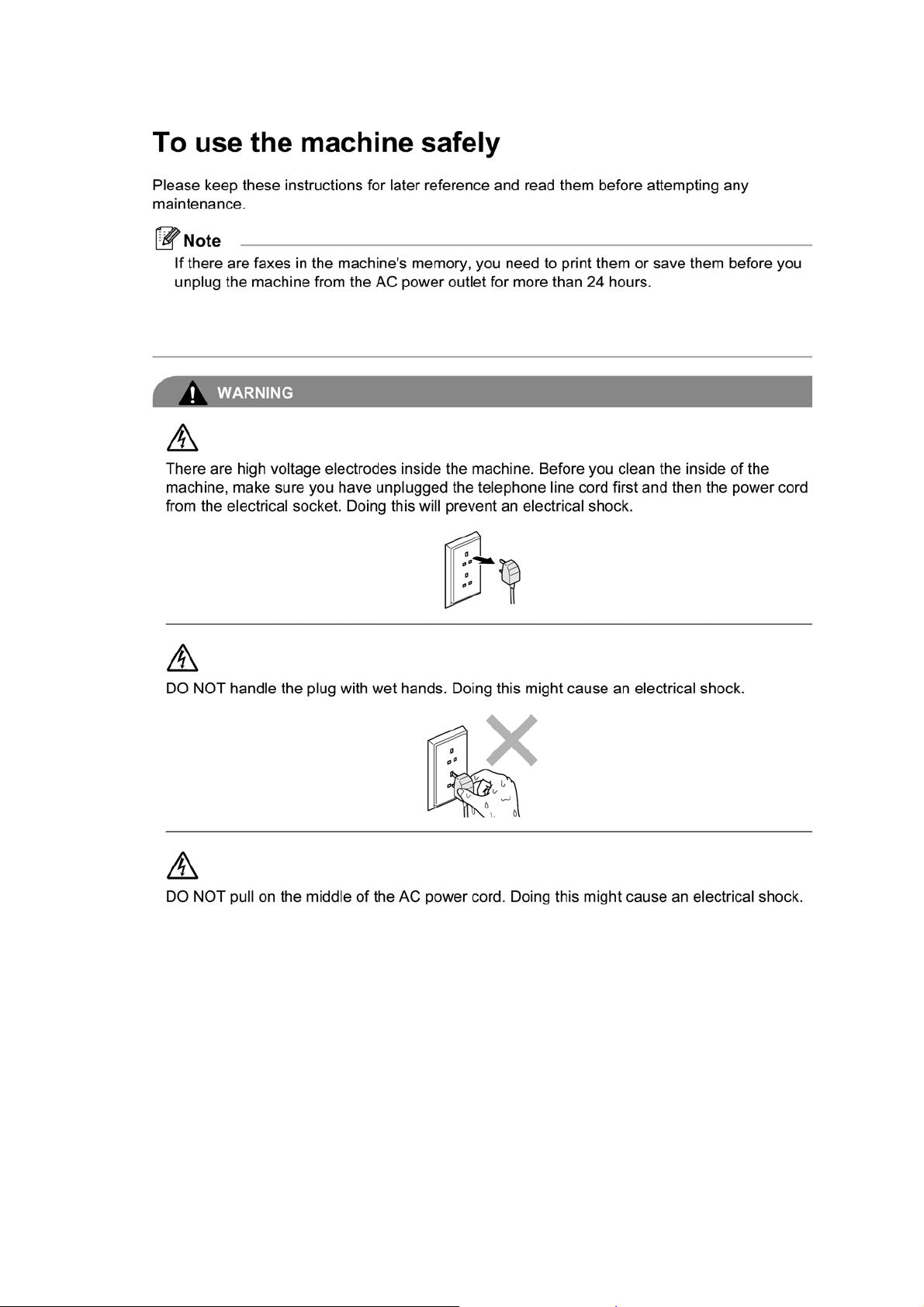
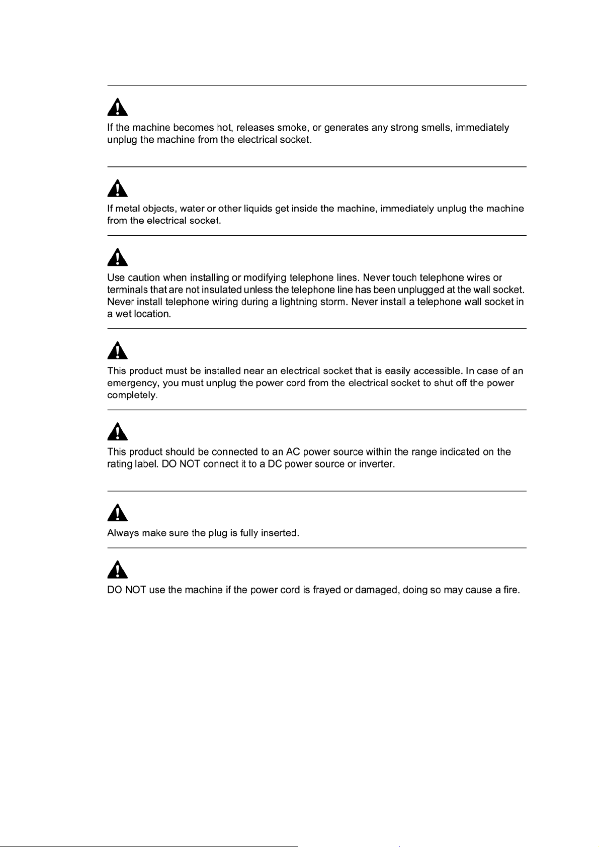
SAFETY INFORMATION
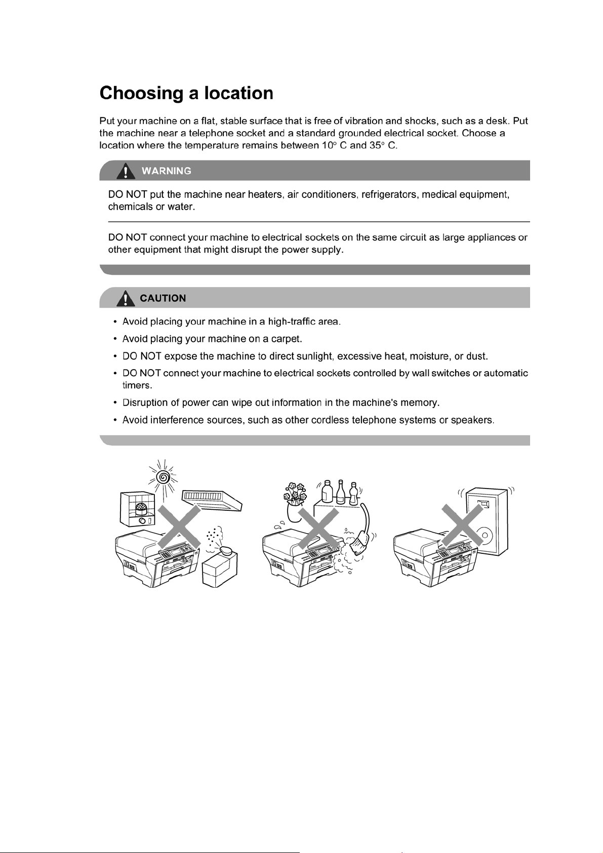
WARNING
WARNING indicates a potentially hazardous situation which, if not avoided, could result in
death or serious injuries.
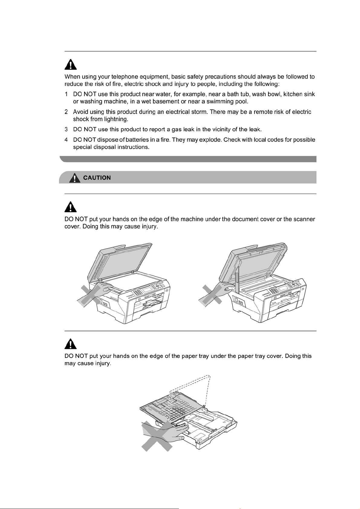
CAUTION
CAUTION
or moderate injuries.
indicates a potentially hazardous situation which, if not avoided, may result in minor
IMPORTANT
IMPORTANT
damage to property or loss of product functionality.
Follow all warnings and instructions marked on the machine.
indicate a potentially hazardous situation which, if not avoided, may result in
Notes tell you how you should respond to a situation that may arise or give tips about
how the operation works with other features.
Electrical Hazard icons alert you to possible electrical shock.
v
Confidential
vi
Confidential
vii
Confidential
viii
Confidential
ix
Confidential
x
Confidential

xi
Confidential

xii
Confidential
xiii
Confidential

CHAPTER 1
PARTS NAMES AND FUNCTIONS
Confidential

CHAPTER 1 PARTS NAMES AND FUNCTIONS
This chapter contains external views and names of components and describes their functions.
Information about the keys on the control panel is included to help you check operation or make
adjustments.
CONTENTS
1.1 OUTLINE................................................................................................................1-1
1.2 CONTROL PANEL ....... ...... ....... ...... ....... ...... ....... ...... ...... ....... ...... ....... ...................1-3
1.3 COMPONENTS......................................................................................................1-6
Confidential
1.1 OUTLINE
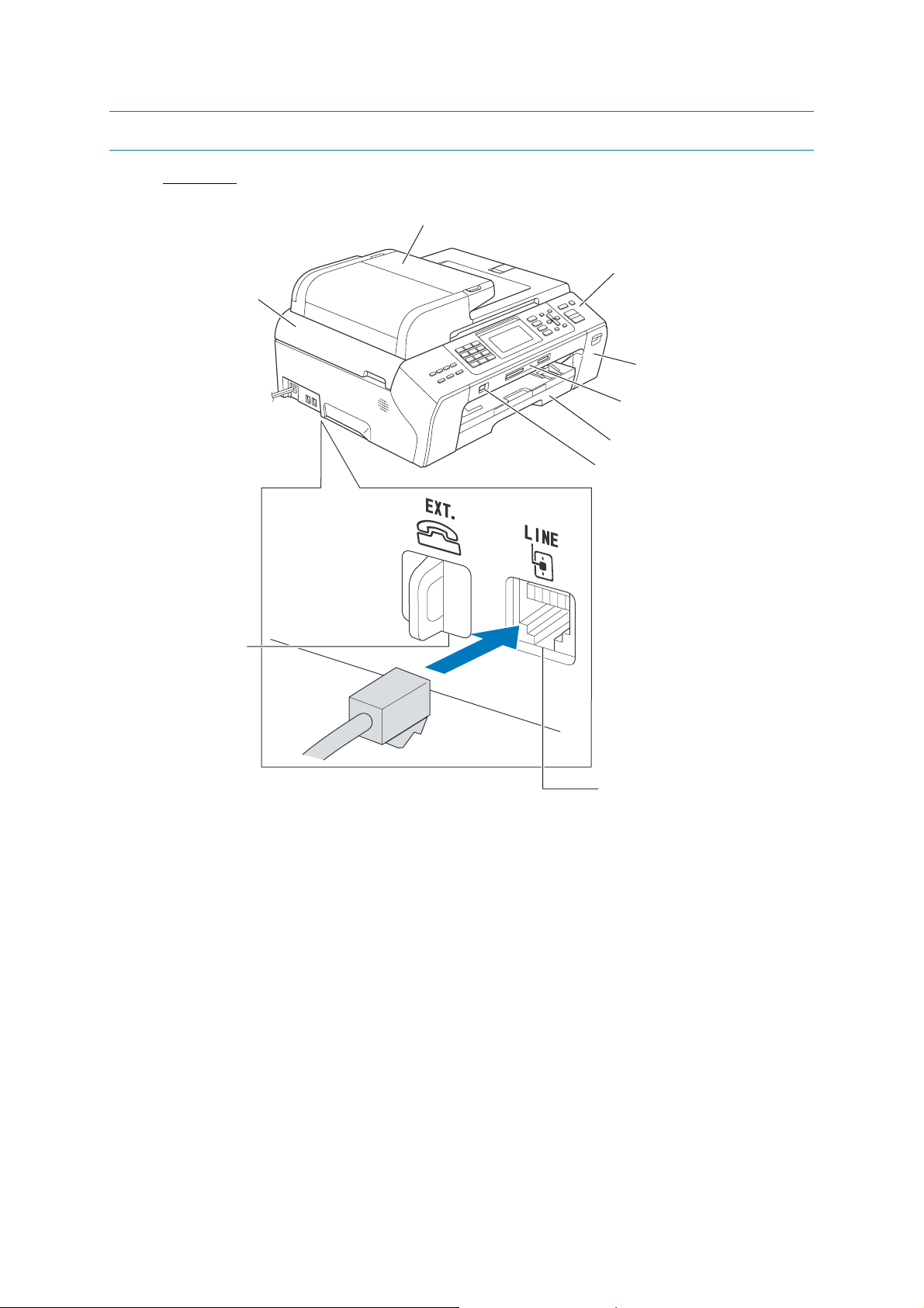
Front view
(1) ADF & document cover ASSY
(9) Scanner cover
(Scanner unit)
(8) External telephone
line jack
(2) Control panel
(3) Ink cartridge cover
(4) Media slots for
PhotoCapture Center
(5) Paper tray
(6) Port for PictBridge /
USB flash memory drive
1-1
(7) Telephone line jack
(frontview)
Confidential
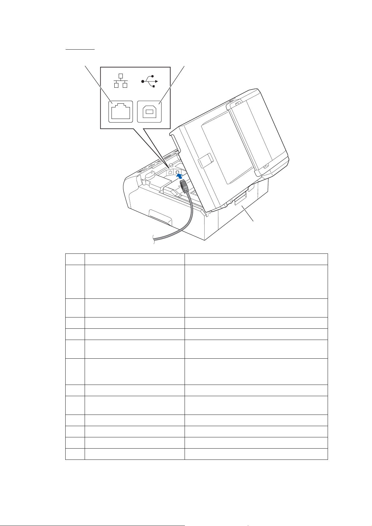
Back view
(12) LAN cable connector
LAN USB
(11) USB interface connector
(10) Jam clear cover
(backview)
No. Name Description
ADF: Load documents (originals) here. Documents
(1) ADF & document cover ASSY
will be fed into the machine, page by page.
Document cover: Open to place the document
(original) on the scanner glass.
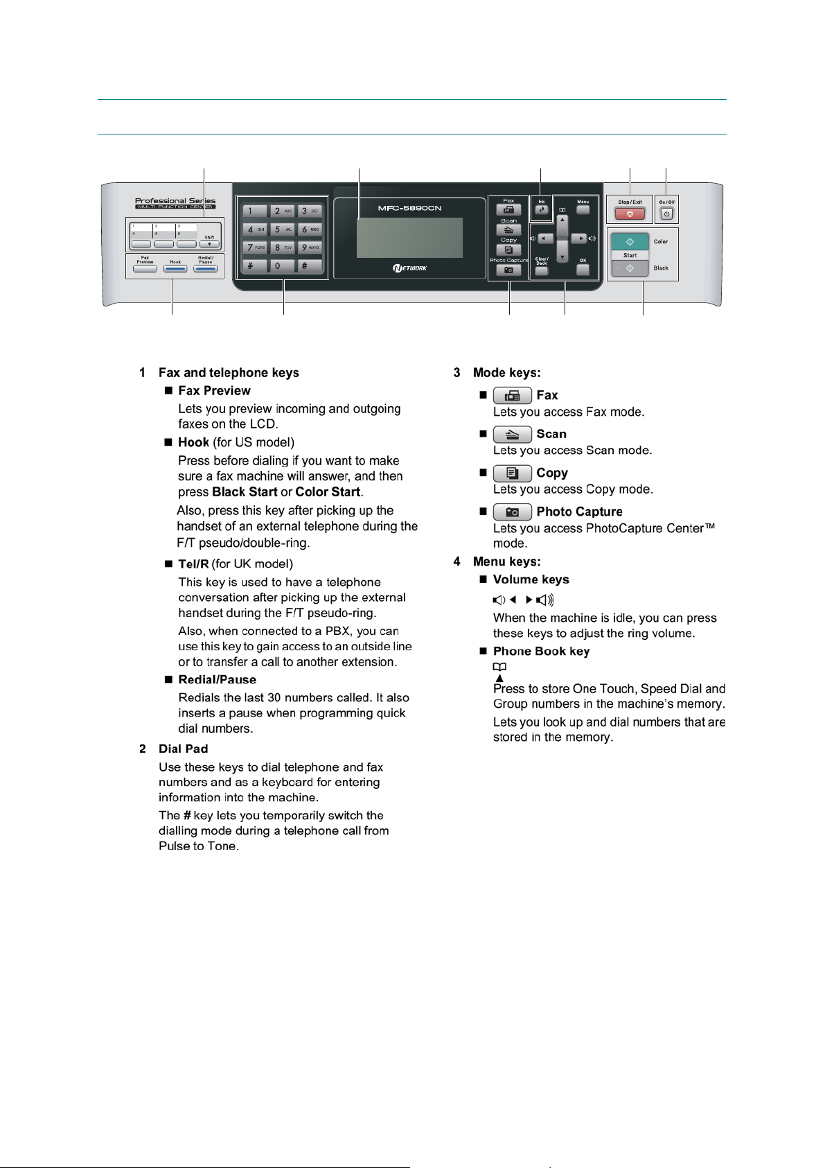
(2) Control panel
Use the keys to operate the machine. The liquid crystal
display (LCD) shows the machine operation status.
(3) Ink cartridge cover Open to replace ink cartridges.
(4) Media slots for PhotoCapture Center Insert a memory card here.
(5) Paper tray
Port for PictBridge / USB flash
(6)
memory drive
Telephone line jack
(7)
External telephone line jack
(8)
Load paper here. Paper will be fed into the machine,
sheet by sheet.
Connect a digital camera (with PictBridge) to this
connector using the USB cable.
Insert a USB flash memory drive her e.
Plug in the modular plug on the telephone line here.
Plug in the modular plug o n the external tel ephone line
here.
(9) Scanner cover (Scanner unit) Open to remove jammed paper.
(10) Jam clear cover Open to remove paper jammed inside the machine.
(11) USB interface connector Connect the USB cable here.
(12) LAN cable connector Connect the LAN cable here.
1-2
Confidential
1.2 CONTROL PANEL
10
12
9
786
3
4
5
1-3
Confidential
1-4
Confidential
1-5
Confidential
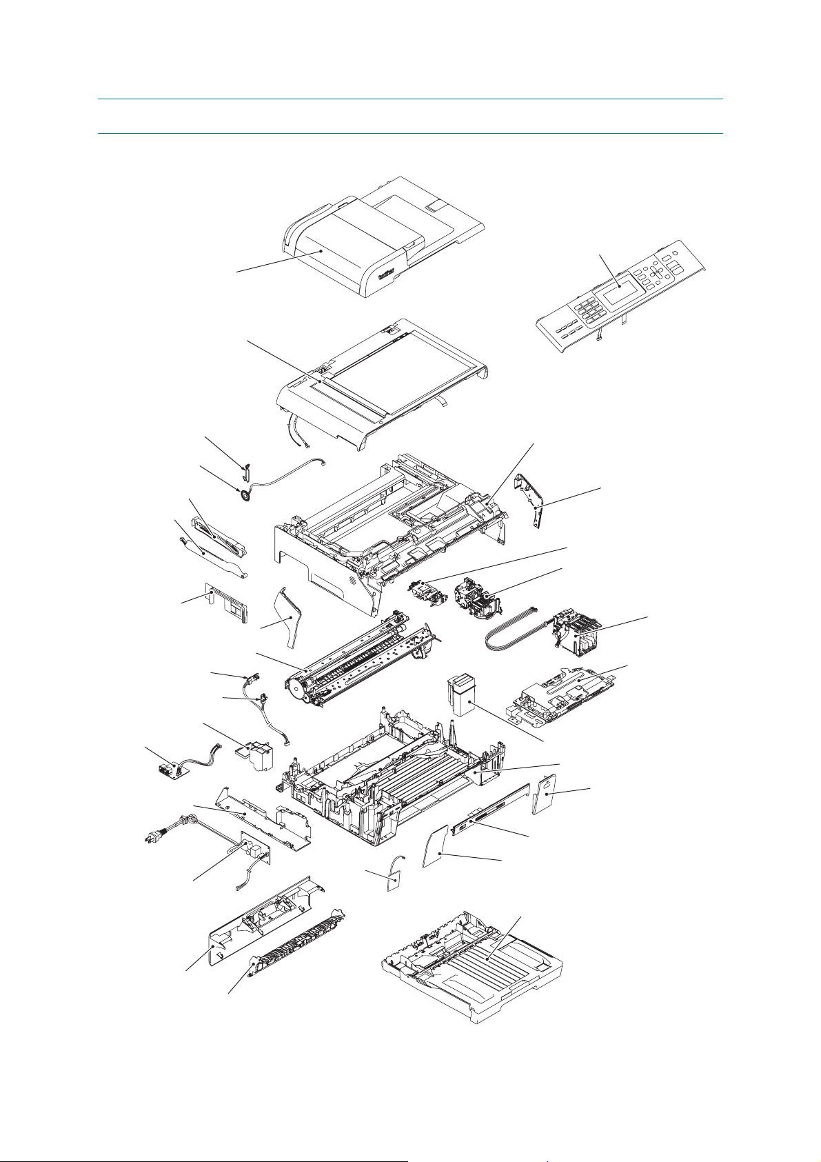
1.3 COMPONENTS
The machine consists of the following major components:
ADF & document cover
ASSY
Scanner cover
(Scanner unit)
Control panel ASSY
Wire spring
Speaker
Scanner cover damper
Scanner cover
support
MJ side cover
Registration sensor
PCB
PF encoder PCB
Flushing box
MJ PCB
MJ/PS shield unit
Upper cover
Side cover R
Head/carriage unit
Maintenance unit
Ink refill ASSY
Side cover L
Engine unit
Main PCB ASSY
Ink absorber box
Lower cover
Ink cartridge cover
Power supply PCB
Jam clear cover
Inner back cover
WLAN
PCB*
1-6
Media module cover
Front cover
Paper tray ASSY
(COMPONENTS_BHL9_MFC5890CN)
* For wireless LAN-enabled model.
Confidential

CHAPTER 2
SPECIFICATIONS
Confidential

CHAPTER 2 SPECIFICATIONS
This chapter lists the specifications of each model, which enables you to make a comparison of
different models.
CONTENTS
2.1 GENERAL ..............................................................................................................2-1
2.1.1 Media Specifications..................................................................................2-2
2.1.2 Paper Handling...... ....... ...... ....... ...... ....... ...... ...... ....... ...... ....... ...................2-2
2.1.3 LCD/LED/Panel.........................................................................................2-3
2.1.4 Memory .....................................................................................................2-3
2.1.5 Security .....................................................................................................2-3
2.1.6 Interface ....................................................................................................2-4
2.1.7 Others........................................................................................................2-4
2.2 TELEPHONE..........................................................................................................2-5
2.2.1 Volume ......................................................................................................2-5
2.2.2 Quick/Auto Dials........................................................................................2-5
2.2.3 Tel Service.................................................................................................2-6
2.2.4 Message Center........................................................................................2-6
2.2.5 List/Report.................................................................................................2-6
2.3 FAX.........................................................................................................................2-7
2.3.1 Sending .....................................................................................................2-8
2.3.2 Receiving...................................................................................................2-8
2.3.3 PC FAX......................................................................................................2-9
2.4 PRINTER................................................................................................................2-9
2.5 COPY .....................................................................................................................2-10
2.6 SCANNER..............................................................................................................2-11
2.7 PHOTO CAPTURE.................................................................................................2-12
2.7.1 PictBridge..................................................................................................2-13
2.8 SOFTWARE ...........................................................................................................2-13
2.9 NETWORK .............................................................................................................2-14
2.9.1 Wired.........................................................................................................2-14
2.9.2 Wireless.....................................................................................................2-15
2.10 SUPPLIES/OPTIONS.............................................................................................2-16
2.11 SERVICE INFORMATION......................................................................................2-16
Confidential

2.12 PAPER....................................................................................................................2-17
2.12.1 Paper Specifications ..... ...... ....... ...... ....... ...... ...... ....... ...... ....... ...... ....... ......2-17
2.12.2 Printable Area............................................................................................2-20
Language List ..................................................................................................................2-21
ITU-T Test Chart #1.........................................................................................................2-22
Brother Chart ...................................................................................................................2-23
Confidential

2.1 GENERAL
Model MFC5890CN MFC5895CW
Technology Inkjet
Print Head 94 nozzles/line, 5 lines
Variable Dot Print Yes (3 sizes)
Minimum Droplet Size
Scanning Method CIS
CPU Speed RISC 192 MHz
Backup Clock Yes
Simultaneous Operation Yes
U.S.A. Yes (Letter size)
Demo
Sheet
Panel Key
Demo
for Demo
LCD
Demo
Tes t Print Print Quality & Alignment Check Sheet (by pressing the Ink key . )
Europe
Asia/
Oceania
U.S.A.
Europe
Asia/
Oceania
U.S.A. Yes
Europe
Asia/
Oceania
FAX + COPY (Print + LCD demo)
BK: 4 pl
CMY: 1.5 pl
N/A
N/A
N/A
N/A
N/A
N/A
2-1
Confidential

2.1.1 Media Specifications
Model MFC5890CN MFC5895CW
A3, A4, LGR, LTR, LGL, EXE, B4 (JIS), B5 (JIS), A5, A6, Photo (102 x 152 mm/4 x 6 inches),
Indexcard (127 x 203 mm/5 x 8 inches), Photo-L (89 x 127 mm/3.5 x 5 inches),
Photo-2L (127 x 178 mm/5 x 7 inches), Post Card 1 (100 x 148 mm/3.9 x 5.8 inches),
Media
Sizes
Media
Weights
Media
Types
Standard Tray
Photo Tray
Lower Tray
Duplex Print
ADF
(width/length)
Scanner Glass
(width/length)
Standard Tray 64-220 g/m
Photo Tray
Lower Tray
Duplex Print
ADF 64-90 g/m
Standard Tray Plain, Inkjet, Glossy (cast/resin coated), Transparency
Photo Tray
Lower Tray
Duplex Print
ADF Plain
Post Card 2 (Double) (148 x 200 mm/5.8 x 7.9 inches), C5 Envelope, Com-10,
DL Envelope, Monarch, JE4 Envelope
N/A
N/A
N/A
148/148 mm to 215.9/355.6 mm (5.8/5.8 inches to 8.5/14.0 inches)
Up to 215.9/297 mm (up to 8.5/11.7 inches)
2
(17-58 lb.)
N/A
N/A
N/A
2
(17-24 lb.)
N/A
N/A
N/A
2.1.2 Paper Handling
Model MFC5890CN MFC5895CW
Standard Tray 150 (80 g/m
Paper Input
(sheets)
Output Paper Capacity
(sheets)
Photo Tray
Lower Tray
ADF 50 (90 g/m
N/A
N/A
50 (80 g/m
2
)
2
)
2
)
2-2
Confidential
2.1.3 LCD/LED/Panel
Model MFC5890CN MFC5895CW
Type & Size 3.3-inch Wide Color LCD
Touch Panel
Backlight & Color Yes
LCD
Language
Selectable Wallpaper Yes (4 patterns)
Illuminated Key/LED Fax/Scan/Copy/Photo Capture
Illuminated Key Color Blue
Status LED Color
U.S.A.
Europe See "Language List (page 2-21)."
Asia/
Oceania
U.S.A.: English/Spanish,
Canada: English/Canada-French
N/A
English/Spanish
N/A
2.1.4 Memory
Model MFC5890CN MFC5895CW
Memory Capacity
(physical: megabytes)
Memory Backup
(with battery, 24 hours)
Backup Print: ON/OFF
(in function menu)
64 MB
Yes
Yes
2.1.5 Security
Model MFC5890CN MFC5895CW
Memory Security
Transmission Lock
Secure Function Lock Yes
2-3
N/A
N/A
Confidential
2.1.6 Interface
Model MFC5890CN MFC5895CW
Host Interface USB 2.0 Hi-Speed
LAN Yes
Wireless LAN
Bluetooth
IrSimple
PictBridge Yes
USB Flash Memory Yes
Acceptable Media Cards
N/A Yes
N/A
N/A
"Compact Flash"
"Memory Stick"
"Memory Stick Pro"
"Secure Digital"
"Secure Digital High Capacity"
"xD Picture Card"
"xD Picture Card TypeM/TypeM+/TypeH"
2.1.7 Others
Model MFC5890CN MFC5895CW
On/Off Switch Yes
U.S.A. 100-120 VAC, 50/60 Hz
Power Source
Operating Environment
Tem perature (Best Print
Quality)
Humidity 20 - 80% (w/o condensation)
Power
Consumption
Average
(Operating/
Standby/Sleep/
OFF mode)
Machine Noise (Operating) 50 dBA (Maximum) (Belgium only)
Machine Dimensions 485 x 408 x 242 mm
Machine Weight
Energy Star Compliant Yes
Blue Angel
TCO99
Speaker Yes
Europe/
Asia/
Oceania
U.S.A. 28 / 6.5 / 4 / 0.9 W
Europe/
Asia/
Oceania
U.S.A.
Europe/
Asia/
Oceania
U.S.A.
Europe Yes
Asia/
Oceania
220-240 VAC, 50/60 Hz
5-40 (18-33) degrees centigrade
28 / 6.5 / 4 / 0.9 W
10.7 kg
(23.6 lb.)
10.9 kg
(24.0 lb.)
N/A
N/A
N/A
2-4
Confidential

2.2 TELEPHONE
Model MFC5890CN MFC5895CW
Handset
Digital Cordless Phone
(Cordless Handset)
SKYPE API support
Hook/ Tel R/
Recall/On Hook
Key
Duplex Speaker Phone Key
PBX Feature (Europe Only) Yes
Hold/Mute
Music on Hold
Monitoring the Line on Hold
with Music
U.S.A. H ook
Europe Tel R
Asia/
Oceania
N/A
N/A
N/A
Hook
N/A
N/A
N/A
N/A
2.2.1 Volume
Model MFC5890CN MFC5895CW
Handset Volume
Speaker V olume Yes (3 steps + OFF)
Ring Volume Yes (3 steps + OFF)
N/A
2.2.2 Quick/Auto Dials
Model MFC5890CN MFC5895CW
One Touch Dial
Speed Dial 80 x 2 numbers
Figures of One T ouch & S peed
Dial
Registerable Number Of
Characters
Group Dial (Up to X groups) Yes (6)
Telephone Index
(Search/Speed dial key)
Yes - 6 locations
(3 keys + Shift key)
20 digits
16 characters
Yes
2-5
Confidential

2.2.3 Tel Service
Model MFC5890CN MFC5895CW
Caller ID Yes
Call Waiting Caller ID
Call from Caller ID List Yes
Call from Call List Yes
Call waiting Ready
Backup Caller ID list Yes
Call List Indication Yes
External TAD Interface Yes
Distinctive Ringing Yes
N/A
N/A
2.2.4 Message Center
Model MFC5890CN MFC5895CW
TAD
ICM Recording Time
Toll Saver
Recording Conversation
OGM/User Recording Time
(MC/TAD, F/T)
N/A
N/A
N/A
N/A
N/A
2.2.5 List/Report
Model MFC5890CN MFC5895CW
Activity Report/Journal Report Yes (up to 200)
Transmission Verification
Report
Help List Yes
Caller ID List Yes
Quick Dial List Yes (Print/Display)
Tel Index List ABC
User Setting List Yes
Order Form
Network Configuration Yes
Yes
N/A
2-6
Confidential

2.3 FAX
Model MFC5890CN MFC5895CW
Modem Speed 33,600 bps
Transmission Speed Approx. 3 seconds (Brother #1, MMR)
ITU-T Group Super G3
Coding Method
Paper Handling Size LTR, A4, LGL (with ADF)
Document Scanning Width
Document
Color FAX
Display FAX
Super Fine Yes (TX & RX : B&W only)
Gray Scale
Contrast
(Auto/S.Light/S.Dark)
Dual Access Yes (B&W only)
Enhanced Remote Activate Yes
Station ID
Remote Maintenance Yes
Remote Access Ye s
Fax Retrieval Yes (B&W only)
Paging Yes (U.S.A. only)
(Send/Receive)
Memory (Send/
Receive)
Send Yes
Receive Yes
Mono: MH/MR/MMR
Color: JPEG
LTR (FB): 208 mm
A4 (FB): 204 mm
LTR/LGL (ADF): 208 mm
A4 (ADF): 208 mm
Yes/Yes (ITU-T color FAX)
No/Yes (ITU-T color FAX)
Mono: 64,
Color: 256
Yes
Yes
20 digits/20 characters
2-7
Confidential

2.3.1 Sending
Model MFC5890CN MFC5895CW
Delayed Timer Up to 50 / B&W only
Polled
Sending
(type)
*B&W only
Batch Transmission Yes (B&W only/not color)
Quick-Scan
(Memory transmission)
(ITU-T Test Chart #1 on page
2-22)
Memory
Transmission
Broadcasting (Speed/
One Touch + Manual)
Manual Broadcasting Yes (50 locations)
Fax Forwarding Yes (B&W only)
U.S.A. Yes (Standard)
Europe/Asia/
Oceania
ITU-T Test
Chart #1
(see page 2-
22) / MMR
Brother Chart
(see page 2-
23) / MMR
Yes (Standard/Secure)
Approx. 3.30 seconds/page @LTR
Approx. 3.50 seconds/page @A4
Up to 400 pages
Up to 480 pages
Yes (216 locations)
2.3.2 Receiving
Model MFC5890CN MFC5895CW
Easy Receive/Fax Detect Yes (Fax detect only)
Polling
Receiving
(type)
* B&W only
Auto Reduction Yes
Out-of-Paper
Reception
U.S.A. Yes (Standard/Sequential)
Europe/Asia/
Oceania
ITU-T Test
Chart #1
(see page 2-
22) / MMR
Brother Chart
(see page 2-
23) / MMR
(Standard/Sequential/Secure/Timer)
Yes
Up to 400 pages
Up to 480 pages
2-8
Confidential

2.3.3 PC FA X
Model MFC5890CN MFC5895CW
Color/Mono Mono (A4 only)
Sending Yes (Network/USB)
Receiving
PC-Fax Protocol
Broadcasting Up to 50
Yes (Network/USB),
N/A for MAC
RX: Class 2
TX: PC-FAX Driver
2.4 PRINTER
Model MFC5890CN MFC5895CW
Mono/Color
Print Speed (A4/LTR)
*Including paper feeding
Resolution
(horizontal x vertical)
Fonts (CD Based)
Auto Duplex Print
Manual Duplex Print Yes
(Mono: 450 x 300 dpi/Color: 600 x 15 0 dpi):
<Borderless printing>
On: 0, 0, 0, 0 mm/0, 0, 0, 0 inch (*)
Off: 3, 3, 3, 3 mm/0.12, 0.12, 0.12, 0.12 inches (**)
Color
Up to 35/28 ppm
Up to 1200 x 6000 dpi
N/A
N/A
Print Paper Margin
(upper, lower, left, right)
Easy Print Setting for Printer
Driver (Japan only)
Color Enhancement
(Color Printer)
(*) Borderless for A3, A4, B4, LGR, LTR, A6,
Photo (102 x 152 mm/4 x 6 inches),
Index card (127 x 203 mm/5 x 8 inches),
Photo-L (89 x 127 mm/3.5 x 5 inches),
Photo-2L (127 x 178 mm/5 x 7 inches),
Post Card 1 (100 x 148 mm/3.9 x 5.8 inches) only
(**) 12, 24, 3, 3 mm/0.47, 0.95, 0.12, 0.12 inches for Envelops
N/A
Yes
2-9
Confidential

2.5 COPY
Model MFC5890CN MFC5895CW
Mono/Color (Color Copy) Color
Copy Speed (A4/LTR)
*Including paper feeding
**Europe's default is calculated
by "normal mode" speed
Resolution
(horizontal x
vertical)
Multi Copy
Reduction/Enlargement (%) 25 - 400 in 1% increments
N in 1
Poster Yes (3 x 3, 2 x 2)
Auto Skew Adjustment
Fit to Page Yes
Copy
Enhancement
Duplex Copy
Print Paper Margin
(upper, lower, left, right)
Paper Sizes
(Color Copy)
Mono
Color
Stack Yes (99)
Sort Yes
Book Copy
(Shadow
Correction &
Skew
Adjustment for
book)
Watermark
Copy
Standard T ray LGR, LTR, LGL, A3, A4, A5, 10 x 15 cm (4 x 6 inches)
Photo Tray
Lower Tray
Print: Maximum 1200 x 1200 dpi
Scan: Maximum 1200 x 1200 dpi
Print: Maximum 1200 x 1200 dpi
Scan: Maximum 1200 x 1200 dpi
LGR/LTR/A3/A4 only (*Mono & Color)
3, 3, 3, 3 mm/0.12, 0.12, 0.12, 0.12 inches
23/20 cpm
8/8 cpm (Belgium only)
2 in 1 / 4 in 1
N/A
Yes
Yes
N/A
N/A
N/A
2-10
Confidential

2.6 SCANNER
Model MFC5890CN MFC5895CW
Mono/Color (Color Scanner) Color
Scan Speed (Mono/Color)
*@100 dpi
Resolution
(horizontal x
vertical)
Gray Scale 256
Scan to
Document Scanning Width 210 mm
Color Depth Input: 48 bits, Output: 24 bits
Optical 1200 x 2400 dpi
Interpolated
Image Yes (Scan Key)
OCR Yes (Scan Key)
E-mail Yes (Scan Key)
File Yes (Scan Key)
Media
(Media Card
or USB Flash
Memory)
FTP Yes (Scan Key)
E-mail Server Yes (Download/Scan Key)
(For Windows XP/Vista, up to 19200 x 19200 dpi with Scanner Utility)
Maximum 3.24/4.55 seconds (LTR)
Maximum 3.44/4.83 seconds (A4)
1200 x 1200 dpi
Yes (Scan Key)
2-11
Confidential

2.7 PHOTO CAPTURE
Model MFC5890CN MFC5895CW
Memory Stick: 16-128 MB (Duo with Adapter)
Memory Stick Pro: 256 MB - 8 GB
(MagicGate: YES if not use MG function)
Secure Digital: 16 MB - 2 GB (MiniSD with
Acceptable
Media
(Type & Size)
Paper Sizes
Paper Types
Print Paper Margin (upper,
lower, left, right) (PCC)
Available Paper Size for Full
(Maximum) Size Printing
Direct Print Size for A4/LTR
(N/A for A3, LGR, B4)
Borderless/Cropping
(Full Auto)
Media Format
Image Format Print by Media
Card/USB Flash Memory
Color Enhancement
(PCC)
Removable Disk (Media Card/
USB Flash Memory)
Scan to Media (Media = Media
Card or USB Flash Memory)
Network Media Card/USB
Flash Memory Access
Monochrome/Sepia Yes
Trimming Yes
Search from D a te Yes
Slide-show Yes
Photo Enhance
Media Cards
USB Flash
Memory
Standard T ray LGR, LTR, A3, A4, 10 x 15 cm (4 x 6 inches), 13 x 18 cm (5 x 7 inches)
Photo Tray
Lower Tray
Standard T ray Plain, Inkjet, Glossy
Photo Tray
Lower Tray
Adapter)
Secure Digital High Capacity (SDHC): 4-8 GB
xD Picture Card: 16-512 MB
xD Picture Card TypeM/Ty peM+/ TypeH:
256 MB - 2 GB
Compact Flash: 4 MB - 8 GB
(Type1 only, Type2 & Microdrive are not
compatible)
Up to 8 GB Up to 32 GB
N/A
N/A
N/A
N/A
<Borderless printing>
On: 0, 0, 0, 0 mm/0, 0, 0, 0 inch
Off: 3, 3, 3, 3 mm/0.12, 0.12, 0.12, 0.12 inches
All sizes
8 x 10 cm (3 x 4 inches), 9 x 13 cm (3.5 x 5 inches), 10 x 15 cm (4 x 6 inches),
13 x 18 cm (5 x 7 inches), 15 x 20 cm (6 x 8 inches), Maximum Size
Yes/Yes
DPOF (Ver. 1.0, Ver. 1.1)
Exif DCF (Up to Ver. 2.1)
Photo Print: JPEG/JPEG
Yes
Yes (read & write)
(both Card & USB flash memory)
Color: JPEG/PDF
B&W: TIFF/PDF
Yes (read & write)
(both Card & USB flash memory)
Yes
(Remove red-eye/Skin-Tone/Scenery/Auto correct)
Memory Stick: 16-128 MB (Duo, micro with
Adapter)
Memory Stick Pro: 256 MB - 32 GB
(MagicGate: YES if not use MG function)
(Duo, micro with Adapter)
Secure Digital: 16 MB - 2 GB (MiniSD,
microSD with Adapter)
Secure Digital High Capacity (SDHC): 4-32
GB
xD Picture Card: 16-512 MB
xD Picture Card TypeM/TypeM+/TypeH:
256 MB - 2 GB
Compact Flash: 4 MB - 32 GB
(Type1 only, Tpye2 & Microdrive are not
compatible)
2-12
Confidential

2.7.1 PictBridge
Model MFC5890CN MFC5895CW
Paper Size A3, A4, LGR, LTR, 4 x 6 inches, Printer Setting
Paper Type Plain Paper, Inkjet Paper, Glossy, Printer Setting
Direct Print Size for A4/LTR Maximum size only
Borderless / Cropping
(Full Auto)
Index Print
DPOF Yes
Color Enhancement Yes
Print Quality Normal, Fine, Printer Setting
Yes/No
N/A
2.8 SOFTWARE
Model MFC5890CN MFC5895CW
Support OS
Version
PC Application
Windows Windows 2K/XP/XP Professional x64/Vista
Mac Mac OS X 10.2.4 (greater) Mac OS X 10.4.11, 5.x, 6.x
Win 2K Professional
Win XP Home/XP Professional
Win XP Professional x64
Win Vista
Win Server 2003 (print only via network)
Win Server 2003 x64 (print only via network)
Win Server 2008 (print only via network)
Mac OS X 10.3.9 - 10.4.3
Mac OS X 10.4.4 or greater
Windows 2K/XP/XP Professional X64/
Vista/Win7
Windows® 2000 Professional
Windows® XP Home
Windows® XP Professional
Windows® XP Professional x64 Edition
Windows Vista®
Windows7
Windows Server® 2003 (print only via network)
Windows Server® 2003 x64 Edition
(print only via network)
Windows Server® 2003 R2
(print only via network)
Windows Server® 2003 R2 x64 Edition
(print only via network)
Windows Server® 2008 (print only via network)
Windows Server® 2008 R2
(print only via network)
Mac OS® X 10.4.11, 5.x
Mac OS® X 10.6.x
2-13
Confidential

2.9 NETWORK
Model MFC5890CN MFC5895CW
ITU SUB Addressing
Printer Yes
Scanner Yes
PC FAX Yes
Internet FAX (Firmware) Yes (Download)
Format (Scan to E-mail server)
ARP, RARP, BOOTP, DHCP, APIPA (Auto IP), NetBIOS/WINS, LPR/LPD,
Protocols (IPv4)
Protocols (IPv6)
LDAP
FAX to E-mail Y e s
Network Management
(BRAdmin Light)
Network Management (MIB-II
as well as Brother private MIB)
Network Reset Yes (for WLAN & WIRED LAN at once) (in LAN Menu)
Custom Raw Port/Port9100, DNS Resolver, mDNS, FTP Server, TELNET,
SNMPv1, TFTP, Scanner Port, LLTD Responder, Web Services, SMTP Client,
POP before SMTP, SMTP- AUTH, POP3, APOP, FTP Client
(Turned off by default) NDP, RA, LPR/LPD, Custom Raw Port/Port9100, mDNS,
FTP Server, TELNET, SNMPv1, TFTP, Scanner Port, LLTD Responder, Web Services,
SMTP Client, POP before SMTP, SMTP-AUTH, POP3, APOP, FTP Client
N/A
Color: PDF/JPEG
B/W: TIFF/PD F
N/A
Yes
Yes
2.9.1 Wired
Model MFC5890CN MFC5895CW
Model Name (Ethernet) Embedded (NC-170h)
Network Connection (Ethernet) Ethernet 10/100 BASE-TX Auto Negotiation
2-14
Confidential

2.9.2 Wireless
Model MFC5890CN MFC5895CW
Model Name (Wireless)
Network Connection
(Wireless)
Wireless Security
WiFi Certification
WCN
(Windows Connect Now)
Secure EZ
Setup
Setup Support
Utility
Auto Switch WLAN/WIRED
LAN
AOSS
(WLAN model
only)
WPS (WiFi
Protected
Setup)
N/A Embedded (NC-180w)
N/A IEEE 802.11b/g
N/A
N/A Wifi B and G
N/A
N/A
N/A Yes
N/A Yes
N/A
SSID (32 chr), WEP 64/128 bit,
WPA-PSK (TKIP/AES), WPA2-PSK (AES)
**NO LEAP**
2-15
Confidential

2.10 SUPPLIES/OPTIONS
Model MFC5890CN MFC5895CW
LC61BK/ LC65HY-BK
U.S.A.
Ink Cartridge Model
Name
Bundled Ink Cartridge Type High yield
Bundled Cartridges Approx. 770/540 pages
Ink
Cartridge
Yield
(@ISO
pattern/
normal)
Brother Paper (for
Plain, Glossy and
Inkjet)
Recommended Paper Only for
Transparency
Supply Standard
Cartridges
Supply Low Yield
Cartridges
Supply High Yield
Cartridges
Europe
Asia/
Oceania
U.S.A.
Europe/
Asia/
Oceania
Glossy (resin coated): LGR/LTR/4 x 6 inches
Glossy (resin coated): A3/A4/4 x 6 inches
LC61C/ LC65HY-C
LC61M/ LC65HY-M
LC61Y/ LC65HY-Y
LC1100BK/ LC1100HY-BK
LC1100C/ LC1100HY-C
LC1100M/ LC1100HY-M
LC1100Y/ LC1100HY-Y
LC67BK/ LC67HY-BK
LC67C/ LC67HY-C
LC67M/ LC67HY-M
LC67Y/ LC67HY-Y
Approx. 450/325 pages
N/A
Approx. 900/750 pages
Plain: LGR/LTR
Inkjet: LGR/LTR
Plain: A3/A4
Inkjet: A3/A4
3M 3410 Transparency Film
2.11 SERVICE INFORMATION
Model MFC5890CN MFC5895CW
Monthly Volume 4000 pages
Machine Life (year) 50000 pages or 5 years
MTBF (Mean Time Between
Failures)
MTTR (Mean Time To Be
Repaired)
2-16
4000 hours
30 minutes
Confidential

2.12 PAPER
2.12.1 Paper Specifications
Paper type and size for each operation
Paper Type Paper Size Usage
Fax Copy Photo
Capture
Cut Sheet Ledger 11 x 17 inches (279.4 x 431.8 mm) Yes Yes Yes Yes
A3 11.7 x 16.5 inches (297 x 420 mm) Yes Yes Yes Yes
Letter 8 1/2 x 11 inches (215.9 x 279.4 mm) Yes Yes Yes Yes
A4 8.3 x 1 1.7 inc he s (210 x 297 mm ) Yes Yes Yes Yes
Legal 8 1/2 x 14 inches (215.9 x 355.6 mm) Yes Yes -- Yes
Executive 7 1/4 x 10 1/2 inches (184 x 267 mm) -- -- -- Yes
B4 (JIS) 10.1 x 14.3 inches (257 x 364 mm) -- -- -- Yes
B5 (JIS) 7.2 x 10.1 inches (182 x 257 mm) -- -- -- Yes
A5 5.8 x 8.3 inches (148 x 210 mm) -- Yes -- Yes
A6 4.1 x 5.8 inches (105 x 148 mm) -- -- -- Yes
Cards Photo 4 x 6 inches (10 x 15 cm) -- Yes Yes Yes
Photo L 3 1/2 x 5 inches (89 x 127 mm) -- -- -- Yes
Photo 2L 5 x 7 inches (13 x 18 cm) -- -- Yes Yes
Index Card 5 x 8 inches (127 x 203 mm) -- -- -- Yes
Post Card 1 3.9 x 5.8 inches (100 x 148 mm) -- -- -- Yes
Post Card 2
(Double)
Envelopes C5 Envelope 6.4 x 9 inches (162 x 229 mm) -- -- -- Yes
DL Envelope 4.3 x 8. 7 inches (110 x 220 mm) -- -- -- Yes
COM-10 4 1/8 x 9 1/2 inches (105 x 241 mm) -- -- -- Yes
Monarch 3 7/8 x 7 1/2 inches (98 x 191 mm) -- -- -- Yes
JE4 Envelope 4.1 x 9.3 inches (105 x 235 mm) -- -- -- Yes
Transparencies Letter 8 1/2 x 11 inches (215.9 x 279.4 mm) -- Yes -- Yes
A4 8.3 x 1 1.7 inc he s (210 x 297 mm ) -- Yes -- Yes
5.8 x 7.9 inches (148 x 20 0 mm) -- -- -- Yes
Printer
Paper weight, thickness and capacity
Paper Type Weight Thickness No. of
2
Cut Sheet Plain Paper 17 to 32 lb. (64 to 120 g/m
) 3 to 6 mil (0.08 to 0.15 mm) 150
Inkjet Paper 17 to 53 lb. (64 to 200 g/m2) 3 to 10 mil (0.08 to 0.25 mm) 20
2
Glossy Paper Up to 58 lb. (Up to 220 g/m
Cards Photo 4 x 6 inches Up to 58 lb. (Up to 220 g/m
Index Card Up to 32 lb. (Up to 120 g/m
Post Card Up to 53 lb. (Up to 200 g/m
Envelopes 20 to 25 lb. (75 to 95 g/m
) Up to 10 mil (Up to 0.25 mm) 20
2
) Up to 10 mil (Up to 0.25 mm) 20
2
) Up to 6 mil (Up to 0.15 mm) 30
2
) Up to 10 mil (Up to 0.25 mm) 30
2
) Up to 20 mil (Up to 0.52 mm) 10
Transparencies -- -- 10
*
Up to 150 sheets of plain paper 20 lb. (80 g/m2).
2-17
sheets
Confidential
*

Recommended print media
Brother paper
Paper Type Item
Ledger Plain BP60PLGR (USA only)
Ledger Glossy Photo BP71GLGR
Letter Plain BP60PL (USA only)
Letter Glossy Photo BP71GP
Letter Inkjet (Matte) BP60ML (USA only)
4 x 6 in. Glossy Photo BP71GP
A3 Plain BP60PA3
A3 Glossy Photo BP71GA3
A3 Inkjet (Matte) BP60MA3
A4 Plain BP60PA
A4 Glossy Photo BP71GA4
A4 Inkjet (Matte) BP60MA
10 x 15 cm Glossy Photo BP71GP
2-18
Confidential

Handling and using print media
Store paper in its origin al pac kagi ng, an d keep i t sea led. K eep th e pape r flat a nd away fro m
moisture, direct sunlight and heat.
Avoid touching the shiny (coa ted) side o f ph oto pap er. Load p hoto pa per wi th the shiny s ide
facing down.
Avoid touching either side of transparencies because they absorb water and perspiration
easily, and this may cause decreased output quality. Transparencies designed for laser
printers/copiers ma y stain your next doc ument. Use only transpar encies recommended for
inkjet printing.
You can only print on both sides of the paper with PC printing using Windows.
1 0.08 inches (2 mm) or greater curve
may cause jams to occur
2-19
Confidential

2.12.2 Printable Area
Top (1) Bottom (2) Left (3) Right (4)
Cut Sheet 0.12 inches (3 mm) 0.12 inches (3 mm) 0.12 inches (3 mm) 0.12 inches (3 mm)
Envelopes 0.47 inches (12 mm) 0.95 inches (24 mm) 0.12 inches (3 mm) 0.12 inches (3 mm)
2-20
Confidential

Language List
Product
Category
MFC U.S.A. English English
Country Languages Default
Canada English/French English
Belgium Dutch/French/English Dutch
Switzerland German/French/English Germ an
Pan Nordic/Denmark English/Norwegian/Swedish/Finnish/
Danish
General English/Czech/Hungarian/Polish/
Bulgarian/Romanian/Slovak
Russia Russian/English Russian
Asia English English
Oceania English English
Hong Kong Traditional Chinese/English Traditional Chinese
Depends on first country
setting
English
2-21
Confidential

ITU-T Test Chart #1
2-22
Confidential

Brother Chart
2-23
Confidential

CHAPTER 3
THEORY OF OPERATION
Confidential

CHAPTER 3 THEORY OF OPERATION
This chapter gives an overview of the scanning and printing mechanisms as well as the sensors,
actuators, and control electronics. It aids in understanding the basic principles of operation as well as
locating defects for troubleshooting.
CONTENTS
3.1 OVERVIEW ............................................................................................................3-1
3.2 MECHANICAL COMPONENTS.............................................................................3-2
3.2.1 Scanner Mechanism..................................... ...... ....... ...... ....... ...................3-5
3.2.2 Printing Mechanism...................................................................................3-8
3.2.2.1 Ink supply and ink jet mechanism .........................................................3-10
[ 1 ] Overview ...........................................................................................3-10
[ 2 ] Features............................................................................................3-11
[ 3 ] Head/carriage unit.............................................................................3-12
[ 4 ] Ink cartridges........ ...... ....... ...... ....... ...... ...... ....... ...... ....... ...... ....... ......3-17
[ 5 ] Ink refill assembly. ...... ....... ...... ....... ...... .............................................3-19
[ 6 ] Ink supply tubes ................ ...... ....... ...... .............................................3-20
3.2.2.2 Head maintenance mechanism.............................................................3-21
[ 1 ] Overview ...........................................................................................3-21
[ 2 ] Maintenance unit components ..........................................................3-22
[ 3 ] Mechanisms constituting the head maintenance mechanism...........3-24
[ 4 ] Power transmission route to the head maintenance mechanism
and motor rotational direction............................................................3-29
[ 5 ] Purge types, ink usage, purge counts, and purge codes ..................3-32
[ 6 ] Ink cartridge capacities ........................................... ....... ...... ....... ......3-32
3.2.2.3 Carriage drive mechanism ....................................................................3-33
3.2.2.4 Paper pulling-in, registration, feeding and ejecting mechanisms..........3-37
3.2.3 Sensors and Actuators..............................................................................3-41
3.3 CONTROL ELECTRONICS ......................... ....... ...... ...... .......................................3-44
3.3.1 Components..............................................................................................3-44
Confidential

3.1 OVERVIEW
Line
Color
LCD
Fax Control Section
SDAA
MJ PCB
Control
panel
Speaker
ADF unit
- ADF motor
Backup
battery
Scanner unit
- CIS unit
- CIS motor
Host
USB
interface
WLAN*
WLAN
PCB
Ink jet printer unit
- Head/carriage unit
- Carriage PCB with
head flat cables
- Carriage motor
- Ink refill ASSY
- Maintenance unit
LAN
*
LAN
interface
Printer Control Section
Print data
- Compact Flash
- Memory Stick
- SD Memory Card
- xD-Picture Card
PhotoCapture
Center
Paper feeding
mechanism
- Paper feed
motor
- ASF motor
- Digital camera
(with PictBridge)
- USB flash
memory drive
USB
interface
Power
supply
AC
(Overview_BHL9_A3)
* For wireless LAN-enabled model.
3-1
Confidential

3.2 MECHANICAL COMPONENTS
This machine consists of the scanner mechanism and printing mechanism. It uses five motors
(CIS motor, ADF motor, paper feed motor, ASF motor, and carriage motor), three encoders (PF
encoder, ASF encoder, and CR encoder), various sensors, and two thermistors.
Scanner Mechanism
Document path for ADF scanning
(Left)
Document for flat-bed scanning
Printing Mechanism
Ink supply and ink jet mechanism, head maintenance mechanism, and carriage drive
mechanism.
(Right)
(BHL9A3_ADF_1)
(Front)
- Carriage drive mechanism
3-2
(Rear)
- Ink supply and ink jet mechanism
- Head maintenance mechanism
(3_01_BHL9_A3)
Confidential

Paper pulling-in, registration, feeding and ejecting mechanisms
Recording paper path
(Front)
(Rear)
(3_02_BHL9_A3)
3-3
Confidential

Scanner Mechanism
(See Section 3.2.1.)
- Document scanning mechanism CIS motor
(stepping motor)
Printing Mechanism
(See Section 3.2.2.)
Encoders
(See Section 3.2.3.)
- Automatic document feeder (ADF)
mechanism
- Ink supply and ink jet mechanism
(See Section 3.2.2.1.)
- Head maintenance mechanism
(See Section 3.2.2.2.)
(Head capping and carriage lock)
+
(Purge, air removing, and head wiper)
-Carriage drive mechanism
(See Section 3.2.2.3.)
- Paper pulling-in, registration, feeding
and ejecting mechanisms
(See Section 3.2.2.4.)
- Paper feed motor encoder (PF encoder)
- ASF motor encoder (ASF e ncoder)
- Carriage motor encoder (CR encoder)
ADF motor
(stepping motor)
ASF motor*
(DC motor)
+
Paper feed motor
(DC motor)
Carriage motor
(DC motor)
ASF motor*
(DC motor)
+
Paper feed motor
(DC motor)
Sensors
(See Section 3.2.3.)
Thermistors
(See Section 3.2.3.)
- Document front sensor
- Document rear sensor
- Scanner cover sensor
- Ink cartridge cover sensor
- Registration sensor
- Paper width (media) sensor
- Purge cam switch
- Cap lift cam switch
- Ink empty sensors (black, yellow, cyan and magenta)
- Ink cartridge detection sensors (black, yellow, cyan and magenta)
- Head thermistor
- Casing internal temperature thermistor
* ASF motor: Auto Sheet Feeder motor
3-4
Confidential

3.2.1 Scanner Mechanism
This mechanism consists of the automatic document feeder (ADF), document cover, and
scanner unit (scanner cover).
The scanner unit consists of a scanner top cover, CIS unit, CIS drive assembly, and scanner
base.
The detailed illustration on the nex t page s hows the components making up the ADF: document
pull-in roller, document separation roller, document feed rollers, document ejection rollers,
ADF motor, and document front and rear sensors.
For further details on the sensors, see Section 3.2.3.
ADF unit
ADF & document
cover ASSY
Document cover
White reference film
CIS drive assembly
(CIS motor)
CIS unit
Scanner top cover
CIS drive belt
CIS flat cable
Scanner unit
(Scanner cover)
Scanner base
CIS idle pulley
CIS rail
(3_03_BHL9)
3-5
Confidential

Document feed rollers
Document pressure rollers 1
Document separation roller
Document pull-in roller
Document support
Document ejection rollers
Document path for ADF scanning
(Left)
CIS unit
Document rear sensor actuator
Document pressure rollers 2
Pinch rollers
ADF motor
Document front sensor actuator
ADF parts
Document pressure bar
Document for flat-bed scanning
(BHL9A3_ADF_2)
(Right)
The scanner mechanism offers two types of scanning: ADF scanning and flat-bed scanning. It
automatically swi tches to the for mer a t t he start of a scan operation if the document front sensor
inside the ADF detects a document.
3-6
Confidential

(1) ADF scanning: Document moves acros s stationary CIS unit
Placing a doc um ent face up in the ADF activates the document front sensor, switching to ADF
scanning.
The CIS drive mechanism (details below) operates for each scanning command executed. First,
the CIS mot or moves the CIS unit to the white reference film for white level compensation.
Secondly, the ADF motor rotates the docu me nt pul l-in roller to pul l the document int o t he ADF.
Thirdly, the CIS motor again moves the CIS unit to the ADF scanning position.
The document separation roller feeds the pages one at a time, starting from the top, to the
document feed roller, which rotates to move the page in a curve left, down, and right. The page
is scanned as it passes over the CIS unit. It then leaves the machine face down onto the
document cover. The machine ejects subsequent pages above this one to preserve the document
page order.
(2) Flat-bed scanning: CIS unit moves under stationary document
The user lifts the document cover, places a page (or open book) face down with the left and top
edges fitting on the left and top guidelines on the glass plate, and closes the document cover.
The CIS drive mechanism (details below) operates for each scanning command executed. The
CIS unit first moves to the white reference film for white level compensation. It then moves
right, scanning as it goes. It returns to its home position after the scan.
CIS drive mechanism
The contact image sensor (CIS) unit rides along the CIS rail, driven by the CIS drive belt.
Clockwise motion of the CIS motor moves the unit to the left; counterclockwise motion, to the
right.
This unit consists of the document illumination LED array, the lens array gathering the light
reflected from the scanned image, the CIS PCB converting the light input to pixel data output,
and the CIS glass.
The CIS unit used in the machine supports color scanning. In scanning color documents, the
CIS unit illuminates them by turning on the red (R), green (G), and blue (B) LEDs alternately.
In scanning monochrome documents, it turns on the green LEDs only.
3-7
Confidential

3.2.2 Printing Mechanism
The printing mechanism co nsists of the following.
Ink supply and ink jet mechanism (Section 3.2.2.1)
Head maintenance mechanism (Section 3.2.2.2)
Carriage drive mechanism (Section 3.2.2.3)
Paper pulling-in, registration, feeding and ejecting mechanisms (Section 3.2.2.4)
The ink supply mechanism
supplies ink to the head/carriage unit, in which the ink jet
mechanism sprays ink droplets from the head nozzles onto paper.
The major components of the ink supply mechanism (shown on page 3-10) are:
- Ink refill assembly: This secures the ink cartridges and connects them to the corresponding
ink supply tubes.
- Ink supply tubes: These supply the head/carriage unit with ink fed from the ink cartridges via
the ink refill assembly.
The major components of the ink jet mechanism (head/carriage unit shown on page 3-12) are:
- Front end: This is an ink-jet head consisting of piezoelectric plate (PZT), metal plates, nozzle
plate, and head driver.It jets out ink to produce images on paper.
- Back end: This consists of damper assemblies and air vent unit. Each damper assembly
dampens the ink pressure fluctuations in the corresponding ink supply tube and collects air
bubbles that result from pressure changes on the ink.
To keep the optimum head performance, the head maintena nce mechanism
(shown on page 3-
31) uses the rotational torque of the ASF motor* to cap the head nozzles in order to prevent
them from drying up. It also uses the rotational torque of the paper feed motor to purge for
removing air bubbles from the head/carriage unit and wipe off any ink remaining on the head
nozzle surface.
The carriage drive mechanism
(shown on page 3-33) moves the head/carriage unit with a
carriage motor (DC motor) along the recording paper. The CR encoder sensor mounted on the
head/carriage unit scans the CR encoder strip and monitors the current head position relative to
the home position and the current travel speed.
The paper pulling-in, registration, feeding and ejecting mechanisms
motor* and paper feed motor (both are DC motors).
The major components are:
- Paper tray: Recording paper is stored in this tray.
- Paper pull-in rollers (shown on page 3-38):
These rollers pull in paper into the machine.
- Bank ASSY (shown on page 6-73):
This separates paper, sheet by sheet to feed it into the
printing section.
- Jam clear cover (shown on page 3-37):
Opening this cover allows the user to access paper jammed.
It also guides paper pulled in from the paper tray into the
printing section.
*ASF motor: Auto Sheet Feeder motor
3-8
are driven by th e ASF
Confidential

- Paper feed roller (shown on page 3-38):
This roller performs paper registration and feeds paper to
the printing section precisely.
- Paper ejection roller (shown on page 3-37):
This roller ejects paper and keeps paper tension tight.
- ASF motor* (shown on page 3-38):
This motor pulls in paper, switches the paper feed operation
modes, and drives the head capping mechanism and
carriage lock mechanism of the maintenance unit.
- Paper feed motor (shown on page 3-38):
This motor feeds recording paper and drives the purge
mechanism, air removing mechanism and head wiper
mechanism of the maintenance unit.
- Clutch gears L and R (shown on page 3-38):
Clutch ge ar L switches the transm ission route of the AS F
motor rotation between the paper pulling-in mechanism and
the head capping & carriage lock mechanisms.
Clutch gear R transmits the rotational torque of the paper
feed motor to the purge gear (for purge, air removing and
head wiper mechanisms).
- ASF rotary encoder: This generates a signal indicating the rotation speed of the
ASF motor shaft. The signal is sent to the controller and
used for controlling the paper pull-in position and speed.
- PF rotary encoder: This generates a signal indicating the rotation speed of the
PF roller gear. The signal is sent to the controller and used
for controlling the paper feed position and speed.
*ASF motor: Auto Sheet Feeder motor
3-9
Confidential

3.2.2.1 Ink supply and ink jet mec hanism [ 1 ] Overview
The ink supply and ink-jet mec hanism con sist s of the he ad/car riag e unit, four ink cart ridge s, ink
refill assembly, and four ink supply tubes.
The head/carriage unit scans the surface of the recording paper, jetting out ink supplied through
the ink supply tubes onto the paper to produce images. For further details, see "[ 3 ] Head/
carriage unit" below.
The four ink cartridges (black, yellow, cyan, and magenta) are mounted on the ink refill
assembly. For further details, see "[ 4 ] Ink cartridges" below.
The ink refill assembly secures the ink cartridges and connects them to the corresponding ink
supply tubes. For further details, see "[ 5 ] Ink refill assembly" below.
The ink supply tubes supply the head/carriage unit with ink fed from the ink cartridges via the
ink refill assembly. For further details, see "[ 6 ] Ink supply tubes" below.
(Maintenance unit)
Head/carriage unit
(Flushing box)
Engine unit
(Ink absorber box)
Ink refill assembly
Ink supply tubes
(3_04_BHL9)
3-10
Confidential

[ 2 ] Features
A distinct feature of this machine is the use of ink supply tubes between the ink cartridges and
the head/carriage unit. Relieving the head/carriage unit of the task of carrying heavy ink
cartridges back and forth across the page, the approach generally adopted by other ink-jet
printers, offers the following advantages.
- Lower po wer consumption
- Lower noise levels
- Lower vibration
During print operation, the ink-jet mechanism inside the head/carriage unit sprays ink droplets
from the head nozzles. The loss of this ink from the head produces a negative pressure that
replenishes the head with ink from the ink tank through the supply tubes.
Note, however, that the above ink flow is only possible when the ink supply tubes are full of
ink. The factory therefore primes the ink supply path by applying strong suction to the head
nozzles with the maintenance unit to suck both air and ink through the ink supply tubes.
Leaving too long interval between this priming and actual use, however, risks air bubbles,
increased viscosity, and other quality issues with the ink in the supply tubes. Before using this
machine for the first time, therefore, this machine automatically replaces the ink supply path
contents with fresh ink using an initial purge, a repeat of this priming operation.
When the machine is on standby, a constant negative pressure (which is produced according to
the difference in height between the head/carriage unit and ink cartridges) is applied to the rear
of the print head, thus preventing ink from leading out of those nozzles.
Note: The above applies only as long as this machine rests on a horizontal surface. Standing
this machine on end or even just tilting it backwards with the print head uncapped risks
overcoming this slight negative pressure preventing ink leakage from the head nozzles.
Piezoelectric ceramic actuators inside the print head convert this ink to droplets sprayed onto
the paper. For further details, see "[ 3 ] Head/carriage unit" below.
3-11
Confidential

[ 3 ] Head/carriage unit
)
(
)
The head/carriage unit con sist s of a fr ont end ( ink-j et hea d) a nd a back e nd (damper and air vent
unit) as shown below.
The front end consists of metal plates laminated together and etched to form ink flow channels.
Piezoelectric ceramic actuators generate the spray pressure. The response of individual front
ends to applied voltages and waveforms varies, however, because of the nature of piezoelectric
materials, fluctuation in manufacturing accuracy, and other factors. The front end therefore
leaves the production line with head property labels giving property data. The manufacturer
writes this prope rty data to the EEPROM on the main PCB incorporating this unit. Based on the
property data of the front end, the processor drives piezoelectric ceramic actuators to insure
consistent performance without fluctuations.
Back end
(Buffer and air vent unit
(Front)
Head driver
Filter
Piezo plate
Metal plates
Front end
(Ink-jet head)
Nozzle plate
3-12
Head
Confidential

Front end
Front end components and their main roles
- Piezoelectric pla te
Applying a voltage stretches the plate, serving as the actuator for spraying ink. Consisting of
thin piezoelectric plates laminated together, this plate can be driven even by a low voltage.
- Filter
This removes foreign materials from the ink.
- Metal plates
These form the head nozzle pressure chambers, ink flow paths, and manifolds.
- Nozzle plate
This plate has a total of 470 nozzles--47 nozzles x 2 lines staggered x 5 rows (black x 2,
yellow, cyan, and magenta).
- Head driver
This flexible circuit board holds the piezoelectric driver chip.
Nozzle array (head bottom plate viewed from the bottom)
Yellow
Black
Black
Paper feed direction
Print head travel direction
Cyan
Magenta
Black
Black
Nozzles
Yellow
Channels
Cyan
Magenta
3-13
(Nozzle)
Confidential

Ink spray function
The head employs drop-on-demand ink-jet printing.
Print commands to the drive circuit apply a bias voltage to the layer electrodes on the
piezoelectric ceramic surface stretching the elements perpendicular to that surface. Drive
signals removing t hi s voltage for specif ic channel electrode s allow the piezoelect ri c elements to
return to their or iginal shape , suc king i nk into the co rresp ondi ng chann els*. Re applyi ng the b ias
voltage stretches the elements once again, applying pressure to the ink, spraying it from the
head nozzle. The ink drop hits the paper on the platen, forming a dot.
* Pressure chambers for individual nozzles
3-14
Confidential

Back end
Damper ASSY (Magenta)
Air bubbles
Left chamber
Damper ASSY (Cyan)
Air bubbles
Right
chamber
Left chamber
Damper ASSY (Y ellow)
Air bubbles
Left chamber
Damper ASSY (Black)
Air bubbles
Left chamber
Back end components and their main roles
Right chamber
Right
chamber
Right
chamber
Shut-off valves
Air vent unit
(Air vent rods)
(A part of maintenance unit)
(Air vent cap)
(BackEnd_E)
- Damper assemblies
Each assembly has two roles: dampening the ink pressure fluctuations* in the ink supply tube
as the carriage moves and collecting air bubbles that grow in the ink flow path.
* Ink pressure fluctuations: As the head/carriage unit travels, inertia means that the ink remains in the
same place, temporarily raising or lowering the pressure in the right chamber.
- Air vent unit
At regular scheduled in terva ls, thi s vents any air bubbl es that have accumul ate d in the damper
assemblies. The air ven t ro ds in the mai nt enance unit push up the shut-off valves, opening th e
air vent flow paths.
3-15
Confidential

Damping
Without damping, ink pressure fluctuations directly affect the size of ink-jet head droplets,
risking lower print quality.
Each damper assembly has two chambers. The one on the right in the illustration below has a
loose film across its top and serves as a damper. The film immediately flexes in and out in
response to falls and rises in pressure, adjusting the chamber volume to counteract pressure
fluctuations in the ink supply tubes.
Film
Left chamber
This loose film flexes in and out in
response to changes in ink pressure.
(DamperFunc)
Air buffering
Liquid ink contains trace amounts of air. These molecules coalesce into air bubbles as the
piezoelectric ceramic actuators vary t he pressure on the ink in the ink-jet head channel. (See the
illustration on page 3-13.) Removing as many of these bubbles as possible before the ink
reaches the in k-jet head is ess ential to main taining prop er print qualit y. The above ill ustration
shows how the damper assemblies provide air buffers, the chambers on the left, for
consolidating th ese ai r bu bbles a way fro m the ink-j et head and vent fl ow path s for pu r gi ng them
at regular scheduled intervals.
3-16
Confidential

[ 4 ] Ink cartridges
Filled with ink
Disc valve S
Sensor actuator
Air
Ink empty sensor
Ink
Disc valve D
Ink near-empty/Ink empty
Ink cartridge features
This machine uses four ink cartridges: a black one and three color ones with a slightly lower
capacity. It features horizontal insertion in the ink refill base over plastic needles.
Each cartridge has two ports: one supplying the ink for printing and another intaking air to
replace that ink. Both ports have a disc valve preventing ink leakage. When a cartridge is
mounted over the plastic needles in the ink refill base, these valves are opened to secure flow
paths for both the ink and the air.
(3_06)
These ink cartridges are single-use affairs. There is no provision for refilling them. The design
reduces environment load by using only burnable materials yielding no toxic substances.
Inks
This machine uses dye-based inks for colors and pigment-based ink for black. Using the
pigment-based black ink reduces fuzziness from print character outlines, boosts resolution for
black dots, and produces clearer images on plain paper.
3-17
Confidential

Ink near-empty/ink empty detection
The ink refill assembly has four ink empty sensors (photosensors of transparent type) that
monitor the ink levels with sensor actuators inside the ink cartridges.
Disc valve S
Air intake port
Air
Ink empty
sensor
Ink
Ink supply port
Ink empty sensor
Sensor actuator
Disc valve D
Sensor actuator
Float
(InkBackflowPrevention)
(InkEmptySensor_2)
Attached to one end of the sensor actuator is a float. When there is ink in the cartridge,
buoyancy lifts the float, rotating the sensor actuator about a pivot near the center of the actuator
to block the light beam to the ink empty sensor, indicating that there is ink.
As the ink level in t he ink cart ridge drops, howev er, th e fl oat f alls, event ually moving t he se nsor
actuator out of the beam.
Light hitting the s ensor outputs the "i nk ne ar -empt y" si gnal to the controll er t h at sho w s t he " I nk
low" message and activates a firmware counter tracking ink usage during ink-jet printing,
purges, and other operations. When this counter reaches a predetermined limit, the firmware
regards it as "ink empty" and shows the "Cannot Print" message to prompts the user to replace
it.
3-18
Confidential

[ 5 ] Ink refill assembly
Ink empty sensor PCB
Ink empty sensors
Cartridge release levers
Ink refill case
(3_07)
Ink cartridge detection sensors
Ink cartridge detection
sensor PCB
Ink foam case
Ink refill base
3-19
Ink foam
Ink refill base foam
(3_08)
Confidential

Ink refill as sembly components and thei r main roles
- Ink refill case
- Cartridge release levers
- Ink refill base and its foam
- Ink cartridge detection sensors (on the ink cartridge detection sensor PCB)
- Ink empty sensors (on the ink empty sensor PCB)
- Ink foam and its case
Pushing each ink cartridge into the ink refill case
until it clicks secures it and forces the
cartridges' ink supply port into close contact with the ink refill base to prevent ink leakage.
Pressing down the cartridge release lever
pops the ink cartridge out of the ink refill case.
The ink from the ink cartridges flows through the ink flow channels provided in the ink refill
base into the ink supply tubes. As the ink level in an ink cartridge drops, the pressure inside
falls, drawing air in the ink cartridge.
The ink cartridge detection sensors
detect ink car tridges inserted wh en the machine powe r is
ON.
The ink empty sensors
detect ink remaining in the ink cartridges loaded. An ink empty sensor
actuator blocking the light beam to an ink empty sensor indicates that there is ink in the ink
cartridge. When ink runs low, the actuator moves out of the beam, activating the sensor ("Ink
near-empty") and showing the "Ink low" message.
If any of the ink cartridges is replaced with the one having different ink volume when the
machine power is OFF, the corresponding ink cartridge detection sensor and ink empty sensor
issue different sig nal s when the power is turned ON next time so that the control ler prompt s th e
user to reload the ink cartridge.
At the back of the ink refill case is an ink foam
that absorbs any ink that leaks from the air
intake ports of the ink cartridges loaded when the machine is tilted during transportation or in
storage, preventing ink spread in the machine.
[ 6 ] Ink supply tubes
These are made of low-density polyethylene (LDPE) providing a highly impermeable barrier
against air ingress and drying out of the ink during extended periods of nonuse. This material is
also soft and highly flexible to better withstand the sharp and frequent bending associated with
high-speed head operation repeatedly over extended periods.
3-20
Confidential

3.2.2.2 Head maintenance mechanism [ 1 ] Overview
The head maintenance mechanism, which keeps the optimum head performance, consists of the
maintenance unit and the ink absorber box. (See the illustration below.)
The maintenance unit has the following mechanisms.
- Head capping mechanism (See page 3-24.)
- Carriage lock mechanism (See page 3-24.)
- Purge mechanism (See p age 3-2 5.)
- Air removing mechanism (See page 3-27.)
- Head wiper mechanism (See page 3-28.)
The ink absorber box absorbs the ink sucked out by purge operations.
(ASF motor)
Maintenance unit
(Head/carriage unit)
(Paper feed
motor)
(Flushing box)
(Engine unit)
Ink absorber box
(Ink refill assembly)
(Ink supply tubes)
(3_09_BHL9)
3-21
Confidential

[ 2 ] Maintenance unit components
k
(3_10)
Pump switching unit
Purge gear
Cap lift cam
Cap lift
cam gear
(ASF changeover
gear)
Head wiper
Maintenance unit
- Cap lift cam and its gear
These parts transmit the rotational torque of the ASF motor transmitted via the clutch gear L
to the head cap holder. (See [ 4 ] "Power transmission route to the head maintenance
mechanism and motor rota tional direction.")
- Head cap unit
When the power is off or the machine is not printing, the head cap unit fits tightly over the
print head to prevent the head nozzles from drying up and to seal the head nozzles for purge
operations to suck up old ink.
Air vent cap
Air vent rods
Carriage loc
(Part of head
cap holder)
Head cap holder
Head cap unit
Viewed from the top Viewed from the b ot t om
Purge cam
Purge bevel gear
(ASF changeover gear)
Cap lift cam gear
Purge gear
Planetary arm
Tube pump
(3_11)
- Head cap holder
This lifts up the head cap unit to fit it tightly over the print head to seal the head nozzles. (The
had cap holder is driven by the ASF motor.)
- Carriage lock
This is a part of the head cap hol der. It locks the head/carriage uni t in it s home posit ion so that
the head cap unit protects the head nozzles.
- Purge gear and purge bevel gear
These gears transmit the rotational torque of the paper feed motor via the clutch gear R to the
planetary arm. (See [ 4 ] "Power transmission route to the head maintenance mechanism and
motor rotational direction.")
-Planetary arm
This switches the rotational t orque of the paper feed motor ( t ran smitted via the purge gear a nd
purge bevel gear) to the pump switching unit or tube pump depending on the direction of
paper feed motor rotation .
-Purge cam
This rotating cam drives the pump switching unit, the air vent rods, and the head wiper. Each
drive position of the purge cam is detected by the purge cam switch. (See Section 3.2.3.)
3-22
Confidential

- Pump switching unit
This switches the application target of the negative pressure generated by the tube pump
between the head cap for black ink, the one for color ink, and the air vent cap. Usually the
pump switching un it is switc hed to the openin g tube to the at mospheri c air so that the pr es sure
in the head caps and air vent cap is equal to the normal atmospheric pressure.
- Air vent cap and rods
The air vent cap and rods remove air bubbles trapped in the damper assemblies in the back
end of the head/carriage unit.
During air venting with the tube pump, the air vent cap fits tightly over the ai r vent uni t in the
head/carriage unit so that the negative pressure applies to the air vent unit. Pushing up the air
vent rods opens the shut-off valves inside the air vent unit, removing air bubbles trapped in
the damper assemblies. (For the air vent unit, see Section 3.2.2.1, [ 3 ].)
- Head wiper
As the head/carriage unit moves, this wipes off any ink remaining on the head nozzle surface.
- Tube pump
A roller squeezes the main drain tube looped inside, forcing their contents toward the ink
absorber box and creating negative pressure.
3-23
Confidential

[ 3 ] Mechanisms constituting the head maintenance mechanism
p
(1) Head capping mechanism
The ASF motor drives the head capping mechanism. When the power is off or the machine is
not printing, this mechanism fits the head cap unit (which contains two head caps) tightly over
the print head to prevent the head nozzles from drying up and to keep dust off the head nozzle
surface.
The head cap unit is mounted on the head cap holder and supported by the spring.
When the head/carriage unit returns to its home position, it presses the mode switching lever
(shown on pages 3-30 and 3-31) to the ri ght s o that the cl utch gear L enga ges wi th the cap l ift
cam gear (p urge mod e). D rivi ng the A SF m oto r ro tates the cap lift cam so th at the c ap l ift ar m
raises the head cap holder, fitting it tightly over the head nozzle surface.
Purge gear
Cap lift cam
Cap lift cam gear
ASF changeover gear
Cap lift arm
Head cap unit
Head ca
Carriage lock
(Part of head cap holder)
holder
(3_12)
(2) Carriage lock mechanism
This mechanism locks the head/carriage unit to prevent the head nozzles fro m gett ing out of the
head cap unit accidentally due to external vibration or impact when the machine is not printing,
when the power is off, or during transport.
A part of the head cap holder acts as a carriage lock. When the head cap holder rises in head
capping operation, the carriage lock also comes up to lock the head/carriage unit.
3-24
Confidential

(3) Purge mechanism
The paper feed motor drives the purge mechanism.
The counterclockwise rotation of the paper feed motor drives the purge cam that aligns the
pump switching unit with either the black or color ink drain position.
Next, the paper feed motor reverses to activate the tube pump, producing negative pressure to
drain the air and old ink from the head nozzles and channels into the ink absorber box.
Purge cam
Pump switching unit
Main drain tube
Purge bevel gear
ASF changeover gear
Cap lift cam gear
Main drain tube
Planetary arm
Tube pump
Color drain tube
Black drain tube
Main drain tube
Air vent tube
(3_14)
3-25
Confidential

(3.1) Switching pump
)
The pump switching unit switches the application target of the negative pressure generated by
the pump between the head cap for black ink, the one for color ink, and the air vent cap.
When the purge cam is in a head capping position and the head cap unit fits tightly over the
print head, the pump switching unit is switched to the opening tube to the atmospheric air so
that the pressure in the head caps and air vent cap returns to the normal atmospheric pressure.
Print head
Head cap for black ink
Head cap for color ink
Black drain tube
To air vent cap
Main drain tube
Color drain tube
Pump switching unit
(Purge_3_2_E)
To opening to
atmospheric air
(3.2) Drainin g ink
The tube pump consist s of a pump gear and tube roll er. As the pump gear rotates, the tube roller
on its circumference squeezes the main drain tube looped around the pump gear, forcing its
content toward the ink absorber box and creating negative pressure.
Main drain tube
Pump gear
Tube pump
Tube roller
(TubePump
For details about the power transmission route to the head maintenance mechanism, see [ 4 ]
below.
3-26
Confidential

(4) Air removing mechanism
k
g
Other two positions of th e pur ge cam shift two slide cams--one for bl ack i nk, t he o the r f or color
inks, producing vertical motion of a single air vent rod for black ink and three air vent rods for
color ink, respectively.
Pushing up the air vent rods opens the shut-off valves inside the air vent unit of the head/
carriage unit. Simu lt ane ousl y adding negative pressu re fr om the tube pump removes air trapped
in the damper assemblies.
Maintenance unit
Purge gear
Air vent rod for black ink
(Cap lift cam gear)
(ASF changeover gear)
Air vent rods for color in
Air vent cap
Slide cam for black ink
Slide cam for color ink
Damper ASSY (Magenta)
Air bubbles
Left chamber
Damper ASSY (Cyan)
Air bubbles
Left chamber
Damper ASSY (Y ellow)
Air bubbles
Left chamber
Pur
e cam
(3_16)
Right
chamber
Right chamber
Right
chamber
Shut-off valves
Air vent unit
Damper ASSY (Black)
Air bubbles
Left chamber
Right
chamber
3-27
(Air vent rods)
(A part of maintenance unit)
(Air vent cap)
(BackEnd_E)
Confidential

(5) Head wiper mechanism
(3_15)
After the purge operation, the purge cam pushes up the head wiper, wiping off any ink
remaining on the head nozzle surface as the head/carriage unit moves from right to left.
Purge gear
(Cap lift cam gear)
(ASF changeover gear)
Head wiper
Purge cam
3-28
Confidential

[ 4 ] Power transmission route to the head maintenance mechanism and motor rotational
direction
This mecha nism draws it s power from two motors-- the ASF motor (DC motor) in the right rear
corner of the engine chassis and the paper feed motor (DC motor) on the left side. The ASF
motor is mounted in the ASF motor holder combined with the maintenance unit.
ASF motor
→ Maintenance unit (head capping and carriage lock mechanisms)
As shown on the next page, th e ro tational torque of the ASF motor is a lwa ys t ran smitted via the
ASF/maintenance drive gear and idle gear 16 to the clutch gear L.
When the mode switching lever is in the left position (ASF mode), the clutch gear L also
meshes with the ASF changeover gear.
When the head/carriage unit moves to the right end of its travel, a tab on the carriage rear panel
pushes the mode switching lever to the right (purge mode). The clutch gear spring pushes the
clutch gear L to the right, away from the ASF changeover gear, to mesh with the cap lift cam
gear. This way, the ASF motor drives the head capping and carriage lock mechanisms. (See
page 3-31 for the related components.)
Paper feed motor
→ Maintenance unit (purge, air removing and head wiper mechani sms)
As shown on the next page, the paper feed motor drives the PF roller gear L that rotates the
paper feed ro ller. At the right end o f the roller is the PF ro ller gear R that alwa ys meshes w ith
the clutch gear R.
When the mode switching lever is in the left position (ASF mode), the clutch gear R does not
mesh with the purge gear but it is just idling.
When the head/carriage unit moves to the right end of its travel, a tab on the carriage rear panel
pushes the mode switching lever to the right (purge mode). The clutch gear spring pushes the
clutch gear R to the right to mesh with the purge gear.
As the paper feed motor ro tates coun tercl ockwis e, the pl anetar y arm meshes wit h the pur ge cam
(as shown below), driving the purge mechanism (pump switching unit), air removing
mechanism and head wiper mechanism. On the contrary, the clockwise motor rotation causes
the planetary arm to mesh with the tube pump gear, driving the purge mechanism (tube pump).
(See page 3-31 for the related components.)
Cap lift cam switch
Tube pump
ASF changeover gear
Cap lift cam gear
Planetary arm
3-29
Purge cam
Black drain tube
Main drain tube
Air vent tube
Pump switching unit
Color drain tube
Purge cam switch
(3_20)
Confidential

R
Clutch gear R
(Always engaged with
PF roller gear R)
Clutch gear L
ASF/maintenance drive gear
Idle gear 16
ASF motor
Mode switching lever
PF roller gear R
(ASF changeover gear)
Paper feed roller
Purge gear
Purge bevel gear
Planet gear
ASF motor holder ASSY
PF roller gear
Cap lift cam gear
Paper feed roller
Maintenance unit
(Front)
PF roller
gear L
Paper feed motor
3-30
(3_17_BHL9)
Confidential

ASF motor holder
ASSY
Clutch gear spring
Clutch gear L
Clutch gear R
ASF changeover gear
Cap lift cam gear
Cap lift cam
Purge gear
Head wiper
Mode switching lever
Purge cam
Head cap holder
Switching lever spring
Air vent cap
Air vent rods
Maintenance unit
Carriage lock
(part of head cap holder)
Head cap unit
(3_19)
ASF/maintenance drive gear
ASF motor holder
ASSY
Cap lift cam
Purge gear
Purge bevel gear
Tube pump
Planet gear
ASF motor gear
Planetary arm
Idle gear 16
Clutch gears (L & R)
ASF changeover gear
Pump switching unit
Cap lift cam gear
Maintenance unit
Purge cam
(3_18)
3-31
Confidential

[ 5 ] Purge types, ink usage, purge counts, and purge codes
Refer to the table given on page 9-48.
[ 6 ] Ink cartridge capacities
Ink Cartridge Type Contents Usable Portion*
Starter and bund led
cartridges
Black ink cartridge
High-yield type
Color ink cartridges 10.1 0 ml Approx. 8.59 ml
23.05 ml Approx. 21.11 ml
High-yield type 23.05 ml Approx. 21.11 ml
Black ink cartridge
Standard type 12.40 ml Approx. 10.59 ml
Spare ink cartridges
High-yield type 10.10 ml Approx. 8.59 ml
Color ink cartridges
Standard type 8.25 ml Approx. 6.55 ml
1
*
These are the values measured with an actual machine, not the guaranteed ones.
Note: The contents and usable portion of ink cartridges are subject to change without notice.
Note: Values given in the above tables are as of August 2008.
1
3-32
Confidential

3.2.2.3 Carriage drive mechanism
r
The head/carriage unit, which integrates the print head unit and carriage, is supported and
guided by the CR guide rail and CR support chassis. The CR timing belt transmits the carriage
motor rotation to the head/carriage unit. Clockwise motor rotations move the head/carriage unit
to the right; counterclockwise ones to the left.
The CR encoder sensor on the top of the head/carriage unit scans the CR encoder strip above
the CR support chassis to monitor the current head position relative to the home position. The
controller uses this signal for robust control ensuring uniform speed.
The CR encoder strip is a clear film striped in a 1/150 inch cycle. It offers a choice of three
travel speeds of the head/carriage unit, 57.7, 43.3 and 21.7 ips, to match the print resolution.
(Paper feed roller)
CR encoder strip
Head/carriage unit
CR guide rail
CR encoder sensor
Idle pulley
Carriage moto
pulley
Carriage motor
CR timing belt
CR support chassis
(3_21_BHL9)
3-33
Confidential

Adjusting the print head angle relative to carriage
For optimal image printing, the print head nozzle array must be perpendicular to the head/
carriage unit's line of travel. Manufacturing limitations, however, make perfect alignment
impossible during mas s pr oduc ti on. The angle must be adjus te d at the ind ivi dual machine level.
The following describes this adjustment mechanism's components and their roles.
Slider L, the slider, and the rib attach the head/carriage unit to the CR support chassis. The rib
acts as a pivot for the slider's damping springs pressing the head/carriage unit to the rear. Slider
L has a head skew adjuster knob that shifts the slider back and forth, adjusting the angle of this
backward pressure . Rot at ing th e head skew adjuster kn ob t ilts the entire head/carriage unit, thu s
adjusting the head nozzle vertical angle relative to the carriage unit's line of travel.
This knob offers 11 settings, from -5 to +5.
For the adjustment procedure, refer to Chapter 7, Section 7.2, [ 4 ].
Viewed from the bottom
Damping springs
CR encoder strip
CR timing belt
Rib
(Front)
Head skew adjuster knob
Slider L
Slider
(3_22)
3-34
Confidential

Height adjustment of the head/carriage unit
m
For optimal image pri nt ing, a pa ir of s lider ca ms mount ed on the head/c arri age unit s witches the
height of the head/carriage unit against the CR guide rail and support chassis between two
levels--2.3 mm (for thick paper and envelops) and 1.6 mm (for other types of paper) in order to
bring the optimum distance between the head nozzle surface and paper.
The slider cams can be switched by hitting against the stoppers at the right and left ends of the
CR guide rail and CR support chassis.
Head/carriage unit
Slider cam
CR guide rail
Slider ca
CR support chassis
(3_23_BHL9)
For "thick paper and envelopes" and "other types of paper":
The machine adjusts the distance from the platen to the head/carriage unit to 2.3 mm for "thick
paper and envelopes" and 1.6 mm for "other types of paper" in order to keep the distance ("a")
constant.
For "thick paper and envelopes"
Head nozzle surface
"a"
Paper
Platen
(3_23_1b)
(Paper other than thick paper and envelopes)
For "other types of paper"
Head nozzle surface
"a"
Paper
Platen
(3_23_1a)
(3_24_2)
3-35
(3_24_1)
Confidential

As listed below, the printer driver on the connected PC or the paper type setting on the machine
controls the slider cams to determine the height of the head/carriage unit.
Controlled by:
Adjustment for:
Thick paper and envelopes Other types of paper
Printer driver (in printing from the PC) Yes Yes
Paper type setting (in copying and
printing via PhotoCapture Center)
No Yes
3-36
Confidential

3.2.2.4 Paper pull ing-in, registration, feeding and ejecting mechanisms
r
These mechanisms are driven via a gear train by two motors--paper feed motor located on the
left side of the engine chass is and AS F motor in the r ight rea r corne r. (See the illust rati on on the
next page.)
The following illustration is a cross-sectional view of the machine viewed from the right. Place
the recording paper face down in the paper tray. This paper first proceeds to the rear, bends
upward, heads back toward the front, passes under the head/carriage unit for printing, and
finally comes out onto the top of the paper tray cover.
The machine supports two paper feed modes--"normal SF mode" and "high-speed feed mode."
Depending upon the selected print quality, either of these two modes applies as listed below.
Print Quality Fast, Normal Other quality
Paper Feed Mode High-speed feed mode Normal SF mode
Recording paper path
Paper ejection roller
(Front) (Rear)
Paper tray
Recording paper path
Paper pull-in gear shaft
Platen
Head/carriage unit
ASF idle gears 17
PF roller gear R
Clutch gears (R and L)
ASF/maintenance
drive gear
ASF changeove
gear
Jam clear cover
Paper pull-in rollers
Paper pull-in roller holder
(3_02_1_BHL9_A3)
3-37
Confidential

Power transmission routes of the ASF motor and paper feed motor
t
The rotational torque of the ASF mo tor is transmitted to the ASF/maintenance drive gear which
always meshes with the clutch gear L, as described in Section 3.2.2.2, [ 4 ].
When the mode switching lever is in the left position (normal SF or high-speed feed mode), the
clutch gear L also meshes with the ASF changeover gear which transmits the ASF motor
rotation via a gear train to the paper pull-in rollers.
The rotational torqu e of th e paper feed motor
is transmitted via the PF roller gear L to the paper
feed roller that advances paper to the printing start position.
Mode switching lever
Left position (ASF mode)
ASF motor
Clutch gear R
ASF/maintenance
drive gear
Idle gear 16
Clutch gear L
ASF changeover
gear
ASF idle gears 17
Right position (Purge mode)
Purge gear
Mode switching lever
Head/carriage uni
Paper pull-in gear shaft
Paper feed motor
PF roller gear L
PF motor gear
Ejection idle gear
PF timing belt
Paper feed roller
Paper pull-in
rollers
Paper ejection roller
Paper pull-in
gear shaft
ASF idle
gears 17
(Front)
(3_25_BHL9_A3)
3-38
Confidential

Normal SF and high-speed feed mode
Normal SF mode
1st stage
2nd stage
3rd stage
The ASF moto r rotates clockwise (when viewed from the output gear side) and its
rotational torque is transmitted to the ASF/maintenance drive gear that is always
connected v ia th e idle gea r 16 to the clut ch ge ar L . When the mode swit chi ng lev er
is placed in the left po sition, t he clut ch gear L also meshe s with t he ASF change over
gear.
The rotational torque is further transmitted from the ASF changeover gear via the
two ASF idle gears 17, p aper pul l-in gear sha ft and the gear tr ain in the pape r pull -in
roller holder. Consequently, the paper pull-in rollers turn in the forward direction to
pull in a sheet of paper loaded in the paper tray.
After the pulled-in paper pushes the registration sensor actuator to turn the sensor
on, the ASF moto r further rotates clockwise for the predetermined period to align
(register) the leading edge of the paper with the paper feed roller. (Registration)
The ASF motor stops and the paper feed motor s ta rt s r ot at ing clockwise to r otate the
PF roller gear L that ro ta tes the paper feed roller in the forward direction to advance
the paper to the printing start position.
The rotational torque of the PF roller gear L is also transmitted via the ejection idle
gear and PF timing belt to the paper ejection roller that rotates in the forward
direction to eject the paper printed.
High-speed feed mode
1st stage
Just as in the normal SF mode, the clockwise rotation of the ASF m otor pulls i n a
sheet of paper loaded in the paper tray.
The difference from the normal SF mode is that the paper feed motor also rotates
clockwise at the same time as th e ASF motor. The paper feed roller rotates in t he
forward direction.
2nd stage
When the paper fed by the paper pull-in rollers reaches the paper feed roller, the
roller is already rotating in the forward direction; therefore, the paper continues to
advance to the printing start position.
Registration sensor activation has no effect on the paper feeding operation in the
high-speed feed mode.
Even during printing of the first sheet of paper, the ASF motor keeps rotating
clockwise to rotate the paper pull-in rollers in the forward direction. Immediately
after the first sheet leaves the paper tray, the paper pull-in rollers continuously pull
in paper sheet by sheet. After the last sheet of paper advances to the printing start
position, the ASF motor stops.
The paper feed roller always rotates faster than the paper pull-in rollers; therefore,
the trailing edge of the preceding sheet will not overlap with the leading edge of the
subsequent one
Just as in the normal SF mode, the ro tational to rque of the P F roller ge ar L is also
transmitted via the ejection idle gear and PF timing belt to the paper ejection roller
that rotates in the forward direction to eject the paper printed.
3-39
Confidential

Other controls
Paper feed position and speed control
A PF encoder disk with the resolution of 300 dpi (0.084 mm pitch) is mounted on the PF roller
gear L. The PF encoder sensor uses it to generate a signal indicating the gear rotation speed--in
other words, the paper feed roller speed--to the controller for use in controlling paper feed
position and speed.
Paper stop position control
The controller uses the PF encoder signal for proportional, integration, differential (PID)
control of the paper feed motor to produce high-resolution precision paper positioning during
printing. This signal also determines the motor parameters for rapidly and precisely positioning
the paper.
Fixed-speed paper feed
This operation rotates the paper feed roller to feed the paper at a constant speed regardless of
load fluctuations. The primary application is ejecting paper when printing is complete--in other
words, in situations where precision stop position control is not needed.
Paper feeding amount control
There is variation in the head nozzle pitch of individual head/carriage units, as well as in the
shape of the paper feed and ejection rollers. To make those parts match each other, therefore,
updating the paper feeding correction value (Function code 58) is necessary (see Chapter 9,
Section 9.4.16).
3-40
Confidential

3.2.3 Sensors and Actuators
This machine uses the following sensors and thermistors.
Sensor Name
Document front sensor Photosensor
Document rear sensor Photosensor
Scanner cover sensor Carbon switch
Ink cartridge cover sensor Carbon switch
Registration sensor Photosensor On th e registration sensor PCB
Paper width sensor (media sensor) Photosensor
CR encoder sensor Photosensor
PF encoder sensor Photosensor On the PF encoder PCB
ASF encoder sensor Photosensor In the ASF motor unit
Purge cam switch Mechanical switch
Cap lift cam switch Mechanical switch
Casing internal temperature thermistor Thermistor
Ink empty sensors (four) Photosensor
Ink cartridge detection sensors (four) Photosensor
Sensor Type
On the document sensor PCB in the
ADF unit
On the control panel PCB
On the carriage PCBHead thermistor Thermistor
On the maintenance unit
On the ink emp ty sensor PCB inside
the ink refill assembly
On the ink cartridge detection sensor
PCB on the ink refill assembly
Location
• The document front sensor detects whether there is a document in the ADF.
• The document r ear sens or detect s the leadi ng and trai ling e dges of documen t pages , i ndicati ng
to the control circuitry the point at which to start reading and when page scanning is complete.
• The scanner cover sensor detects whether the scanner cover (scanner unit) is properly closed.
• The ink cartridge cover sensor detects whether the ink cartridge cover is properly closed.
• The registration sensor detects the leading and trailing edges of paper for use in determining
print start and end timings and detecting paper jams.
• The paper width (media) sensor checks whether recording paper is A4 or greater in width at
the start of recording of FAX data received. With this sensor signal, the controller prevents
the print head from printing on the outside of paper in borderless printing. It also protects the
platen from no-paper printing when a paper jam occurs, preventing stains on the platen and
the back side of paper.
• The head thermistor detects the temperature inside the head/carriage unit. According to the
sensor information, the controller adjusts the head driver to compensate for changes in ink
viscosity.
3-41
Confidential

• The carriage motor (CR) encoder sensor monitors the current position and speed of the head/
d
carriage un it. If the co ntroller det ects a head' s travel spee d error, it interprets the error state as
a paper jam or any foreign material getting into the carriage travel path and stops the
operation.
• The paper feed motor (PF) encoder sensor monitors the PF roller rotation angle and speed for
use in optimizing paper feed amount and speed.
• The Auto Sheet Feeder motor (ASF) encoder sensor monitors the rotation angle and speed of
the ASF motor shaft for use in optimizing paper pull-in amount and speed.
• The purge cam switch detects the drive positions of the purge cam.
• The cap lift cam switch detects the drive positions of the cap lift cam.
• The casing internal temperature thermistor monitors the temperature inside the machine. With
this thermist or signa l, the contro ller dete rmines the periodic al autom atic purge inte rval since
the casing internal temperature is almost equal to the ambient temperature of ink inside the
ink cartridges.
• There are four ink empty sensors, one for each color. The sensor actuator inside the ink
cartridge usually blocks the light path to indicate the presence of ink. When ink runs low
(near-empty state), the arm moves out of the beam, activating the sensor. The "Ink low"
message appears.
• There are four ink cartridge detection sensors, one for each color. The sensor detects whether
an ink cartridge is loaded.
The ON timing of the ink cartridge detection sensor and ink empty sensor enables the
controller to discriminate between a standard and high-yield ink cartridges.
Most sensors are photointerrupters consisting of a light-emitting diode and a light-sensitive
transistor as shown below. The only exception is the paper width sensor, which uses reflective
type. The illustration on the next page gives the sensor and actuator locations.
Actuator's en
Light-emitting
diode
Light-sensitive
transistor
The scanner cover sensor and the ink cartridge cover sensor use a carbon switch that consists of
a carbon on the rubber keypad and a carbon contact printed on the control panel PCB. Opening
the scanner cover or the ink cartridge cover releases the corresponding sensor actuator so that
the actuator is pressed against the rubber keypad by the spring force. Accordingly, the carbon
on the rubber keypad comes into contac t with the carbon contact on the control pan el PCB. The
conduction results in a voltage level change of the IC port, signaling the cover open.
3-42
Confidential

Document front sensor
actuator
Document front sensor
Document rear sensor
Document rear sensor
actuator
ADF & document cover ASSY
(3_26_BHL9)
Document sensor PCB
(Carriage PCB on which the
head thermistor is also mounted)
Registration sensor
(Registration sensor
PCB)
PF encoder sensor
(PF encoder PCB)
PF encoder disk
Registration sensor actuator
CR encoder sensor
Paper width sensor
CR encoder strip
Cap lift cam switch
(ASF encoder sensor PCB)
(Ink empty sensor PCB on which
the casing internal temperature
thermistor is also mounted)
(Head/carriage unit)
ASF encoder sensor
ASF encoder disk
(Maintenance unit)
Purge cam switch
Scanner cover sensor
actuator
(Control Panel PCB)
Ink cartridge cover
sensor actuator
(Ink cartridge detection
sensor PCB)
Ink cartridge detection
sensors
Ink empty sensors
(3_27_BHL9_A3)
Sensors and Actuators Locations
3-43
Confidential

3.3 CONTROL ELECTRONICS
3.3.1 Components
The following illustra tion sh ows the har dware compon ents. The c orresp onding wiri ng diagra ms
appear in Appendix 5.
WLAN*
WLAN PCB
5 wires used in
6-wire connector
housing
Main
ASIC
12MB
EEPROM
*
MODEMROM
LAN
LAN I/F
SDRAM
64MB
PC
USB
Backup battery
5-wire
SDAA
DC motor driver
Speaker
2-wire
5-wire
2-wire
2-wire
5-wire
28-wire
11-wire (Head 3)
13-wire (Head 1)
12-wire (Head 2)
2-wire
7-wire
9-wire
Power supply
PCB
MJ PCB
Control panel PCB
Color LCD
INK JET PRINTING & PAPER FEEDING
Carriage PCB
CR encoder sensor
Paper width sensor
Head thermistor
Ink refill ASSY
Ink cartridge detection sensor PCB
Ink cartridge detection sensors
Ink empty sensor PCB
Ink empty sensors
Casing internal temperature thermistor
Line
External telephone
Carriage motor
Scanner cover sensor
Ink cartridge cover sensor
AC line
Head/
carriage
unit
PictBridge
Media 1
(xD/SD/MS
card)
USB
- Digital camera
- USB flash memory drive
Main PCB
Stepping motor driver
Stepping motor driver
Media 2
(CF card)
DC motor driver
DC motor driver
2-wire
2-wire
4-wire
2-wire
7-wire
2-wire
12-wire
4-wire
5-wire
4-wire
Maintenance unit
Purge cam switch
ASF motor unit
ASF encoder sensor
PF encoder PCB
4-wire
PF encoder sensor
Registration sensor PCB
Registration sensor
3-wire
Paper feed motor
SCANNING
CIS unit
CIS motor
ADF unit
Document sensor PCB
Document front sensor
Document rear sensor
ADF motor
Cap lift cam switch
ASF motor
(BlockDiagram_BHL9_A3)
* For wireless LAN-enabled model.
3-44
Confidential

CHAPTER 4
ERROR INDICATION AND
TROUBLESHOOTING
Confidential

CHAPTER 4 ERROR INDICATION AND TROUBLESHOOTING
This chapter details error messages and codes that the incorporated self-diagnostic functions display if
any error or malfunction occurs. If any error message appears, refer to this chapter to find which
components should be checked or replaced.
The latter half of this chapter provides sample problems that could occur in the main sections of the
machine and related troubleshooting procedures. This will help service personnel pinpoint and repair
defective components.
CONTENTS
4.1 ERROR INDICATION.............................................................................................4-1
4.1.1 Equipment Errors ............................................... ....... ...... ....... ...... ....... ......4-1
[ 1 ] Error messages appearing on the LCD.............................................4-2
[ 2 ] Error codes contained in "MACHINE ERROR X X" messages.........4-7
4.1.2 Communications Errors............. ...... ....... ...... ...... ....... ...... ....... ...... ....... ......4-24
4.2 TROUBLESHOOTING ...........................................................................................4-31
4.2.1 Introduction................................................................................................4-31
4.2.2 Precautions ...............................................................................................4-31
4.2.3 Checking Prior to Troubleshooting............................................................4-31
4.2.4 Troubleshooting Based on Problem Type....................... ....... ...... ....... ......4-33
[ 1 ] Control panel and LCD problems......... ...... ....... ...... ....... ...... .............4-33
[ 2 ] FAX problems....................................................................................4-33
[ 3 ] Communications problems................................ ...... ....... ...... ....... ......4-33
[ 4 ] Paper/document feeding problem s ...... ...... ....... ...... ....... ...... ....... ......4-34
[ 5 ] Print-image problems........................................................................4-35
[ 6 ] PC-driven printing problems..............................................................4-40
[ 7 ] Printing from memory cards--Compact Flash, Memory Stick,
SD Memory Card, xD-Picture Card and USB flash memory drive ....4-41
[ 8 ] Wireless LAN (WLAN)* ........... ....... ...... ...... ....... ...... ....... ...... ....... ......4-41
[ 9 ] Others ...............................................................................................4-41
4.2.5 Problems Encountered Frequently in the Past..........................................4-42
[ 1 ] Paper jams........................................................................................4-42
[ 2 ] Ink-related problems .........................................................................4-43
[ 3 ] Auto document feeder (ADF) malfunction.........................................4-44
4.2.6 Possible Component Defects and Resulting Problems.............................4-45
[ 1 ] ADF mechanism................................................................................4-45
[ 2 ] Scanner mechanism .................................. ....... ...... ....... ...... ....... ......4-46
[ 3 ] Head/carriage unit drive and purge mechanisms..............................4-47
Confidential

[ 4 ] Print head mechanism ...................................... ...... ....... ...... ....... ......4-48
[ 5 ] Sheet feeder (SF) mechanism ..........................................................4-49
[ 6 ] Paper feeding mechanism ...................................... ....... ...... ....... ......4-49
[ 7 ] Speaker.............................................................................................4-49
[ 8 ] Control panel.....................................................................................4-50
[ 9 ] PCBs.................................................................................................4-50
[ 10 ] Adjustments/data in the memories....................................................4-51
Confidential

4.1 ERROR INDICATION
To help the user or the service personnel promptly locate the cause of a problem (if any), the
machine incorporates the self-diagnostic functions which display error messages for equipment
errors.
4.1.1 Equipment Errors
If an equipment error occurs, the machine emits an audible alarm (five short beeps twice) and
shows the error message on the LCD. For the error messages, see [ 1 ] below.
To display detailed error information, use Function code 82 described in Chapter 9, Section
9.4.28 (that is, make the machine enter the maintenance mode and then press the 8 and 2 keys).
Following the MACHINE ERROR, one of the error codes lis ted in [ 2 ] will appear on the LCD.
4-1
Confidential

[ 1 ] Error messages appearing on the LCD
4-2
Confidential
 Loading...