

Page 1
SERVICE
MANUAL
FOR
LZ2-B852
LZ2-B853
LZ2-B854
< <
.
~
r
.
•
BROTHER
INDUSTRIES,
NAGOYA, JAPAN
LTD.
Page 2
«
MECHANISM~
[I]
Upper shaft and needle
[I]
Lower shaft and rotary hook mechanism
Zig-zag mechanism . . . . . . . . . . . . . . . . . . . 2
m
Feed mechanism . . . . . . . . . . . . . . . . . . . . . 3
m
Presser mechanism
m
II)
Tension release mechanism
Lubrication mechanism
m
...................
bar
mechanism .
..................
...........
..............
CONTENTS
.
.
4
.
4
.
5
1TI1
Sewing tension . . . . . . . . . . . . . . . . . . . . . .
[g)
Feed dog height and level adjustment
[!l] Adjustment
[ill Rotary hook oil level adjustment
[!]] Replacement
[!!] Adjustment
[Q]
Adjustment
winding
of
rotary hook
of
thread cutter
of
thread tension release
of
the quantity
.............................
............
.......
..........
of
the bobbin
...
...
22
22
23
23
24
24
24
DISASSEMBl.ING
PROCEDURES
[I]
Cover
[I]
Rotary hook . . . . . . . . . . . . . . . . . . . . . . . . 7
11]
Feed mechanism . . . . . . . . . . . . . . . . . . . . . 7
[TI
Presser bar and Needle bar . . . . . . . . . . . . 8
[[) Timing belt . . . . . . . . . . . . . . . . . . . . . . . . . 9
~
ASSEMBLING PROCEDURES
[I]
Timing belt . . . . . . . . . . . . . . . . . . . . . . . . . I 0
(I]
Presser bar and Needle bar . . . . . . . . . . . .
[!]
Feed mechanism . . . . . . . . . . . . . . . . . . . . .
III Rotary hook . . . . . . . . . . . . . . . . . . . . . . . .
m (,over
~ADJUSTING
ITJ
Needle
adjustment . . . . . . . . . . . . . . . . . . . . . . . . . .
(I]
Needle bar position
adjustment . . . . . . . . . . . . . . . . . . . . . . . . . .
11]
Stitch lenght adjustment . . . . . . . . . . . . . .
[TI
Reference position adjustment lever (Needle
position) adjustment . . . . . . . . . . . . . . . . . .
[[) Zigzag width reference position
adjustment . . . . . . . . . . . . . . . . . . . . . . . . . .
II)
Zigzag regulator position (Front and Back)
adjustment . . . . . . . . . . . . . . . . . . . . . . . . . .
[I]
Needle and feed timing adjustment
[!]
Adjustment
II]
Needle and rotary hook timing adjustment
[ID
Presser foot height adjustment
..................
..............................
PROCEDURES
bar
position (Left and Right)
(Front
of
needle sidewise movement
; . . . . . . . . . . . 6
~-
~
...
and Back)
.....
.........
10
II
13
14
15
16
16
16
16
17
18
19
20
20
21
21
«TROUBLESHOOTING
6
GUIDE~
.
25
Page 3
~
MECHANISM
[I]
UPPER
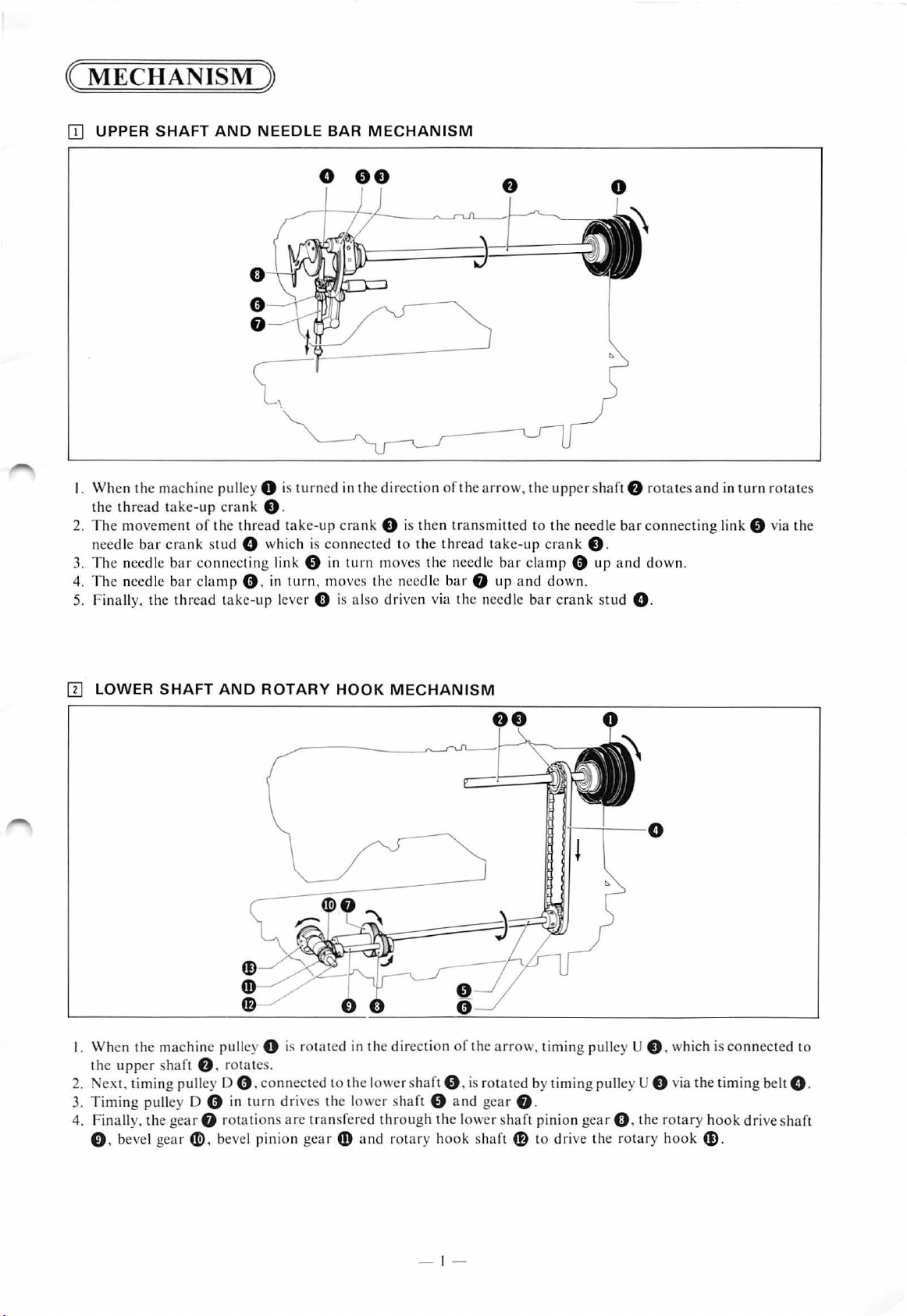
I.
When the machine pulley 0 is turned in the direction
the thread take-up crank
2. The movement
needle
3.
The needle
4. The needle b
5.
Finally, the
SHAFT
bar
crank stud 0 which
AND
of
the thread take-up crank e is then
bar
connecting link 0 in tu rn moves the n
ar
cla
thr
ead take-up lever 0 is also driven v
mp
~
NEEDL
e.
0 ,
E BAR
o
oe
is
connected to the
in
turn
. moves the needle bar
MECHANISM
oft
he
arrow,
the
upper
tr
ansmitted to the needle
thr
ead
ee
dle bar cla
f)
ia
the needle
take-up
up
crank
mp
and
down.
bar
crank stud 0 .
shaft
e.
0 up
f)
rotates and
bar
connecting link 0 via the
and
down.
in
turn
rotate
s
IT]
LOWER
I. When the machine pulley 0 is rota ted in the direction
the
2.
ext. timing pulley D 0 . connected to the lower shaft 0 , is rotated by timing pulley U e via the timing belt 0 .
3.
Timing pulley D 0 in turn dri ves the lower sha
4.
Finally,
e. be
upper
the gear
ve
SHAFT
sha
ft f). rotates.
l gear
4]!)
AND
ROTARY
f)
rotations arc transfered
, bevel pinion gea r
HOOK
4D
MECHANISM
ft
0 a nd gear
through
and rotary hook sha
the lower
of
the
ar
row, timing pulley U e, w
f)
.
shaf
ft
t pinion
41}
gear(). the rotary h
to dri
ve
the rotary h
hi
ch is connecte d to
ook
ook
G)
.
drive shaft
- 1 -
Page 4
IIJ
ZIG-ZAG
MECHANISM
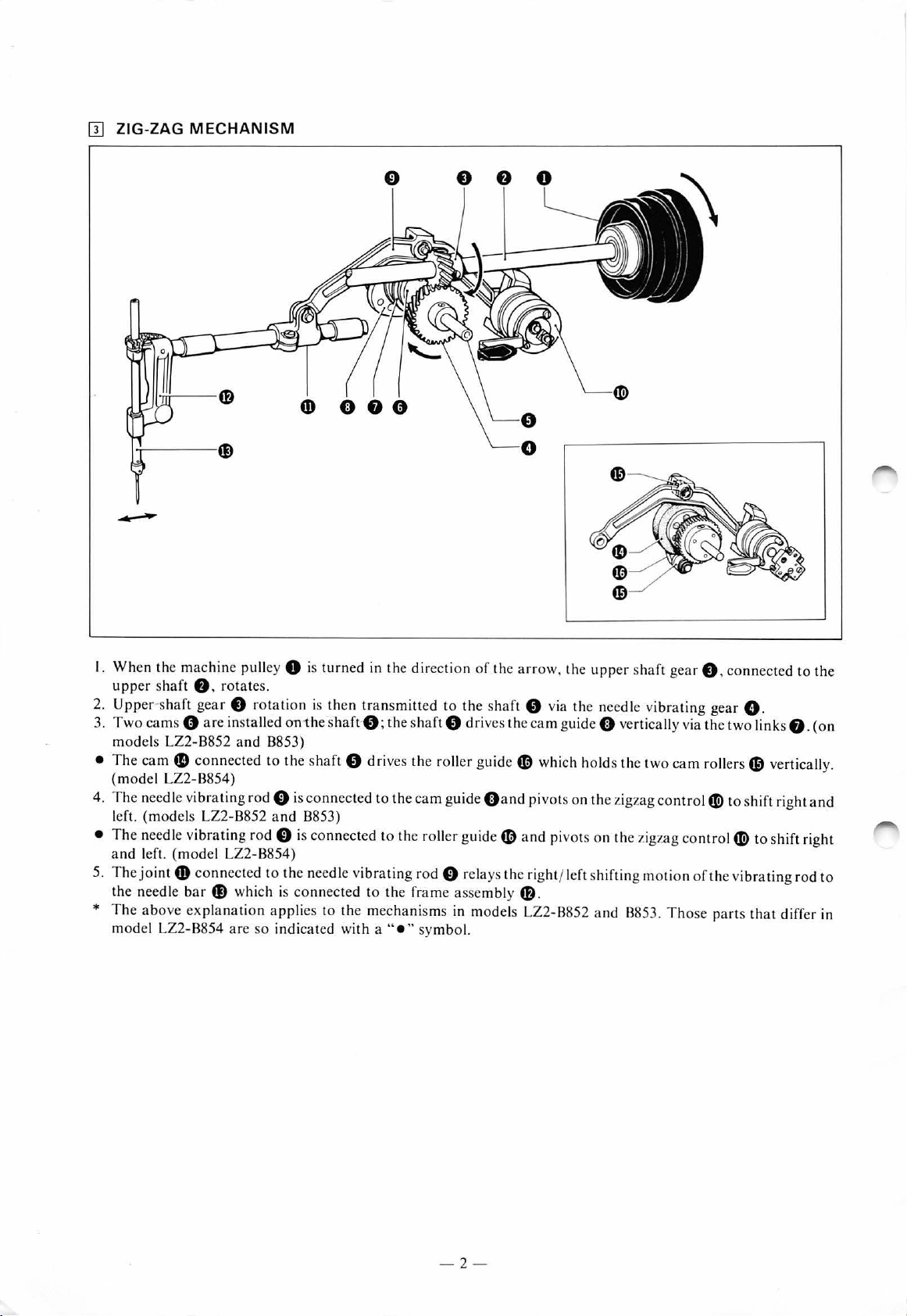
I. When the machine pull
upp
er sha
ft
8 ,
Upp
er s
haft
2.
3. T wo cams 0 are installed oni he s
mod
els LZ2-B8
• The cam
(mod
el LZ2-B854)
4. The needle v
left. (models LZ
• The needle v
a
nd
left. (model LZ2-88
5. The joint
th
e needle bar
*
Th
e a bove explanation a pplies to the mec hanisms
model
gea r 0 rotatio n is
52 and
fD
connected to the s
ibr
ating
ibrating
4D
connecte
4J)
LZ
2-8854
ey
0 is
turn
ed in the
rot
ates.
th
en
transmitt
haft
-8 ;
8853)
haft 8 drive
ro
d 0 is c
2-8852 and
rod 0 is
d to the needle v
whi ch is connected to the fra me asse mbly
are
so
8853)
54)
indic
onn
ected to
connec
ted
ibr
ated with a
direction
ed to the sha
th
e shaft 8
s the roller
the
cam
to the roller
ating rod 0 relays the right
"e
" sy
of the arrow,
ft
8 via
dri
ves the cam guid
guide~
guid
e O a
g
uide~
in models LZ2-B852 and 8853. Those
mbol.
whi ch hol
nd pivo
a nd pivots on the zigzag
f)
.
the upper s
the need
e 0 verti
ds
the t
ts on
the
zigzag
jlc
ft shifting moti
haft gea
le v
ibr
ating gear G.
cally via the t
wo cam
control
control
on
r 0 ,
connected to the
wo
links
rollers G) verticall
G>
to s
hif
t right and
G>
to shift right
of the v
par
ibrating r
ts that
differ in
f).
od
(
on
y.
to
- 2 -
Page 5
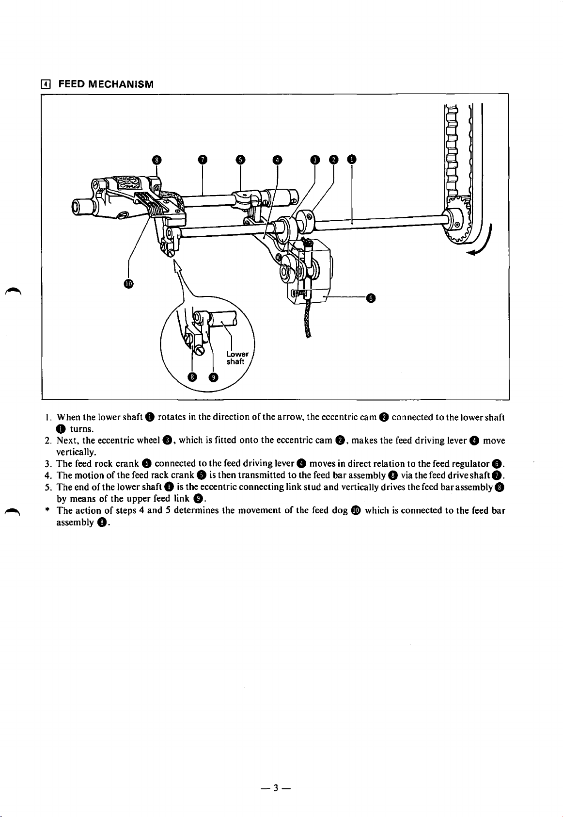
[II FEED
MECHANISM
I. When the lower shaft 0 rotates in the direction
0 turns.
2.
Next, the eccentric
vertically.
3.
The
feed rock
4. The motion
5·.
The end
by means
*
The
assembly
of
the lower shaft 0
of
action
of
0.
of
wheel8,
crank
8 connected to the feed driving lever 8 moves in direct relation
the feed rack crank 8
the upper feed link
steps 4 and 5 determines the movement
which
is
fitted
onto
is
then transmitted
is
the eccentric connecting link stud and vertically drives the feed bar assembly 8
8.
of
the arrow, the eccentric cam 8 connected to the lower shaft
the eccentric cam
to
the feed
of
the feed dog
8,
makes the feed driving lever 8 move
to
the feed regulator
bar
assembly 0 via the feed drive shaft
I)
which
is
connected
to
the feed
8.
8.
bar
-3-
Page 6
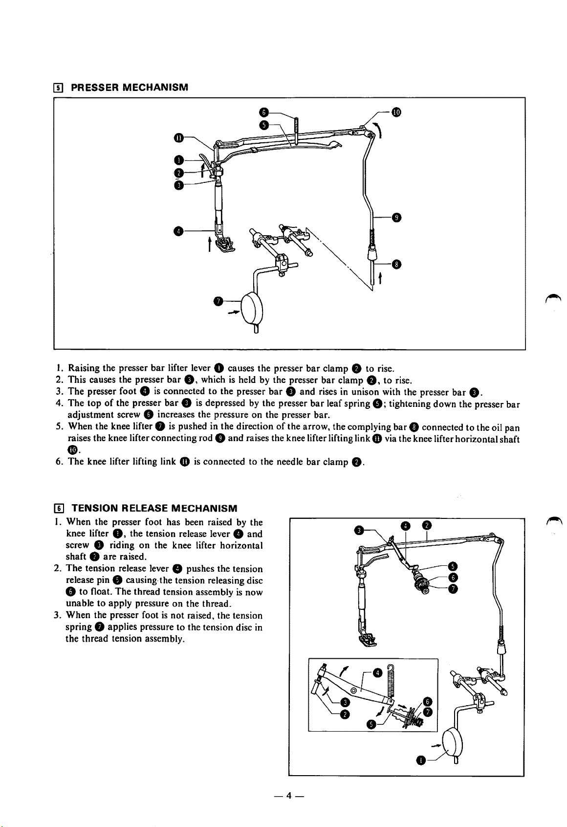
[!]
PRESSER
MECHANISM
•
I. Raising the presser
2. This causes the presser
3.
The
presser foot 8
4.
The
top
of
the presser
adjustment screw 8 increases the pressure on the presser bar.
5. When the knee lifter 8
raises the knee lifter connecting rod 0 and raises the knee lifter lifting link e via the knee lifter horizontal shaft
••
6. The knee lifter lifting link e
[!]
TENSION RELEASE
I. When the presser foot has been raised by the
knee lifter
screw 8 riding on the knee lifter horizontal
shaft 8
2.
The
release pin 8 causing-the tension releasing disc
0,
are
raised.
tension release lever 8 pushes the tension
8 to float. The thread tension assembly
unable
3. When the presser foot
spring 8 applies pressure to the tension disc
the thread tension assembly.
to
apply pressure on the thread.
bar
lifter lever 0 causes the presser
bar
8,
which
is
held by the presser
is
connected
bar 8 is
is
pushed in the direction
MECHANISM
the tension release lever 8 and
is
not raised, the tension
to
the presser
depressed by the presser
is
connected to the needle
is
now
in
bar
clamp 0 to rise.
bar
clamp
0,
to rise.
bar
8 and rises
bar
of
the arrow, the complying bar 8 connected to the oil pan
bar
in
unison with the presser
leaf spring
clamp
8;
0.
bar
8.
tightening down the presser
bar
-4-
Page 7
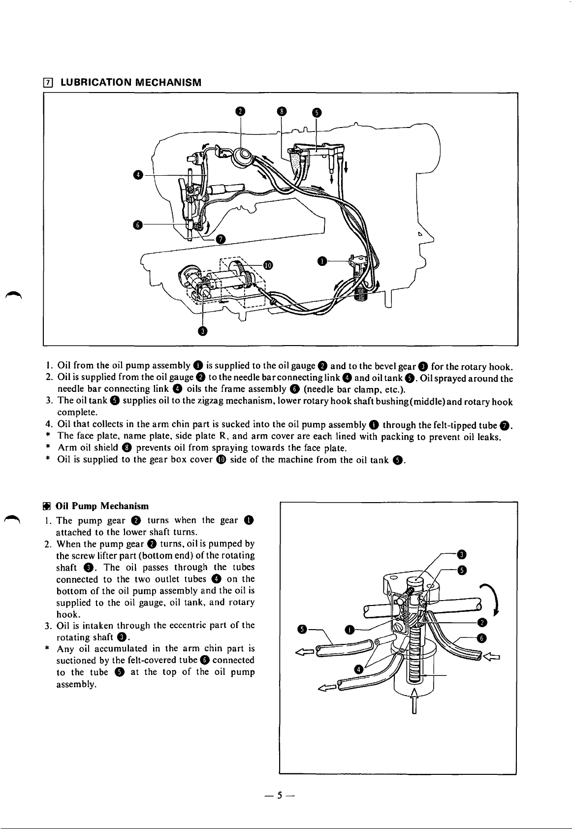
[II LUBRICATION
MECHANISM
I. Oil from the oil
2.
Oil
is
supplied from the oil gauge
bar
needle
3.
The
oil
tank
complete.
Oil
that
4.
*
The
*
Arm
* Oil
collects
face plate, name plate, side plate R,
oil shield 0 prevents oil from spraying towards the face plate.
is
supplied to the gear
pump
assembly 0
connecting link 8 oils the frame assembly 0 (needle
8 supplies oil
in
the
arm
to
chin
box
is
supplied to the oil gauge
f)
to the needle
the zigzag mechanism, lower rotary
part
is
sucked into the oil
cover
CJi)
Ill Oil Pump Mechanism
The
pump
gear
f)
I.
attached
2. When the
the screw lifter
shaft
connected
bottom
supplied to the oil gauge, oil tank,
hook.
3.
Oil
rotating shaft
8.
is
intaken
to
the lower shaft turns.
pump
The
to
the two outlet tubes 8
of
the oil
through
8.
* Any oil accumulated in the
suctioned by the felt-covered tube 0 connected
to
the tube 8
assembly.
turns when the
gear
f)
part
(bottom
oil passes
pump
at
the
turns, oil
end)
through
assembly
the eccentric
arm
top
of
gear
is
pumped by
of
the rotating
the tubes
and
the oil
and
part
chin
the oil
and
side
0
on
the
rotary
of
the
part
pump
f)
and
to the bevel gear 8 for the rotary hook.
bar
connecting link 8
pump
arm
cover are each lined with packing
of
the machine from the oil
is
is
and
bar
clamp, etc.).
hook
shaft bushing (middle)
assembly 0 through the felt-tipped tube
oil
tank
tank
8.
8.
Oil sprayed
to
prevent oil leaks.
and
around
rotary
the
hook
O.
-5-
Page 8
~
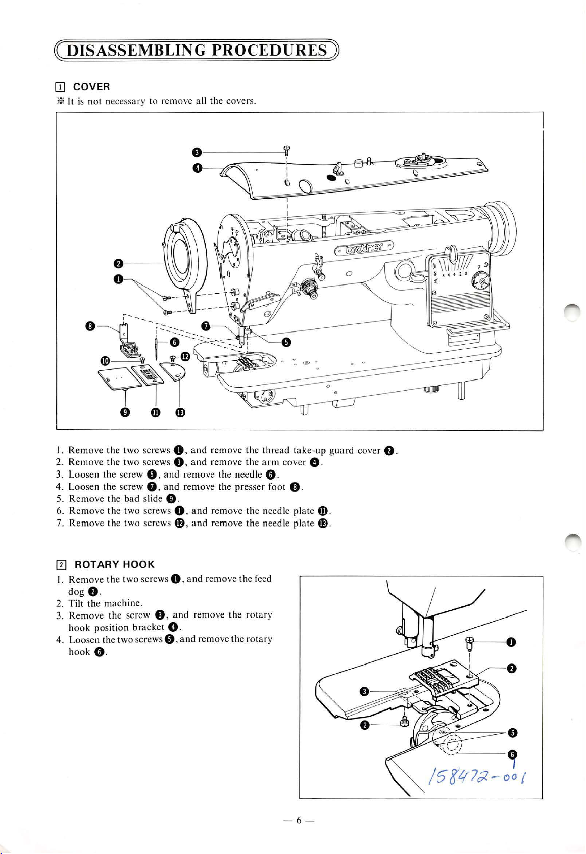
DISASSEMBLING
OJ
COVER
*
It
is n
ot
necessary to remove all the covers.
PROCEDURES
~
I.
Remove
2. Remove
3. L
oose
4. Loose n the screw 8 ,
5. Remove the b
6. Remove
7. Remove the two sc rews
IIJ
ROTARY
I.
Rem
dog
2. Tilt the machine.
3. Remove
h
ook position bracke
4. Loosen the
h
ook
th
e two screws 0 ,
th
e two sc rews 8 ,
n the s
cr
ew 0 ,
ad
slide C).
th
e two screws 0 , and
HOOK
ove the
f).
tw
o screws 0 ,
th
e screw 8 ,
two
scre
0 .
t 0 .
wsO,and
and
remove
and
remove the arm
and
remove the need le 0 .
and
remove the presser fo
remo
ve the need le plate
4D
,
an
d remove
and
remove
and
remove
the
remove the
the
thread
the need
the feed
rot
ary
rotary
take-up
cover
ot ().
le plate
0 .
fD
fD
guard
.
.
cover
f)
.
- 6 -
Page 9
IT]
FEED
MECHANISM
•
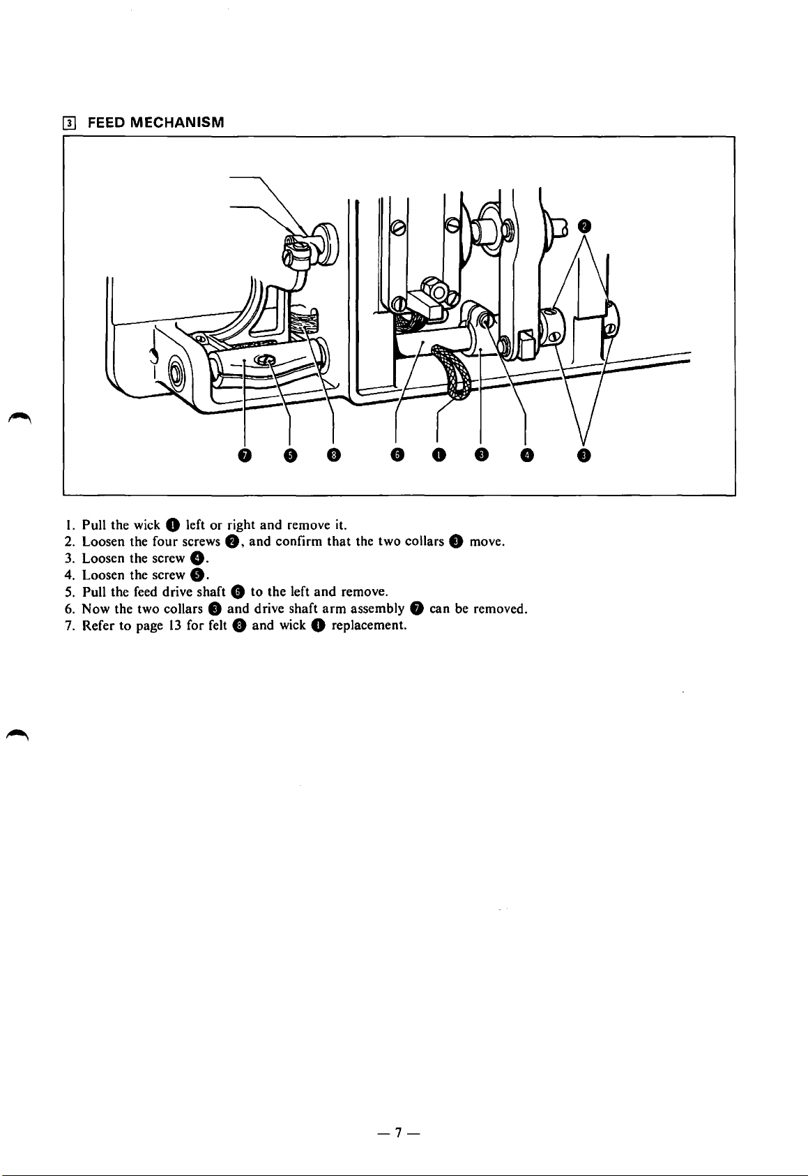
I. Pull the wick 0 left
2. Loosen the four screws
3.
Loosen the screw
4. Loosen the screw
5.
Pull the feed drive shaft 8 to the left
6. Now the two collars
7. Refer to page
or
right
and
8,
and
8.
8.
8
and
drive shaft
13
for felt 0 and wick 0 replacement.
•
remove it.
confirm
and
•
that
remove.
arm
•
the two collars 8 move.
assembly 8 can be removed.
0
•
•
-7-
Page 10

[!]
PRESSER BAR
AND
NEEDLE BAR
• •
• •
•
•
Presser Bar
I. Raise the machine.
2.
Remove the two screws
also be removed.
3.
Remove the eight screws
4. Loosen the work clamp adjustment screw
* Note
5.
6. After removing the screw
*
Needle Bar
7.
8. Loosen the screw
that
if the screw
Loosen the screw
I)
and link
Be
careful not
Remove the screw 8 and remove the needle bar thread guide
assembly.
to
* When the needle
9. Loosen the screw
10.
Loosen the screw fJ, and remove the needle
* Loosen the screws e
connecting link
8 can be removed.
0,
and
remove the thread take-up lever
8,
and remove the face plate
is
loosened
G)
for the presser
together.
1),
remove the presser
lose the presser
e·,
and remove the needle
bar 8 is
f),
and pull pin F
and
fJ
bar
removed, the needle
to
the thread take-up crank
8 until there
too
much the presser bar leaf spring 8 will come out.
bar
clamp
1),
and lower the presser
bar
ball bearing
fD
forward
CD
bar
8 from the top.
bar
clamp
and
bar
frame
8.
The thread take-up mounting disc 8 can
8.
The packing 8 can also be removed.
is
no pressure applied to the presser
bar
0;
remove the presser
0 from the top.
on the
top
of
the presser bar
8.
G)
can be removed.
out.
f).
fl,
and the needle
bar
crank
0.
stud.
bar
and
0.
bar
clamp
needle bar
r-'\
-8-
Page 11

[I]
TIMING
BELT
I. T ilt the
Loosen
2.
3.
Loosen
4. Whi
* Be
5. Take the timin g
6. Raise the
Loo
7.
8.
Take the timing
machin
screw 0 a
screw 0
le depr
ess ing pin 8 wi
carefu
l not
machin
sen the two
e.
nd
remo
and remo
to
lose
the
belt
~
e.
scr
ew
s 0
belt~
ve
the
thr
ee screws
ve the feed regula
th
a screw
pin 8 o r
off
of
and
off of the a
dri
sp
timing
remov
rm.
f)
;
remo
ve
tor stud
ver, remove the length
ring C) .
pulley D
e the machin
e.
4D.
e pulley
the
reverse lever s
cont
ass
embl
y
haft
rol di al ().
G)
.
8 and rev
er
se l
ever
e.
- 9 -
Page 12

~ASSEMBLING
[J]
TIMING
BELT
PROCEDURES )
jj
0
I. Raise the
2.
Mount
3.
Mount
*
Tighten the
machine
4. Tilt the
5.
Mount
6.
Turn
*
Turn
7. Inse rt the s
*
Mount the edge
Mount
8.
screw
9. Mo
mounting
10
. Install th e reverse lever
II. Loo
12. Turn
*
The
machine.
the
timing
the
machine
front
pull
ey, a
mach
ine.
the
timing
the
machine
ing
the
machin
pring 8 and
of
the feed
4D
unt the reverse
sen sc r
the length
reverse lever
regulator
.
screw e.
ew
8 . set the reverse lever
control
belt 0
mounting
djacent
belt 0
pulley G b y
G)
from
pulley G
screw
to
the
onto
e pulley G will
pin 0 .
the
len
gth
stud
shaft
4B
from
shaft
dial
and
s
hould
not
the
hole
onto the
8 ,
the
screw in the
timing
hand, and
mount
and
install the le
control
41)
4B
in link D
the
and
set
move
dial into
reverse lever
the
vertically.
on the t
upp
pull
arm
op
of
er shaft 8 and
screw
found
upper
shaf
ey U 0 .
mount
the
the
timing belt
ngth
the Y-groove
and
feed regula
side, pass it
6)
6)
to the
center
feed length to "0"
(If
it moves, tighten the le
the a
rm
onto
timing
on
the.f
t 8 .
timing
tighten
orwa
belt 0
the
rd si de
0 firml y
control
with
position and retight
of
tor lever D
through
three
(the
dial
C).
the
backstich unit.
feed
set screws
lowest setti ng).
pulley U 0
two
mounting
of the
rotational
onto
timing
onto
and
regulator lever
ngth contr
pulley D 0 .
pulley D
tight
en it in place with
fn
.
en
the screw.
of
the
upper
shaft
8 .
screws
8.
direction
of
the
0.
mounting
U
4J)
an
d secure with
ol dial. Refer to page 16.)
-
10
-
Page 13

11]
PRESSER BAR
AND
NEEDLE BAR
• •
•
• •
•
0
Needle Bar
1.
Mount
2. Push pin
3.
Mount
8 and temporarily tighten set screw
4. Set the zigzag width scale
temporarily tighten set screw
5.
Install the needle
* Before installing the needle
with screws
Presser
6.
Insert the presser
7.
Hook
temporarily tighten set screw
8.
Set
presser
Make the adjustments on the following pages after assembling the machine as above. After adjustments are
completed, install the face plate
and presser plate spring • with two screws
the needle
F 8 all the way in,
the needle
CB
and
Bar
the link
the presser
bar
leaf spring
tD
bar
bar
crank
bar
8 from the top
rod assembly 0 in the
and
temporarily tighten set screw
of
needle
bar
crank rod
arm
chin part.
assembly8;
8.
to
"0". With the needle
bar
8 in the center
8.
bar
thread guide 0 anq set screw 0 onto the needle
bar
above, install the needle
bar
crank
48.
bar
8 into the
hole onto the horizontal shaft
ball bearing 8
fJ
does not come off the presser bar.
arm
1).
onto
fl
and packing
chin
the top
part
and
screw set screw e into the presser
8.
Pass the presser
of
the presser
fD
with eight screws fl. Then install the thread take-up lever e
bar
e.
8.
pass it through the needle
of
the oval hole in the
bar
G.
stud
I)
and
needle
bar
Cl
through the presser
Cl.
Tighten adjustment screw
bar
arm
chin part,
bar
connecting link e
bar
CJ.
bar
clamp
fl
so
clamp
C1
that
and
the
-11-
Page 14

•
Center, front-back,
of
oval hole
·~
Center, left-right,
of oval hole
Adjust the left-right position
I. Install the needle plate and needle.
2. Set the zigzag width scale to "0". (Turn the machine pulley and confirm that the needle tip does not move either
or
right.)
left
*
If
the zigzag width will not assume a
3. Loosen the set screw
centered left and right in the needle hole
4. Firmly tighten set screw
Adjust the front-back position
I. Loosen screw
centered front and back in the needle hole
2.
Make sure there
lightly when the needle zigzags.
3. Firmly tighten set
8;
depress pin F
is
no play in the forward-back direction of the needle bar crank rod assembly and that it moves
screw
of
the needle bar.
"0"
position, refer to page
e and move the needle
of
•.
of
the needle bar.
and/
orR
and move the needle bar crank rod assembly 0 so that the needle tip
of
8.
18
and
bar
crank rod assembly 0 left or right so that the needle tip
the needle plate.
the needle plate.
I
•
7.1
mm
19
for adjustment.
is
is
Adjust the presser foot height
I. Install the presser foot
2. Raise the presser foot • with the presser
3. Place a 7 .I mm thick block gauge under the presser
tighten set screw
When adjustments are completed, install the needle, presser foot and needle plate.
fl.
•.
bar
lifter lever
foot.;
-12-
e.
while pushing the presser
bar
clamp
G)
down, firmly
Page 15

IT]
FEED
I. Tilt the machine.
2.
* Mount the link connected to the feed driving shaft
3.
4. Make sure there
5.
6.
*
7. Adjust the needle and feed timing.
* When the adjustment
8.
9.
MECHANISM
Mount the feed driving shaft 0 from the left side
8,
crank
8,
and collar 8 in that order.
Align the left end
Remove the oil cap 8 and insert the wick 8 through the feed
8 from center
wick
Replace the oil cap
To
replace the felt: loosen the set screw, remove the feed
(I)
On
models LZ2-8852, 8853 and 8854: On 8852, set the mark on the thread take-up lever 8 to the
on the face plate;
(2) After properly positioning the mark on the thread take-up lever
the marks
Set
the feed length regulator to "0
Turn
the machine pulley
of
the feed driving shaft 0 with the
is
no left-right play in the feed driving shaft
of
the feed driving shaft
8.
on
8854, set it
on
the eccentric cam 0
is
ended, firmly retighten the two set screws
and
with the crank 8 positioned where it does not move, firmly tighten fillister screw
to
:E
and
..
, the smallest setting.
of
the
arm
arm 8 on
arm
0.)
; on model 8853, center the mark between the
eccentric wheel
bed, passing it through the feed driving shaft
the end
bed and tighten the set screw 8 for the collar
of
the lower shaft.
0.
drivingshaftO.
bar
hinge pin,
8.
Cf).
(Pull
out
aprox.
and
replace.
~
and
loosen the two set screws
100
CD
mm
~
:~:
marks.
and
fD.
arm
8.
of
the
mark
align
••
10.
Temporarily tighten set screw 8 until the front-back position adjustment
[Model LZ2-B852
·853]
[Model LZ2-B854]
-13-
of
the feed
dog
is
completed.
Page 16

[!]
ROTARY HOOK
Zigzag
width
0 mm
~·
Maximum
zigzag
width
0
0.1
......
0.5
mm
Highest position
~-~~~~.._..
I. Temporarily install the
2.
Temporarily install the rotary
3. Install the needle.
4. Adjust the needle
*
Set
the zigzag width to '"0".
Turn
the machine pulley
Now, align the rotary
between 0
f"V
0.05 mm.
* Set the zigzag width to the
8854.)
Turn
the machine pulley
Loosen needle
hook
point 8
is
aligned with the needle center.
Also, reconfirm
5. Install the feed
6.
Install the needle plate 0 with the two screws
7.
Set
the length control dial
8. Adjust the
bar
and
dog
centering·of the feed
* Loosen set screw e
dog
feed
9. Adjust the feed
Feed
I.
Standard
2.
Loosen the set screw
above the needle plate.
·*
After adjustment, firmly tighten the set screw
Feed
I. When the feed
parallel.
To
To
lowered.
2. When adjusting the feed
90° range from the
* When the feed dog 8 level
dog
* After adjustment, firmly tighten the two set screws
8 does
dog
Dog
Height Adjustment
height when the feed
Dog
Level Adjustment
dog 8 is
prevent puckering,
prevent material from slipping (stitching from skipping), adjust the feed
height.
rotary
and
rotary hook timing.
hook
Then
clamp set screw 8 and vertically shift the needle
top edge
that
the rotary
8 with the two set screws
and
not
strike the needle
height
1),
hook 0 with two screws
hook
position bracket 0 with set screw
(On
model LZ2-B853, set the needle position adjustment lever
and
align the
point
firmly tighten the screw
maximum
and
set the needle to its furthest left position.
of
the
mark
on
the
0 with the needle center,
thread
hook
setting.
to
(5
hole
rotary
mm
in
the needle
hook
8.
thread
take-up lever with the
8.
on
model LZ2-B852,
to
point gap
0.
1).
to
the
maximum
dog
in the needle plate.
adjust the front-back,
and
bias.
dog 8 is
turn
the feed
setting.
and
right-left gaps with the feed driving shaft
plate
0 when the machine pulley
raised
to
its highest position above the needle plate
bar
lifting link hinge pin
between
G).
raised
above
adjust
dog
standard
is
the needle plate,
the feed
dog
bias so
8 level, loosen the two set screws
(reference) position.
adjusted, the feed
standard
that
the front
dog
height will change, making it necessary
CJ.
0"'
0.5 mm
•
•
Ll.O
mm
..
r
~!.?~~~
8.
and
set the needle to rotary
and
8 mm
bar
8.
adjusting the gap between the rotary
0.1
f"V
0.5 mm when the rotary
is
between 0
1),
and
level
is
when the feed dog 8
is
raised.
41.
and
-v
is
turned.
adjust the feed
dog
adjust the feed
Front lowered
''cp''
mark
on
models LZ2-B853
0.05 mm.
dog
and
8 level so
bar
to
the center.)
on
the face plate.
hook
point 8
hook
arm
41
so
is
0.8 mm.
to
a height 0.8
needle plate
that
the front
hinge pin
to
4D
recheck the feed
point
that
with a
•
gap
and
the
mm
are
is
-14-
Page 17

[II
COVER
0 0
I.
Rai
se the
tall the need le pl
2. In s
3. Ins
tall the slide pl
4. Ins
tall
5. In
sta
ll
6. Ins
tall the a
7. Ins
tall
the
the
the
machin
pre
sser
nee
dl
rm
thread
e.
ate
0 with t
ate
0 .
foot
8 w
e 0
with
top
cover 0 with
take-up guard
set
ith
sc
wo scr
set scr
ew
rew 8 .
eig
ht
cover
ews
9 .
screws
4i)
with two
8 .
0.
screws
4)
.
-
15
-
Page 18

~ADJUSTING
PRO.CEDURES
~
[I] NEEDLE BAR POSITION (LEFT
I. Remove the
adjustment.
2.
Set the
3. Loosen set screw 8 from the
4. Adjust the needle
needle
hole in the needle plate.
5.
Firmly retighten set screw
arm
top
cover
zig1.ag
width scale
bar
is
positioned in the center
to
crank rod 8 so
8.
and
..
0".
AND
then make the
top
of
the arm.
of
the needle
[I] NEEDLE BAR POSITION (FRONT
I. Remove the thread take-up guard cover
and
plate
2.
Loosen the two screws
3. Push pin R 8
needle so
hole in the needle plate.
4. Firmly retighten the two screws
* When the adjustment
needle
back, and
smoothly when
then make the adjustment.
8.
and/
or
pin F 0 to adjust the
that
it comes to the center
of
the needle
8.
is
completed make sure the
bar
frame does not move forward and
that
the needle moves easily and
it
zigzags.
that
AND
and
RIGHT)
the
BACK)
face
ADJUSTMENT
~---------------------------------------,
Center, left-right
ADJUSTMENT
~--------------------------------------~
•
0
of
oval hole
[I] STITCH LENGTH
I.
Turn
the length dial 8 clockwise all the way
(in the direction
reverse
reverse lever 8 moves, loosen set screw 0 and
turn
back. Then retighten set screw
any vertical movement
Repeat this operation until the reverse lever 0
will not move when the length control
turned all the way in.
2.
Turn
scale reaches
loosen set screw 8 and adjust the feed carrier 8
bias with the
lever&
the length control
the machine pulley
"0". If the feed scale
crank
* When set screw 8
no movement in the feed regulator shaft
3. Loosen set screw 0 and install the reverse lever
that
it
is
so
Make the following adjustments on models LZ2B852
and
4. Set the length control dial
setting.
5.
Check if the length set
8
and
If the actual
reset the length control
setting and loosen set screw
control dial
and
then retighten set screw
level.
8854.
the actual stitch length are nearly equal.
and
0
just
ADJUSTMENT
ofthe
arrow),
does not move up
dial&
and
make sure the
ordown.lfthe
counter-clockwise
0 and check for
in
the reverse lever
dial&
and
make sure the feed
will
read "0",
8.
is
loosened, make sure there
f).
0 to the maximum
on
the length control dial
set stitch lengths are not equal,
the
dial&
amount
to
the minimum
8.
Turn the length
the lengths differ.
0.
in
8.
is
is
•
-16-
Page 19

It is
possib
l
ever action
s
prin
g h
ook ~ to
!IJ
REFERENCE
* o
adjustm
*
If
adjustments
th
e needle raised.
le
to change
. Rel
ease
adjust.
the
spr
stiffness
ing 0 .
POSITION
ent is needed on model
arc made
with
of the re verse
and
turn the
ADJUSTMENT
LZ2-B854
the need
le in the material. the needle wi
LEVER
because the zi
(NEEDLE
gzag
POSITION)
cam
sets
the
ll
be
bent.
ADJUSTMENT
refere n
ce
position.
Always
make
adjustments
with
[M
odel
LZ2-B852]
* T
urn
off the machine a nd
* Re
mo
ve the
oil
cap
If
the connectin
link s
tud
a
fter
adjustment.
[M
odel LZ2-B853)
* If
th
e need le positi
If
the
needl
I. Set the zig
2.
Set the needle
position.
0 (i.e.
•
If the lin
a
that the needle position
become
th
nd
adjust the needle
s leve
g link s
f)
is
turn
e positio n adju
zag lever
adjustment lever 8 to
Align
the
e lin
es
on the
es are not align
l.
Finall
e.
• L
oose
n set screw
on the l
re
For
turn set screw
For th
turn
*
When the
f
irmly retighten
*
The stopp
scr
Zigzag
I. Remove the
machin
2. L
oosen nut
3. Set
th
the cente
arge
tight
en set scr
the left
e right referen
set screw$ .
ews
0
Width Pos
e.
to
the maxi
at the n
r.
f)
and small b
ew
referen
0 to
adjustment
se
er
4D
shou ld contact the
a
nd~
iti o n
rubb
4!)
.
and turn
mum
eed
le d
rop
confirm
0 a
nd
tu rn the conn
tud
f)
is
turn
ed to the left
on adjustin
sti ng l
to
"0"
refer
ence
large
ed. loosen set screw
pos
y. firml y tig ht e n se t
, and
align the
f)
.
ce
line, l
adjust.
ce
line. l
is
completed.
t screws 0
during
Adjustment
er plug on the b
zigzag width
posi ti on (stitch) com
(counter-cloc
g lever 8 is
eve
.
mark
s on
a nd sma ll bus
iti
on set s
adjustmen
reference
ear
ings. T hen firmly
oose
n screw 0
oose
n
and~
use.
[LZ2-B854]
the ecce
ntr
that
th e mo to r h
ed
to the right (cl
r 8 is
se
a l
bushing
hings).
prin
g 0
t lever e
screw
screw
~
be sure to
.
tip
of
ack
of the
ic shaft
and adju
as com
ecting
lin k s
ockwise), the
kwise), the needle will move to
se
t to the ~ ·
t to the ~ mark (bottom
eve
l
L
0 .
so
lines
and
and
set
6)
.
st
so
es
to
tud
plete
ly sto pped r
f)
to
adjus
needle will
mark
(to p). the need le wi
).
0
- 17 -
t.
the
needle will
unnin
g.
mov
e to
the
lef
t.lfthe connecti
the right. Replace
ll move
move
to the
to
the
00
the
oil
cap
left position.
rig
ht position.
ng
0
Page 20

II]
ZIGZAG
Zigz
ag
* Zi
gzag
* If
adjustments
th
e needle
[
Model LZ2-88
I.
Loosen the set screw
brating leve
vi
desired zigz
set
screw 0 after
2.
The
indicate z
width
WIDTH
Width Adjustm
widt h
adjustment
arc
raised.
52]
r 8
ag
width.
figures in
is 5
igzag
mm.
the
width
[Model LZ2-B853]
I. The
farther left the n
set,
the greater
2. The figures in the
indicate zig
width
is 8
zag
mm.
the zigzag
width
[Model LZ2-B854]
I.
Loosen the set scr
vibra
ting lev
es
ired zi
d
set
screw 0 af
2. The figures in the
indicate zigz
wid
th
is 8
er e up
gzag
ag width
mm.
width.
ter adjus
REFERENCE
ent
s s
hould
made with the n
0 .
and mo
up
and down.
Remember to tig
adjustme
sca
le
on
in mm.
eed
le \·ibra tin g leve r 8 is
sca
le
on
in
mm. Max
ew
0 . and move
or
down. adjusting
Remember to
tment.
sca
le in the
in
mm.
adjusting to
nt.
the
fron
Maximum zigzag
width
the
front
front
Maximum zigng
POSITON
be
made after
eed
le in the
ve
the
hten
t a
rm
becomes.
arm cove r
imum
the needle
tighten the
arm cover
ADJUSTMENT
the
material.
needle
the
the
cover
zigzag
to the
machin
e is st o
the
need le will be bent. A l
e
Zigzag
width
[Model LZ2-
o-
B852) [Model
5mm
pped.
ways
LZ2-B853
o-
make adjust
[Mod
amm
el
) [
LZ2-
B854]
Mode
o- a
ment s
with
l LZ2 -B854)
mm
* If the above
Zigzag Lever Reference Posit ion Adjust me
(
minimum and max
<For
mode
I. Rem
2.
3. L
4.
5.
6. L
7.
*
ove the
Comp
oose
Turn
p
osition
Comp
oosen
Turn
maximum
8854).
Wh
en
retighten
adju
stments cann
imum
ls
LZ2-8
852
nam
e pla te.
letely lower zig
n set screw
set scr
where
let
ely
set scr
set sc
zigzag
the adju
set scr
0 .
ew 8 adjusting the
it does n
rai
se zigzag l
ew
0 .
rew 0 and adju
width (5
stment
ews 0 and
ot
zigz
ag
width a
and
8854>
zag levers
ot vibr
8 and
a te.
evers 8 and
st the needl e to the
mm
on 13852:8
is
completed.
0 .
be
needle
mad
djustm
e.
e.
nt
e.
to
mm
firmly
make th
ent)
a
on
e a
djustm
r-
--=====
ent
8852
below.
;:::===
18 -
========~::===
::=;
~---:;;;;:
0
~1
Page 21

<
For
model LZ2-
I. R
emove the zi
2.
Remove the nam
3. Ali
gn
the
zigzag lever 0 with the
nam
e plate.
4.
Loosen
zigzag
5. Re
6.
M
sid e (ar
7. L
needle
8853).
8. Retighten
zi
If the
following.
I.
Rem
2. Move
3.
Loosen
assemby
move.
4. Retighten set
*
The
adjuste
zi
op
sm
nut
lever 0 a
tight
en
nut
ove the zi
ound
oosen nut ~ and
to
its
nut~
gzag wid
gzag lever
eration , a
oot
th sca le
above adjustment
ove side pl
the
zigz
set
~
stiffn ess in the zi
d with set screw
hly
when the zi
B85
3>
gzag width
e plate.
Q)
and
adjust set
li
gns
Q).
gzag lever
"8"
on the
turn scr
maximum
-
Reinsta
dial.
ate
R.
ag lever
screw
0 wi
nd
6)
ang
le
so that the needle will not
screw
ll
so
that
scale
screw 0 so that the
exactly
0 a
s cannot be m
0 a
6)
.
gzag
not move
the
gzag
with
ll the
name
plate).
ew
tD
zigzag width (8
ll
the
ll the
and
adju
lever 0
fD
.
Adju
during machin
zigzag lever
width
dia l ass
name plate
way
emb
"0"
the
"0".
way
to the left
,
adjus
ting the
ade,
to the right.
st
the
ac
tion can be
st so
that the
on the
mm
0 m
is c ha nged.
ly.
on
a nd
do the
crank
e
oves
[}]
ZIGZAG
I.
Loose
2.
Adju
p
os
ition where the needle
and zi
* The
shaft.
*
After the adjust
screw
se t
REGULATOR
n set
sc
st the
gzag
regul
po
sitio n
O.
rew 0 .
pos
ition contr
ator
control s
ment
POSITION
ol s
tud
bar vibr
0 m
ove lightly.
tud
f)
is a n eccentri c
is completed, firmly tighten
f)
ating r
(FRONT
to the
od
0
AND
BACK)
ADJUSTMENT
0
-
19
-
Page 22

*When
completely stopped before
II]
making
NEEDLE
any
AND
FEED
of
the
standard
making
TIMING
adjustments, always
the adjustments.
ADJUSTMENT
turn
the power
off
and
make sure the
motor
has
[Model LZ2-8852
*
On
model LZ2-B852 set the thread
set it
to
Now make sure the
* If
the
needle
the
~
wheel
8
*
After
the
*
Put
a pointed screw 8 into the P-marked screw
hole
on
screw into the lower shaft screw stop.
·8853]
the
:~
mark;
and
feed timing
or
:~
marks
and
eccentric
adjustment
the eccentric
[Model LZ2-8854]
on
model LZ2-B853, center it between the ~ and
marks
on
the eccentric wheel 8
is
out
on
the face plate.
cam
0.
is
completed, firmly tighten the two set screws
cam
0 and tighten the
take-up
of
leverO
adjustment, first
Then
loosen the two set screws 0
mark
to
the ~ mark
and
eccentric
appropriately
on
the face plate;
:!
marks.
cam 0 on
align the thread
the lower shaft
and
align
0.
•
on
take-up
the
marks
model LZ2-B854,
are
aligned.
leverO
on
mark
the
eccentric
with
----·
[!]
ADJUSTMENT
I.
Loosen the set screw 0 in the upper shaft gear
0
on
the
upper
2.
Adjust the
tip moves in
* Adjust so
small as possible when the needle enters the
needle plate.
firmly retighten set screw
upper
that
OF NEEDLE SIDEWISE
shaft.
shaft
gear
0 so
that
an
inverted
needle sidewise movement
After
"U"
shape.
the adjustment
is
0.
the needle
is
as
completed.
MOVEMENT
[Model LZ2-8852 ·
[Model LZ2-8854]
• •
-20-
8853]
•
within
0.5
Page 23

[!]
NEEDLE
AND
ROTARY HOOK
TIMING
Zigzag width 0 mm
ADJUSTMENT
•
Maximum zigzag
•
0.1
"'0.5
I. Set the zigzag width
2.
Turn
the machine pulley,
this point, the rotary
Also, check
When the rotary hook point
rotary hook point
hook.
Set the zigzag width
3.
B854, set to 8 mm.)
4.
Turn
At this time, check
between
5.
If
the clearance
that
the machine pulley, setting the needle 8
0.1
I'V
* After adjustment, firmly tighten all
I!Ql
PRESSER FOOT HEIGHT
* Make adjustment after turning the power
and
confirming
stopped.
*
Standard
raised by the presser foot lifter 0
I. Raise the presser foot
cover
2.
Place a
foot
3. Loosen the set screw
4. Push the presser
and
height when the presser foot 8
8.
7.1
mm thick object under the presser
8.
screw
in
the set screw G.
* Firmly tighten the set screw G.
to
0 mm.
hook
the clearance between rotary hook point 8
0
and
to
the maximum setting. (On the LZ2-B852 model, set
that
0.5 mm.
is
not correct, loosen the set screw 8
that
the
On
model LZ2-B853 set the needle position adjusting lever
and
adjust the reference line
point 8 should be aligned with the center
0
is
not aligned with the center
needle 8
the clearance between the
motor
is
not within 0
of
the set screws
ADJUSTMENT
has completely
is
7 .I mm.
8 with the knee lifter
8.
bar
position guide 8 down,
width
•
mm
oft
he rotary take-up
and
needle 8
of
the needle,
I'V
0.05 mm, loosen the two set screws
to
the furthest left position.
upper
lip
of
the needle hole and rotary hook point 0
and
adjust by raising
8,
8.
off
is
to
the center.
to
the
"cf>"
mark
on
the face plate. At
of
the needle
is
or
when the clearance between the
to
5 mm; on the LZ2-B853
or
8.
between 0
lowering the needle
8.
I'V
0.05 mm.
and
adjust the rotary
•
•
and
bar
LZ2-
is
8.
Presser Foot Pressure Adjustment
* Presser foot pressure
bar
presser
screwdriver.
spring screw stud 0 with a
is
adjusted by turning the
* Presser foot pressure can be adjusted between 0
rv
9 kg
to
correspond
to
the material being sewn.
-21-
Page 24

[ill SEWING TENSION
Upper Thread
Weaker
* Lower thread tension
* Because the strength
adjustments should be made by the rotary tension
* Note
* The standard operational range
*
*
that
if the pretension 8
Thread
take-up spring
standard strength
a
To
take-up spring
turn
To
spring
slot in the tension stud
the desired strength.
Take-up Spring
15
"-J
25g.
adjust the operational range
the
rotary
change the strength
8.
insert the tip
is
adjusted by turning the thread tension screw
of
the pretension adjustment 8
is
too
weak, the thread would
of
the thread
8
is
a 8
"-J
12
mm. Also, the
of
the thread take-up spring
of
the thread
8.
loosen the set screw 8 and
tension stud bracket.
o'f
the thread take-up
of
a screwdriver into the
8 and turn, adjusting to
is
8.
0.
is
stronger than that
around
the rotary tens10n 8 may shp.
Lower Thread
Stitches
tension is too
Stitches
-
tension is too tight.
ldal seam
-
of
the rotary tension
when
upper thread
loose.
when
upper thread
. .
8.
fine
Weaker
[ffi FEED
Feed
1.
Standard height when the feed dog 0
2.
Loosen the set screw
above the needle plate.
* After adjustment, firmly tighten the set screw
Feed
I. When the feed
parallel.
To
To
lowered.
2.
When adjusting the feed dog 0 level, loosen the two set screws
90° range from the standard (reference) position.
* When the feed
dog
* After adjustment, firmly tighten the two set screws
DOG
HEIGHT
r-~--r;=~~~~----,-r
Dog
Height Adjustment
AND
8.
turn the feed
LEVEL
ADJUSTMENT
Highest position
1
1.0 mm
Highest position
is
raised
to
its highest position above the needle plate
bar
lifting link hinge pin
Lowest position
8.
and adjust the feed dog
Standard
2llllllllllll.a
Front
lowered
~
{j
{j
r-....
~
r---.
'--""
to
8.
Dog
Level Adjustment
dog 0 is
prevent puckering, adjust the feed
prevent material from slipping (stitching from skipping}, adjust the feed dog 0 level so that the front
dog
height.
raised above the needle plate, standard level
dog
bias so
that
the front
is
when the feed dog 0
is
raised.
8.
and adjust the feed
and
bar
hinge pin 8 with a
0 level is adjusted, the feed dog height will change, making it necessary to recheck the feed
8.
~
~
~
~
is
a height
needle plate are
1.0
1.0 mm
mm.
1.0
mm
is
-22-
Page 25

!!!]
ADJUSTMENT
OF ROTARY HOOK
0
.....
0.05
Needle guard
0"'0.5
I
I
I
I
I Fig. 8
mm
Needle
mm
Removal
I.
Turn
the machine pulley, setting the needle
2.
Remove the needle, presser foot, bed slide, bed plate, needle plate, feed dog and bobbin case.
3. Remove the set screw 0
4. Loosen the two hexagon socket set screws
Installation Adjustment
I. Install the rotary hook 8 by loosely screwing in the two hexagon socket set screws
2.
Install the bobbin case stop 8 by loosely screwing in the set screw
3.
After adjusting the needle
hexagon socket set screws
needle will not come
When replacing the rotary hook, always adjust the needle guard position. (Refer to Inset A.)
4. Adjust so that the edge
hook bracket (dotted line)
Make sure the end
bracket (dotted line).
5.
Install the feed dog, needle plate, bed plate, bed slide, presser foot, bobbin case, and needle.
and
remove the bobbin case stop
and
rotary hook timing(refer
8.
Adjust the rotary hook 8 needle guard so
in
contact, thus protecting against rotary hook point damage.
of
the bobbin case stop 8
of
the inner hook. (Refer to Inset
of
the bobbin case stop 8 does not extend to the right beyond the end
to
the highest position.
8.
8,
and remove the rotary hook
to
Section 2
is
installed between 0
of
B.)
8.
8.
0.
the previous page), firmly tighten the two
that
the rotary
t'V
0.5 mm below the end
* Finally, tighten all screws firmly.
[H)
ROTARY HOOK OIL LEVEL
* Loosen the nut
level adjustment screw 8 to regulate the oil
level.
Note: Always check the rotary hook oil level
whenever the rotary hook
While running the machine, place a piece
paper under the rotary hook for approx. 5
seconds. Adjust the oil so
sprayed from the rotary hook forms 2 dotted
lines
on
the paper.
* When oil adjustment
adjustment screw 8 with the nut
0.
and turn the rotary hook oil
is
completed. secure the
ADJUSTMENT
is
changed.
that
the oil being
0.
of
Measuring sheet
'
i
·:i
about
0.8
mm
•
hook
point
and
of
the rotary
of
the rotary, hook
the
-23-
Page 26

[ill
REPLACEMENT
I.
Remove eight
2. Re
move the screw
f).
3.
Adjust
l
insta lling the
4. Loosen the
~
[ill
I.
When the
foot
pushes
e
between
weak.
2.
t
the
eve
r e
1.0
mm with
ADJUSTMENT
lifter
up
pushes
Loosen the
urni
ng the
OF
screws,
clearance between
and
the thread cutt
thread cut
nut 0 and adju
press
or the
the
screw
the
re l
the
upper tens
nut
screw
and next the
0 a
nd then
ter
the scr
ew
OF
THREAD
er foot is lifted
knee
lif
f)
,
and tension
ease
pin, therefore
ion reg
0 a
nd
f)
.
THREAD
the thread cutt
the thread t
er 8 in
f)
.
st
the clea
0 .
up
ter lever,
ulators becomes
adjust
the
CUTTER
face
pla te.
ake-up
case
ra n
ce of0.
TENSION
by the
presser
the shaf
rel
ease
lever
the
ten
tensio
n by
er
of
8
RELEASE
t 0
sion
.---------------
0
0
--
-----------------------,
0
8
[ill
ADJUSTMENT
I.
Push the
2.
Thread
direction
3.
Pre
ss the
*
When
the
ud
0 .
st
*
Loosen
80% of
4.
Adjust
removing
f)
. and
o.
bobb
in fully onto the b
the
mach
of the a
bobbin wind
thread
the
set
screw 0 and
bobbin
the
moving
capac
dri
vin g
the o il
OF
THE
QUANTITY
obbi
n w
ine
as shown
rro
w.
er lever
will not wind evenly
ity.
power of bobbin winding by
cap
e. l
the
bobb
in
L
move th
oose
in
winder driv
the
picture at
f)
onto
.loosen
e bobbin winder lever
ning two
ing
OF
THE
inder spi
the
the
bobbin and
the clampi
screws
wheel
BOBBIN
ndle
0 .
left,
wind
ng sc
WINDING
ing the
run the
rew
L
f)
in
X 0 X
thread onto the
mac
hine.
8 .
and
adjust the height ofthcth
and out.
adjusting
bobbin
so that
seve
the
ral
tim
es in t
read tensio
thread wi
nds
he
n
to
- 24 -
Page 27

~TROUBLESHOOTING
GUIDE)
Trouble
Thread
breaks
Stitches skips
~-----C--au_s_e
Thread
is
thread
take-up.
Improper
Needle incorrectly installed
Thread
is
rotary
hook.
Flaw in the
Needle incorrectly installed
Needle bent. needle tip
crushed
Poor
needle
hook
timing (needle
rotary
height. needle
hook
clearance)
wound
threading
wound
thread
hook.
______
around
around
passage
and
rotary
needle
and
rotary
~l
~~-----I_n_sp_e_c_ti_o_n
the
the
and
bar
Thread
Needle position
Rotary
Rotary hook. bobbin. rotary
take-up. etc.
Needle
Needle
t----------------1
take-up
hook
__
~ll
~------R--em
Remove the
thread.
Install needle in
direction
Remove the
thread.
Clear
replace with a new part.
Install needle in correct
direction
Replace the needle.
Refer
Hook Timing Adjustment".
the
to
"Needle
__
e_d_Y
thread
____
wound-up
correct
wound-up
path.
and
Rotary
~I_P_a_ge~~
or
21
Unever stitches
Thread
loose fighten
breaks
Needle
Rotary
hook
crushed
Presser foot pressure
great.
Improper
Improper
sion
Improper
sion
Improper
spring tension
:'\eedle incorrectly installed
~cedlc
crushed
Improper
hook
Improper
timing timing
Needle
thread
sewn. sewn.
point-bent
feed
dog
lower
upper
thread
bent. :'\cedlc tip
needle
timing
needle
is
too
slender for the Use a needle
or
material being
height
thread
thread
take-up
and
and
or
t----------------1
is
too
ten-
ten-
rotary
feed
Presser foot pressure
Feed
dog
height
thread
take-up
or
movement
tension
Lower
Upper thread tension
Thread
strength
Needle
Needle
~--------------1
~--------------1
t-----------------1
spring
Repair the rotary
point
part.
Refer
sure Adjustment".
Refer
and
Refer
Refer
Refer
Install needle in
direction
Replace the needle.
Referto"Needleand
Hook
Improper
L-----------~-~
thread
or
replace
it
with a new
to
"Presser
to
Bias Adjustment".
to
to
"Sewing Tension".
to
"Sewing Tension".
Timing Adjustment".
or
Foot Pres-
"Feed Dog Height
"Sewing Tension".
correct
Rotary
needle
and
to
suit the
material being
hook
21
feed
Low needle 4uality
t----------------1
-25-
Replace a quality needle.
Page 28

BROTHER
HEAD
HORITA-DORI, MIZUHO-KU. NAGOYA,
CA
TELEX: BROTHER
INDUSTRIES,
OFFICE
: No . 35. 9-CHOME.
BLE
: BROTHER NAGOYA.
4473696J
I 21
201
& J
J(>
lTD.
59743
Prin
JAPAN
ted
in Japan
467
 Loading...