

Brother LZ2-B851, LZ2-B856E, RH-9820 Owner's Manual

INSTRUCTION MANUAL
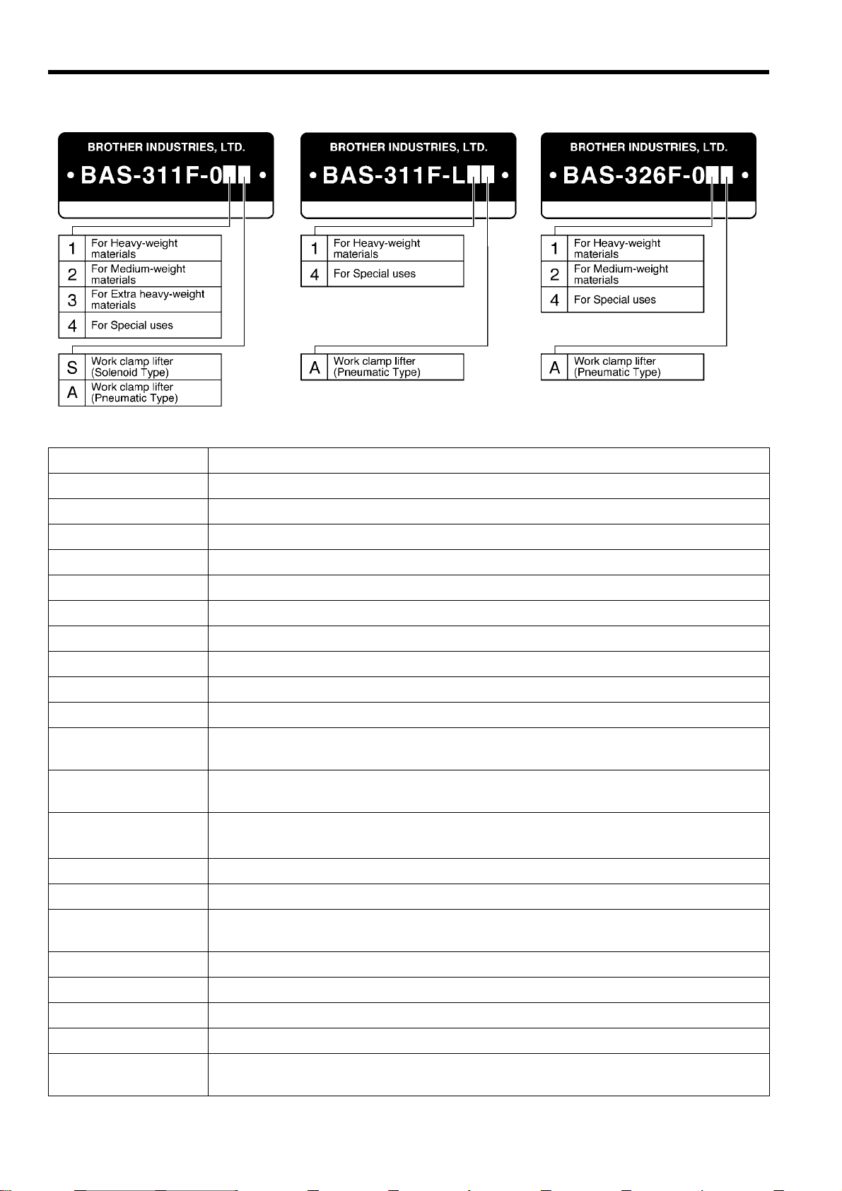
BAS-311F-0, 311F-L
BAS-326F-0
Please read this manual before using the machine.
Please keep this manual within easy reach for quick reference.
PROGRAMMABLE ELECTRONIC PATTERN SEWER

Thank you very much for buying a BROTHER sewing machine. Before using your new machine, please read the safety
instructions below and the explanations given in the instruction manual.
With industrial sewing m achines, it is nor mal to carr y out work while positioned dir ectl y in front of moving parts suc h as
the needle and thread take- up lever, and consequently there is al ways a danger of injury that can be caused by th ese
parts. Follow the instructions from training personnel and instructors regarding safe and correct operation before
operating the machine so that you will know how to use it correctly.
SAFETY INSTRUCTIONS
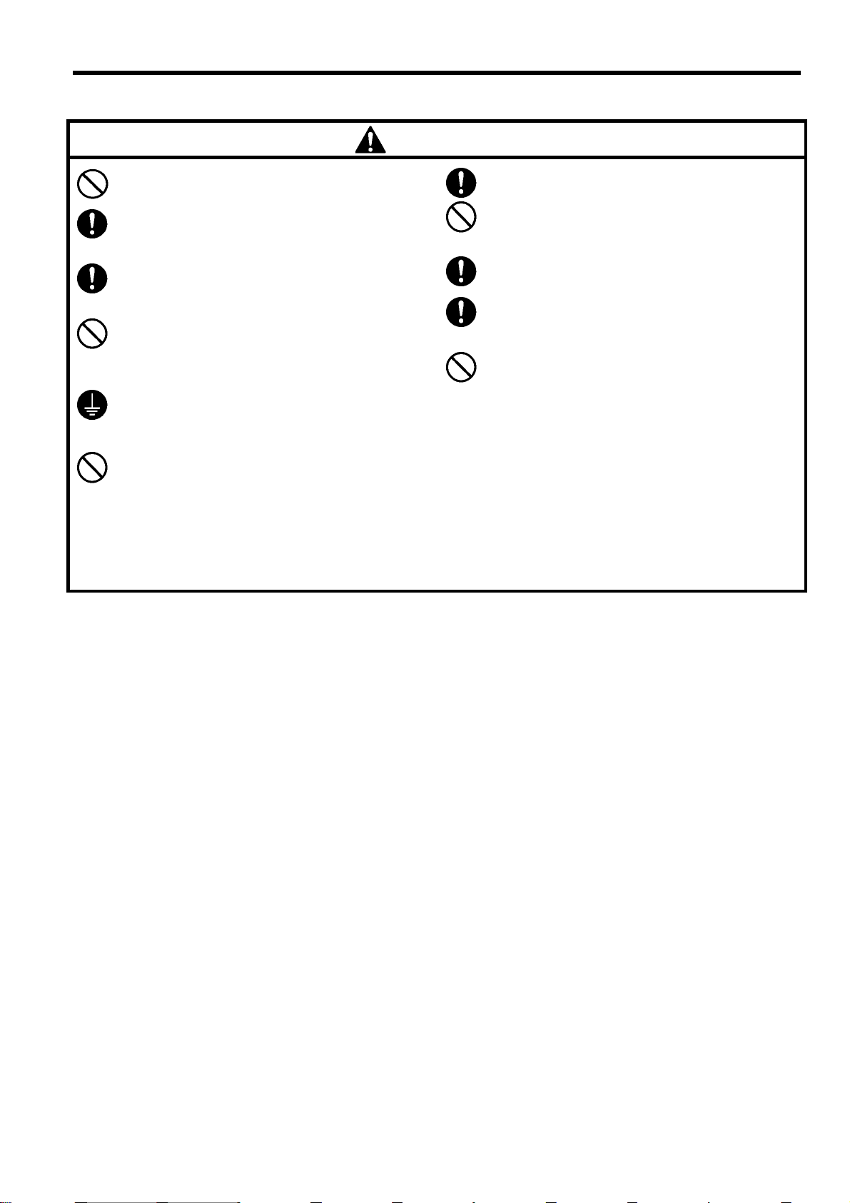
1 Safety indications and their meanings
This instruction m anual and the indications and s ymbols that are used on the m achine itself are provided in order to
ensure safe operation of this m ac hine and to pre vent ac cidents and inj ury to yourself or other people . The m eanings of
these indications and symbols are given below .
Indications
DANGER
CAUTION
Symbols
The instructions which f ollow this term indicate s ituations where fail ure to fol low the
instructions will almost certainly result in death or severe injury.
The instructions which f ollow this term indicate s ituations where fail ure to follo w the
instructions could cause injury when using the machine or physical damage to
equipment and surroundings.
........................................ This symbol ( ) indicates something that you should be careful of. The
picture inside the triang le indicat es the n ature of the caution tha t m ust be
taken.
(For example, the symbol at left means “beware of injury”.)
........................................ This symbol (
........................................ This symbol ( ) indicates something that you mus t do. The pic ture
inside the circle indicates the nature of the thing that must be done.
(For example, the symbol at left means “you must make the ground
connection”.)
) indicates something that you must not do.
BAS-311F-0, 311F-L, 326F-0
i
2 Notes on safety
g
p
p
p
g
g
p
y
p
y
y
p
p
g
y
g
(
p
y
peop
g
pp
g
g
A
y
y
g
y
p
y
g
Wait at least 5 minutes after turning off the power switch and dis connec ti ng the power cord fr om the wa ll outlet
before opening the face plate of the control box. Touching areas where high voltages are present can result in
severe injury.
Environmental requirements
D ANGER
CAUTION
Use the sewing machine in an area which is f ree
from sources of strong electrical noise such as
high-frequency welders.
Sources of stron
problems with correct operation.
Any fluctuations in the power supply voltage
should be within
the machine.
Voltage fluctuations which are greater than this
may cause problems with correct operation.
The
ower supply capacity should be greater
than the requirements for the sewing machine’s
electrical consumption.
Insufficient
problems with correct operation.
neumatic delivery capability should be
The
reater than the requirements for the sewin
machine's total air consumption.
Insufficient
cause problems with correct operation.
electrical noise may cause
10% of the rated voltage f or
ower supply capacity may cause
neumatic delivery capability ma
Installation
Machine installation shou ld on ly be carried out b
a qualified technician.
Contact your Brother dealer or a qualified electrician
for any electrical work that may need to be done.
The sewin
31 1F-0), 70 kg (311F-L, 326 F-0) The installation
should be carried out by two or more people.
Do not connect the
complete, otherwise the machine m ay operate if
the foot switch is depressed by mistake, which
could result in injury .
Hold the machine head with both hands b
more
its original position.
Furthermore, after tiltin
do not push the face plate side or the pulley side
from above, as this could cause the machine
head to to
injury or damage to the machine.
Be sure to connect the
connection is not secure, you run a high r isk of
receivin
with correct operation may also occur.
machine weighs more than 65 kg.
ower cord until installation is
two or
le when tilting it back or retur ning it to
back the machine head,
le over, which may result in personal
round. If the ground
a serious electric shock , and problems
The ambient temperature should be within the
range of 5 to 35
eratures which are lower or higher than this
Tem
may cause problems with correct operation.
The relative hum idit
of 45% to 85% during use, and no dew form ation
should occur in any devices.
Excessivel
formation may cause problems with correct
operation.
Avoid exposure to direct sunlight during use.
Ex
osure to direct sunlight may cause problems
with correct operation.
In the event of an electrical storm, turn off the
ower and disconnect the power cord from the
wall outlet.
htning may cause problems with correct
Li
operation.
ll cords should be secured at least 25 mm awa
from any moving parts. Furthermore, do not
excessively bend the cords or secure them too
firml
that fire or electric shocks could occur.
Install the belt cover and the f ram e side cover to
the machine head and motor.
If usin
casters should be secured in such a wa
they cannot move.
Be sure to wear
when handling the lubricating oil and grease, so
that the
skin, otherwise inflammation can result.
Furthermore, do not drink the oil or eat the
rease under any circumstances, as they can
cause vomiting and diarrhoea.
Keep the oil out of the reach of children.
dry or humid environments and dew
with staples, otherwise there is the danger
a work table which has casters, the
do not get into your eyes or onto your
during use.
should be within the range
so that
rotective goggles and gloves
ii
BAS-311F-0, 311F-L, 326F-0
CAUTION
g
y
p
g
p
y
p
p
y op
y
A
g
y
y
y
p
y
p
p
g
y
g
g
Sewing
This sewing machine should only be used by
operators who have received the necessary
training in safe use beforehand.
The sewin
applications other than sewing.
Be sure to wear
the machine.
If goggles are not worn, there is the danger that if
a needle breaks ,
enter your eyes and injury may result.
Set the needle to the needle u
before turning off the power.
If this is not done, the wi
which might cause the needle to break.
Turn off the power switch at the follo wing times,
otherwise the machine ma
switch is depressed by mistake, which could
result in injury.
When replacing bobbin
When not using the machine and when
leaving the machine unattended
machine should not be used for an
rotective goggles when usin
arts of the broken needle ma
stop position
er may strike the needle,
erate if the foot
Cleaning
Turn off the power switch before carrying out
cleanin
the foot switch is depressed by mistake, which
could result in injury .
Wait until the motor has cooled down before
cleaning the air holes.
The motor ma
been used, and it may cause burns if touched.
, otherwise the machine may operate if
be hot immediately after it has
If using a work table which has casters, the
casters should be secured in such a wa
they cannot move.
ttach all safety devices before using the sewin
machine. If the machine is used without these
devices attached, injury may result.
Do not touch an
objects against the machine while se wing, as this
result in personal injury or damage to the
ma
machine.
If an error occurs in machine o
noises or smells are noticed, immediatel
ower switch. Then contact your nearest Brother
dealer or a qualified technician.
If the machine de velo
nearest Brother dealer or a qualified technician.
Be sure to wear protective goggles and gloves
when handlin
that they do not get into your eyes or onto your
skin, otherwise inflammation can result.
Furthermore, do not drink the oil or eat the
under any circumstances, as they can cause
vomiting and diarrhoea.
Keep the oil out of the reach of children.
of the moving parts or press an
eration, or if abnormal
s a problem, contact your
the lubricating oil and grease, so
so that
turn off the
rease
Maintenace and inspection
Maintenance and inspection of the sewing
machine should only be carrie d out by a qu alif ied
technician.
Ask your Brother dealer or a qualified el ectrician
to carry out any maintenance and inspection of
the electrical system.
Turn off the power switch and disconnect the
power cord from the wall outlet at the following
times, otherwise the mac hine may operate if the
foot switch is depress ed by mistake, whic h could
result in injury.
When carrying out inspecti on, adjus tment and
maintenance
When replacing consumable parts such as the
rotary hook
Disconnect the air hoses from the air supply and
wait for the needle on the pressure gauge to drop
to “0” before carrying out inspection, adj ustment
and repair of any parts whic h use the pneum atic
equipment.
If the power switch and air need to be left on when
carrying out some adjustment, be extremely
careful to observe all safety precautions.
Hold the machine head with both hands by two or
more people when tilting i t back or returning it to
its original position.
Furthermore, after tilting back the machine head,
do not push the face plate side or the pulle y side
from above, as this could cause the machine head
to topple over, which may result in pers onal injur y
or damage to the machine.
Use only the proper repl ac em ent parts as
specified by Brother.
If any safety devices have been removed, be
absolutely sure to re-install them to their original
positions and check that they operate correctly
before using the machine.
Any problems in machine oper ation which result
from unauthorized modifications to the machine
will not be covered by the warranty.
BAS-311F-0, 311F-L, 326F-0
iii
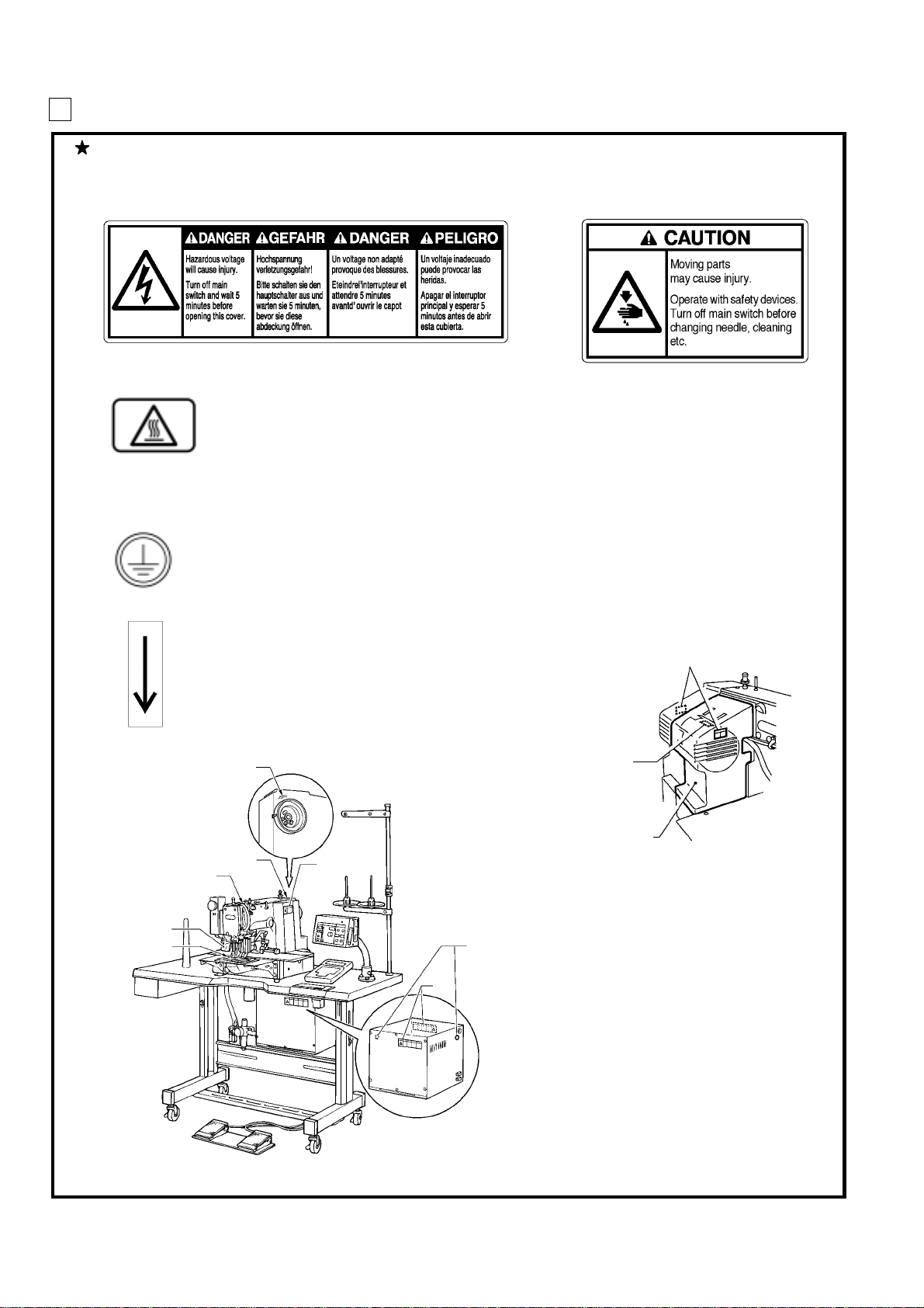
3 Warning labels
4
f
The following warning labels appear on the sewing machine.
Please follow the inst ruc tions on the lab els at all times when using the machine. If the labels ha ve b een r emoved
or are difficult to read, please contact your nearest Brother dealer.
1
3
High temperature warning display
Be sure to connect the ground. If the ground connection is not secure, you run a high risk o
receiving a serious electric shock, and problems with correct operation may also occur.
2
Safety device s
Eye guard
Finger guard
Thread take-up cover
Belt cover
Frame side cover, etc.
5
Direction of operation
Belt cover
Thread take-up cover
Eye guard
Finger guard
1293S
5
Frame side cover
3
1156S
iv
BAS-311F-0, 311F-L, 326F-0

CONTENTS
1. NAME OF MAJOR PARTS ..........................................................................................................1
2. SPECIFICATIONS ...................................................................................................................................2
3. INSTALLATION ...........................................................................................................................................3
3-1. Table processing diagram ...............................................................................................................................................4
3-2. Positioning ..........................................................................................................................................................................4
3-3. Installing the control box ..................................................................................................................................................5
3-4. Installing the rubber cushions ........................................................................................................................................6
3-5. Installing the oil pan ..........................................................................................................................................................6
3-6. Installing the cushions ......................................................................................................................................................7
3-7. Installing the switching plate ...........................................................................................................................................7
3-8. Installing the machine head ............................................................................................................................................8
3-9. Tilting the sewing machine head ...................................................................................................................................9
3-10. Connecting the ground wire .......................................................................................................................................11
3-1 1. Connecting the cords (Installing the operation panel) ..........................................................................................11
3-12. Installing the belt cover ................................................................................................................................................14
3-13. Installing the foot switch ...........................................................................................................................................14
3-14. Installing the spool stand .............................................................................................................................................14
3-15. Installing the eye guard ...............................................................................................................................................15
3-16. Installing the programmer (option) ............................................................................................................................16
3-17. Installing the w or k clamp li fter conne ctin g rod (BAS-311F-0 solenoid type only) .................................. 16
3-18. Installing the feed base cover supports (BAS-311F -L, 326F-0) .........................................................................17
3-19. Installing the X feed base cover (BAS-311F-L, 326F-0) ...................................................................................17
3-20. Connecting the tubes (pneumatic type only) ..........................................................................................................18
3-20-1. Installing the air unit...................................................................................................................................................19
3-20-2. Adjusting the speed controller ................................................................................................................................19
4. LUBRICATION..............................................................................................................................................20
5. CORRECT OPERA TION.................................................................................................................21
5-1. Selecting the needle and thread ..................................................................................................................................21
5-2. Installing the needle ........................................................................................................................................................21
5-3. Threading the upper thread ..........................................................................................................................................22
5-4. Winding the lower thread ..............................................................................................................................................23
5-5. Replacing the bobbin case and threading the thread .............................................................................................24
5-6. Sewing conditions and thread tension .......................................................................................................................24
5-6-1. Sewing conditions .....................................................................................................................................................24
5-6-2. Lower thread tension ................................................................................................................................................25
5-6-3. Upper thread tension ................................................................................................................................................25
5-6-4. Thread take-up spring height ...................................................................................................................................25
5-6-5. Thread take-up spring tension ..................................................................................................................................25
5-6-6. Adjusting arm thread guide R....................................................................................................................................25
6. USING THE OPERA TION PANEL....................................................................................26
6-1. Explanation of panel .......................................................................................................................................................26
6-2. Using the floppy disk ......................................................................................................................................................28
6-3. Using the program R/W (Read/Write) switch ...........................................................................................................30
6-4. Using the TEST switch (Checking the sewing pattern) ..........................................................................................31
6-5. Using the emergency stop switch ...............................................................................................................................32
6-6. Adjusting the sewing SPEED control .......................................................................................................................33
6-7. Changing the X-SCALE and Y-SCALE settings ......................................................................................................33
BAS-311F-0, 311F-L, 326F-0

6-8. Using the bobbin thread counter .................................................................................................................................34
6-9. Using production counter ..............................................................................................................................................35
6-10. Using single split mode ...............................................................................................................................................36
6-11. Shifting a stitch pattern ................................................................................................................................................37
7. SEWING ...............................................................................................................................................................38
7-1. Before starting sewing....................................................................................................................................................38
7-2. Sewing operation ............................................................................................................................................................38
8. CLEANING AND INSPECTION .........................................................................................40
8-1. Cleaning the rotary hook ...............................................................................................................................................40
8-2. Lubrication ........................................................................................................................................................................40
8-3. Draining the oil ................................................................................................................................................................40
8-4. Cleaning the control box air inlet port .........................................................................................................................41
8-5. Cleaning the air holes of belt cover and frame side cover ....................................................................................41
8-6. Cleaning the eye guard .................................................................................................................................................41
8-7. Checking the needle ......................................................................................................................................................41
9. STANDARD ADJUSTMENTS ...............................................................................................42
9-1. Adjusting the needle bar height....................................................................................................................................42
9-2. Adjusting the needle bar lift amount ...........................................................................................................................42
9-3. Adjusting the needle clearance ...................................................................................................................................43
9-4. Adjusting the driver needle guard ...............................................................................................................................43
9-5. Adjusting the shuttle race thread guide .....................................................................................................................43
9-6. Adjusting the movable knife .........................................................................................................................................44
9-7. Adjusting the presser foot..............................................................................................................................................46
9-8. Changing the presser foot lift .......................................................................................................................................47
9-9. Adjusting the wiper .........................................................................................................................................................48
9-10. Adjusting the two-step work clamp lift amount .......................................................................................................49
9-10-1. BAS-311F-0 Solenoid type ....................................................................................................................................49
9-10-2. BAS-311F-0, 311F-L Pneumatic type ....................................................................................................................49
9-10-3. BAS-326F-0 ............................................................................................................................................................50
9-10-4. Adjusting the air pressure ......................................................................................................................................50
9-1 1. Adjusting the nee dle up s top position ......................................................................................................................51
9-12. Checking the input sensor and DIP sw itch input ...................................................................................................52
9-13. Checking the input voltage .........................................................................................................................................53
9-14. Clearing all memory settings .....................................................................................................................................53
10. DIP SWITCH ..............................................................................................................................................54
10-1. Panel DIP switch functions .........................................................................................................................................54
10-2. DIP swtiches inside the control box ..........................................................................................................................56
11. CHANGING SPECIAL FUNCTIONS AND
USING THE MEMORY SWITCHES
........................................................................58
12. ERROR CODES .....................................................................................................................................63
13. GAUGE PARTS LIST ACCORDING TO SUBCLASSES .............66
14. TROUBLESHOOTING .................................................................................................................68
15. OPTIONS ........................................................................................................................................................72
BAS-311F-0, 311F-L, 326F-0
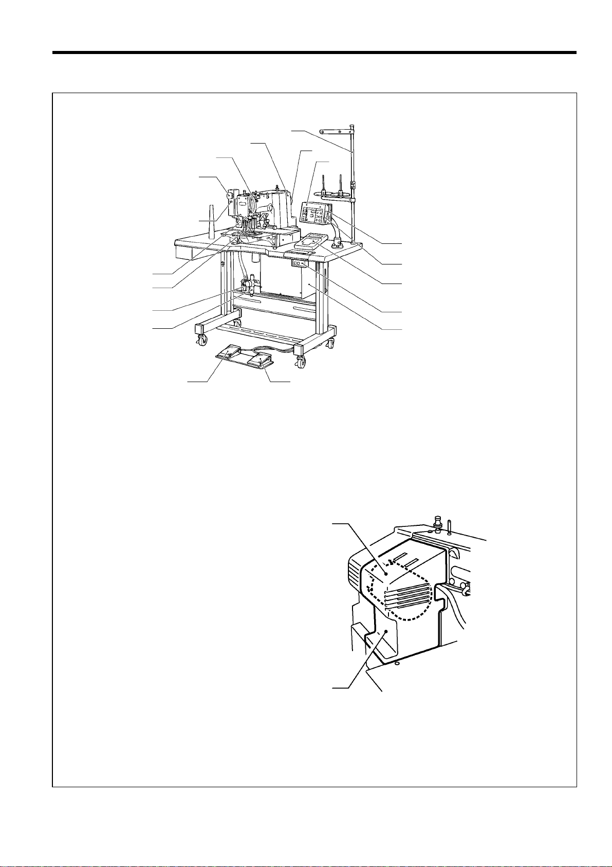
1. NAME OF MAJOR PARTS
(8)
(12)
(1 1)
(16)
(17)
(10)
(9)
(7)
(3)
1. NAME OF MAJOR PARTS
(15)
(18)
(14)
(20)
(19)
1157S
(1) Power switch
(2) Control box
(3) Operation panel
(4) Presser lifter pedal
(5) Starting pedal
(6) Motor cover
(7) Pulley
(8) Spool stand
(14) Programmer
(15) Floppy disk drive
(16) Emergency stop swich
(17) Thread wiper switch
(18) Dip switch
(19) Integrater
(20) Solenoid valve
(4)
(1)
(2)
(5)
(6)
Safety devi ce s
(9) Finger guard
(10) Eye guard
(11) Thread take-up cover
(12) Belt cover
(13) Frame side cover
(13)
1159S
BAS-311F-0, 311F-L, 326F-0
1
2. SPECIFICATIONS
2. SPECIFICATIONS
Stitch formation Single needle lock stitch
Sewing machine Lock stitch, pattern tacking sewing machine (with large shuttle hook)
Maximum pattern size BAS-311F-0: 130 X 60 mm, BAS-311F-L: 220 X 60 mm, BAS-326F-0: 220 X 100 mm
Maximum stitch number 20,000 (one pattern)
Stitch length 0.05 - 12.7 mm
Maximum sewing speed 2,500 rpm (When stitch length is 3 mm or less)
Feed mechanism Intermittent feed, pulse motor drive
Rotary hook Shuttle hook (Standard rotary hook is sold separately)
Needle DP X 5, DP X 17, MR
Data storage method 3.5 floppy disk 2HD/1.44MB, 2DD
T est function Operation test function provided for use with low speed drive
Safety devi ce s
Work clamp height
2-step work clamp
Work clamp lift stroke 18 mm
Automatic stop function for activation in the event of misoperation realized with intermediate
stop function and safety circuits
BAS-311F-0:For solenoid - Max. 17 mm, for pneumatic - Max. 30 mm
BAS-311F-L, BAS-326F-0:Max. 30 mm
BAS-311F-0:For solenoid - unit work clamp, for pneumatic - separate work clamp
BAS-311F-L, BAS-326F-0:Separate work clamp
Intermittent stroke 0 or 3 (Factory default) - 8 mm
Weights
Power supply Single-phase 110V, 220V, 240V, 3-phase 220V, 380V, 400V, 600V A
Motor Three-phase 400 W induction motor
Air pressure 0.50 MPa 1.8 l/ min
Power table T-shaped for use sitting or standing
Machine dimensions
2
Machine head BAS-311F-0: 65kg, BAS-311F-L, BAS-326F-0: 70kg
Control box: 10 - 20 kg (depending on destination)
1,200W X 590 D X 1,120 H mm (Sitting)
1,350 H mm (Standing) …..Excluding spool stand
BAS-311F-0, 311F-L, 326F-0
3. INSTALLATION
3. INSTALLATION
CAUTION
Machine installation should onl y be carried out by
a qualified technician.
Contact your Brother dealer or a qualified
electrician for any electrical work that may need to
be done.
The sewing machine head weighs more than 65 kg
(311F-0), 70 kg (311F-L, 326F-0). The installation
should be car ried out by two or more peopl e.
Do not connect the power cor d until installatio n is
complete, otherwise the machine may operate if
the foot switch is depressed by mistake, which
could result in injury.
Be sure to connect the ground. If the ground
connection is not secure, you run the risk of
receiving a serious electric shock.
Hold the machine head with both ha nds by two or
more peple when tilting it b ack or r eturning it to its
original position. Furth er more, after tilting back the
machine head, do not push the face plate side or
the pulley side from above, as this could cause the
machine head to topple over, which may result in
personal injury or damage to the machine.
All cords should be sec ured at least 25 mm awa y
from any moving parts. Furthermore, do not
excessively bend the ca ble or secure it too firm ly
staples, otherwise there is the danger that fire or
electric shocks could occur.
Install the belt cover and the f rame side cover to
the machine head and motor.
If using a work table which has casters, the casters
should be secured in such a way so that they
cannot move.
Be sure to wear protective goggles and gloves
when handling the lubricating oil and grease, so
that they do not get into your eyes or onto your
skin, otherwise inflammation can result.
Furthermore, do not drink the oi l or eat the gr ease
under any circumstances, as they can cause
vomiting and diarrhoea.
keep the oil out of the reach of children.
BAS-311F-0, 311F-L, 326F-0
3
3. INSTALLATION
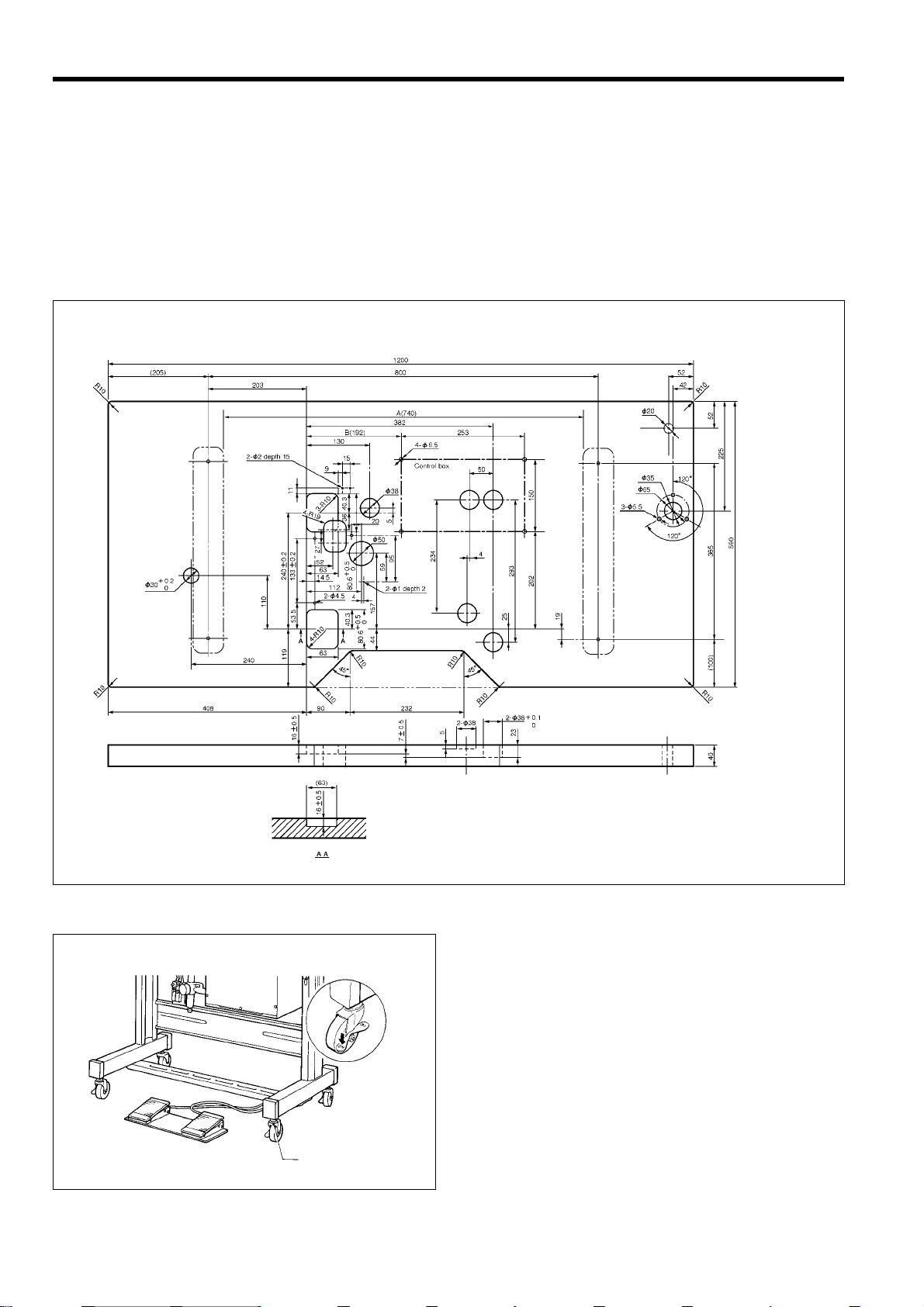
3-1. Table processing diagram
* If using a commercially-available table, process it as shown in the illustration below.
Note
The thickness of the table should b e at least 4 0 mm , and it should be strong enough t o bear the weight
and vibration of the sewing machine.
If the distance A between the insides of the legs is less than 740 mm, move the contro l box installation
position to the left (B=192 mm).
Check that the control box is at leas t 1 0 m m awa y fr om the leg. If the c ontrol b ox and leg ar e touc h ing, it
could cause the sewing machine to operate incorrectly .
[Standard]
3-2. Positioning
4
1290S
Determine the position for the sewing machine, and then
lock the casters (1) so that the sewing machine will not
move.
(1)
1161S
BAS-311F-0, 311F-L, 326F-0
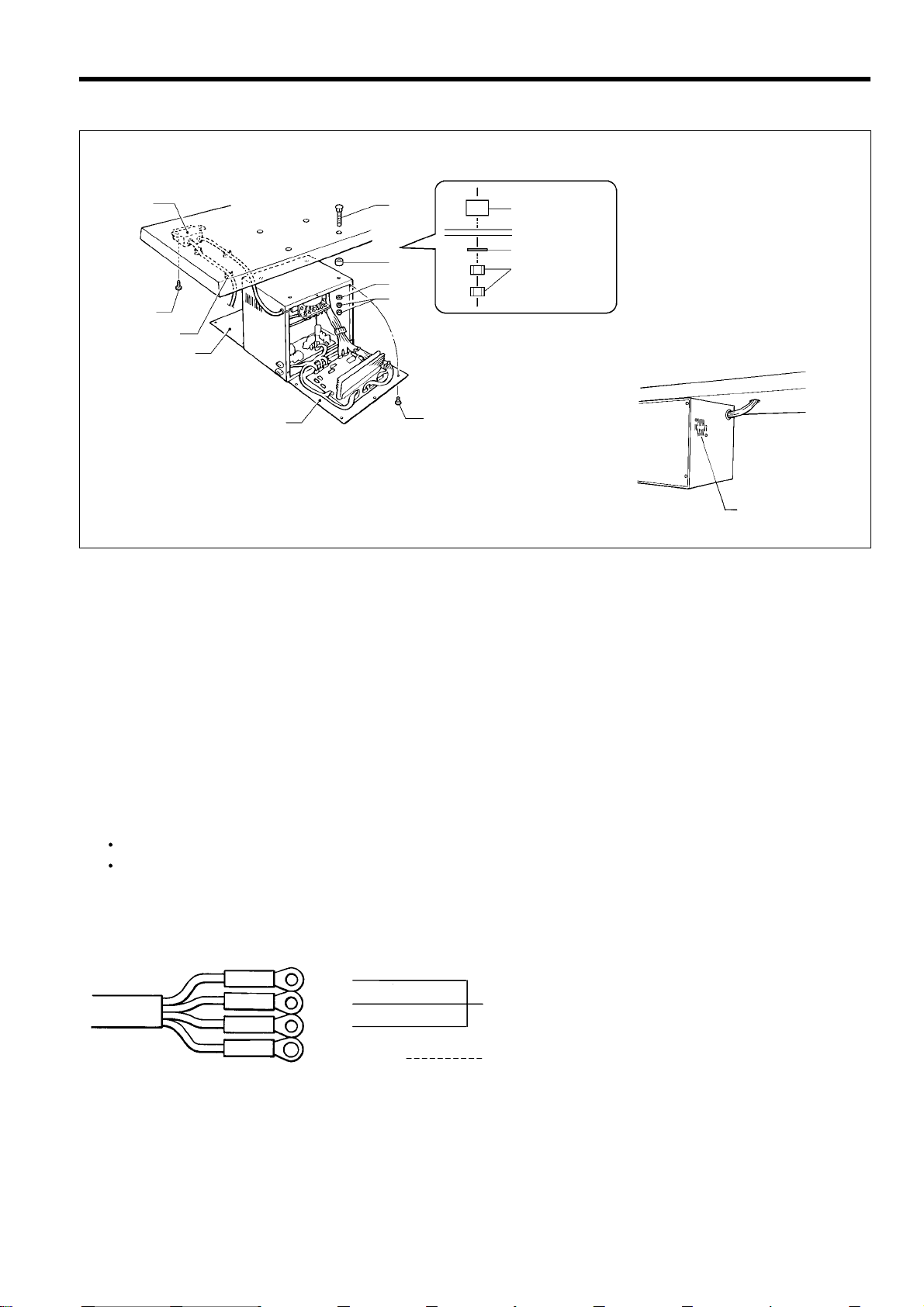
3-3. Installing the control box
/
3. INSTALLATION
(8)
(4)
(5) Sp ace r
(6) Flat washer
(5)
(7) Nut
(6)
(9)
(7)
(10)
(2)
(3)
(1)
(1 1)
1292S1291S
1. Remove the screws (1), and then open the covers (panel mounting assembly (2) and main P.C. board mounting plate
(3)).
Caution: When opening the cover, hold it securely so that it does not fall down.
2. Install the contr ol box with the four acce ssory bolts (4), spacers (5), flat washer s (6) and nuts (7) as shown in t he
illustration above.
* At this time, leave a gap of approximately 1 mm between the work table and the top of the box.
3. Close the covers (panel mounting assem bly (2) and main P.C. b oard mounting plate (3)), and t ighten them with the
screws (1).
* The main P.C. board mounting plate (3) will be opened again during "3-11. Connecting the cords", so provisionally
tighten it with the screw (1).
4. Install the power switch (8) with the two screws (9).
5. Secure the power switch cord with the five staples (10).
Note
Secure the motor cord with staples in such a way that it does not cross over the outlet port of the cooling fan (11)
Some specifications are not s upplied with an access ory power switch (10). For these specif ications, connect a
power switch which satisfies the necessary regulations in the country of use.
Red
White
Black
Y ellow
0064Q
BAS-311F-0, 311F-L, 326F-0
Connect to the power switch. However,
the black wire is insulated to the inside of the
box and is not used.
Connect to ground
5
3. INSTALLATION
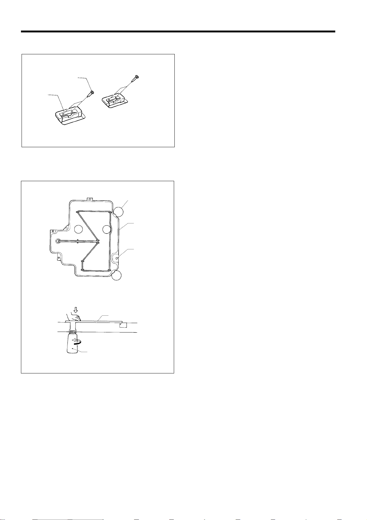
3-4. Installing the rubber cushions
Install the rubber cushions (1) with the nails (2).
* Install so that the head of the nail do es not protrude
(2)
(1)
1296S
from the rubber surface.
3-5. Installing the oil pan
(4)
(2)
(1)
(2)
(3)
0054Q
1. Insert the tabs of the oil pan (2) into the holes f or the
table (1), and then secure it in plac e with t he f iv e na ils
(3) so that the oil pan (2) is not at an angle.
2. While pushing the oil pan (2) down from above, screw
in the oil container (4).
0055Q
6
BAS-311F-0, 311F-L, 326F-0
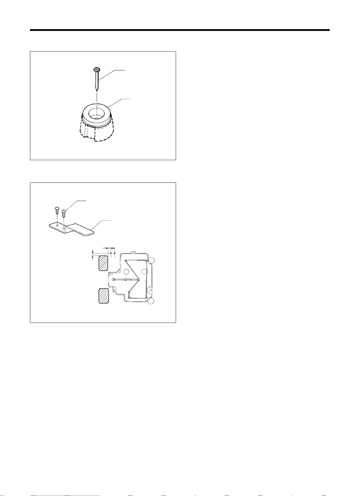
3-6. Installing the cushions
Place the two cushions (1) into the holes in the work table,
and secure them in place with the nails (2).
(2)
(1)
0056Q
* Install so that the head of the nail do es not protrude
3-7. Installing the switc hing plate
Install the switching plate (1) to the work table with the two
wood screws (2) in the position shown in the illustration.
(2)
(1)
* The switching plate and the switch brack et which is
3. INSTALLATION
from the rubber surface.
attached to the machine head prevent the sewing
machine from starting when the machine head is tilted
back. Therefore, this means that the sewing m achine
will not start if the switching plate is not installed.
11
15
9
1162S
BAS-311F-0, 311F-L, 326F-0
7
3. INSTALLATION
3-8. Installing the machine head
1163S
(2)
(5)
(8)
(9)
(1)
(4)
(3)
(5)
(6)
14.5m
133m
13.2m
Fig. 1
1164S 1165S
1. Insert the head h inges (1) into the machine head so tha t they are parallel, and then secure them with the t wo set
screws (2).
2. Place the machine head gently on top of the rubber cushions (3) and cushions (4).
Note
Poll the cords (5) out as shown in the illustration above in order to prevent them from being clamped by the machine
head.
3. Install the hinge presser (6) with the two bolts.
4. Check that the head position switch is turned on as shown in Figure 1.
5. Connect the motor cord connector (8) to the accessory cord connector (9).
8
BAS-311F-0, 311F-L, 326F-0

3. INSTALLATION
3-9. Tilting the sewing machine head
BAS-311F-L, 326F-0 : Remove the X feed base cover (1) and the feed base cover support (3) (below) from the machine
head before tapping the head rest (5) (next page) into the work table.
BAS-311F-L BAS-326F-0
(2)
(1)
1166S 1167S
(1)
(2)
1. Loosen the scr ews (2) which ar e ho lding the X f eed base cover L assembly (1) b y about 2-3 turns , and then rem o ve
the X feed base cover L assembly (1) in the direction of the arrow in the illustration.
Note
The sewing machine is packed without the X feed base cover L assembly (1) installed.
BAS-311F-L
(3)
1168S 1169S
(4)
(3)
BAS-326F-0
(4)
2. Loosen the scr ews (4) which are holding the feed base cover supp ort (3) on the left of the sewing machine (when
looking from the front of the sewing machine) by about 2-3 turns, lift the feed base cover support (3) up slightly (BAS31 1F-L) or down slightly (BAS-326F-0), and then remove it in the direction of the arrow in the illustration.
Note
The sewing machine is packed without the feed base cover support (3) installed.
BAS-311F-0, 311F-L, 326F-0
9

3. INSTALLATION
1170S
(4)
BAS-311F-L
(4)
BAS-326F-0
1171S
3. Move the press er arm as sembly (4) as far as it will go in the direct ion of the arro w in the illustration (to th e left when
looking from the front of the sewing machine).
(5)
(6)
0060Q
1172S
4. Tap the head rest (5) into the table hole.
Note
T ap the head rest (5) securely into the work table as far as it will go.
5. Stand at the left side of the table, and gently tilt the machine towards you. When retur ning th e machine to the original
position, be careful of the shuttle hook cover (6) and the cord.
Note
Be sure to have two or m ore people there when tilting back the machine head and returning it to its original
position.
After tilting back the machine head, do not push the face plate or the pulley from above.
10
BAS-311F-0, 311F-L, 326F-0
3-10. C onnecting the ground wire
/
(4)
CAUTION
Be sure to connect the ground. If the gr ound connection is no t secure, you run the risk of receiving a serious
electric shock.
Connection method for 3-phase power supply
3. INSTALLATION
Red
White
Black
Y ellow
3-phase
power supply
Yellow/Green
Greeen
Connect to
ground
0064Q
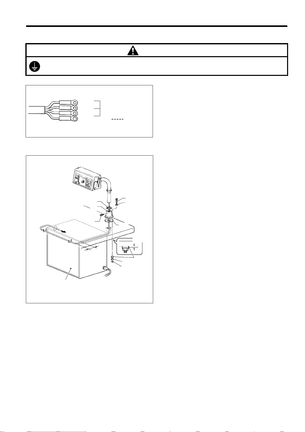
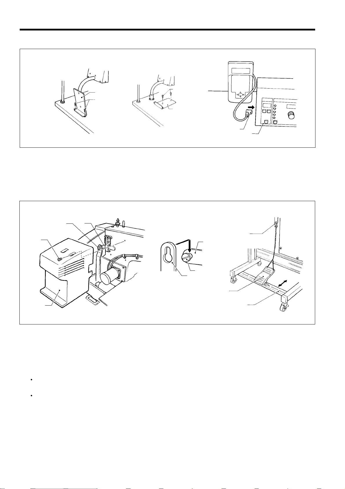
3-11. C onnecting the cords (Installing the operation panel)
1. Assemble the operation panel stand (1) and cushion A
(2). Then insert the bolts (4) together with the washers
(3) into the three hol es from above, and th en tighten
the nuts (5), washers (6) and cushion B (7) from below
to secure the a ssembly.
Note
Tighten until the thickness of cushion B (7)
becomes about 1 mm.
2. Pass the cords of the control pane l assem bly through
the hole in the operation panel stand (1).
3. Attach the rubber sheet (8) to the hole in the operation
panel stand (1) and then secure it with the bolt (9).
4. Insert the cord into th e c ontrol box thro ugh the hole at
the side of the box. Refer to page 13.
5. Secure the cord with the staples ( in two places).
Note
When opening the front cover, check that the code
does not touch it.
Front cover
(8)
(1)
(9)
40 mm
(2)
(6)
(5)
(3)
1 mm
(7)
1587Q
BAS-311F-0, 311F-L, 326F-0
11
3. INSTALLATION
(14)
(17)
(10)
(1 1)
(15)
(19)
(18)
(16)
(13)
A
1173S 1073Q
(12)
1175S
6. Gently tilt back the machine head. Refer to “3-9. Tilting the sewing machine head”.
Note
Be sure to have two or m ore people there when tilting bac k the machine head and re turning it to its original
position.
After tilting back the machine head, do not push the face side or the pulley side from above.
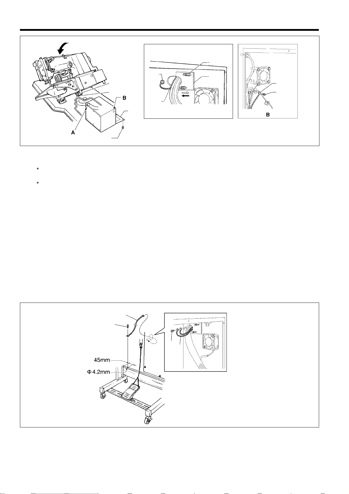
7. Pass the cords (10) through the hole (11) near the hinge of the work table.
Note
If the cords are passed through the wrong hole, they may become damaged.
8. Gently return the machine head to its original position.
9. Remove the screws (12), and then open the control box cover (main P.C. board mounting plate (13)).
Note
When opening the cover, hold it securely so that it dose not fall down.
10.loosen the two screws (14), and then open the cord presser plate (15) in the direction of the white arrow and pass the
cords (10) through the opening.
1 1.Loosen the screw (17), and then connect the ground wire (16) that is coming from the machine head as shown in the
illustration.
12.Remove the screw (18), and then pass it through the term inal hole in the ground c ord (19) fr om upper shaft motor.
Then re-tighten the screw (18) so that the ground cord (19) is secured as shown in the illustration.
Note
Make sure that the ground connections are secure in order to ensure safety.
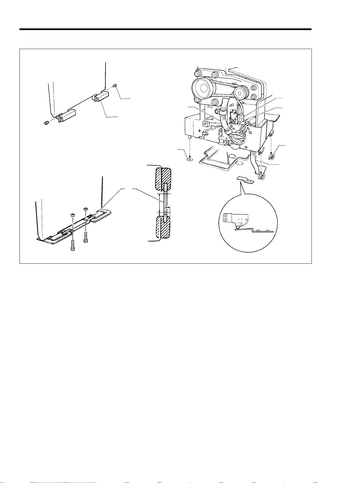
<BAS-311F-0 Solenoid type only>
(1)
(2)
(3)
(1)
S1. Make hole in the beam as shown in the illustration above. (Button hole diameter is 4.2mm)
S2. Install the ground wire (1) (accessory) to the beam with a tapping screw (2) (accessory).
S3. Loosen the screw (3), and then conne ct the ground wi re (1) that i s coming from the beam as shown in the illustration.
12
BAS-311F-0, 311F-L, 326F-0
1424S
Lock the cord
clamp at the top.
3. INSTALLATION
(10)
(21)
(20)
(13)
(12)
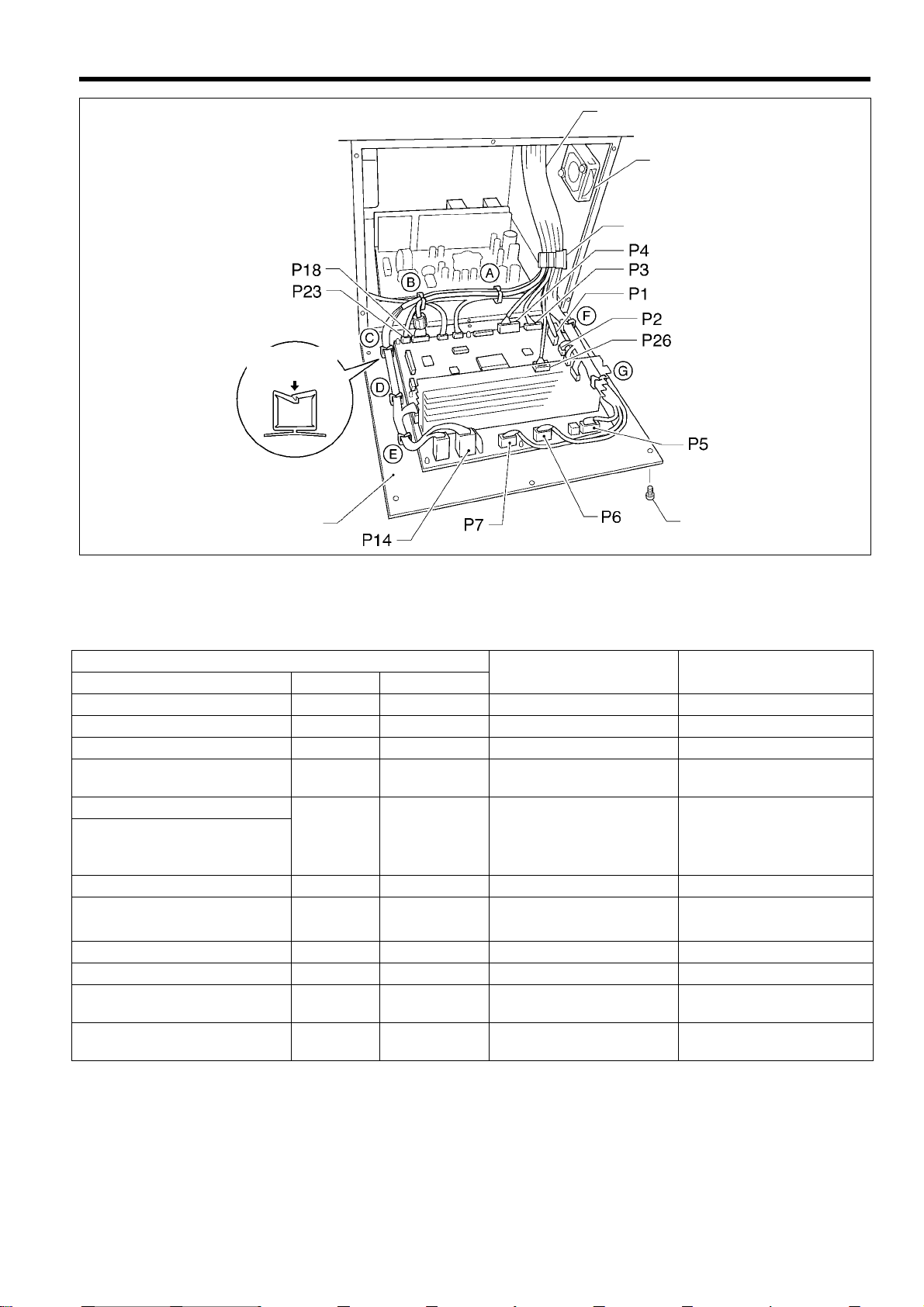
13. Securely connect connectors P1 to P7, P14, P18, P23 and P26 as indicated in table below.
Note
Check that the connector is facing the correct way, and then insert it firmly until it locks into place.
Furthermore, lock the cord clamp at the top.
Machine head connectors
Connection location
No. of pins Cord mark
Connection location on
circuit board
Cord clamps used
X, Y, Sewing sensor 12-pin [1] P1 (ORG) None
Synchronizer 5-pin [2] P2 (SYNCHRO) F
EMERGENCY STOP switch
Solenoid valve
(for pneumatic)
9-pin [3] P3 (HEAD) None
12-pin [4] P4 (VALVE) None
Solenoid
Presser foot
Thread trimmer
8-pin [5] P5 (SOL)
F, G
Wiper
Pulse motor, Y 5-pin [6] P6 (YPM) F,G
Pulse motor, X
5-pin
(blue)
[7] P7 (XPM) F, G
Upper shaft motor 3-pin None P14 (UVM) A, B, C, D, E
Operation panel 10-pin [M] P18 (PANEL) A, B
1176S
Head position switch 3-pin [23] P23 (IMSW) A, B
Machine specification select
connector
10-pin [26] P26 (SELECT) None
14. Secure the cord bundle (10) with the cord clamp (20).
Note
Check that the cords do not get pulled when the machine head is tilted back gently.
15. Close the cord presser plate (15) in the direction of the black arrow , and secure it by tightening the screws (14).
16. Install the control box cover (main P.C. board mounting plate (13)) with the six screws (12).
Note
Check that the cords do not come into contact with the fan (21) and that they are not clamped by the cover at this
time.
BAS-311F-0, 311F-L, 326F-0
13
3. INSTALLATION
3-12. Installing the belt co ver
(2)
(1)
(3)
(4)
1177S
1. Loosen the two screws (2) of the upper cover (1).
2. Insert the belt cover (3) in the direction of the arrow,
and then secure it with the two screws (2) and the two
screws (4).
* it is not necessary to remove the belt cover (3)
when tilting back the machine head.
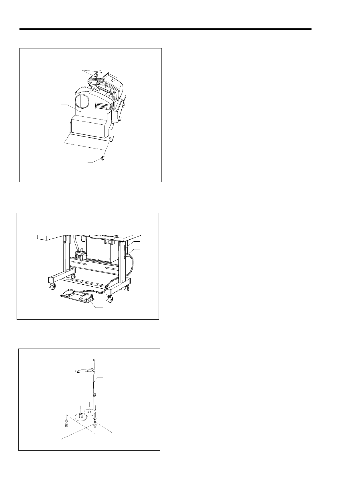
3-13. Installing the f oot s witc h
(1)
(3)
(2)
1178S
3-14. Installing the spool stand
Insert the connector of the foot switch (2) into the
connector (3) of the control box (1).
Install the spool stand (1) to the table.
14
(1)
0073Q
BAS-311F-0, 311F-L, 326F-0
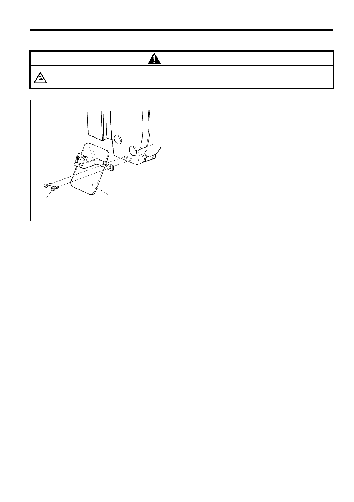
3-15. Installing the ey e guard
CAUTION
Attach all safety devices before using the sewing machine.
If the machine is used without these devices attached, injury may result.
(1)
(2)
3. INSTALLATION
Install the eye guard ass y (1) to the face plate with the
two screws (2).
1180S
BAS-311F-0, 311F-L, 326F-0
15
3. INSTALLATION
3-16. Installing the programmer (option)
[Vertical]
(2)
(1)
1181S
1. Install the programmer support (2) to the work table with the two screws (1).
2. Insert the programmer connector (4) securely into the left side of the operation panel (3).
[Flat]
(1)
(2)
(4)
(3)
1182S 1183S
3-17. Installing the w ork clamp lifter connecting rod
(BAS-311F-0 solenoid type only)
(3)
(1)
(5)
(7)
(5)
(3)
(4)
(6)
(2)
1184S
1. Remove the four screws (1), and then remove the side cover (2).
2. Install the work clamp lifter connecting rod (4) to the screw (3) on the work clamp lifter lever (5).
3. After installing, re-install the side cover (2) with the four screws (1).
Note
Remove chain hooking back (7) which is attached to the work clamp lifter pedal (6) before tilting back the machine
head.
Move the treadle support base (8) back and for th to adjust so that the ch ain which is attached to the pres s er lifter
connecting rod (4) and the presser lifter treadle (6) does not touch the cables.
(8)
1185S
16
BAS-311F-0, 311F-L, 326F-0
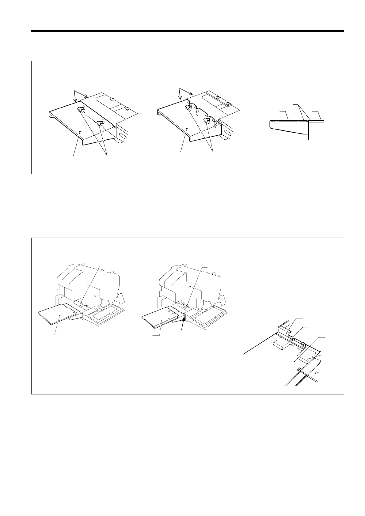
3-18. Installing the feed base cover supports
A
(BAS-311F-L, 326F-0)
BAS-311F-L
Coinside
Coinside
BAS-311F-L
Coinside
Coinside
BAS-326F-0
BAS-326F-0
3. INSTALLATION
Coinside
(2)
(3)
(2)
(2)
1168S
1168S
Loosen the four screws (1) on the side of the bed by about 2-3 turns, and then install the feed base cover supports (2) to
the side of the bed so that the top surfaces of the feed base cover supports (2) (one each at left and right) are at the same
height as the top surfaces of the X and Y feed base covers (3) (at left and right).
(1)
(1)
(2)
1169S 1186S
(1)
3-19. Installing the X f eed base cover
(BAS-311F-L, 326F-0)
1167S1 166S
(2)
(3)
(2)
BAS-311F-L
(1)
BAS-326F-0
(2)
(1)
(3)
(4)
1187S
BAS-311F-L
Loosen the four screws (1) by about 2-3 turns, slide the X feed base cover (2) (one each at left and right) in the direction
of the arrow in the illustration, and then tighten the screws (1).
BAS-326F-0
1. Loosen the four screws (2) which are holding the bellows (1) by about 2-3 turns, and then slide the X feed base cover
assemblies (3) (one each at left and right) in th e direction of the arrow in the illustration into the gaps ( section A)
between the needle plate support plate and the X and Y feed base cover (at left and right).
2. Lift the bellows (1) u p slightl y, clamp the tops and bottoms of the X feed base cover assem blies (3) (one eac h at left
and right) between the bellows (1) and the X feed base (4) and the then tighten the screws (2).
BAS-311F-0, 311F-L, 326F-0
17
3. INSTALLATION
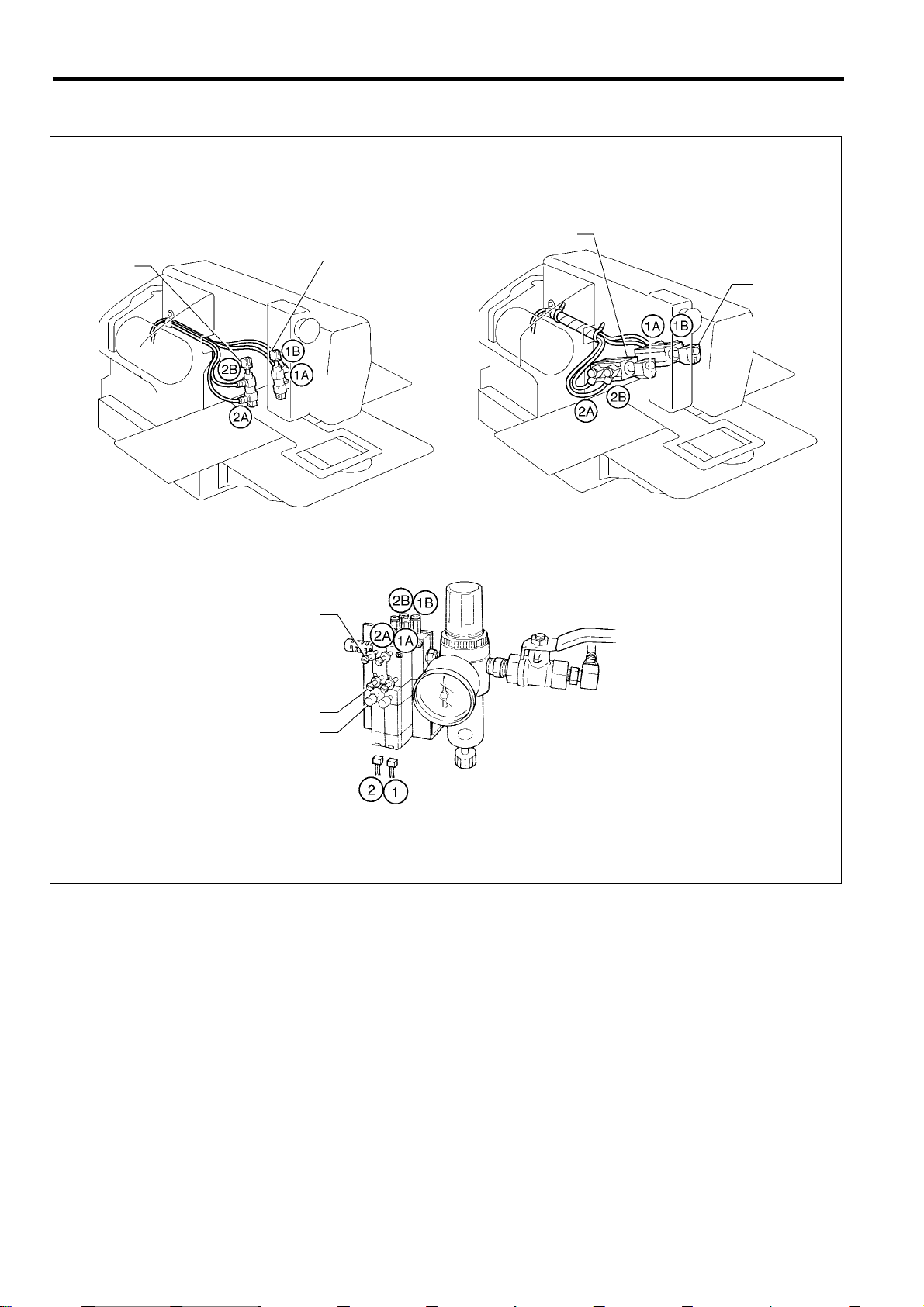
3-20. C onnecting the tubes (pneumat ic type only)
1188S
Cylinder L
BAS-311F-0, 311F-L
BAS-326F-0
1189S
Cylinder L
Cylinder R
Cylinder R
Upper knob
Lower knob
Manual button
0319Q
Connect each air tube to the position with the corresponding number.
18
BAS-311F-0, 311F-L, 326F-0
 Loading...