

Page 1

SERVICE MANUAL
MODEL: LX-200/LX-900/LX-910D
REVISED EDITION May, 2000
Page 2

Unauthorized copying of all or part of the contents of this manual is prohibited.
The contents of this manual may change without notice.
Page 3

INTRODUCTION
This Service Manual describes the Cool Laminator LX-200/900/910D specifications, operating
principles of the mechanisms, disassembly and reassembly procedures, and maintenance and
troubleshooting procedures.
This Service Manual is intended for use by trained technicians. It is not intended for use by the
user.
The manual is divided into the following chapters.
Chapter 1. Specifications
Chapter 2. Mechanism
Chapter 3. Disassembly Procedures
Chapter 4. Reassembly Procedures
Chapter 5. Electronic Controllers
Chapter 6. Maintenance
Chapter 7. Troubleshooting
Appendix Main PCB Circuit Diagram
Page 4

Chapter 1.
SPECIFICATIONS
Page 5

CONTENTS
Chapter 1. SPECIFICATIONS
1.1 Mechanical Specifications.................................................................................................1-1
1.1.1 Appearance...........................................................................................................1-1
1.1.2 Operating Panel ....................................................................................................1-1
1.1.3 Indicators...............................................................................................................1-2
1.2 Electrical Specifications ....................................................................................................1-2
1.2.1 Power Supply........................................................................................................ 1-2
1-i
Page 6
1
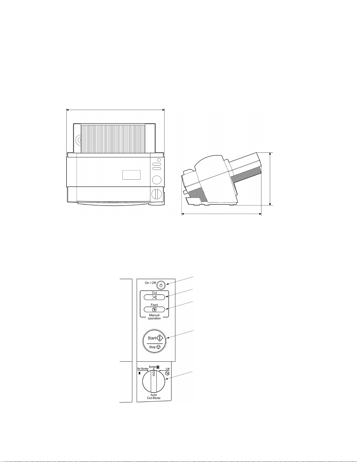
1.1 Mechanical Specifications
1.1.1 Appearance
[1] External dimensions (W x D x H) 357 mm x 293 mm x 195 mm
[2] Mass Approx. 4.6 kg (main unit only)
357 mm
195 mm
1.1.2 Operating Panel
[1] Number of Keys 5 ( Power switch, Cut key, Feed key,
Start/Stop button, Cutting mode selector)
[2] Key Arrangement
Fig. 1.1-1 Appearance
Power switch
Cut key (Horizontal)
Feed key
Start/Stop button
Cutting mode selector
293 mm
Fig. 1.1-2 Key Arrangement
1-
Page 7

2
1.1.3 Indicators
[1] Positions Start/Stop button LED indicators (red, green, orange)
1.2 Electrical Specifications
1.2.1 Power Supply
[1] Power supply Commercial power supply (locally available power supply).
Converted to DC by the AC adaptor.
1-
Page 8

Chapter 2.
MECHANISMS
Page 9

CONTENTS
Chapter 2. MECHANISMS
2.1 Mechanical Operating Principles......................................................................................2-1
2.1.1 Description of Mechanisms (Border Mode)..........................................................2-1
2.1.2 Feed and Compression Mechanisms...................................................................2-2
2.1.3 Cutter Mechanism (Border Mode)........................................................................2-4
2.1.4 Paper Size Detector Mechanism..........................................................................2-6
2.1.5 Trimming Mechanism...........................................................................................2-8
i
Page 10
1
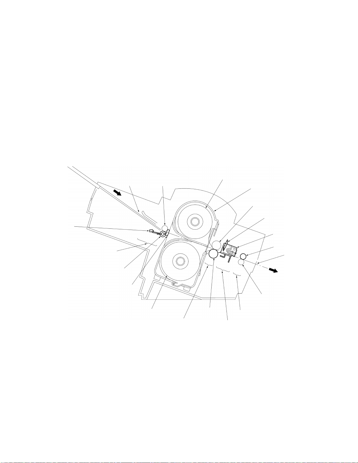
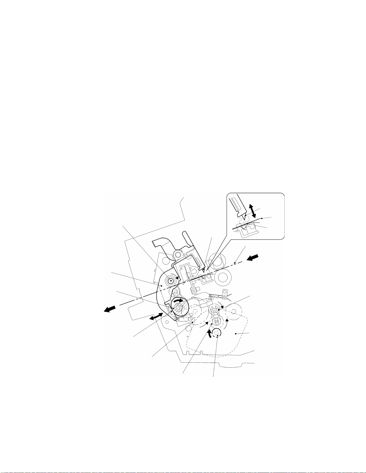
2.1 Mechanical Operating Principles
2.1.1 Description of Mechanisms (Border Mode)
1. When a document is inserted into the paper loading gate, the paper feed rollers feed
it to the driving roller.
2. As the document passes between the paper feed rollers, the paper size detector
determines its size (length and width).
3. When the document passes between the film cartridges it is sandwiched between
the upper and lower films in the compression-feed area, where the films and
document are compressed between the driving roller and sub-roller.
4. The compressed document and film is fed to the cutting area, where it is cut to the
document size detected by the paper size detector with borders added. It is then
transported to the next stage.
5. The laminated document is fed out of the eject gate by the paper eject rollers.
Paper length
detector
Paper loading gate Paper feed sub-roller
Paper loading area
Paper feed roller
Paper width detector
Roll film (upper)
Roll film (lower)
Compression-feed area
Driving roller
Fig. 2.1-1 Description of Mechanisms
Film cartridge
Sub-roller
Y-cutter blade
X-cutter unit
Paper eject roller
Eject gate
Paper eject sub-roller
Ejecting area
Cutting area
2-
Page 11
2
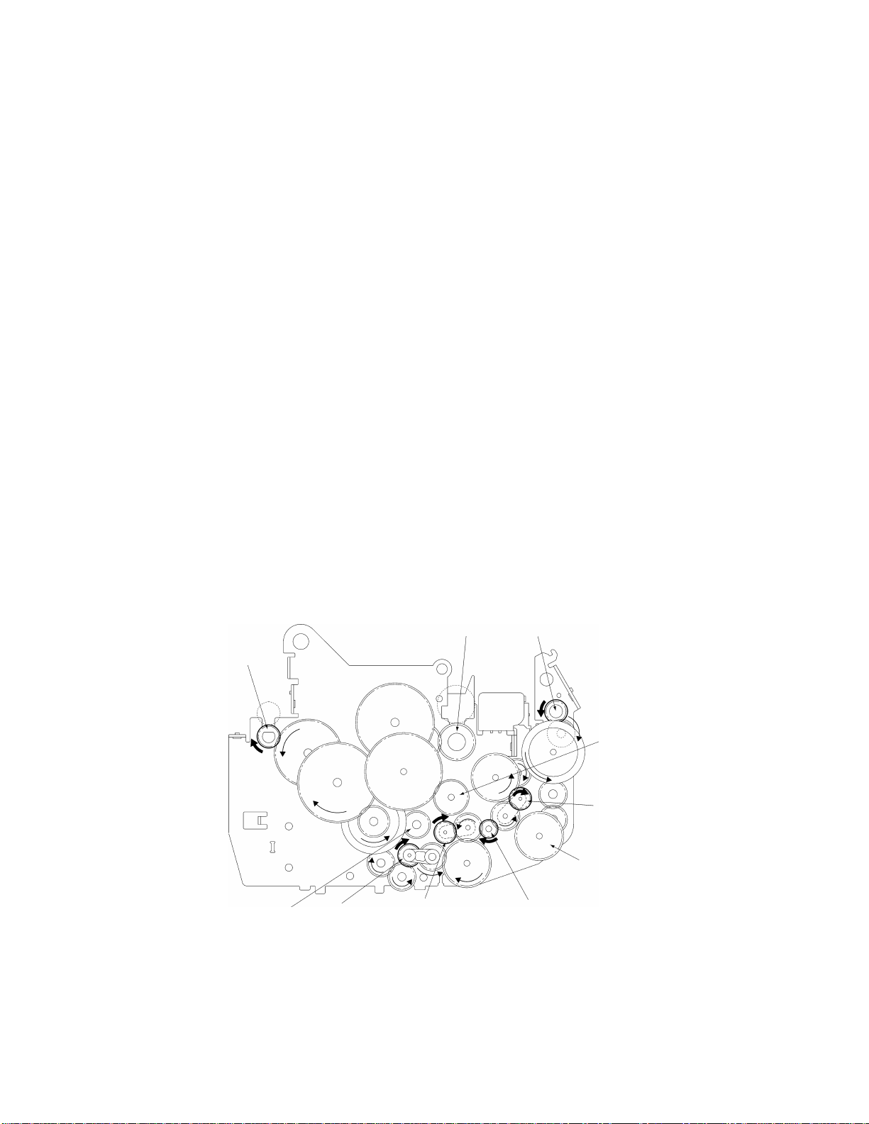
2.1.2 Feed and Compression Mechanisms
The feed and compression mechanism controls the motor drive to feed the document
into the film cartridge, compression-feed the films, and eject the laminated document.
When no compression-feed is applied while feeding a document into the film cartridge
or ejecting a laminated document, the LF motor rotates clockwise and the motor drive is
transmitted via gears to the paper feed roller and paper eject roller.
At this time, the planet gear (A) is free from the drive gear (A), such that the drive is not
transmitted to the driving roller.
During compression-feeding of the films, LF motor rotates counterclockwise to move the
planet gear (A) against the drive gear (A), such that the drive from the LF motor is
transmitted to the driving roller.
Also, planet gear (B) moves against the drive gear (B) and planet gear (C) moves
against the drive gear (C), such that the LF motor drive continues to be transmitted to
the paper feed roller and paper eject roller, without changing the direction of roller
rotation.
• Operation when Feeding Document into the Film Cartridge or when Ejecting a
Laminated Document
1. When the LF motor rotates clockwise (as indicated by the arrow in the diagram),
the drive is transmitted via a series of gears to drive the paper feed roller and
paper eject roller in the directions indicated by the arrows. At this time, planet
gear (A) is free, such that no drive is transmitted to drive gear (A) and the driving
roller does not rotate.
2. The document is fed into the film cartridge when the paper feed roller rotates in
the direction indicated by the arrow.
3. The laminated document is ejected from the eject gate when the paper eject
roller rotates in the direction indicated by the arrow.
Driving roller Paper eject roller
Paper feed roller
Drive gear (A)
Planet gear (C)
Drive gear (C)
Drive gear (B)
Planet gear (B)
LF motor gearPlanet gear (A)
Fig. 2.1-2 Operation when Feeding Document into the Film Cartridge or when Ejecting a Laminated Document
2-
Page 12
3
•
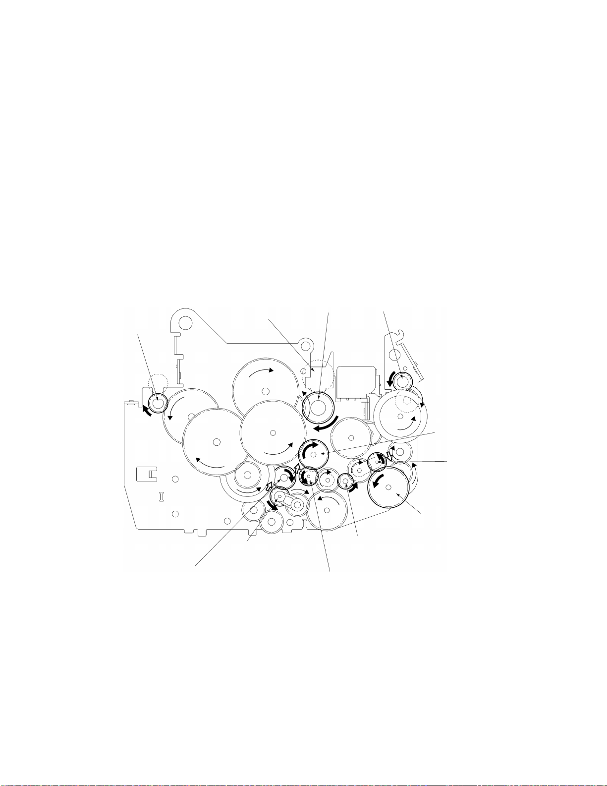
Operation During Film Compression-Feed
1. When the leading edge of the document enters the compression-feed area, LF
motor starts to rotate counterclockwise, as indicated by the arrow.
2. Planet gear (A), which had been free, moves to engage with drive gear (A). The
drive from the LF motor is then transmitted to the various gears, as shown in the
diagram, and the driving roller rotates as indicated by the arrow. Also, planet
gear (B) moves against the drive gear (B) and planet gear (C) moves against the
drive gear (C), such that the LF motor drive continues to be transmitted to the
paper feed roller and paper eject roller, without changing the direction of roller
rotation.
3. The rotation of the driving roller is transmitted to the sub-roller. These rollers
feed the films and press them against the document. At this time, the rotations
of the paper feed roller and paper eject roller continue uninterrupted.
4. When the trailing edge of the document leaves the compression-feed area and
the X-cutters finish cutting the film, the LF motor reverses to rotate
counterclockwise. Planet gear (A) again becomes free such that the driving
roller rotation stops and feeding of the films also stops.
Paper feed roller
Drive gear (B)
Sub-roller
Planet gear (B)
Fig. 2.1-3 Operation During Film Compression-Feed
Driving roller Paper eject roller
LF motor gear
Planet gear (A)
Drive gear (A)
Planet gear (C)
Drive gear (C)
2-
Page 13
4
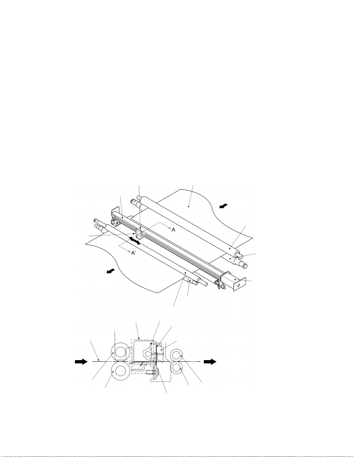
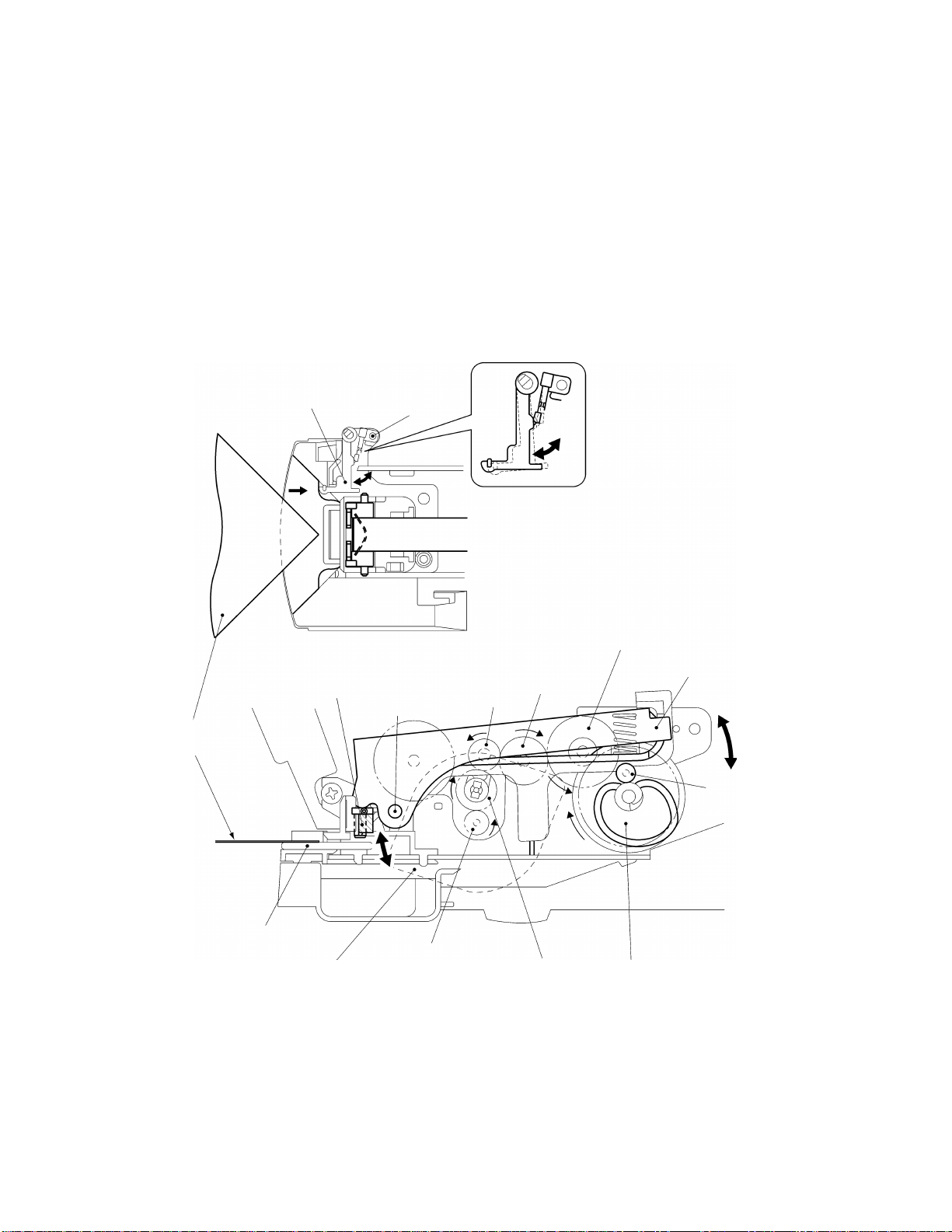
2.1.3 Cutter Mechanism (Border Mode)
The cutter mechanism cuts the laminated document to the size of the document plus an
added border. Both edges of the films are cut to suit the width of the document and the
leading edge and trailing edge are cut according to the document length.
•
Y-Cutter Vertical Drive Operation
1. The TC motor rotates clockwise from its reference position to drive the cam
clockwise via a series of gears. The cam rotates the Y-diversion lever clockwise
about its pivot. (All rotations indicated by arrows. )
When the Y-diversion lever reaches its maximum displacement position with the
cam at approximately its 180°‹ rotated position, rotation of the TC motor pauses.
2. When the Y-diversion lever reaches its maximum displacement position, its
movement lowers the two Y-cutter blades from the standby position to the
cutting position, where they start cutting the edges of the laminated film.
3. When the Y-axis cutters reach the trailing edge cutting position, the TC motor
starts rotating again and stops when it reaches its reference position. This
rotation returns the cam and Y-diversion lever to their original positions and the
cutters move to their standby positions.
Pivot
Y-diversion lever
Cam (hatched area)
Idle gear 3
Y-cutter blade
Idle gear 2
Idle gear 1
Fig. 2.1-4 Y-Cutter Vertical Drive Operation
TC motor gear
Standby position
Film surface
Planet gear
TC motor
Film
Cutting
position
2-
Page 14
5
•
Cutting Leading and Trailing Edges (X-cutter Mechanism)
1. All the rollers which feed the document stop when the cut position at the leading
edge of the document reaches the cutting position of the rotary cutter and fixedblade cutter.
2. The DC motor rotates to drive the carriage in the X-cutter assembly via the spiral
mechanism (not illustrated).
3. As the carriage makes a reciprocal movement, the rotary cutter attached to the
carriage moves against the fixed cutter to cut the compressed leading edge of
the document.
4. The rotation of the rollers which feed the document restarts when the cutting of
the leading edge is complete. Then, when the cut position at the trailing edge of
the document reaches the cutting position of the rotary cutter and fixed-blade
cutter, the feed rollers stop again.
5. The document trailing edge is cut in the same way as the leading edge, by a
reciprocal movement of the rotary cutter attached to the carriage.
6. The rotation of the rollers restarts to feed the laminated document from the eject
gate after the cutting of the trailing edge is complete.
Rotary cutter Document
X-cutter
Document
Section A-A’
Frame
DC motor
Sub-roller
Driving roller
DC motor
Paper eject sub-roller
Paper eject roller
Frame
Rotary cutter
Carriage
Sub-roller
Driving roller
Paper eject sub-roller
Fixed cutter
Paper eject roller
Fig. 2.1-5 Cutting Leading and Trailing Edges (X-cutter Mechanism)
2-
Page 15
6
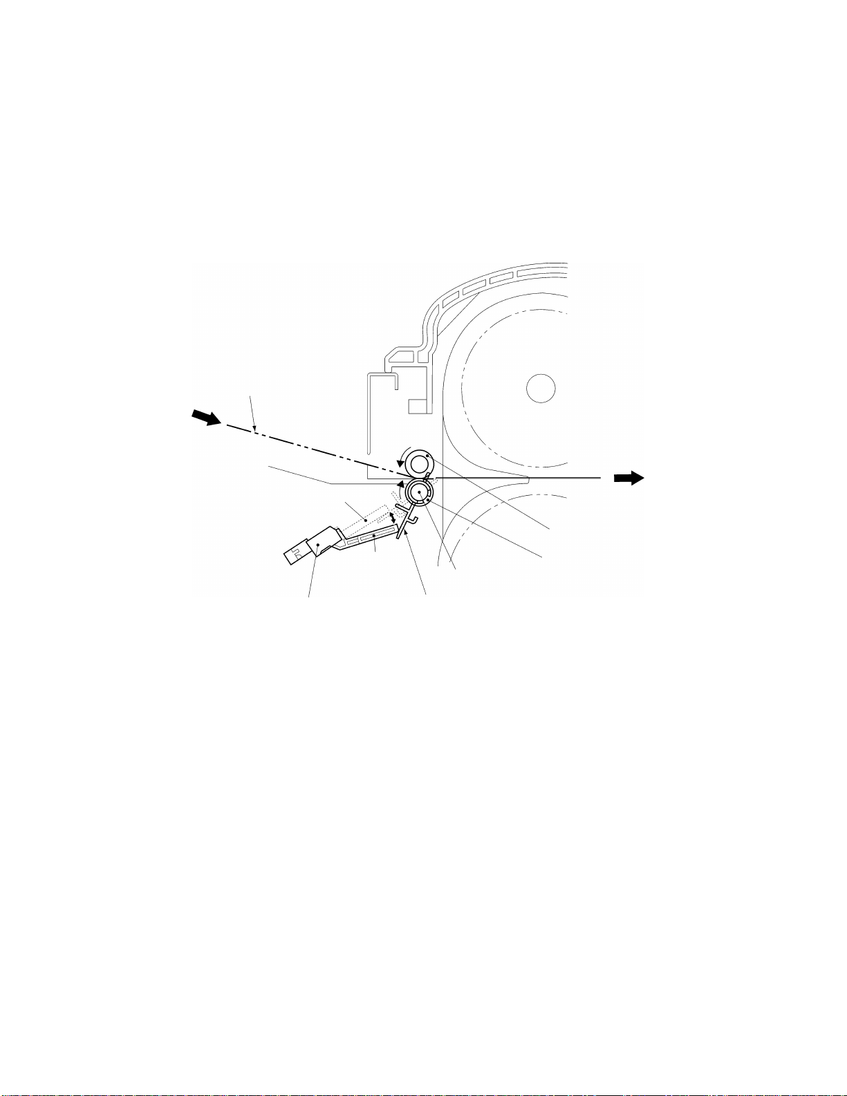
2.1.4 Paper Size Detector Mechanism
• Paper Length Detection
1. When the leading edge of the document passes between the paper feed rollers,
it rotates the paper sensor crank about the pivot to turn on the paper sensor
which detects the document leading edge.
2. When the trailing edge of the document passes out of the paper feed rollers, the
paper sensor crank reverts to its original position to turn off the paper sensor to
detect the document trailing edge.
Document feed surface
ON
Paper sensor
OFF
Pivot
Paper sensor crank
Fig. 2.1-6 Paper Length Detection
Paper feed sub-roller
Paper feed roller
2-
Page 16
7
•
Paper Width Detection
1. The Y-cutter arm L (sensor unit) moves in the direction of the arrow. When the
PL detect lever touches the document, it rotates about the pivot to switch off the
photosensor.
2. When the photosensor turns off, the Y-cutter arm L movement stops and this
position is detected as the document width.
Y-cutter arm L
Sensor unit
Document
Photosensor
PL detect lever
Part of the PL detect lever that touches the document.
* Photosensor ON status
* Photosensor OFF status
Fig. 2.1-7 Paper Width Detection
Pivot
2-
Page 17
8
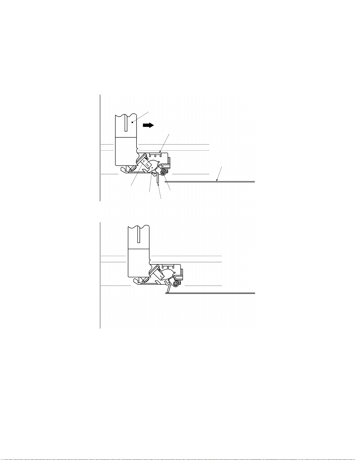
2.1.5 Trimming Mechanism
1. When a corner of the laminated document is inserted over the T-cutter plate, the
sensor lever operates a leaf switch that detects the document.
2. When the document is detected, the motor gear of TC motor rotates in the direction
of the arrow (counterclockwise) from its reference position to drive the T-cam gear in
the direction indicated by the arrow (clockwise) via a series of gears.
3. Rotation of the T-cam gear forces the T-cam roller to make a vertical movement,
such that T-lever1 moves vertically, rotating around its pivot.
4. As T-lever 1 moves vertically, the T-cutter mounted on the end of T-lever 1 moves
up and down, trimming the corner of the laminated document into a rounded radius.
Laminated
document
T-sensor lever
T-cutter
Leaf switch
Pivot
Planet gear
Idle gear 3
T-lever 1
Idle gear 2
T-cam roller
T-cutter plate
Motor gear
T-cam gearIdle gear 1TC motor
Fig. 2.1-8 Trimming Mechanism
2-
Page 18

Chapter 3.
DISASSEMBLY PROCEDURES
Page 19

CONTENTS
Chapter 3. DISASSEMBLY PROCEDURES
3.1 Safety Precautions ............................................................................................................3-1
3.2 Removing the Film Cartridge............................................................................................3-1
3.3 Covers...............................................................................................................................3-2
3.3.1 Removing the Trimmer Upper Cover...................................................................3-2
3.3.2 Removing the Top Cover......................................................................................3-3
3.3.3 Removing the Sub-tray.........................................................................................3-4
3.3.4 Removing the Paper Tray and Paper Guide.........................................................3-4
3.3.5 Removing the Body Cover B.................................................................................3-5
3.3.6 Removing the Front Cover....................................................................................3-7
3.3.7 Removing the Cover Switch Assy ........................................................................3-8
3.3.8 Removing the Dial Switch Holder Assy B.............................................................3-9
3.3.9 Disassembling the Dial Switch Holder Assy B ...................................................3-10
3.4 Chassis............................................................................................................................3-12
3.4.1 Removing the Harness Connectors....................................................................3-12
3.4.2 Removing the PE Sensor Unit............................................................................3-12
3.4.3 Removing the Chassis Unit ................................................................................3-13
3.5 PCBs................................................................................................................................3-15
3.5.1 Removing the Main PCB Assy............................................................................ 3-15
3.5.2 Removing the Jack PCB Assy............................................................................3-15
3.5.3 Removing the Switch PCB Assy.........................................................................3-16
3.6 T-Chassis ........................................................................................................................3-17
3.6.1 Removing the T-Chassis Unit............................................................................. 3-17
3.6.2 Disassembling the T-Chassis Unit...................................................................... 3-18
3.7 Y-CA Chassis .................................................................................................................. 3-19
3.7.1 Removing the Y-CA Chassis Assy .....................................................................3-19
3.7.2 Disassembling the Y-CA Chassis Assy..............................................................3-20
3.7.3 Removing the Roller Holder Assy.......................................................................3-21
3.7.4 Disassembling the Roller Holder Assy ...............................................................3-22
3.8 Sensor Frame and Y-cutter Arm L..................................................................................3-23
3.8.1 Removing the Sensor Frame..............................................................................3-23
3.8.2 Removing the Y-cutter Arm L .............................................................................3-23
3.8.3 Disassembling the Sensor Frame ......................................................................3-24
3.8.4 Disassembling the Y-cutter Arm L...................................................................... 3-25
3.9 Paper Feed Roller ........................................................................................................... 3-26
3.9.1 Removing the Paper Feed Sub-roller Assy........................................................3-26
3.9.2 Removing the Paper Feed Roller Assy...............................................................3-27
i
Page 20

3.10 Paper Eject Roller ...........................................................................................................3-28
3.10.1 Removing the Y-D Shaft.....................................................................................3-28
3.10.2 Removing the Paper Eject Sub-roller Unit.......................................................... 3-29
3.10.3 Removing the Paper Eject Roller Unit................................................................ 3-29
3.11 Y-diversion Lever ............................................................................................................3-30
3.11.1 Removing the Y-diversion Lever Assy................................................................ 3-30
3.11.2 Disassembling the Y-diversion Lever Assy ........................................................ 3-31
3.12 X-cutter............................................................................................................................3-32
3.12.1 Removing the X-cutter Unit.................................................................................3-32
3.12.2 Disassembling the Tape Sensor Unit .................................................................3-32
3.13 Driving Roller................................................................................................................... 3-33
3.13.1 Removing the Driving Roller...............................................................................3-33
3.14 Left Side of the Chassis ..................................................................................................3-33
3.14.1 Removing the Gears...........................................................................................3-33
3.14.2 Disassembling the Left Side of the Chassis.......................................................3-35
3.15 Right Side of the Chassis................................................................................................3-36
3.15.1 Disassembling the Right Side of the Chassis..................................................... 3-36
3.16 Lower Chassis.................................................................................................................3-37
3.16.1 Removing the Left and Right Sides of the Chassis............................................3-37
3.16.2 Removing the Cassette Holder...........................................................................3-38
3.16.3 Removing the Encoder (ENC) Sensor PCB.......................................................3-38
3.16.4 Removing the Cassette Detect Switch...............................................................3-39
ii
Page 21
3.1 Safety Precautions
When conducting disassembly operations, place the unit on a grounded anti-static
sheet. LSI and other electronic components are sensitive to static electricity
and may be damaged if touched while charged.
Before transporting a circuit board, wrap it in a conducting sheet such as aluminum
foil.
When using a soldering iron or other heat-producing tool, ensure that heat does not
damage wires, circuit boards, or plastic parts such as covers.
Take care not to lose small screws or washers removed when replacing parts.
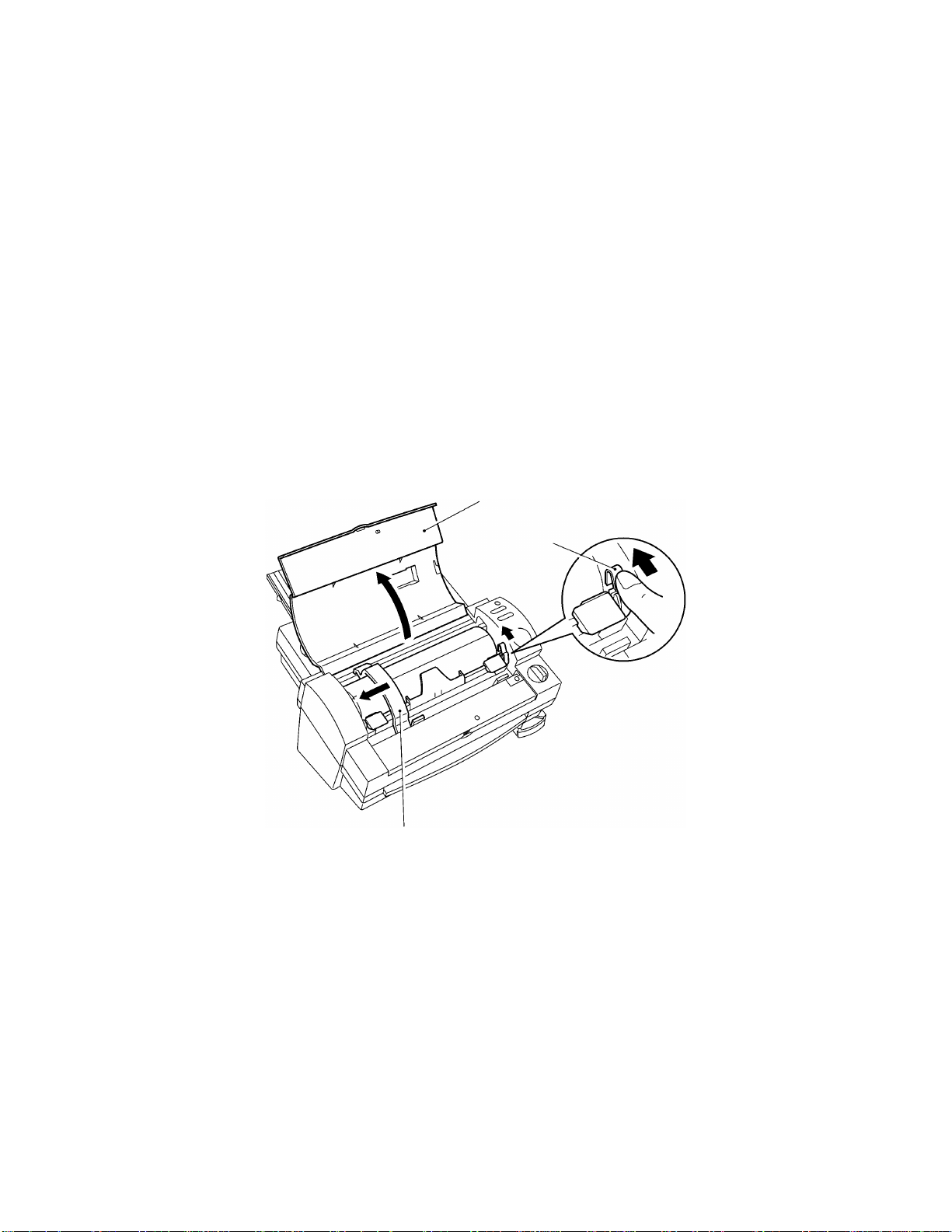
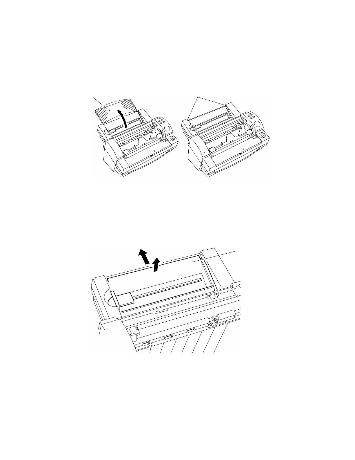
3.2 Removing the Film Cartridge
1.Open the top cover and move the Y-cutter arm L as far as possible to the left.
2.Push the lock lever R in the direction indicated by the arrow to unlock the roller
holder assy.
Top cover
Lock lever R
Y-cutter arm L
Fig. 3.2-1 Removing the Film Cartridge 1
3-1
Page 22
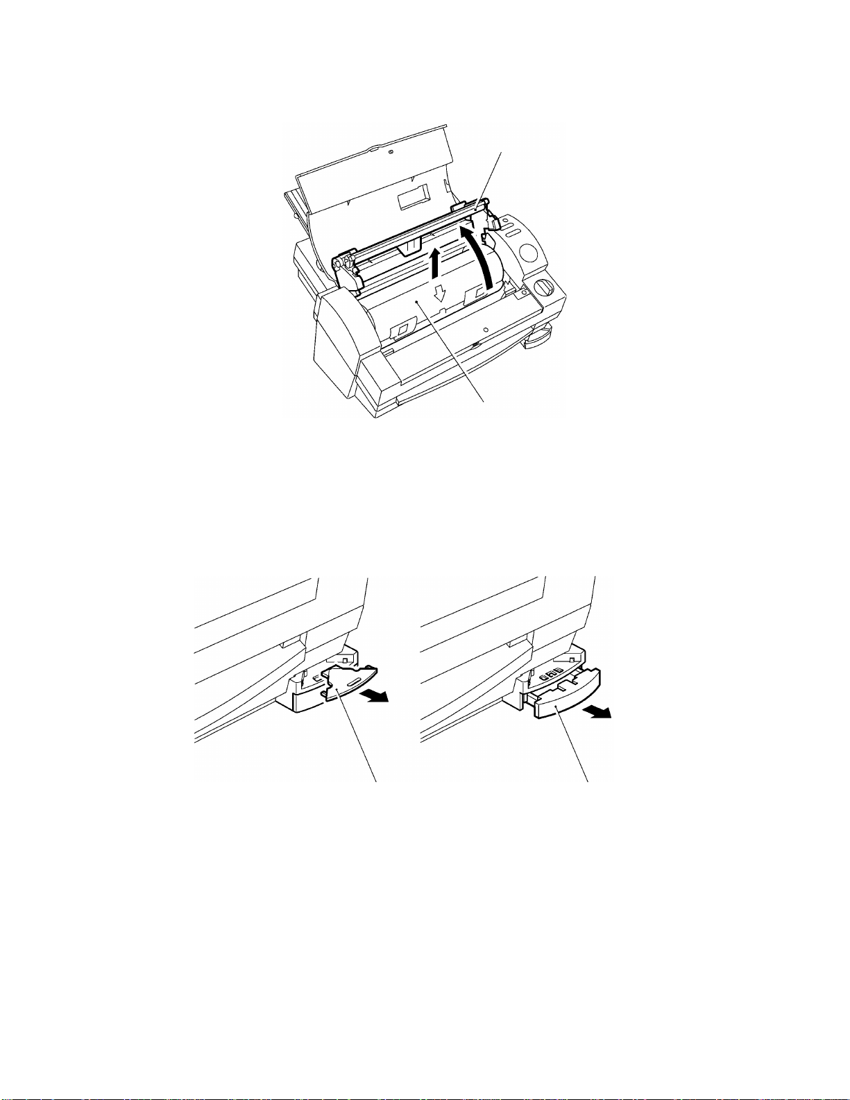
3.Lift up the roller holder assy and pull out the film cartridge.
3.3 Covers
Roller holder assy
Film cartridge
Fig. 3.2-2 Removing the Film Cartridge 2
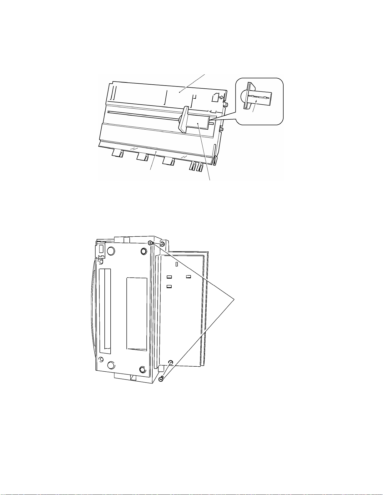
3.3.1 Removing the Trimmer Upper Cover
1.Pull out the T-cutter plate and the trimmer bottom cover.
T-cutter plate Trimmer bottom cover
Fig. 3.3-1 Removing the Trimmer Cover 1
3-2
Page 23
2.Set the unit on its side with the trimmer cover uppermost.
Remove the two trimmer cover screws. Remove the trimmer upper cover.
Trimmer upper
cover
Fig. 3.3-2 Removing the Trimmer Upper Cover 2
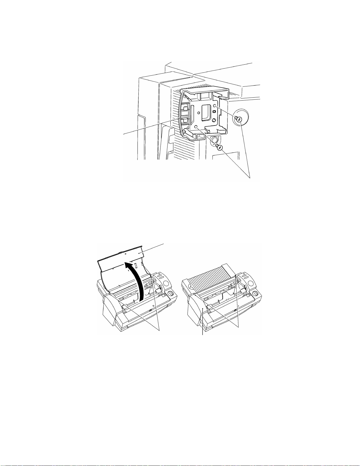
3.3.2 Removing the Top Cover
Trimmer cover screws
Open the top cover. Lift the top cover shafts out of the shaft recesses in the body
cover and remove the cover.
Top cover
Shaft recesses
Body cover
Shafts
Fig. 3.3-3 Removing the Top Cover
3-3
Page 24
3.3.3 Removing the Sub-tray
1.Open the sub-tray.
2.Flex the center of the sub-tray toward you to release the shafts from the shaft
recesses in the body cover. Remove the sub-tray.
Sub-tray
Fig. 3.3-4 Removing the Sub-tray
Shaft recesses
Body cover
3.3.4 Removing the Paper Tray and Paper Guide
1.Lift the top of the paper tray in the direction of arrow A, then pull it in the direction
of arrow B. Remove the paper tray.
“B”
“A”
Paper tray
Fig. 3.3-5 Removing the Paper Tray
3-4
Page 25
2.Disengage the paper guide hook (at the rear of the paper tray) from the paper
tray. Remove the paper guide.
Paper tray film
Fig. 3.3-6 Removing the Paper Guide
3.3.5 Removing the Body Cover B
1.Remove the two bottom cover screws A from the bottom of the bottom cover.
Paper tray
Hook
Paper guide
Bottom cover screws A
Fig. 3.3-7 Removing the Body Cover B (1)
3-5
Page 26
2.Lift the rear of the bottom cover in the direction of arrow B while pushing it in the
direction of arrow A. Release the four hooks at the rear face.
3.Push the body cover in the directions indicated by the arrows C to release the
hook at the left and right side.
4.Release the two hooks from the front of the body cover.
Hook
“B”
“A”
“C”
Body cover
“C”
Rear hooks
Side hook
Front hooks
Bottom cover
Fig. 3.3-8 Removing the Body Cover (2)
5.Disconnect the switch harness assy (white CN1) from the main PCB and remove
the body cover. (The body cover switch PCB is connected to the main PCB of
bottom cover via the switch harness assy.)
Fig. 3.3-9 Removing the Body Cover (3)
Switch harness assy
3-6
Page 27
3.3.6 Removing the Front Cover
1.Remove the two front cover screws under the bottom cover.
Front cover screws
Fig. 3.3-10 Removing the Front Cover (1)
2.While pressing up the two hooks on the front cover from underneath, pull the front
cover out to remove it.
Hook
Front cover
Fig. 3.3-11 Removing the Front Cover (2)
3-7
Page 28
3.3.7 Removing the Cover Switch Assy
1.Disconnect the cover switch assy harness connector (yellow CN4) located under
the body cover from the switch PCB.
2.Remove the cover switch screw. Remove the cover switch assy.
Cover switch assy
Cover switch screw
Harness connector
Front
Fig. 3.3-12 Removing the Cover Switch Assy
3-8
Page 29
3.3.8 Removing the Dial Switch Holder Assy B
1.Disconnect the leaf switch R assy (red CN2) and leaf switch L assy (white CN3)
harness connectors from the switch PCB.
2.Remove the dial lock arm and the dial lock arm spring that is hooked on the body
cover.
3.Remove the switch harness assy from switch PCB.
4.Remove the two dial holder screws. Remove the Dial Switch Holder Assy B.
Leaf switch R assy
Dial holder screws
Dial switch holder
assy B
Leaf switch L assy
Dial lock arm spring
Dial lock arm
Fig. 3.3-13 Removing the Dial Switch Holder Assy B
3-9
Page 30

3.3.9 Disassembling the Dial Switch Holder Assy B
1.Pull the plate spring in the direction of the arrow. Remove dial switch B.
2.Remove the two leaf switch R/L screws. Remove the leaf switch R assy (red
CN2) and the leaf switch L assy (white CN3).
Dial switch B
Leaf switch R/L assy’s
Plate spring
Leaf switch R/L screws
Fig. 3.3-14 Disassembling the Dial Switch Holder Assy B (1)
3.Remove the slide plate spring screw. Remove the plate spring.
4.Lift the slide plate 1B diagonally upward. Disengage slide plate 1B from the hook
and remove it.
Slide plate spring screw
Slide plate 1B
Plate spring
Fig. 3.3-15 Disassembling the Dial Switch Holder Assy B (2)
3-10
Page 31

5.Remove the slide plate screw. Remove slide plate 2 from slide plate 1B.
Dial Switch holder
Slide plate screw
Slide plate 2
Slide plate 1B
Fig. 3.3-16 Disassembling the Dial Switch Holder Assy B (3)
6.Disconnect lug A on the dial lock arm from the dial switch holder. Pull the dial
lock arm off the shaft.
D ial lock arm
Lug “A”
Fig. 3.3-17 Disassembling the Dial Switch Holder Assy B (4)
3-11
Page 32

3.4 Chassis
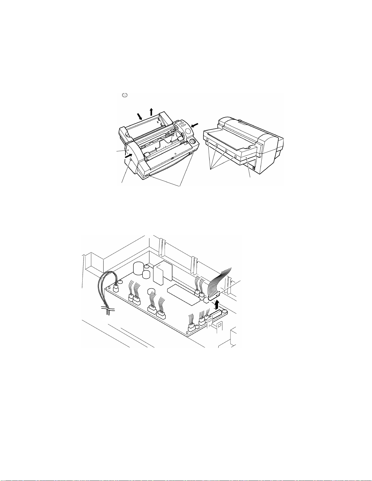
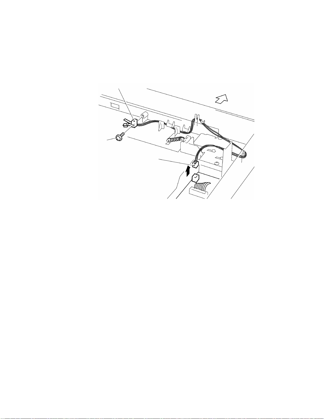
3.4.1 Removing the Harness Connectors
Remove 12 harness connectors from the main PCB. Do not remove the power
harness assy (red/black CN13).
Power harness assy
Fig. 3.4-1 Removing the Harness Connectors
3.4.2 Removing the PE Sensor Unit
Open the bearing supports in the bottom cover outward. Lift the PE sensor unit out
of the bottom cover bearing supports. Pull the tip of the PE sensor unit off the
paper feed roller shaft and remove the PE sensor unit. Take care not to damage
the tip of the PE sensor unit when disconnecting it.
PE sensor unit
Bearing supports
Fig. 3.4-2 Removing the PE Sensor Unit
Paper feed roller Assy
3-12
Page 33

3.4.3 Removing the Chassis Unit
1.Remove the sensor frame screw from the sensor frame. Remove the ground wire
(jack PCB). After removing the wire, reinsert the sensor frame screw to fasten
the sensor frame to the chassis.
Ground wire (jack PCB)
Sensor frame
Sensor frame screw
Fig. 3.4-3 Removing the Chassis Unit (1)
2.Remove the two bottom cover screws B and the spring washers from under the
bottom cover B.
Bottom cover
Bottom cover screws
Fig. 3.4-4 Removing the Chassis Unit (2)
3-13
Page 34

3.Remove the cassette holder screws from under the chassis unit.
Cassette holder screws
Fig. 3.4-5 Removing the Chassis Unit (3)
4.Pull out the chassis unit.
Chassis unit
Fig. 3.4-6 Removing the Chassis Unit (4)
3-14
Page 35

3.5 PCBs
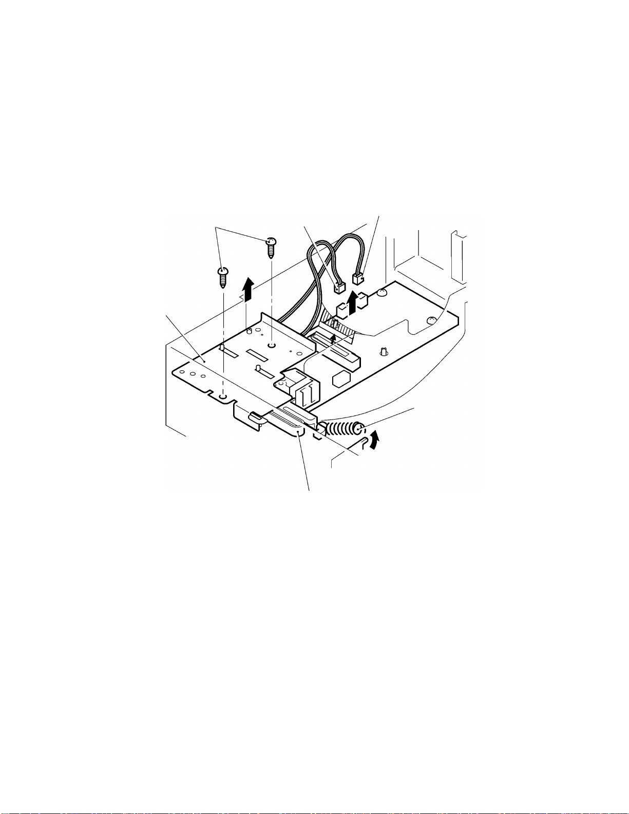
3.5.1 Removing the Main PCB Assy
1.Disconnect the power harness assy (red/black CN13) from the Main PCB assy 1.
2.Remove the four main PCB screws. Remove the Main PCB assy 1.
Main PCB screws
P ower harness assy
Main PCB assy 1 Main PCB screws
Fig. 3.5-1 Removing the Main PCB Assy
3.5.2 Removing the Jack PCB Assy
Remove the Jack PCB screw and remove the jack PCB assy 1.
Jack PCB screw
Fig. 3.5-2 Removing the Jack PCB Assy
Ferrite core
Jack PCB assy 1
3-15
Page 36

3.5.3 Removing the Switch PCB Assy
1.Remove the two switch PCB screws A and three switch PCB screws B from
under the body cover B. Remove the switch PCB assy 1.
Switch PCB screws B
SW PCB
Switch PCB screws A
assy 1
Fig. 3.5-3 Removing the Switch PCB Assy (1)
2.Remove the start switch B,start key film, start key actuator, two-connection
switch, and power switch.
wo-connection switch
T
tart key actuator
S
Fig. 3.5-4 Removing the Switch PCB Assy (2)
3-16
Page 37

3.6 T-Chassis
3.6.1 Removing the T-Chassis Unit
1.Remove the plate spring screw. Remove the plate spring.
2.Remove the two T-chassis screws and remove the T-chassis unit.
T-chassis unit
Plate spring screw
Plate spring
T-chassis screw
Fig. 3.6-1 Removing the T-Chassis Unit
3-17
Page 38

3.6.2 Disassembling the T-Chassis Unit
1.Open hook A on the T-paper guide in the direction A'. Pull out the T-lever shaft to
remove the T-lever unit.
2.Remove T-lever 2 from T-lever 1. Remove the T-push spring and T-cam roller.
3.Remove the leaf switch TRI screw and remove the leaf switch TRI assy.
4.Disconnect the switch lever from the shaft hook on the T-paper guide and remove
the switch lever.
5.Remove the T-cutter upper unit from the T-paper guide. Remove the T-cutter
stopper from the T-cutter holder, then remove the T-cutter.
6.Remove the paper guide screw and remove the T-paper guide.
7.Remove the leaf switch TRG screw and remove the leaf switch TRG assy.
8.Turn the T-sensor lever until lug A aligns with the slot in the T-chassis and
remove the T-sensor lever.
9.Disengage hook B on the T-cam gear. Pull out the T-cam shaft to release T-gear
35-14 and T-idle gear.
T-cutter stopper
Leaf switch TRI screw
Paper
guide
screw
T-cutter holder
T-cutter upper unit
Leaf switch TRG screw
T-sensor lever
Leaf switch TRG assy
Leaf switch TRI assy
Switch lever
Shaft hook
T-paper guide
T-lever 1
T-push spring
A ’
T-lever 2
Lug “A”
T-cutter
Hook A
Slot
T-gear 35-14
T-idle gear
T-lever shaft
T-chassis
T-lever unit
T cam roller
Hook B
T-cam gear
T-cam shaft
Fig. 3.6-2 Disassembling the T-Chassis Unit
3-18
Page 39

3.7 Y-CA Chassis
3.7.1 Removing the Y-CA Chassis Assy
1. Remove the Y-extension spring L.
2. Remove the two Y-CA chassis screws
3. Remove the Y-CA timing belt from the Y-cutter arm and remove the Y-CA chassis
assy.
Y-extension spring L
Y-cutter arm
Y-CA timing belt
Y-CA chassis screws
Fig. 3.7-1 Removing the Y-CA Chassis Assy
Y-CA chassis assy
3-19
Page 40

3.7.2 Disassembling the Y-CA Chassis Assy
1. Remove the pulley holder screw. Move the Y-CA pulley holder in the direction of
arrow A and remove the Y-CA timing belt.
2. Move the Y-CA pulley holder in the direction of arrow B and remove it.
3. Move the Y-CA idle pulley in the direction of arrow B and remove it.
4. Remove the Y-CA driving pulley ring and pull off the Y-CA driving pulley.
5. Remove the two Y-CA motor screws and remove the Y-CA motor.
Y-CA driving pulley ring
Y-CA driving pulley
Y-CA motor
screws
Y-CA motor
Y-CA timing belt
“A”
Anti-static brush
Fig. 3.7-2 Disassembling the Y-CA Chassis Assy
Y-CA idle pulley
Y-CA pulley
holder screw
“B”
Y-CA pulley holder
3-20
Page 41

3.7.3 Removing the Roller Holder Assy
1. Move the Y-cutter arm L as far as possible to the left.
2. Lift up the roller holder assy and remove the roller holder spring.
3. Remove the two roller holder rings. Push the roller holder assy to the right to
disengage it from the chassis unit L boss shaft. Disengage the roller holder assy
from the chassis unit R boss shaft.
Roller holder assy
Y-cutter arm L
Chassis unit L boss shaft
Roller holder rings
Fig. 3.7-3 Removing the Roller Holder Assy
Chassis unit R boss
Roller holder ring
3-21
Page 42

3.7.4 Disassembling the Roller Holder Assy
1. Disengage the two hooks A and remove the side covers L/R.
2. Remove the lock lever springs L/R from inside the lock levers L/R to allow the lock
levers L/R to move freely.
3. Turn hook B on lock lever L to the position of the cut-out on the roller holder and
remove lock lever L. Pull out the lock lever shaft and remove the set buttons L/R,
lock lever springs L/R, and the interference board.
4. Turn hook C on lock lever R to the position of the cut-out on the roller holder and
remove lock lever R.
5. Remove the extension springs 0.4 from the left and right.
6. Pull the sub-roller bearings L/R out of the boss holes and remove them from the
release plates L/R.
7. Remove the sub-roller bearings L/R, tape hold bearings L/R, and tape hold shaft
from the sub-roller assy.
8. Remove the press roller springs L/R.
9. Remove the release plate rings. Remove the release plates L/R.
Hooks A
Lock
Hook B
lever L
Side cover L
Release plate L
Press roller spring L
Boss hole
Release
plate ring
Sub-roller
bearing L
Tape hold
bearing L
Tape hold shaft
Set button L
Cut-out
Roller holder
Lock lever
spring L
Extension
spring 0.4
Sub-roller assy
Fig. 3.7-4 Disassembling the Roller Holder Assy
Lock lever
shaft
Interference
board
Tape hold bearing R
Sub-roller bearing
Extension
spring 0.4
Lock lever
spring R
Cut-out
Set button
R
Boss hole
Release plate R
Lock lever R
Hook C
Hook A
Press roller spring R
Release plate ring
Side
cover R
Hook A
3-22
Page 43

3.8 Sensor Frame and Y-cutter Arm L
3.8.1 Removing the Sensor Frame
1. Position the chassis unit as shown in the diagram. Remove the paper sensor crank
from the paper feed roller.
2. Remove the two sensor frame screws.
3. Lift the right end of the sensor frame to release it from the top-right boss. Move the
sensor frame to the left to release it from the two bosses at the left. Remove the
sensor frame.
Sensor frame screws
Paper sensor crank
Sensor frame
Fig. 3.8-1 Removing the Sensor Frame
Chassis left sideChassis right side
3.8.2 Removing the Y-cutter Arm L
Remove the two arm shaft rings and pull the Y-cutter arm shaft in the direction of the
arrow to remove the Y-cutter arm L.
Y-cutter arm L
Y-CA chassis screw
Fig. 3.8-2 Removing the Y-cutter Arm L
Y-cutter arm L
Y-CA timing belt
3-23
Page 44

3.8.3 Disassembling the Sensor Frame
1. Disengage the hooks on FPC holder A from the cut-outs in the sensor frame. Move
the FPC holder A in the direction of the arrow to remove it.
2. Release the FPC holder B from the boss hole in the sensor frame. Move the FPC
holder B in the direction of the arrow to remove it.
3. Remove the paper sensor harness assy (flat cable) from the FPC holder A and FPC
holder B.
4. Remove the sensor crank protect film from the sensor frame, if it requires replacing.
Sensor frame
Cut-out
FPC holder A
Hook
Boss hole
Sensor crank
protect film
Paper sensor harness assy
Fig. 3.8-3 Disassembling the Sensor Frame
FPC holder B
3-24
Page 45

3.8.4 Disassembling the Y-cutter Arm L
1. Remove the sensor holder screw. Remove the photosensor (PS) PCB holder from
the Y-cutter arm L.
2. Disengage the PS PCB holder hook. Turn the PL detect lever to a position where it
does not engage with the sensor, then remove it.
3. Remove the Y-CA sensor screw and remove the Y-CA sensor.
Sensor holder screw
Y-CA sensor
Hook
Y-CA sensor screw
Photosensor (PS) PCB holder
PL detect lever
Y-cutter arm L
Fig. 3.8-4 Disassembling the Y-cutter Arm L
3-25
Page 46

3.9 Paper Feed Roller
3.9.1 Removing the Paper Feed Sub-roller Assy
1. Position the chassis unit as shown in the diagram. Release the gear 16 hook from
the paper feed sub-roller assy. Take care not to damage the gear hook by opening
too far.
2. Remove the paper feed shaft spring R and paper feed shaft spring.
Paper feed sub-roller assy
Gear 16 hook
Chassis right side
Paper feed shaft spring R
Paper feed shaft spring
Fig. 3.9-1 Removing the Paper Feed Sub-roller Assy
Chassis left side
3. Remove the left and right rod holder from the chassis L/R units. Pull the paper feed
sub-roller assy up from the bearings to remove it.
Paper feed sub-roller assy
Bearings
Rod holders
Fig. 3.9-2 Removing the Paper Feed Sub-roller Assy
3-26
Page 47

3.9.2 Removing the Paper Feed Roller Assy
1. Position the chassis unit as shown in the diagram. Release the gear 16 hook from
the paper feed sub-roller assy. Take care not to damage the gear hook by opening
too far.
2. Remove the paper feed roller ring from the chassis right side.
Paper feed roller ring
Chassis right side
Gear 16 hookPaper feed roller assy
Chassis left side
Fig. 3.9-3 Removing the Paper Feed Roller Assy (1)
3. Remove the left and right bearing.
4. Remove the paper feed roller assy from the left and right sides of the chassis.
Bearings
Paper feed roller assy
Fig. 3.9-4 Removing the Paper Feed Roller Assy (2)
3-27
Page 48

3.10 Paper Eject Roller
3.10.1 Removing the Y-D Shaft
1. Remove the left and right paper eject sub-roller springs.
2. Remove the left and right Y-extension springs L/R.
3. Pull out the Y-gear 40-20 from the shaft and remove the Y-driving gear. Take care
not to damage the gear hook by opening too far while removing the Y-gear 40-20.
4. Push the Y-D shaft to the right, then remove from the left.
Paper eject sub-roller springs
Y-D shaft
Y-driving gear
Y-gear 40-20
Y-extension spring L
Fig. 3.10-1 Removing the Y-D Shaft (1)
Y-extension spring R
5. Remove the Y-cutter cams L/R from the removed Y-D shaft.
Y-D shaft
Y-cutter cam L
Y-cutter cam R
Fig. 3.10-2 Removing the Y-D Shaft (2)
3-28
Page 49

3.10.2 Removing the Paper Eject Sub-roller Unit
1. Remove the paper eject shaft holders L/R attached to the paper eject sub-roller unit
by pulling them from the paper eject roller shaft in the direction of the arrow.
2. Remove the paper eject shaft holders L/R from the removed paper eject sub-roller
unit.
Paper eject roller unit
Paper eject sub-roller unit
Paper eject shaft holders L/R
Fig. 3.10-3 Removing the Paper Eject Sub-roller Unit
3.10.3 Removing the Paper Eject Roller Unit
1. Pull out the Y-gear 40-16 from the shaft and remove the gear 20. Take care not to
damage the gear hook by opening too far while removing the Y-gear 40-16.
2. Remove the gear 16 hook from the paper eject roller unit. Take care not to damage
the gear hook by opening too far.
3. Turn the paper eject roller bearing L clockwise at the chassis left side with needlenosed pliers and remove it. Remove the paper eject roller screw then turn the paper
eject roller bearing R counterclockwise at the chassis right side with needle-nosed
pliers and remove it.
Gear 40-16 hook
Fig. 3.10-4 Removing the Paper Eject Roller Unit (1)
Gear 16 hook
Paper eject roller Bearing
Gear 20
Paper eject roller bearing
Paper eject roller unit
Paper eject roller screw
3-29
Page 50

4. Push the paper eject roller unit to the left, then remove from the right.
Y-cutter units
Paper eject roller unit
Fig. 3.10-5 Removing the Paper Eject Roller Unit (2)
3.11 Y-diversion Lever
3.11.1 Removing the Y-diversion Lever Assy
1. Press the tabs on the two Y-cutter units in the direction of arrow 1 to release the
hooks. Move them down in the direction of arrow 2 and then in the direction of
arrow 3 to release.
1
2
3
1
2
Fig. 3.11-1 Removing the Y-diversion Lever Assy (1)
3-30
Page 51

2. Lift up the right end and the left end of the Y-diversion lever assy in sequence to
remove it.
Fig. 3.11-2 Removing the Y-diversion Lever Assy (2)
Y-diversion lever assy
3.11.2 Disassembling the Y-diversion Lever Assy
1. Release the two Y-cutter guide shaft rings from the right end.
2. Pull up the Y-cutter guide shaft then remove the Y-cutter guides L/R from each end.
3. Remove the Y-diversion lever film, if it requires replacing.
Y-cutter guide L
Y-cutter guide shaft
Y-cutter guide shaft rings
Y-cutter guide R
Y-diversion lever film
Fig. 3.11-3 Disassembling the Y-diversion Lever Assy
3-31
Page 52

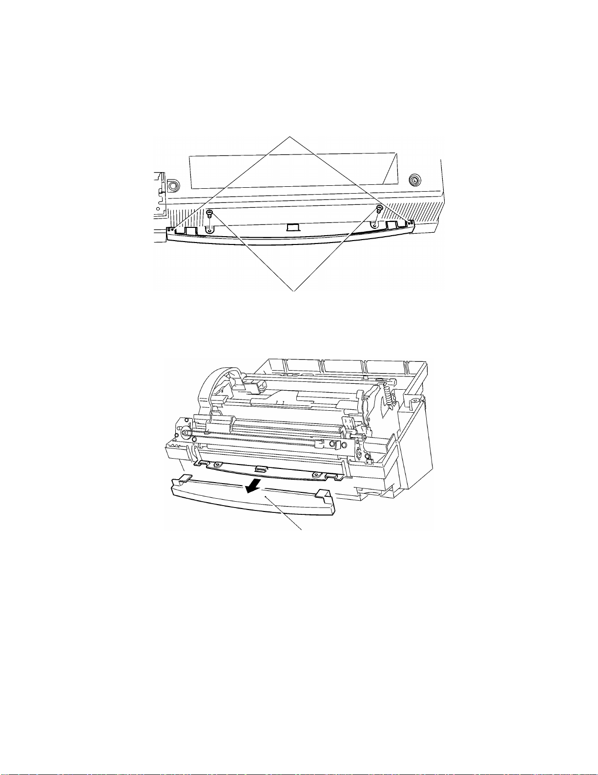
3.12 X-cutter
3.12.1 Removing the X-cutter Unit
1. Remove the two X-cutter screws. Lift up the X-cutter unit.
X-cutter screws
Fig. 3.12-1 Removing the X-cutter Unit
X-cutter unit
3.12.2 Disassembling the Tape Sensor Unit
1. Remove the leaf switch screw. Remove the leaf switch F assy.
2. Remove the sensor holder screw. Remove the tape sensor holder from the X-cutter
unit.
3. Remove the tape sensor lever from the tape sensor holder.
X-cutter unit
Tape sensor lever
Tape sensor holder
Leaf switch screw
Sensor holder screw
Fig. 3.12-2 Disassembling the Tape Sensor Unit
Leaf switch F assy
3-32
Page 53

3.13 Driving Roller Shaft
3.13.1 Removing the Driving Roller Shaft
1. Remove the driving roller C ring. Remove the gear 16M1 hook and driving roller
bearing. Take care not to open the driving roller C ring too far.
2. Remove the driving roller E ring. Remove the driving roller bearing.
3. Remove the driving roller shaft.
Driving roller C ring
Gear 16M1 hook
Bearing
Driving roller shaft
Driving roller E ring
Fig. 3.13-1 Removing the Driving Roller
3.14 Left Side of the Chassis
3.14.1 Removing the Gears
Remove the gears from the left side of the chassis in the sequence described below.
If the gear has one or two hooks, disengage the hooks from the locking groove in the
shaft before removing. Gear 20, removed at step 18 is fastened by a ring. Remove the
ring before removing the gear.
1. Gear 37 hook
2. TY-planet gear unit
Remove the TY-planet gear holder, before removing the felt, TY-idle gear, and TY-
spring washer from the shaft. Remove the TY-planet gear from the TY-planet gear
holder.
3. Gear 25 hook
4. Planet 20 hook (two)
Remove the planet 20 hook, before removing the felt, TY-planet gear holder, TY-spring
washer, and TY-planet gear.
Bearing
3-33
Page 54

5. Gear 36/12 hook
6. Gear 21
7. Gear 37 hook
8. Gear 21
9. Gear 40/16 hook (This is removed when removing the paper eject roller.)
10. Gear 21
11. Gear 20 (This is removed when removing the paper eject roller.)
12. Gear 60/20 hook
13. Gear 60/16M1
14. Gear 60/16
15. Gear 16M1
16. Gear 48/24
17. Gear 20
18. Gear 20
19. Gear 20
20. Gear 50
Planet 20 hook unit
Planet 20 hook
Planet gear holder
TY-spring washer
Gear 20 ring
Gear 37 hook
TY-planet gear
Felt
Gear 40/16 hook
Gear 36/12 hook
TY planet gear
TY planet gear holder
Gear 20
Gear 25 hook
Felt
TY-idle gear
Gear 60/16M1
Gear 60/20 hook
Gear 16M1
Gear 21
TY-planet gear unit
TY-spring washer
Fig. 3.14-1 Removing the Gears
Gear 50
Gear 37 hook
Gear 60/16
Gear 48/24
3-34
Page 55

3.14.2 Disassembling the Left Side of the Chassis
1. Release roller guide L from the boss hole. Incline the guide and remove it.
2. Remove the LF motor screw and TC/LF motor screw. Remove the LF motor.
Boss hole
Roller guide L
TC/LF motor screw
LF motor
LF motor screw
Fig. 3.14-2 Disassembling the Left Side of the Chassis
3-35
Page 56

3.15 Right Side of the Chassis
3.15.1 Disassembling the Right Side of the Chassis
1. Remove the leaf switch Y screw. Remove the leaf switch Y assy.
2. Release the Y-sensor lever hook and remove the Y-sensor lever.
3. Incline the edging saddle EDS-1 and remove it.
4. Release roller guide R from the boss hole. Incline the guide and remove it.
5. Remove the TY-planet gear holder, before removing the felt, TY-idle gear, and TYspring washer from the shaft. Take care not to damage the TY-planet gear holder
hooks by opening too far.
6. Remove the TY-planet gear from the TY-planet gear holder.
Roller guide R
Y-sensor lever hook
Y-sensor lever
TY-spring washer
Fig. 3.15-1 Disassembling the Right Side of the Chassis (1)
Edging saddle EDS-1
Leaf switch Y screw
Leaf switch Y assy
TY-idle gear
Felt
TY-planet gear
TY-planet gear holder
3-36
Page 57

7. Remove the two TC motor screws. Remove the TC motor.
TC motor
TC motor screws
Fig. 3.15-2 Disassembling the Right Side of the Chassis (2)
3.16 Lower Chassis
3.16.1 Removing the Left and Right Sides of the Chassis
Remove the six side chassis screws and remove the left and right sides of the chassis.
Side chassis screws
Fig. 3.16-1 Removing the Left and Right Sides of the Chassis
3-37
Page 58

3.16.2 Removing the Cassette Holder
1. Release the two side hooks fastening the cassette holder.
2. Flex the rear face of the cassette holder inward to release the two lugs. Remove the
cassette holder from the bottom chassis.
Hooks
Bottom chassis
Fig. 3.16-2 Removing the Cassette Holder
Lug
Cassette holder
3.16.3 Removing the Encoder (ENC) Sensor PCB
Remove the ENC sensor screw. Remove the ENC sensor assy.
ENC sensor screw
ENC sensor assy
Fig. 3.16-3 Removing the ENC Sensor PCB
3-38
Page 59

3.16.4 Removing the Cassette Detect Switch
Remove the leaf switch (SW) C screw. Remove the leaf switch C assy.
Leaf switch (SW) C screw
Leaf switch C assy
Fig. 3.16-4 Removing the Cassette Detect Switch
3-39
Page 60

Chapter 4.
REASSEMBLY PROCEDURES
Page 61

CONTENTS
Chapter 4. REASSEMBLY PROCEDURES
4.1 Safety Precautions ............................................................................................................4-1
4.2 Table of Tightening Torque...............................................................................................4-1
4.3 Lower Chassis...................................................................................................................4-2
4.3.1 Installing the Cassette Detect Switch....................................................................4-2
4.3.2 Installing the Encoder (ENC) Sensor PCB ...........................................................4-2
4.3.3 Installing the Cassette Holder...............................................................................4-3
4.3.4 Installing the Left and Right Sides of the Chassis................................................4-3
4.4 Right Side of the Chassis..................................................................................................4-4
4.4.1 Reassembling the Right Side of the Chassis........................................................4-4
4.5 Left Side of the Chassis ....................................................................................................4-6
4.5.1 Reassembling the Left Side of the Chassis..........................................................4-6
4.5.2 Installing the Gears...............................................................................................4-6
4.6 Driving Roller Shaft............................................................................................................4-9
4.6.1 Installing the Driving Roller Shaft..........................................................................4-9
4.7 X-cutter............................................................................................................................4-10
4.7.1 Reassembling the Tape Sensor Unit..................................................................4-10
4.7.2 Installing the X-cutter Unit...................................................................................4-10
4.8 Y-diversion Lever.............................................................................................................4-11
4.8.1 Reassembling the Y-diversion Lever Assy.........................................................4-11
4.8.2 Installing the Y-diversion Lever Assy..................................................................4-12
4.9 Paper Eject Roller............................................................................................................4-13
4.9.1 Installing the Paper Eject Roller Unit ..................................................................4-13
4.9.2 Installing the Paper Eject Sub-roller Unit............................................................4-15
4.9.3 Installing the Y-D Shaft .......................................................................................4-15
4.10 Paper Feed Roller ...........................................................................................................4-17
4.10.1 Installing the Paper Feed Roller Assy.................................................................4-17
4.10.2 Installing the Paper Feed Sub-roller Assy ..........................................................4-18
4.11 Sensor Frame and Y-cutter Arm L..................................................................................4-19
4.11.1 Reassembling the Y-cutter Arm L.......................................................................4-19
4.11.2 Reassembling the Sensor Frame .......................................................................4-20
4.11.3 Installing the Y-cutter Arm L................................................................................4-21
4.11.4 Installing the Sensor Frame................................................................................4-22
4.12 Roller Holder....................................................................................................................4-22
4.12.1 Reassembling the Roller Holder Assy ................................................................4-22
4.12.2 Installing the Roller Holder Assy.........................................................................4-24
4.13 Y-CA Chassis..................................................................................................................4-25
4.13.1 Reassembling the Y-CA Chassis Assy...............................................................4-25
4.13.2 Installing the Y-CA Chassis Assy........................................................................4-26
i
Page 62

ii
4.14 T-Chassis.........................................................................................................................4-27
4.14.1 Reassembling the T-Chassis Unit.......................................................................4-27
4.14.2 Installing the T-Chassis Unit...............................................................................4-28
4.15 PCBs................................................................................................................................4-29
4.15.1 Installing the Switch PCB Assy...........................................................................4-29
4.15.2 Installing the Jack PCB Assy..............................................................................4-30
4.15.3 Installing the Main PCB Assy..............................................................................4-30
4.16 Chassis............................................................................................................................4-31
4.16.1 Installing the Chassis Unit...................................................................................4-31
4.16.2 Installing the PE Sensor Unit..............................................................................4-32
4.16.3 Installing the Harness Connectors......................................................................4-33
4.17 Covers .............................................................................................................................4-33
4.17.1 Reassembling the Dial Switch Holder Assy B ....................................................4-33
4.17.2 Installing the Dial Switch Holder Assy B.............................................................4-35
4.17.3 Installing the Cover Switch Assy.........................................................................4-36
4.17.4 Installing the Front Cover....................................................................................4-37
4.17.5 Installing the Body Cover....................................................................................4-38
4.17.6 Installing the Paper Tray and Paper Guide.........................................................4-41
4.17.7 Installing the Sub-tray .........................................................................................4-42
4.17.8 Installing the Top Cover......................................................................................4-42
4.17.9 Installing the Trimmer Upper Cover....................................................................4-43
4.18 Installing the Film Cartridge.............................................................................................4-44
Page 63

1
4.1 Safety Precautions
• When conducting reassembly operations, place the unit on a grounded anti-static
sheet. LSI and other electronic components are sensitive to static electricity and
may be damaged if touched while charged.
• Before transporting a circuit board, wrap it in a conducting sheet such as aluminum
foil.
• When using a soldering iron or other heat-producing tool, ensure that heat does not
damage wires, circuit boards, or plastic parts such as covers.
• Take care not to lose small screws or washers removed when replacing parts.
• Tighten all screws to the torque specified in the table below.
4.2 Table of Tightening Torque
Name of Screw Qty. Screw Size Tightening Torque See
Leaf switch (SW) C screw 1
ENC sensor screw 1
Side chassis screw 6
TC/LF motor screw 2
Leaf switch Y screw 1
TC/LF motor screw 1
LF motor screw 1
X-cutter screw 2
Leaf switch screw 1
Sensor holder screw 1
Paper eject roller screw 1 TAPTITE,CUP M3 × 5 0.49 to 0.686N•m 4-14
Y-CA sensor screw 1
Sensor holder screw 1
Sensor frame screw 2
Y-CA motor screw 2
Y-CA pulley holder screw 1
Y-CA frame screw 2
Leaf switch TRI screw 1
Paper guide screw 1
Leaf switch TRG screw 1
T-chassis unit screw 2
Plate spring screw 1
Switch PCB screw A 2
Switch PCB screw B 3
Jack PCB screw 1
Main PCB screw 4
Cassette holder screw 4
Bottom cover screw B 2
Slide plate screw 1
Slide plate spring screw 1
SCREW FLANGED2.6 × 8
TAPTITE,BIND B M2.6 × 6
TAPTITE,CUP M3 × 5
SCREW,BIND M3 × 6
PAN-HEAD MACHINE SCREW M2.6 × 8
TAPTITE,CUP M3 × 6
TAPTITE,CUP M3 × 16
TAPTITE,CUP M 3 × 5
TAPTITE,PAN B M2 × 6
TAPTITE BIND B M2.6 × 6
TAPTITE,BIND B M2.6 × 6
TAPTITE,BIND B M2.6 × 6
TAPTITE,CUP M3 × 5
SCREW,FLANGED M2.6 × 5
TAPTITE,CUP M3 × 5
TAPTITE,CUP M3 × 5
TAPTITE,PAN B M2 × 6
SCREW,BIND M3 × 6
PAN-HEAD MACHINE SCREW M2.6 × 8
TAPTITE,CUP M3 × 5
TAPTITE,CUP M3 × 5
TAPTITE,BIND B M3 × 12
TAPTITE,BIND B M3 × 14
TAPTITE,BIND B M 3 × 8
TAPTITE,BIND B M3 × 8
TAPTITE,CUP B M4 × 12
TAPTITE,BIND B M3 × 8
TAPTITE,BIND B M3 × 8
SCREW,FLANGED M2.6 × 5
0.196 to 0.392N•m 4-2
0.196 to 0.392N•m 4-2
0.49 to 0.686N•m 4-3
0.49 to 0.686N•m 4-4
0.196 to 0.392N•m 4-5
0.49 to 0.686N•m 4-6
0.49 to 0.686N•m 4-6
0.49 to 0.686N•m 4-10
0.196 to 0.392N•m 4-10
0.686 to 0.882N•m 4-10
0.196 to 0.392N•m 4-19
0.196 to 0.392N•m 4-19
0.49 to 0.686N•m 4-22, 32
0.196 to 0.392N•m 4-25
0.49 to 0.686N•m 4-25
0.49 to 0.686N•m 4-26
0.196 to 0.392N•m 4-27
0.49 to 0.686N•m 4-27
0.196 to 0.392N•m 4-27
0.49 to 0.686N•m 4-28
0.49 to 0.686N•m 4-28
0.49 to 0.686N•m 4-29
0.49 to 0.686N•m 4-29
0.49 to 0.686N•m 4-30
0.49 to 0.686N•m 4-30
0.98 to 1.176N•m 4-31
0.49 to 0.686N•m 4-31
0.49 to 0.686N•m 4-34
0.196 to 0.392N•m 4-34
Page
4-
Page 64

2
Name of Screw Qty. Screw Size Tightening Torque See
Leaf switch R/L screw 2
Dial holder screw 2
Cover switch screw 1
Front cover screw 2 TAPTITE,BIND B M2.6X6 0.294 to 0.49N•m 4-37
Bottom cover screw A 2 TAPTITE,BIND B M3X12 0.196 to 0.392N•m 4-40
Trimmer cover screw 2
PAN-HEAD MACHINE SCREW M2.6 × 8
TAPTITE,BIND B M3 × 8
PHILLIPS PAN-HEAD TAPTILE B M2.6 ×
12
SCREW,BIND M3 × 6
0.196 to 0.392N•m 4-35
0.49 to 0.686N•m 4-35
0.49 to 0.686N•m 4-36
0.49 to 0.686N•m 4-43
Page
4.3 Lower Chassis
4.3.1 Installing the Cassette Detect Switch
Align the leaf switch C assy with the boss hole in the lower chassis and fasten it in
position with the leaf switch (SW) C screw. Take care not to deform the tip of the leaf
switch C assy during installation.
Leaf switch (SW) C screw
Lower chassis
Boss hole
Leaf switch C assy
Fig. 4.3-1 Installing the Cassette Detect Switch
4.3.2 Installing the Encoder (ENC) Sensor PCB
Align the ENC sensor assy with the two bosses. Fasten the assembly to the cassette
holder with the ENC sensor screw.
Fig. 4.3-2 Installing the ENC Sensor PCB
Bosses
ENC sensor assy
ENC sensor screw
4-
Page 65

3
4.3.3 Installing the Cassette Holder
Engage the two side hooks and four claws on the cassette holder with the bottom
chassis. Insert the two rear lugs into the slots to fasten the cassette holder.
Lug
Cassette holder
Claws
Hooks
Bottom chassis
Fig. 4.3-3 Installing the Cassette Holder
Slot
4.3.4 Installing the Left and Right Sides of the Chassis
Insert the two lugs on the left or right side of the chassis into the rectangular holes in the
lower chassis. Fasten each side chassis in position with the three side chassis screws.
Side chassis screws
Lower chassis
Lugs
Fig. 4.3-4 Installing the Left and Right Sides of the Chassis
4-
Page 66

4
4.4 Right Side of the Chassis
4.4.1 Reassembling the Right Side of the Chassis
1. Attach the TC motor with the two TC/LF motor screws.
TC motor
Fig. 4.4-1 Reassembling the Right Side of the Chassis (1)
TC/LF motor screws
4-
Page 67

5
2. Put the TY-spring washer, TY-idle gear, and felt (stick onto the TY-idle gear) on the
shaft.
3. Attach the TY-planet gear to the TY-planet gear holder. Put the TY-planet gear
holder on the shaft and push it until the hooks engage.
4. Incline the roller guide R and push the cut-out and align the roller guide R with the
boss hole A to engage with chassis R.
5. Incline the edging saddle EDS-1 and push it into position.
6. Align the Y-sensor lever hook with boss hole B in the chassis R and push it into
hooking position.
7. Align the leaf switch Y assy with the chassis R boss hole C and fasten it in position
with the leaf switch Y screw. Install the contacts of the leaf switch Y assy over the Ysensor lever.
Y-sensor lever
Boss hole B
Y-sensor lever hook
Roller guide R
Edging saddle EDS-1
Boss hole A
TY-planet gear
Leaf switch Y screw
Leaf switch Y assy
TY-spring washer
TY-idle gear
Boss hole C
Fig. 4.4-2 Reassembling the Right Side of the Chassis (2)
Felt
TY-planet gear holder
4-
Page 68

6
4.5 Left Side of the Chassis
4.5.1 Reassembling the Left Side of the Chassis
1. Fasten the LF motor with one TC/LF motor screw and one LF motor screw.
2. Incline the roller guide L. Insert the cut-out into chassis L and push it into place until
the hooks engage in the boss hole.
Roller guide L
Boss hole
TC/LF motor screw
LF motor
Fig. 4.5-1 Reassembling the Left Side of the Chassis
4.5.2 Installing the Gears
Install the gears at the left side of the chassis in the sequence described below.
If the gear (or holder) has one or two hooks, push it into place until the hooks engage in
the locking groove in the shaft.
Gear 20, installed at step 3, is fastened by a ring.
1. Gear 50
2. Gear 20
3. Gear 20
4. Gear 20
5. Gear 48/24 (48-tooth side against chassis)
6. Gear 16M1
7. Gear 60/16 (16-tooth side against chassis)
8. Gear 60/16M1 (16-tooth side against chassis)
9. Gear 60/20 hook
10. Gear 20
11. Gear 21
12. Gear 40/16 hook
LF motor screw
4-
Page 69

7
13. Gear 21
14. Gear 37 hook
15. Gear 21
16. Gear 36/12 hook
17. Planet 20 hook (two)
Attach the TY-planet gear to the planet gear holder. Put the TY-spring washer, planet
gear holder, felt (stick onto the TY-planet gear holder), and planet 20 hook on the
shaft.
18. Gear 25 hook
19. TY-planet gear unit
Attach the TY-planet gear to the TY-planet gear holder. Put the TY-spring washer, TY-
idle gear, felt (stick onto the TY-idle gear), and TY-planet gear holder on the shaft.
20. Gear 37 hook
Gear 20 ring
Gear 20
Gear 25 hook
Gear 60/16M1
Gear 60/20 hook
Gear 50
Gear 60/16
Gear 48/24
TY-planet gear
Planet 20 hook unit
Planet 20 hook
Planet gear holder
TY-spring washer
TY-planet gear holder
Gear 37 hook
Felt
Gear 40/16 hook
Gear 36/12 hook
TY-planet gear
Gear 16M1
Felt
TY-idle gear
TY-spring washer
Fig. 4.5-2 Installing the Gears (1)
Gear 21
Gear 37 hook
TY-planet gear unit
4-
Page 70

8
Gear 60/20 hook
Gear 50
Gear 60/16M1
Gear 16M1
Gear 25 hook
Gear 36/12 hook
Gear 20
Gear 40/16
hook
Gear 60/16
Gear 48/24
TY-planet gear
Gear 20
TY-planet gear
TY-idle gear
Planet gear 20 hook
Gear 37 hook
TY-planet gear
Gear 21
Gear 36/12
hook
Fig. 4.5-3 Installing the Gears (2)
4-
Page 71

9
4.6 Driving Roller Shaft
4.6.1 Installing the Driving Roller Shaft
1. Insert the semicircular end of the driving roller shaft into the hole in chassis L.
2. Put the driving roller bearing from the left and attach it to chassis L. (Align the lug on
the bearing with the cut-out in the chassis.)
3. Insert the right end of the driving roller shaft into the hole in chassis R.
4. Put the driving roller bearing from the right and attach it to chassis R. (Align the lug
on the bearing with the cut-out in the chassis.)
5. Fasten the right end of the driving roller shaft with the driving roller E ring.
6. Put the gear 16M1 hook on the left end of the driving roller shaft and fasten it with
the driving roller C ring. Take care not to open the driving roller C ring too far.
Driving roller C ring
Gear 16M1 hook
Driving roller
bearing
Driving roller shaft
Driving roller E ring
Fig. 4.6-1 Installing the Driving Roller Shaft
Driving roller bearing
4-
Page 72

4.7 X-cutter
4.7.1 Reassembling the Tape Sensor Unit
1. Fasten the leaf switch F assy to the tape sensor holder with the leaf switch screw.
2. Attach the tape sensor lever to the tape sensor holder.
3. Attach the tape sensor holder to the X-cutter unit with the sensor holder screw.
X-cutter unit
Tape sensor lever
Tape sensor holder
Sensor holder screw
Fig. 4.7-1 Reassembling the Tape Sensor Unit
4.7.2 Installing the X-cutter Unit
Leaf switch F assy
Leaf switch screw
Install the X-cutter unit into the chassis unit from above. Fasten it in position with the
two X-cutter screws.
X-cutter screws
X-cutter unit
Fig. 4.7-2 Installing the X-cutter Unit
4-10
Page 73

4.8 Y-diversion Lever
4.8.1 Reassembling the Y-diversion Lever Assy
1. Hold the Y-cutter guide shaft with the two rings at the right end. Insert the left end
into Y-cutter guide L and the right end into Y-cutter guide R.
2. Insert the Y-cutter guide shaft through the holes in the Y-diversion lever. Fasten with
the two Y-cutter guide shaft rings.
3. Stick new Y-diversion lever film on the Y-diversion lever, if it requires replacing.
Y-cutter guide L
Y-cutter guide shaft
Y-cutter guide R
Y-cutter guide shaft rings
Y-diversion lever
Fig. 4.8-1 Reassembling the Y-diversion Lever Assy
Y-diversion lever film
4-11
Page 74

4.8.2 Installing the Y-diversion Lever Assy
1. Mount the Y-diversion lever assy on the X-cutter unit by inserting the left end into
chassis L then the right end into chassis R.
X-cutter unit
Fig. 4.8-2 Installing the Y-diversion Lever Assy 1
2. Press each of the two Y-cutter assy’s against the Y-diversion lever assy and move it
in the direction of arrow 1 up to the position of the Y-cutter guide L/R.
3. Install the Y-cutter guides by lifting the tab on each Y-cutter assy in the direction of
arrow 2, then pushing in the direction of arrow 3 to engage the hook.
Y-diversion lever assy
1
2
3
Y-cutter assy
2 3
1
Y-cutter guide L
Y-cutter guide R
Fig. 4.8-3 Installing the Y-diversion Lever Assy 2
4-12
2
3 1
Page 75

4.9 Paper Eject Roller
4.9.1 Installing the Paper Eject Roller Unit
1. Temporarily remove gear 40-16 and gear 20 when installing the paper eject roller
unit, as these can interfere with the installation.
2. Hold the paper eject roller unit with the end where the gears mount at the left. Insert
the left end into the hole in chassis L, then the right end into the hole in chassis R.
Paper eject roller unit
Gear 40-16 hook
Gear 20
Fig. 4.9-1 Installing the Paper Eject Roller Unit (1)
4-13
Page 76

3. Insert the left and right paper eject roller bearings into the chassis L/R. The paper
eject roller bearings can only be inserted if the lugs on the bearings are aligned with
the grooves in the chassis.
4. Turn the paper eject roller bearing L counterclockwise to the boss hole to insert it in
the chassis left side. Likewise, turn the paper eject roller bearing R clockwise to the
boss hole to insert it in the chassis right side.
5. After inserting the paper eject roller bearing R in the chassis right side, fasten it in
position with the paper eject roller screw.
6. Align the gear 16 hook with the semicircular end of the paper eject roller unit and
push the gear until the hook engages.
7. Replace gear 40-16 hook and gear 20 which were temporarily removed previously.
Gear 16 hook
Paper eject roller bearing
Paper eject roller unit
Gear 20
Gear 40-16 hook
Paper eject roller screw
Paper eject roller bearing
Fig. 4.9-2 Installing the Paper Eject Roller Unit (2)
4-14
Page 77

4.9.2 Installing the Paper Eject Sub-roller Unit
1. Orient the left paper eject shaft holder L (narrow) and right paper eject shaft holder
R (wide) with the flat face inward and attach them to the paper eject sub-roller unit.
2. Attach the paper eject shaft holders L/R attached to paper eject sub-roller unit to the
paper eject roller shaft in the chassis.
Paper eject shaft holders L/R
Fig. 4.9-3 Installing the Paper Eject Sub-roller Unit
Paper eject roller unit
Paper eject sub-roller unit
4.9.3 Installing the Y-D Shaft
1. Align the Y-D shaft with the long semicircular end to the right. Align the Y-cutter
cams L/R with each semicircular end of the Y-D shaft and attach them to the shaft.
Y-cutter cam L
Fig. 4.9-4 Installing the Y-D Shaft (1)
Y-D shaft
Y-cutter cam R
4-15
Page 78

2. Insert the Y-D shaft (with cams) first into chassis R, then into chassis L. The Y-D
LF motor mounting
shaft should be inserted behind the paper eject shaft holders L/R.
3. Put the Y-driving gear onto the right semicircular end of the Y-D shaft. Next put the
Y-gear 40-20 on this shaft and push the gear until the hook engages.
4. Attach the left and right Y-extension springs (L/R). Attach the Y-extension spring L
(the longer one) to the LF motor mounting screw.
5. Attach the left and right paper eject sub-roller springs.
Paper eject sub-roller springs
Fig. 4.9-5 Installing the Y-driving Shaft (2)
Y-driving gear
shaft holder L
Y-D shaft
Y-extension spring L
Y-cutter cam L/R
screw
Paper eject
shaft holder
R
Y-gear 40-20
Y-extension spring R
4-16
Page 79

4.10 Paper Feed Roller
4.10.1 Installing the Paper Feed Roller Assy
1. Insert the bearings into the chassis L/R.
2. Attach the left and right rod holders to the paper feed roller assy with the hooks
inward.
Paper feed roller assy
Bearings
Rod holders
Fig. 4.10-1 Installing the Paper Feed Roller Assy (1)
3. Hold the paper feed roller assy with the semicircular end to the right. Insert the right
bearing, then insert the left bearing. Fasten by attaching the paper feed roller ring to
the shaft.
4. Align the gear 16 hook with the semicircular end of the paper feed roller assy and
push the gear until the hook engages.
Paper feed roller ring
Bearings
Paper feed roller assy
Gear 16 hook
Fig. 4.10-2 Installing the Paper Feed Roller Assy (2)
4-17
Page 80

4.10.2 Installing the Paper Feed Sub-roller Assy
1. Hold the paper feed sub-roller assy with the semicircular end to the right. Push
through the left and right rod holders and engage the paper feed roller grooves in the
bearings.
Paper feed sub-roller assy
Rod holders
Bearings
Fig. 4.10-3 Installing the Paper Feed Sub-roller Assy (1)
2. Align the lower boss of the left and right rod holders with the slots in the chassis L/R.
3. Attach the left and right paper feed shaft spring (L)/R.
4. Align the gear 16 hook with the semicircular end of the paper feed sub-roller assy
and push the gear until the hook engages.
Paper feed sub-roller assy
Gear 16 hook
Paper feed shaft spring R
Fig. 4.10-4 Installing the Paper Feed Sub-roller Assy (2)
4-18
Slot Paper feed shaft spring
Page 81

4.11 Sensor Frame and Y-cutter Arm L
4.11.1 Reassembling the Y-cutter Arm L
1. Fasten the Y-CA sensor to the photosensor (PS) PCB holder with the Y-CA sensor
screw.
2. Put the PL detect lever on the photosensor (PS) PCB holder shaft. Turn the PL
detect lever to the position where the sensor is cut off and push it until the hook
engages.
3. Align the boss hole in the photosensor (PS) PCB holder with the Y-cutter arm L and
fasten it in position with the sensor holder screw.
Y-CA sensor
Sensor holder screw
Photosensor (PS) PCB holder
Boss hole
Hook
Y-CA sensor screw
PL detect lever
Y-cutter arm L
Fig. 4.11-1 Reassembling the Y-cutter Arm L
4-19
Page 82

4.11.2 Reassembling the Sensor Frame
1. Attach the paper sensor harness assy (flat cable) to the FPC holder A and FPC
holder B.
2. Insert the hooks on FPC holder A into slots A in the sensor frame. Attach FPC
holder A by moving it in the direction of the arrow until the hook tip engages in the
groove.
3. Insert the hooks on FPC holder B into slot B and the end hole in the sensor frame.
Attach FPC holder B by moving it in the direction of the arrow until it engages with
the boss holes.
4. Stick new sensor crank protect film aligned with the sensor frame boss, if the film
requires replacing.
FPC holder A
Sensor frame
Slot A
Hook tip
Hooks A
Groove
Bosses
Boss hole
Slot B
End hole
Sensor crank
protect film
Paper sensor harness assy
Fig. 4.11-2 Reassembling the Sensor Frame
FPC holder B
Hooks B
4-20
Page 83

4.11.3 Installing the Y-cutter Arm L
1. Engage the lug on Y-cutter guide L with the groove in Y-cutter arm L. Insert the Ycutter arm shaft in Y-cutter arm L.
2. Insert the Y-cutter arm shaft in holes in the chassis L/R. Fasten with the two arm
shaft rings.
Groove
Lug
Y-cutter arm L
Y-cutter arm shaft
Arm shaft rings
Fig. 4.11-3 Installing the Y-cutter Arm L
4-21
Page 84

4.11.4 Installing the Sensor Frame
1. Align the left end of the sensor frame with boss A on the side of chassis R. Align the
right end of the sensor frame above boss B on chassis L.
2. Insert the paper sensor crank through the cut-out in the in the sensor crank
protective film and engage it with the paper feed roller unit shaft. Pass the bottom
edge of the sensor crank protective film between the paper feed sub-roller and the
paper feed roller.
3. Fasten into place with the two sensor frame screws.
Boss A
Sensor frame screws
Boss B
Paper sensor crank
Fig. 4.11-4 Installing the Sensor Frame
Paper feed sub-roller
Paper feed
roller
Sensor crank
protective film
4.12 Roller Holder
4.12.1 Reassembling the Roller Holder Assy
1. Put the release plates L/R onto the roller holder shaft and fasten them with the
release plate rings.
2. Insert the round part of the press roller springs into part A of the roller holder assy.
Make sure that the long leg of each press roller spring faces outward.
3. Attach the sub-roller bearings L/R and tape hold bearings L/R to the sub-roller assy.
Install the tape hold shaft into the semicircular holes in the tape hold bearings L/R.
4. Align the sub-roller bearings L/R with the boss holes and attach them to the release
plates L/R.
5. Hook the left and right extension springs 0.4 in the holes in the tape hold bearings
L/R, then install by hooking the springs on part B of the roller holder assy.
6. Put the lock lever spring R on the set button R and attach them to the lock lever R
through the roller holder assy. In this operation, engage the lock lever spring R on
the lock lever R as shown at “E” in the figure below, then turn the lock lever R until
hook C fits the cut-out A.
Sensor frame
4-22
Page 85

Boss hole
Release plate
ring
bearing L
7. Put the interference board, set button L, and lock lever spring L onto the lock lever
shaft. Pass the shaft through the hole in the left side of the roller holder assy.
8. Insert the lock lever shaft in the semicircular hole in lock lever R. Insert hook B of
lock lever L from the position of cut-out A as with lock lever R, and turn to fasten in
position.
9. Fasten the lock lever springs L/R inside the lock levers L/R.
10. Fasten the left and right side covers L/R to the roller holder by engaging the
individual two hooks A to it.
Hooks A
Lock
Hook B
lever L
Side cover L
Release plate L
Press roller
spring L
Tape hold
bearing LSub-roller
Tape hold shaft
Set button L
Sub-roller assembly
Extension
spring 0.4
Cut-out A
Lock lever
spring L
Roller holder
Lock lever
shaft
Interference
board
Extension
spring 0.4
Lock lever
spring R
Cut-out A
Set button
R
Lock lever R
Roller holder
Set button R
Lock lever spring R
E
Part B
Lock lever R
Hook C
Hook A
Side
cover R
Hook A
Tape hold bearing R
Sub-roller bearing R
Fig. 4-12-1 Reassembling the Roller Holder Assy
Boss hole
Release plate R
Press roller spring R
Release plate ring
4-23
Page 86

4.12.2 Installing the Roller Holder Assy
1. Move the Y-cutter arm L as far as possible to the left.
2. Insert the chassis unit R boss shaft into the hole in the roller holder assy, then insert
the chassis unit L boss shaft. Attach the roller holder rings to the left and right boss
shafts to fasten the roller holder assy in position.
3. Lift up the roller holder assy and attach the roller holder spring.
Chassis unit L
boss shaft
Roller holder assy
Y-cutter arm L
Roller holder rings
Fig. 4.12-2 Installing the Roller Holder Assy
Chassis unit R boss shaft
Roller holder spring
4-24
Page 87

4.13 Y-CA Chassis
Y-CA driving pulley ring
Y-CA motor
A B Y-CA pulley holder
Shaft
holder screw
Y-CA Chassis
4.13.1 Reassembling the Y-CA Chassis Assy
1.Attach the Y-CA motor with the two Y-CA motor screws.
2.Put the Y-CA driving pulley on the Y-CA chassis shaft and fasten it with the Y-CA
driving pulley ring.
3.Insert the shaft of the Y-CA idle pulley into slot A of the Y-CA pulley holder. Push the
Y-CA idle pulley in the direction of arrow A to fasten it in position.
4.Insert lug A of the Y-CA pulley holder into slot B in the Y-CA chassis. Push the Y-CA
idle pulley holder in the direction of arrow A to fasten it in position.
5.Push the Y-CA pulley holder in the direction of arrow A and put the Y-CA timing belt
over the Y-CA idle pulley. Put the timing belt over the Y-CA driving pulley.
6.Slide the Y-CA pulley holder in the direction of arrow B to tension the Y-CA timing belt
and tighten the Y-CA pulley holder screw. Y-CA Adjust the timing belt tension to
0.784 to 1.37 N.m
Y-CA driving pulley
Y-CA motor screws
Y-CA timing belt
Y-CA idle pulley
Y-CA pulley
Shaft
Lug A
Anti-static brush
Slot B Slot A
Fig. 4.13-1 Reassembling the Y-CA Chassis Assy
4-25
Page 88

4.13.2 Installing the Y-CA Chassis Assy
1.Align the Y-CA chassis assy with the positioning hook and the two bosses on chassis
L.
Positioning
hook
Bosses
Fig. 4.13-2 Installing the Y-CA Chassis Assy (1)
2.Attach the Y-CA timing belt to the attachment position on the Y-cutter arm L.
3.Fasten the Y-CA unit with the two Y-CA frame screws.
4.Attach the Y-extension spring L.
Y-CA
timing belt
Y-extension
spring L
Y-cutter arm L
Y-CA timing belt
Y-CA frame screws
Y-CA chassis assy
Fig. 4.13-3 Installing the Y-CA Chassis Assy (2)
4-26
Page 89

4.14 T-Chassis
C D C
4.14.1 Reassembling the T-Chassis Unit
1.Install the T-idle gear and T-gear 35-14 on the T-chassis. Put the T-cam shaft through
the T-cam gear and engage the hook on the T-cam gear with the groove on the Tcam shaft.
2.Align the T-sensor lever with boss hole A. Insert lug A through the slot and rotate in
the direction of the arrow to fasten it in position.
3.Align the leaf switch TRG assy with boss hole B. Fasten the leaf switch TRG assy
above the T-sensor lever with the leaf switch TRG screw.
4.Align the T-paper guide with the two boss holes C and fasten with the paper guide
screw.
5.Insert the T-cutter upper assy into the T-cutter holder and fasten it with the T-cutter
stopper.
6.Align the lug at each side of the T-cutter holder with the grooves in the T-paper guide.
Install the T-cutter upper assy with the blade facing down.
7.Push the switch lever until it engages with the shaft hook on the T-paper guide.
8.Align the leaf switch TRI assy with boss hole D and fasten it in position with the leaf
switch TRI screw.
9.Attach the T-push spring and T-cam roller to T-lever 2. Assemble T-lever 2 to T-lever
1 to form the T-lever unit.
10.Pass the T-lever shaft through the holes in the T-chassis and the T-lever unit. Open
the T-paper guide hook and engage it with the groove in the T-lever shaft to install
the T-lever unit.
Leaf switch TRI screw
T-cutter holder
Paper
guide
screw
T-cutter stopper
T-cutter upper assy
T-sensor lever
Leaf switch TRG screw
Leaf switch TRG assy
Leaf switch TRI assy
Switch lever
Shaft hook
T-paper guide
T-lever 1
T-push spring
T-lever 2
Lug “A”
T-cutter
Hook
T-chassis
T-lever unit
T cam roller
B
Slot
T-gear 35-14
T-idle gear
T-lever shaft
Hook
T-cam gear
T-cam shaft
Fig. 4.14-1 Reassembling the T-Chassis Unit
4-27
Page 90

4.14.2 Installing the T-Chassis Unit
1.Align the T-chassis unit with the two bosses.
Bosses
Fig. 4.14-2 Installing the T-Chassis (1)
2.Fasten the T-chassis unit with the two T-chassis screws.
3.Align the plate spring with the boss and fasten it with the plate spring screw, such that
it holds T-gear 35-14 in position.
T-chassis unit
Plate spring screw
T-chassis unit
T-gear 35-14
Plate spring
T-chassis screw
Fig. 4.14-3 Installing the T-Chassis Unit (2)
4-28
Page 91

4.15 PCBs
4.15.1 .Installing the Switch PCB Assy
1.Turn the body cover upside-down, and attach the start switch B,start key film, start key
actuator, two-connection switch, and power switch.
Two connection switch
Start switch B
ig. 4.15-1 Installing the Switch PCB Assy (1)
Power switch
2.Align the switch PCB assy 1 with the two bosses. Fasten it in position with the two
switch PCB screws A and three switch PCB screws B.
Switch PCB screws A
Switch PCB assy 1
Switch PCB screws B
Boss es
Fig. 4.15-2 Installing the Switch PCB Assy (2)
4-29
Page 92

4.15.2 Installing the Jack PCB Assy
Align the jack PCB assy 1 with the boss and fasten it in position with the jack PCB
screw.
Jack PCB screw
Boss
Fig. 4.15-3 Installing the Jack PCB Assy
4.15.3 Installing the Main PCB Assy
Ferrite core
Jack PCB assy 1
1.Align the Main PCB assy 1 with the two bosses and fasten it in position with the four
main PCB screws.
2.Attach the power harness assy (red/black CN13) to the Main PCB assy 1.
Main PCB screws
Power harness assy
Main PCB
assy 1
Main PCB screws
Bosses
Fig. 4.15-4 Installing the Main PCB Assy
4-30
Page 93

4.16 Chassis
4.16.1 Installing the Chassis Unit
1.Align the chassis unit with the two bosses on the bottom cover and fasten it in position
with the four cassette holder screws.
cassette holder screws
Fig. 4.16-1 Installing the Chassis Unit (1)
2.Attach the chassis unit using the two bottom cover screws B and the spring washers in
the bottom cover.
Bottom cover
Bottom cover screws B
Fig. 4.16-2 Installing the Chassis Unit (2)
4-31
Page 94

3.Remove the sensor frame screw from the sensor frame. Attach the ground wire and
fasten it with the sensor frame screw.
Ground wire
Fig. 4.16-3 Installing the Chassis Unit (3)
4.16.2 Installing the PE Sensor Unit
1.Engage the tip of the PE sensor unit with the paper sensor crank. Attach the PE
sensor unit to the paper feed roller, such that the sensor is located vertically above
the paper sensor crank. Take care not to damage the tip of the PE sensor unit
during installation.
2.Open the bottom cover bearing supports outward and mount the PE sensor unit in the
bearing supports.
Sensor frame
Sensor frame screw
PE sensor unit
PE sensor unit
Paper sensor crank
Fig. 4.16-4 Installing the PE Sensor Unit
4-32
Paper feed roller
Paper sensor crank
Bearing supports
Page 95

4.16.3 Installing the Harness Connectors
Attach the 12 harness connectors to the MAIN PCB. Do not attach the power harness
assy (red/ black CN13).
Power harness assembly
Yellow (CN12)
Yellow, blue, white, red, gray (CN11)
Black (CN10)
Fig. 4.16-5 Installing the Harness Connectors
4.17 Covers
White (CN9)
Orange (CN15)
Blue (CN8)
Red (CN4)
White (CN3)
White (CN7)
Red (CN6)
Black (CN5)
Flat cable
4.17.1 Reassembling the Dial Switch Holder Assy B
1.Put the dial lock arm on the dial S holder assy shaft. Engage lug A with the dial S
holder assy.
Dial lock arm
Lug A
Fig. 4.17-1 Reassembling the Dial Switch Holder Assy B (1)
Dial S holder assy
4-33
Page 96

2.Align slide plate 2 with the boss on slide plate 1B and fasten it with the slide plate
screw.
Slide plate screw
Slide plate 2
Slide plate 1B
Bosses
Fig. 4.17-2 Reassembling the Dial Switch Holder Assy B (2)
3.Engage the slide plate 1B hook and bosses A with the slots in the dial S holder assy.
Ensure that slide plate 1B is positioned relative to the dial lock arm as shown in
detail A.
4.Align the plate spring with bosses B and fasten it in position with the slide plate spring
screw.
Plate spring
Detail A
Slide plate spring screw
Bosses A
Slide plate 1B
Hook
Dial S holder assy
Bosses B
Fig. 4.17-3 Reassembling the Dial Switch Holder Assy B (3)
4-34
Page 97

5.Align the leaf switch R assy (red CN2) and the leaf switch L assy (white CN3) with the
boss holes and fasten them in position with the two leaf switch R/L screws.
6.Pull the plate spring in the direction of the arrow. Insert the dial switch B such that the
indicator is positioned between the two leaf switches.
Indicator
Dial switch B
Fig. 4.17-4 Reassembling the Dial Switch Holder Assy B (4)
4.17.2 Installing the Dial Switch Holder Assy B
1.Align the dial switch holder assy with the boss under the body cover and fasten it in
position with the two dial holder screws.
2.Attach the leaf switch R assy (red CN2) and leaf switch L assy (white CN3) harness
connectors to the switch PCB.
3.Install the switch harness assy (CN1) to the switch PCB.
4.Attach the dial lock arm spring between the dial lock arm and the lug on the body
cover.
Leaf switch R/L screws
Leaf switch L assy
(white CN3)
Leaf switch R assy
(red CN2)
Boss holesPlate spring
Dial holder screws
Dial switch
holder assy B
Boss
Fig. 4.17-5 Installing the Dial Switch Holder Assy B
Leaf switch L assy
4-35
Leaf switch R assy
Dial lock arm spring
Body cover lugDial lock arm
Page 98

4.17.3 Installing the Cover Switch Assy
1.Align the cover switch assy with the boss hole and fasten it in position with the cover
switch screw.
2.Connect the cover switch unit harness connector (yellow CN4) to the switch PCB.
Cover switch screw
Cover switch assy
Front
Boss hole
Harness connector
Fig. 4.17-6 Installing the Cover Switch Assy
4-36
Page 99

4.17.4 Installing the Front Cover
1.Align the front cover with the angle of the cover front face and insert parts A into parts
B. Push until the hooks at each side of the front cover engage.
Parts A
Parts B
Front cover
Fig. 4.17-7 Installing the Front Cover (1)
2.Fasten the two front cover screws under the bottom cover.
Front cover screws
Fig. 4.17-8 Installing the Front Cover (2)
4-37
Page 100

4.17.5 Installing the Body Cover
1.Pass all the harnesses through the hooks in the bottom cover.
2.Connect the switch harness assy (white CN1) to the MAIN PCB.
Fig. 4.17-9 Installing the Body Cover (1)
Fig. 4.17-10 Installing the Body Cover (2)
Switch harness assy
4-38
 Loading...