

Page 1

SERVICE MANUAL
MODEL: LX-1200/LX-300
Page 2

COOL LAMINATOR
SERVICE MANUAL
MODEL: LX-1200/LX-300
Page 3

Unauthorized copying of all or part of the contents of this manual is prohibit ed.
The contents of this manual may change without notice.
Page 4

INTRODUCTION
This Service Manual describes the Cool Laminator LX-1200/LX-300 specifications, operating
principles of the mechanisms, disassembly and reassembly procedures, and maintenance and
troubleshooting procedures.
This Service Manual is intended for use by trained technicians. It is not intended f or use by the
user.
The manual is divided into the following chapters.
Chapter 1. Specifications
Chapter 2. Mechanisms
Chapter 3. Disassembly Procedures
Chapter 4. Reassembly Procedures
Chapter 5. Electronic Controllers
Chapter 6. Maintenance
Chapter 7. Troubleshooting
Appendix Main PCB Circuit Diagram
Page 5

Chapter 1.
SPECIFICATIONS
Page 6

i
CONTENTS
Chapter 1. SPECIFICATIONS
1.1 Mechanical Specifications................................................................................................. 1-1
1.1.1 Appearance........................................................................................................... 1-1
1.1.2 Operating Panel....................................................................................................1-2
1.1.3 Indicators...............................................................................................................1-2
1.2 Electrical Specifications ....................................................................................................1-2
1.2.1 Power Supply........................................................................................................1-2
Page 7
1.1 Mechanical Specifications
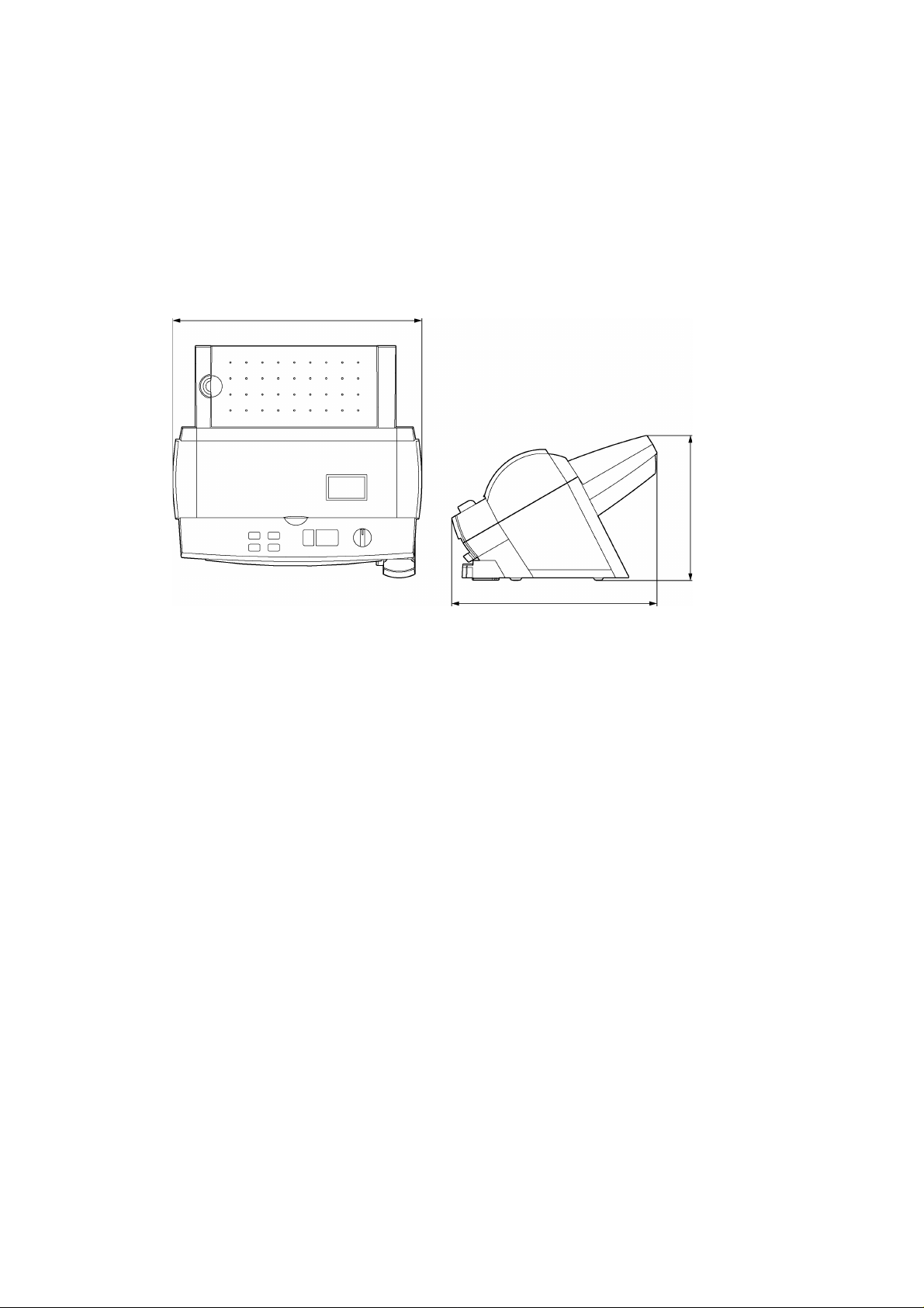
1.1.1 Appearance
[1] External dimensions (W x D x H) 468 mm x 387 mm x 273 mm
[2] Weight Approx. 8.3 kg (main unit only)
468 mm
273 mm
Fig. 1.1-1 Appearance
387 mm
1-1
Page 8
1-2
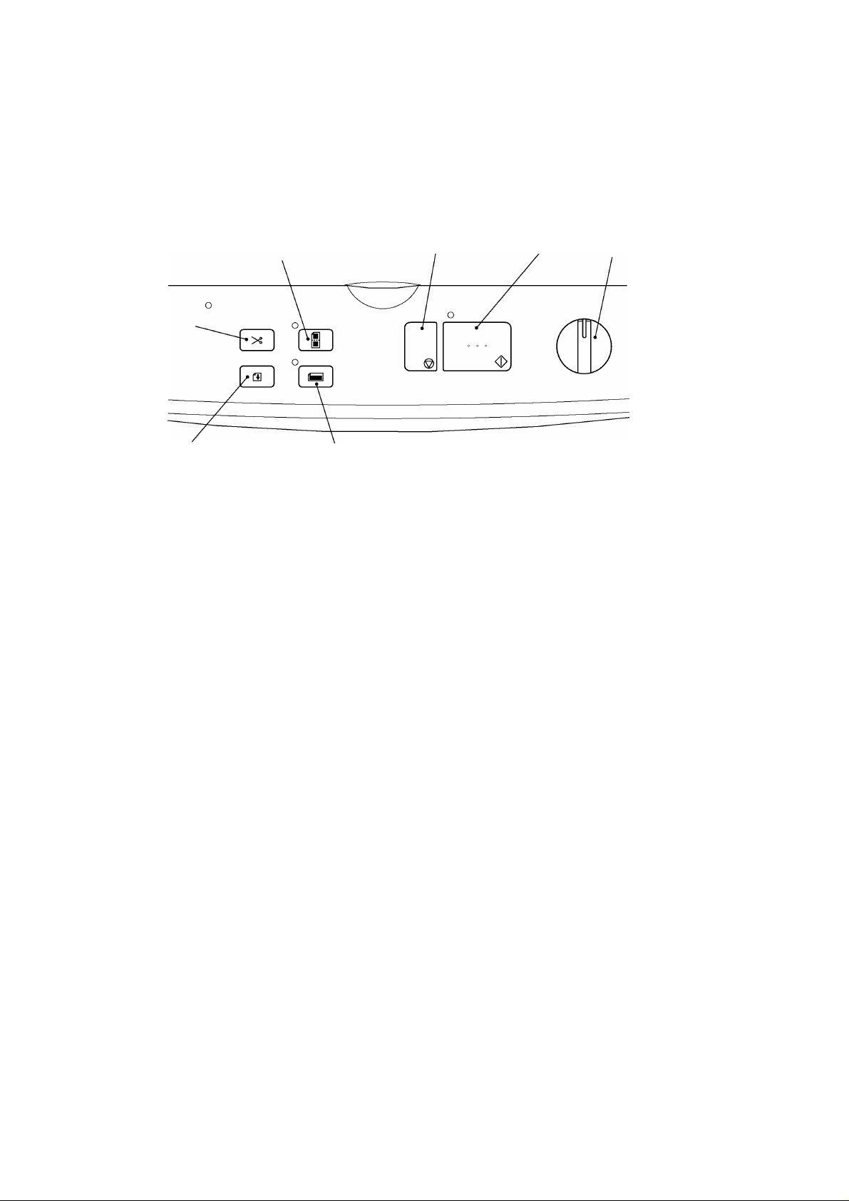
1.1.2 Operating Panel
P
C
C
S
S
[1] Number of Keys 7 (Start key, Stop key, Cut key, Feed key,
Extra border key, Continuous key, Cutting mode selector)
[2] Key Arrangement
Cut key
Feed key
1.1.3 Indicators
[1] Positions Start key LED (green)
Continuous key LED (green)
Extra border key LED (green)
Error LED (red)
ontinuous key
top ke y
Extra border key
Fig. 1.1-2 Key Arrangement
tart key
ower switch
utting mode selector
1.2 Electrical Specifications
1.2.1 Power Supply
[1] Power supply Commercial power supply (locally available power supply).
Converted to DC by the AC adaptor.
Page 9

Chapter 2.
MECHANISMS
Page 10

i
CONTENTS
Chapter 2. MECHANISMS
2.1 Mechanical Operating Principles......................................................................................2-1
2.1.1 Description of Mechanisms (Border Mode)..........................................................2-1
2.1.2 Feed and Compression Mechanisms...................................................................2-2
2.1.3 Cutter Mechanism (Border Mode) ........................................................................2-5
2.1.4 Paper Size Detector Mechanism..........................................................................2-7
2.1.5 Trimming Mechanism........................................................................................... 2-9
Page 11
2.1 Mechanical Operating Principles
E
C
D
R
P
P
P
s
R
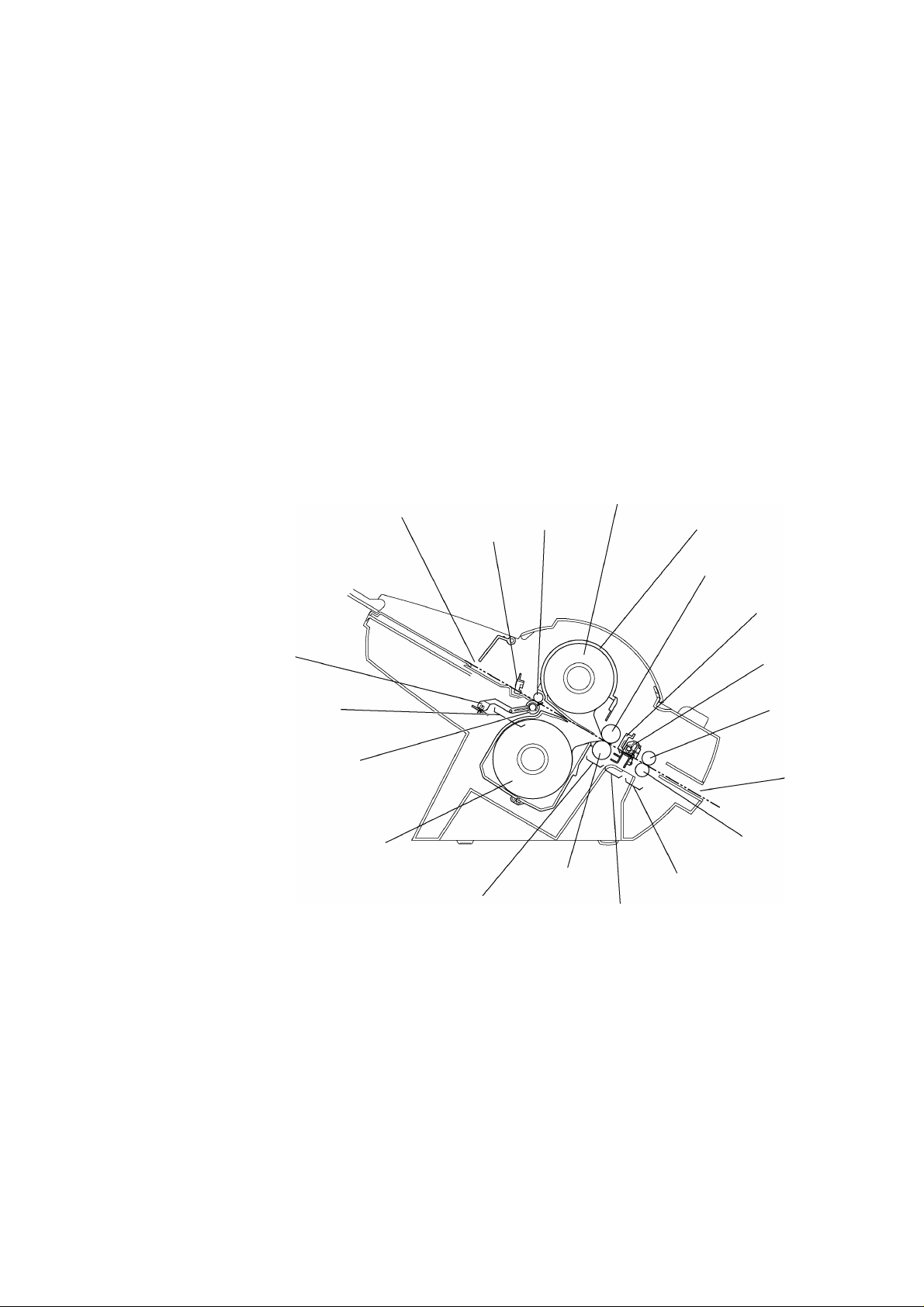
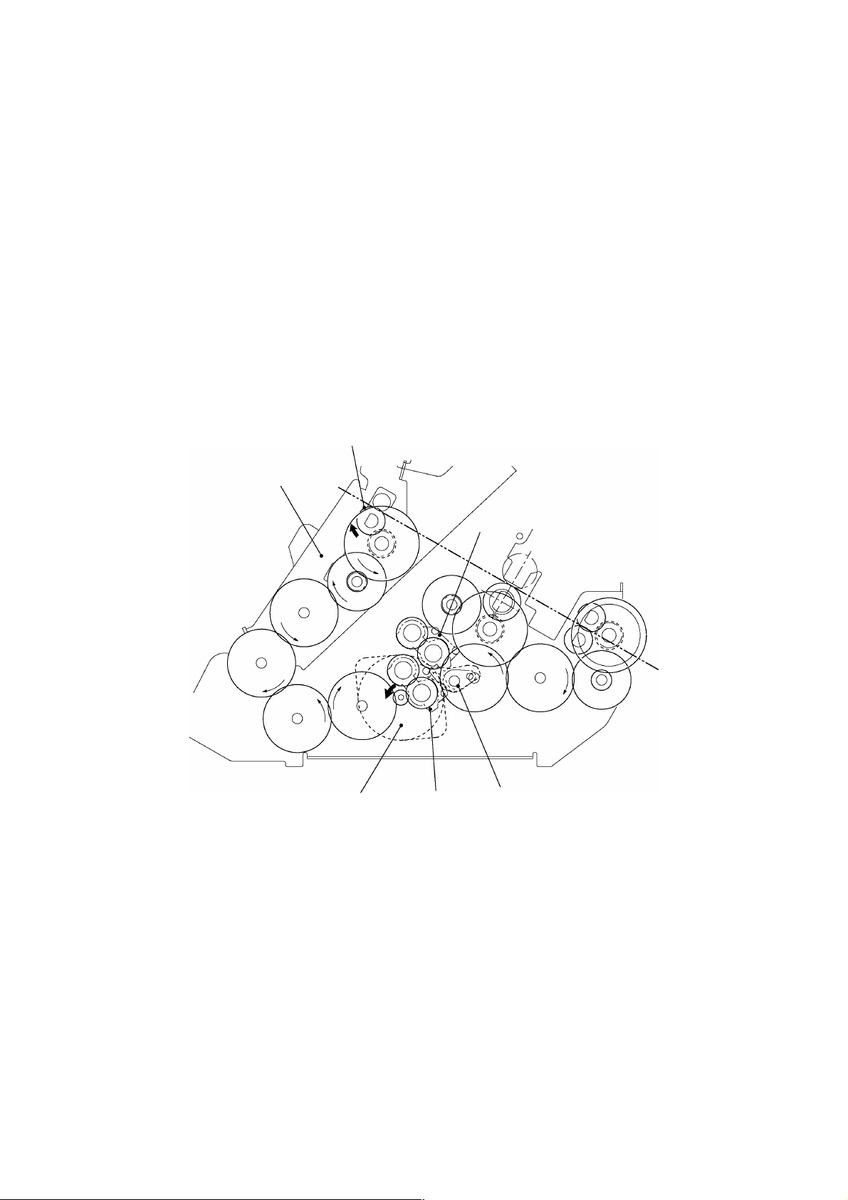
2.1.1 Description of Mechanisms (Border Mode)
1. When a document is inserted into the paper loading gate, the paper feed rollers feed
it to the driving roller.
2. As the document passes between the paper feed rollers, the paper size detector
determines its size (length and width).
3. When the document passes between the film cartridges it is sandwiched between
the upper and lower films in the compression-feed area, where the films and
document are compressed between the driving roller and sub-roller.
4. The compressed document and film is fed to the cutting area, where it is cut to the
document size detected by the paper size detector with borders added. It is t hen
transported to the next stage.
5. The laminated document is fed out of the eject gate by the paper eject rollers.
Paper length detector
Paper loading area
Paper feed roller
aper loading gate
oll film (lower)
Compression-feed area
aper width de tector
aper feed
ub-roller
riving roller
oll film (upper)
Film cartridge
Sub-roller
Y-cutter blad e
X-cutter unit
Paper eject roller
ject gate
Paper eject sub-roller
Ejecting area
utting area
Fig. 2.1-1 Description of Mechanis m s
2-1
Page 12

2-2
2.1.2 Feed and Compression Mechanisms
G
L
G
D
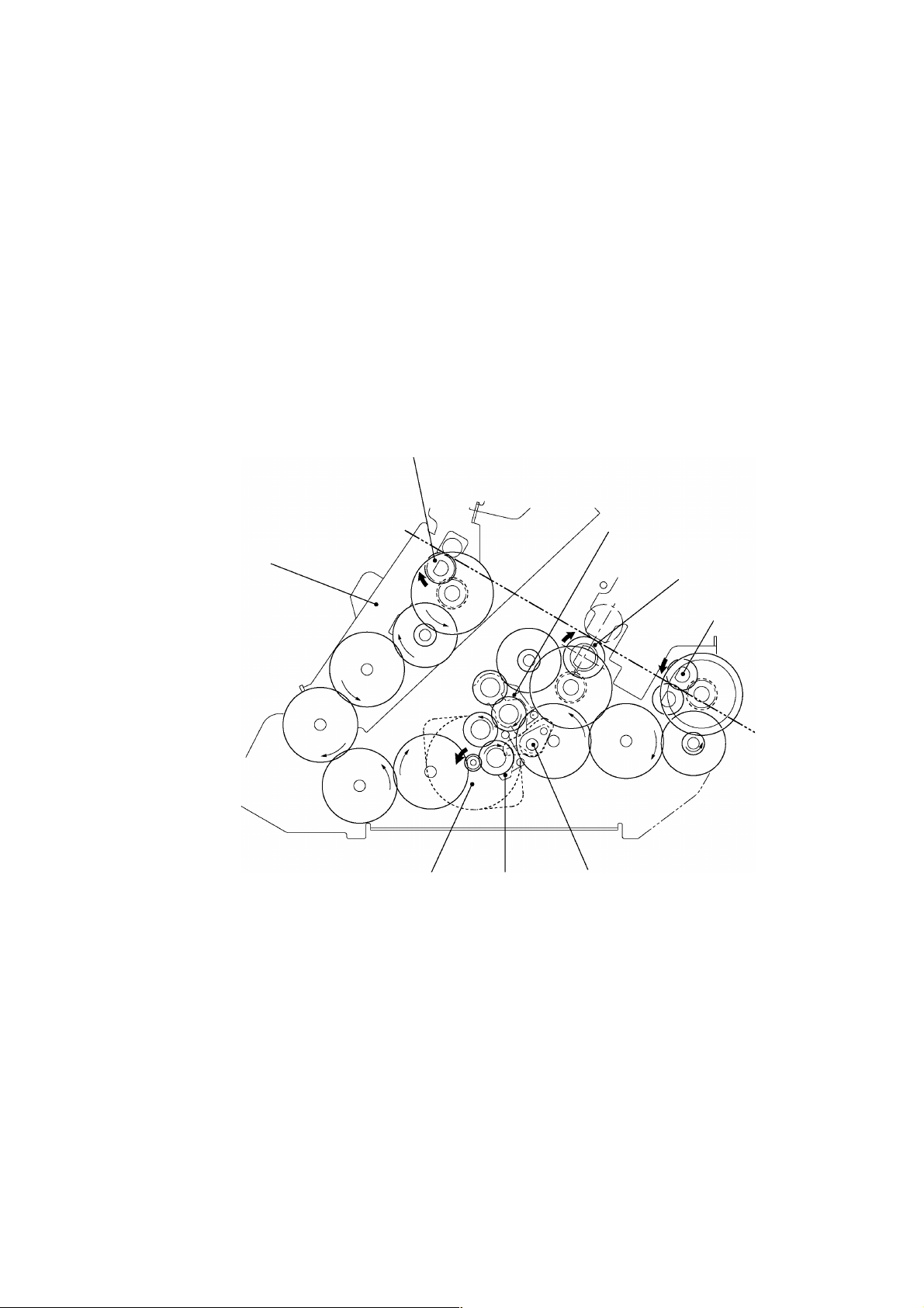
The feed and compression mechanism controls the motor drive to feed the document
into the film cartridge, compression-feed the films, and eject t he laminat ed document .
The operation is basically divided into three separate operations: feeding a document
into the Film cartridge, compression-feeding the films, and ejecting the laminat ed
document.
Normal Mode
When documents are laminated one at a time (that is, not in the Continuous mode), t he
lamination operation comprises the operations A and B below.
A. Feeding document into Film cartridge and ejecting the laminated document
S
1. The SG motor mounted at the right of the chassis runs to rotate the Control cam
gear (also mounted at the right of the chassis) to its prescribed position.
2. As the Control cam gear rotates, the LF change shaft is rotated to its prescribed
position by the cam on the Control cam gear.
3. A cam is mounted on the LF motor end of the LF change shaft (at the left of t he
chassis). As the LF change shaft rotates, this cam rotates the t wo Gear holders
at the left of the chassis, which transmit t he LF mot or drive as shown in t he
diagram.
4. As a result of steps 1 to 3 above, the drive is transmitted to the Paper f eed roller
and Paper eject roller. The document is fed into the Film cartridge by the Paper
feed roller as the LF motor rotates. After the trailing edge has been cut by the X
cutter, the laminated document is ejected by the Paper eject roller.
ear holder
Paper feed roller
riving roller
Paper eject roller
LF moto r
ear holder
Fig. 2.1-2 Operation when Feeding Document into the Fil m Cart ri dge or when Ejecting a Laminated Document
F change shaft
Page 13
2-3
B. Compression-feeding the films
G
L
G
S
1. The SG motor mounted at the right of the chassis runs to rotate the Control cam
gear (also mounted at the right of the chassis) to its prescribed position.
2. As the Control cam gear rotates, the LF change shaft is rotated to its prescribed
position by the cam on the Control cam gear.
3. A cam is mounted on the LF motor end of the LF change shaft (at the left of t he
chassis). As the LF change shaft rotates, this cam rotates the t wo Gear holders
at the left of the chassis, which transmit t he LF mot or drive as shown in t he
diagram.
4. As a result of steps 1 to 3 above, the drive is transmitted to the Driving roller t hat
compresses the films. During this operation, the Paper feed roller and Paper
eject roller rotate continuously to feed in documents and eject laminated
documents.
Paper feed roller
ear holder
Paper feed holder
LF moto r
Fig. 2.1-3 Operation during Film Compression-Feed
ear holder
F change shaft
Driving roller
Paper eject roller
Page 14
2-4
Continuous Mode
G
L
P
G
When the second or subsequent document are inserted in the Continuous mode, the
operation C described below feeds the documents to the prescribed position.
C. Feeding Document Only into Film Cartridge
S
1. The SG motor mounted at the right of the chassis runs to rotate t he Control cam
gear (also mounted at the right of the chassis) to its prescribed position.
2. As the Control cam gear rotates, the LF change shaft is rotated t o it s prescribed
position by the cam on the Control cam gear.
3. A cam is mounted on the LF motor end of the LF change shaft (at the left of t he
chassis). As the LF change shaft rotates, this cam rotates the t wo Gear holders at
the left of the chassis, which transmit the LF mot or drive as shown in t he diagram.
4. As a result of steps 1 to 3 above, the drive is transmitted t o t he Paper f eed roller
only. A document is fed into the Film cartridge by the Paper feed roller as the LF
motor rotates.
aper feed roller
Paper feed holder
ear holder
LF moto r
ear holder
F change shaft
Fig. 2.1-4 Operation when Feeding Document into the Fil m Cart ri dge i n the Continuous Mode
Page 15
2-5
2.1.3 Cutter Mechanism (Border Mode)
C
Y
Y
The cutter mechanism cuts the laminated document to the size of the document plus an
added border. Both edges of the films are cut to suit the width of the document and the
leading edge and trailing edge are cut according to the document length.
Y-Cutter Vertical Drive Operation
S
The SG motor drive rotates the Control cam gear to its prescribed position. This
rotation is transmitted via the YC lift arm and YC lift shaf t t o rotate the Y-diversion
lever and set the Y cutter to the cutting position.
Y-diversion lever
-cutter blade
ontrol cam gear
YC lift shaft
C lift arm
Fig. 2.1-5 Y-Cutter Vertical Driv e Operat i on
SG motor
Page 16
2-6
Cutting Leading and Trailing Edges (X-cutter Mechanism)
D
F
R
D
D
S
R
S
A
A
F
S
1. All the rollers which feed the document stop when the cut position at the leading
edge of the document reaches the cutting position of the rotary cutt er and f ixedblade cutter.
2. The DC motor rotates to drive the carriage in the X-cutter assy via the spiral
mechanism (not illustrated).
3. As the carriage makes a reciprocal movement, the rotary cutter attached to the
carriage moves against the fixed cutter to cut the compressed leading edge of
the document.
4. The rotation of the rollers which feed the document restarts when the cutting of
the leading edge is complete. Then, when the cut position at t he trailing edge of
the document reaches the cutting position of the rotary cutter and f ixed-blade
cutter, the feed rollers stop again.
5. The document trailing edge is cut in the same way as the leading edge by a
reciprocal movement of the rotary cutter attached to the carriage.
6. The rotation of the Paper eject roller and Paper feed roller restarts to feed the
laminated document from the eject gate after the cut t ing of t he t r ailing edge is
complete. (In this timing, the driving roller does not rotate.)
Document
Paper eject roller
Paper eject sub-roller
ection A-A'
Paper eject roller
Paper eject sub-roller
Fig. 2.1-6 Cutting Leading and Trailing Edges (X-cutter Mechanism)
Carriage
'
otary cutter
ixed cutter
Sub-roller
riving roller
Carriage
ixed cutter
otary cutter
ub-roller
ocument
riving roller
Page 17
2-7
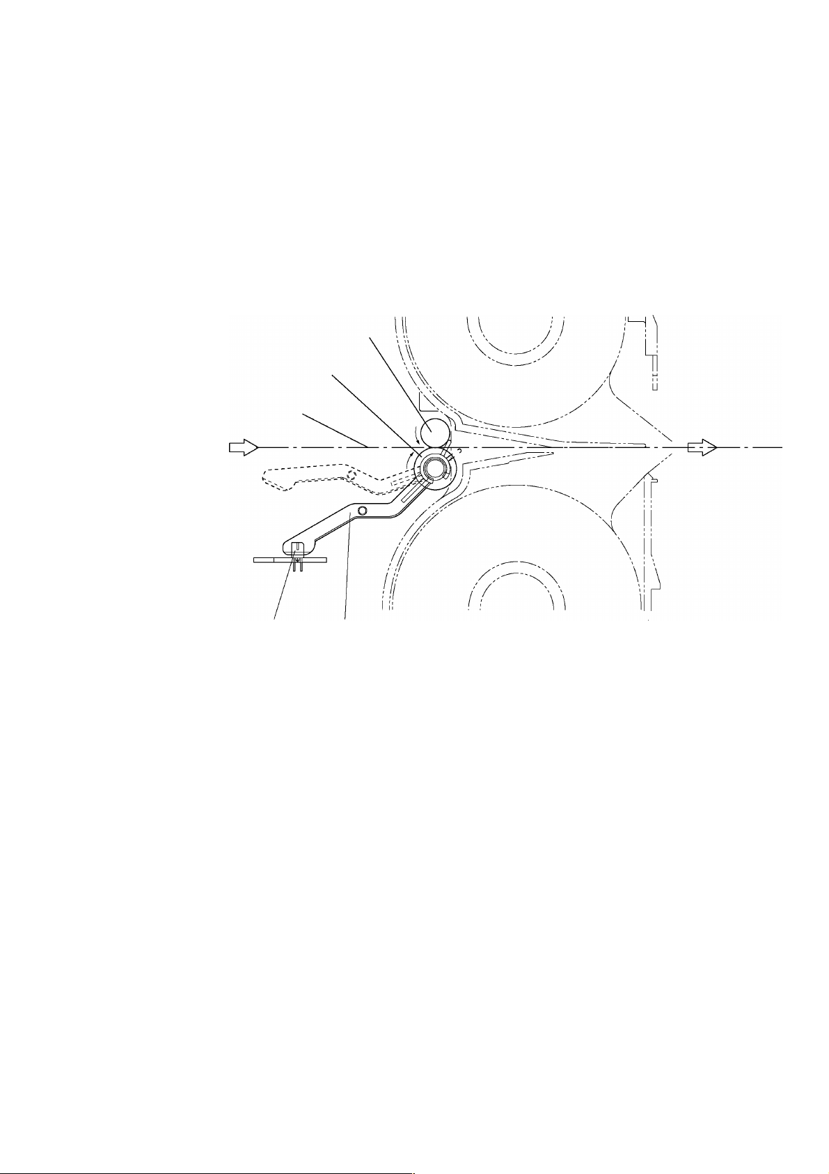
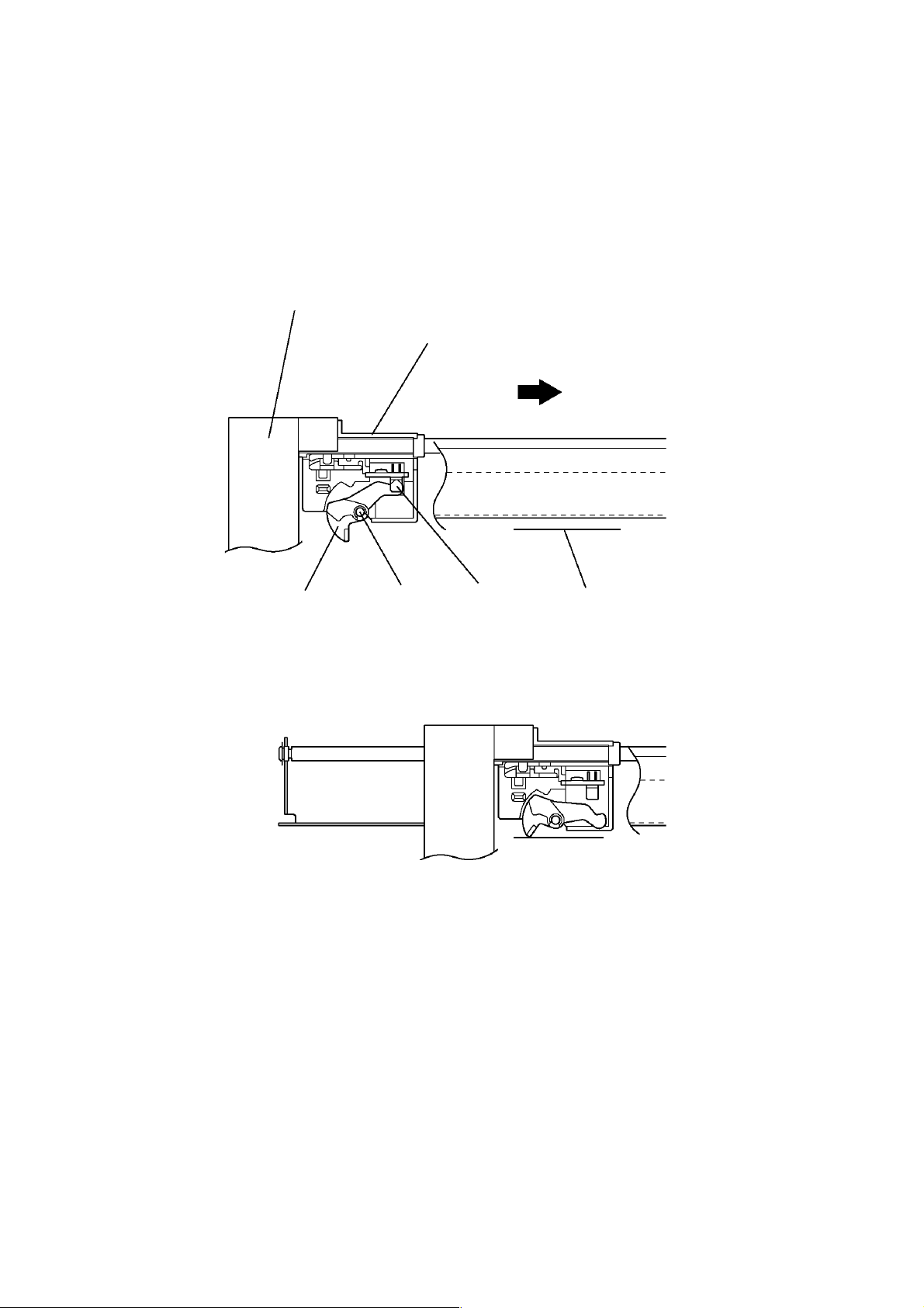
2.1.4 Paper Size Detector Mechanism
Paper Length Detection
S
1. When the leading edge of the document passes between the Paper feed rollers,
the Actuator top operates about the pivot to turn on t he Paper sensor and det ect
the document leading edge.
2. When the trailing edge of the document passes out of the Paper feed r oller s, t he
Actuator top reverts to its original position to turn off t he Paper sensor and
detect the document trailing edge.
Paper feed sub-roller
Paper feed roller
Document feed surface
Paper sensor
Actuator top
Fig. 2.1-7 Paper Length Detection
Page 18
2-8
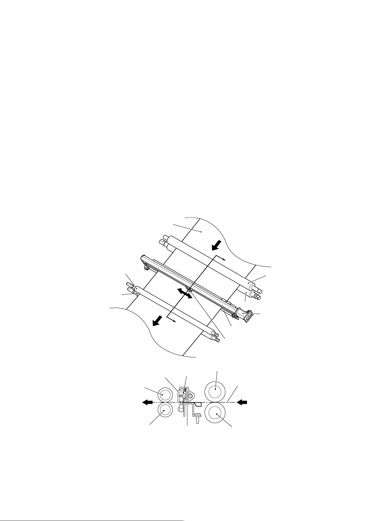
Paper Width Detection (Y-CA sensor)
Y
Y
Y
D
S
1. As the Y-cutter arm (Y-CA sensor carriage) moves in the direction of the arrow,
the document contacts the Actuator Y, which rotat es about t he pivot t o swit ch of f
the Y-CA sensor (photosensor).
2. When the Y-CA sensor turns off, the Y-cutter arm movement stops and this
position is detected as the document width.
-cutter a rm
sensor carriage
Actuator Y
Photosensor ON status
∗
Photosensor OFF status
∗
Pivot
Fig. 2.1-8 Paper Width Detection
-CA sensor
ocument
Page 19
2-9
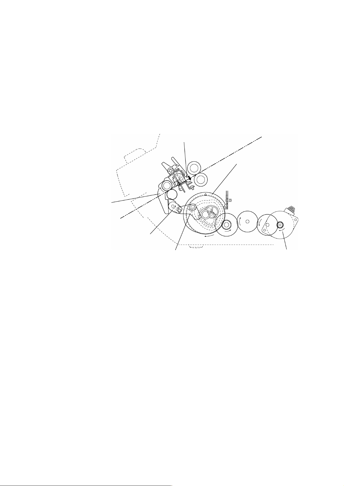
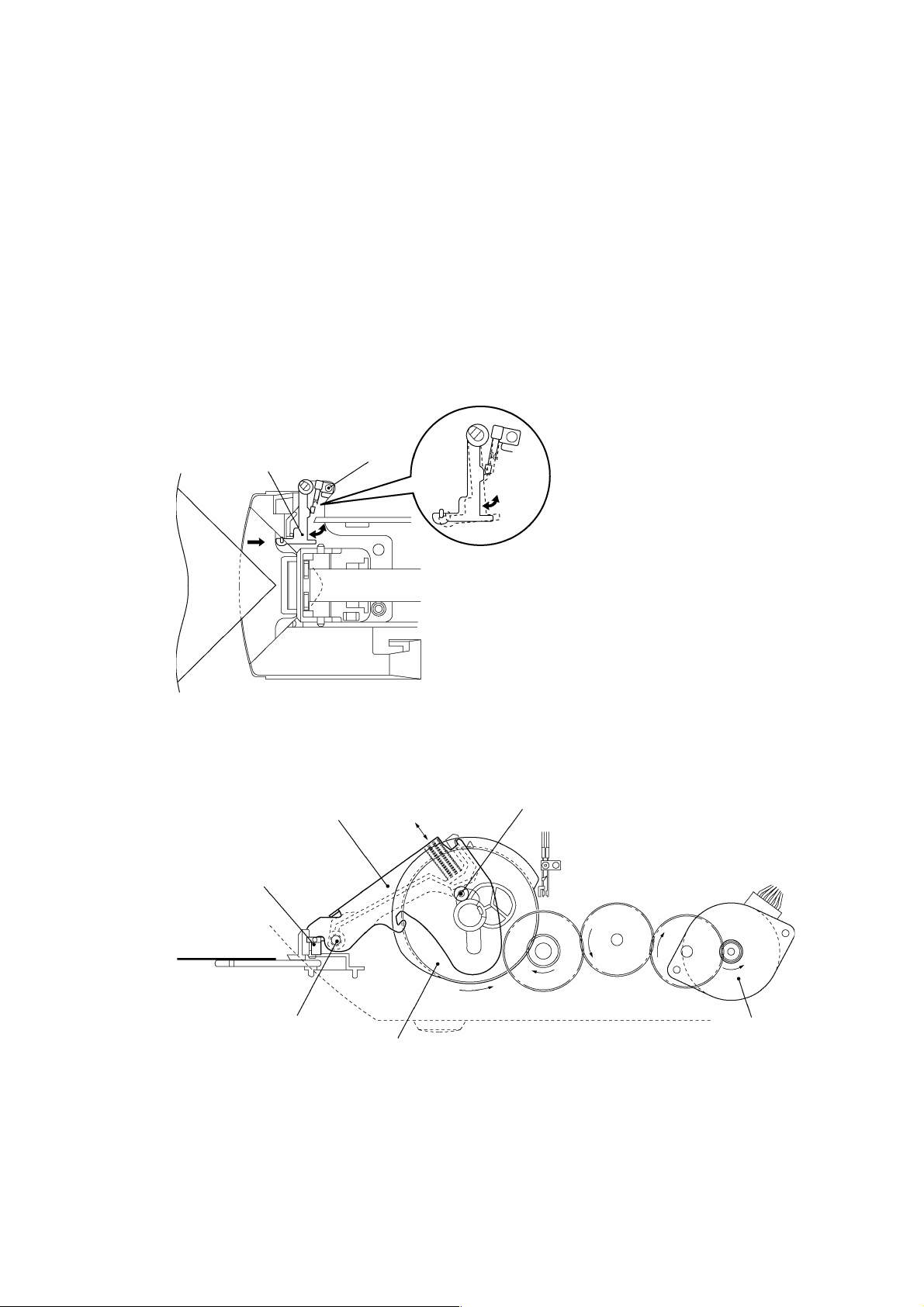
2.1.5 Trimming Mechanism
T
T
1. When a corner of the laminated document is inserted over the T-cutter plate, t he Tsensor lever operates a leaf switch (TRI) that detects the document.
2. When the document is detected, the motor gear of the SG Motor rot at es f r om it s
reference position to the prescribed position to rotate the Control cam gear in the
direction of the arrow (counterclockwise) via a series of gears.
3. Rotation of the Control cam gear forces the T-cam roller to move vertically, such
that T-lever also moves vertically, rotating around its pivot.
4. As T-lever moves vertically, the T-cutter assy mounted on the end of T-lever moves
up and down, trimming the corner of the laminated document into a rounded radius.
Leaf switch
T-sensor lever
-cam roller
-lever
T-cutter unit
Pivot
Control cam gea r
SG motor
Fig. 2.1-9 Trimming Mechanism
Page 20

Chapter 3.
DISASSEMBLY PROCEDURES
Page 21

CONTENTS
Chapter 3. DISASSEMBLY PROCEDURES
3.1 Safety Precautions............................................................................................................3-1
3.2 Removing the Film Cartridge ............................................................................................3-1
3.3 Covers ...............................................................................................................................3-2
3.3.1 Removing the Trimmer Cover ..............................................................................3-2
3.3.2 Removing the Top Cover B ..................................................................................3-3
3.3.3 Removing the Sub-tray.........................................................................................3-4
3.3.4 Removing Paper Tray A and Paper Guide...........................................................3-4
3.3.5 Removing the Body Cover....................................................................................3-5
3.3.6 Removing the Front Cover.................................................................................... 3-7
3.3.7 Removing Paper Tray B .......................................................................................3-8
3.3.8 Removing the Back Cover....................................................................................3-8
3.3.9 Removing the Cover Switch .................................................................................3-9
3.3.10 Removing the Dial Switch Holder Assy B ..........................................................3-10
3.3.11 Removing the Push Switch Assy........................................................................ 3-11
3.4 Chassis Assy................................................................................................................... 3-12
3.4.1 Removing the Harness Connectors ...................................................................3-12
3.4.2 Removing the PST PCB (Paper Sensor PCB)................................................... 3-13
3.4.3 Removing the Chassis Assy...............................................................................3-14
3.5 PCBs ............................................................................................................................... 3-16
3.5.1 Removing the Main PCB ....................................................................................3-16
3.5.2 Removing the Jack PCB Assy............................................................................ 3-16
3.5.3 Removing the SW PCB Assy .............................................................................3-17
3.6 X-cutter Unit ....................................................................................................................3-18
3.6.1 Removing the X-cutter Unit.................................................................................3-18
3.6.2 Removing the Leaf Switch F Assy......................................................................3-18
3.7 Y-CA Chassis Assy and Y-cutter Arm............................................................................ 3-19
3.7.1 Removing the Y-CA Chassis Assy.....................................................................3-19
3.7.2 Removing the Y-CA Motor..................................................................................3-20
3.7.3 Removing the Y-cutter Arm ................................................................................3-20
3.8 Y-sensor Rail Unit ...........................................................................................................3-21
3.8.1 Removing the Y-sensor Rail Unit .......................................................................3-21
3.8.2 Disassembling the Y-sensor Rail Unit................................................................3-22
3.9 Roller Holder Assy ..........................................................................................................3-23
3.9.1 Removing the Roller Holder Assy ......................................................................3-23
3.10 Paper Feed Roller...........................................................................................................3-24
3.10.1 Removing the Paper Feed Holder Assy.............................................................3-24
3.11 Left Side of the Main Chassis .........................................................................................3-25
i
Page 22

ii
3.11.1 Removing the LF Motor ......................................................................................3-25
3.11.2 Removing the Gears...........................................................................................3-26
3.12 Right Side of the Main Chassis.......................................................................................3-27
3.12.1 Removing the Right Side of the Chassis............................................................3-27
3.12.2 Removing the YC Lift Shaft and LF Change Shaft ............................................3-28
3.13 Paper Eject Roller ...........................................................................................................3-30
3.13.1 Removing the Paper Eject Roller Unit................................................................3-30
3.14 Y-diversi on Lever............................................................................................................3-31
3.14.1 Removing the Y-diversion Lever Assy ...............................................................3-31
3.15 Trimming Mechanism...................................................................................................... 3-32
3.15.1 Disassembling the Trimming Mechanism ..........................................................3-32
3.16 Driving Roller ...................................................................................................................3-32
3.16.1 Removing the Driving Roller...............................................................................3-32
3.17 Main Chassis B ...............................................................................................................3-33
3.17.1 Removing the Main Chassis B ...........................................................................3-33
3.17.2 Removing the Cassette Holder...........................................................................3-34
3.17.3 Removing the ENC Sensor PCB........................................................................3-34
3.17.4 Removing the Main Chassis L, R, and F............................................................3-35
Page 23
3-1
3.1 Safety Precautions
T
•
When conducting disassembly operations, place the unit on a grounded anti-static
sheet. LSI and other electronic components are sensitive to static electricity and
may be damaged if touched while charged.
•
Before transporting a circuit board, wrap it in a conducting sheet such as aluminum
foil.
•
When using a soldering iron or other heat-producing tool, ensure that heat does not
damage wires, circuit boards, or plastic parts such as covers.
•
Take care not to lose small screws or washers removed when replacing parts.
•
As a safety precaution, wear gloves when conducting disassembly operations.
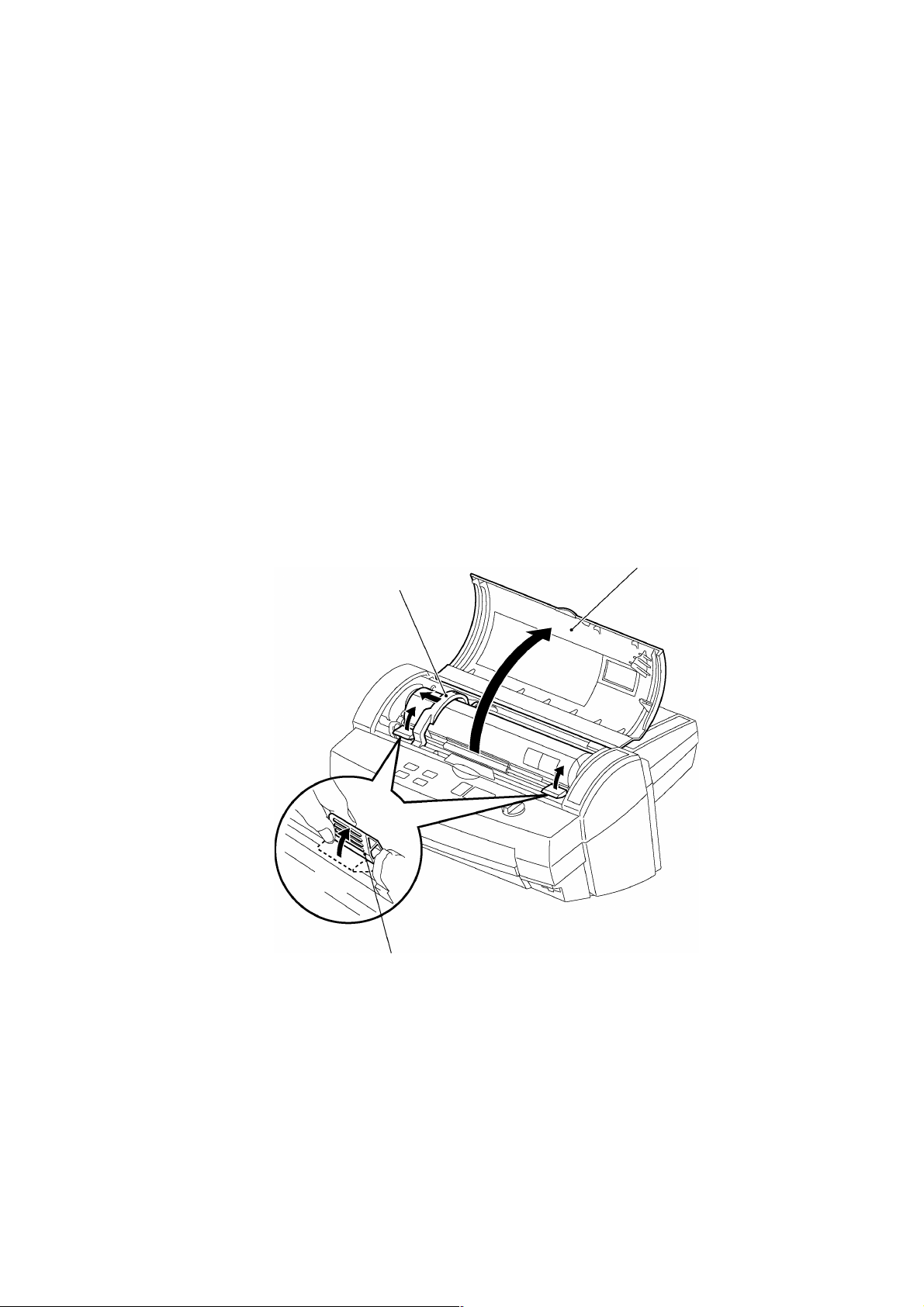
3.2 Removing the Film Cartridge
1. Open the top cover and move the Y-cutter arm as far as possible to the left.
2. Push the Set buttons R/L in the direction indicated by the arrow t o unlock t he Roller
holder assy.
Y-cutter arm
op cover
Set butto n R/L
Fig. 3.2-1 Removing the Film Cartridge 1
Page 24
3-2
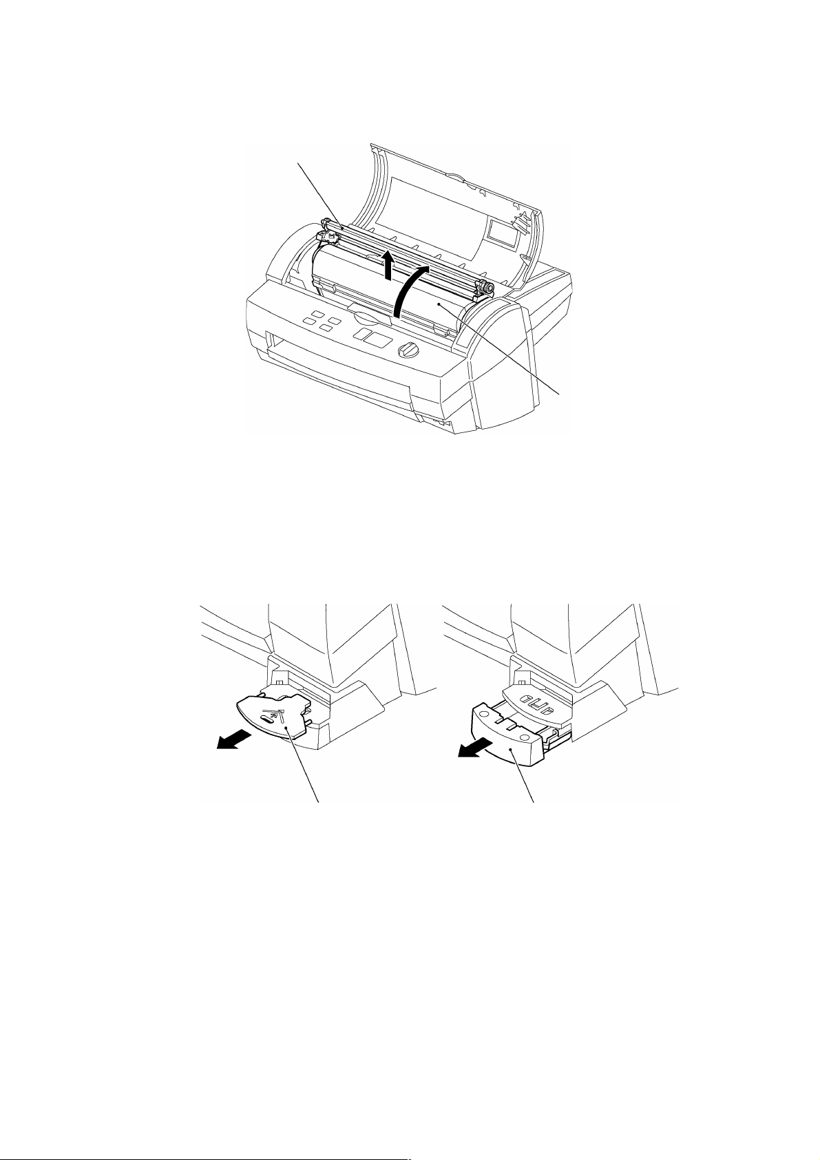
3. Lift up the Roller holder assy and pull out the Film cartridge.
F
T
Roller holder assy
3.3 Covers
ilm cartrid ge
Fig. 3.2-2 Removing the Film Cartridge 2
3.3.1 Removing the Trimmer Cover
1. Pull out the T-cutter plate and the Trimmer bottom cover.
T-cutter plate
Fig. 3.3-1 Removing the Trimmer cover 1
rimmer bottom cover
Page 25
3-3
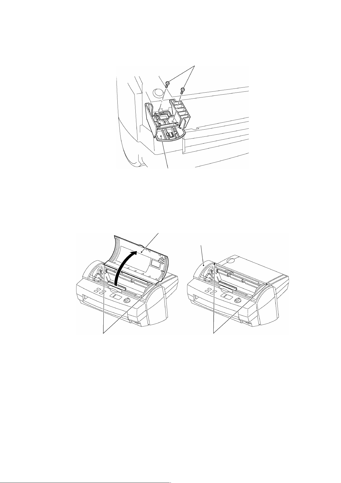
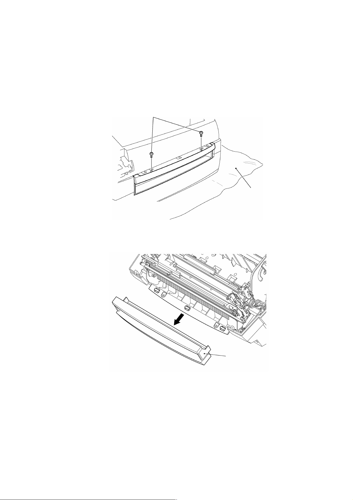
2. Remove the two Trimmer cover screws. Remove the Trimmer upper cover.
T
T
B
S
rimmer cover screws
Fig. 3.3-2 Removing the Trimmer cover 2
3.3.2 Removing the Top Cover B
Open the Top cover B. Lift the Top cover B shafts out of t he shaf t recesses in the Body
cover and remove Top cover B.
rimmer upper cover
Top co ver B
ody cover
Shafts
Fig. 3.3-3 Removing the Top Cover B
haft recesses
Page 26
3-4
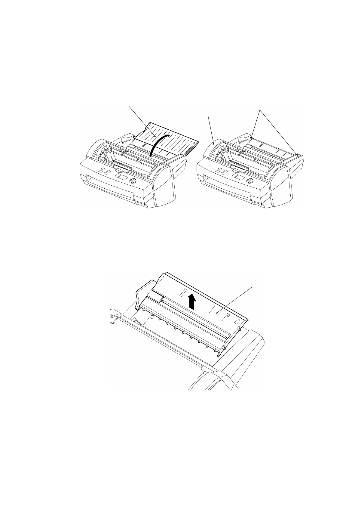
3.3.3 Removing the Sub-tray
S
1. Open the Sub-tray.
2. Flex the center of the sub-tray toward you to release the shafts from the shaft
recesses in the Body cover. Remove the sub-tray.
ub-tray
Fig. 3.3-4 Removing the Sub-tray
3.3.4 Removing Paper Tray A and Paper Guide
1. Flex the center of the top of Paper tray A in the direction of the arrow, then release
the left and right hooks. Pull Paper tray A upward to remove it.
Shaft re cesses
Body cover
Fig. 3.3-5 Removing Paper Tray A
Paper tray A
Page 27
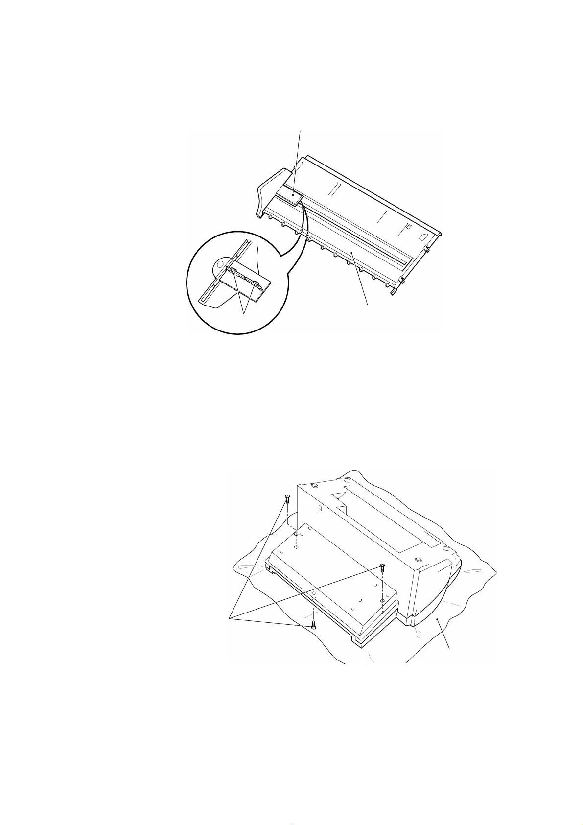
2. Disengage the Paper guide hooks (at the rear of the Paper tray) CL2000011
from Paper tray A. Remove the Paper guide.
Paper gu ide
Hooks
Fig. 3.3-6 Removing the Paper Guide
3.3.5 Removing the Body Cover
1. Remove the two Bottom cover screws B from the bottom of the Bottom cov er B.
And remove one screw from the surface of Body cover.
∗ When inverting the unit to perform this work, place it on a soft cloth to avoid
scratching the cover.
Pape r tray
Bottom cover screws B
Soft cloth
Fig. 3.3-7 Removing the Body Cover 1
3-5
Page 28
3-6
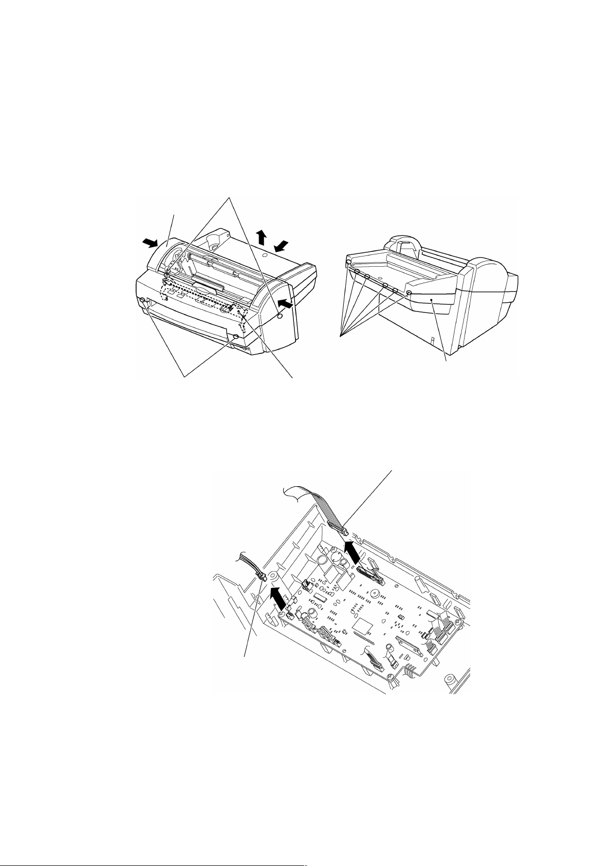
2. Lift the rear of the Bottom cover in the direction of arrow B while pushing it in t he
R
A
Y
S
C
direction of arrow A to release the six hooks on the rear face.
3. Push the sides of Body cover in the directions indicated by the arrows C to release
the hook at the left and right side.
4. Push on the Y-diversion lever assy and release the two hooks from the front of the
Body cover.
Side hook s
Body cover
B
C
ear hooks
Bottom cove r B
Front hooks
Fig. 3.3-8 Removing the Body Cover 2
-diversion lever assy
5. Disconnect the Switch harness assy and the Cover switch assy connectors from the
Main PCB and remove the Body cover.
witch harness assy
over swit ch assy
Fig. 3.3-9 Removing the Body Cover 3
Page 29
3-7
3.3.6 Removing the Front Cover
F
F
1. Remove the two Front cover screws under the Bottom cover B.
∗
When removing the Body cover, remove the two Front cover screws and the two
screws at the rear of the Bottom cover B at the same time.
∗
When inverting the unit to perform this work, place it on a soft cloth to avoid
scratching the cover.
ront cover screws
Fig. 3.3-10 Removing the Front Cover 1
Soft cloth
2. Pull the front cover forward to remove it.
(The Body cover must be removed before removing the Front cover.)
ront cover
Fig. 3.3-11 Removing the Front Cover 2
Page 30
3.3.7 Removing Paper Tray B CL2000011
1. Remove Tray B Stopper.
2. Lift the top of Paper tray B in the direction of arrow A to disengage t he lug from the
Cassette holder.
3. Slide Paper tray B in the direction of arrow B, then lift it in t he direct ion of arrow C t o
remove it.
Paper tray B
B
Lug
A
C
Fig. 3.3-12 Removi ng Paper Tray B
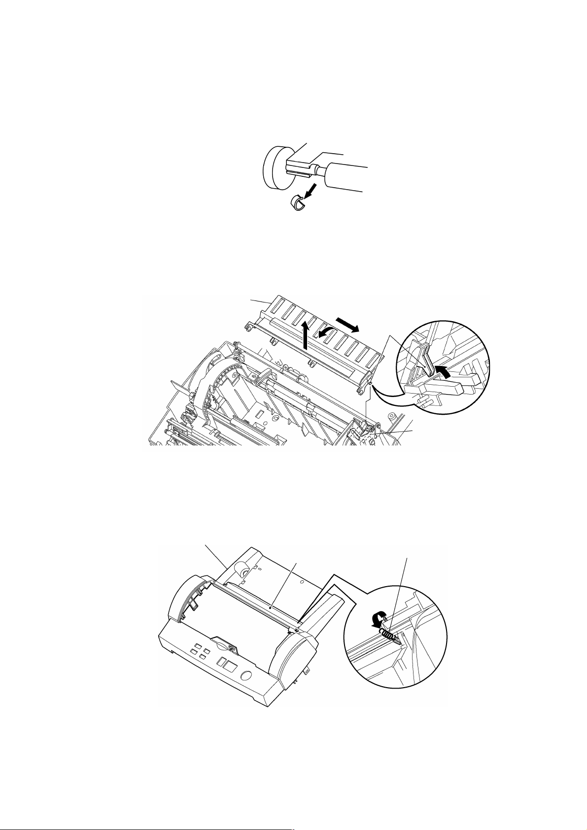
3.3.8 Removing the Back Cover
1. Remove the Back cover spring.
Body cover
Back cover
Cassette hold er
Back cover sprin g
Fig. 3.3-13 Rem ovi ng t he Back Cover 1
3-8
Page 31

3-9
2. Flex the center of the Back cover toward you to release the shafts from t he shaf t
B
S
F
C
C
recesses in the Body cover. Remove the Back cover.
During this operation, take care not to deform the film att ached t o t he Back Cover.
hafts
ack cover
ilm
Body cover
Fig. 3.3-14 Removing the Back Cover 2
3.3.9 Removing the Cover Switch
1. Remove the cover switch screw. Remove the cover switch assy.
Fig. 3.3-15 Removing the Cover Switch Assy
over switch assy
over switch screw
Page 32

3
3.3.10 Removing the Dial Switch Holder Assy B
D
D
D
1. Remove the eight Dial holder screws. Remove the Dial switch holder assy B.
2. Disconnect the Push SW assy 1 (white) and Push SW assy 2 (red) connectors from
the SW PCB.
∗
Take care not to apply force to the connectors between switch and harness in
Push switch assy 1 and 2.
ial holder screws
Push switch assy 1 and 2
ial holder screws
Fig. 3.3-16 Removing the Dial Switch Holder Assy
ial switch holder a ssy
-10
Page 33

3
3.3.11 Removing the Push Switch Assy
P
P
1. Remove the two Push switch screws. Remove the Push SW assy 1 (white) and
Push SW assy 2 (red).
∗
Before removing the Push SW assy 1 and 2, turn the Dial switch such that it
does not touch the push switches (mid-point between Push SW assy 1 and
Push SW assy 2).
∗
Take care not to apply force to the connectors between the Push switch and
harness.
ush switch scr ews
ush switch assy 1 and 2
Fig. 3.3-17 Removing the Push Switches
-11
Page 34

3
3.4 Chassis Assy
3.4.1 Removing the Harness Connectors
1. Remove 11 harness connectors from the Main PCB. Do not remove the power
harness assy (red/black CN13).
Power harne ss assy
Fig. 3.4-1 Removing the Harness Connectors 1
2. Disconnect the harnesses from the eight hooks on the Bottom cover B.
Fig. 3.4-2 Removing the Harness Connectors 2
3. Peel off the tape that holds the harnesses inside the right of Bot t om cover B, then
remove the harnesses from the Bottom cover B.
-12
Page 35

3
3.4.2 Removing the PST PCB (Paper Sensor PCB)
Remove the PST PCB (Paper sensor PCB) screws from the Main chassis B, then
remove the PST PCB (Paper sensor PCB).
PST PCB screw
PST PCB
Fig. 3.4-3 Removing the PST PCB (Paper S ensor PCB)
-13
Page 36

3
3.4.3 Removing the Chassis Assy
G
G
B
1. Remove the Ground wire screw from the Main chassis B, then disconnect the
ground wire.
Ma in chassis B
round wire
Fig. 3.4-4 Removing the Chassis Assy 1
round wire screw
2. Remove the two Bottom cover screws B and the washers from under the Bottom
cover B.
∗
When inverting the unit to perform this work, place it on a soft cloth to avoid
scratching the cover.
ottom cover B
Bottom cover screws B
Washers
Fig. 3.4-5 Removing the Chassis Assy 2
-14
Page 37

3. Open the Roller holder assy, then remove the four Bottom cover screws CL2000011
with four washers from under the Chassis assy.
Bottom Cover Screw A
Roller Holder Assy
Fig. 3.4-6 Removing the Chassis Assy 3
4. Pull out the Chassis assy from Bottom cover.
Chassis assy
Fig. 3.4-7 Removing the Chassis Assy 4
3-15
Page 38

3
3.5 PCBs
M
M
P
M
J
3.5.1 Removing the Main PCB
1. Disconnect the power harness assy (red/black) from the Main PCB.
2. Remove the four Main PCB screws. Remove the Main PCB.
ower harness assy
Fig. 3.5-1 Removing the Main PCB
3.5.2 Removing the Jack PCB Assy
Remove the Jack PCB screw and remove the Jack PCB assy.
∗
The core shown in the diagram is fitted in the EU-specification LX-300 only.
ain PCB screw
ain PCB assy
ain PCB screw
ack PCB screw
Jack PCB a ssy
Fig. 3.5-2 Removing the Jack PCB Assy
-16
Page 39

3
3.5.3 Removing the Switch PCB Assy
S
S
L
S
C
1. Remove the eight Switch PCB screws from under the Body cover. Remove the
Switch PCB assy.
witch PCB assy
Switch PCB screws
witch PCB screws
Fig. 3.5-3 Removing the Switch PCB Assy 1
2. Remove the Start key, Stop key, Two-connection switch, Continuous key, and Ext r a
border key.
The LED lenses can be removed from the Top cover by pushing them hard with a
fine object such as a pen tip.
LED lenses
ED lens
Extra border key
Two -con nection switch
ontinuous key
top ke y
Start key
Fig. 3.5-4 Removing the Switch PCB Assy 2
-17
Page 40

3
3.6 X-cutter Unit
X
X
L
X
L
3.6.1 Removing the X-cutter Unit
1. Remove the Y-cutter assy.
2. Remove the two X-cutter screws. Move the X-cutter unit toward the right to remove
it.
∗
Remove the Chassis assy from the Bottom cover when replacing the X-cutter
unit.
Y-cutter assy
-cutter screw s
Fig. 3.6-1 Removing the X-cutter Unit
3.6.2 Removing the Leaf Switch F Assy.
Remove the Leaf switch F screw, then remove the Leaf switch F assy.
∗
Take care not to bend the connector root on the Leaf switch F assy harness.
-cutter unit
Tape sensor holde r
Fig. 3.6-2 Removing the Leaf Switch F Assy
-cutter unit
eaf switch F assy
eaf switch F screw
-18
Page 41

3
3.7 Y-CA Chassis Assy and Y-cutter Arm
Y
R
Y
A
3.7.1 Removing the Y-CA Chassis Assy
1. Remove the Y extension springs.
2. While the Roller holder is locked, remove the two Y-CA chassis screws.
3. Disengage the end of the Y-cutter arm from the Y sensor carriage by moving it in
direction A. Remove the Y-CA chassis assy.
sensor carriage
-cutter a rm
Y-cutter arm
Y-CA chassis screws
oller holder
Y ex tension spring
Fig. 3.7-1 Removing the Y-CA Chassis Assy
-19
Page 42

3
3.7.2 Removing the Y-CA Motor
Y
Y
Y
Y
c
s
1. Remove the Y-CA motor screws and remove the Y-CA motor.
-CA motor
Fig. 3.7-2 Removing the Y-CA Motor
3.7.3 Removing the Y-cutter Arm
1. Remove the retaining ring from the Y-cutter arm shaft, pull out the Y-cutter arm shaft,
and remove the Y-cutter arm.
2. Remove the Y-CA arm screw, then remove the Y-CA arm.
Y-cutter arm
-CA motor screw
sensor
arriage arm
crew
Y-CA arm
-cutter a rm shaft
Retaining rings
Fig. 3.7-3 Removing the Y-cutter Arm
-20
Page 43

3
3.8 Y-sensor Rail Unit
Y
F
Y
3.8.1 Removing the Y-sensor Rail Unit
1. Remove the F cable from the Cassette holder.
2. Remove the two Y-sensor rail screws.
3. Disengage the tip of the Actuator top from the film hole, t hen remove t he Y-sensor
rail unit in the direction of the arrow.
Film
The tip of the
Actuator top
-sensor rail screw
-sensor rail unit
Fig. 3.8-1 Removing the Y-sensor Rail Unit
cable
Cassette hold er
-21
Page 44

3
3.8.2 Disassembling the Y-sensor Rail Unit
R
F
P
f
Y
1. Remove the Retaining ring from the Y-sensor shaft, then pull out the Y sensor shaft.
2. Remove the FPC holder A from the Y-sensor rail, then remove the Y-sensor
carriage.
Retaining ring
Y-sensor rail screw
FPC holder
-sensor carriage
Y-sensor shaft
aper feed
ilm
PC holder
Y-sensor rail
Y-sensor rail screw
Fig. 3.8-2 Disassembling the Y-s ensor Rail Unit
Reinforcement
film
etaining ring
-22
Page 45

3
3.9 Roller Holder Assy
R
R
3.9.1 Removing the Roller Holder Assy
1. Lift up the Roller holder unit and disconnect the Roller holder return spring.
2. Remove the four Retaining rings (two from the Roller holder, two from t he Paper
feed holder), then remove the Roller holder unit.
3. Remove the plastic spacer from the rivet pins at each end of the Roller holder assy.
Retaining rings
Spacer
Fig. 3.9-1 Removing the Roller Holder Assy
oller holder return spring
oller holder unit
Retaining rings
Spacer
-23
Page 46

3
3.10 Paper Feed Roller
I
P
P
3.10.1 Removing the Paper Feed Holder Assy
1. Remove the two Idle gears A, one Double gear B, one Double gear A, the Roller
gear AD, and the two Paper feed roller springs from the Paper feed holder L assy,
then remove the Paper feed roller unit.
aper feed roller spri ngs
Roller gear AD
Double gear B
Double gear A
Idle gear A
dle gear A
Fig. 3.10-1 Removing the Paper Feed Holder Assy
2. Rotate the Paper feed holder plates L/R backward. Remove the Paper feed holder
plates L/R by pulling the hooks out of the cut-outs in t he Chassis L/ R.
Paper feed holder plate L
aper feed holder plate R
Fig. 3.10-2 Removing the Paper Feed Holder Plates L/R
-24
Page 47

3
3. Remove the Bearing and Sub-bearing and remove the Actuator top from the Paper
B
S
S
L
L
feed roller assy.
Actuator top
Fig. 3.10-3 Removing the Actuator Top
3.11 Left Side of the Main Chassis
3.11.1 Removing the LF Motor
1. Remove the three LF motor holder screws, then remove the LF motor holder assy
and the three Spacers.
2. Remove the two LF motor screws from the LF motor holder assy, then remove the
LF motor.
ub bearing
earing
F motor screw
pacer
F motor holder screw
LF moto r
Fig. 3.11-1 Removing the LF Motor
-25
Page 48

3
3.11.2 Removing the Gears
5
G
789
3
4
6
G
1. Remove the gears according to the sequence of numbers in the diagram below.
ear holders
1
2
10
Fig. 3.11-2 Removing the Gears
2. Remove the two Gear holders simultaneously. Remove the Gear holder spring from
the Gear holders.
∗
The Gear holder spring may be stretched if the Gear holders are removed
separately.
Gear holde r
Gear holder spring
Idle gears B
ear holder
Fig. 3.11-3 Removing the Gear Holders and Gear Holder Spring
-26
Page 49

3
3.12 Right Side of the Main Chassis
S
S
I
C
L
T
L
C
T
T
T
S
T
3.12.1 Removing the Right Side of the Chassis
1. Remove the two Idle gears A.
2. Remove the two SG motor screws and remove the SG motor.
3. Remove the Leaf switch SG screw, then remove the Leaf switch SG assy.
4. Remove the T-lever shaft.
dle gears A
hassis R support
-lever shaft
eaf switch SG assy
Fig. 3.12-1 Removing the Right Side of the Chass i s 1
hassis R support screw
eaf switch SG assy screw
G motor
G motor screws
5. Push down on the T-lever unit to align the slot hole with the shaft, then remove the
unit.
-lever A
lot
T-lever unit
-lever spring
-lever B
cam roller
Fig. 3.12-2 Removing the T-lever Unit
-27
Page 50

3
6. Remove the Control cam gear and Double gear S.
D
ouble gear S
Control cam gea r
Fig. 3.12-3 Removing the Right Side of the Chass i s 2
7. Remove the screws, then remove the Chassis R support. (See Fig. 3.12-1.)
3.12.2 Removing the YC Lift Shaft and LF Change Shaft
1. Remove the Paper eject roller springs.
2. Remove the Y extension spring.
3. Remove the Retaining ring for the YC lift shaft at t he lef t side of the Main chassis.
Retaining ring
Paper eject roller springs
Y ex tension springs
Fig. 3.12-4 Removing the YC Lift Shaft and LF Change Shaf t 1
-28
Page 51

3
4. Move the YC lift shaft sever al m illim eters toward the right side of the Main c hass is
and remove the YC Lift arm.
LF lift arm
YC lift shaft
YC lift arm
Fig. 3.12-5 Removing the YC Lift Shaft and LF Change Shaf t 2
5. Remove the left end of the YC lift shaft f r om the Chassis L. Remove the YC lift shaft
by pulling the right end of the YC lift shaft through the hole in Chassis R toward the
middle of the chassis.
6. Move the LF change shaft several millimeters t owar d t he M ain chassis R. Remove
the LF change shaft by pulling the right end of the shaft t hr ough t he hole in Chassis
R toward the middle of the chassis.
∗
When pulling the right end of the YC lift shaft and LF change shaft t h rough the
hole in Chassis R, tilt the shafts so that they can be pulled smoothly. Never pull
them through the hole forcibly.
-29
Page 52

3
3.13 Paper Eject Roller
P
P
H
3.13.1 Removing the Paper Eject Roller Unit
1. Push down the Paper eject shaft holder until they becomes free.
2. Push the Paper eject roller toward the left and remove it from the right end.
3. Remove the Paper eject sub-roller in exactly the same manner as the Paper eject
roller: move it toward the left then remove it from t he right end.
aper eject roller
Paper eject sub roller
Fig. 3.13-1 Removing the Paper Eject Roller Unit 1
aper eject shaft holder
4. Remove the Paper eject roller bearing hook, then remove the Paper eject roller
bearing.
Paper eject roller bearings
ooks
Fig. 3.13-2 Removing the Paper Eject Roller Unit 2
-30
Page 53

3
3.14 Y-diversion Lever
Y
3.14.1 Removing the Y-diversion Lever Assy
1. Lift the Y-diversion lever assy to remove it.
Fig. 3.14-1 Removing the Y-diversion Lever
-diversion lever assy
-31
Page 54

3
3.15 Trimming Mechanism
L
B
R
R
D
R
3.15.1 Disassembling the Trimming Mechanism
1. Remove the Leaf switch TRI screw, then remove the Leaf switch assy TRI .
2. Remove the T-cutter screw, then remove the T-cutter assy.
Leaf switch TRI screw
T-cutter screw
T-cutter unit
Fig. 3.15-1 Disassembling the Trimming Mec hanism
3.16 Driving Roller
3.16.1 Removing the Driving Roller
1. Remove the Roller gear CD.
2. Remove the Retaining ring, push the Driving roller assy toward the left then remove
it from the right end.
3. Remove the Bearings R/L.
eaf switch TRI assy
Bearing L
etaining ring
riving roller assy
etaining ring
earing R
oller ge ar CD
Fig. 3.16-1 Removing the Driving Roller
-32
Page 55

3
3.17 Main Chassis B
E
C
H
E
E
T
3.17.1 Removing the Main Chassis B
1. Disengage the harness from the hooks under the Cassette holder and the Edging
saddle at the rear of the main chassis B.
2. Remove the Edging saddle from the rear of the main chassis B.
3. Remove the tape holding the ENC sensor harness.
4. Remove the Leaf switch C3/C4 screws, then remove the Leaf switch C3/C4
assemblies.
5. Remove the two Cassette actuators.
assette holder
dging saddle
Leaf switch C3 assy
Leaf switch C3 scr ew
Cassette actuator
Leaf switch C4 scr ew
Leaf switch
C4 assy
he bottom face of cassette holder
Fig. 3.17-1 Removing the Main Chassis B
NC senso r
NC sensor harness
Tape
arness
Rear of the main chassis B
-33
Page 56

3
3.17.2 Removing the Cassette Holder
H
E
E
1. Push in the three hooks on the front face that fix the Casset t e holder.
2. Pull out the Cassette holder in the direction of the arrow.
Fig. 3.17-2 Removing the Cassette Holder
3.17.3 Removing the ENC Sensor PCB
ooks
Remove the ENC sensor PCB screw, then remove the ENC sensor assy.
NC sensor assy
NC sensor PCB screw
Fig. 3.17-3 Removing the ENC Sensor PCB
-34
Page 57

3
3.17.4 Removing the Main Chassis L, R, and F
M
M
Remove the ten Side chassis screws (five each side), then remove the Main chassis L,
R, and F.
Side chassis screws
Ma in chassis F
ain chassis L
ain chassis B
Ma in chassis R
Side chassis screws
Fig. 3.17-4 Removing the Main Chassis L, R, and F
-35
Page 58

Chapter 4.
ASSEMBLY PROCEDURES
Page 59

CONTENTS
Chapter 4. ASSEMBLY PROCEDURES
4.1 Safety Precautions............................................................................................................4-1
4.2 Table of Tightening Torques............................................................................................. 4-2
4.3 Main Chassis B .................................................................................................................4-3
4.3.1 Installing the Main Chassis L, R, and F................................................................ 4-3
4.3.2 Installing the ENC Sensor PCB............................................................................4-3
4.3.3 Installing the Cassette Holder...............................................................................4-4
4.3.4 Installing the Main Chassis B ...............................................................................4-5
4.4 Driving Roller.....................................................................................................................4-6
4.4.1 Installing the Driving Roller...................................................................................4-6
4.5 Trimming Mechanism........................................................................................................4-7
4.5.1 Assembling the Trimming Assy............................................................................4-7
4.6 Paper Eject Roller and Y-diversion Lever.........................................................................4-8
4.6.1 Installing the Paper Eject Roller Unit and Y-diversion Lever...............................4-8
4.6.2 Installing the Paper Eject Roller ...........................................................................4-9
4.7 Right Side of the Main Chassis.......................................................................................4-10
4.7.1 Installing the YC Lift Shaft and LF Change Shaft...............................................4-10
4.7.2 Installing the Right Side of the Chassis..............................................................4-11
4.8 Left Side of the Chassis.................................................................................................. 4-14
4.8.1 Installing the Gears............................................................................................. 4-14
4.8.2 Installing the LF Motor ........................................................................................4-15
4.9 Paper Feed Roller...........................................................................................................4-16
4.9.1 Installing the Paper Feed Holder Assy and the Paper Feed Roller Assy..........4-16
4.10 Roller Holder Assy ..........................................................................................................4-19
4.10.1 Installing the Roller Holder Assy ........................................................................4-19
4.11 Y-sensor Rail Unit ...........................................................................................................4-20
4.11.1 Assembling the Y-sensor Rail Unit (Attaching Y-sensor PCB Assy).................4-20
4.11.2 Installing the Y-sensor Rail Unit .........................................................................4-22
4.12 Y-CA Chassis Assy and Y-Cutter Arm............................................................................4-23
4.12.1 Installing the Y-cutter Arm ..................................................................................4-23
4.12.2 Installing the Y-CA Motor....................................................................................4-24
4.12.3 Installing the Y-CA Chassis Assy.......................................................................4-24
4.13 X-cutter U nit ....................................................................................................................4-26
4.13.1 Installing the Leaf Switch F Assy........................................................................4-26
4.13.2 Installing the X-cutter Unit...................................................................................4-26
4.14 Harnesses .......................................................................................................................4-27
4.14.1 Installing the Harnesses .....................................................................................4-27
i
Page 60

ii
4.15 PCBs ...............................................................................................................................4-28
4.15.1 Installing the Jack PCB Assy..............................................................................4-28
4.15.2 Installing Main PCB Assy 1 ................................................................................4-28
4.16 Chassis Assy ...................................................................................................................4-29
4.16.1 Installing the Chassis Assy.................................................................................4-29
4.16.2 Installing the PST PCB Assy..............................................................................4-30
4.16.3 Installing the Harness Connectors .....................................................................4-31
4.17 Covers .............................................................................................................................4-32
4.17.1 Installing the Push SW Assy...............................................................................4-32
4.17.2 Installing the Dial Switch Holder Assy................................................................4-33
4.17.3 Installing the Cover Switch................................................................................. 4-35
4.17.4 Installing the Back Cover....................................................................................4-35
4.17.5 Installing Paper Tray B ....................................................................................... 4-36
4.17.6 Installing the Front Cover....................................................................................4-36
4.17.7 Installing the Body Cover....................................................................................4-37
4.17.8 Installing the Paper Tray A and Paper Guide.....................................................4-39
4.17.9 Installing the Sub-tray.........................................................................................4-40
4.17.10 Installing the Top Cover B.................................................................................. 4-41
4.17.11 Installing the Trimmer Upper Cover ...................................................................4-41
4.18 Installing the Y-cutter ......................................................................................................4-42
4.19 Installing the Film Cartridge ............................................................................................4-43
4.19.1 Installing the A3 Cartridge.................................................................................. 4-43
4.19.2 Installing the A4/A6 Cassette Attachment..........................................................4-44
Page 61

4-1
4.1 Safety Precautions
•
When conducting reassembly operations, place the unit on a grounded anti-static
sheet. LSI and other electronic components are sensitive to static electricity and
may be damaged if touched while charged.
•
Before transporting a circuit board, wrap it in a conducting sheet such as aluminum
foil.
•
When using a soldering iron or other heat-producing tool, ensure that heat does not
damage wires, circuit boards, or plastic parts such as covers.
•
Take care not to lose small screws or washers installed when replacing parts.
•
Tighten all screws to the torque specified in the table below.
•
As a safety precaution, wear gloves when conducting assembly operations.
Page 62

4-2
4.2 Table of Tightening Torques
Name of screw Qty. Screw size Tightening torque See page
Side chassis screw 10 TAPTITE, CUP M3 × 5 0.49 to 0.686 N•m (5 to 7 kgf•cm)
Reinforcing plate for frame R screw 2 TAPTITE, CUP M3 × 5 0.49 to 0.686 N•m (5 to 7 kgf•cm)
ENC PCB screw 1 TAPTITE, BIND B M3 × 8 0.49 to 0.686 N•m (5 to 7 kgf•cm)
Leaf switch C3 screw 1 SCREW, PAN M2.6 × 10 0.196 to 0.392 N•m (2 to 4 kgf•cm)
Leaf switch C4 screw 1 SCREW, PAN M2.6 × 10 0.196 to 0.392 N•m (2 to 4 kgf•cm)
Leaf switch TRI screw 1 TAPTITE, PAN B M2 × 6 0.196 to 0.392 N•m (2 to 4 kgf•cm)
Leaf switch F screw 1 TAPTITE, PA N B M 2 × 6 0.196 to 0.392 N•m (2 to 4 kgf•cm)
Sensor holder screw 1 TAPTITE, CUP S M2.6 × 6 0.49 to 0.686 N•m (5 to 7 kgf•cm)
X-cutter screw 2 SCREW, BIND M3 × 6 0.49 to 0.686 N•m (5 to 7 kgf•cm)
Detent plate screw 1 TAPTITE, BIND B M3 × 8 0.49 to 0.686 N•m (5 to 7 kgf•cm)
Plate spring 3 screw 1 TAPTITE,CUP M3 × 5 0.49 to 0.686 N•m (5 to 7 kgf•cm)
Leaf switch SG sc rew 1 SCREW, PAN M2.6 × 10 0.196 to 0.392 N•m (2 to 4 kgf•cm)
SG motor screw 2 TAPTITE, CUP M3 × 5 0.49 to 0.686 N•m (5 to 7 kgf•cm)
LF motor screw 2 TAPTITE, CUP M3 × 5 0.49 to 0.686 N•m (5 to 7 kgf•cm)
LF motor holder screw 3 TAPTITE, CUP M 3 × 20 0.49 to 0.686 N•m (5 to 7 kgf•cm)
Y-CA sensor PCB screw 1 TAPTITE, PAN B M2 × 8 0.196 to 0.392 N•m (2 to 4 kgf•cm)
Y-sensor rail screw 2 TAPTITE,CUP M3 × 5 0.49 to 0.686 N•m (5 to 7 kgf•cm)
Y-sensor carriage arm screw 1 SCREW, B IND B TITE
M3 × 10
Y-CA motor screw 1 SCREW, F LANGED M2.6 × 5 0.196 to 0.392 N•m (2 to 4 kgf•cm)
Sensor holder screw 1 TAPTITE, CUP M3 × 5 0.49 to 0.686 N•m (5 to 7 kgf•cm)
Y-CA chassis screw 2 TAPTITE, CUP M3 × 5 0.49 to 0.686 N•m (5 to 7 kgf•cm)
Switch PCB screw 8 TAPTITE, BIND B M3 × 12 0.49 to 0.686 N•m (5 to 7 kgf•cm)
Jack PCB screw 1 TAPTITE, BIND B M3 × 8 0.49 to 0.686 N•m (5 to 7 kgf•cm)
Main PCB screw 4 TAPTITE, BIND B M3 × 8 0.49 to 0.686 N•m (5 to 7 kgf•cm)
Bottom cover screw A 4 TAPTITE, CUP B M4 × 12 0.98 to 1. 176 N•m (10 to 12 kgf•cm)
Bottom cover screw B 2 SCREW, BIND M3 × 6 0.49 to 0.686 N•m (5 to 7 kgf•cm)
Ground wire screw 1 SCREW, CUP M3 × 5 0.49 to 0.686 N•m (5 to 7 kgf•cm)
PST PCB screw 1 SCREW, BIND M3 × 6 0.49 to 0.686 N•m (5 to 7 kgf•cm)
Push switch 1 screw 1 SCREW, PAN M1.7 × 6 0.075 to 0.125 N•m
Push switch 2 screw 1 SCREW, PAN M1.7 × 6 0.075 to 0.125 N•m
Dial holder screw 8 TAPTITE, BIND B M3 × 8 0.49 to 0.686 N•m (5 to 7 kgf•cm)
Plate spring screw 1 SCREW, FLANGED M2.6 × 5 0.196 to 0.392 N•m (2 to 4 kgf•cm)
Plate spring 2 screw 1 SCREW, FLA NGED M2.6 × 5 0.196 to 0.392 N•m (2 to 4 kgf•cm)
Adjustment plate screw 1 TAPTITE, BIND B M3 × 8 0.49 to 0.686 N•m (5 to 7 kgf•cm)
Cover switch screw 1 TAPTITE, PAN B M2.6 × 12 0.196 to 0.392 N•m (2 to 4 kgf•cm)
Front cover screw 2 TAPTITE, BIND B M2.6 × 8 0.25 to 0.35 N•m
Bottom cover screw A 3 TAPTITE, BIND B M3 × 8 0.49 to 0.686 N•m (5 to 7 kgf•cm)
Trimmer bottom cover 2 SCREW, BIND M3 × 5 0.49 to 0.686 N•m (5 to 7 kgf•cm)
T-cutter screw 1 TAPTITE, CUP M3 × 5 0.49 to 0.686 N•m (5 to 7 kgf•cm)
Chassis R support sc rew 1 TAPTITE, CUP M3 × 5 0.49 to 0.686 N•m (5 to 7 kgf•cm)
0.49 to 0.686 N•m (5 to 7 kgf•cm)
(0.77 to 1.26 kgf•cm)
(0.77 to 1.26 kgf•cm)
(2.55 to 3.57 kgf•cm)
Page 63

4-3
4.3 Main Chassis B
M
E
B
E
E
P
4.3.1 Installing the Main Chassis L, R, and F
1. Insert the lugs on the Main chassis B and F into the square holes in the Main
chassis L and R. Assemble the Main chassis L, R, F, and B with the ten Side
chassis screws (five each side).
2. Attach the Edging saddle to the Main chassis B.
Side chassis screws
Ma in chassis R
Ma in chassis F
ain chassis B
dging saddle
Ma in chassis L
Side chassis screws
Fig. 4.3-1 Installing the Main Chass i s L, R, and F
4.3.2 Installing the ENC Sensor PCB
Align the boss on the ENC sensor PCB assy. Attach the ENC sensor PCB assy to the
Cassette holder with the ENC sensor PCB screw.
Pass the ENC sensor harness through the hole in the Cassette holder.
oss
NC Sensor PCB assy
NC Sensor
CB screw
Fig. 4.3-2 Installing the ENC Sens or P CB
Page 64

4-4
4.3.3 Installing the Cassette Holder
H
E
M
H
1. Pass the ENC sensor PCB harness through the hole in the bottom of Main chassis
B.
2. Insert the lugs at the front of the Casset t e holder and click t he hooks at t he rear ont o
Main chassis B.
Lugs
Fig. 4.3-3 Installing the Casset te Holder
ooks
NC sensor PCB assy
ain chassis B
arness
(Chassis R, L and F are omitted for explanation.)
Page 65

4-5
4.3.4 Installing the Main Chassis B
C
E
E
H
C
a
H
T
C
1. Install the two Cassette actuators.
2. Install the Leaf switch C3 (red) and C4 (yellow) assemblies using the Leaf switch
C3/C4 screws.
∗
Take care not to deform the tip of the leaf switch.
3. Engage the Leaf switch C3 and C4 harness into the hook under the Cassette holder,
then pass it through the Edging saddle under the Chassis B.
assette holder
Leaf switch
C3 assy
assette
ctuator
Leaf switch C4 scr ews
Leaf switch
C3/C4 a ssy
he bottom face of
assette holder
Fig. 4.3-4 Installing the Main Chass i s B
NC senso r
NC sensor harness
arness
Tape
ook
4. Tape the ENC sensor PCB harness inside the marked line (the side of the Cassette
holder hooks) under the Chassis B, then return the harness to the Edging saddle
under the Chassis B.
Page 66

4-6
4.4 Driving Roller
R
D
B
B
4.4.1 Installing the Driving Roller
1. Attach the Retaining ring to the right end of the Driving roller assy (wit h t he short er
metal part).
2. Insert the Bearings L/R into the Driving roller. Mount it sequent ially into Main
chassis L and Main chassis R.
3. After installing Bearings L/R into the Main chassis L/R, at t ach t he Retaining ring to
the left end of the Driving roller assy.
4. Install the Roller gear CD.
earing L
riving roller assy
etaining ring
earing R
Retaining ring
Roller gear CD
Fig. 4.4-1 Installing the Driving Rol l er
Page 67

4-7
4.5 Trimming Mechanism
L
L
T
4.5.1 Assembling the Trimming Assy
1. Align the Leaf switch assy TRI with the T-cutter assy boss hole and attach it with the
Leaf switch TRI screw.
2. Fasten the harness to the hooks.
Engage the harness into the hook under the Cassette holder, then fix it wit h t ape on
the two marked areas (Chassis B front face and Chassis R inside surface).
3. Align the T-cutter assy with the boss holes and install it with the T-cut t e r screw.
eaf switch TRI assy
eaf switch TRI screw
T-cutter screw
Leaf switch TRI harness
-cutter a ssy
The botto m face of
cassette holder
Fig. 4.5-1 Assembling the Trimming Assy
Page 68

4-8
4.6 Paper Eject Roller and Y-diversion Lever
Y
4.6.1 Installing the Paper Eject Roller Unit and Y-diversion Lever
1. Temporarily position the Y-diversion Lever assy on the Main chassis F.
-diversion lever assy
Fig. 4.6-1 Installing the Y-diversion Lever 1
2. Install the Paper eject roller bearings such that the Y-diversion lever arms are
sandwiched between the Paper eject roller bearing and the Main chassis L/R.
Fasten the Paper eject roller bearings with the Hooks (both L/R).
Paper eject roller bearings
Hook
Fig. 4.6-2 Installing the Y-diversion Lever 2
Page 69

4-9
4.6.2 Installing the Paper Eject Roller
P
P
P
G
P
1. With both ends of the Paper eject roller inserted in the Paper eject shaft holders,
move the Paper eject roller first to the left, then to the right, to insert it into the Paper
eject roller bearings. (Insert them to the end of the rubber, ensuring that t he Paper
eject roller shaft holders are correctly oriented vertically.)
2. After inserting the Paper eject roller into the bearings, move the Paper eject roller
shaft holders outward to engage with the groove in the Paper eject roller.
3. Move the paper eject sub-roller to the left, then to the right, to insert it into the Paper
eject shaft holders and the Paper eject roller bearings.
Paper eject roller
Paper eject sub roller
Fig. 4.6-3 Installing the Paper Ejec t Roller 1
aper eject roller bearings
aper eject shaft holder
4. Align the grooves in the Paper eject roller and Paper eject sub-roller shafts at the
Paper eject shaft holders and push up the Paper eject shaft holders to lock them
(both sides).
rooves
aper eject roller
Paper eject roller shaft holder
aper eject sub roller
Fig. 4.6-4 Installing the Paper Ejec t Roller 2
Page 70

4
4.7 Right Side of the Main Chassis
Y
L
B
Y
G
M
P
Y
4.7.1 Installing the YC Lift Shaft and LF Change Shaft
1. Move the LF change shaft first to the right, then to the left, to install it into the Main
chassis L and R.
2. Insert the right end of the YC Lift Shaft int o the Main chassis R, then attach the YC
lift arm to it.
3. With the boss of the YC lift arm inserted into the groove at t he right end of t he YC lift
shaft, insert the left end of the YC lift shaft into the Main chassis L and attach the
retaining ring outside Chassis L.
Retaining ring
ain Chassis L side
F change shaft
YC lift shaft
C lift shaft
roove
C lift arm
oss
Fig. 4.7-1 Installing the YC Lift S haft and LF Change Shaft 1
4. Attach the Y extension springs between the hooks inside the Main chassis L/R and
the Y-diversion lever.
5. Attach the Paper eject roller springs between the Paper eject shaft holder hooks and
the Main chassis L/R.
Paper eject roller shaft holder
-diversion lever
Y ex tension spring
ain chassis R
aper eject roller spring
Fig. 4.7-2 Installing the YC Lift S haft and LF Change Shaft 2
-10
Page 71

4
4.7.2 Installing the Right Side of the Chassis
C
L
B
B
1. Install the Double gear S.
2. Position the YC lift shaft as shown in the diagram.
3. Install the Control cam gear with the triangular mark on the Control cam gear
aligned with the triangular hole in the Chassis.
∗
Ensure that the boss at the right end of the LF change shaft and YC lif t arm is
inserted correctly into the grooves in the Control cam gear. The bosses are
correctly inserted if the Control cam gear rotates smoothly when the Y-diversion
lever is pressed.
oss
F change shaft
Double gear S
Triangular hole in the Chassis
oss
YC lift arm
ontrol cam gear
The triangular mark on the Control cam gear
Fig. 4.7-3 Installing the Right Si de of the Chassis 1
4. Install the T-lever A to the Main chassis R.
Ma in chassis R
T-cutter assy
Fig. 4.7-4 Installing the Right Si de of the Chassis 2
T-lever A
-11
Page 72

4
5. Install the T-lever B, T-cam roller, and T-cam spring onto T-lever A.
T
T
T
T
T
G
T
-cam spring
-cam roller
-lever A
-lever B
Fig. 4.7-5 Installing the Right Si de of the Chassis 3
6. Insert the T-lever shaft into the shaft holes in the Main chassis R and T-lever A/B.
Push in the T-lever shaft until the groove in the shaft engages with t he hook on t he
T-cutter assy.
T-lever B
T-cutter assy
-lever shaft
-lever A
roove
Fig. 4.7-6 Installing the Right Si de of the Chassis 4
-12
Page 73

4
7. Align the Leaf switch SG assy with the boss hole and fasten it wit h the Leaf switch
S
C
C
L
SG screw.
Before installing the Leaf switch SG assy, turn the Cont rol cam gear t o a posit ion
where it cannot interfere with the Leaf switch.
8. Install the SG motor with the two SG motor A screws.
9. Install the Idle gears A.
10. Attach the Chassis R support with the Chassis R support screw.
G motor
SG motor screws A
Leaf switch SG assy
Fig. 4.7-7 Installing the Right Si de of the Chassis 5
eaf switch SG assy screw
Idle gears A
hassis R support
hassis R support screw
-13
Page 74

4
4.8 Left Side of the Chassis
G
G
7
G
9
3
1
2
468
4.8.1 Installing the Gears
1. Mount the two Gear holders to the Main chassis L, then attach the G ear holder
springs.
ear holders
ear holder spring
Fig. 4.8-1 Installing the Gears 1
2. Install the gears according to the sequence shown in the diagram below.
Push the shaft into a gear or holder with a hook until the hook engages.
5
ear holders
10
1 (× 4)
1
Fig. 4.8-2 Installing the Gears 2
-14
Page 75

4
4.8.2 Installing the LF Motor
L
M
S
L
1. Attach the LF motor to the LF motor holder using the LF motor screws.
2. Insert the LF motor holder screws into the LF motor holder assy. Put the Spacers
over the three protruding screws. Mount the LF motor holder assy to the Main
chassis L.
∗
Fix the LF motor holder to the positioning pins, then fasten it firmly and correctly
in place with the screws.
LF moto r screw
F motor
ain chassis L
LF motor holder screw
F motor holder
Fig. 4.8-3 Installing the LF Motor
pacer
-15
Page 76

4
4.9 Paper Feed Roller
P
4.9.1 Installing the Paper Feed Holder Assy and the Paper Feed Roller Assy
1. Attach the Paper feed holder plates L (with shaft) and R to the Main chassis L and R.
∗
Assemble with the hooks on the Paper feed holder plates L/R engaged in the
cut-outs in the Chassis L/R.
Paper feed holder plate L
aper feed holder plate R
Fig. 4.9-1 Installing the Paper Feed Holder Assy
-16
Page 77

4
2. Install the Actuator top in the Paper feed holder assy.
S
P
P
P
S
C
3. Install the Bearing and Sub-bearing onto the Paper feed roller and Paper feed subroller. Insert the rollers through the slots in the Paper feed holder plates L and R.
∗
Ensure that the Actuator top fits into Part A of t he Casset t e holder.
Bearing
ub bearing
aper feed roller assy
aper feed sub roller
per feed holder plate L
Slot
Actuator top
Fig. 4.9-2 Installing the Paper Feed Roller Assy 1
Actuator top
Sub bearing
Bearing
lot
Paper feed holder plate R
assette Holder
art A
-17
Page 78

4
4. Attach the Paper feed roller springs to the left and right Sub bearing hooks and the
P
S
P
s
R
Paper feed holder plates L and R.
ub bearing
aper feed holder plate R
aper feed roller
pring
Fig. 4.9-3 Installing the Paper Feed Roller Assy 2
5. Attach the two Idle gears A, one Double gear B, one Double gear A, and the Roller
gear AD to the Paper feed holder plate L.
Double gear A
Idle gear A
Idle gear A
oller ge ar AD
Double gear B
Fig. 4.9-4 Installing the Paper Feed Roller Assy 3
-18
Page 79

4
4.10 Roller Holder Assy
R
M
R
h
r
R
4.10.1 Installing the Roller Holder Assy
1. Install the pivots for Roller holder rotation onto the Main chassis shaft s.
2. Mount the plastic spacers to the lugs (rivet pins) at each end of the Roller holder
assy.
3. Pass the lugs (rivet pins) on the roller holder unit through the curved slots on the
Main chassis L and R and the slots on top of the Paper feed roller plate.
4. Fasten the Roller holder in position with the four Retaining rings.
5. Install the Roller holder return spring while the Roller holder unit is open.
Spacer
Retaining rings
ain chassis shafts
oller
older
eturn spring
etaining ring
Fig. 4.10-1 Installing the Roller Holder Assy
oller holder assy
Spacer
Retaining ring
-19
Page 80

4
4.11 Y-sensor Rail Unit
A
F
A
2
4.11.1 Assembling the Y-sensor Rail Unit (Attaching Y-sensor PCB Assy)
1. Bend the sensor flat cable to the dimensions shown in the diagram below.
pprox. 350mm
Fig. 4.11-1 Bending the Sensor Flat Cable to the Dimensi ons
2. Attach the FPC holders A to the flat cable.
3. Locate the sensor flat cable inside the Y-sensor rail unit.
FPC holder A
Approx.
170 mm
Fig. 4.11-2 Sensor Flat Cable Location
PC holder A
pprox.
5 mm
-20
Page 81

4
4. Stick the Film and Reinforcement film to the Y-sensor rail unit.
F
R
F
Y
S
Y
R
S
5. Install the FPC holders A in the Slots in the Y sensor rail unit.
6. Pass the Y-sensor shaft through the Y-sensor rail and Y-sensor carriage and fasten
with a Retaining ring at each end.
7. Check that the sensor cable is not tight when the Y-sensor carriage is moved to the
left end, as shown in the diagram below.
Retaining ring
ilm
Y sensor shaft
-CA sensor carriage
FPC
holder A
lot
sensor rail
Fig. 4.11-3 Assembling the Y-sensor Rail Unit
einforcement film
PC holder A
lot
etaining ring
-21
Page 82

4
4.11.2 Installing the Y-sensor Rail Unit
Y
Y
F
P
1. Locate the groove on the Y-sensor shaft into the Paper feed holder plate and fast en
with the two Y-sensor rail screws.
∗
Ensure that film is inserted between the Paper feed roller and Paper feed subroller during installation.
∗
Pass the part of the Paper feed film with the Reinforcement f ilm at t ached
between the Paper feed roller and Paper feed sub-roller, then pass the end of
the Actuator top through the hole in the Paper feed film.
sensor rail scr ew
Paper feed sub roller
sensor rail unit
ilm
Paper feed roller
The end of the Actuator top
Fig. 4.11-4 Assembling the Y-sensor Rail Unit
aper feed film
-22
Page 83

4
4.12 Y-CA Chassis Assy and Y-Cutter Arm
Y
Y
R
4.12.1 Installing the Y-cutter Arm
1. Mount the Y-sensor carriage arm to the Y-cutter arm with the Y-CA arm screw.
Y-CA arm screw
Y-cutter arm
sensor carriage arm
Fig. 4.12-1 Installing the Y-cutter Arm 1
2. Pass the Y-cutter arm shaft through the Y-CA chassis assy and Y-cutter arm and
fasten with a Retaining ring at each end.
-cutter a rm
Y-CA chassis assy
Y-cutter arm shaft
etaining rings
Fig. 4.12-2 Installing the Y-cutter Arm 2
-23
Page 84

4
4.12.2 Installing the Y-CA Motor
Y
Y
1. Mount the Y-CA motor to the Y-CA chassis assy with the Y-CA motor screws.
Y-CA chassis assy
-CA motor
Y-CA moto r screw
Fig. 4.12-3 Installing the Y-CA Motor
4.12.3 Installing the Y-CA Chassis Assy
1. Insert the end of the Y-cutter arm into the Y sensor carriage.
Y sensor carriage arm
Fig. 4.12-4 Installing the Y-CA Chassis Assy 1
sensor carriage
-24
Page 85

4
2. Insert the lugs on the Y-cutter guide L into the slots (Part A) on the Y-cut t er arm.
Y
P
Y
Y
Y
3. Insert the Y-CA timing belt into the groove in the Y-cutter arm.
4. Install the Y-CA chassis assy with the two Y-CA chassis screws.
∗
Set the left and right Embosses into the holes in the Y-CA chassis before
tightening the screws.
5. Attach the Y extension spring to the Y-diversion lever and the Y-CA chassis assy.
art A
-cutter guide L
Y-cutter arm
-CA sensor carriage
Y-CA timing belt
Y-cutter arm
-CA chassis assy
Y-CA chassis screws
Fig. 4.12-5 Installing the Y-CA Chassis Assy 2
extension spring
-25
Page 86

4
4.13 X-cutter Unit
T
X
S
L
X
X
4.13.1 Installing the Leaf Switch F Assy
1. Attach the Leaf switch F assy to the Tape sensor holder with the Leaf switch F
screw.
Sensor holder
-cutter unit
ensor holder screw
Leaf switch F screw
Fig. 4.13-1 Installing the Leaf Switch F Assy
4.13.2 Installing the X-cutter Unit
Slide the X-cutter unit into position from the right side of the main unit and fasten it in
position with the two X-cutter screws.
ape sensor lever
eaf switch F assy
-cutter screw s
-cutter unit
Fig. 4.13-2 Installing the X-cutter Unit
-26
Page 87

4
4.14 Harnesses
H
E
4.14.1 Installing the Harnesses
Attach the following harnesses to the Main chassis B Edging saddle.
•
SG motor harness (black)
•
ENC harness assy (white)
•
Leaf switch TRI harnesses (black) x 2
•
Leaf switch C3 (red)/C4 (yellow) harness
dging saddle
arnesses
Fig. 4.14-1 Installing the Harnesses
-27
Page 88

4
4.15 PCBs
J
J
M
M
P
M
4.15.1 Installing the Jack PCB Assy
Install the Jack PCB assy with the Jack PCB screw.
∗
The Core shown in the diagram is applicable to EU-specification units only (LX-300).
ack PCB screw
Fig. 4.15-1 Installing the Jack PCB Assy
4.15.2 Installing Main PCB Assy 1
1. Install the Main PCB assy 1 to the Bottom cover with the four Main PCB screws.
∗
On a newly supplied part, cut away the PST SENSOR PCB assy.
2. Attach the Jack PCB Power harness assy (red/black) to the Main PCB assy 1.
Power harne ss assy
ain PCB screw s
ack PCB assy
ain PCB screw s
ain PCB assy
ST SENSOR PCB assy
Fig. 4.15-2 Installing Main PCB Assy 1
-28
Page 89

4.16 Chassis Assy CL2000011
4.16.1 Installing the Chassis Assy
1. Locate the Chassis assy aligned with the two bosses on the Bot t om cov er B.
Fasten it with the four Bottom cover screws A with four washers.
Bottom cover screws A
Fig. 4.16-1 Installing the Chassis Assy 1
2. Install the Chassis assy under the Bottom cover B using t he t w o Bot tom cover
screws B and Spring washers.
Bottom cove r B
Bottom cove r
screws B
Soft cloth
Fig. 4.16-2 Installing the Chassis Assy 2
4-29
Page 90

4
3. Attach the Ground wire to the Main chassis B using the Ground wire screw.
M
G
M
round wire screw
ain chassis B
Ground wire
Fig. 4.16-3 Installing the Chassis Assy 3
∗
The Chassis perpendicularity must be adjusted after the Chassis assy is
installed to the Bottom cover. See Section 6. Maintenance.
4.16.2 Installing the PST SENSOR PCB Assy
Attach the PST SENSOR PCB assy to the Main chassis B with the PST SENSOR PCB
screws.
PST SENSOR PCB screw
PST SENSOR PCB assy
ain chassis B
Fig. 4.16-4 Installing the PST SENSOR PCB Assy
-30
Page 91

4.16.3 Installing the Harness Connectors CL2000011
1. Attach the harness connectors (except the power harness assy) to the Main PCB
according to the color sequence shown in the diagram.
2. Connect the harnesses along the paths shown in the diagram.
3. Tape harnesses *1, *3, and *4 to the right face of Bottom cover B.
Pass the *5 Black (4P) cable through the three harness retainers.
4. Install the F cable as shown in the diagram below.
White (4P)
Harness
retainers
White (2P)
(6P)
Yellow (2P)
*4 Yellow, blue, white, red, gray (5P)
Black (2P)
*1 Orange (2P)
*3 Blue (2P)
FPC holder A
Red (2P)
*2 Red (5 P )
F cable
*5 Black (4P)
Black (6P)
Installation of the *2 harne ss.
Tape
Pass the F cable loosely
round the tips of the lugs on
the Cassette h older.
Installation of the
*1, *3, *4 harnesses.
Insert the core with
the harness wound on
it to the rib in the
cover.
F cable
Cassette holder lug
Fig. 4.16-5 Installing the Harness Connectors
4-31
Page 92

4
4.17 Covers
P
D
P
4.17.1 Installing the Push SW Assy
Attach the Push SW assy 1 and Push SW assy 2 to the Dial switch holder with the Push
switch screws.
ush SW screws
ial switch holder
ush SW assy 1 and 2
Fig. 4.17-1 Installing the Push SW Assy
-32
Page 93

4
4.17.2 Installing the Dial Switch Holder Assy
P
L
C
S
1. Connect the Push SW assy 1 and Push SW assy 2 harness connectors to the SW
PCB.
Switch PCB
Push SW assy 1
Harness connector (w hite)
Push SW assy 2
Harness connector (red)
Dial Switch holder
Fig. 4.17-2 Installing the Dial Switch Holder Assy 1
2. Turn over the Body cover and attach the Start key, Stop key, Two-connection switch,
Continuous key, and Extra border key.
Check that the LED lenses are correctly aligned with the front of the cover.
ush SW assy 1 (white)
Push SW assy 2 (red)
LED lenses
Two -con nection switch
ED lens
Extra border key
ontinuous key
Fig. 4.17-3 Installing the Dial Switch Holder Assy 2
top ke y
Start key
-33
Page 94

4
3. Mount the SW PCB assy to the Body cover with the eight SW PCB screws.
S
S
D
B
D
witch PCB assy
Switch PCB screws
witch PCB screws
Fig. 4.17-4 Installing the Dial Switch Holder Assy 3
4. Attach the Dial switch holder assy to the Body cover with the Dial switch holder
screws.
ody cover
ial switch holder screws
Dial swi tch holder assy
ial switch holder screws
Fig. 4.17-5 Installing the Dial Switch Holder Assy 4
-34
Page 95

4
4.17.3 Installing the Cover Switch
S
C
D
B
B
1. Align the Cover SW assy with the boss hole on the inside surface at the right of the
Body cover and attach it with the Cover switch screw.
2. Install the harnesses for the Dial SW assy and Cover SW assy inside the right of the
Body cover and fasten them with the hooks (Part A).
Cover switch assy
Body cover
ection A
over switch screw
ial switch holder assy
Fig. 4.17-6 Installing the Cover Switch
4.17.4 Installing the Back Cover
1. Install the Back cover by flexing the cover and inserting the shafts into t he shaf t
recesses in the Body cover.
2. Install the Back cover spring.
Body cover
Fig. 4.17-7 Installing the Back Cover
ack cover
ack cover spring
-35
Page 96

4.17.5 Installing Paper Tray B CL2000011
1. Insert the Paper tray B onto the Paper feed roller from the direction of arrow A, then
slide it in the direction of arrow B to engage the lugs into slits in the Casset t e holder.
Paper tray B
Paper feed roller
B
Cassette holder
Fig. 4.17-1 Inst al l i ng Paper Tray B
2. Insert the Tray B stopper onto the Paper feed roller.
* After assembling Paper Tray B with Paper feed
roller, insert Tray B stopper onto the slashed
portion of the right figure.
Lug
Paper tray B
Lug
A
Cassette holder
Left side of Paper feed roller
4.17.6 Installing the Front Cover
1. Align the hooks at the bottom and insert the Front cover.
Front cover
Hooks
Paper tray
Paper feed roller
Tray B stopper
Fig. 4.17-1 Installing the Front Cover 1
4-36
Page 97

4
2. Fasten the Front cover with the two Front cover screws at the rear.
S
C
S
Front cover screws
Fig. 4.17-10 Installing the Front Cover 2
4.17.7 Installing the Body Cover
1. Connect the Switch harness assy and the Cover SW assy to the Main PCB.
oft cloth
witch harness assy
over swit ch harness
Fig. 4.17-11 Installing the Body Cov er 1
-37
Page 98

4
2. Put the Body cover on the Bottom cover, slightly in front of it s correct position.
B
P
D
S
F
Y
R
B
P
P
Insert the Paper tray B into the paper feed slot in the Body cover.
3. Insert the Y-cutter guide R lug into the slots in the Dial SW assy in front of the Body
cover.
aper tray B
ody cover
Lug
Slot
Y-cutter guide R
ial switch assy
Fig. 4.17-12 Installing the Body Cov er 2
4. Push the Body cover down while holding down the Y-diversion lever.
∗
Take care not to apply too much force. Not much force is required if Step 3 is
conducted correctly.
5. Check that the two hooks at the front of the Body cover are engaged. Repeat f r om
step 2 if the hooks are not engaged.
6. Check that the two hooks at the sides of the Body cover are engaged. Press down
on Part A if the hooks are not engaged.
7. Push down the rear of the Body cover to engage the six hooks.
ide hooks
Body cover
art A
art A
ear hooks
ront hooks
Fig. 4.17-13 Installing the Body Cov er 3
-diversion lever
-38
ottom cover B
Page 99

4
8. Fasten the Body cover with the two Bottom cover screws A under the cover and the
P
P
single screw at the top.
∗
When inverting the unit to perform this work, place it on a soft cloth to avoid
scratching the cover.
Bottom cover screws A
Soft cloth
Fig. 4.17-14 Installing the Body Cov er 4
4.17.8 Installing the Paper Tray A and Paper Guide
1. Engage the hooks at the rear of the Paper guide into the grooves in Paper tray A.
aper guide
Hooks
Fig. 4.17-15 Installing the Paper Guide
aper tray
-39
Page 100

4
2. Insert the Paper tray hooks at the left edge and the Body cover, t hen insert t he
P
hooks at the right edge.
aper tray
Fig. 4.17-16 Installing the Paper Tray
4.17.9 Installing the Sub-tray
Flex the center of the Sub-tray toward you and insert the shafts int o t he shaf t recesses
in the Body cover to install the Sub-tray. The Sub-tray can be folded in t he direction of
the arrow.
Body cover
Sub-tray
Shaft re cess
Fig. 4.17-17 Installing the Sub-tray
-40
 Loading...