

Page 1
SERVICE
MANUAL
FOR
BROTHER
MODEL
LT2-B835-400
BROTHER
INDUSTRIES,
NAGOYA,
LTD.
JAPAN
Page 2
(D
@
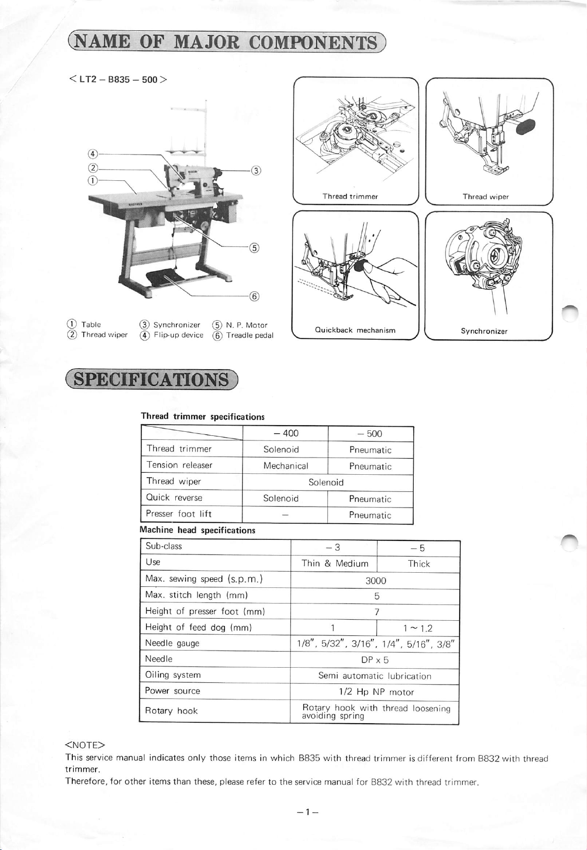
Table
Thread
wiper
@
Synchronizer
(4)
Flip-up
device
(5)N.P.
(6)
Treadle
Motor
pedal
Thread
Quickback
trimmBr
mechanism
Thread
wiper
Synchronizer
Thread
Thread
Tension
trimmer
trimmer
reieaser
specifications
Thread wiper
Quick
reverse
Presser
foot
lift
Machine head specifications
Sub-class
Use
Max.
sewing speed {s.p.m.)
Max.
stitch
length (mm)
Heightofpresser
foot
(mm)
Height of feed dog (mm)
Needle
Needle
Oiling
Power
Rotary
gauge
system
source
hook
-400
S
Solenoid
^
Mechanical
S
Solenoid
-500
Pneumatic
Pneumatic
Solenoid
Pneumatic
Pneumatic
Thin&Medium
1 1-
1.2
1/8". 5/32", 3/16", 1/4", 5/16", 3/8"
DP
X 5
Semi
automatic
1/2
Hp NP
Rotary hook with thread loosening
avoiding
spring
lubrication
motor
<NOTE>
This
service
trimmer.
Therefore,
manual
for
other
indicates
items
than
only
these,
those
itemsinwhich
please refertothe
B835
service
with
manual
thread
trimmerisdifferent
for
B832
with
thread
from
trimmer.
B832
with
thread
Page 3
(ADJUSTING
PROCEDU^
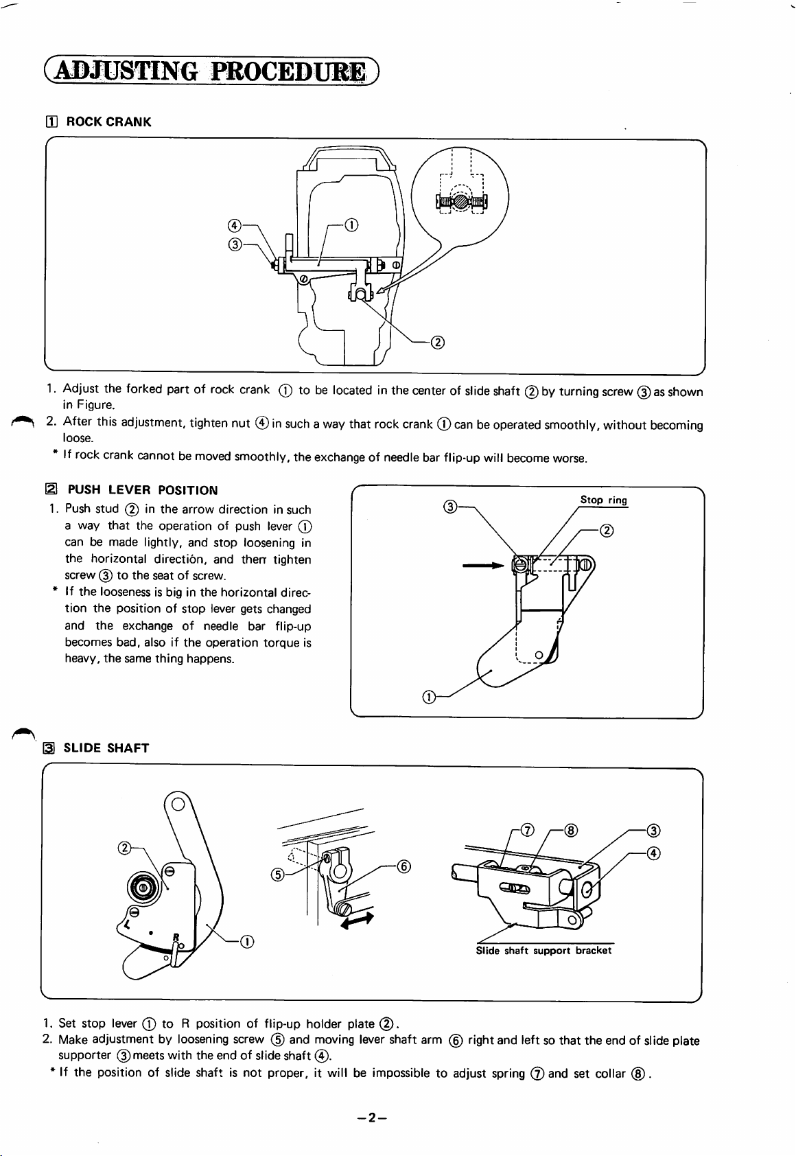
d ROCK
r
1.
Adjust
in
2.
After
loose.
If
11 PUSH LEVER POSITION
1.
a way
can be made lightly, and
the
screw
* If
tion
and
becomes
heavy,
CRANK
the
forked
Figure.
this
adjustment,
rock
crank
Push
stud
that
horizontal direction, and therr tighten
(3)tothe
the
looseness is big in
the
position of
the
exchange
bad,
the
same
partof
tighten
cannotbe
in
the operation of push lever (T)
seat
alsoifthe
the
thing
moved
arrow
of screw.
the
stop
of
needle
happens.
rock
crank
(T)tobe
nut
(4)insuchaway
smoothly,
directioninsuch
stop
loosening in
horizontal
lever gets changed
operation
bar
direc
flip-up
torque
locatedinthe
that
the
exchangeofneedle
is
rock
crank
centerofslide
(T)
canbeoperated
bar
flip-up
(D—\
shaft
will
become
(2)byturning
smoothly,
worse.
Stop
/
li
screw
without
ring
(3)asshown
becoming
V
SLIDE
1. Set stop
2. Make adjustment by loosening screw (5) and moving lever shaft arm (6) right and left so that the end of slide plate
supporter (3)meetswith the end of slideshaft
SHAFT
(D
lever
0 to R position of
(D
flip-up
holder plate
0.
0.
(6)
Slide
shaft
support
(3)
bracket
* If the position of slide shaft Is not proper, it will be impossible to adjust spring 0 and set collar (8).
y
-2-
Page 4

a SLIDE
SHAFT
SUPPORT
BRACKET
(D
(D
1.
Set
stop
lever
to
the
mark
of flip-up
2. Align the left end of slide block
3.
Tighten
* If this position is not proper, release pin and needle bar will be broken.
screw(3)through the hole of slide plate 0 , and tighten
holder
plate.
(T)
with the left end of needle bar support
screw
(D
0 .
LEVER
SHAFT
ARM
SPRING
PRESSURE
(2)
(D
Push
lever
1. When stop lever 0 is released from L or R position, stop lever 0 must stop at the position marked in the center
as
shown
in Figure.
2.
When
stop
lever
0 is set at L or R position, set
collar
@ must be
fixedatwhere
set collar @
lightly
touches
spring®.
3.
The
pressureofspring L
4.Ifstop
lever0does
andRare
notstopat the
same.
position
markedinthe
center,
readjust
the
pressureofspring
0.
-3-
Page 5

NEEDLE
BAR
PUSHER
(D
0.5
(2)
mm
1. When needle bar (T) is at
pusher
0
NEEDLE
@and
the upper end of needlebar
AND
ROTARY
Rotary
hook
point
the
highest position, adjust so that the clearance between the lower end of needle bar
(T)
comesto be0.5mm by turning needle bar pusher
HOOK TIMING
Needle
(D
0.2
mm
(D
0.05
(1) Clearances
1.
Loosen
point
2. When
screws
becomes
the
hook base
•Tighten
screws
mm
between
about
clearance between needle and rotary hook point has been adjusted, adjust
0and
needles
0 0
0.5mm.
and
and
rotary
hook
0
and
move
rotary
spiral gear end 0 to about 0.2 mm.
points
hook
base0until
the
clearance
0 in such a way that its contact remains unchanged.
-4-
(D
between
the
clearance between rotary
®®
needle
and
rotary
hook
Page 6

(2) Clearances between rotary hook and needle plate
1.
Make
adjustmentbyloosening
rotary
hook
(2)and
needle
plate
screws
(3)
(3) Needle bar rise, needle bar height
Needle
1.0''1.5mm
2.4mm
(T)and
becomes
0.6M).9
moving
0.6~0.9mm.
(
(D
mm
rotary
\
>1
hook
(2)upand
down
0
so that the
clearance
between
1.
Set
the
2.
3.
4.
Loosen
from
Set
the
Remove
feedatposition
screws®,and adjust sothat rotary hook point (2)must be at the center of
the
lowest
position.
feedatposition
screw (3), and adjust so that the distance between upper end of needle holeand rotary hook point is 1.0~
"2".
"0".
1.5mmby turningscrew0 when rotary hook point isat the centerof
(4) Clearances between rotary
^
(3)
hook
and
opener
1. The clearance between rotary hook 0 and opener
needle
when needle
needle.
0
must
be about 0.2
pulled back in
the
mm
when
arrow
direction, otherwise loosen
screw0 and adjust the clearance.
opener
rises
@ is
2.4mm
fully
-5-
Page 7

H ANTI-SPINNING SPRING,
KNIFE
DRIVING
CAM
(1) Anti-spinning spring
Anti-spinning spring
little
bit
weak
springascompared
for
LT2—B832,
thread passage in
the
caseofLT2-B835
because
the
than
for
LT2—B835 uses a
the
resistanceoflower
bobbin
LT2-B832.
with
the
one
case is bigger in
Anti-spinning
spring
(2) Knife driving cam
In case of B835—405
shape of knife returning
for
thick
part
designed for anti-spinning of
of
thread
thread.
Another
trimmer
trimmer.
trimming
so as
specifications
is
same
as
nottosupply
of
LT2—B832
materials,
has been specially
bobbinattime
lower
B835
with
thread
with
thread
the
< B835—405
for
thick
material
>
\
(A)
Knife
driving
part
Knife
returning
part
lA)
<Another specification of B835 with thread trimmer >
A
(A)
Knife driving
Z
part
Knife returning
part
(A)
-6-
Page 8

BROTHER
HEAD
NAGOYA,
TELEX:
I
C06C075
PrintedInJapan
INDUSTRIES,
OFFICE:
JAPAN
BROTHER
NO.
35,
J59743
LTD.
9-CHOME
HORITA-DORI
MIZUHO-
 Loading...