

Page 1
e
..
-~·~
.a:.~-'...L=
......
.
Page 2
CONTENTS
[Model
8831 · 8832 · 8835 · 8836 · 8882]
NAMES
C
(SPECIFICATIONS)
OF
MAIN
PARTS).............
. . . . . . . . . . . . . . . . . . . . . . 3
(MECHANISM)...........................
[]Upper
[!)Needle
[!]
[!]
III
[I) Tension releaser mechanism
[II
(!]Thread
[!J
@)Top feed mechanism types
shaft and needle bar mechanism . . . . . . . • 5
feed mechanism . . . . . . . . • . . . . . . . . . . . • . 5
Lower shaft and rotary hook mechanism . . . . . . . 6
Feed
mechanism . . . . . • . . . . . . • • . . . . . . . . . . . . . . . 6
Thread trimmer mechanism . . • • . . . . • . . . . . . • • . . 7
...............•
Reverse mechanism . . . . . . . . . . • . . . . . . • . . . . . . • . 8
wiper . . . . . . . . . . . . . . . . . . . . . . . . . . . . . . . . 8
Needle bar (left and right) mechanism types
8835
and
8836 . .. . ..
..
..
.. . .. ..
883
7 and
..
8838
. .
.. . .. . ..
DISASSEMBLY PROCEDURES 11
B831,B832,B835,B836,8882
[]Cover
[1]
[!]Thread
[!]Rotary
III
[!]Needle
[II
. • . . . . . . . . . . . . . . . . . . . . . . . . . . . . . . . . . . . . .
Presser mechanism . . . . . . . . . . . . . . . . . . . . . . . . . .
wiper . . • . . . . . . . . . . . . . . . . . . . . . . . . . . . . • 12
hook. lower shaft and
thread trimmer mechanism .
Reverse mechanism . . . . . • . . . . . . • . . . . . . . . . . . . •
bar rocking shaft mechanism . . . . . . . . . . .
Reverse switch mechanism . . . . . . . . . . . . . . . . . • . 1 5
• . . . . . . . . . . . . • • . . . 12
Page
;.
10
11
11
14
15
1
STANDARD
ADJUSTMENTS . . . . .
25
B831,B832,B835,B836,B882
lil
Needle and feed
5
7
(1]
Adjustment
(Models
[!]Needle
[!]
Rotary hook to needle plate gap . • . . . . . . . . . . . . .
II]
Rotary hook to bobbin case opener gap . • • . . . . .
[!]Presser foot height adjustment . . . . . • . . . . • • . . . .
[II
Feed
(!]Tension
[!]Stitch
(!ID
Reverse feed soleno1d adjustment . . . . . . . . . . . . .
8831.
and rotary hook timing adjustment • . . . . .
dog height adjustment
release adjustment . • . . • . . . . . . • • . . . . . .
length adjustment . . . . . . . . . • • . . . . . . . . . • .
[ill Thread wiper adjustment . . . . . . . . . . . . . . . . . . . . .
9
lliJ
Slider adjustment . . . . . . . . . . . . . . . . . . . . . . . . . . . .
[!!]Movable and fixed
IE)
Knife mam lever roller . . . . . . . . . • . . . . . . . . . . . . . .
ffi)
Knife drcving lever adjuStment . . . . . . . . . . . . . . . . .
@]
Position detector adjustment . . . . . . . . . . . . . . . . . . 43
ill)
Corner sewmg
(8835.
[!!]
Timmg belt replacement • . . . . . . . . . . . . . . . . . . . . . 4 7
8836)
t1mmg
(8831)
of
needle bar to presser bar gap
8832.
8835.
kn1fe
adjustment . . . . . . . . . . . .
pos1t10n
.. . ..
adjustment
. . .
.. . .. .. ..
. . . . . . . . . . . . . . . .
8836.
8882)
..
..
. . • • . •
..
. . .
. . . . .
..
. . . .
..
.. . .. .. ..
25
28
29
31
31
32
33
34
35
36
37
39
40
42
42
43
(ASSEMBLY
[]Needle
[1]
Lower shaft. thread trimmer and
rotary hook mechanism . . . . . . . . . . . . . . . . . . . . .
[!]
Presser mechanism . . . . . . . . • . . . . • . . . . . . . . . . . •
[!]Thread
(1]
Reverse switch mechanism . . . . • . . . . . . . . . . . . . .
[!]Reverse mechanism . . . . . . . . . • . . . . . . . . . . . . . • . .
[II
Cover • . . . . . . . . . • . . . . . . • . . . • . . . . . . . . . . . . . . . . .
bar rocking mechanism . • . . . • . . . . . . . • . . 16
wiper
PROCEDURES)
.......••.....................••
...........
• .
16
16
21
21
23
23
24
\/
Page 3
CONTENTS [Model
8837 · 8838]
DISASSEMBLY PROCEDURES
......
B837,B838
[I) Cover . . . . . . . . . . • . . • . • • . . . . . . . . . . . . . . . . . . . . . .
[!]Tension
[II
Presser foot and walking bar . . . . . . . • . • . . . . . . . .
fl]
Needle bar and needle thread take-up . . . . . . . . .
[I]
Feed
(ASSEMBLY
[I)
Feed
[!]Needle
[II
Walking bar and presser foot . . . • . . . . . . . . . . . . . 53
fl]Tension
[!]Cover
STANDARD
release lever . . . . . . . . . . . . . . . . . . . . . . . . .
assembly . .
assembly . . . . . . . .
bar . . . . . . . . . . • . . . . . . . . • . • . • . . • . . . . . • • 52
release lever
.•...•....•..•...•.•..•••..............
..
. . . . . . • •
PROCEDURES)
..
. .
.. ..
. .
..
...........
..
. . . . . . • . . . . . . . . . . . . . . 52
.........................
ADJUSTMENTS ..
. . .
..
.. ..
. . ..
B837,B838
Page
48
48
49
49
51
51
52
57
58
59
GAUGE PARTS LIST
DOUBLE NEEDLE
FOR
LOCK
STITCH
SEWING MACHINES
(OTHERS).................................
[I) Top cover thread guide
[!]Adjusting
[II
Anti-spinning spring
fl]8obbin
ITlTo thread bobbin cases (8835.
upper thread length • . . . . . . . . . . . . . . . • 75
......................•......•........
(TROUBLESHOOTING
.. • .. .. .. • .. .. ..
.. . .. . ..
..
..
8836)
GUIDE)
• . .
..
_,
.....
.. . ..
. . .
.. . ..
........•
.........
..
. 76
67
75
75
76
76
77
[I) Needle and feed timing adjustment (standard) . . 59
[!]Feed
[II
fl]
11]
[!] Presser foot height adjustment . • . . . . • • . . . . . . . .
II]
II]
1IJ
[!ID
dog adjustment m back and forth
directions . . . . . . . . . . . . . . . . . . . . . . . . . . . . . . . . . . .
Needle and rotary hook timmg adjustment . . . . . .
Clearance between rotary hook and
needle plate . . • . • . . . . . • . . . . . . . . . . . . . . . . . . . . . .
Clearance between rotary hook and
bobbin .case opener . . . . . .
Feed
dog height adjustment . . . . . . . . . . . • . . . . . .
Vibrating presser foot and lifting presser foot
and
needle timing adjustment . . . . . . . . . • . . . . . . •
Upper feed adjustment
Vibrating presser foot and lifting presser foot
vertical stroke adjustment . . . . . . . . . . . . . . . . . . . . .
• . . . . . . . . . . . . . . . . . . . 62
..
. • •
..
. .
.. .. . ..
. . . .
.. . 65
60
61
62
63
64
65
66
Page 4
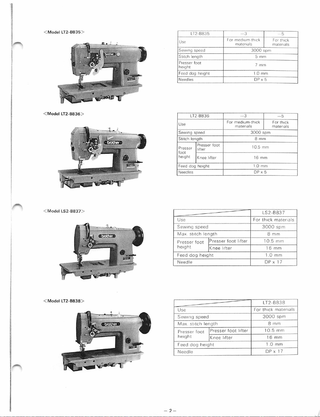
( NAMES
OF
MAIN PARTS )
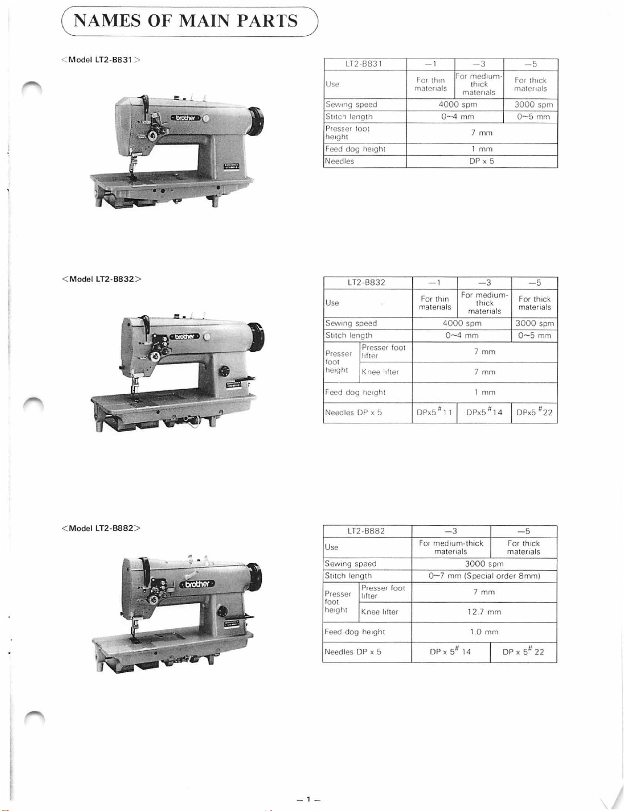
< M odel LT2-B831 >
Mod
el
<
LT2-B832
Ll2B831
Use
Sew1ng
speed
Sutch length
Presser foot
he1ght
Feed
dog he1ght
Needles
>
LT2-B832
Us
e
Sew1ng
speed
Stitch length
Presser
fo
he1ght
f---
reed dog
Presser foot
lifter
ot
Knee lifter 7 mm
he1ght
- 1
for
thon
matenals
4000
-1
For th1n
matenals
For
med1um-
th
matenals
spm
0-4
mm
7 mm
1
DP X 5
For med1
matenals
4000 spm
0-4
mm
7
1 mm
3
iCk
mm
- 3
thi
Ck
mm
um-
-5
For
th1ck
matenals
3000
spm
0-5
mm
-5
For t
h1ck
matenals
3000
spm
0-5
mm
<
Model
LT2-B882
es
Needl
>
Use
Sew1ng speed
St1tch length
Pre
foot
he1ght
Feed
Needles
DP x 5
LT2
-8882
Presser foot
sser
l1fter
Knee lifter 12 7 mm
dog
he1gh
t
DP x 5
DPx5 # 1 1 DPx5 li
-3 -5
med1um-t
For
matenals matenals
Q-7
mm
DPx
51i
14
DPx5
h1ck
3000
(Spec1al order 8mm)
7
10
14
spm
mm
mm
Fo
r t
h1ck
DP X 5fj 22
li22
_, _
Page 5
<
<
Mod
Mod
el LT2-
el LT2-
B835
B836
>
>
LT2-B835
Use
speed
Sewtng
Stnch
length
Presser foot
hetght
Feed dog hetght 1.0
Needl
es
LT2-
B836
Us
e
Sewtng
speed
Sutch length
Presser
Presser
foot
hetght
Feed d
Needles
og
foot
lifter
Knee lifter 16
hetght
medtum-lh
For
matenals
med
For
matena
- 3
3000
- 3
turn-thtck
ls
3000
105
DP X 5
1.0
DP
tck
5 rnm
7 rnrn
mm
8
mm
mm
mm
X 5
spm
spm
mm
5
ro
r thtck
matenals
- 5
For thtck
matenals
<
Mod
<
Model
el LS2-B837
LT2-B838
>
U
se
Sewmg
Max. stttch l
Presser
he1ght
Feed
dog
speed
ength
foot
he1ght
!Presse r
!
Knee
lifter
foot
l1f
ter
Needle
>
Use
w111
g speed
S e
Max .
StitCh
length
l
ift
Pr
esser
he1ght
Feed d
N
eedle
foot lPresser
IK
nee l1fter
og
he1ght
foot
er 10
LS2 -
For th1
3000
10
DP X 17
L
th1
For
3000
B837
ck
mat
spm
8
mm
.5
mm
16
mm
1.0
mm
T2-B838
ck
mater
spm
8
mm
.5
mm
16
mm
1.0
mm
DP X 17
ena
ls
1als
- 2 -
Page 6
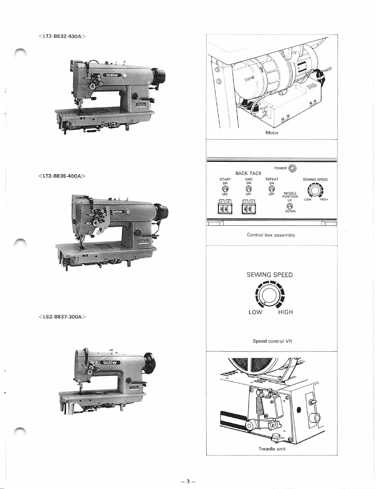
< LT2-B832-
<
LT2-BB35-400A
400A
>
M
otor
POWI:R
B
ACK
>
START
ON ON
@ @
OFF OFF
TACK
END
REPEAT
ON
@
OFF
~
NFEOLE
POSITION
UP
@
OOWN
S
E'MNG
SPEED
,.
....
~
(~'
~
lOW
HIGH
S2-B837-300A
< L
I
r--"YI
Control box assembly
'Ej
SEWING SPEED
~----~
(M:
L
>
OW
Speed c
ontr
HIGH
ol
VR
-3-
Treadle
unit
Page 7
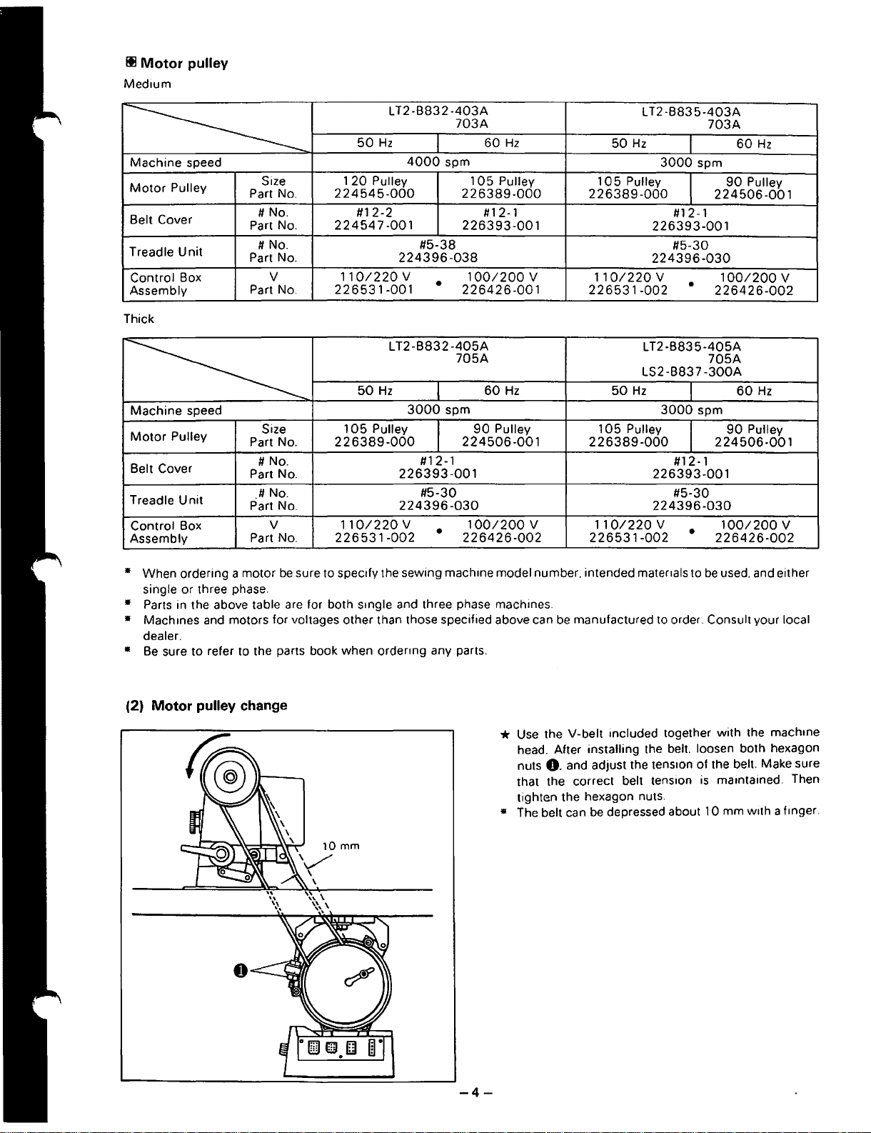
Ill
Motor
Med1um
Machine
---------------
Motor
Belt Cover
Treadle
Control Box
Assembly
Thick
pulley
speed
Pulley
Unit
Size
Part No.
#No.
Part No.
#No.
Part No.
v
Part No.
LT2
50
Hz
1
20
Pulley
224545-000
#12-2
22454
7-001
224396-038
110/220V
226531-001
-B832
4000
#5-38
-403A
703A
spm
105
226389-000
226393-001
100/200
•
226426-001
60Hz
Pulley
#1
2-1
v
L
T2
50
Hz
105
Pulley
226389-000
226393-001
224396-030
110/220
226531
-002
-B83
3000
v
5-403A
I
spm
l
#12-1
#5-30
•
703A
60Hz
90
Pulley
224506-001
100/200
226426-002
v
LT2-B832-405A
50
Hz
Machine
----------
Motor
Belt Cover
Treadle
Control Box
Assembly
• When ordering a motor
single or three phase.
• Parts in the above table
• Machines
dealer.
•
Be
(2)
speed
Pulley
Unit
Size
Part No.
#No.
Part No.
.#No.
Part No.
v
Part No.
be
sure to specify the sewing
are
and
motors for voltages other than those specified above can
sure to refer to the parts book when ordermg any parts.
Motor
pulley change
105
226389-000
110/220
226531-002
for both smgle and three phase machines.
3000
Pulley
226393-001
224396-030
v
I
spm
I
#1
2-1
#5-30
•
mach1ne
705A
60Hz
90
Pulley
224506-001
100/200
226426-002
v
model number. intended matenals to
be
*
Use
the V-belt included together with the machme
head. After installing the belt. loosen both hexagon
nuts
0.
and adjust the
that the correct
tighten the hexagon nuts.
• The belt can
50
105
226389-000
110/220
226531-002
manufactured
be
depressed about 10 mm
LT2-B835-405A
LS2-B837
Hz
Pulley
I
3000
I
#12-1
226393-001
#5-30
224396-030
v
•
to
order. Consult your local
tens1on
belt tension
705A
-300A
60Hz
spm
90
Pulley
224506-001
100/200
226426-002
be
used. and either
of the belt. Make sure
is
mamtained. Then
v
w1th a f1nger.
-4-
Page 8
""- 1
l'
J.
.c,
~
J-.
J-\. 1
''U,::,
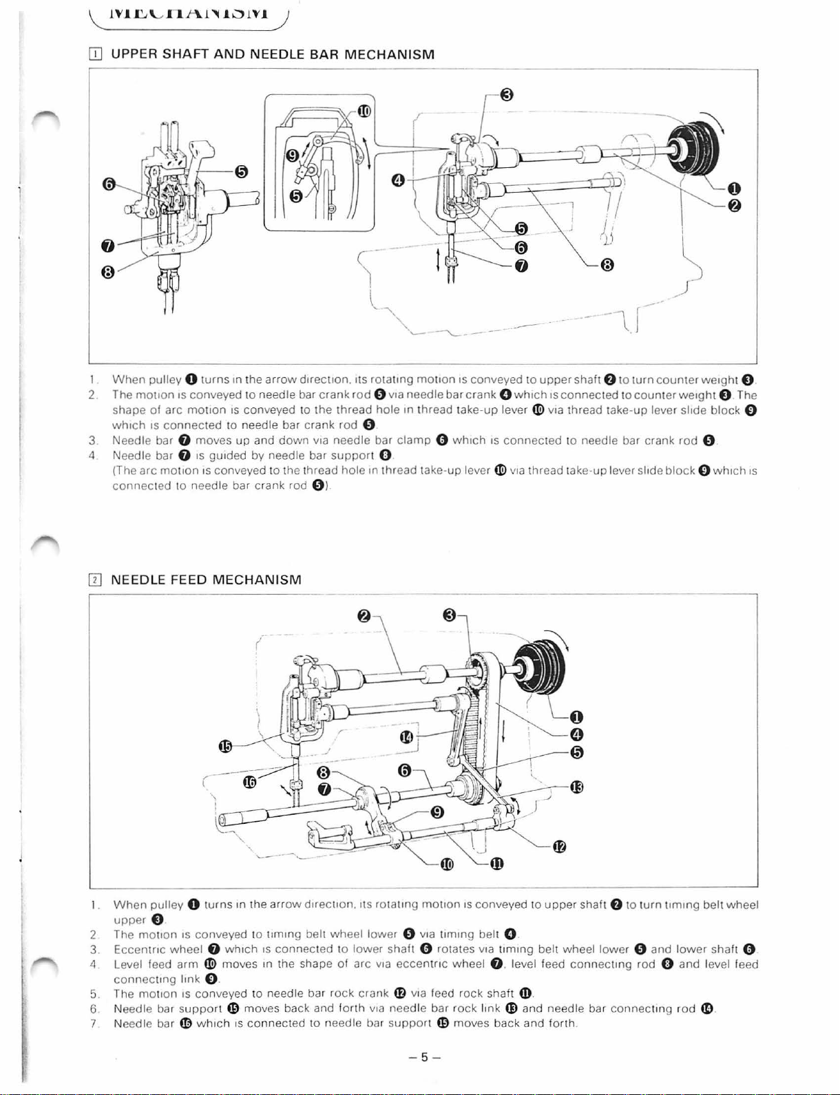
[I]
UPPER
I
When
2 The
shape
wh1ch
SHAFT
pulley 0 t
motion
of
1s
connec
arc
1S
motion
AND
urns
conveyed
ted to need
3 Needle bar 0 moves
4 Needle bar 0
(The
arc
connec
ted
motion
to
needle bar
IS
gu1ded by needle bar
1s
conveyed
rn
)
NEEDLE
m the
arrow
to
needle bar
1s
conveyed to the thread
le
up
and
crank
BAR
d1rect1on. Its rotatm g
crank
bar
crank
rod
down
v1a
needle
support
to
the thread
rod 0 l
MECHANISM
rod 8v1a
hole
needle bar
1n
0
bar
clamp
0
hole
m thread take-
motion
thread tak
IS
0 wh1ch
up
--
conveyed to
crank
O wh1ch
e-up
lever ~ v1a
IS
connected
lever ~ v1a
---
--~.r
upper
shaft
f)
to
1s
connected
thread take-up lever sl1de
to
needle bar crank
thread take-
up
lever slide
turn
to
counter
----
counter
we1ght 0 The
rod
block
0
@
we1ght 0 .
block
0
0
0 wh1ch
1s
[I) NEEDLE FEED
When
pulley
0 t
upper
0
2 The
3 Eccent
4 Level feed
5 The moti
6 Needle bar su
7 Needle bar
mouon
connec
IS
conveyed to
r1c
whee
arm ~ moves m the shape ol arc v
tmg
link
on
IS
conveyed
pport
fD
wh1ch
MECHANISM
urns
1n
the
l 0 wh1ch
O.
to
G)
mo
ves back and
IS
connec
arrow
d1rect10n. ItS
t1m1ng
belt
wheel lower
1s
connec
ted
needle bar
ted to needle bar s
rock
to
lower
forth
rotating
0 v1a
shaft 0 rotates v
1a
eccen
cran k
41)
VIa feed ro
VIa
needle bar rock
upp
motion
tlmmg
triC
ort
G)
IS
conveyed
belt 0
wheel
ck shaft
moves
to
1a
t1m1ng
belt wheel
0 . level feed
m.
lmk m and
back
and
upper
shaft
connectmg
needle bar
forth
.
f)
to t
urn
lower 0 and
rod 0 and
connec
ting
t1m1ng
lower
rod
belt
wheel
shaft 0
level feed
4D
- 5 -
Page 9

[I]
LOWER
SHAFT
AND
ROTARY
HOOK
MECHANISM
1.
When
upper
2. The
3. As
4. Rotary
(Opener)
1. Open
2. Op
IT]
moti
lower shaft 0 which
ener
• The
FEED
pu
lley 0 turns in
0 .
on
is conveyed
h
ook
~
rotates via pini
er
crank
41)
move
4D
which
LS2-B837
MECHANISM
s in the
is conn
sewing
th
e ar
to
tim
is
connec
ected
machine
______=::~~
row
direc
tion. its r
ing
belt
wheel
ted to
on
gear 0 which
shape
of
to
opener crank
does not contain a left side
----
ota
lower
tim
ing
belt
an arc via
41)
is
----~
ting
mot
0 via t
wheel l
connec
rota
ry
moves
---~
ion
is
conveyed
imi
ng
belt
ower 0 rotat
ted to rotary h
hook ~ and
in
the
shape
rotary
i
to
upper
sha
ft
f)
to
turn
timing
0 .
es. spiral
ook
ope
ner
of
an ar
hook. etc. because of the one needle.
gear
base O.
link
$ .
c.
8 is turn
ed
.
belt
whee
l
1.
When
pu lley 0 t
upper
O.
2. The motion IS conv
3. Eccentric
4. Level feed
connect
5. Feed bar
6. Feed bar fork
7.
The moveme
ing link 0 .
ur
ns in the
eyed
wheel 8 whi
arm
«!)
moves in the sh
41)
moves b
4D
moves
nt
of feed
to timmg
ch is con
ack
and
up
dog
arrow
directio
belt
nec
ape
forth via
and down
1s f1xed
by the comb
n.
its
rotating
wheel lowe
ted to
lower shaft 0 rot
of
an
arc
feed ro
ck
by vertical feed
r 0 via t
via
eccentric
shaft
inati
on
motio
tD
.
ecce
of
n IS
imi
ng bel t 0 .
ates via t
wheel
ntri
C w heel m whi
move
ments in
- 6 -
conveyed
imi
ng belt wheel lower 0 a
8 . level feed
to upper sh
Ch
IS
1tem
5 and 1tem 6.
aft
connec
connec
f)
ting r
ted
to t
urn timi
nd
od
0 and level feed
to
lower
ng
belt
wheel
lower shaft
shaft o.
0 .
Page 10
i
l
l
r
I
I
r
!
i
!
~.
~
IT]
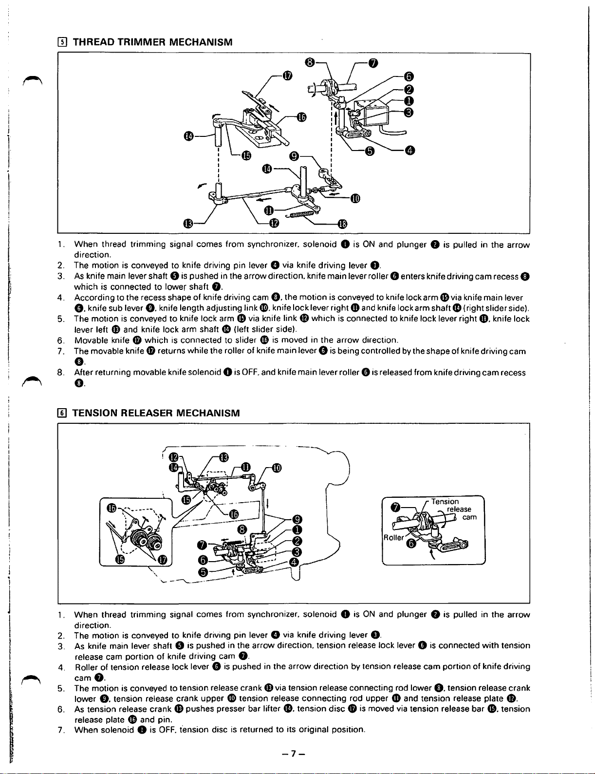
THREAD TRIMMER MECHANISM
1.
When thread trimming signal comes from synchronizer. solenoid 8
direction.
2.
The motion
3.
As
knife main lever shaft 8
which
According to the recess shape of knife driving cam
4.
8.
knife sub lever
The motion
5.
lever left
Movable knife
6.
The movable knife
7.
is
conveyed to knife driving pin lever 8 via knife driving lever
is
pushed in the arrow direction. knife main lever roller 8 enters knife driving cam recess e
is
connected to lower shaft
0.
knife length adjusting link
is
conveyed to knife lock arm
G)
and knife lock arm shaft
0 which
is
connected to slider
8.
6)
G)
(left slider side).
e.
the motion
CD.
knife lock lever right
via knife link
fD
is
moved in the arrow direction.
4B
0 returns while the roller of knife main lever 8
e.
After returning movable knife solenoid 8
8.
is
OFF.
and knife main lever roller G
e.
is
ON
and plunger 8
8.
is
conveyed to knife lock arm
4D
and knife lock arm shaft
which
is
connected to knife lock lever right
is
being controlled
is
released from knife driving cam recess
is
pulled in the arrow
6)
via knife main lever
G)
(right slider side).
49.
knife lock
by
the shape of knife driving cam
I
I
.
I
l
J
I
I
~
[[]
TENSION RELEASER MECHANISM
When thread trimming signal comes from synchronizer. solenoid 8
1 .
direction.
The motion
2.
As knife main lever shaft 8 is pushed in the arrow direction. tension release lock lever 0
3.
release cam portion of knife driving cam
Roller of tension release lock lever 8
4.
cam8.
The motion is conveyed to tension release crank
5.
lower
As
tension release crank
6.
release plate
When solenoid
7.
is
conveyed to knife driving pin lever 8 via knife driving lever
0.
tension release crank upper
G)
pushes presser bar lifter
fD
and pin.
8
is
OFF.
t'ension disc
8.
is
pushed in the arrow direction by tension release cam portion
G)
via tension release connecting rod lower
CD
tension release connecting rod upper
41).
tension disc 0 is moved via tension release bar
is
returned to its original position.
is
ON
and plunger 8 is pulled in the arrow
0.
is
connected
of
e.
tension release crank
4D
and tension release plate
with
tension
knife driving
8.
41.
tension
-7-
Page 11
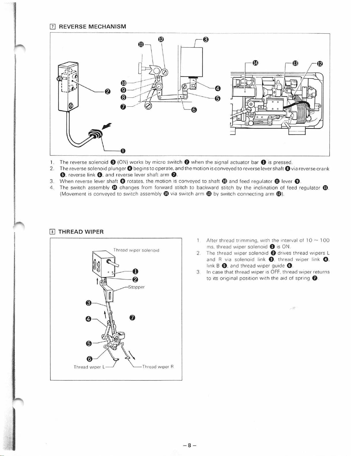
[I]
REVERSE MEC
HANISM
~0
1. The reverse solenoid 0 (ON) works by
2. The reverse
solenoid
plunger
0 begins
micro
to
0 . reverse link 0 . and reverse lever shaft arm G.
3.
Wh
en reverse lever shaft 0 rota tes. the
4. The
[!]
switch
(Movement
THREAD
assembly
is
conveyed to switch assembly
«)
changes from forward
WIPER
Thread w1per soleno1d
switch 0
operate. and the
motion
is
conveyed to shaft
stitch
«)
via Switch arm
when
the signal actuat
mot
ton
is
conveyed to reverse lever shaft 0 via reverse crank
«!>
to backward stitch by the inclination
4f}
by
SWitCh
Afte r thread trtmmtng. w
ms. thread w1per solenotd 0
2 The thr ead w1per solenotd
1ts
v1a
orig
and R
ltnk B 0 . and
3 In case th
to
or
bar 0 is pressed.
and feed regulat
connec
solenotd lmk 0 . thread wiper li
thr
ead
at
thread
tnal posttt
ting
w1per
wipe
on
or
arm
1th
the mterval of 1 0 - 1
f)
guide 0 .
r 1s
OFF.
wtth the
4D
lever 0 .
of
feed regulator
fD
).
1s
ON.
dr1ves
thread w1pers L
thread wiper returns
a1d
of
spnng
nk
G.
4!)
00
0 .
.
Thread
Thread w1per L
w1per R
-8-
Page 12
l
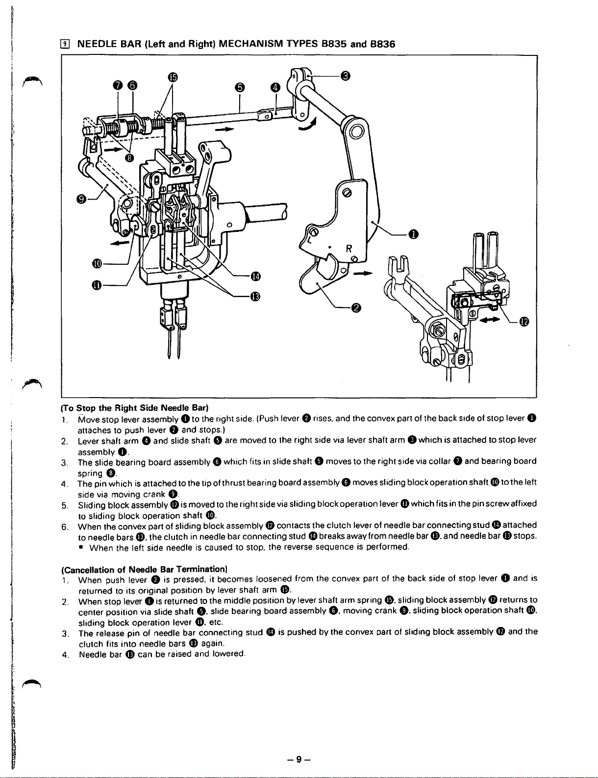
[[]
NEEDLE BAR
(left
and Right)
MECHANISM
TYPES
8835
and
8836
I
I
J
J
I
I
(To Stop the Right Side Needle Bar)
1.
Move stop lever assembly 0 to the right side. (Push lever
attaches to push lever
2.
Lever shaft arm 8 and slide shaft 0 are moved to the right side via lever shaft arm 8 which is attached to stop lever
assembly
3.
The slide bearing board assembly 8 which fits in slide shaft 0 moves to the right side via collar 8 and bearing board
spring
4. The pin which is attached to the tip of thrust bearing board assembly 8 moves sliding block operation shaft
side via moving crank
5.
Sliding block assembly
to sliding block operation shaft
6.
When the convex part
to needle bars
• When the left side needle
(Cancellation
1. When push lever
returned to its original position
2.
When stop lever 0 is returned to the middle position by lever shaft arm
center position via slide shaft
sliding block operation lever
3. The
clutch fits into needle bars fl) again.
4. Needle bar G) can
O.
0.
fl). the clutch in needle bar connecting stud
of
Needle Bar Termination)
release pin of needle bar connecting stud
f)
and stops.)
0.
48
is moved to the right side via sliding block operation lever
G).
of
sliding block assembly
is
caused to stop. the reverse sequence
f)
is
pressed. it becomes loosened from the convex part
by
lever shaft arm
0.
slide bearing board assembly
CD.
etc.
fB
41
be
raised and lowered.
f)
rises. and the convex part of the back
CD
which fits in the pin screw affixed
contacts the clutch lever of needle bar connecting stud
41
breaks away from needle
is
performed.
of
bar~.
the back side
s1de
of stop lever 0
and needle bar fl) stops.
of
stop lever 0 and is
CD.
spring&.
0.
moving crank
is
pushed by the convex part of sliding block assembly
sliding block assembly
0.
sliding block operation shaft
G)
41
fB
CD
to the left
attached
returns
G>.
and the
to
-9-
Page 13

.,
[@]
TOP
FEED
MECHANISM
TYPES
8837
AND
8838
1.
When
mach i
ne
pulley 0
of
rotation
2. The top feed eccentric wh
3. Motion
4. Bell crank link
5.
Th
e top feed presser link 0 is
feed presser bar
6.
Middle
By
loosening
7.
crank 0 is changed and alterati
top feed eccentric wheel 0 .
is conv
presser @ affixed to top feed presser bar
eyed to bell cra nk
f)
causes the up-
Q)
.
wing
nut
turn
s in the direction of the arrow. the rotation is conveyed to
ee
l crank 0 is moved in an arc by
f)
via
top feed shaft 0 which is affixed to t
down mot
gu
1ded by the
CD
and adjusting the
on
of the
10n
of
groove
position
amount
top feed presser link 0 via bell crank 0 .
Q)
of up-
top
feed eccen tric wheel 0 . via t
(oval) of middle presser gu1de
IS caused to move
of
hinge screw m. the
down
motion
of
up
and
middle
amount
upper
shaft 0 and causes the
op
feed con necting rod 0 .
op feed ecce
plate
down
presser @ becomes possible.
ntri
c wheel crank 0 .
~
and conveys mot1on to t
.
of
motion
of
top feed eccentriC
op
-
10-
Page 14
~
UISASS.EMHL
Y .PKUC.EU
lJK.ES)
• These disassembly procedures are for model l
disassembled on the basis of these procedures.
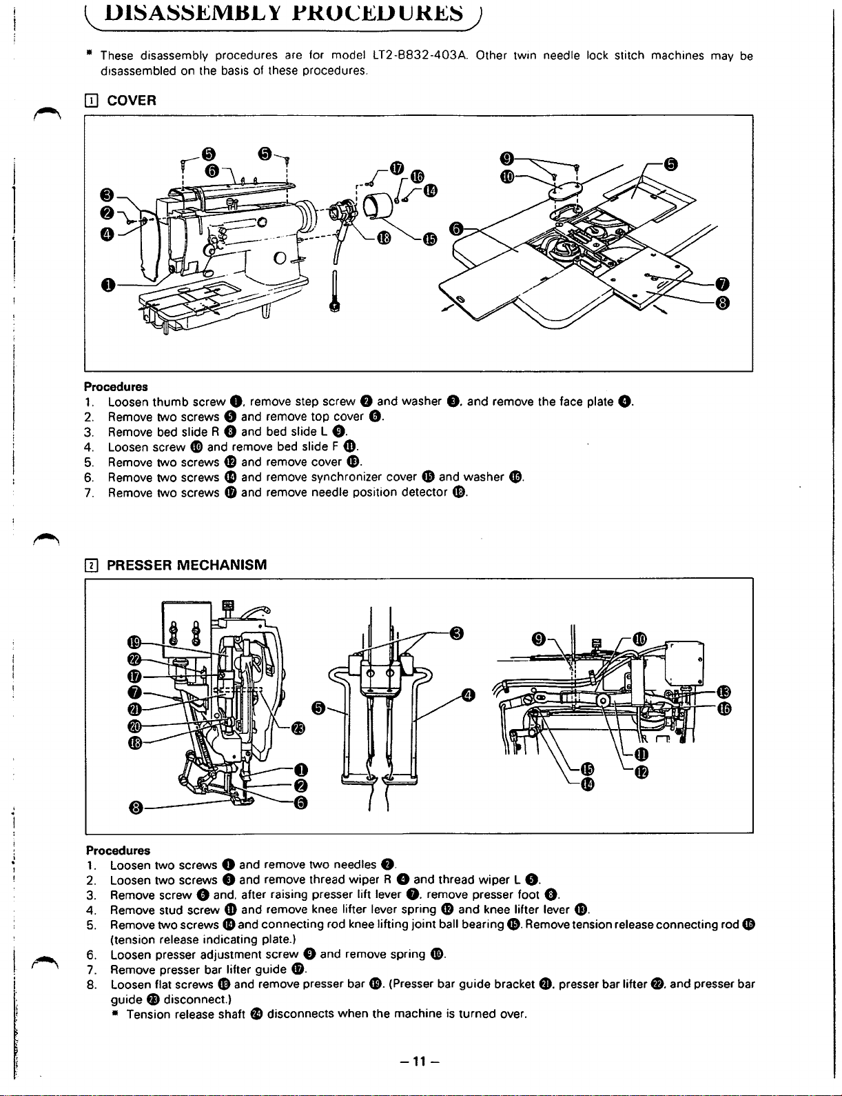
ITJ
COVER
Procedures
1.
Loosen thumb screw
2.
Remove two screws 8 and remove
3.
Remove bed
4. Loosen screw
5.
Remove two screws
6.
Remove two screws
7.
Remove two screws
slideR
0.
remove step screw 8 and washer
G and bed slide L
Cl)
and remove bed slide F
4B
and remove cover
CD
and remove synchronizer cover
41
and remove needle position detector G).
top
cover
0.
4]).
G).
0.
T2
-8832
-403A. Other twin needle lock stitch machines may
8.
49
and washer
and remove the face plate
(D.
8.
be
[]]
PRESSER MECHANISM
Procedures
1.
Loosen two screws 0 and remove two needles
2.
Loosen two screws 8 and remove thread wiper R 8 and thread
3.
Remove screw 0 and. after raising presser lift lever
4. Remove stud screw
5.
Remove two screws
(tension release indicating plate.)
6. Loosen presser adjustment screw
7.
Remove presser bar lifter guide
8.
Loosen flat screws G) and remove presser bar
fJ)
guide
• Tension release shaft e disconnects when the machine
disconnect.)
CD
and remove knee lifter lever spring
48
and connecting rod knee lifting
0 and remove spring
8.
f).
8.
joint
G).
(Presser bar guide bracket
wiper
L
8.
remove presser foot
CD
and knee lifter lever
ball bearing
Cl).
is
turned over.
8.
Remove tension release connecting rod
0.
G).
fD.
presser bar lifter fl. and presser bar
CD
-11-
Page 15
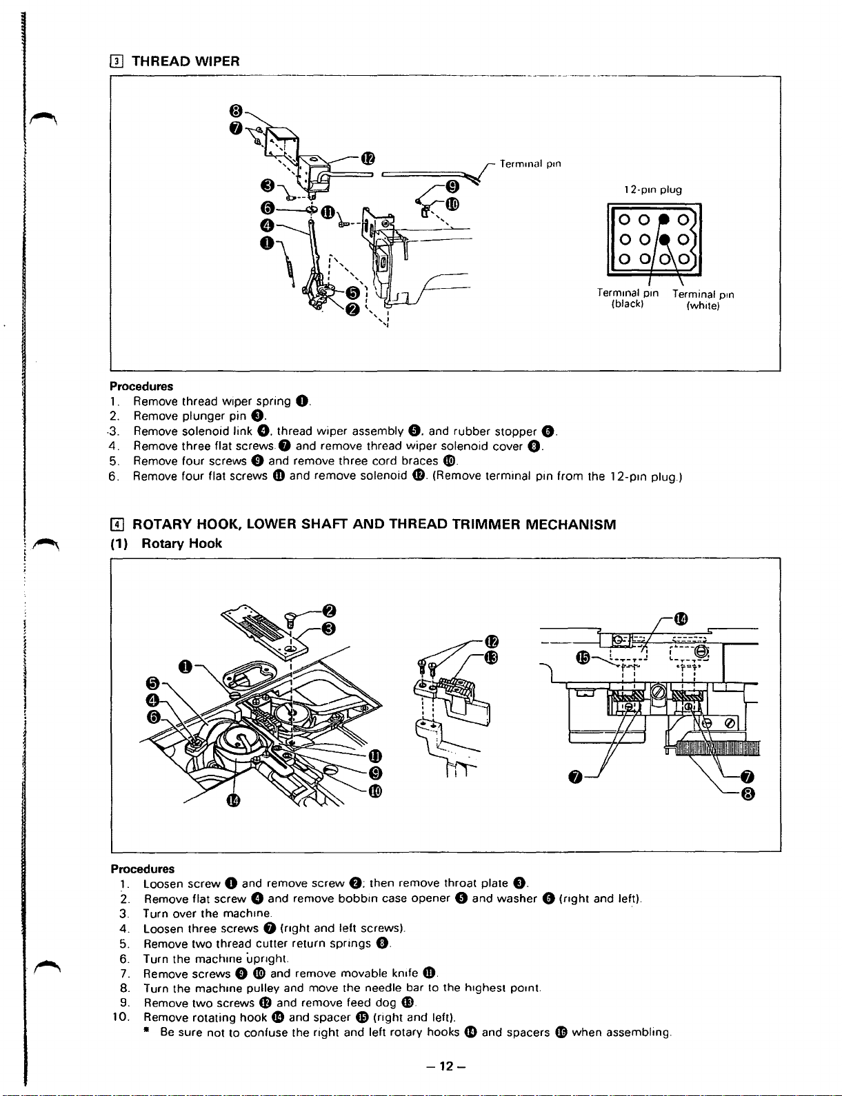
[!]
THREAD WIPER
trri-==f)~
c:====~~
.reD
c(~a.>
Procedures
1.
Remove thread wiper spring
2.
Remove plunger pin
-3.
Remove solenoid link
4.
Remove three flat screws 8 and remove thread
5. Remove four screws 0 and remove three cord braces
6. Remove
ffi
ROTARY HOOK, LOWER SHAFT
four
flat screws
O.
(1) Rotary Hook
O.
0.
thread
wiper
CD
and remove solenoid
assembly
AND
THREAD
0.
wiper
f).
Termrnal
.........
and rubber stopper
solenoid cover
0.
0.
(Remove terminal pm
TRIMMER
MECHANISM
prn
0.
12-prn
Termmal prn Terminal
(black) (white)
from
the 12-p1n plug.)
plug
p1n
Procedures
1.
loosen
2.
Remove flat screw 0 and remove
3. Turn over the mach1ne.
4.
loosen
5.
Remove
6. Turn the mach1ne
7.
Remove screws 0 0 and remove movable
8. Turn the machme pulley and move the needle bar to the h1ghest pomt.
9.
Remove
10. Remove rotating hook
•
screw 0 and remove screw
three screws 8
two
thread cutter return
two
screws
(nght
upnght.
CD
and remove feed dog
fD
Be
sure not to confuse the
bobbin
and left screws).
spnngs
and spacer
right
and left rotary hooks
f);
then remove throat plate
case opener 0 and washer 0
0.
kn1fe
CD.
CD.
CD
(right and left).
fD
and spacers
-12-
0.
(nght
and
lef_t).
CD
when assembling.
Page 16
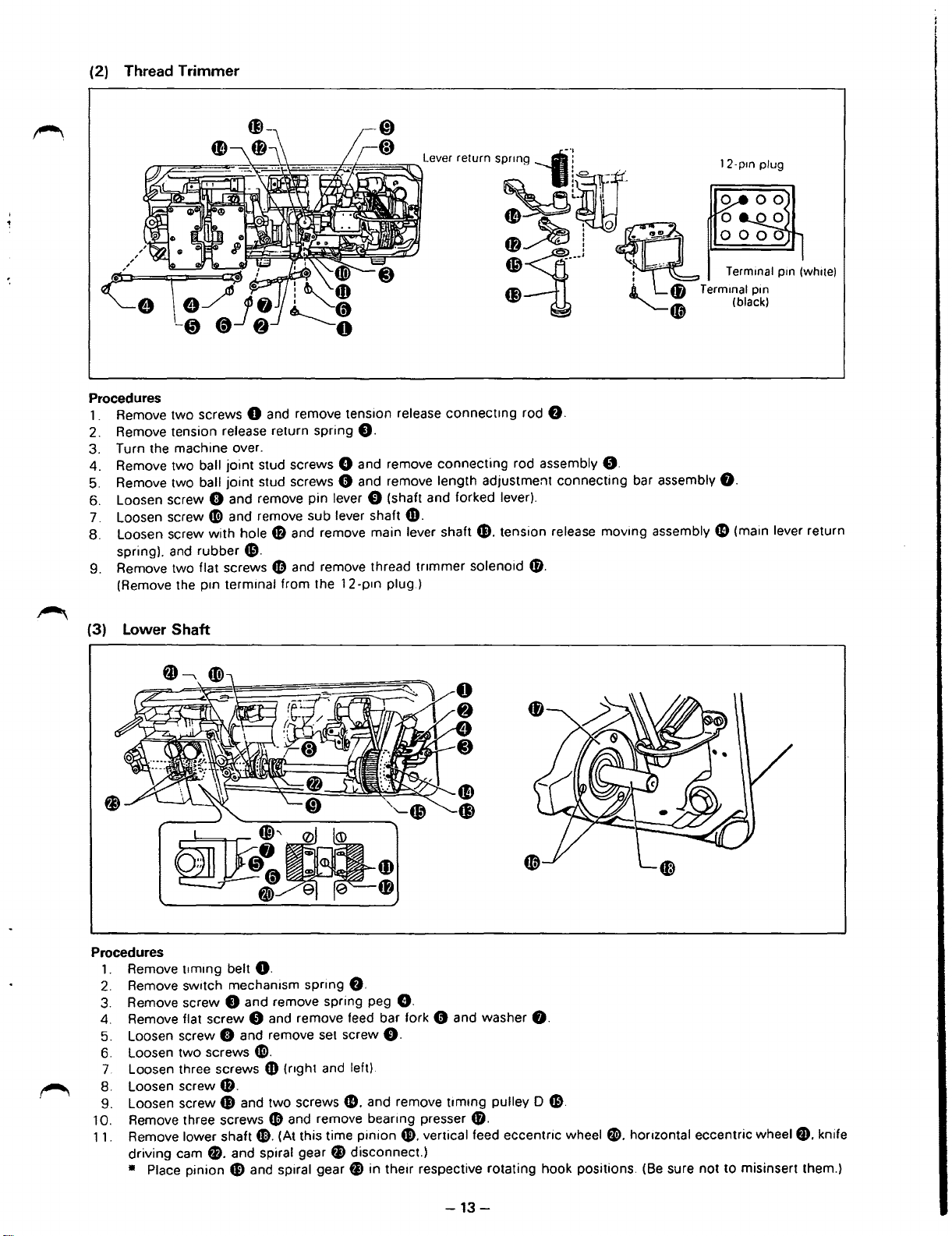
(2) Thread Trimmer
lever
relurn
s~l~lf
-~~~~
fB~!
~~---•
C) A L
Procedures
1 . Remove two screws 0 and remove tension release connectmg rod
2. Remove tension release return spring
3. Turn the machine over.
ball
joint
4. Remove two
5. Remove two ball joint stud screws 0 and remove length adjustment connecting bar assembly
6. Loosen screw 8 and remove pin lever 0 (shaft and forked lever).
7. Loosen screw
8. Loosen screw
spring). and rubber
9. Remove two flat screws
(Remove the prn terminal from the 12-prn plug.)
41)
with
stud screws 0 and remove connecting rod assembly
and remove sub lever shaft
hole$
and remove main lever shaft fl. tension release moving assembly e (main lever return
Gl.
4D
and remove thread tnmmer solenoid
0.
fD.
8.
(D.
0.
.
-~
:
-~
fB
~(@
T ermrnal prn
12-prn plug
T ermmal pm (whrte)
(black)
8.
(3) Lower Shaft
Procedures
1.
Remove
2.
Remove switch mechanism sprrng
3.
Remove screw 0 and remove spring peg
4.
Remove flat screw 0 and remove feed bar fork 0 and washer
5. Loosen screw 8 and remove set screw
6. Loosen two screws
7.
Loosen three screws
8. Loosen screw
9. Loosen screw G) and two screws
10. Remove three screws
11. Remove lower shaft 1). (At this time pinion
driving cam
• Place pinion G) and spiral gear
t1mrng
belt
8.
41).
fD
8.
fl. and spiral gear
G.
O.
f).
(nght and left)
e.
and remove timrng pulley 0
fD
and remove beanng presser
G>.
f1
disconnect.)
fi
in therr respective rotating hook positions.
vertical feed eccentric wheel fl. horrzontal eccentric wheel
fD.
8.
Gl.
(Be
sure not to misinsert them.)
fD.
knife
-13-
Page 17
L
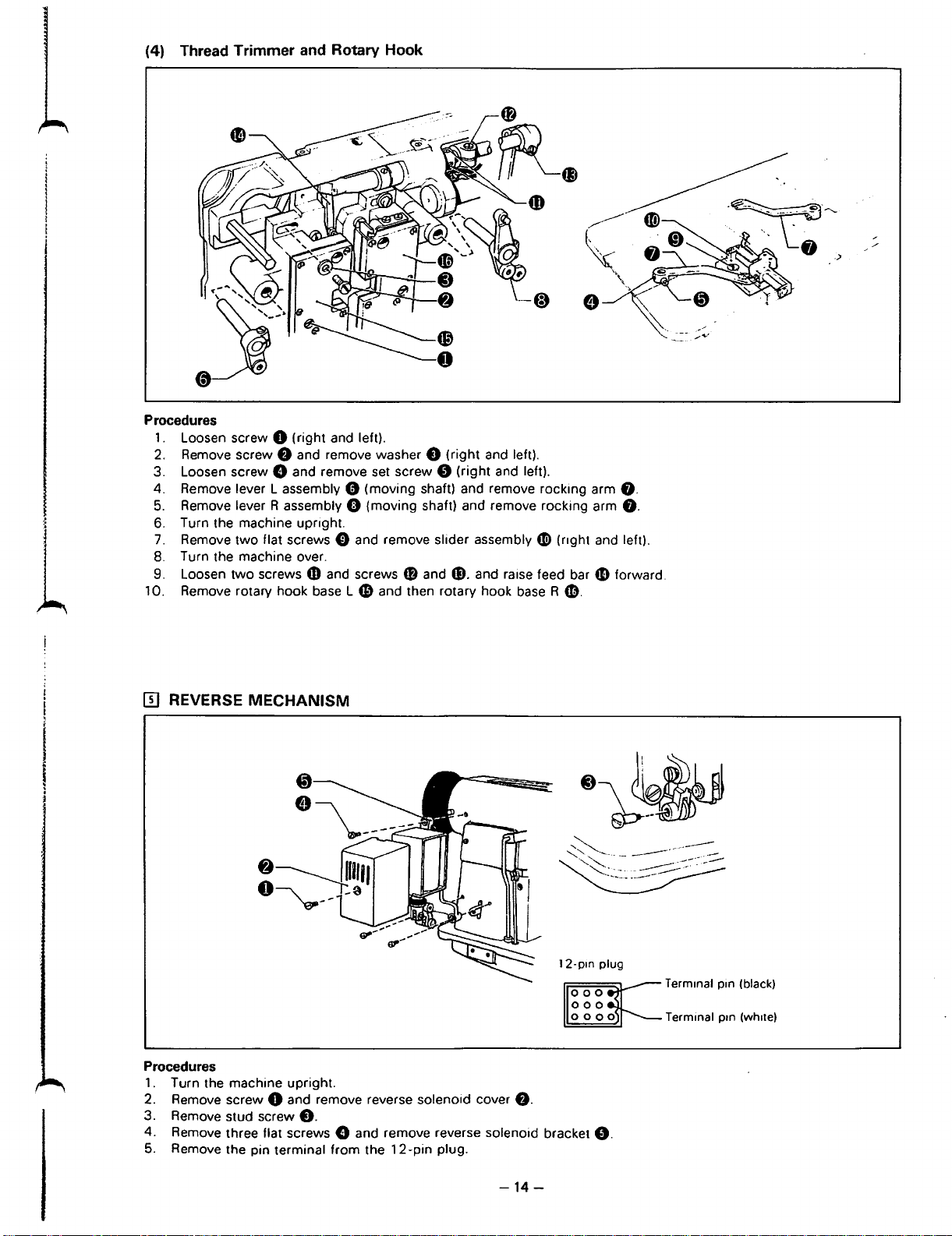
(4) Thread Trimmer and Rotary Hook
Procedures
1.
Loosen screw 0 (right and left).
2.
Remove screw
3. Loosen screw 8 and remove set screw 8 (right and left).
4. Remove lever L assembly 0 (moving shaft) and remove rocking arm
5.
Remove lever R assembly 0 (moving shaft) and remove rocking arm
6. Turn the machine upright.
7.
Remove two flat screws 0 and remove slider assembly
8.
Turn the machine over.
9. Loosen two screws
10. Remove rotary hook
f)
and remove washer 0 (right and left).
4D
and screws
baseL
fD
and ~-and raise feed bar G) forward.
49
and then rotary hook
4D
(nght and left).
base
R
CD.
8.
f).
[[]
REVERSE MECHANISM
12-pm
Procedures
1.
Turn the machine upright.
2. Remove screw
3. Remove stud screw
4. Remove three flat screws 8 and remove reverse solenoid bracket
5.
Remove the pin terminal from the
0 and remove reverse solenoid cover
0.
12-pin
plug.
f).
plug
8.
Term1nal
Terminal
pm
pm
(black)
(wh1te)
-14-
Page 18
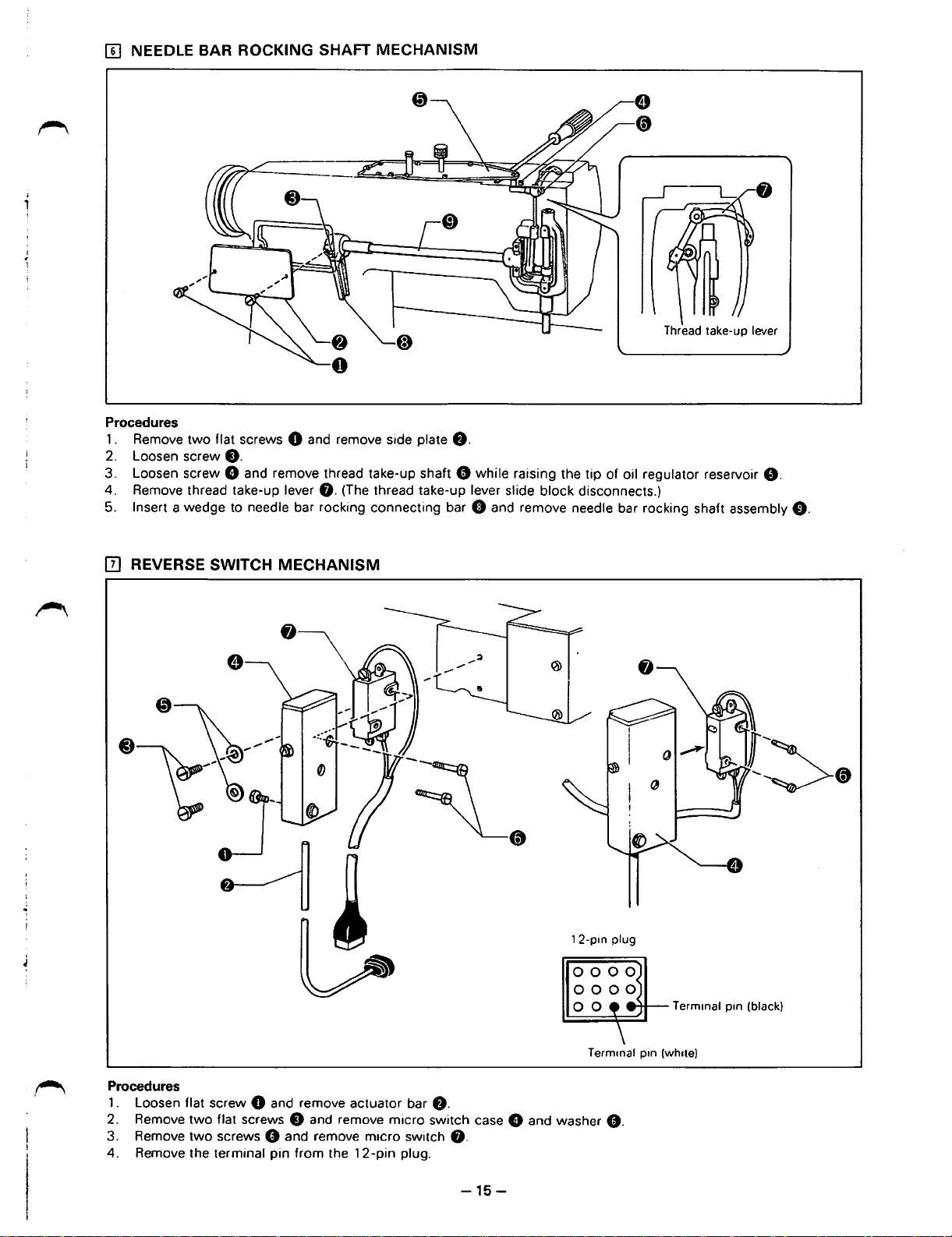
[II
NEEDLE BAR ROCKING SHAFT
Procedures
1. Remove
2. Loosen screw
3. Loosen screw 8 and remove thread take-up shaft 0 while raising the tip of oil regulator reservoir
4. Remove thread take-up lever
Insert a wedge to needle bar rocking connecting bar 0 and remove needle bar rocking shaft assembly
5.
two
flat screws 8 and remove side plate
f).
8.
MECHANISM
Thread take-up lever
f).
(The thread take-up lever slide block disconnects.)
0.
0.
[I] REVERSE SWITCH
MECHANISM
Term1nal pin (black)
Procedures
1 . Loosen flat screw 8 and remove actuator bar
2. Remove
3. Remove two screws 0 and remove micro switch
4. Remove the terminal pin from the
two
flat screws 8 and remove micro switch case 8 and washer
12-pin
f).
f).
plug.
-15-
T ermmal pin
0.
(wh1te)
Page 19
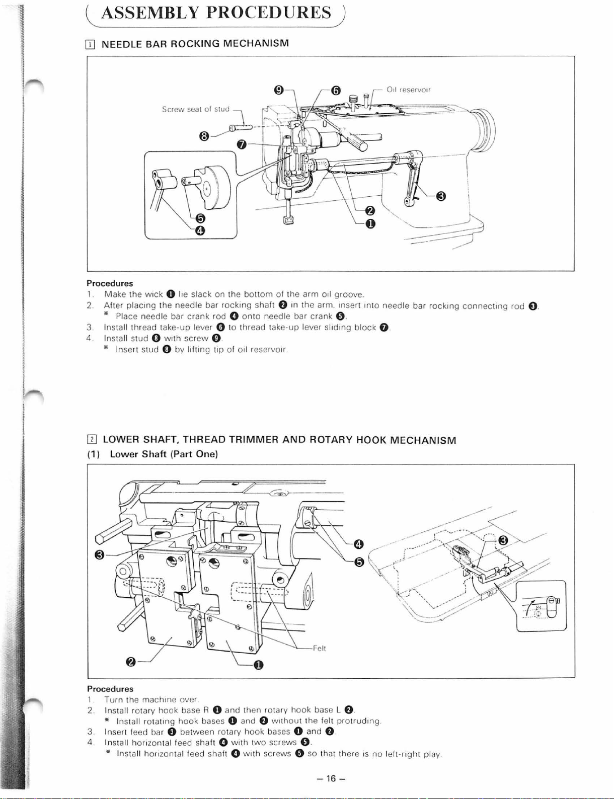
l ASSEMBLY PROCEDURES)
OJ
NEEDLE BAR
Procedures
1 Make
2
the
Alter
placmg
• Place needle bar
3 Install thread take-up lever 0 to thread take-
4. Install
stud 0 wnh
• Insert stud 0 by l1ftmg
ROCKING
w1ck
0 he slack
the needle bar
crank
screw
MECHANISM
on
the
bottom
rockmg
rod 0 onto
shaft
0 .
t1p
of
oil
reservo1r
of
the
f)
m
the
needle bar
up
arm
oil groove.
arm. 1nsert mto needle bar
crank
0 .
lever slidmg
block
0 .
rockmg
connectmg
rod
O.
ITJ
LOWER SHAFT,
(1)
Lower
Proc
edu
1. Turn the
2.
Install rotary
• Install ro t
3 Insert feed bar 0 between rotary
4 Install honzontal teed
• Install
Shaft
res
machme
homon
(Part
hook
at1ng
tal feed sha
THREAD
One)
over
base R 0
hook
and
bases 0
shalt 0 w1th two
lt 0 w1t
TRIMMER
then rotary
and
f)
w1thout t
hook
bases 0
screws 0 .
h screws 0
AND
hook
ROTARY
base L
he
felt prot
and
f)
so
that there 1s
HOOK
f)
.
rudmg
MECHANISM
.
no
lelt-nght
play.
-16-
Page 20
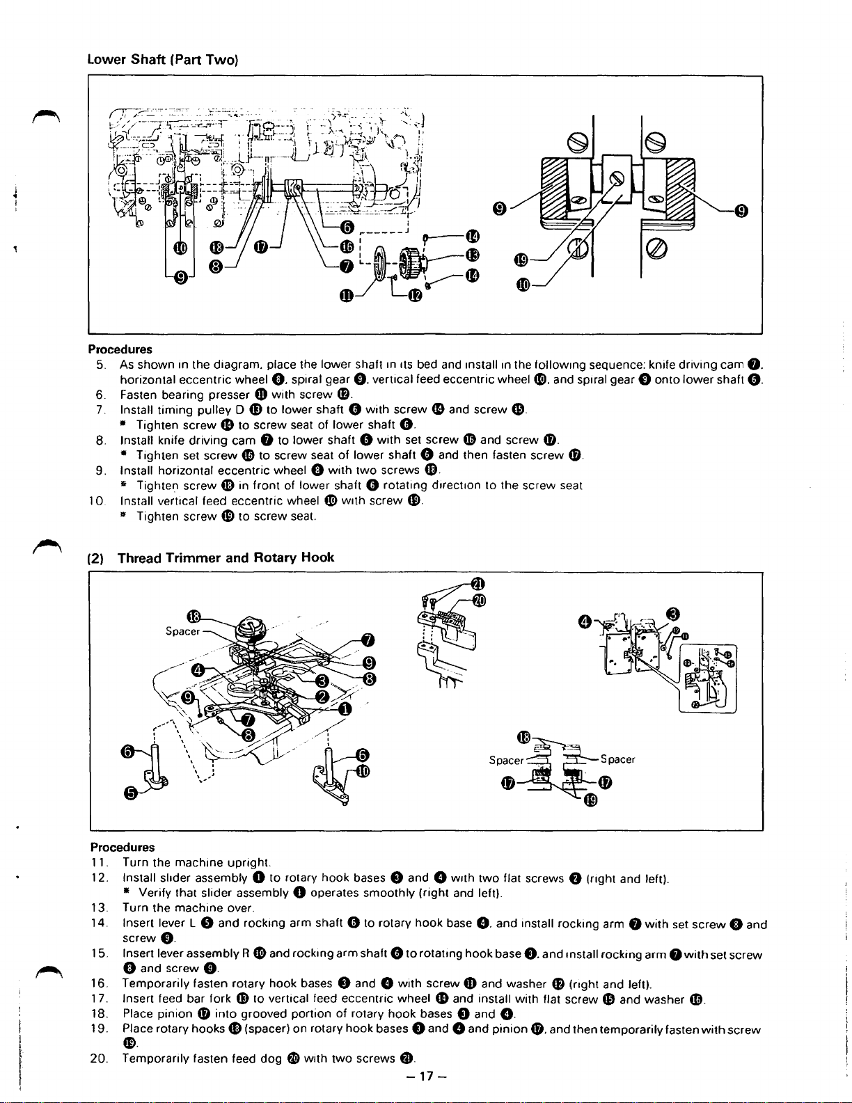
Lower Shaft (Part Two)
Procedures
5.
As
shown
1n
the diagram. place the lower shaft m
horizontal eccentric wheel
6. Fasten bearing presser
7.
Install
timing
pulley 0
• Tighten screw
8.
Install knife driving cam
• Tighten set screw ~ to screw seat
9. Install horizontal eccentric wheel 0
• Tighten screw
1 0. Install vertical feed eccentric wheel
• Tighten screw
G)
41
CB
Cl).
spiral gear
4D
with screw
f»
to lower shaft 0 with screw
to screw seat of lower shaft O.
f)
to lower shaft 0
in front of lower shaft 0 rotating
to screw seat.
1ts
bed and 1nstall
C).
vertical feed eccentric wheel«!). and Spiral gear
1n
the followmg sequence: knife driving cam
0.
G)
and
screw$.
with
set screw
of
lower shaft 0 and then fasten screw 0).
with
two
screws
«!>
w1th
screw
CB.
Cl).
d1rect1on
4D
and screw 0).
to the screw seat
C)
onto
lower shaft
f).
0.
~
(2) Thread Trimmer
Procedures
11
.
Turn the machine upright.
12.
Install slider assembly 0 to rotary hook bases e and 8 With
• Verify that slider assembly 0 operates smoothly (right and left).
13.
Turn the machine over.
14.
Insert lever L 0 and rockmg arm shaft 0 to rotary hook base
0.
screw
15.
Insert lever assembly R «!)and rockmg arm shaft 0
0 and screw
16.
Temporarily fasten rotary hook bases 8 and 8
17.
Insert feed bar fork
18.
Place pinion
19.
Place rotary hooks G) (spacer) on rotary hook bases 8 and 8 and
0)
and
f).
G)
into
grooved portion
Rotary Hook
to
rotatmg hook base
with
to vertical feed eccentric wheel
of
rotary hook bases 8 and
fD
spacen~
fJ)
two
flat screws • (nght and left).
8.
and install rockmg arm
screw 0 and washer 0 (nght and left).
G)
and install with flat screw
0.
pinion
-
..
spacer
~
Cfj
f)
f)
8.
and mstall rocking arm
41
and washer
0). and then temporarily fasten
with
set
f)
screw
with
~.
with
0 and
set screw
screw
••
Temporarily fasten feed
20.
dog
~with
two
screws
f».
-17-
Page 21
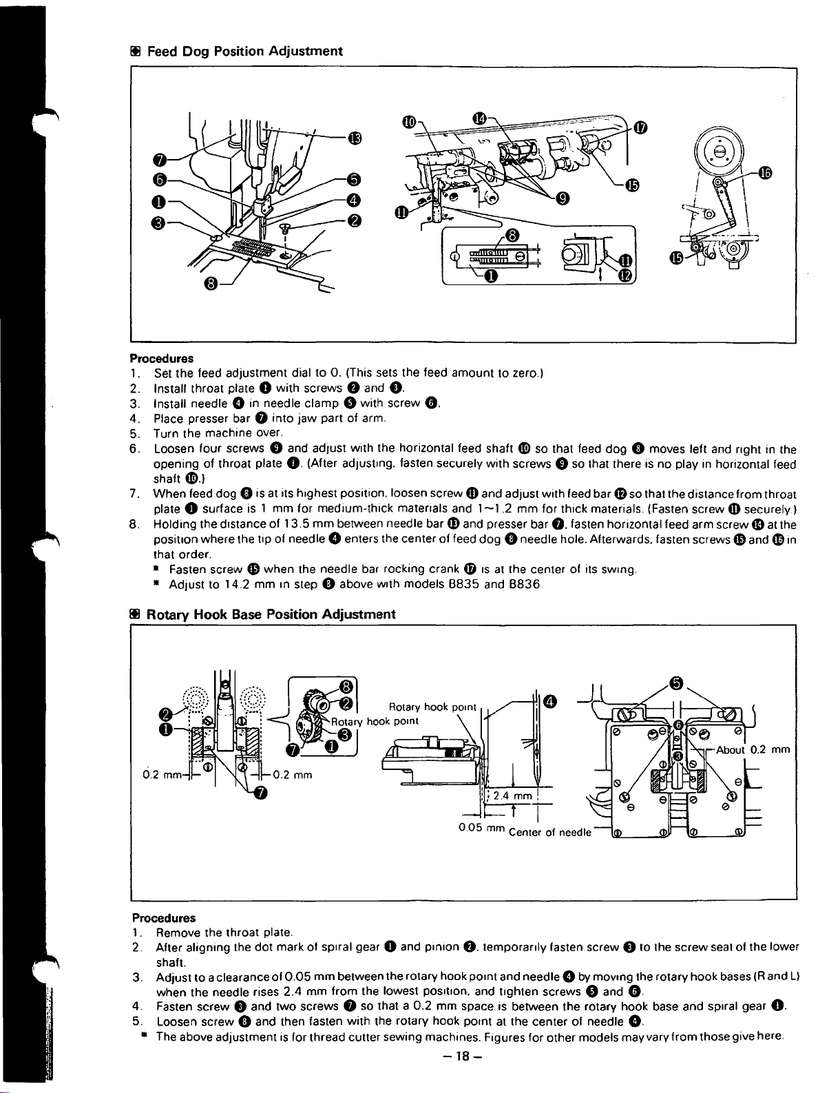
Ill
Feed
Dog Position Adjustment
Procedures
1. Set the feed adjustment dial to 0. (This sets the feed amount to zero.)
Install throat plate 0 with screws 8 and
2.
3. Install needle Gin needle clamp 0 with screw
4. Place presser bar 8
5. Turn the machine over.
6. Loosen four screws
opening of throat plate
tii).)
shaft
7. When feed dog 0 is at its highest position. loosen screw
0 surface is 1 mm for medium-thick materials and
plate
8. Holding the distance of
posit1on where the tip of needle 0 enters the center of feed
that order.
• Fasten screw
Adjust to 14.2 mm m step 0 above
•
into
jaw
part of arm.
0 and adjust with the horizontal feed shaft
0.
(After adjusting. fasten securely with screws 0
13.5
mm
between needle
fl
when the needle bar rocking crank 0
8.
w1th
G.
bare
models
tii>
fD
and adjust with feed bar
1-1
.2
mm for thick materials. (Fasten screw
and presser bar
dog
0 needle hole. Afterwards. fasten screws
1s
at
the center of its swmg.
8835
and
8836.
so that feed dog 0 moves left and right in the
so
that there is no play in horizontal feed
48
so that the distance from throat
fD
securely.)
8.
fasten horizontal feed arm
screw.
CD
and
at the
4D
in
Ill Rotary Hook
Procedures
1 . Remove the throat plate.
2. After aligning the
shaft.
3. Adjust
when the needle rises
4. Fasten screw 8 and two screws 8 so that a
5. Loosen screw 0 and then fasten with the rotary hook point
• The above adjustment
Base
to
a clearance
Position Adjustment
dot
mark of
of
is
sp1ral
gear 0 and pinion
0.05
mm between the rotary hook pomt and needle 0
2.4
mm from the lowest positiOn. and tighten screws 0 and
0.2
for thread cutter sewing machines. Figures for other models may vary from those give here.
8.
mm space is between the rotary hook base and spiral gear
-18-
temporanly fasten screw 8 to the screw seat of the lower
by
movmg the rotary hook bases (Rand
L)
0.
O.
at
the center of needle
8.
Page 22
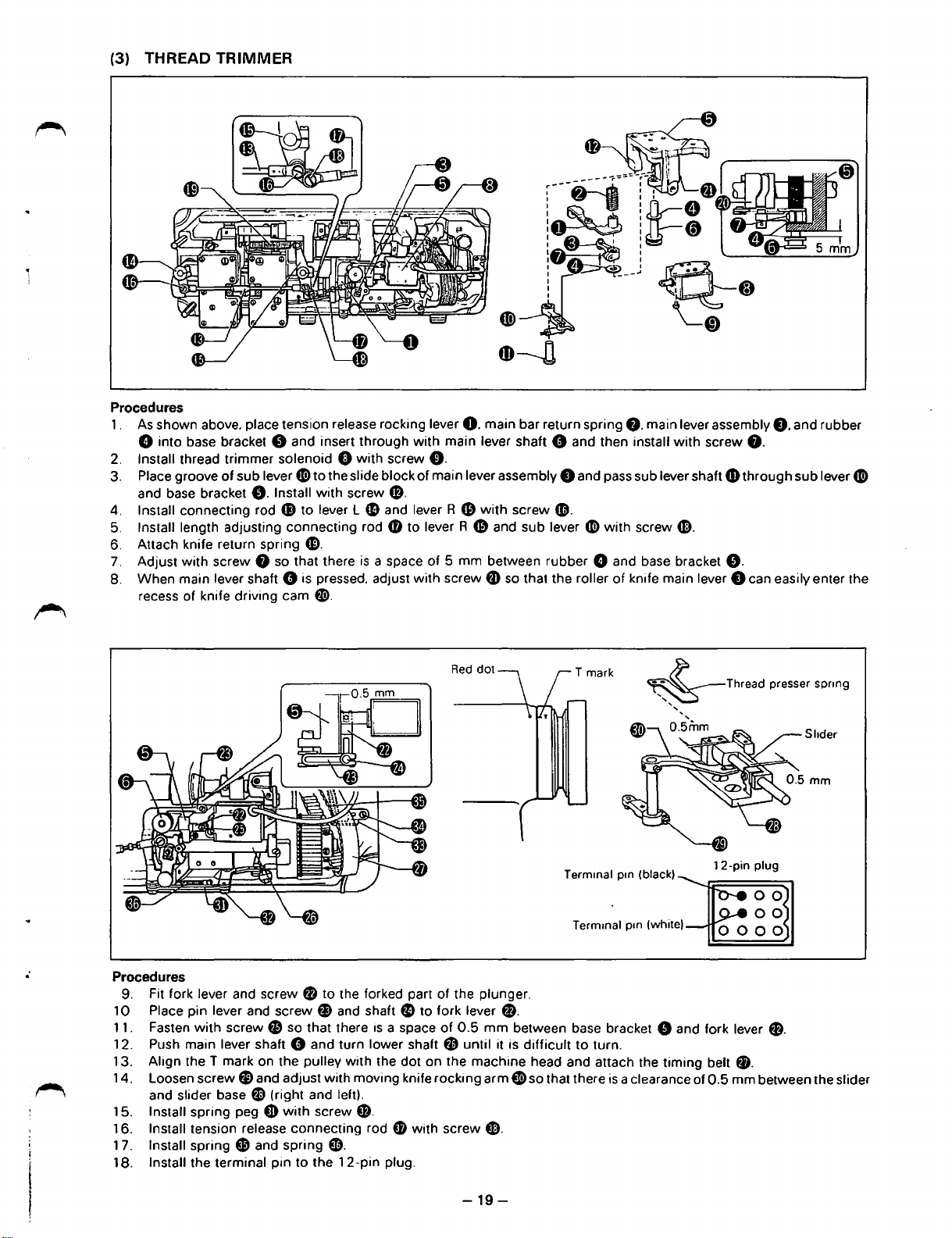
(3)
THREAD TRIMMER
~!l
~
Procedures
1 .
As
shown above. place tension release rocking lever
8 into base bracket 8 and insert through
2.
Install thread trimmer solenoid 8 with screw
3. Place groove
and base bracket
4. Install connecting rod G)
5. Install length adjusting connecting rod
6. Attach knife return spring
7.
Adjust
8. When main lever shaft 0 is pressed. adjust with screw
recess of knife driving cam
of
sub lever G) to the slide block of main lever assembly 8 and pass sub lever shaft
0.
Install
with
screw 8 so that there
to
G).
e.
with
lever l
screw
CD
is
with
$.
and lever R
4J)
to lever R
a space of 5 mm between rubber 8 and base bracket
0.
main lever shaft 0 and then install
0.
CD
main bar return spring
with
screw
4D.
CD
and sub lever 0 with screw
tD
so
that the roller
of
8.
main lever assembly
with
screw
8.
and rubber
8.
CD
through sub lever G)
CD.
8.
knife main lever 8 can easily enter the
..
Red
dot
·
Procedures
9. Fit fork lever and screw 0 to the forked part of the plunger.
0 Place pin lever and screw
1
1 1 . Fasten
12. Push main lever shaft 0 and turn lower shaft
13. Align the T mark on the
14.
15.
16. Install tension release connecting rod G with screw
1
7.
18. Install the terminal pin
with
screw
f1'
loosen
Install spring peg
Install spring G and spring (b.
screw
and slider base
tl
and adjust with moving knife rocking arm e so that there
8 (right and left).
fD
f»
and shaft
so that there
pulley with the dot on the machine head and attach the timing belt
with
screw G.
to
the
12-pin
is
a space
plug.
f)
to fork lever
of
fJ
0.
0.5
mm
until it is difficult
G).
between base bracket 8 and fork lever
T mark
Termmal
Termrnal pm (white)
to
turn.
o/
prn (black)
is
a clearance of
o.5mm
0.5
Thread presser spnng
Shder
12-pin
plug
00
0.
f).
mm between the slider
-19-
Page 23
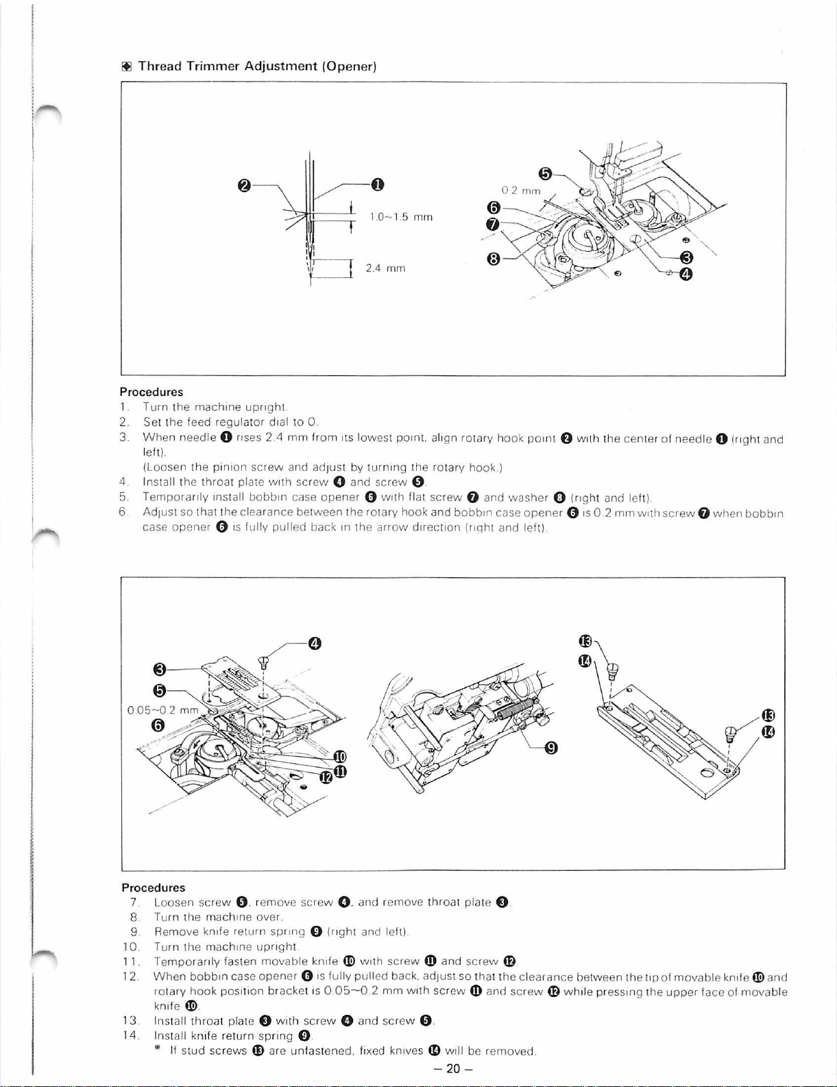
ltl
Thr
ead
Trimm
er
Adjustment (Op
ener)
Procedur
1. Turn
2. Set the feed regulat
3.
4
5.
6
es
th
e mach1ne
Wh
en
needle
left).
(L
oosen
th e
Insta
ll the
Temporarily
Adju
St
so
that the
case
opener 0 IS
0 nses 2.4 mm fr
pin1
on screw and
throat plate
1nstall bobb1n case
upnght.
or
d1al
to 0.
w1th screw
clearance bet
fully
pulled
~
om
adjus
0
1.0
2.4
1ts
low
t by t
urnmg
0 and
opener 0 wllh
ween
the
rotary
back
1n
the
-1.5
mm
est
pom
screw
arrow
mm
t.
al1gn
th e
9 .
flat
screw
hook
and
d1rect1on
rotary hook
rotary
hook
0 and
bobb1n case
(nqht and
pomt
f)
.)
washer 0 (nght
opene
r 0
left).
w
llh
1s
the
and left)
0 2
mm
center
wllh
of
needle 0
screw 0 when
(r1ght
bobbm
and
Procedur
7. Loosen
8. Turn
9 Remove
10. Turn t
1 1.
1 2
13 . In stall
1 4. Install knife re
es
sc
rew 9 . r
the mac
he
Temporan
Wh
en
rotary hook
kn1f
e W.
'" If stud sc rews
hme over.
kn1
fe return
machme upngh
ly fasten
bobb
1n
case
pOSitiOn
thr
oa t plate 0 w1th sc
turn
emove
opene
spn
CD
screw 0 . and remove t
spnng 0 (ngh
t
movable
bracket IS 0 .
are unfastened. f1xed
knife w Wi
r 0 IS fully
rew
ng
0 .
05-0 2 mm
0 and screw 9 .
t and left)
th
screw
pulled
back. adj
kn1ves
hro
at plate 0 .
m and
uSt
With screw
4D
will
- 20 -
screw
so
th at t
41)
and
be removed.
=
~
I
I
I
I
4D
he
clearance between the lip
SCrew
4!)
while
pressmg
of
movable knife W and
the
upper
face of
movab
le
Page 24
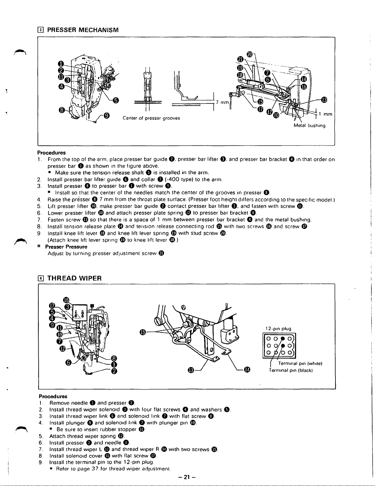
[I]
PRESSER MECHANISM
Center
of
presser grooves
Procedures
1.
From the top
presser bar
• Make sure the tens1on release shaft 0
2.
Install presser bar lifter gUide 0 and
3.
Install presser 0
• Install so that the center
4. Raise the presser 0 7
5.
Lift presser lifter
6.
Lower presser lifter (!) and attach presser plate spring
7.
Fasten screw
8. Install tension release plate
9 Install knee lift lever
(Attach knee lift lever
!11!
Presser Pressure
AdJUSt
of
the arm. place presser bar guide
0 as shown in the figure above.
collar 8 (-400
to
presser bar 0
of
mm
from the throat plate surface. (Presser foot he1ght d1ffers according to the
0.
make presser bar
G)
so that there
fB
CD
and knee lift lever spring
spr1ng
by turning presser adJustment screw
with
screw
the needles match the center of the grooves in presser
guide 8 contact
is
a space
and tension release
fD
to
of
knee lift lever
is
1 mm between presser bar bracket 8 and the metal bushmg.
0.
presser bar lifter
installed in the arm.
type) to the arm.
0.
presser bar lifter
fB
to
presser bar bracket
connecting
fD
with
stud screw
.:D.)
tD.
0.
and presser bar bracket 8
rod (D with
fli).
0.
and fasten
two
G.
screws
0.
with
4D
and screw
screw
Metal
bushmg
1n
that order on
spec1f1c
CD.
fD_
model.)
II)
~
THREAD
Procedures
1 . Remove needle 0 and presser
2.
Install thread
3.
Install thread
4. Install plunger 0 and soleno1d
• Be sure to insert rubber stopper &.
5.
Attach thread
6. Install presser
7.
Install thread
8. Install solenoid cover
9. Install the terminal pin to the
• Refer to page 3 7 for thread
WIPER
wiper
wiper
wiper
f)
and needle
wiper
f).
soleno1d 8
link 0 and solenoid link 8
spring
CD.
w1th
four
flat screws 8 and washers
l1nk
f)
With plunger pin (!).
0.
L
G)
and thread w1per R
4D
with flat screw
12-pm
wiper
plug.
adJUStment.
4D
0.
with
with
flat screw
two
screws
0.
(D.
-21-
8.
Page 25
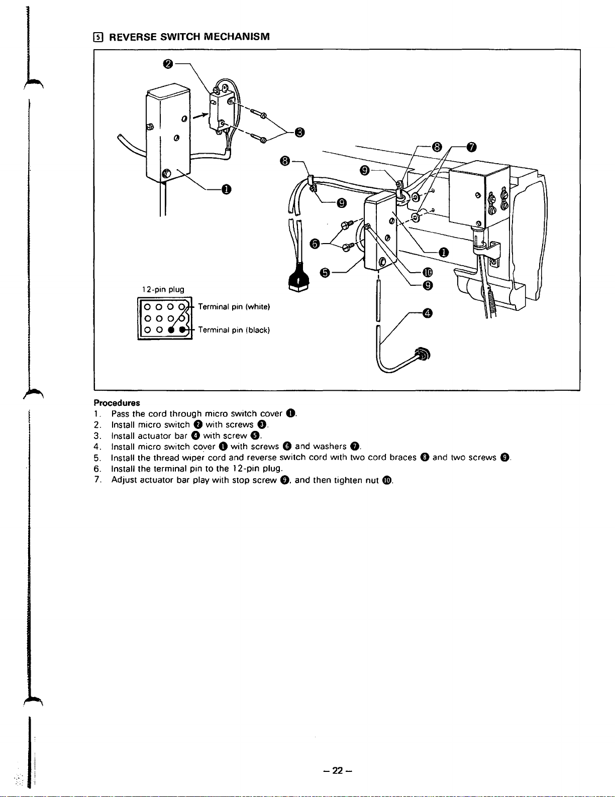
II]
REVERSE SWITCH
12-pin
MECHANISM
-0
plug
Terminal pin (white)
Procedures
1 .
Pass
the cord through micro switch cover
2. Install micro switch
3. Install actuator bar 0 with screw
4. Install micro switch cover 0 with screws 0 and washers
5. Install the thread
6. Install the terminal pin
7. Adjust actuator bar play with stop screw
f)
with screws
4:).
wipe~
cord and reverse switch cord with two cord braces 0 and two screws
to
the
12-pin
0.
plug.
0.
0.
and then tighten nut
8.
0.
~.
-22-
Page 26
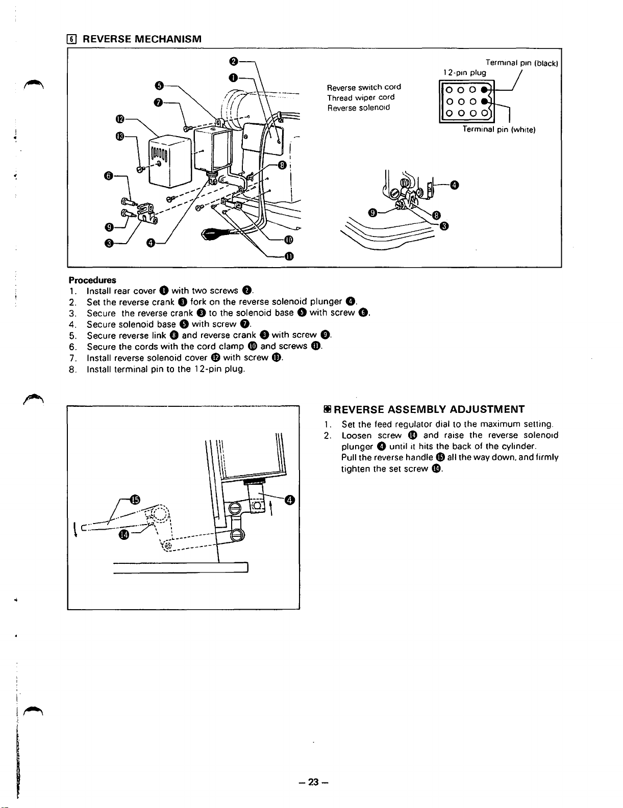
[!]
REVERSE MECHANISM
Procedures
1.
Install rear cover 0 with two screws
2.
Set the reverse crank 0 fork on the reverse solenoid plunger
3.
Secure the reverse crank 0 to the solenoid
4. Secure solenoid base 8 with screw
5.
Secure reverse link 0 and reverse crank 0 with screw
6. Secure the cords
7.
Install reverse solenoid cover
8. Install terminal pin to the 12-pin plug.
with
the cord clamp
f)
with
8.
f).
Gi)
and screws
screw$.
base 8 with
Reverse switch cord
Thread wiper cord
Reverse solenoid
8.
screw
f).
0.
CD.
12-pm
Termmal pm (black)
plug
Terminal
pin (white)
Ill REVERSE ASSEMBLY
1.
Set the feed regulator dial to the maximum setting.
2.
Loosen screw
plunger
Pull the reverse handle
tighten the
G until
set
fD
1t
screw
ADJUSTMENT
and raise the reverse soleno1d
hits the back of the cylinder.
49
all the way down. and firmly
e.
-23-
Page 27

[I] COVER
Procedures
1.
Install needle position detector 0 with two screws
2. Install synchronizer cover 0 with two screws G (and washers).
Install top cover 8 with screws 0 and
3.
4. Install face plate 0
5.
Install cover
6. Install slide plate R fl) and slide plate L
7.
Install slide plate F assembly & and stop with screw
with
4D
with two screws
stud screw 0 (and washer) screw
f).
f).
e.
8.
CD.
fD.
Page 28

(
sTANDARD
OJ
NEEDLE
AND
FEED
ADJ USTMENT (B831, B832, B835, B836, B882))
TIMING
(88
31 )
1. Remove
2.
T11t
the
machme
3.
Align
pos1110n 4 on
Hold the arm shaft
4.
t1mmg belt 0
5. R1ght the
!tl
Needle
and
the
needles.
on
machme
Feed
head. and remove
the
machme
f1rm
. align the
the
pulley
.
head and mstall the needles.
Timing
pulley
(Stand
the
arrow
ard
t1m1ng
with
on the
mod
belt 0 .
the red dot.
lower
be
el
8832, 8835,
lt 9 w
ith
the r
8882)
eference
line
on
the arm bed and
mount th
e
1 . Remove the needles.
2. Tilt the
3.
Turn the machme pull
4.
Whil
the arm
5. Return the
machme head back and
ey
e holding the
bed. and attach the
upp
mach
me head to its
er shaft so that
remov
until the ··A·
11mm
g belt 0
ongmal pOSi
e the
t1m1n
mark
1s
aligned w1th
11
won·t move. al
tion.
g belt 0 .
the red dot.
ign the
arrow
and
mstall the need les
on th e
low
er belt pulley 9
with
the referen
ce
line on
Page 29

Ill Thread Cutter Timing
(8832/
8835
with Thread Cutter)
~essthan
II
H
I~
@Thread Cutter Timing
1.
Remove the needles and tilt the head
2.
With main lever shaft 0 depressed. turn the machine pulley in its normal rotating direction unitl it gets hard to turn.
3. The T mark on the machine
(The
permissible deviation of the upper
pulley scale must
back.
be
in line with the red
and
lower shaft timing T mark from the center of the red
dot
on the machine head.
dot
is
2 mm.)
mm
@Upper and Lower
1 . Remove riming belt
2.
Turn the machine pulley until upper and lower shaft timing T mark
With
3.
4. Keep the machine
5.
main lever shaft 0 depressed. turn lower belt wheel
Recheck the upper and lower shaft timing T mark on the machine pulley.
•
Refer to the next page if the lower belt wheel
Shaft
Timing
O.
pulley and lower belt wheel
f)
in the arrow direction until it gets hard to turn.
f)
still. and put timing belt 0 on.
f)
is
improperly adjusted.
is
in lme with the red dot.
-26-
Page 30

rll
Lower Belt Wheel Position
'
-
(8832,
Reference screw hole
8835,
8837
Red
with. Thread Cutter)
mark
T mark
•
Deviation
±6°
-6"
1. Align the reference screw hole of timing belt wheel lower 0 with theV-groovescrewseatof lower shaft
to lower shaft
(The reference screw hole
2. Push main lever shaft
in its normal rotating direction until it gets hard to turn (where the movable knife begins to move).
3. Align the T mark with the red dot.
4. Hold the
(Put the belt around the upper wheel first.)
5.
Push main lever shaft
• Check that at this point the
• Allowable deviation:
• If deviation
Select one. retighten reference screw
0 with reference screw
is
red.)
8.
0 so the main lever roller enters the cutter drive cam groove. and turn timing belt wheel lower
pulley and timing belt wheel lower
8.
and turn the pulley to a
red
dot is in line
±2.0
mm
is
greater than 2.0 mm. remove the timing belt. Additional positions
8.
f)
in place. and mount the timing belt
point
where
it
is hard to turn.
with
the T mark.
remount the timing belt
as
in steps
0.
are
provided at +6°, +3°. and -6°.
2.
3.
and 4. and recheck.
Thread Cutting Timing
O.
and screw it
f)
rll
Thread cutting timing too early
• Needle thread may pull
• Thread cutter will not function properly.
• Top right thread catcher will not function properly with cotton threads.
out
Ill Thread cutting timing too late
• Needle and thread wiper will strike.
• Improper thread cutting.
-27-
of needle hole.
Page 31

[TI
ADJUSTMENT
OF NEEDLE BAR
TO
PRESSER BAR GAP (Models
:m-s
cry
II®
1.
Set the feed regulator dial to 0.
2.
The required gap between the needle bar 0 and
f)
is
presser bar
If necessary. adjust
1 ) Loosen screws 0 and
2) Turn the needle bar vibrat1ng crank 0 until the
reqUired gap (dimension
needle bar
3) Make sure the needle comes to the center of the
needle hole 0 in the feed dog
0 if necessary.)
dog
Turn the feed
position (so the needle enters the center of the needle
hole).
dimension
as
below.
0 and presser bar
dnvmg shaft 0 to adjuSt the feed dog 0
A.
G.
A)
IS
obtamed between the
f).
0.
(Adjust the feed
II
II
8831
·8832·8882
8835·8836
B831,
Model
B832,
8835,
8836,
A
13.5 mm
14.2
mm
8882)
Gap
too
D1mens1on
small
A
Ill When dimension A
• The feed dog will strike the needle plate when the feed
control dial is set to maximum.
•.
Skipped stitches and needle breakage will occur.
Ill When dimension A
• The feed dog will strike the needle plate when the feed
control dial is set to maximum.
• This will cause skipped stiches and needle breakage.
Gap
too
large
-28-
is
too large (feed dog):
is
too small:
Page 32

0 NEEDLE
• Be sure to check the
1 . Needle to rotary hook point
AND
ROTARY HOOK
pos1t1on
TIMING
detector adJustment (p.43) after the needle and rotary hook
gap
ADJUSTMENT
t1m1ng
1s
adJuSted.
Rotary hook pomt
1. Loosen the
needles and rotary-hook
2. Adjust the engagement
and the end face
•
Tighten the screws
• The needle
guard position
2.
Needle bar
screws@.®
of
the
©for
guard
on the rotary hook
when
the rotary hook
rise
and height
and©.
t1ps
are about
of
the spiral gear
sp1ral
gear
the
sp1ral
* Needle bar rise spectf1cat1ons vary
reference marks is 2.4 mm.
Needle
Needle guard
0-0.15
and move the rotary-hook base 0 to the
0.05
mm.
f)
by adjusting the clearance between the inner side
f)
to about
gear
is
to prevent needle to rotary hook
is
replaced.
w1th
d1fferent models. Use the followmg table to
0.2
f)
in such a way
mm
by moving the spiral gear
as
mm
not
to
change the contact.
right
or
left until the clearances between the
of
the rotary-hook base 0
f)
to the
nght
or
left.
point
contact. Be sure to readjust the needle
adJUSt
the
r1se.
The gap between
Models-8831 ·
Model
118-831
118-832
118-835
836
118-882
Needle bar nse should be set
•
When
•
machine
8832 · 8835 · 8836 · 8882
Application
Thin materials
Regular materials
Th1ck materials
Thin materials
Regular materials
Thick
materials
Regular materials
Regular
adjusting the walking bar feed regulator dial on model
matenals
pulley scale
Standard
SynthetiC threads 2.6
Synthetic threads 2 6
to
2.4 mm on machmes
with
the red dot.
2.4
2 4
2.4
2.4
2.4
2.4
mm
mm
mm
mm
mm
mm
mm
mm
R1se
Thread cutter Standard
----
--
-
2.4
-
2.4
2.4
--
with
wh1ch a thread cutter
B831.
Feed dial
Thread cutter
----
-------
mm
mm
mm
2
2
3
2
2
3 0
3
3
~
~
--------.___
--------
0
0
~
--
1s
used .
press the feed regulator button and align the
-29-
Page 33

Ill
Needle
Needle
bar
bar
down
rise
pos1110n
@
and
Wh
needle
en ra1sed
bar
height
Needle bar
2 4
mm
down
POS
iti
On
e
Needle bar
down
posH10n
(
Mod
el LT2-
B832-400A
8831 . 8832. 8882
( 1)
When
the needle bar e
with the bottom
line
.. a ..
of
the needle
(2)
When
the needle bar E) IS 2 4
•
aligned
needle
Loosen the
When
and
with
center
the rotary h
rot
ary
hook
ll I
[Mod
el LT2-
]
IS
In
ItS
lowest
pOSitOin.
edge
of the needle bar
bar with
the bott
thr
om
.
ee set screws 0 . and al1gn the rotary h
ook
pomt1s
po~nt
IS
the
bottom
mm
above liS lowes t
edge
of the need le bar bush1ng 0 .
aligned
1 - 1 .5
mm
with
.
B835-400A
the
bushmg
edge
the
needle center.
• Slide t
needle
he
]
POS
all t
iti
needle
he
On
clamp
1nt0 the needle
bar
0 Loosen the set
of the needle bar
POSitiOn.
needle pOSitiOn refer
Atth
1s lime. the rotary
ook
pomt
conf1rm that the
Rotary
way
reference I
screw
0 . and
bushmg
with
the needle
hook
me
0 .
spacer
po1nt
.. a ..
of
the
needle
align
the needle
ence
line
hook po1nt
center
between the top
~
•''
<I
~P.-,---'-
bar
must
pos1110n
.. b ..
Of
the needle bar
mus
t be al1gned w1th the
of
N"d
lo
t- t 5
be aligned
reference
the
needle eye
""'"
mm
IS
8835·8836
(
1)
Wh
en the needle bar E)
the bottom
(2)
Wh
en
the
aligned w1th the
needle cente r.
Loosen t
(3)
When the
hook
po~nt
Remove the set
po1nt and the
• One full revolut1on
edge
of
needle bar E)
bott
he
thr
ee set
rotary
hook
mus
t be 1 - 1 5
screw
top
of the needl e eye
IS Ill
liS l
owest pOSitiOn. the needle
the
needle bar bush1ng O.
IS
2.4
mm
above liS lowest
om edge
scre
ws
po~n
t
IS
0 . turn t
of set sc
of the
needle bar bush1ng 0
0.
and
align the rotary
aligned
mm.
w1th
he
needle
1S
rew 0 will
the needle
clampset
1 - 1 .5
ra1se
screw
mm
.
or lowe
POS
iti
POSitiOn.
hook
cen
needle
At
th1s
po1nt
ter. t
he
0 .
and
r the needle cla
On
reference line
pOSit
iOn
lime. the rotary
with
the
needle center.
space bet
adJUSt
ween
so that the
mp
.. a ..
Of the needle
reference line
hook
po1nt
the top
space betwe
app rox. 0.6
bar
IS
al1
.. b ..
of the ne
must
be
aligned
of the needle eye
en
the
mm
gned
edle bar
w1th the
and
rotary
rotary
with
hoo
IS
k
Page 34

[I] ROTARY HOOK TO NEEDLE PLATE GAP
0.6-0.9
mm
Ill Standard models
* The rotary hook 0
0 position
to
needle plate 8 gap should be
to
adjust the gap.
Ill Thread cutter models
* The rotary hook 0 to needle plate 8 gap
*
When
replacing the rotary hook. loosen screw
• Somet1mes
(I]
ROTARY HOOK TO BOBBIN CASE OPENER GAP
two
spacers 0 are required. Both should
is
set to 1
0.
and remove the rotary hook
0.6
to
0.9
mm. Loosen screw 0 and adjust the vertical rotary hook
.3
mm
with
a spacer
be
inserted under the rotary hook.
0.
0.
being careful not to lose the spacer
* The rotary hook 0 to bobb1n case opener 8 gap should
be 0.2 mm when the bobbin case opener is pulled all
the way m the direction of the arrow. Loosen screw 0
and move the bobbin
adjust.
r:ase
opener 8 right
or
O.
left to
1.
Needle
2. Needle bar rise. height
Rotary hook to needle plate gap
3.
4. Rotary hook to
•
Be
to
rotary hook point gap . . . . . . . . . . . .
....................
bobbm case opener gap
sure
to
readjust rotary hook lubrication after replacing the rotary hook.
•Improper
needle stitch1ng.
broken
•Improper
.
needle
• Excessive gap: Shuttle body may
•Insufficient
• Excessive gap: Loose stitches.
•I
nsuff1c1ent gap: Damage to shuttle body
adjustment may result in improper
needles.
adjustment may result in improper
stitching. skipped stitches. thread breakage.
gap: Improper stitch tightness
right
and left
skipped stitches. thread breakage.
right
and left
not
be
properly
positioned near the needle plate.
ing
improper
..
..
-----·---~·-·
st1tch tighten-
_____
___,
Page 35

[I]
PRESSER FOOT
HEIGHT
ADJUSTMENT
1. Loosen
(Remove the face plate on model 8835
Refer
2. The presser foot 9 bott om should be 7 mm from the needle plate top. Loosen screw 0 . and vertiCally adjust the presser
bar
(F1rmly re
•
• Use a presser foot
sc
rew 0 . open the face plate 0 . and
to
the table
below
for the requ1red presser foot he
0 to adjust the he1ght.
tigh
ten
screw
0 after adjustment
Be
careful
with
Refer
not
to
turn
presser bar 0
w1th
no
front
thm and standard matenals
to
page 6 7 for presser foot types.
Subclassif
~
Presser
• The presser bar lifter lever should be adjusted to 5
foot
Presser
Knee l1fter
bar
height .............
lifter
gap
to prevent
icati
on
Model
lever
ra1se
the presser bar
·8836
.)
1ght.
IS
completed
Sti
8831 I 88321 8835
tch
sk1pp1ng
7
mm
10
)
mm
l1
fter lever O.
or
thread cast-off at the start of sew1ng
Standard
8836 I 8882
8
mm
12
.7
mm
mm
for thm matenals.
when
Thread
B83
2-400A I B835-400A
7
10
Cutte
mm
mm
work1ng
r
900
A
-
32-
Page 36

[II
FEED DOG HEIGHT
ADJUSTMENT
•
0
1.
Turn the pulley and set the feed dog 0 to the up position.
2.
The feed dog 0 should be 1.0 mm above the needle plate. Loosen screw 8 and vertically adjust the feed bar 0 to
adjust the height.
11
The back
Frrmly tighen screw 8 after adjusting the height.
llllf
the feed dog
lll
If
the feed dog
7
of
the feed dog needle hole should be smooth to enable free thread passage.
is
too high: . . . •
is
too low: . . . . • Stitches will be shorter than indicated by the feed regulator dial.
The
feed dog will strrke the needle plate.
• Stitches will be longer than indicated by the feed regulator dial.
-33-
Page 37

[!]
TENSION RELEASE ADJUSTMENT
Tens
ion
discs are closed
0
Approx. 0.5 mm
Greater than 0.8 mm
1 • When the presser
1) Check the presser
2) Check that the thread tension disc 8 is open
0.
lever
3) Turn the tension release lever 0 to adjust the tension disc gap
2. During thread cutting
1) The tension release crank 0 to presser bar lifter 8 gap should be 1.5 mm when the tension release is not operating.
2) Loosen nut
Ill
Insufficient
• The thread will
Ill
Excessive
• Improper stitch tightening
• Loose stitches will appear
foot
foot
0.
remove screw
tenison
be
tension
is raised
height. Refer to page
held too tightly and will not pass smoothly
disc
disc
with
the presser bar
f).
and adjust
gap
gap
at
the corners
lifter
lever
32.
0.8
mm when the presser
with
the link
with
thread cutter sewing machines.
0.
8.
through
foot
is raised 7
the disc.
mm
with the presser bar lifter
-34-
Page 38

[I]
STITCH LENGTH
f)__,_
__
-
@)=::r-------~~-~
1 . Forward feed adjustment
(1) Set the feed regulator dial 0 to the maximum position.
(2)
Sew.
(3) Measure the stitch length.
ADJUSTMENT
_
~.
To increase stitch length
( 1 ) Loosen screw
(2) Tighten screw
To decrease stitch length
(
1)
Turn the feed regulator dial 0 all the way counterclockwise.
(2) Loosen screw
(3) Tighten screw
2.
Reverse feed sewing
*Reverse
3.
Aligning forward/reverse feed stitch lengths
( 1 ) Adjust the forward feed stitch length.
(2) Sew. Stop the machine with the needle below the top of the needle plate.
(3)
(4) Adjust the reverse feed stitch length by adjusting the position
feed stitch length
Drop
the reverse lever 8 (reverse feed switch) all the way down to sew in reverse.
stitch length
• Readjust the stopper 0 position when the forward feed stitch length
8.
and turn the feed regulator dial 0 counterclockwise.
8.
and turn the feed regulator dial 0 clockwise.
8.
and turn the feed regulator dial 0 clockwise.
8.
is
determined by the forward feed stitch length.
will decrease
as
the stopper 0 is raised.
of
the stopper 0 on the reverse lever
is
changed.
0.
Reverse feed
-35-
Page 39

[@]
REVERSE FEED SOLENOID
ADJUSTMENT
1 . Loosen screw
2. Turn the feed regulator dial
Raise
3.
4. Completely lower the reverse lever
5. Tighten screw
the reverse feed solenoid plunger
O.
0.
to
the maximum stitch length setting.
r
il
An
excessive gap between the soleno1d base and reverse feed solenoid
strength of the magnet and may prevent reverse sewing.
Ill Reverse switch adjustment
r--~----·
~
I
I
G.
f)
until it meets the back of the solenoid
1 . Loosen screw
it is easy to reach.
Firmly tighten the screw
2.
3. Loosen nut 8 and turn screw 8 to
pushbutton
pressed.
so
0.
plunger
0.
and posrtion the pushbutton
will decrease the
O.
that the switch
is
f)
where
adJuSt
activated when
the
0
-36-
Page 40

[ill THREAD WIPER ADJUSTMENT
--
-..-
About 0.3 mm
1.
Set the switch to the needle up stop pos1tion and the feed adjustment
Set the needle to the needle up stop position.
2.
3.
Loosen the
from the needle point when it
•
Make sure that thread wiper link B
4.
Pass
5.
Loosen the screws
threads
four
screws
f).
and raise
is
pressed
or
8 will not contact the presser bar .
the threads through the needles.
0 and move the thread wiper 0 to the right
with
its hooked end.
lower the solenoid 0 until the tip
with
your finger
as
d1al
to pos1tion 2.
of
the thread wiper 0 projects about 0.3 mm
shown.
or
left so that the thread wiper
Owill
positively hook the
\
6. Loosen the screws
presser set screw
• If the clearance
the thread
Also check that the needle set screws
wiper 0 as
f).
and raise
0 is about 1 mm when the thread wiper 0 returns to its ongmal position.
is
too little. the thread
close to the needles
Solenotd plunger
or
lower the stopper 0 until the clearance between the tip
wiper
0 may
not
be able to hook the threads depending on the kind
as
possible. provided that the threads will positively pass
will
not contact the thread wiper
0.
1
of
thread
More
Less
wiper
of
through
0 and the
thread. Set
the work.
-37-
Page 41

7.
The path
needle tip
The
Ill Step 3
If the
If the gap is
Ill Step 6
If the 1 mm gap is
Ill Step 7. above
If the
If the gap is
of
the thread wiper 0 tip is shown in the figure above.
to
thread
0.3
mm gap is
0.5
to
wiper 0 tip
too
too
small. thread wiping will not
too
great. the thread wiper 0 will strike the presser foot.
1 mm gap
too
is
small. the thread wiper 0 will strike the needle tip.
gap should be
great. the thread wiper 0 will strike the presser foot.
too
great. thread
0.5
to 1 .0 mm. Loosen screw 0
be
properly performed.
wiping
will not
be
properly performed.
to
adjust.
-38-
Page 42

(g)
SLIDER
1. Slider
Bobbin thread clamp spring
ADJUSTMENT
l
Lever
Connecting rod
1)
Remove the bobbin thread clamp spring.
2) The slider 0 to slider base 8 gap should
8.
the movable knife rocker arm
3) Loosen set screw
2.
Bobbin
thread clamp
0.
and adjust the
spring
(The slider 0 should not strike the slider base 8.)
forward/back
8
Movable knife return spring
be
0.3 to
0.5
mm when the movable knife 8 is worked back and forth with
position
•
• The bobbin thread clamp spring 0 should be installed
0.3-0.5
Bobbin thread
of
the movable knife rocker arm
If
the thread end is not clamped lightly on horizontal
rotary hook machines. stitch formation at the beginning
of sewing
spring 0
end.
directly below and slightly to the side
knife.
Note:
is
not possible. The bobbin thread clamp
is
provided on this machine to hold the thread
Be
careful th clamping area
clamp spring 0 does
or
feed dog.
clamp
not
8.
of
the bobbin thread
touch the rotary hook
mm
of
the movable
Ill Insufficient bobbin thread clamp spring tension
• Stitches will
be
skipped at the beginning of sewing when a heavy thread is replaced with a light thread.
Ill Excessive bobbin thread clamp spring tension
• Several stitches will be skipped at the beginning
of
sewing.
-39-
..
. j
I
I
Page 43

[ill MOVABLE
AND
FIXED KNIFE
ADJUSTMENT
© Removing the movable and fixed knives
! I
( 1) Remove the needles and raise t
(2) Remove the screws
(3)
Loose n the screw
Tilt th e head back.
(4)
(5)
Remove t
(6) Operate the osc1llat1ng
(7) Remove t
(8)
Remove the screws 0 and remove the f1xed
he
kmfe ret
he
screws 0 . and remove the movable
0 a
nd
remo
f)
. remove screw 0 and remove the n
urn
spn
ng
arm 0 until
he
pres
ser foot.
ve the cover 0 .
ee
dle plate.
0 . an d retu rn the head to Its ong1nal POSitiOn.
the screws 0 are
kn1fe
v1S1bl
kn1fe ().
~
.
e (
with movab
le kn1fe
on
nght
)
I
I
·'
:•
-40
-
Page 44

© Installing the movable and fixed knives
(1)
Turn the machine pulley by hand until the bobbin case openers are pulled all the way in the arrow direction.
(2) Temporarily fasten the movable knife
your finger from above.
(Securely tighten the screws 8 after the clearance between the tip
0 with the screws
0.05 - 0.2 mm.)
(3) Fasten the fixed knife
(4) Fasten the needle plate
(5) Fasten the cover 8 with the screws
(6) Tilt the head back and install the knife return spring
(7) Return the head to its origmal
(8) Install the needles m the needle clamp and lower the presser foot.
CD
to the needle plate with the screws
With
the screws e and
G.
8.
pos1t1on.
8.
and operate the movable knife 0 while pressing it with
of
the movable knife and the holder bracket is set to
0.
(Note the fixed knife has right and
0.
wrong
sides.)
011
-·~.
whetstone
Be
sure the edge
clean and sharp.
uttmg part
C
A ragged edge
may result in
thread breakage
@ If the
•s
kn1ves
become blunt. sharpen the fixed
as
shown.
kn1fe
The movable
ordinary whetstone.
If it becomes blunt. replace it with a
0 cannot be sharpened with
new
one.
kn1ves
«!)
an
(II
Movable
\.
knife 0 to rotary hook contact
or
excessive knife to hook gap may result in improper thread cutting.
-41-
Page 45

[ill KNIFE
MAIN
LEVER ROLLER
1.
Install
2.
Check
3.
Press the
drivtng arm
•
Tighten
0
the
knife
that
the
ma~n
the
return
knife
ma1n
lever shaft 0 .
recess .
nut
on
the
spnng
lever
stopper
Damper
.
shaft
turn
the pulley. and
screw
0 to
0 so t
Auxtltary
screws
support
hat
turn
the
lever
f)
gap
stopper
screw
is 5 mm.
screw 0 so
w1ll
not loosen
Pm lever woth scr
/
e K
(Loosen
the
after
Kntfe
drtvmg
ntfe return
Otagram
screw 0 to
main
lever
the
adJuStment
ew
pan
tng part
(A)
of
adJUSt.)
roller
easily enters the
1s
kntfe
drtvtng
completed
cam
.
kn1
fe
[j]] KNIFE
* Knife
1.
When
Loo
sen
2. Be sure t
DRIVING
dr
iving lever
0
the
ma1n
screw
her
e is
LEVER
lever
shaft
0 to
adJ
no
play parallel to the shaft
ADJUSTMENT
0 tS at res
USt the knife dnv•ng leve r
0.5
mm
t.
the
kn1fe
dnv
1n the
ing lever
f)
pin
f)
to
movab
.
lever 0 and knife dn
le
knife
base
bracket 0 gap
ving
lever
should
be
0.5 mm.
f)
.
-42
-
Page 46

[!!]
POSITION DETECTOR ADJUSTMENT
Needle
down
stop
pos1t10n
1 . Thread cutter element
Set the thread cutter element 0
2.
Needle down stop position
Set the needle down stop element 8 to 2.5 on the position detector scale.
3.
Needle
Adjust the needle up stop element 0 so the red dot on the arm and the pulley mdex are aligned when the treadle
pressed to reverse.
[Adjustment]
Loosen screw
respectively.
up
stop position
(The
needle up stop element should
0.
and move the thread cutter element
to
0.5
on the position detector scale.
0.
needle
be
at approximately 8 on the positron detector scale.)
down
stop element
Needle
8.
up
slop
and needle up stop element
R~ex
pos01oon
--T 1 !""I
is
0.
[!ZJ
CORNER SEWING POSITION ADJUSTMENT
1 . Needle feed rocker
crank
adjustment
(8835·8836)
* Turn the center screw 0 in the fork
so the needle feed rocker crank 0 fits in the fork.
Tighten nut
•
the crank secure in the fork.
0 after the adjustment
of
the slide arm 8
is
completed to hold
Stiff needle feed rocker crank 0 operation will make the needle bar strff. too.
-43-
Page 47

2.
Push
lever position adjustment
0
Snap
rmg
* Push the shaft 8 m the d1rect1on
honzontal play. and
Be
sure the push lever 0 still operates smoothly.
t1ghten
screw
of
the
arrow
to
prevent
8 to the screw stop.
Excess1ve
•
together or
3.
Slide shaft adjustment
* Set
stop
slide shaft 0
honzontal play
e1ther
lever • to R on POSition
is
* Lever shaft arm e
slide shaft
0
IS
mdependently. It
0
even
with
the end
will
not
function
not
properly aligned
will
affect the
guide
of
properly. and lever shaft
stop
will
be hard
•.
Loosen
slide shaft
with
the end
lever
to
drive both
screw
support
of
pos1t1on.
Shde shaft
e and
8.
arm
slide shaft
and
will
result m
or
e1ther needle(s) if the
support
move
spring
support
bracket
lever shaft
and set collar adjUStment
8.
poor
operat1on
dr1ve
arm e right
of
both
needles
torque
is
too
great.
or
left so that the end
will
be diffiCUlt. if the.
of
Page 48

4.
Slide shaft support bracket adjustment
0
* Set the stop lever to the
f).
frame
Insert gUJdescrew 0
dot
through
on
the posrtron
the oval hole
o.
Tighten stop
Improper
*
needle bar assembly
5.
Stop lever arm spring pressure adjustment
screw
0.
adJUStment may damage the slrde block tab and release prn end. resultrng
gUJde.
rn
shde shaft
Align
the left end
support
S prrng pressure
collar posrtron at stop
lever posrtron A
of
sir
bracket
de block 0 wrth the left srde
0.
and screw the set
rn
control
screwtrghtly
damage to the release prn and
of
the needle bar
rnto collar
*
Spring
pressure is properly adjusted
the L and R positions.
*
Screw
the
4D
is set
Spring pressure should be equal at both
•
If the stop lever 0
•
collar 0 tight
to
the L or R position.
at the
will
not
rf
the
point
where
stop at the dot.
stop
lever 0 stops at the center
the
stop
lever
arm
spring 0 lightly
positions
readjust
L and
the stop lever arm
R.
Sprrng pressure
collar
position at stop
lever posrtion L
dot
when
the push lever 8 is released from
touches the col:ar 8
spring
pressure .
control
when
the
stop
lever
Page 49

6.
Needle bar stop adjustment
* Set the needle bar 0
*
The
gap between the needle bar top and needle bar stop 0 bottom should be approx.
0
to
adjust.
*
Presser
foot height
to
the up position.
(8835-900)
0.5
mm. Turn the needle bar stop
1.
The presser foot 8 should
2.
Loosen screw 8 and vertically adjust the cylinder bracket 0 to adjust.
(Firmly retighten the scew
be
raised 7 mm above the needle plate by the presser bar lifter cylinder
8 after the adjustment is completed.)
-46-
0.
Page 50

[!!]
TIMING
BELT REPLACEMENT
Ill Removing the timing belt
(1)
(2)
(3)
Remove
Remove
Remove
two
screws 8 and the machine pulley.
timing
belt 8
timing
belt 8
r~
from
the
as
shown above.
I
I
timing
belt wheel
lower
8.
Ill
F1tt1ng
the
t1m1ng
belt on
( 1) Install
(2)
(3) Refer to page 50. 0 needle and feed
•
t1m1ng
belt 0
Fit the machine pulley onto the uppar shaft. and fasten
operating
Mount
direct1on
the sew1ng mach1ne pulley so there
1n
the arm open1ng. and place belt 0 around the
of
the machme.
w1th
the arm·s screw
t1m1ng
It
s~at.)
adjustment.
1s
no hor1zontal play
with
screws
e.
1n
the arm shaft.
t1m1ng
belt wheel upper.
(Align the front screw.
as
VIewed
In
the
-47-
Page 51

"'
U1SASSEMHLY
*
The
disassembly procedure descr1bed
procedure
OJ
COVER
for
model
LS
PHUCEUUH.ES
2-883
2 for d1sassembly
)
below
IS based on the standard version
of
the lower shaft and th read
[8837·8838
of
cutter
]
model
LS2-8837
assembly.
. Refer to the
Model LT2-B838
l
l'
j
Loosen
1.
2.
Remove the seven set screws 0 .
on
Remove bed slides L 0 and R 0 . (On
3.
Loosen set
4.
Remove
5.
Remove set
6.
(Removal
Loosen set
7.
Loosen set
8.
Replace
•
the
thumb
top
screw 0 . remove step screw
cover
0
.)
screw
CD
. and the needle
screw
4D
and needle plate
screw
G)
and
the
will
be easier if the vibrat1ng presser f
screw
4»
. and remove the l1ftmg presser f
screw
G)
and remove the needle guard
w1th
parts for a
two
f)
and washer 0 . and remove the face plate 0 .
top
cover
0 and
top
cover gasket
8838.
remove the set scr
4!)
.
4I)
.
vibr
ating presser foot
needle mach1ne on model
~
oot ~ 1s
oot
suppo
-
first
4D
rt W.
8838
ew
ra1sed
(leave
f)
. (Remove with the thread take-up cover
and remove bed slide F
w1th
the presser foot
the
thread
cutter
and thread cutter gu1de plate on .)
l1fte
fiD
r leve
.)
r)
1n
place
- 48 -
Page 52

III
TENSION RELEASE
1 .
Remove set screw
2.
Loosen set screw
3.
Remove set screw
Refer
to
the above diagram
LEVER
0.
and remove the triple
0.
and
remove the thread take-up spring regulator 0 and tension release lever rod
8.
and remove the thread take-up spring stopper
for
tension release lever disassembly.
eye
thread guide
0.
0.
8.
~
[!]
PRESSER FOOT
AND
WALKING
BAR
[1] PRESSER FOOT 0
1.
Loosen screw 0 and remove the knee lifter roller bracket
2.
Remove cotter pin
3. Remove stud screw
4. Remove stud screw
5.
Loosen the pressure regulating
6.
Remove presser bar lifter guide
• Disassemble the presser foot assembly after disassembling the walking bar assembly.
0.
and remove knee lifter complying bar
8.
and remove the knee lifter connecting rod
8.
and remove knee lifter lever spring 0 and knee lifter lever
thumb
screw (!). remove screw
Cl).
0.
G.
8.
G).
and remove the presser bar flat spring
8.
8.
-49-
Page 53

r~
1
!
I
!
I
I
I
I
.,
[2]
WALKING
BAR
ASSEMBLY
!
i
I
:)
A
Remove the
1.
(Remove the face plate thumb screw if one is present)
Remove the two screws
2.
Turn the nut on the bell crank roller 0 with a wrench and remove the roller
3.
Remove the bell crank
4.
Remove the bell crank link
5.
Remove the wick and remove the walking bar presser foot link
6.
7.
Remove the lifting presser foot adjustment
walking presser bar
Loosen screw
8.
Remove wing
9.
Loosen screw
10.
[1] PRESSER FOOT 8
two
screws
0.
and remove the feed lifting rocker shaft
8.
and remove the washer 8 and the lifting presser
8.
0.
CD.
41.
nut
8.
lock washer
Cl).
and walking bar eccentric crank
CD.
screw(!).
spring washer
0.
walking presser bar presser
48.
and hinge screw
fD.
t
8.
Gl).
foot
guide
0.
0.
0.
walking presser spring fl. and
I
__
~.---
1 . Remove the cap
2.
Loosen the screw 8 of the presser bar guide bracket
presser bar guide
3. Remove the presser bar guide
4. Remove the tension release lever 0 and thread tension release
0.
8.
and then remove the presser bar
8.
presser bar lifter
8.
the screw
0.
G.
and presser bar guide clamp
J
8ofthe
slide(!)
presser bar lifter
together
with
G.
and
thescrewf)ofthe
8.
the presser bar guide bracket
8.
Page 54

[D NEEDLE BAR
AND
NEEDLE
THREAD
TAKE-UP
41)
fi)
@
0
\
~
1. Remove the
2. Remove
3 Loosen
4. Remove the needle bar frame assembly 0 .
(The needle bar 0 . needle bar clamp
5. Loosen sc
(The w
6. Remove the thread take-up
7 Remove the thr ead take-up slide
(I]
FEED
two
screws 0 . and remove the needle bar frame stop
screw
0 . and rem ove
screw
0 . and remove t
rew
CF)
and remove the
1ck
will
come out
ASSEMBLY
th
e felt 0 and felt bracket 0 .
he
needle bar frame
thr
w1th
the thread take-up
4I)
.
~
-
~
-
and needle bar frame slide
ead take-up
and remove the needle bar crank r
(3
e
{;}@)
@(3
fii)
p1n
p1n
dnvmg
6)
.
6)
.)
shaft
f)
f)
.
block
.
4D
will come out.)
od
~
-
Remove the
1.
Remove st
2.
3. Tilt the mach1ne.
Loosen the three screws
4 .
• The p
Loosen
5.
Loosen the feed driving arm
6.
feed driving shaft
Loosen the feed driving
7.
eed dr
f
• The t
(Removal
• On
two
screws 0 . and remove the feed
op
screw 0 and the washer. and remove the
f)
1n
the
p1n10n
1n1
on
gear 0 and opener lmk 0
screw
~
-
and remove the fe ed bar
CD
screw
6)
. needle bar vibrating crank
m.
arm
CD
scr
ew
6)
. needle bar vibratmg crank
iving shaft m.
wo
set
col
lars
~
will
come off.
will
be
simp
lified if the feed driving
model 8838.
move the rotary hook base to remove the feed driving shaft
dog
f)
.
bobbm
gear 0 . and remove the rotary hook 0 .
will
also
come
liftmg
fork
41)
case
out.
.
G)
G)
arm
CF)
and need le bar vibrating crank
opener
screw~-
screw~-
0 .
and set
and set
40
collar
collar
G)
are opened
.
~
~
screw
screw
4»
. Remove the
4»
. Remove the
with
a wedge.)
Page 55

OJ
FEED ASSEMBLY
Q)---i
•
~~~:;;]
0
--==-tlti9l~r-
1.
Slide the collars 8 onto the feed driving shaft
0.
vibrating crank
Install the opener link
2.
• Align the spiral gear and pinion gear.
• Tighten the pinion gear screw against the screw stop of the rotary hook shaft.
Set the feed bar lifting fork 0 on the feed driving shaft
3.
4. Secure the feed dog
5.
Secure the needle plate
6. Tighten the set screw
Lightly tighten the set screws.
0.
rotary hook complete 0 and pinion gear 8 on the rotary hook base.
di)
with screw
48
with screw
I)
of
the collars 8 so the feed dog 0
CD.
G).
0.
and then slide them over the feed driving arm 8 and needle bar
0.
and lightly tighten the screw
is
centered in the needle plate
I
I
0.
48
hole.
m NEEDLE BAR
1.
Tilt the machine.
2.
Assemble the needle bar crank rod
3.
Pass
the thread take-up pin 0 and wick 0 through the thread take-up lever
with
0 so there
screw
0.
of
Tighten screw
• Hold the screw stop
4. Insert the needle bar frame driving shaft 0 in the needle bar frame assembly
5.
Secure
• The screw stop
• Slide the needle bar clamp
shown in the block
6.
Secure the needle bar frame stop
7.
Secure the thread take-up felt
8. Add oil to the wick
• Make sure the needle bar frame 8
is
of
the thread take-up pin 0 up while passing the wick through the take-up lever.
the needle bar frame driving shaft 0 should be facing
G).
41.
0.
thread take-up slide
no play in the thread take-up lever
G)
on the needle bar crank rod
48
with
screw
G).
G)
with
washer
is
4'1
and screw
not loose and that the machine works easily after assembly
8.
0.
G).
-52-
and thread take-up lever
8.
fit the needle bar frame assembly
8.
8.
and insert this assembly in the arm.
8.
up.
8.
and install
is
completed.
as
Page 56

OJ
WALKING BAR
[1] WALKING
e
-----,.:~____,~·
~--.<5--~--lllf
[2] PRESSER FOOT 0
BAR
AND
0
PRESSER FOOT
/
1.
Slide the walking presser bar 0 into the needle bar
frame.
2.
Mount
the walking presser bar spring
e.
presser bar presser
foot adjustment screw
• Turn the lifting presser
until the screw is flush with the arm top.
and tighten the lifting presser
e.
foot
f)
and upper feed
adjustment screw e in
------;
r
~
;::T·:.~
..
--
~ri5t~--
0
I
I
l
!
1.
Slide the presser bar 0 into the arm. and assemble the presser bar guide
presser bar guide bracket
2. Secure the vibrating presser foot 0 to the presser bar lifter 0 with screw
3. Tighten screw 0 so the distance from the bottom
0 is 1 mm.
guide
4. Adjust the vibrating presser foot
presser bar guide bracket
5.
Lift tne vibrating presser foot 0 10.5 mm
bar lifter lever
CD.
and tighten screw
,f))\
\:Mi
0
I
~
.
·.
:
\~rfr:
: \clJ.UI J
,
I
• • e
I I
I ..,
.....
J
L..--
.:e I
i :
e
9
I
rv··
\:--G
e.
of
the presser guide bushing 8 to the bottom
0 so the distance from the
top
e is 1 mm when the vibrating presser
with
the presser bar lifter
CD.
~
-.
10.5
mm
f).
presser bar lifter 8 spring fl. plate
0.
of
the presser bar
of
the presser bar bushing 0 to the
foot
is down.
CD.
press the presser bar lifter e against the presser
bottom
8.
of
and
the
-53-
Page 57

[1] WALKING BAR 8
Feed
dog
1.
Fit the walking bar rocker shaft 0 into the arm.
2. Fit the walking bar eccentric crank
Mount
3.
4. Fit the walking bar link 0 on the bell crank
(Fit the walking bar presser foot link 0 and bell crank 0 to three points: the bell crank link
bar. and presser bar lifter.)
5. Secure the
6. Secure the feed lifting rocker shaft
7.
Secure the lifting presser foot guide • with screw
8.
Fit
9. Replace the hinge screw
• Screw the wing nut
0. Secure the lifting presser foot
1
the bell crank
bell crank roller
the wick on the walking bar support link
f1)
on the walking bar shaft
&.
4D
tight
0 onto the walking bar shaft
0.
0.
4!i)
firmly
to
the bell crank
4D
with screw
0.
48.
0.
walking bar eccentric crank
at
the center
G)
with
screw
of
the walking bar eccentric crank 0 groove.
CD.
0.
0.
0.
and tighten the set screw
washer
fD.
lock washer
f)
so the crank
f1)
hole. walking bar presser
48.
and
wing
nut
G).
is
firm.
111
Lifting and Vibrating Presser Foot Vertical Timing Adjustment
1 . Loosen wing nut
2. Loosen bolt
3. Set the outer presser foot
4. Turn the machine pulley so that the thread take-up crank
outer presser foot
• Make sure there
• Adjust the lifting and vibrating presser feet to the same height.
( 1) Lower the lifting and vibrating presser feet
(2) Move the needle bar crank
G).
and retighten at the center of the walking bar eccentnc crank
f).
fB
and inner presser foot
f)
and inner presser foot
is
no play in the walking bar shaft
fB
on the thread take-up crank
G)
to the needle plate
f1
is
horizontal.
G)
are tight to the needle plate
0.
to
the needle plate.
f1)
to the right. and firmly tighten the set
-54-
0.
tJ.
as
shown in the figure above. Make sure the
tJ.
and then tighten bolt
f).
screw&.
Page 58

Ill N eedle Bar
Fram
e and Feed
Dog Posi
tion
Adjustment
B837
8838
0
0
1 Set the feed regulator
2 T1ghten the feed dog. needle plate. v1bratm g presser foot. and lifter presser foot
3 Secure the
4.
AdJUSt
AdJuSt
the adJustment
5
AdJuSt
needle 0
the needle bar v1brat1on crank 0 so the
the feed dn
the feed bar
d1al
to 0
w1th
screw
0
v1ng
arm 0 so the needle 0 enters t
1s
com
pleted.
«!>
so the feed
dog
gap
extends 1
between the presser bar 0 and
he m1dd
mm
le of the feed
beyond th e needle plate top. and then
dog.
walkmg
F1rmly
presser
t1gh
ten screws 8
t1gh
bar 0 IS
and Owhen
ten
screw
8.2 mm.
4D
-
55-
Page 59

Ill Needle
to
Rotary Hook Timing
Rotary hook pomt
0.05-Q.1
Needle
mm
IL~~Needle
TI1.5mm
J----r
2 .4
mm
1.
Remove the needle plate and feed dog. and set the feed dial
2.
The needle
position
3. Adjust the needle guard so the needle lightly contacts the needle guard after adjusting the gap.
Firmly tighten set screws
•
to
rotary hook point gap should
of
the rotary hook base 0
0.
f).
be
0.05
to
0.1
to
adjust the gap.
0 after the adjustment is completed .
Needle Bar Lift Stroke
* The rotary hook
position. Loosen the lower shaft gear 8 set screw 0 and shift the lower shaft gear 8 horizontally to adjust.
The screw stop on the rotary hook shaft prevents alignment using the
•
Tighten the set screw 0
•
point
should
be
aligned
of
the lower shaft gear 8
with
the needle center when the needle is raised
without
to
0.
mm. Loosen set screws
pinion
changing the screw stop used .
0.
gear.
f).
0.
and adjust the horizontal
2.4
mm
from
the
down
Needle Bar Height
* The needle hole edge to rotary hook
center. Loosen screw
Firmly retighten screw 0 after the adjustment is completed .
•
The rotary hook bushing determines the
•
gap is a fixed distance (1.2 mm).
0 and adjust the vertical needle bar position
point
gap should
he1ght
of
the rotary hook complete. The rotary hook complete to needle plate
Ill Bobbin Case Opener Adjustment
be
1.5 mm when the rotary hook point
to
adjust.
is
aligned
with
the needle
1 . Install the feed dog and needle plate.
2. Firmly tighten the bobbin case
3. The rotary hook 0 to bobbin case opener 0 gap should be
in the direction
the gap.
• Be sure to firmly retighten
of
the arrow. Loosen screw
opener
screw
0 in place with set screw
0.2
mm
f)
and adjust the horizontal position
f)
when the adjustment is completed.
-56-
f).
when
the
bobbin
case opener 0
of
the bobbin case opener 0
is
pulled all the way
to
adjust
Page 60

[2] PRESSER FOOT 8
1 . Tighten the presser foot adjustment screw 8 with the end of the presser plate spring 0 connected to the presser bar
guide bracket
2. Install the knee lifter lifting lever G and spring 8 with the screw
Hook the end
Install knee lifter lifting guide
3.
4. Secure the knee lifter connecting rod 0 with step screw
5.
Slide the knee lifter complying bar e
6. Secure the knee lifter roller bracket 8 to the knee lifter complying bar
8.
of
the knee lifter lifting lever spring 0
8.
onto
the knee lifter connecting rod
on
the spring peg.
0.
0.
e.
«!)with
and secure it
set screw
with
48.
the cotter
pin
CD.
I
Presser Foot Pressure Adjustment
* Adjust the presser foot pressure
[I] TENSION RELEASE
LEVER
with
presser foot adjustment screw
G).
1 . Tighten set screw 8 so both ends of the thread take-up spring stopper 0 are level.
2. Fit the tension release lever rod 8 in place.
3. Secure the
4. Secure the triple eye thread guide 0
• Assemble the upper tension control assembly G
upper
tension control assembly G
with
the set screw
with
set screw
0.
8.
as
shown in the figure above.
-57-
Page 61

I}]
COVER
1 . Secure the
2. Secure the face plate 8 with step screw
3. Install bed slides L 0 and R
(Install bed slide F 0 on model
top
cover gasket 0 and top cover
0.
8838.)
0.
f)
with
washer
set screw
0.
and
8.
thumb
screw
f).
-58-
Page 62

[0
NEEDLE
AND
FEED
TIMING
ADJUSTMENT
(standard)
R
ed
do1
Remove the
1.
Tilt the
2
Turn
3.
4.
Wnh
and
1nstall t1mmg bel t 0 .
5. Pull
the machme
Ill Thread
needle
machme
the mach1ne
the
upper
shah
cutter
timing
0
head
back
and remove
pulley
until
held sllll. align the
head back to
adjustment
t1m1ng
bell
0
pos1110n A 1S m line
arrow
1tS
or1gmal pos1t1on. and 1nstall
on
the t1mmg
w1th the red
dol.
belt
wheel lower 0 w1th
the
needle
T mark
the reference line
on
the arm bed.
Ill Thread
1. Remove
2.
3 The
@Upper and
1 Rem ove
2
3 Press
cutter
the
needle
Press the kn1fe
llrnmg
mark
from
the
center
lower
th
e t1mmg
Turn
the
pulley
the
kn1fe
timing
ma1n
shaft timing adjustment
and al1gn the t1mmg mark T
ma1n
Ton
of
and
lever
the
the
belt
lever
confirmation
lilt the mach1ne
shah
0 and
pulley
should
dot
0 .
shah
0 and
turn
be
turn
the
aligned
with
the
lower
pulley
1n the
w1th the red
the red
belt
dot
wheel
normal d1rect1
dot
on
pulley
turn
4
Hol
d the
ma1n
pulley
5. Recheck
,..
Refer to l
the
owe
ma1n
r belt
and the
pul
ley
pulley
lower
ummg
mark T alignment.
adJuStment
belt
wheel
on
page 2 7 1f the l
pulley 0 so
ower belt pulley
they
w111 not
- 59 -
the
0n unt1l
mach
ll
me head
0 m the d1rect1on
mo
ve. and
IS not
then
properly
1S
hard
Allowabl
of the
mount
pos
to
turn
e dev1allon
arrow
the
iti
oned
.
IS 2 mm
until
I!
IS
ummg belt
hard
to
0
Page 63

[I) FEED
DOG
ADJUSTMENT
IN
BACK
AND
FORTH
0
DIRECTIONS
15
mm
1. Turn the feed
2. Loosen screws 0 and
• After the adjustment. securely
3. Turn the mach1ne pulley
• Check
4.
Slowly
presser bar to
• If the needle does
( 1) Remove the rear cover. and loosen
(2)
Move
dog
f)
(3)
After the adjustment.
8.2
ad1ust1ng
the needle to be sure that
turn the machme pulley. and see If the needle falls exact ly m the
walkmg
needle bar
.
d1al
to
pos1t1on
f)
. and
adjust
lighten
until
the needle bar
1t
bar presser bar
not
fall exactly m the center
suppo
rt 0 little
tighten
by
screw
mm
!~\
0.
feed
dog
screws 0 and
IS
IS
not
bent. Or. replace
gap
1s
8.2 mm.)
screw
0 .
litt
le
unt
il the
0 securely.
f)
so that the
f)
up
m Its h1ghest poSitiOn
of
the needle hole m feed
tip
of
center
.
1t
with a new
the needle IS 1n l
!tl
,.
"
..
,,
,,
"
• The feed
• Sk1pped stitches. broken needles.
• I
of
1ts
needle hole will
needle
center of the needle hole
dog
f)
. adjuSt
1ne
with the center of the needle hole
be
as
11
1n
the follow1ng
shown
1n
feed
Excessive presser bar and
presser bar
the feed regulator
mprop
cutter
gap
dog
will
er thread tn
1s
used
stnke the needle plate
d1al
IS
set to
max
mmmg
when the
above.
dog
f)
manner
1n
walking
when
1mum.
thread
. (The
feed
Stnkes needle plate
gap
IS
lllSUffi
Cie
nl
Strikes needle pla te ''
''
gap
1s
excess1ve.
-
60-
Page 64

[I]
NEEDLE
1.
Clearance between needle and rotary hook point
AND
ROTARY HOOK
TIMING
ADJUSTMENT
Needle
touch lightly
Should
0.05-0.1
( 1) Loosen
between
(2) After adjusting the clearance between the needle and the rotary hook point. adjust the needle guard so that the needle
and the needle guard lightly touch each other.
• After the adjustment. securely tighten
The needle guard on the rotary hook is to prevent
•
Be
2.
Needle bar
sure
screws®.
0.05
to
readjust the rotary hook needle guard position when replacing the rotary hook.
rise
mm
®and
and 0.1 mm by moving rotary hook 8
and height
Rotary hook
©.
and adjust the clearance between the needle and the rotary hook point
pornt
screws®.®
to
right
or
left.
and
©.
the
needle from striking the rotary hook point.
to
somewhere
t
1
I
Rotary hook
point
\:
·.....----'-
Needle
1.5
mm
mm (8838)
2.2
(8837)
8
r
Needle bar rise
( 1) Turn the feed adjusting knob
(2) Loosen screws 8 for lower shaft spiral gear
hook point
lowest position.
• The rotary hook shaft has a screw seat.
• When tightening screws 8 for lower shaft spiral gear
Needle bar height
(1)
Turn the feed adjusting dial
(2) Loosen screws
the rotary hook point
the
•
After the adjustment. tighten screw 8 securely.
will be at the center line of the needle
8.
and move the needle bar up
to
needle.
to
to
1.5 mm
Model
118-837
1
18-838
position
so
position 0
(8837)
Application
Thick materials
Thick materials
0.
8.
and move lower shaft spiral gear 8 to the right
when
the above adjustment cannot
{8837)
or 2.2
or 4
or
down to adjust the clearance between the top
mm
or
left so that the rotary
the needle rises 2.4 mm with
be
8.
make sure that it is in line with the screw seat.
(8838).
(8838). when the rotary hook point is in line
Needle bar rise
Standard Thread cutter Standard
2.4
2.8
mm
mm
2.4
883
7.
2.8 mm
made with the pinion gear.
of
Feed
mm
0
0
with
8838
from its
the needle eye and
with
the center of
control
dial
Thread cutter
0
-61-
----------
-------
Page 65

IT]
CLEARANCE BETWEEN ROTARY HOOK
AND
NEEDLE PLATE
1.2
~
mm
* Rotary hook 0
hook
0 and needle plate
is
s~t
to the proper height by the rotary hook shaft bushing upper so that the clearance between rotary
f)
is
set
as
required (1.2 mm).
m CLEARANCE BETWEEN ROTARY HOOK
AND
BOBBIN CASE OPENER
* Adjust the clearance between rotary hook 0 and
bobbin case opener
bobbin case opener
direction) by
case opener
•
After the adjustment. tighten screw 8 securely.
f)
to
about
0.2
mm (when the
f)
has retracted fully in the arrow
loosening screw 8 and moving bobbin
f)
to
the right or left.
1. Needle to rotary hook point gap . • . . . . • . • . . . • Rough seams. skipped stitches. thread breakage. needle
breakage
Needle bar rise. height • • • . . . . • • • . • . . • . . . . . . • Rough seams. skipped stitches. thread breakage
2.
3. Rotary hook to
4. Rotary hook
•
Be
sure to readjust rotary hook lubrication when the rotary hook
needle plate gap . • • • . . . • . . . . • Too small: improper stitch tightening
to
bobbin case opener gap • • . . .
•Too
large: loose stitches. improper stitch tightening
•Too
small: shuttle body damage
-62-
is
replaced.
Page 66

[!]
PRESSER FOOT HEIGHT
1.
Raise
the outer presser foot 8 with the presser bar lifter lever
(Check that the distance from the needle plate 0 top to presser foot 8 bottom is 10.5 mm.)
2.
Insert a
3. Loosen screw
Firmly tighten screw 8 after adjustment
•
The presser bar flat spring will cause the vibrating presser foot to
Be
•
10.5
mm block underneath the vibrating presser foot
8.
and
careful not to turn the presser bar
ADJUSTMENT
0.
G.
raise or lower either the vibrating presser foot 8 or presser bar 0 to adjust.
is
completed.
drop
when the screw 8
0.
is
loosened.
I
i
I
~
I~
-63-
Page 67

[I]
FEED
DOG
HEIGHT
About 1
.0
ADJUSTMENT
mm
Turn the
lowest
2
Loosen
that feed
needle plate
•
F1rm
completed
machme
p0S1t1on
screw
ly ligh
pulley
f)
and
dog 0 will
ten
screw
unttl feed
ra1se
nse
f)
dog 0 drops
or
lower
about
1 0
after the adJUStment
th
e feed bar 0
mm
above the
to the
so
1s
ltl
When
ltl
When
the feed dog
the
feed dog is too
is
too high:
• The feed
• S
t1t
d1al
low
: . . . . . . . . • Stnches wtll
d1al
ches
dog
will stnke the ne
will
be lar
be
smaller
ger than
than spec1f1ed
edle
spec1
plate.
f1ed by
by
the feed r
the feed
egulato
regulator
r
- 64 -
Page 68

[!]
VIBRATING PRESSER FOOT
• When the needle descends. the lifting presser foot must touch the feed dog before the needle point reaches the feed
dog. When the
needle drops. the needle pomt must clear the feed
AND
LIFTING PRESSER FOOT
AND
NEEDLE
dog
before the lifting presser foot rises.
TIMING
ADJUSTMENT
When the needle goes down.
Needle
Feed
dog
1.
Loosen two screws
2. Adjust vibrating presser foot
wheel&.
• After the adjustment. tighten screws 8 securely.
8.
0.
lifting presser foot 0 and needle timing by turning by turning upper feed eccentric
When the needle goes up.
' I
' \
I '
'<,·-----.
·\
Needle
\
\
\
Feed
dog
l
t
III UPPER FEED
• This machine is assembled so that upper feed (needle feed) matches lower feed. (The reference line on the needle feed
rock crank matches the reference
the upper and lower feeds
• If
1.
Loosen nut
2. To decrease upper feed. move nut 8 toward feed driving shaft
3. To increase
• After the adjustment. tighten
ADJUSTMENT
do
not match. increase
0.
upper
feed. move nut 0 toward the
nut
line on the collar.)
0 securely.
or
decrease upper feed
8.
tip
of
needle feed rock crank
as
0.
follows
I '
I
I 1
I I
lcl
I I
I I
I I
I I
•
',
1,
'
' I '
to
match sewing conditions.
/
_,.
I
---
I
Upper feed
Lower
feed
-65-
Page 69

@]
VIBRATING f-kESSER
FOOT
AND
* The v1bratmg and l1ftmg presser feet move
* The vibratmg and l1ftmg presser feet
will
LIFTING PRESSER FOOT VERTICAL STROKE
up
and
down
111 alternate steps.
normally
r1se
the same d1stance.
I
I
~
:---
'
,'
\
-·
--
\
' '
'~,
---
\
J...
....
'
Feed dog
ADJUSTMENT
1. Loosen wmg
2. Loosen bolt 0 .
3. L
ower
4. Turn the mam pulley. St
•
M
ake
nut
both the
sure there is
v1bra11ng
0 and t1ghten the walk1ng bar eccentrtc crank 0
no
0 and
op
play m th e walking bar sha
l1f
11
ng 0 presse r feet to the need le plate O.
when th e thread take-up crank
at
th e
cen
ter of the l
f)
IS level
ft
0 .
as
shown
in the f1
ong
gure
ax1s
.
- 66 -
Page 70

GAUGE PARTS LISTS FOR DOUBLE NEEDLE
LOCK STITCH SEWING MACHINES
Models L
T2-8831,
8832,
8835,
8836,
8838,
8882
* Gauge parts lists for double needle lock stitch sewing machmes are shown below.
Needle
Plate
Type
A
LT2-a831
I·
11
88321-11
-13.8..-
29
---
I~
...L
T~
-----·--------
Type
-----.--------
Type
~835
-------------··········-------------------
Type
s
-
·22.2-
-------··········---------·
A'
LT2·883t
8832 1·3)
"~~.
#-
zo
..
--------------------------
A.
LT2-a831
88321-51
(-3. -5)·a836 8882
f~t§J
-1~--
·.
~-22.2-
8 LT2-8832
0~
1·31
-·-·~
1·51
1
(Thread
cutter
-31
Feed
Dog
Type
A LT2-a831
a832
1-11
(-11
•£t
Type
A'
LT2-a831 1-3.
a832 (-3.
8835·8836
a882
-51
-51
Needle
Needle
eye
r---
eye
Type
•
4
Type
Type
A LT2-a831
~~
a LT2-8832
·~
a·
LT2-8832
Presser Foot
1-1.-3.-51
a832 (-1. -3.
aB35 (-3.
-51
(Thread
aa35
(Thread cutter
Slolless
(Thread
a835
IThread cutter
-51
Slot
cutter
cutter
~
·31
-31
A
-51
-51
Needle Clamp
Type
A LT2-8831·a832
Type
a LT2-8835·8836
8882
j
r
j
•
I
t§.-3-
'-··20--
......................
Type
a·
¢1§1.
--------
Type A-LT2-B838
LT2-a831
LT2-a832
LT2-a835
LT2-a836
LT2-a838
LT2-a882
--
----
8835
-----··
(Thread
LT2·8832 IThread cutter
J
······---
......
---
...
...
~--32·-~
t~
SJ
'--2S.Z
_.
Model
(Standard)
(Thread cutter)
(Standard)
(Thread cutter)
~
-------·-·
-51
cutter -3.
-51
0
~
------------
Type
a LT2-a832
1-~
Type
a·
·~ifr
Subclass Needle plate
(Thread
a835
LT2-a832 (Thread cutter
aB35 (Thread culler
-1
-3
-5
-1
-3
-5
-3
-5
-3.-5
-3
-5
cutter
(Thread culler
Needle
tJoi.S
__l_fl-
*
Needle
t>2
Type A
Type A'
Type A"
Type A
Type A'
Type A"
Type a
Type a·
Type A"
Type a·
Type
Type A'"
Type A"
eye
eye
-31
-31
-51
-51
A"
Type
A'
LT2-8836·8882
•
Feed
Type A
Type A'
Type A
Type A'
Type a
Type
Type A'
Type a Type a
Type
Type A'
Type
Type A'
Wff//4
dog
a· Type a·
a·
A"
Vibrating.
:\
Slolless
Presser foot
-:1
Type A
Type a
Type A
Type a·
Type A'
lifting
Type A'
Type
C LT2-a838
presser feet
Needle clamp
Type A
Type a
Type
C
Type A
-67-
Page 71

ltl Please
LT2-
8831
co
nsult your dealer for
gauge parts
pr1c
es and delivery dates of gauge parts other than thos e
shown bel
ow
Double st1t
1 I 1 6" ( 1 6
1/
8"
(3 2
5/
32"
(4
3/
16" (4.8
1/
4"(64
5/16"
(7
S1ze
ch
sew1ng (0 5
mm)
mm)
0
mm)
mm)
mm)
9
mm)
mm)
Su
bcl
-3
-3
- 1
-3
-5
-3
-5
- 1
-3
-5
- 1
-3
-5
-3
-5
ass
Needle
cla
mp
N
eedle
plat e
15880
1-001 1
158808-001
158794-001
158796-001 116509-001
1
58791-001
158792
-001 1
I
58793
-001 11
42111-001
142111
11
11
11
116503
1
117158-001
112603-001
117133-001
117368
11736
112605
144882
7370-001
4950-001
7369
50850
-001
-001
12604
-001
7-001
-001
-001
-001
-001
-001
r eed
dog
1
42110-00
1078-001
15
117366-00
95
1-001
114
11
7134-00
112659
1
112660-
-001
17365-00
001
2661-00
Presser foot
1
1421
151076-001
1
114948
116502-001
1
112638
1
112642
1
112645
05-00
-001
-001
-00 1
-001
Bed sl1de L
1
112606-001
318" (9 5
7/16" (11 .1
1/ 2"
5/
1"
1-1/ 4" (31.8
1-11
(I
8"
( 15.9
(25.4
2·
mm)
2 7
mm)
(38
mm)
mm)
mm)
.1
mm)
mm)
-3
-5
-3
-3
-5
-3
-3
-3
1/
8"
(3 2
3/ 1
6"
1 /4"' (6.4
158798
1
58809
158797-00
158795-001
158805-001
158799
158800
mm)
(4 8
mm)
mm)
-001 11651
-001
-001
-001
Gu1de
116506-101
1448
1
51596-001
1
11
6505-001
116507
1471
11
6504
118945
presser
149311-001
117281
1
-001
49312-001
8 1-101
-001
76-001
-001 1
-00 1
foo
t
151598-001
116511
116512-001
14 7178-001
165
118947-001
~
0-101
-001
08 -001
116498
1
11
116500
147177-001
11
118946-001
-001
51597-00
6499-001
-001
6501-00
1
1
145721 -001
Page 72

~
Ill Please consult your dealer for pnces and delivery dates
of
gauge parts other than those shown below.
LT2-B832
Double
st1tch
1/16"
(1.6 mm)
1
/8"
(3.2 mm)
5/32"
(4.0 mm)
31
16"
(4.8 mm)
1
/4"
(6 4 mm)
gauge parts (standard)
S1ze
sewmg (0.5 mm)
Subclass Needle clamp
-3
-3
-1
-3
-5
-3
-5
-1
-3
-5
-1
-3
-5
158801-001
158808-001
158794-001
158796-001
158791-001
158792-001
Needle plate
142111-001
142111-001
117370-001
114950-001
117369-001
116503-001
150850-001
117158-001
112603-001
117133-001
117368-001
112604-001
117367-001
Feed
dog
142110-001
151078-001
117366-001
114951-001
116509-001
117134-001
112659-001
117365-001
112660-001
Presser foot Bed
142105-001
151076-001
114948-001
116502-001
112638-001
112606-001
112642-001
slide l
t
5/16"
(7.9 mm)
318"
(9.5 mm)
7 I
16" ( 11
.1
1/2"(12.7mm)
5/8"
( 1 5.9 mm)
1-1/4"
(31.8 mm)
1-1/2"
(38.1 mm)
2"
(50.8
mm)
2-1
/6"
(55.0
When
using 2"
150840-000).
(
dealer.
mm)
mm)
(50.8
mm) or 2-1
and rotary hook
-3
-5
-3
-5
-3
-3
-5
-3
-3
-5
-5
/6"
baseL
112605-001
158793-001
158798-001
158809-001
158797-001
158795-001
1
58799-001
158800-001
158802-001
158803-001
(55
mm) gauge parts. replace rotary.hook base bushing L (
( 1
50838-001)
144882-001
116506-101
144881-101
151596-001
116505-001
116507-001
116504-001
118945-001
144951-001
14
7560-001
and R (
150837-001
112661-001
116510-101
151598-001
116
511-001
116512-001
116508-001
118947-001
144947-001
147561-001
).
Consult your local industrial sewing machine
112645-001
116498-001
151597-001
116499-001
116500-001
116501-001
118946-001
144949-001
14
7562-001
150839-000)
145721-001
150836-001
and R
GUide presser foot
1/8"
(3.2 mm)
311 6" (4.8 mm)
1 I 4" (6.4 mm)
149311-001
117281-001
149312-001
~
Page 73

It! Please
LT2-
B832
consult
your dealer for
pr1
ces and delivery dates of gauge parts ot
gauge parts (thread cutter)
her
than those
shown below
S1ze
3/32"
(2
4 mm)
1/
8"
(3 2 mm)
5/32" (4.0 mm)
3/16"
(4
8 mm) 1
1/4"(64mm)
5/16"
(7
9 mm)
3/8"
(9 5 mm)
1 /2" ( 1 2 7 mm)
Subclass Needle clamp Needle plat e
59398
-5
-3
-5
-3
-5
-3
-5
-3
-5
-3
-5
-3
-5
-3
-5
1
58804
158794
1
1
1
1
1
-001
58796
5879
1-001
58792-00
58793-001
58798-001
58797-00
-001
-001
1
159400-001
155722
158785-001
155724
1
155851-0
158783-001
1
15585
1594
155855
1
15
1
1
1
-001
-001
-00
58784-001
01
3-00
02-001
-001
49946-00
5857-001
59404-001
49677
-001 149675
Feed dog
148697-001
148698-001
148699-001
148700-001
1
148701
148702
148703-001
148
148
1
.1
58756-001
149692-001
149691-001
1
149938-0
149978-001
149
-001
-001
704-001
70
5-001
0 1
676
-001
-001
Presser foot
148679-001
148685-001
148681
148689
1
148
14
148693-001
14869
149689
14
149
149
1
1
-001
-001
48683
-001
687
-001
869
1-001
5-001
-001
9687-001
942-00
940-001
49673-001
4967
1-001
148581-00
148585-00
149
697-00
1
149685-001
Bed
1
1
1
slide L
148528-001
5/8"
( 1 5 9 mm)
3
/4"
(19
.1 mm)
7 /
8"
(22 .2 mm)
1" (25.4
mm)
6. Refer to th e table
adjustable
3/32" 1 /8"
3/ 16" 1
5/16"
length
S1ze
/4"
3/8"
1
/2"
5/8"
31
4" 59.1 mm
1"
Connectmg rod leng th
5132"
-3
158795-001
-5
-5
-5
-5
below
connectmg
66
65.4
64
6 1.9 mm 11.9
60
55
158806
158807-001
1
58805-001
to adju
St t
rod.
.2
mm
mm
mm 14. mm
.
.4 mm
.9 mm 5.9 mm
-001
149956
149954
1
1
14
-001 149949-001
-001
50526-001
50534-001
9966-001
149948-001
150523
15
-001
0531-001 150532-001
14996-0
0 1
• The ne edle hole m the feed dogs
~
he
length of the
Reference
(A)
d1men
16.2 mm
15.4 mm
10.4 mm
9.1 mm
s1on
mm
Connectmg rod assembly
149952-001
149950-001
50524-001
1
1
49962
149958
150528-001 149986-00
150536-00 1
-001
149970
ts for extra-heavy
rT±
Connect1ng rod length
<A>
3
-00
-001
thr
ead. (· mark)
3
1
1
Thread
w1p
er
gu1d
1
- 70 -
Page 74

Ill Please consult your dealer for prices and delivery dates
LT2-B835 gauge parts (standard)
of
gauge parts other than those shown below.
l
r
I
t
I
I
Size Subclass
/8"
(3.2 mm)
1
5/32"
(4.0 mm)
31
16"
(4.8 mm)
1
/4"
(6.4 mm)
5/16"
(7.9 mm)
3/8"
(9.5 mm)
5/8"
( 1 5.9 mm)
-3
-5
-3
-5
-3
-5
-3
-5
-3
-5
-3
-5
-3
-5
Needle clamp Needle plate
150885-001
150843-001
150844-001
150830-001
150845-001
150846-001
156530-001
LT2-B835 gauge parts (thread cutter)
1
/8"
5/32"
3/16"
7
132"
1
/4"
5/16"
318"
7 I 1
5/8"
S1ze
(3.2 mm)
(4.0 mm)
(4.8 mm)
(5.6 mm)
(6.4 mm)
(7
9 mm)
(9.5 mm)
6"
( 1 1 . 1 mm)
( 1 5.9 mm)
Subclass
-3
-5
-3
-5
-3
-5
-3
-3
-5
-3
-5
-3
-5
-3
-3
-5
Needle clamp
150885-001
150843-001
150844-001
183180-001
150830-001
150845-001
150846-001
S01639-001
15653-001
117369-001
150850-001
117133-001
117367-001
144882-001
144881-101
116507-001
Needle plate
1
55
722-001
155
724-001
155851-001
156816-001
1
55853-001
155855-001
15585
7-001
S01644-001 S01646-001
149954-001
Feed
dog
148698-001
148699-001
148700-001
148701-001
148702-001
148703-001
156818-001
148704-001
148705-001
149692-001
149691-001
149939-001
149938-001
149949-001
149948-001
Feed dog Presser foot
114951-001
116509-001
112659-001
112660-001
112661-001
116510-101
116512-001
Presser foot
148685-001
148681-001
148689-001
148683-001
148687-001
148691-001
156819-001
148693-001
148695-001
149689-001
149687-001
149942-001
149940-001
S01641-001
149952-001
149950-001
114948-001
116502-001
112638-001
112642-001
112645-001
116498-001
116500-001
Connecting rod
complete gUide
148581-001
148585-001
149697-001
S01643-001
149958-001
Thread wiper
148528-001
148528-001
149986-001
t
LT2-B836 gauge parts
Subclass
-3
-5
-3
-5
-3
-5
-3
-5
-3
-5
-3
-5
/8"
1
5/32"
31
16"
1
/4"
5/16"
318"
S1ze
(3.2 mm)
(4.0 mm)
(4.8 mm)
(6.4 mm)
(7.9 mm)
(9.5 mm)
Needle clamp Needle plate
150885-001
150843-001
150844-001
150830-001
150845-001
150846-001
117369-001
150850-001
117133-001
117367-001
144882-001
144881-101
-71-
Feed
dog
114951-001
116509-001
112659-001
112660-001
112661-001
116510-101
Presser foot
155463-001
155455-001
155457-001
155453-001
155459-001
155461-001
Page 75

Gauge
*
LS2
parts list
-B837
gauge part application s differ from
other model
s.
1) Standa
2)
Welting
rd
feet
feet
8 A
f
A 8
®
Wa
lkmg Foot
W•lhOul
groove
(lor
S1ze
(3
"" (40
(4 .8
(6.4
(7 9
(9.5
(12.7
(15
standard)
read
.2
mm)
mm)
mm)
mm)
mm)
mm)
.9 m
Jrnnmor)
mm)
m)
150962-001
®
Walk1ng
1
51520-00
151
522-001
15
1524-0
1
51526-001
151528-001
151530-001
151
532-001
15 1
534-
--------------
W1th groove (lor !h
1
/8"
5132
3/16""
1/4"'
5/16"
3/8"
1
/2"
5/8"
Foot
01
001
Part
Part No.
1
No
® Presser
Asse
mbly
1
83007-00
183181-001
® Presser Foot
Assembly
183008
183014-001
83
015-
1
Foot
1
-001
001
3)
Welting
4)
W elting feet
feet
with
teeth on presser
with
teeth on presser foot
f -
8 A
foot
S1ze
3/16"
(4 8 m m) 1
1/
4"
(6.4
5/16"
(7 9
S1ze
31
1
6"
(4.8
1
/4
"
(6.4
5/16"
(7 9
mm)
mm)
mm
) 15
mm
) 15
mm
) 15
Part No.
®
Walkmg
51536-001 1
151538-001
151
® Walk1ng F
Foot
540-00
1542-001
1544
-00 1
1546
-001
1 1
Pan No.
oot
® Presser Foot
Assembly
83016-001
1
83017-001
83018-00
® Presser
Assembly
183019
183020
183021
Foot
-001
-00
-00
1
1
1
Page 76

/*"'.. 5) Curved welting feet.
A
f
8
3/16"
1
/4"
5/16"
3/8"
1
/2"
Size
(4.8 mm)
(6.4 mm)
(7.9 mm)
(9.5 mm)
(12.7
mm)
@ Walkmg Foot
151548-001
151550-001
151552-001.
151554-001
151556-001
Part
No.
® Presser Foot
Assembly
183022-001
183023-001
183024-001
183025-001
183026-001
1
6) Double welting feet
A 8
7) Feet with teeth, right
B A
3/
16"
/4"
1
5/16"
Size
(4.8 mm)
(6.4 mm)
(7.9 mm)
@ Walkmg Foot
151558-001
151560-001
151562-001
@ Walkmg Foot
151564-001
Part
Part
No.
No.
® Presser Foot
Assembly
183027-001
183028-001
183029-001
® Presser Foot
Assembly
183030-001
8) Feet with teeth, left
J
8
9) Narrow type feet for leather
A 8
A
Part
No.·
Part
No.
® Presser Foot
Assembly
183031-001
Assembly
183032-001
@ Walking Foot
151566-001
@ Walking Foot ® Presser Foot
151568-001
Page 77

Gauge Parts
S1ze
LT2-8838
VIbrating Presser Foot
~
e
L1f11ng
Presser Foot
Assembly
(009680-6-12)
~
Needle Clamp Assembly
Needle Plate
Feed
Dog
1/4
inch
(6.4
mm)
318
inch
(9.5 mm)
1/2
inch
(12.7 mm)
5/8
lOCh
(15.9
mm)
314
inch
(19.1 mm)
1
inch
mm)
(25.4
h
,
~
(116323-0-01)
153885-0-01
1
53890-0-0
153895-0-01
153900-0-01
153905-0-01
153910-0-01 183106-0-01 183105-0-01
1
183096-0-01
183098-0-01 183097-0-01
183100-0..01
183102-0-01 183101-0-01
183104-0-01
183095-0-01
183099-0-01
183103-0-01
~
153881-0-01
153886-0-01 153887-0-01
153891 -0-0 1
1
53896-0-0
1 53901 -0-0 1
153906-0-01
1
~
153882-0-01
153892-0-01
153897-0-01
153902-0-01
1 53907-0-0 1
Page 78

(oTHERS)
I
r
~
II]
TOP COVER THREAD GUIDE
0
II]
ADJUSTING UPPER THREAD LENGTH
0
* Normally. the upper thread is passed
When using a thick thread. however. pass it through the
foremost
hole 0 for smooth thread flow.
* The upper thread remainder can
adjusting screws
Recommended standard
(Note)
When
using a thick thread. excessive tension may
retard the backward motion of the
0 on the tension complete.
length
as
shown at nght.
be
adjusted
is
32
to
35
movable knife.
with
mm.
the
[TI
ANTI-SPINNING SPRING
* If the bobbin spins during thread ·trimming. the thread
may get
between the rotary hook and bobbin. possibly causing
trouble when restarting the machine. A conical spring is
placed under the bobbin
• Antr-spsnnsng sprrng F th. t .
~
BobbmJ
(Note)
When adjusting the lower thread tension. place the
anti-spinning spring under the bobbin.
tangled inside the bobbin.
to
prevent bobbin spinning.
or
may slip out
. . . . O l For thick materials
rn
1 or
ma ena s
Page 79

1
I
0
BOBBIN
Use a bobb1n 0 made
dunng
thread tnmm1ng
2 Insert the bobb1n 1nto the
opposite
3. Insert the ant1-spmnmg spnngs
to t
he rot
at1ng
of
light
bobbm
d1recuon
alloy
to
prevent sp1nn1ng
case
111
the d1recuon
under
the
bobb
1n.
Page 80

(jROUBLESHOOTING
GUID~
LT2-B831
[
8835·8836·8882
·8832
J
~--T_ro_u_b_le--~~
Thread breaks
~~-------C-au_s_e------~~
Damaged rotary
holding slot in the needle
plate.
~
Improper upper
~
tension.
Improper needle
-
rotary hook timing.
1--
InsuffiCient lubncat1on to
f--
the rotary hook assembly.
hook
thread
and
~~-------C-he_c_k------~~~
Upper thread tension.
-
Bobbin case opener gap.
1--
Rotary hook and
plate gap.
Needle bar
~
Rotary hook
Needle and
point
height. stroke and height.
gap.
rotary hook
needle
l1ft
stroke and
lubrication.
~
______
f---
-
-
H
f---
f---
R_e_m_e_d_v
Polish the rotatmg hook
holding slot.
Refer
to
Refer
to
supplementary instruction
manual.
Set
the rotary hook and
bobbin case opener gap
0.2 mm.
Set the needle and rotary
hook point gap
Check that the needle plate
rotary hook gap
and
approx. 1
AdJuSt
the needle
AdJuSt
the lubncatlng
to
supply
Refer to
mentary mstruct1on
manual.
p.
______
''Thread Tension".
p.
12
of
the
to
0.5 mm.
.3
mm.
bar lift
the rotary hook.
7 of the supple-
011
~
to
IS
Improper
1-
spring tension and stroke.
Rotary hook point
-
damaged.
Damaged needle hole in
the feed dog.
~
Improper threading. Thread1ng
thread take-up
~
Thread
stroke and tension.
take-up
~
t
I
Improper
t1on.
H
Bent or
·Refer to the "Thread breaks" section (above). Also check below.
needle mstalla-
blunt needle.
Needle
Needle
groove direction
H
Loose threads
l
~
Bobb1n sticks.
H
When using a machine for
medium-thick materials.
...__
the thread does not tighten
properly
rials.
with
some mate-
spnng
~
Refer to 'Thread
in the supplementary
struction
Polish the
pomt.
Polish the needle hold
the feed dog.
Refer to "Upper Threading".
Install the needle
proper direction.
Replace
Replac-~
Replace
presser foot (for med. thick
materials).
Replace
dog (for med. thick materi<tlsl
the needle.
the bobbin.
with
manual.
rotary
with
a
a slotted feed
Tens1on"
1n-
hook
1n
the
slotted
1n
Page 81

~--T_r_o_ub_l_e
__
~l
~~
_______
c_au_s_e------~~~
~-------C-h-ec_k------~~
~~------R--em
__
ed_v
______
~
Excess1ve
puckenng
Upper thread
high.
Lower thread
high.
H
Thread take-up spnng
---1
too strong.
Thread
-
1-
stroke is too large.
Presser foot pressure
too weak.
11
Sewing speed
-
(motor rotation
When
med.-thick material. thread
may
-
depending on the thread
and matenal.
Improper
timing.
14
Damaged
knife
H
Movable
f--
rotary hook stop gap
large.
tens1on
1s
tens1on
1s
take-up spnng
1s
too fast
IS
too fast).
us1ng
a machme for
tighten excessively
thread trimmer
or
bent movable
tiP.-
kn1fe
tip
1s
too
too
and
too
IS
IS
Upper thread tens1on
Lower thread tens1on
,...-.-
Thread take-up spnng tenSIOn.
Thread take-up
-
stroke.
Presser
foot
pressure.
spnng
Set the upper thread tens1on
Set
s1on
Set
-
_____,
spr1ng
POSSible.
Set
spring stroke
possible.
Increase presser foot
pressure.
Decrease
(replace the motor
w1th
Replace
presser
th1ck
AdJUSt
tim
Replace the movable kmfe.
Set
and rotary hook stop gap
to
as
weak
as
poss1ble.
the lower thread ten-
as
weak
as
poss1ble.
thread
the
tens1on
thread
the
a smaller one).
With
foot
matenals).
thread trimmer
mg.
the movable
0.05-
as
as
sew1ng
a
(for med.-
0.2 mm.
take-up
weak
take-up
small
speed
pulley
slot less
kn1fe
as
as
t1p
I
t
r
I
,.
Improper tens1on release
f--
adJUStment.
,........-
Upper thread
cuttmg misses
Lower thread
cutting misses
~
Improper
~
rotary hook
Movable
---l
small (1nsuffic1ent movable
knife
Lower thread loop spread-
~
ing does
rotary hook.
Movable
low.
Rotary hook is too
Damaged
knife tip.
Movable knife stroke
small.
needle and
timmg.
kn1fe
extens1on).
not
kn1fe
or
bent movable
stroke
match the
t1p
IS
too
h1gh.
15
too
IS
Bobbin case opener gap.
Needle and rotary hook
pomt gap.
H
-
Needle
1--
hook gap.
Needle bar
height.
H
Lower thread loop spread-
-
mg.
Movable knife posit1on.
Rotary hook height.
plate and
lift
stroke and
-78-
rotary
1---
~
1---
-
W1th
the
disengaged.
tens1on release lever and
presser bar
mm.
AdJUSt
bobbin case opener gap
0.2 mm.
Adjust the rotary
pomt and needle gap
0.05
AdJuSt
needle plate gap
1.3 mm.
AdJUSt
stroke and
Install the slider assembly
so
needle
Use normal lower thread
loop
spreadmg vanes
and new
models).
Check the rotary hook
height.
Check the rotary hook
height.
Replace the movable knife.
Press the slider assembly
out
tens1on
the rotary hook and
mm.
the rotary hook and
the needle
It
extends
s1de.
spreading
to
the needle side.
release
adJUSt
lift gap to 1 .5
hook
to
approx.
he1ght.
bar lift
out
to
(loop
with
rotary hook
the
to
to
the
old
Page 82

~---T-ro_u_b_le--~~
Bobbin races
during thread
cutting.
L---------------~
~~-------c_a_us_e
Lower thread
in normal direction.
,_H
Bobbin wound over
Racmg prevention spnng
tens1on
1s
too
______
not
runn1ng
weak.
~ll
~------C_h_e_c_k------~~~
80%.
Bobbin thread.
~------R_e_m_e_d_v
AdJUSt
so the lower thread
winds
in
tion the rotary hook
rotates.
~
Adjust lower thread
amount to 80% of bobbin
capacity.
Replace the racing
tion spring.
____
the same direc-
preven-
~
Stitches
thread casts off at
start
of
sewmg.
sk1p
or
Needle up stop position
......
too
high.
After thread cutting. the
!ower thread is not held by
the lower thread tension
spring.
1-
Improper feed dog height.
Thread take-up spnng tenSIOn
IS
--
I-
H Needle
high. or the stroke
too large.
Upper thread from the
needle
hold
1s
Presser foot for thick materials (slotted)
used.
Thread does not come
eas1ly
off the spool stand.
IS
short.
too thick.
is
IS
is
Height from needle
needle plate after thread
cutting.
1--
Feed
dog
-
Thread take-up sprrng.
he1ght.
tap
to
:1---------------------------------lf
be1ng
to
Refer
detector adjustment.
Replace the lower thread
tension spring.
Adjust feed
mm.
Decrease thread take-up
spring tension. or stroke
length.
Decrease
strength.
A eplace
Replace
presser foot.
Adjust so thread feeds
easily.
needle position
dog
he1ght
pre-tens1on
with
finer needle.
with
slotless
to 1
Pre-tens1on
1-
After thread cutting.
thread trailing from stroke
needle hole
is
short.
H Thread take-up spnng
L------------------------~
Improperly polished
hook.
H
L.---------___...1
T
ens1on
engage
trng.
rl~_l_m_p_r_o_p_er_w
Needle
Needle hits the thread
w1per
due to scauered
stopp.ng .n the needle
position.
up
weak. needle plate after thread
H
I-
~------l
V-belt tension
H
'-----------~~
Feed
~
small for the needle and
thread.
IS
too
hrgh.
s
too large.
1
kn1fe
d1sc
during
up
dog needle
does not
thread cut-
__
ip_e_r_p_o_s_i_ti_o_n_.~:~------------------------~
stop positron
rs
rs
weak. L
is
too
Thread
stroke.
~----------------------------~
Tens1on
ment.
~
Herght from needle tip
cutting.
L.-----..-
t--
Feed dog needle hole.
take-up
spnng H
release move-
to
Decrease
strength.
Decrease thread take-up
spring stroke length.
L-----------------------~
Polish
movable knife.
L...---------------'
Adjust the tension release.
1
A~u~t~thread~p~.
1---
~
Refer
detector adjustment.
r
1 Adjust V-belt tension.
Replace the feed dog.
pre-tens1on
or
replace the
to
needle position
Page 83

(!
ROUBLESHOOTING
~---
T
-
ro
_
u
_
b
_
l
e
--~~
Ll
_______
GUID
c
_
a
_
u
_
s
_
e
------~
~~
L
_______
~
c
_
h
B837
LS2 -
[
LT2-B838
_
e
_
c
_
k
------~~
J
LI
_______
R_em
__ e_dv
______
~
! '
Upper
breaks
Lower
breaks.
thread
thread
Needle bent. needle
crushed
Needle
mcorrectly
ed.
Wrong
threadmg
Upper
thread tens1on
tight.
Wrong clearances between
rotary hook and
opener.
Wrong
needle and r
hook
t1m1ng
.
Wrong
thr
eadmg
Lower thread tens1on t
tight.
Bobbtn
sta1ned
lint.
mstall-
bobb1n
.
with
liP
too
case
otary
oo
otl
or
Needle.
dtrect1on.
Needle
Threadmg
Up
Thread
lntens1ty of l
tens 1
per
0n
.
thread
mg
.
regulator
tens1on.
ower
screw
thread
.
Replace faulty
Install needl
dtrect1on
See
the
thread1ng.
See the
tens1on
See
the
rotary
hook
See
the
r01ary
hook
See the sect10n for
thread1ng.
Ad1us1
Remove
thoroughly
section
section
sect1on
t1mmg
sectoon
t1mmg
10
proper
ltnt
.
needle
es
1n
for
for
for
needle
adjustment
for needle
adjustment
tens1
and otl
correct
upper
thread
and
and
lower
on
Uneven
ches
Stit
stitches.
sk1p
.
Needle bent. needle
crushed
Presser
small
Wrong
Wrong
Needle bent. needle
crushed
Needle
ed
Wrong
Presser
small
.
Wrong
hook
foot
feed
dog
upper
.
Incorrectly
threadmg
foot
needle
t1m1ng
.
pressure t
he1ght
feed
!lmtng
mstall-
pressure
and rot
t1p
oo
t1p
too
ary
Needle.
Presser
foot
pressure.
dog he1ght.
Feed
.
Needle.
Needle
he1ght.
Thread1ng.
Presser
direct1on
foot
pressure.
and
Repi
LJCP. f;lll
lty
n m~d
lt'
See t
he
section for
foot
ad1ustment.
See the sect1on
dog
he1ght ad1ustmen
See
the sec
presser
foot
foot and needle
ment
Replace faulty needle.
See the
mg
the needle.
See the
thread1ng
See t
he
foot
ad1ustment.
See
the
secuon
rotary
hook
section
section
section
t1on
and
llftmg pr
t1m1ng
for
t1m1ng
presser
for
for
v1brat1ng
for
for
for
presser
needle
adtustmenl.
feed
t.
esser
adjuSt·
lnstall-
upper
and
Wr
ong
upper
feed t1mmg
.
See the
sect1on
presser foot
foot
and
needle
ment.
for v1brating
and
llftong presser
tim1ng adJUSt
·
Page 84

L---[
_
Trouble
_____,
,
.______
I _
ca_use
____.I f.______
Che-ck
___JI
, IL----
Rem
-e
dy
----'
Threads loose.
Needle breaks.
Thread take-up
weak.
Upper
thread tens10n t
weak.
Lower thread tens1
weak.
Needle guard
Needle 1ncorrectly
ed.
Needle bent. needle
crushed.
Wrong
t
iming
.
Wrong
hoo
k t
1mmg
Needle guard maladJuSted
sprrng
too
on too
maladJuS
needle and feed
needle and rotary
ted.
Install-
oo
up
Thread take-up
SIOn
and movement
Upper thread tens1on.
Lower thread tens1
Needle
he1ght.
Needle.
sprrng ten-
on
d1rect1on and
See the section for thread
tens1on
See the sect1on for thread
t
ens1on.
.
See the section for thr ead
tension.
See the sect1on
rotary hook
See the section
ing the needl
Replace faulty needle.
See the section for needle
and feed timtng
ment.
See the sect1on for needle and
rotary
hook
See
th
rotary hook
lor
needle and
t1mmg adjustment
for
install-
e.
adJust-
t1m1ng
adjustment
e sect1on for needle and
t1mmg ad1ustmen1
 Loading...