

INSTRUCTION
FOR
MANUAL
BROTHER
LK3-B220,
221
High Speed Bar Tack Machine
BROTHER
NAGOYA,
INDUSTRIES,
JAPAN.
LTD.
CONTENTS
1. FEATURES .............................
2.
SPECIFICATIONS ....................
3. OPERATION ............................................
1.
Name
of
major
component ............ .................. ...........................................
2.
Selling up . . . . ...... ...
3.
Oiling ............................................. ....................................... .. ........................................... 7
4.
Safety
5.
Needle
6.
Winding bobbin ............
7.
Threading
8.
Upper
9.
Thread
10.
Adjusting
11.
Adjusting
12.
Adjusting pressure of
13.
Cleaning shuttle .................................................................................................................
operation
and
thread
bobbin case
threading
tension ............... .......................................... ........................................... ...............
tack
tack
..
. . . .
......................................................................................... ....................... 7
. . . . . . . . . . . . . . . . . . . . . . . . . . . . . . . . . . . . . . . . . . . . . . . . . . . . . . . . . . . . . . . . . . . . . . . . . . . . . . . . . . . . . . . . . . . . . . . . . . . . . . . . . . . . . 8
.................................................................................................................
width
length ........................................................................................................ 12
...
...............................
...
..........................................................................................
..
.......
..
. . . . . . .....
..
.. . . . . .
..
...... .............. ..... ...... ....... ...... ......... ........ ... ... . . .......
....................................... ................................................................ 9
··········
·
·····
··
·················
work
clamp ..................................................................... ................ 12
............................................................ .
...
...............................
..
. ...
..
. . . . ..... ... . . .
·
····
·
····
~
~
....
........................................ 3
..
... ................. 3
..
. . . . ....
..
. . . . . . . . . . .
···
..:.:
························
..
..
..
... . . .
··
····
..
. . . .............
··
·····
..
... 11
..
... . .. . .... 9
10
11
·
··············
12
12
14
. Removing needle plate ......... .......................................... ....................................................
15.
Installing needle plate .......................................... ........................ ......................................
16
. Replacing needle hole
4.
ADJUSTMENT
11.
Adjusting needle
2.
Adjusting feed mechanism .......... ................................. .. .....................
3.
Adjusting
4.
Adjusting
5.
Adjusting clutch and
6.
Adjusting
7.
Adjusting
8.
Needle cooler mechanism (Opti
5.
PARTS
LIST
...................................................................................................................... 13
thread
thread
wor
k clamp lifter ............................................... .............
work
for
plate
.......................... .....................................................................
bar .............. ............................................................................................ 13
....
........................... 14
trimming mechanism ................................................... ............................
nipper ......................... ...
brak
e ......................... .......................................................................
clamp on B221·1 and -2
on)
.....................................................................................
LKJ-8220
...............................................................................................
....
.............. .........
............................................................................
........................ ...... ................ IS
.... .............. .............. ..
12
12
1:3
16
19
21
22
23
24
LK3-B220, 8221
The
~e mac hine~
are high
~
p ee
d
bar la cking machines capable to sew at
High
Speed
Bar
Tacking Machine
ma~imum hi~!h ~p
eed
of
2.
000
~!itches
per minut
knilled
loops on
e.
The model
unden\ear~
,l.(e
nl \ <llld ladies
Ll\
:~
ll220 b
.
and the model LI\::.J-:
pant
~uitable
~.
and jean: and Iabeii in.!.(
to do tacki ng jobs on overco
22
1
i~
suitable to do
tackin
on \ arious clothe
ats
. gent' s pants. jeans.
g
job~
on eye let buttonhole ends,
s.
m·e ra
l l
FEATURES
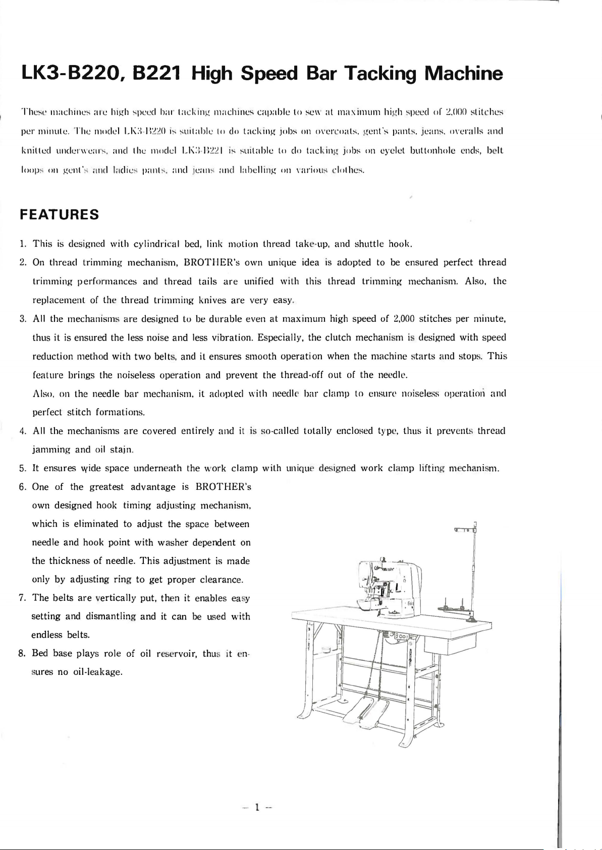
1.
This
is designed with cylindri cal bed, link motion
2.
On
thread
trimming
replacement of the
3.
All
the mechanisms
thus it is ensured the less noise and less vibration. Especially, the clutch mechanism is designed with speed
reduction method with
feature brings the noiseless ope
Also,
perfect
trimming mechanism,
perf
ormances and
thread
are
on the needle
stitch
formations.
BROTHER'
thread
trimming
designed to be
two
belts, and it ensures smooth
bar
mechanism, it adopted with needl e
tails are unified with this
knives
ration
are
durable
and prevent the
thread
s own unique idea is adopted to be ensured perfect
very easy .
even
take-up. and
at
max
imum high speed of
operation
thr
ead-off out of the needle.
bar
clamp
shuttle
thread
when the machine
to ensun• noiseless operaticni
hook.
trimming mechanism. Also,
2,000
stitches per minute,
starts
and stops.
~
and
belt
thread
the
Thi
and
s
4.
All
the mechanisms
jamming
5. It ensures
6. One of the
own designed hook timing adjustin g mechanism,
which is eliminated to adjust the space between
needle and hook point with wa
the
only by adjusting ring
7.
The
setting
endless belts.
8. Bed
sures no oil-leakage.
and oil stain.
wide
greatest
thickness
belts
are
and dismantling
base
plays role of oil reservoir, thu s it en·
are
covered entirely
space
underne
advantage
of needle.
to
vertically put, then it enables easy
ath
the work
is
BROTHER's
sher
dependent on
This
adjustment is made
get
proper
and
it
can
be
cle
used
aranc
and
it is so-called
clamp
e.
with
totally
with uniqu e designed
enclosed type, thus it prev ents
work
cla
mp
lifting mechanism.
thread
- 1 -
-
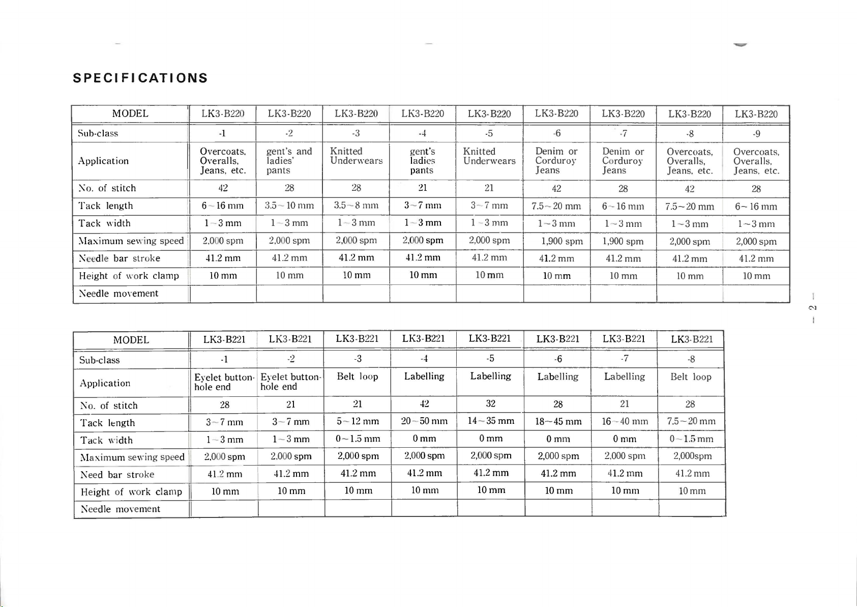
SPECI
MODEL LK3-B220 LK3-B220 LK3-B22 0
Sub-class
Application
;\
o.
of
stitch
Tack
length
Tack
\\'idth
:\Iaximu111
:1\eedle
Height of \\'o
;\e
Sub-class
Application
;\o.
Tack
Ta
1\I
l\
Height of wo
~eedle
edle
of
ck wi
axim
eed
bar
movem
MODEL
stitch
length
um
bar str
movement
Fl
CATIONS
sewing speed I
str
oke
rk
clamp
ent
dth
sewing speed
oke
rk
clamp
I
I
I
I
I
I
I
II
-1
Overcoats.
Overalls, ladies'
Jeans,
etc.
42
6-
16
111m
1-
3ml11
2.000 spm
-!1.2
mm
lOmm
gent's
pants
:3.5-10111m
1-
I
2,000
41.2
10mm
I
LK3-B221
I
-1
LK3-B221
I
I
I Eyelet button-! Eyel
hole end hole end
II
I
28
3-
7mm
1-
3mm
2.
000
41.2 ml11
lOmm
spm
I
I
I
I
I
I
3-
1- 3
2.000
-!1.2
-2
and
28 28
3mm
spm
mm
-2
et
button-
21
7mm
mm
spm
mm
lOmm
Knitted
Underwears
3.51-
2,000
41.2111111
LK3-B221
Belt loop Labelling
5-
0-
2,00
-3
8111111
3111111
spm
10mm
-3
21
12
1.5111111
0spm
41.2
mm
lOmm
mm
LK3-B220
I
gent's
ladi
pan
31-
I
2,000
-!1.2
10mm
LK3 -
20-50mm
Omm
2.
000spl11
41.2
10111111
--l
es
ts
21
7111111
3mm
spm
mm
B221
--l
-!2
111111
LK3-B220
-5
Knitted
Unde
rwears
21
3-
7mm
1 -
3mm
2,0
00
spm
41.2
mm
lO
mm
LK3-B221
-5
Labelling
32
14-35mm
Omm
2,
000spm
4L2mm
lOmm
LK3-B220
-6
Denim
Corduroy
Jeans
7.5-
LK3 -B
18-45
or
42
20
mm
1-
3mm
1,900
spm
4L
2mm
lO
mm
22
-6
Labelling Labelli
28
mm
Omm
2,
000sp
4L2mm
lOmm
1
m
LK3-B220
Denim
Co
rduroy
Jeans
6-
l -
1,900
4L2mm
10mm
LK
16-40111111
Omm
,000
2
4
1.2111111
10m111
-7
or
28
16111111
3mm
spm
3-B22
1
-7
ng
21
sp111
LK3-B220 LK3-B220
-8 -9
Overcoats,
Overalls, Overalls,
Jeans, etc.
42
7.5-20
7.5-20mm
mm
1-
3mm
2,000
spm
41.2
mm
lOmm
LK3-B221
-8
Belt loop
28
0-1.5mm
2,000spm
41.2111111
lOmm
Overcoats,
Jeans,
28
6-16111m
1-3ml11
2,000spm
41.2
10mm
I
etc.
mm
N
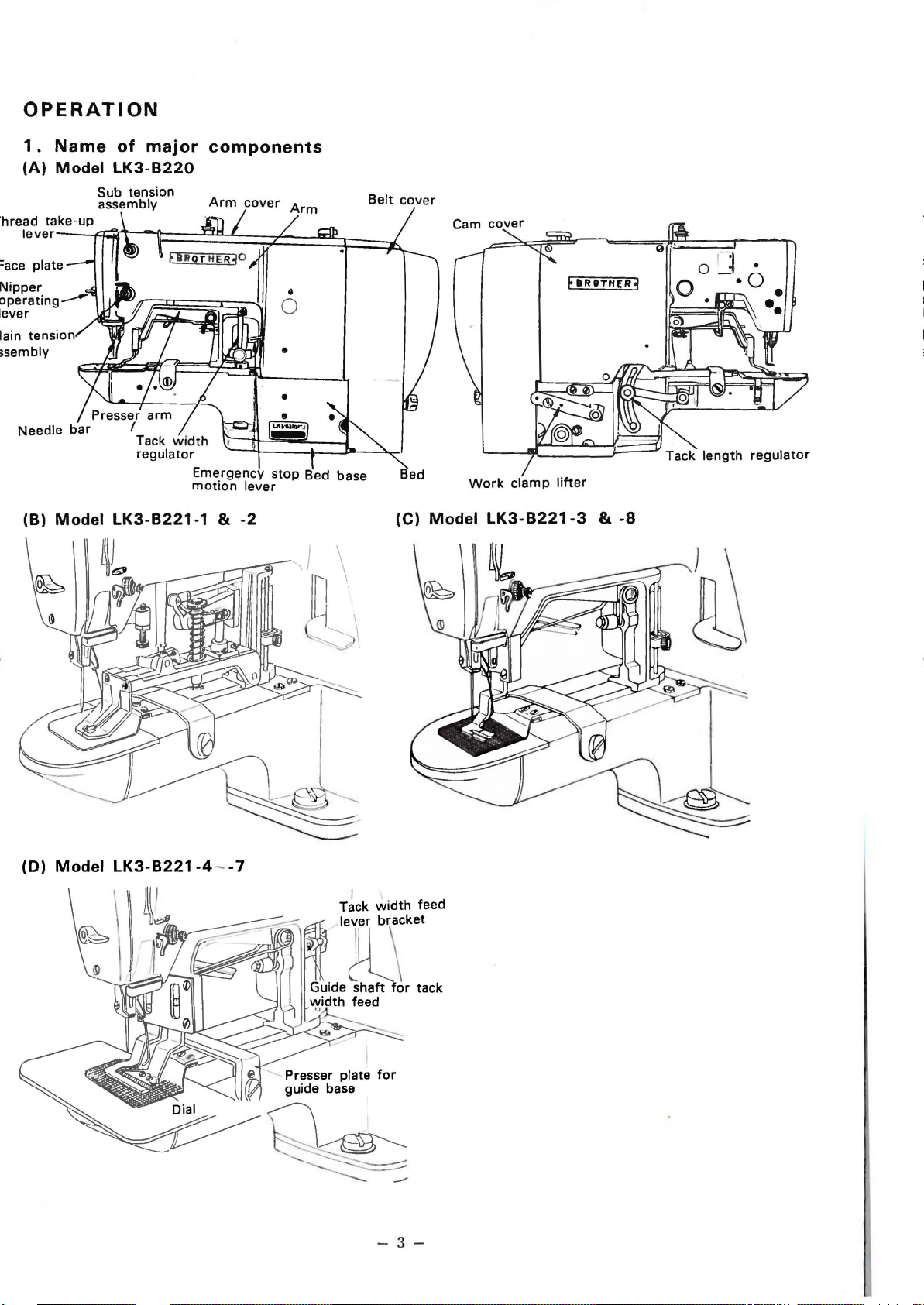
OPERATION
1.
Name
(A) Model
lever----ffff1~~====~~==~~==~~==~.(
plate
Nipper
tension
of
major
LK3-B220
Sub tension
assembly
components
Arm
cover
Belt
cover
Cam
cover
F
UDTHER3
Needle
bar
(B) Model
Presser
arm
I
Tack
regulator
LK3-B221-1
width
Emergency
motion
&
lever
-2
stop
Bed base
Bed
(C)
Work
Model
clamp
lifter
LK3-B221-3
&
-8
(D) Model
LK3-B221-4--7
-3-
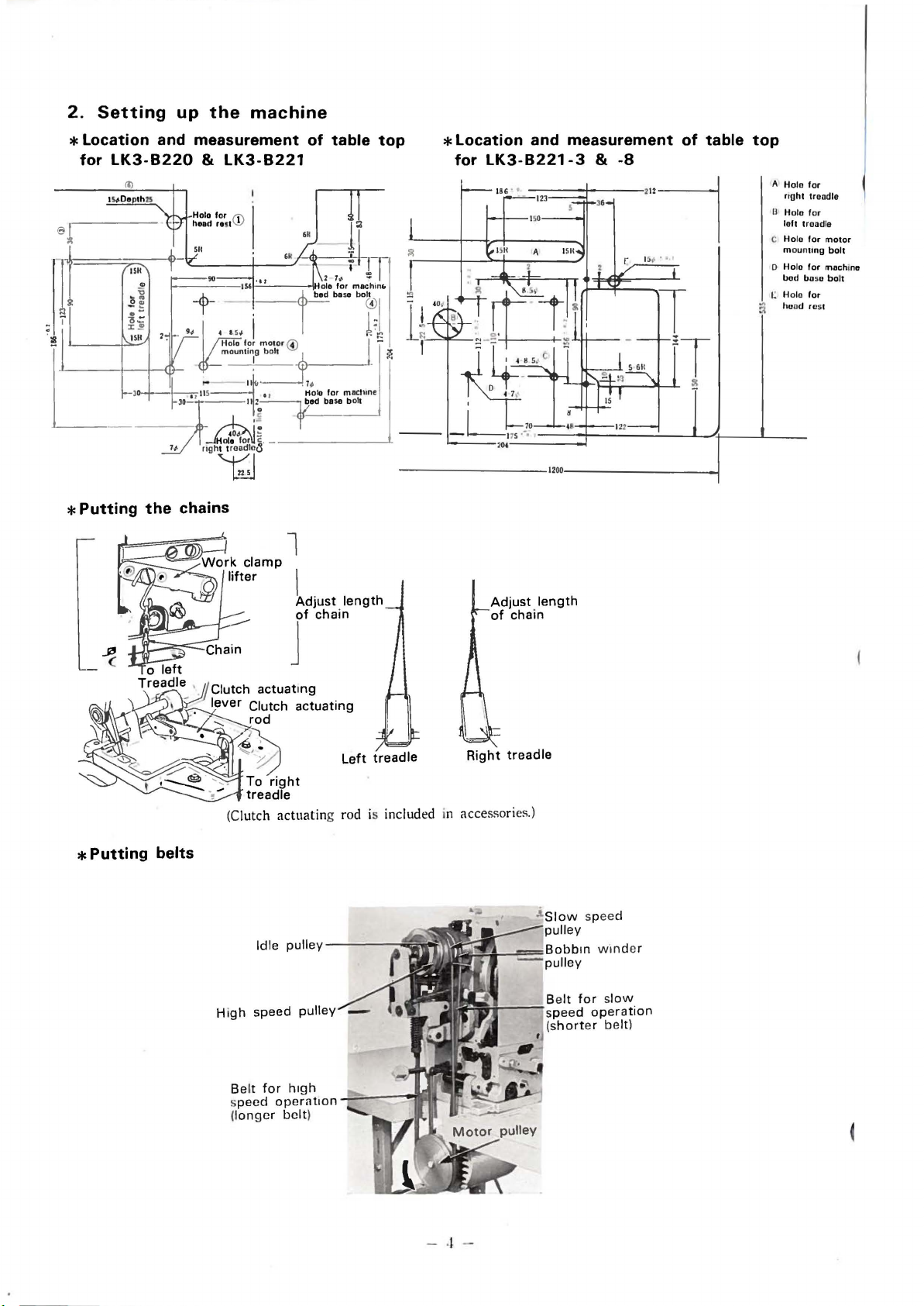
2.
Setting
up
the
machine
* Location and measurement
for
LK3-B220
*Putting
the
&
chains
Work
LK3-B221
l
clamp
lifter
of
l
Adjust
J'
oh•;"
table
length
top
* Location and measurement
for
LK3-B221-3
----------1200----------..j
Adjust
of
chain
length
&
-8
of
table
top
A Holo for
ng
ht troodle
U H
ofo
for
lo
ft
troodle
C Holo
lor
mounung
D Halo for machine
bod boso bolt
t:
Holo for
ho
nd rest
motor
bolt
*Putting
o
left
Trea~Je_
r-.~'""'-
'.§Clutch
, lever Clutch actuating
"'
.__,.
· ·
actuatmg
rod
(Clutch
actuatin
belts
Belt for h1gh
speed operat1o
(longe
r belt)
Right
Left
treadle
g rod is included in accessories.)
n
treadle
wmder
- ·l -
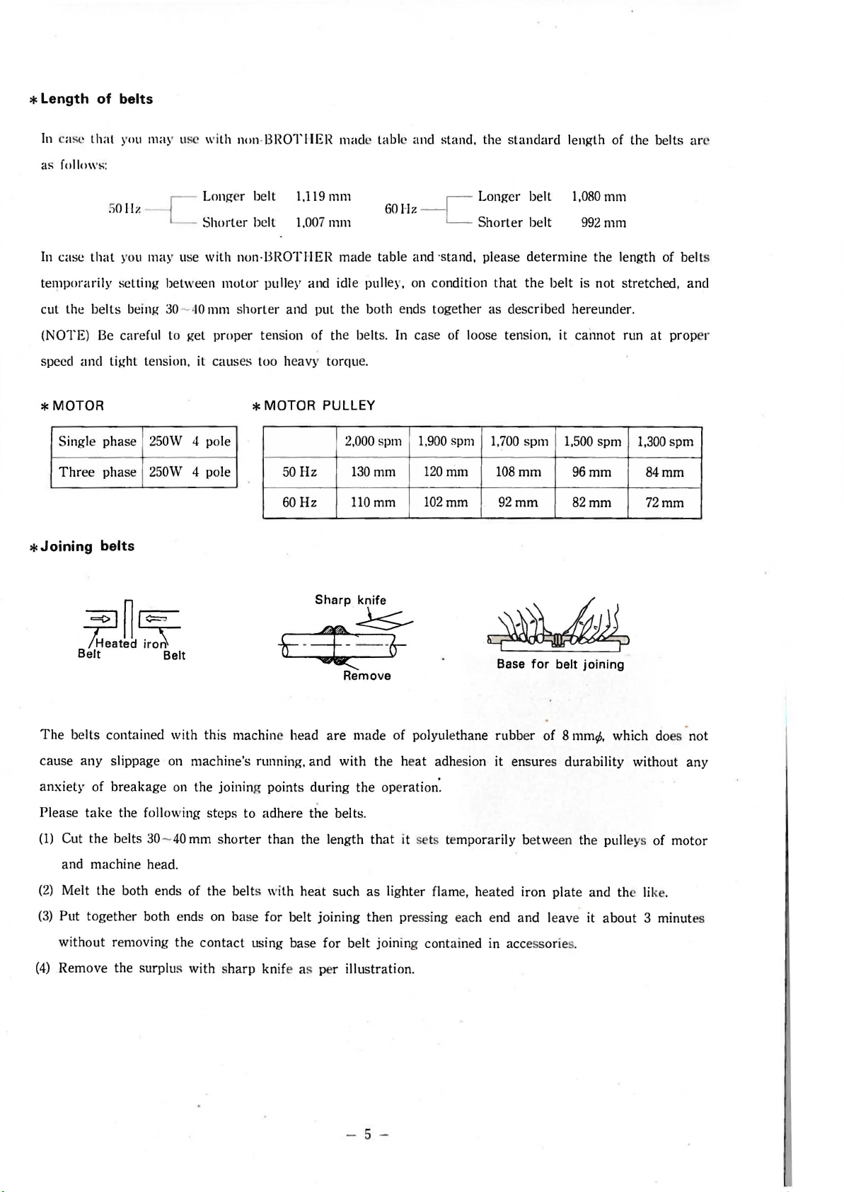
* Length
In
of
belts
·asc th at you may usc
\\'
ith non-
BROTHER
mad
e tabl e
and
stand, th e
standard
length of
the
belts arc
as follow
In
case
temporarily
cut
the
(NOTE)
speed
and
*MOTOR
Singl e
Three
*Joining
s:
50 liz
-c
that
you may use with non-
sett
ing between mo
belts
being 30- 40 mm s
Be careful to
tight
phase
phase
belts
get
tension, it
250W
250W
4 pole
4 pole
Longer belt
Short
er be
lt
BROTHER
tor
pull
hort
er
prop
er tension
caus
es
too heavy
*MOTOR
1,119mm
1,007
llllll
made
ey
and idle pulley, on condition
and
put
the both ends together
of
the belts. In case
torqu
60H
z
-c
table and ·stand, please
e.
PULLEY
1,900 spm
120
102mm
50
Hz
60Hz
2,000 spm
130mm
llOmm
Longer
Sho
of loose
trim
rter
that
as
descr
tension
1,700 s
108mm
92mm
belt
belt
determine
the
1,080
992mm
the
belt
is
not
ibed hereunder.
, it
cannot
pm
1,500
96mm
82mm
mm
length of
stretched, and
run
at
spm
1,300
84mm
72mm
belt
prop
spm
s
er
~~§:
/Heated~
Belt Belt
The
belts
cause
any
anxiety
Please
(1) Cut
(2)
(3)
(4)
of
take
the
and
machine
Melt
Put
together
without
Remove
contained
slippage on
breakage
the
following
belts 30 -
the
both
both ends on base
remov
the
surplu
head
ends
ing
with
this
machine's
on
the
40
mm
.
of
the
contact
s with s
machine head
running,
joining points
steps
to
adhere
shorter
the
belts w
using
harp
than
for
knif
Sharp
knife
~
t=-=-I;
and
during
the
the
ith
heat
belt
base
e as per
- -
6--
Remove
are
made
of
polyule
with
the heat
the
operation:
belts.
length
joining then pressing each end
for
that
it sets te
such
as lighter flame, heated
belt
joining cont ained in accessories.
illustration
.
Base
thane
rubb
adhesion it
mpor
arily between the pulleys
for
belt
er
of
Smm¢,
ensur
es
durability
iron
plate and the like.
and leav
e it
joining
which does
without
about 3 minut
of
not
any
motor
es
- 5 -
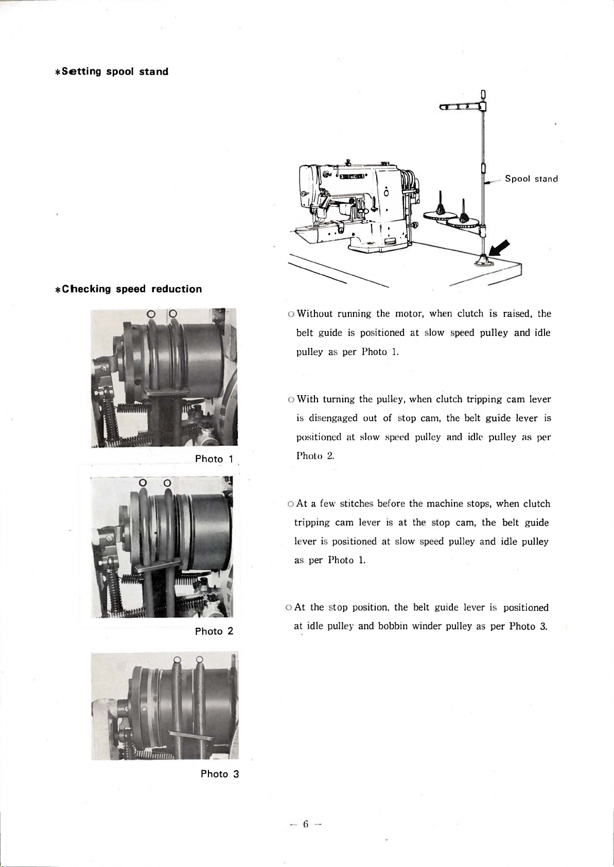
*Setting
spool stand
*Checking
speed reduction
Photo 1
o
Without
belt guide is positioned at slow speed
pulley as per
o
With
is disengaged out of s
positioned
Photo
o
At
tr
ipping
le
ver
as
running the motor, when clutch
Photo
1.
turn
ing the pulle
at
2.
a few sti
cam
is positioned
per
Photo
slow speed pulley and
tch
es before the machine stops, when
lever is
1.
y,
when clutch tripp
top cam, the belt g
at the stop cam, the
at
slow speed pulley a
is raised, the
pulley
ing
uide
idlt>
pulley
belt
nd
idle pulley
and
cam
lever is
as
clutch
guide
idle
lever
per
o
At
the stop position, the belt guide leve r is positioned
at
Photo 2
Photo 3
idle pulley and bobbin winder pulley as per
6
Photo
3.
3.
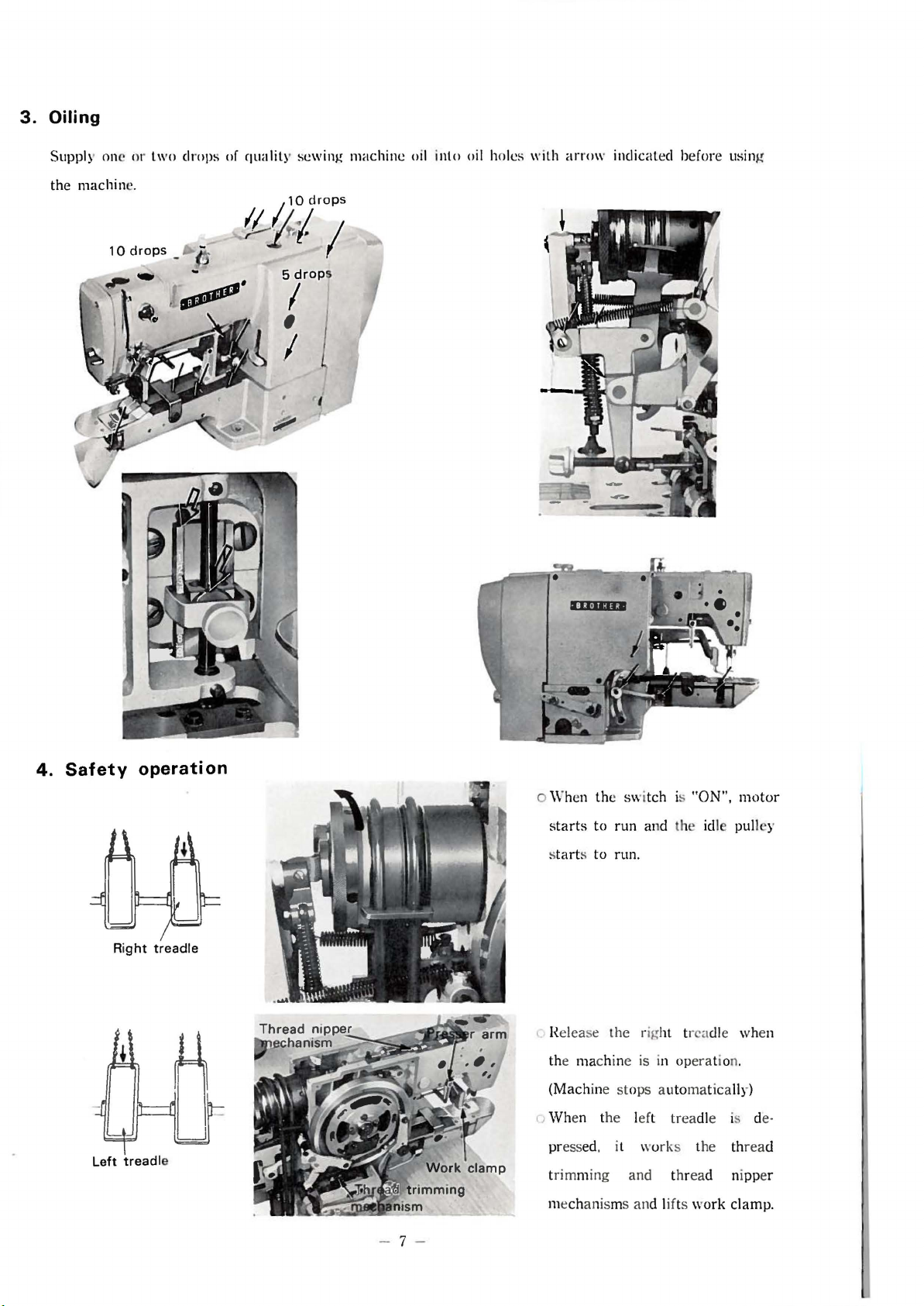
Oiling
Supply one or two drops of quality sewing machine oil inlo oil holes with
the machin
e.
10drops
1
10
drops
!14
5
drop
I
s
(L-
I
'
I
' I
arrow
indicated before using
4.
Safety
Ri
Left
operation
ght
treadle
treadl
e
o When the switch is "ON",
s
tarts
to run and the idl pulley
s
tart
s to run.
l Release the right tr a
ma
the
(Machine
r;
When the left treadle is d
pressed, it works the th
trimming and thread nipper
mechanisms
chine is in op
st
ops automatically)
and li
era
fts work clamp.
motor
dl
e when
tion.
rea
e-
d
- 7 -
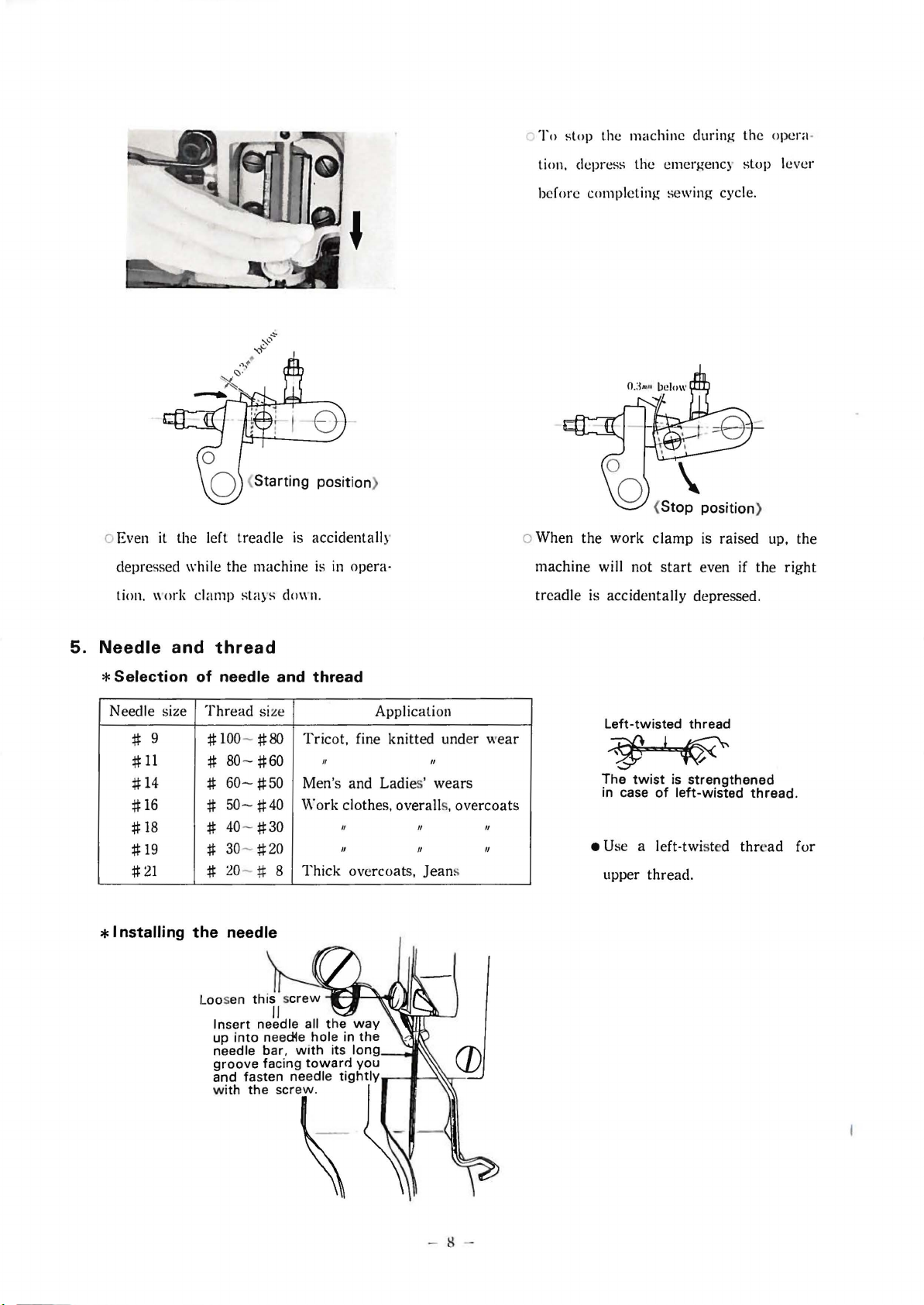
To
stop the machine during the opera -
tion. depress the emergency stop lever
o Even
it
depressed
the left treadle
while the machine
tion. \\'ork clamp
stays
is
accidentally
is
clown
.
in
opera·
before completing
o When the work
machine will not
is
treadle
accidentally depressed.
sewing cycle.
position)
clamp
is raised up, the
start
even if the right
5.
Needle
*Selection
Needle
*Installing
#
#11
#
14
#
16
#
18
#
19
#21
9
and
size
thread
of
needle and thread
Thread
#
#
#
#
# 40-
# 30-
#
the
Loosen
up
needle bar,
groove
and fasten needle
with
size Application
100-#80
80-
#60
60-
#50
50-
#40
#30
#20
:W
- # 8
needle
this screw
needle all
into
the
II
need4e
facing
screw.
with
Insert
Tricot,
fine knitted under
II II
wear
Men's and Ladies' wears
Work clothes. overalls, overcoats
II
II
Thick
overcoats,
.,...;w~......:~
the
way
hole
in
the
its
toward
long _ ___,.,,,
you
tightiY--t
II II
II II
Jean
s
J--->...\.,
,........-J
Left-twisted
thread
~
The
twist
is
in case
• Use a left-twisted
upper thread.
strengthened
of
left-wisted
thread.
thr
ead for
*List
of
needle
LK3-B220-1
LK3-B220-2
LK3-B220-3
LK3-B220-4
LK3-B220-5
LK3-B220-6
LK3-B220-7
LK3 -B220-8
LK3 -B220-9
to
recommended
be
LQ x s
LQ x s
LQ x s
LQ x s
LQ x s
DPX17
DP
17
LQ x 5
LQ x 5
#
16
#
16
#11
#
16
#11
;!:!:
21
#21
#
16
#
16
LK3-
B221
-l DB X 1
LK3-
B221
LK3-
B221
LK3-
B221
LK3-B221
LK3-B221-6
LK3-B221-7
LK3-B221-8 LQ x 5
-2
<3
·4
-5
DBx 1
LQ x s
DBx 1
DB x 1
DB x l
DB x 1
#1
#
14
#
16
#11
#11
#11
#11
#
4
16
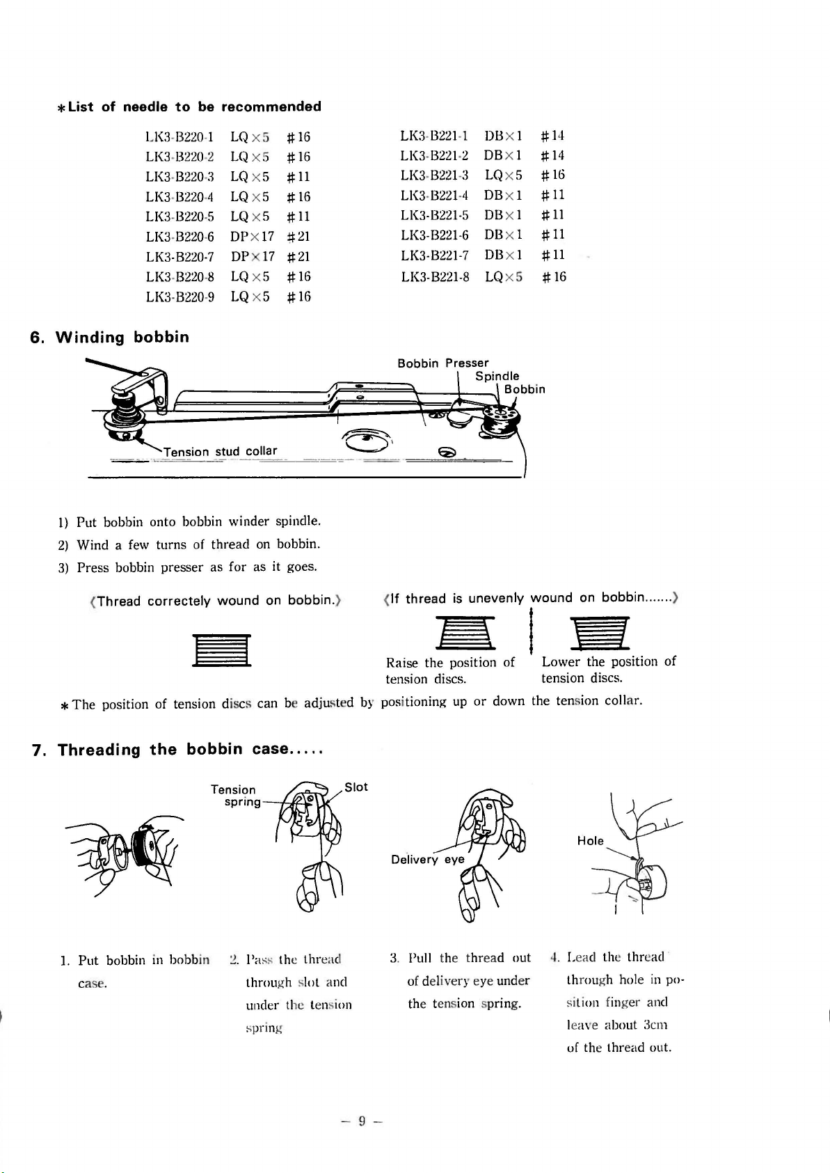
Winding
6.
1)
2)
3)
*The
bobbin
Put bobbin onto bobbin winder spindle.
Wind a few turns of thread on bobbin.
Press bobbin presser as for as it goes.
(
If
(Thread correctely wound on bobbin. }
position of tension discs can be adjusted by positioning up
thread
Raise the position of
tension discs.
is
unevenly wound on bobbin ....... )
~l:e
Lower the position of
tension
or
down the tension colla
discs.
r.
7. Threading
1.
Put
bobbin in bobb
case. through slot and
the
bobbin case
in
.....
Tension
spring-~"'--10:
~
-
!'
ass the thread
under the tensi
spring
Slot
on
- 9 -
3. Pull the th
rea
d out 4. Lead the thread
of delivery eye under through ho
the tension spring.
sition finger and
leave about :km
of the thread out.
le
in po·
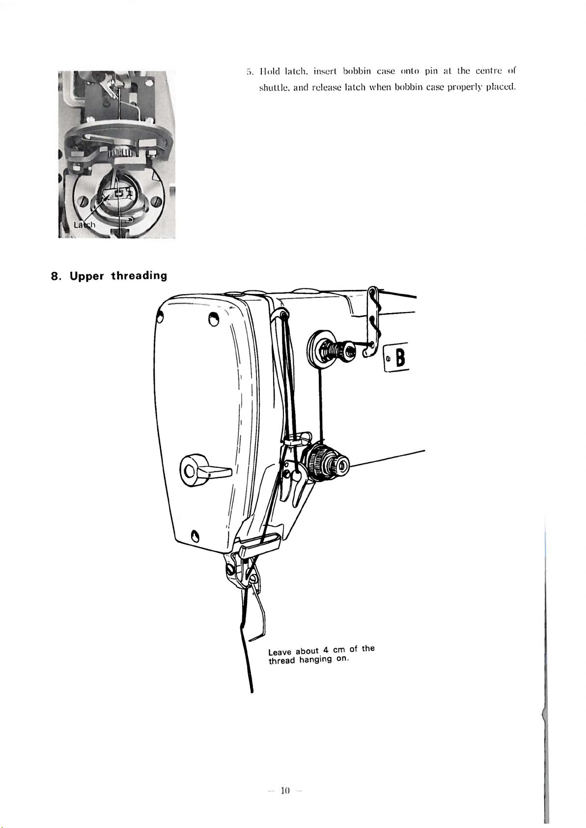
8.
Upper
threading
S.
II
old
shuttle,
latch.
and
ins
ert
release
bobbin
latch
case
when
onto
bobbin
pin
case
at
the
properly
centre
placed
of
.
Le
ave
about
thread
-
10
hanging
-
4 em of
on.
the

9.
Thread
tensions
*Lower
*Upper
thread tension
\
thread tension
Adjust the lower
pulling the
Me
asure the tens ion
After adjusting the lower
means of the main tension.
thread
thread
from the bobbin case.
tension so
by
the tension gauge as per the illustration.
that
you will feel a slight resistance
(15-30
thr
ead tension, adjust the upper thread tension by
gram
s for
#50
cotton thread)
in
* Main tension
This
adjustment is affected the sewing condition, therefore , adjust the tension to be following list
dependent on sub-class,
LK3-B220-1--5, -8LK3-
B220-6
LK3-B221-4
When the thread is trimmed
the upper
*Sub
Sub tension plays a role to prevent the upper
Adjust the sub tension
material
(40-50
*Thread
Thread--{]
guide ; :
thread
tension
when the machine stops.
gr
. for
take
Stroke Thread
>-.,.
'\~~r.~·
:)
should be left put of the needle eye.
B220-6--7; 5-25
up spring stroke and
..
~Ten©n
thread
- -7 ............ ...
- -7 ................
so
~
after
that
T .
eusron
gauge
and
materials
-9,
8221-1 -
...........................
..........................
the
main
the upper
gr. for all
its
Th
is adjustment is also affected much on the sewing condition.
LK3-B220
LK3-B221
LK3-B220
LK3-B22
.
Tension
-3,
-8
.......... 70- 80 gr.
150-200
50-
tension is released
thr
ead from loosening when the
thread
oth
tension
-1--5, -8-
-1-
-6- -7 .................................. 6- 8 mm
1-4- -7 ............................... 12.5- 13.5 mm
will be fairly taut betwee n the needle and the
er sub-classes)
-9
-3,
-8
gr.
60
gr.
at
}
························
Thread
Dacron
Cotton
Dacron
the final stitch, enough length
S
tro
3
#50
#50
#80
ke
mm
thr
ead is trimmed.
Tension
15- 20
220-300 gr.
15-220 gr.
of
gr
.
-
11
-

10.
Adjusting
tack
width
11.
Adjusting
g
tack
length
Adjust by loosening adjusting screw and
1
2.
13.
moving hinge
Adjusting
Cleaning
bluci<
in
vertical direction.
pressure
shuttle
of
work
clamp
Adjust the work
than necef.sary
Adjust by loosening thumb screw and moving
along with the slot of the
clamp
so
that
to prevent the
tack
it
exerts
material
length
no more pressure
from slipping.
regulator.
it
1.
Remove shuttle
bobbin case. oil inside of shuttle race.
14.
Removing
R move four flat he
plate.
race
needle
ad scr
with
plate
ews and then needle
2. Remove shuttle.
15.
Match
- 12 -
Installing
markin
* After cleaning, put a
needle
g in assembling.
plate
drop
of

~
Set
screw
Thread
Upper
Lower
1
6.
presser
thread
thread
__
knife
knife
Replacing needle
*Needle
(2.2mm
diameter) for ultra
hole plates are available
in
needle hole diamete
hole
plate
in
r)
for thick
hea vy materials.
Thread
Presser
*The
Upper
needle hole plate can be removed by loosening two
set screws and pushing it upward.
be
very smooth.
* Replace the needle hole plate
siderably damaged.
*When
putting a new needle hole plate
make sure the
groove
in
standard size (1.6mm
mat
erials , and another special size (4.0mm
thread
knife
Lower
if
thread
The
needle hole must
the needle hole IS con-
in
groove on its underside is
in
the needle plate .
in
needle hole diameter); and special size
in
knife
replacement,
line with the
needle hole
ADJUSTMENTS
1.
Adjusting
The
proper needle
the
lowest point to form the correct loop of the upper thread a
the loop.
needle bar
bar
rise and needle
bar
heig
ht are necessary for the needle in its upward trave l from
( 1 ) Needle bar rise
When the needle bar comes up from downmost to
mentioned measurement, the shuttle point must be in line
\\"
ith the centre axis of the needle. Adjustment can be
made by loosen
turn ing the shuttle
screw matching with the
black screw.
- 13 -
nd
for the shuttle point to properly hook
below-
in
g two shuttle driver set screws and
driver as required and fasten the silver
groove
of low
er
shaft a
nd
then

Shuttle driver
(2)
Needle bar height
Shuttle Needle
p~~
ll
r-1
'l1T2
~·
Make
sure
Lhal
the shullle driv er is
of shuttle point.
LK3-
B220
-l - ·5, -H- -9 } ........ .
LK3-
B221
-l - -3, -8
LK3-B220
LK3-
(NOTE) LK3-
When
the
shuttle point is
distance between the lop of the needle eye and the shuttle point
If
adjustment
raise
or
is
required, loosen the needle
lower the needle bar.
LK3-
8220-1 - -
LK:~-
B221-l LK3-B220-6-
LK3-B221 -4- -7 ......
·6- -7 ...... ......
B221
-4- -7
.....................
B220
-6 & -7 for Denim. only one screw is sel.
in
line with the
5.
-8-
-9
) .
..
-3,
-H
-7
.....................
J
..........
.......
in
close
2.8
..........
...
..
2.5
2.5
centre
2.0
1.2mm ± 0.2mm
2.0mm ± 0.
axis
bar
111111
contact
111111
mm _ O.lmm
mm 0.2
connecting stud
± 0.
3mm
3mm
with lhe
±
0.2
111111
m111
of the needle, the
is
rear
as
follows.
scr
ew
side
correct
and
(3)
Clearance
Needle1C
2.
Adjusting
Bar
tacks
the
outer
The
tack
expanded by feed adjustment, its centre must always be at the same point.
between
- o.
~Shuttle
feed
will be made as the pow er is
and inner
design
the
os....
.
pomt
mechanism
groove
stays
within the re
needle and
s of the feed ca
ctan
the
shuttle point
transmitt
gul
ed to t
m.
ar
opening in the work clamp an d even when the swing ts
ack
length and tack width mechanisms through
Thl'
corr
ect
clearan
tween the centre
bein
).!
met with
po
int is
0.0:~-0.0Hmm
To
adjust the
loosen the s
s
et scr
adjusting screw
the s
et scr
completion.
huttle
ew and
ew tightly
ce be·
of needle
shuttle
.
clearance,
hook
rot
ate
the
and
fasten
after
(1)
Needle and feed cam
Feeding begins as soon as the needle rises out of the materia l and ends before needle comes down into
If
the material.
turn
the feed
Turnin
g the feed
(NOTE) LK3-B220-6
adjustm
cam
ent
by degrees.
cam
in its
is requ ired, loosen the wo
rotat
ing direction, it advances the feed Liming and vice versa.
rm
wheel shaft nut and the
& -7 for Denim. the Liming of feed cam should he advanced a h
- u -
hexag
onal bolt and
it
earlier.

(2)
Adjusting
tack
width
motion
(Except
LK3-B221-4
- -
7)
Adjusti
justments
adjustment was mad e, no further adjustment
First of all, adjust to gel the correct posit ion between work clamp
fram e s
nM
tack width and lack length motions require very delicate and prec ise cautions.
firstly on
el
bolt.
the tack width mot ion and then tack length motion with
is
necessary
the needle hole will
then tighten the
4)
Loosen the
bl
hinge
Again , move the presse r arm and set the presser arm so
the needle hole will come
then
ock all the way down, then tighten th e fastening s
tighten the fastening screw.
unl
ess absolutely required.
come
fa
stenin g scre
tack
width lever fa : tening screw and lower th e
Make
great
care. Once the
and feed plate
I) Let the first needle come down
into the needle hole.
2) Loosen the adjusting screw and
raise the
block
hinge
tack
width regulator lever shaft,
tight en the adjusting
and
3) Loosen the feed bracket, fastening
screw. move the press
sel the
exa
ctly at the centre of work
w.
exactly at the
by
loosening
hinge block until the
is
in lev
el
er
po
sition of bracket so
centr
e of work clamp,
ad-
correct
clamp
with the
scre
w
arm
and
that
clamp
cre
w.
tha
t
,
(3)
Adjusting
tack
length
motion
1)
Raise the clutch and
needle comes down into the needle hole with tack length
regulator
2)
Loosen the feed
regu
of the ta
not so as to move the
:i)
Loosen ba
the ce
tighten the ball stud.
in
the marked position of the rim of the feed cam.
la
tor
rod brings to its fullest ext nt in the elongated hole
ck
length regula tor lever, set the position of
ll
stud and s
ntr
e of
work
turn
the driv
brack
et fastening screw, when the tack length
work
et
the po it ion of press
clamp will come to the nee dle hole, then
ing pulley by hand until
clamp.
er arm
so
tpe
bracket
that
- 1
5-

(4)
Adjusting
I)
2)
3.
Adjusting
The
and
1)
2)
3)
4)
5)
*
motions
Adju~ting
( i) At the
be positioned
(ii)
Make
cycle.
Adjusting dial of labelling
The
When you
neath the dial to its
the pre-determined,
This
lack length motion
~top,
the tack length
In
case of adjustment. readjust the position of feed plate window.
dial plays a role to determine the position of label.
set the material by work
adjustment
thread
upper thread knife, lower thread knife and thread presser
are
oparated by the power
As the needle rises out of the needle hole
thread
The
As soon as the upper
the lower threarl. At this moment, the tip of the upper
The
po~ition
The
the tip of the knife
In
correctly. The
to prevent the thread from slipping out.
thread presser releases the
upper thread knife enters the upper thread loop while the
after
machine stops. When the left treadle is depressed, the connecting rod adjuster disengag
adjusting the knives, firstly remove the needle plate and
on
LK3-B221-4--7
mo
ve
pre~~er
at
the
exte
constant
is
made
trimming
thread
catching the loop in the process of forming the final stitch.
bar
and
n.
mak
e adjustments
plate for guide
centre
nt to fix the position, then you can get
of feed plate window.
at
maximum and
damp,
measurement on the materials.
by
moving the dial back and forth.
ba~e
back and forth
make
~ur
e
put the lab el
~o
that
that
the above position is kept during one
unci ·r·
Labels'~
mechaism
are
mounted to the pinion
transmitted
thread
is
pulled up by the
the connecting rod spring pulls the knives to trim both thread
from the knife
after
the first stitch, the
just before the fifth stitch is formed.
thread
in
the following steps.
cam
.
take
-up lever, the lower thread knife
thread
knife is just
shuttle
make
thread
point comes to its downmosl
sure the knives are installed
the needle hole plate may
presser catches the upper
in
front of the needle hole .
Fastening
~tud
s.
screw
brack
catches
es from
et
(1)
Thread
At
the recess portion of the kni
second stitch, and
trimming knives, the po int of low
is positioned at the red
trimming
the
thr
lever
ead trimming leve r roller is ju st above
at
roller and
fe
the stop position of
mark
of the needle plat
lower
cam,
that
er thread
thread knife
is the
thread
knife
e.
-
16
-
Thi
s adjustment is made by loosening the
a
nd movi
ng it back and forth.
rack

(2) Timing
(3)
Lower
of
knife cam
Lo
oHen
the fastening screw for knife
timing so that the needle may not touch the thread trimming
knives and the upper thread loop
Adjust the thread trimming
so
that
the upp er thread knife ma y hook the upper
during hook point trav
at
the final stitch.
thread knife and thread trimming lever
elling
cam
(B)
downward
cam
(A)
and adjust
may
not touch the knives.
by loosening fastening
thread
with upper thread loop
At the stop position,·
loosen two screws
adjust the thread trimming adjusting screw
that
the point of
thread
sitioned
on the needle plate.
knife will be po·
at
the red
the
screw
loop
and
so
lower
mark
(4)
Adjusting thread
trimming
~hole
~pper
stopper
thread knife
screw
When work
so
that
0.
3mm
At
this moment, the needle hole is positioned
of upper thread knife.
clamp
thread
from the bottom of knife
is lifted up, adjust by stopper
trimming lever roller
cam
may
.
be
apart
at
the
screw
about
rear
- 17 -

(5)
Tension
4.
Adjusting
As the needle begins to rise for the final stitch, the upper thread knife enters the upper thread loop.
And the main tension
When the left treadle
needle
Before the needle comes down for the second stitch, the thread nipper
is
tightened. Make adjustments, if necessary, in the following manner.
of
connecting rod spring
the
thread
is
released
is
depressed, it
bar
thread nipper
If
the connecting rod spring has too weak tension, the knives
often fail to trim the threads and in.some
break
. If.
with the needle causing to
has too strong tension
knives. thus the machine does not work smoothly .
spring
spring hook left
tension, loosen the spring hook set screw and move the
or
extra
right.
on
power will be needed to
extreme
the other hand, the spring
cases, collide
To
nipper
to
allow sufficient length of the thread for the knife.
works
is
lightly tightened to prevent the thread from slipping and being jammed.
the thread nipper mechanism and
is
released and the main tension
at
the first stitch, the
drive
the
adjust the
(2)
Adjusting timing
Adjusting
screw
----Ill
of
the
thread nipper
-.....~at-----Thread
\l!..--f"
--
nipper
lever
n;pp"
7>--+~
shaft
nipper
pawl
lever
(1)
At the stop position, adjust the roller position
so that
marking.
adjusting
Timing
•haft
0 Guide
its
line
f
centre
shaft
will be matched with the red
At the position of the
roller being over the
cess posit ion of the
the end of guide
must be positioned
upper line of the cam.
In case of adjustment,
loosen the fastening
and
rotate
nipper shaft.
the
re·
cam,
shaft
at
the
screw
thread
-
18
-

(3)
At
the
stop
position (before lifting work clamp), the end of guide
of
cam
on the condition
In
case
of adjustment, loosen the
shaft
and adjust to bite the
lightly. (At
At
this position, when the
the bollom of the recess portion of the cam.
that
time, the roller position is
that
thread
the
thread
thread
thread
nipper
shaft
nipper stop lev
nipper adjusting lev
nipper adjusting lever pawl· and
2mm
slop lev
er
contact
apart
from recess portion of the cam).
er
is disengaged, adjust the roller to move smoothly
s the thread nipper adjusting lev
er
screw, fix the position of the
must be positioned
stop
lever, then fasten the
at
the lower line
er
thread
nipper
pawl.
screw
to
(4)
the
At
recess portion of the cam, adjust the tension
adjusting thumb screw so
will be light and
being
it
5.
Adjusting
Unless the clutch and
consumed for the machine's operation,
position of the roller being
at
the position of the roller
in
the recess portion of the cam,
so
that
the main tension will be loosened.
clutch
and brake
brake
that
the main tension
are
over
in order, the machine may not stop properl y,
(5)
the
At
the position of the lever pawl being
out of the stop lever, adjust the
adjust
or
machine's durability may be considerably lessened.
moving left and right so
guide
ma\' catch
the
thread
that
surely.
the needle
more
thread
bar
power
released
nipper
thread
may
be
In
case of adjustment, please follow the instruct ions.
(1) Clutch lever catch and clutch stop latch
Adjust the position
the clutch stopper is about 3 mm.
(2)
At
the position of trippi ng do g being ov
arc
at the idle pulley and th e slow speed puller.
of
the
clutch
stop
latch so
er
that
the
mm
imum distance between the stop
the stop cam. adjust the level of belt guide so
- 19
that
cam
and
the belts

(3)
At the position of tripping dog being out the stop cam,
adjust the position of the stopper so
are
at
the idle pulley and the high speed pulley.
'
Bobbin
Idle pulley
winder
5~5mm
pulley
\1~
(
5)
Timing of stop cam and clutch stopper
Please adjust stop cam so
may disengage with clutch lever catch one stitch
before the end of sewing cycle.
please see
with clutch lever catch within
sition where the groove of stop cam falls into line
with clutch stopper. In case of adjustment, loosen
two set screws and move stop cam left or right to adjust. At
by turning high speed pulley by hand.
that
the belts
(4)
Adjusting height of trip-
ping dog
Please adjust the position
of lever so that clutch may
come into function when
tripping dog reaches three
quater position of stop cam.
that
clutch stop latch
In
that
clutch stop latch
that
time, make sure to get proper timing
will
±30·
from the po·
of
this case,
disengage
(6)
Pressure of
Adjust the clutch lever spring so
to permit the clutch stopper to fit positively into the groove of
the stop cam to
loosen the fastening screw and change the angle of the adjusting
plate
(7) Pressure of the stop spring
If
the
stop spring is too weak
down into the material as the machine is going to stop
machine may stop
stop spring is too strong
machine
adversely affect the durability of this machine. Adjust the stop
spring tension
-
the
clutch lever spring
that
it has just enough tension
stop
the machine gently.
.
in
tension, the needle
at
wrong position. If, on the other hand, the
in
tension, the impact exerted on the
at
the time of stopping will be increased and this will
by
turning the nut.
20
-
In
case of adjustment,
may
come
or
the

(8)
Position
When tripping dog is
by
loosening fastening screw so that the distance between the
ann
hole and emergency stop lever
of
emergency stop lever
at
the highest position of stop cam, adjust
is
about 1 mm.
(9)
Clutch
lever
In
case that the right
treadle is depressed
strongly, it causes the
belts coming off out
of the pulleys due to
too much movement
of the clutch. In order
to avoid this, adjust
in
the following
manners.
*At
the starting, set the shaft by the fastening screw so that the actuating lever shaft contacts with the
of
lever pin and adjust to get the distance
the lever. After completion, take off the screw.
3mm between the bed and the clutch actuating lever by lowering
(1
0)
Clutch actuating lever stopper
In order to prevent the right treadle from going upward, the
clutch actuating lever stopper is limited the movement of the
clutch actuating lever. In case of adjustment, adjust in the
following manners.
1.
Be
the machine
2.
Fix the actuating lever shaft with set screw.
3.
Set the machine in normal position.
4.
Adjust the height of the stopper to be 1 mm by loosening
nut.
5.
After completion,
(Set screw
is
included
at
stop position.
take
out the set screw.
in
the accessory box)
actuating
Nut
6.
Adjusting
While the machine is
and also the knife bar remains inoperative. When the left treadle is depressed after the machine has
automatically stopped, the knife
clamp is raised
work
up.
clamp
in
lifter
operation, the work clamp stays down even if the right threadle is depressed
bar
tripping lever is actuated to operate the knives and then the work
-
21
-

t:-. case of the adjustm ent. do m the following manner
(1)
At the stm.)
onnc
ctor
l:.tch
is
(2)
Fasten set screw for latch
connecting lever.
position, when the left treadle
I o o
i
erat
c with the clearance of less than 0.3 mm as the work clamp connecting lever
1
adjascent with the clutch actuatinR" connector lever stop.
at
the position
(3)
In
to be less than about 0.3 mm between clutch connector lever
stop and work clamp connector latch
(4)
When the left treadle is depressed
engage until the work clamp
(5)
(6)
(
7)
is
depressed, adjust the length of the clutch
that
the operation, adju st
make sure that the thread
the clutch actuating connector
the adjustment mentioned
When the left treadl e is depressed upto th e stopper, adjust the
height of the work clamp to be
Adjust the height of the presser arm to
the pres
At the stop position, when the tett
before the thread trimming rnechani
relation b tweem the
ser
s.
actuating
the lower portion of the latch meets work clamp
by
work clamp
trimming mechanism does not
con11eC.ting
lewr
in
step
arm and the presser
<:;top
lever
10
<>haft
lever the
as
per Page. 8.
after
the machine stopped,
lever latch is out of
step. if incomplete,
~)
a
nd
3)
.
mm
::~part
from the feed plate.
Le
2.5
--3.0mm between
<>priug
by set screw.
i-r
eadle is depressed,
o;;m 1s
Hnri
engaged, adjust the
the collar so
ueedle
1
:;
tightened.
bar
clearance
repeat
just
that
the
thread guide
7.
Adjusting
The
two presser feet
when the work clamp is depressed and
catch
the material up between the left a
In case
becomes very dirty.
In the adjustment,
(
1)
Amount of opening bet ween the feet can be adjusted by the nut (!).
(2)
In case
being d
guide towa rd you.
(3)
At
the stop position, in case that the feet wi
loosen nut
work
that
this action mar not work
that
the feet will not be closed when the right treadle pedal is
ep
re ed th right treadl e pedal, uns
clamp
a.-
e opened about 2 mm when th work clamp
do
iu the follow ing manners.
on
8221-1
actuat~d
nd
in
good condition, the sewing ref.l!lt on eyelet buttonhole
and
right.
crew
-2
1.
he ma chine by treadle peda
the fastening screw ® a
ll
not open when the left treadle pedal 1s depressed,
® and adjust th e he ight of stop lever adjusting screw.
-
22
-
are
lifted up. T he feet will be closed
l.
In this case,
dep~
essed,
at
nd
pull the feet closing
the stop po si tion,
the
feet
end
bar

(4)
In case that the feet will
closed when the right
be
treadle pedal is depressed and
before the machine s
just
the length of the fed
closing conn 'clor bar.
8.
Needle
cooler
not
tart
s, ad-
mechanism
*This
machine can be used
with the needle cooler
vice
at
your option.
case
that
you may need,
please contact y
This
need le cooler device
is featured to
thread breakage with s
thtic
thr
mum high speed of
stitches
per
ad even
minute.
our
avoid the
at
de-
In
dealer.
yn-
maxi-
2,000
Needle
cooler
adJUS
'
oCock
you use th is machine with
\Vhen
vertically and if no
0
Thumb
Adjust oi I flow depending on the thi
th
o
If
o Sylicone o
Use ~ 1
rea
you
d.
screw
turn
thumb screw clock,vise, you
il
00 syl
t, close the cock .
icone oil which is avai lable
Oil ta
ter
syntht ic
ckne
nk
thread. open th c
ss of the
can
by
materia
get less
BROTHER.
oil
ock
ls and
flow.
-
23
-

PARTS
LIST
for
LK3-B220
INDEX
l'nr
ta.
Nn. Wd . Nu ,
001401
.4·06
()(I!J.I02.0·1
~~~~~~~~8~1~·6~·1~2c-I-~A7.~7~3--
1
-
009670-5-
IM~J670
.6.12
t)()l;oi670
-7-l·l J .J
UO'JGH0
-6-12 A
i
--'
===
009680·7·13
009680·8·
009681
·2·
009681··1·1·1
~
0<W~~71~o~·7~·~·2c-l--~~~·~4
1
00~711·0·1
00~711·0·14
1~011~~~71~t~·2
:;-·~t2~1--~~~
009711
·4·12 A ·l
1
~009~~71~2~
·0~·~12
,.
009761
·0·12 C·
009761
·2· 12
009761·4·12
O<W771·0·12
009771·4·12
01~1781·4·12
,
__
009=."'112:::1c:·6::..>
,.
009822·0·12
013680·6·12
013710·5·
01~10·7·12
013711
'0·12
01376<1
·6·
Ol37f>ll
·7·
_0::.:I"'3.:.;76'CI"·<::..I·.:.:l2:.._ir~A;i..;;·6!~r,--t------l
1
1
~--------t---~~~.ss~,---+---------l----------1·---a;~·~.25~--·r---------
013761
·2·
013770·6·12
01~80·7·10
014680-6·
014760·6·
l------l
1
------f--..;F.;,;-
I-------+-~·~
Z·
40
2
11·3
14
1
1-53
A·57
:.:..
14
10
·
22
22
-:cl
-t--..;
!71.-::6:;.2--l
A
-71
I
·6fo
II
..
~;.
E·
2
1;
..
J ·I I 021
•.
~771---l·
11·
100
~-3
11·
I ·31 I
1
.:12
~r-~~~~·~~9
/19
F .u; A ·67 104212·0·
C·37 E·24 104450·0·
1·37
A·
C·
73
G·39 Z
C·7·1
11·9
11·37
11·:1
E·3!1
.:.:l2~r--F.;:;:-:;.28:;;--·t------t
F·38
11·45
C·78 025770 ·• 32 C ·53 106744·0·03 E·33 115593·0·
.7
1;
ll·H
1;.24 Ll·27 105812·
12
C·86
1·'1 E·32 105831·0·
ll·f.G
I ·6
C·70
12
1;.53
l2
I ·57
11·36
Z·21 G·49 1·18 I Z·
12
11·21
11·27
K.:llt C·67 106812·0·
11·51
Z·32 D·28 107038·0·01
11·23
8·22
8·57
11·6.<;
I ·70 Bl6302·0.00 C·62 C 49 117936·0·01
11·14
ll·33 Bl7502·2·42
K-73
C·83 047603·6·42
C·84
1>·6
~:.
-.-.;.zg;;;-:.":4~7--1
;·~3~5
G ·41 IJ.12
1; ·42
11
·5 081004-0·70 J ·2 108920·0·
11·67
II·!J.I
C·IO F·
~;.45
:::~5
017761
·6·
12
017771·4·12
017781·4·12 C·92 100062·0·03 F·IO 110191·0·01 J ·24 !41285·0·01 C·IS
1
--:o~t-=77=:8:::2~·0:-·1;.;2:--t-~~:;.
l---~---r--T.E~·30~-4------I
018102·0·20
11·27
1>·29
..
-=-=ss--:-4-----
C·68
C·R7
Wcmnrk
0
I ·
------·
r.
·------
1 IJ-I!f
1M
tt
l2
~r.
__
______ 1 ______
.
1
15
----------1~,~~2~t
4
17 I ·17
---+----------I
IS
Pnrtt, Nu .
0210(~)
02HX~I·I·O·I
I~'i'2~14~1~MI~·I~·';"
Ullf)K0
11
217
10·2·112
h ,.,,2,.1
7"'lil
'"'t"".
71
0·1·03
~7~~.2~·o~2~
0217M0·3·0~
11
21K
211
--'0~
2~1~H60~·
1125001·2·32
025060·
025080·1·32 t:·4 C·96 115548·0·
0251110·1·32
025680·2·32 G·56 105230·0·01 I ·5 115552·0·
--'
0257111·1·32
Ht'f
.1.02
·2-n
2"·'"''2' 1----;1;;., .
·2·
~·2~·1~12c-
2·3·1
. Nu.
A·
7.
.:lfl
;;-
I--~7.;
··~·1~1--I------I-~Il~MI~I3~6~·'~'·'~11~il---~~~·l;ll--------t-.I~
:l c;.12 J
C·
f:.&o
1 .:tu
.:;1~5--
ll·3l
~;.25
F·2'J
,;.s5
__
~·7~.7.2~1--r-----l-~
1
11·:!:1
11·35
1--~F.~:.7.~~~---r----------l-~to~l71t~8~·•'i-,
11
..
I ·26 10!531 ·0·
11·16
02
.f.Jf)
~;.3
l--~~~
·
~·~7a
A·H4
~··28
G·
Z
·~
.JS 104689·0·01
C·29 115549·0·01 C·33
C·40 105156-0·03
C·SO
F ·40 105333·0·01
G·lS
I
·44
~·~-·~-~--~c~.86~--4----------~~~~~77~1
C·94
~;.19
~;·41
(;.32
11·3'J
11·40
-''=
'28050·2·42
0281180·2
0~770·2·42
031311
Bl7301 ·8·42 I ·19 C 80
047603·2·42 F.·48
0.11!040·3·42
1
-t-----+-04
·--
--+------II
041!050.:1·42
041!070·3·42 C·47 107793·0 00 F
::.;:;
-"'~'4~K~
100013·0·Bl
100016·0·04 C·4 1·35
100032·0·01
t-====-
1()()()6j·O·OS
·~.ooo~~7~
·3·02 Z·26 C·39 A ·
K
::;.
IUO
::;;.:·~
I
I20~·1
~
•.
o~.~04
11·47
C·25 105969·0·01 G·3 117007·0·01 A·85
t;.t6
·42 11·58 106764·0·
C ·54 F ·30 117363·0·01 F ·39
C·93 Z 37
E·31 107053·0·
E·40 107149·0·01
11·38
11·44
C·9
C·79 !07779·0·01 Z·9 A·
1;.33
·7,4~7-,
-j---,~:7.-':.-1:71--j---·-
C·51
~
..
~
12'-f-~1~>·
7
11·31
11·70
C·45 109184·0·01
F·13
:;
:
~
G·l
--~F"'·"'I"-4
11
·92 11Bl95·0·03
~~-A~
·86~---
C·35
Wc~mnrk
611
26
-~----·---
------
18
__
-+----------l-~10~2~67~t;~
44
~I-T.t07~7!!0~0;;.0~1:-ilf---:7.~
1~-
·
------II-;;;:;:=·
12
----1-!"'1"'0""17'-!12
--+-·------ll-'t"I04::.":'367-".o"'.o"'t-f-~7.~·"'1
------·t-~11~0686~.~
l'nrt
a.
Nn,
l<c•(,
Nn.
ICXNIJlO
.o.
ot
,\
IIXIIOS.o.o.)
IIMII!II·II·II
l-====-l·-
HX124t
-o.u:t
l~ll;;;NI;:;25,;;1:;.H;;.I
·
:iO'i-l
IOU2Sl
·U-
CII
100253
·0·
01
IIM1388
·0·
111
IOOJ<J9.0·01
tOI~In.o.ot
·01~'~59~8~·'
:;-'·o~•c-
IOOil87·1J.III
IUHII
5·0·
01
.
,~~~c-i--~
10127
5·0·
01
01
101531·0·03 A·2ti
1017Uf.i.f).(H
10262fi-fHI
HI262'J
·0·
04
.
('i-1
·
1~12c-J~~7.~.
1033l7·
1J.II1
01
01
104525·0·
01
104649·0·01 I ·54 115546·0·
105183·0·01 1·41 115551·0·01 C·28
105343·0·01 Z ·5 115570·0·
.~o.
~t~t-t~~~~.~~J~.~z~.1=7~----------·l-71~tss~~~.o~~~~-t---+I~·S~t--~----------l
1~771-0·16
0·01
105828·0·
01
01
105832·0·00
105872·0·04 E·22 116715 ·0·01 Z-6
Hl5955·0·01 G·S 116828·0·
105965·
11·02
105970·0·01
·1--
i~~~.o~.o~z-+--~G~I~B~-+----------t~t~t7~t50~·0~~~~'-
01
01
01
107153·0·02 C 46 1!8768·0·01 A·8
• j 1'·46 118955·0·
101!721 0·01 i-_..;
_____ • _____
-;o-;;;;-
1088~·0·01
01
108960·0·03 1·59 A ·82
109986·0·01 1·16 140557·0·
110161·0·03 j ·25 140560·0·01
·0~·
0~2:.._1--~~7
.
o~.~o1~r---1~1~·4
1108~'0·0·01
.J2
11·11:1
.•
:I
""'"
--'-:
"'-·5
::,~.,.
A··H'
-f---7,tl""·2ti
ll·
lti
li
·IH
1·
14
1·52 114483·0·
±j
' 114486·0·
l
8
I A·78 I
z~
•.
7.~~--·!----------
~
;.u;
11
·!0
H·
2!'•
!t
B
-1:!
Z·:l 115404·0·
·~2~--~----------I
A·3U
A·
31
A·51 115489·0·01
1·11 115515·
I ·47 115544·0·01 C-2!
11·56
F·50
11·29
Z·37 1·38
G·37 115663·
11·32
11·89
11·88
F·25
G·IO 116968·0·00
G·2
11·43
0·34
F l
8·37
11·44
II
76
F
31
<•
29
•.
-::7~-
!I
1,.:;;2
J I
12
-fl---;1~50;---j------l
A
61
7.·16
C·ll
.
::::~:o---1-----+-::-':C!.:~=.·~:~!C:~~:'-
I ·36
11·93
7
l·l
Ht•mnrk
u;
•
_ -----·-·t-..:.1.:.:12..='•.:.1H::..·c:."·
;;:.~-!------l--;-lo:I2"'7"'51"'1·:;;-0
______
1
"----·----
--------·
'---t------t
s----t------t-~t4~1~4~~.o~.o~t~
Par-I
t'.
Z'\u
. 1
111~1:/.0.
0I ~·-~Ai'
II )9.)3.11.11
1 A·33 I
I I!'U~II·I~ A
lllV4tf·O·UI
IIIV511·1HI·
112751
112751
114240·0·
.1_.:.1.:..1·1~9.:.·1.:..•·~0
1150117
-
l-~~~~-l·---7u~.~~~~--ir---------
115157·0·
115316
115389·0·
·
~I~I~54~~~·0~·0~1-t--~ll~·~~~--!
1154-15·0·01
115488·0·01 G·
115547·0·01 C·27
115550·0·01 C·30
115558·
115599·0·00 I ·55
115958·0·01 I
116016·0·
116231·0·01 A ·
116827·0~1
11702!·0·00
117348·0~1
117~~·01
117487·0~1
117488·0~1
117671·0.02 0 ·
117934·0~1
118244·0~1
118404·0·01 I ·IS
118405·0·03 I ·13
1111872·0·01
1-
.;,
120034
=:7.'
t-~~~~~~s~.o~
1400'.!3·0·01
140392·0~!
!40399·0·
1412113·0·01
141284
t4t286·0·0I C ·l7
141289·0·01 C· l9
I A·
.::".:..l_
i A-39
I A·54
·
"'0<"'t-
·0·
01
·0·03 A·41
01
01
0t
·
~0.:..1_
__
1
·0·02 ll-2
111
·0·
01
02
01
0·01
01
01
01
11·01
01
01
0·01
01
01
[__~
~
01
.
~0~·"0"'
1
-!-
- ..!71
.70~1-r--A~.J6~--f------
01
01
f
-~~:::.
·0·00 C·
·
----:l~l.~~~--::---------
l<t
•L
!':u
. !
l<c
.-;iJ.I-;-'-1
·~
A
·25
27
!1-4
7 '
1·6:!
A·
46
Z·l4
z.~
-+.1~·~~3
____
Z·
20
11·32
Z·l2
1-61
U-13
E-17
11·9
G·48
47
11·11
11·40
C·24
C·32
C·31
C·38
I ·
34
I ·53
G·22
·3
Z·39
75
11·85
11·91
A·l8
27
C·20
G·l7
Z·38
1·49
I ·
48
25
A·3
l3
11·1
G·43
19
ll·
BU
G·3
A·
IO
'-!
.68
'7.-----J------1
Z ·
19
G·6
A·S
C-56
A·
24
11
·32
•umrk
~--=========
j
____
I
i-----
j------
__________
-----------
:
_
1
-
l
l
:7~3~-~-------
C·
l6
14
t
-
24
--

Part
s.
Nh.
l~t
•f.
Nu
141·192·11·111
14149:1
u.
nt
14
1535·U-UI
141i36·fl·IJI
~-())
I4174·1·1HII
1417·15·1l·IJI
J.it746·11·UI
"!417~K·II·III
- l·U75J.fi.CII
l'.il75'"2
""
·n'"'.l;-;ll
-
1~175.1·11·111
1~17~'"'.,~
14175.>-:o.iii
"141756·11·01 A
-
1~1757·
141759C;-·I;;-I·iill;-'l
14176l·O·U1
141762·11·111
)4176.1'·1""1·""11'""1
J4i766.cHII
141771-11·111
141772·0·111
141773·0·1KI
141774·0·01
141775·0·01
141771i·IJ.III
~o~-~l-i-!.~2--l------l-~14~1;11\;~~l~·~0.7.11.;.1-I---7.11~-2!=5~--I!-------I-~17.4201~15~.~o.7.cx~I-~--7A~·7~1---I------I-
141778·1).111
14177!1·0·01
1417HIJ.IJ.III
•-cl~4
,-
1417K2·1J.III
1417li:J.II·OI
1417114·11·111
1417H6·U·tl1
1417H7·11·111
1417HK·II·III
!-;l;-;4-;.17;;9;;;2-;;·ll;-;·1;-;ll-f-;;ll-i.c;;O;;.,"_'-;,;c:;;;-!------l--i-1471;;;!JI~I';-I·~0-7,11.;.1-f----;;llc;·7;---f------l--7147,27,;2~17;-.~11·7,11.;-l-t-~F~.I;.i9;---J------·f
l-----cAc-·::"~K::--I
•.
~~~~,-I:-~,.;-,..;,~.;-,--~
-
ll·lll
-1--....:..;.I.::.N;::.._--f
-
l·-~z-".2!,0,,--l--
17~8~1~·0~·1~11-l-~c~··~K--I-----·I--i-14~1~K%~·~·1~1·;:-0I;-.I---1~1~-2=.2--I-----I-.;.1
7
. Hmmu·
II ·~·
•
11
·17
t;.r.!l
1\
.;.;1
A·ll
A·l-1
A·l7
A·!""tll
J\
..
J:J
,\
..
17
J\.14)
,\.~1
A·36
·2.1
A·~l
A·tjli I·IIKK2·0·UI
,\·77
lt.:l!l
11.:11
11·2H
11·2·1
11·63
11·15
11·5
II·K
11·7
11
..
1
t;.;;
t;.J
l:-2
B·!i~
11·5:!
11·54
1-,1~4"'17~9::;3-;;·11'"'·•;;11-1-'-,11·1•;
1
-;1~47,17;;9~5-;;·0;-;·I;.;II-!-~I~t·~i~~;--r------l--i-14.;:1~!JI~I:';-t·~O·.;;II.;.I-!----;;11~·4;----
,-
141796·11·111
!:::~14~1t799~d·ltJ.I~II~~==~jl~t-~7t7~~=~==========ii=~l~4~191;1;7.~11~·0ttl::~::::::~ltl-t13~===
,.
14181XI·IHII
141801·11·UI
141805·11·~11;...1
1·1181Ml-11:111
1·116011·11·111
141"'"J·IHII A·81
f-~14~1i81~2;-;·l~l.l;;illc-f----'A~·~~~~---+----------11~1~4~19~~~~.7.11~.o~l-t--~I-
1~1813·11·111
141814·11·01
11·78-HII
11·81
B·69
-!---7,B-;·8:,:4--I------I-,1~4~19:CI'::I-'·II;,;·O::;IC-t--:-1·.;2;...1--l--------1I-,1~4=,2225:;:;::-;·0:..:·0;.:IC-t---;1':,.·.,;4--1------l-
B·72
B·!l5
B<14
E-4t; 14192:t·ll·lll I ·43 142256·0·01 J
------
-
-----
l,
-
.;-l',.;a
';";
riO:•·;-:;-N;:"u;-l--l-!•;,•1..;.
I.JI
I(!'
~o~i.u.nl
1·11
1157·11111
1·118!"\li·U·nl
l·ltM62
·
1i.7.11TI
I·II~;.J.n.nt
l·ltHI).HI-111
141K65·11·111
141Hti7·1).(11
I·IU~(',H.tl.fll
Wll6!1·11·111
I·IIH7U·CI·411
I·IIK71·1J.HI
I·IIKn·ll·lll 1;.1:1
I·-71~~~~K7~4;-;·,-;-•·~11;-'I-!--~,~;-i.I~4--------I·-71~~~7.9115~'~·1-;-I·~O;-'I-!---1~1..;·2~2--
J.IIK75·11·01
-;-1·~11~K7;:";-;'''-;-I
·
I~ll;-l-----cl~;-;.l;;;!'
J.IIH77-IJ.III
141HKI·II·III
1·1111!1.1·11·111
l·llAA-I·U·Ill (;.51 Hl!1J5·0·01
I__,I;-;4,.;.IIVI!~'>-;·II;-;·,;;.;II-!----il
I·IIIIH6·11·0I
14111117·11-111
141868·11-111
J.ll889·0·01
1418911·11·01
14111\IJ.II·Ill
J.IIW.IJ.IJ.OI
141894·11-111
14III'J7·0·111
1418\IH·II·OI
1411199·11·01
14191XI·II·III
141!!112·11·111
1419114·11·111
141!!118·0·01
141909·11·01
141912·11·01
1-11914·11·111
141918·11·111
141922·11·111
;,:,
N_"
_·
-~-
F·2
F·22 l·
F·41 J.ll972·0·Hl C-77
-
f·--..,;~
..
1;.7 I·IHI74·11·1H
(;.K I·IHI7!i·O·III
C·9
C·~l
<;·21
c;.~ll
c;.3(1
c;.:H
c;.:u;
c;.:lll
11-41
11-4~
11·~1
7
;.~46;--!-----+-l;-;4,.;.1!!!;;;!16;;:,-;,o;-;.,;;.;ll,!--li-.766i;--!
c;.r>~
1;.52
11.:16
11-35
11-33
11·46
11·32
11-2H
11·26
11-18
11·19
l·'n
J.~t
11·11
1!-li 142214·0·01 C·44
11·111
11·2
11·14
11-12
1·20 142226·0·01
1·2'2 142'2'n·U·OI F·18
1·33
..
1-42 142255·0·01 A·20 144489·0·01 E·34-
~I--T.I'
1
fl
--jj------l--il7.11rf!l;.;7.'i''l·;;ll-;;·11:;-l-i·-~t;'O.\~II--
__ , _____
~
7.«~1--~----------1~1~4Z~~~3·7,11~·0~1-t--~A:..·5~9~--r---------+
I
;i'<r;..l
•
i;;
·
;-;
•
'>;";';;iu
.,-
f--l!'o
•
;,-
I . .;'
N
i;-
'-"
·-!--
l!-o·o
_n_nr_k_
-J--'I:..:'
u"r
::.:I
•
:.::
·
J.af067-:n.
ul
1
llll71111·111
1·11977·0·01
l·IHJ7K·U·OI
loii!J7!1·<1·01
1·119"'1-11·111
I·II!UU·CI·fll
1·11!111.1·1Hll
1·11911-1·0·111
I.JI9H6·11·111
l-.;.1·~117.91111~·1;;-l·~lll;-
J.II9W.I·II·III
1419!12·11·111
14l!t1J:l·II·Ul
1·119\1-1·11-111
1·11!!!17·1).01
1419\18·11-111
14201MI·O·OI
142001·0·01
14:.!(102-0·01
I421XI3·11·01
14:.!(KI6·11·01
14:.\(KI\f.IJ.III
~~:.!(
~118
..
~.9
..•
~.·1
1~.·1
0
1~1111
•""
~
1
2
1422111·11·01
142211·11·111
142219·11·111
•-.;.1~~2~2:.!(~1-I;;-I·~OI~I---~E·~35~'--+
,-
1422'21.11·111
142222·11·01
142223·11·111
14<!224·0·01
142221!-0·01
·2H
t;
.7;
,
jj------l-
t.:-95
C·KK
IJ·H
0·7
IJ·!i t4 :
11
..
1
ll·:i
p.ac;
11·2:1
------
11·2·1
__
...:1;-I·'=JI:;_I
__
------
1·1-
1·56
J.rJK
A·2 F·25
J.I)!J
-----
1·67 144427·0·01 l:·42
1·64 144429·0·01
A·OO
A·711
z.w
Z·2'J 144463·0·01 F-49
Z·24
Z·31 H
11·9
e-I-~A~-~~r,~-~3~7-·l
1·2.1-25
------l-
E·IK 144466·0·01
8-tH
11·6
E-S 144471-U·fll
G·31
-----I_c
E·JI!
E-37 H
8·34
E·46 4&-51
F·3
1;.42 144483·0·01 F·18
-19
..:N:..:•c:•~.--~~-;'
143-I·IS-o.
143-149-0-UI
;i'l~i-34;-;i51;;-I·;;II·;;O'i-l-t--':iA:_;·I!4;T--!------f
1-13539·0·01
143557·0·01 A-42
1.t3711G-0-()(J
l-13R52·0·01
t.HSM-0·01
1~31177·11·01
14:W.:Ni·O·OI
1~39~1·1HII
I~J981!.o.ol
I·-714~4~ll~o~·'-;-l·&~l~--~1~·4~-t------l
1441911·11·110
1 -
-+14;-;~;;226;;;..·'"'1·
144Z.1K·II·III
144~·0
14425S-Il-Ul
144256·0-01
+...c:..:=::-::...::..:~---if0.
144460·0·01 1'-18
14-1-161·0·01
144462·0·01 1'·3
7
14-i-4~4~~.;.·~0.7.0-i-l-r-~1'~·4~8-~-----l
l·l~4liS·O·OI
~~~c;;-;-f-~4~5--
14~~61!·0·01
144469·0·111
144473·11·01
144474·0·111
-
7;144475·0·01
144477·
11-111
l:.:4~44~7~8
~
·0cc·•~ll-
--
4479
1
~
'0'
-'
1:..:4-:-44:;1!0~·0~·0,;1
144481·0·01 F·4
14~-182·0·01
-
~17~~4~~~-~0~.o~l
144490·0
'
I:;_
.
uo
.
0~1;-W;;;,:IS
Ill E·
01
01
~N-'_'·-j--1!-c-·n_m_r_k
C· l
l:·
5
A·83
F-44
(;.28
Z·Z2
H-98
Z·23
A·52
t:·Z.1
D·21
8·86
:__
l;------1
8·5
21
F.:-22
Jo:.ZJ
..
;::26>--l------l
1;
.3
1'
·4
F· I -4
1'·34-42
1'·25-29
f-
..-'ll.;.·~~~
F·l-
-!
--~1',..·.:.5:..1
-t--
--71'~·4~5
II
-10
13-22
...:
5~1
-r------
~;.JS
G-8
~:·14
1'-24 I
1'·8 1
--
~l
4
-Ill
I
13-22
-+-----I
1'·3
~--~r---------
42
I
E·JS I
______
__
l
l
_
141KI9·11·111
I-1~4~1K~~~~;-;.;~,
141821·11-111
14182~·11·111
1418~'6·11·01
141112'1·11·01
141821C.U·III
--i-1471~~~.';-1·~11·7,11.;.1-i---'~E~.I~5~--r
1411133·11·111
l-,1~4~1~~~.o:-.,:::JIC-t--~1
1411!35·11·01
141836·0·01
1418.1K·O·OI
1411145·0·01
1~1846·0-01
1411!47·0·01
141114H·O·OI
I--1~4~1K~4~9.~o~.o
141Hr.O·O·OI
1411151·0·01
1411152·0·01
l-~14~~~~~1~·0~·1~11~----f~'·.:;l~5---t-----------1-7,14~1~~~·~0·~0
141KS4 0 01
J.IIHSS:O:Ill
E·42
.•
~~~e-!--~~~:.~~~--t----------l-~~~~-r---711~-c~ac----r----------l-~1~423~79~·~o~.o~l-+---7.u;-;.6~1~--,i-----------l
E·37
E-23 J ·16
~··26
I
E-26 141!r.!!IIIIJI
--~~"":.'='-n:;--,-------l
E-9-1:!
F·25
F·l-22
7
1-+---T.F~.z~--+l·---------l--':1
I
,----;,F,-:·21;::1--j------fi--714~1:.=.96607.
---------
E·5
I
7
7
J.~II
1----
---------
E-6 I 141936·0·01 J ·13
E·2
I 141939·0·01 J ·I
- 29 I
F·42
~-
F·7
F·4 141957·0·01 C·KI
F·:! I 141958.0·01
F
·K
1'·2:1
F·9
F·6
F·l8
141927·11·01
14192811·111
141931 0·01
1-11932·0·111
I-714~1~9.~D~·O~.~~~~~r-~7J~-17.K~~----------I--717.4~~'~'~.~~~.~071-1----7.E:..:.:~I7~---1~--------·f-71~~~0~
141934
·0·
I·-714~1~9JS~.o~.~~~~~·~--~J~·I;2-------------I·-TI4~~~;-;.o~.o~l~r-~~-==--~--------,--.;.l~~~.o~.o~I~----J~
141~·0.01
141941
·0.01 J
141953·0·01 C·48 142556·0·01 8 ·
7
41~9~~~.o~.~ol~~~c~·.;so~~
141960·0·01 C·61 14'.rl92·0·01 8 ·
141961·0·01
141962·0·01 l:·65 1·
14196.1·0·01
14196.'i·O-OI
·0~.07.-1
11·1
11·57
11-55
11·49
11·50
)·13-IH
01
J
·14
J
.J
·4
l:·58 142565·0·01 G·40 180504·0·01 B-62- 89
C·l!.'i
~----------
C·~
C·69 I 143190·0·01 IJ·I8 403865·0·01 F ·43
1-!----7.C:..:·8~2
7
+-
~--·~-----------
l:-72 143444·0·01 B·97
-7.l:
:
~.~C:.
'-
--jl·
------ll-;
142293·0·01 lt·59
142380·0·111
1423HI·O·OI
14!Jiti.O.OI 144601·0·01
142383·0·01
142.1114·0·01
142.'186·0·01
1~2388-0·01
14231!9·0·01
142390·0·01 1'·18 145048·0·01 E·38
142393·0·01 Z·31 145049·0·01
14~7·001
14'.r/21.0·01 Z ·
ll-21~4'.ri~S~I.~o
142794
·0·
129Tl·O·OI
I-~Ic;4~~~3~1~·0c;·O~I
1~4~347:46~.0~.0~1
-
25
-
B-29 144588·0·01 1 ·52 I
11·46
8·34
- 42 144600·0·01
~:.JS
~;.JI!
F·l-22
F·4
~-.3
38
l:·22
.
;o~~~-7.c~
01
ll
-
1~2
~--f----------
71
11
·96 181029·0·01
Z·42 181030·0·01 11·16-
~--
~A~·~7~~
-
f---'J;..:
--t---------
·
;:ZJ:--t------f------t--------c~-----
~~~3·0·01
-
~~~~
144589·0·01 G-40 I
144602·0.01
144603·0·01 F·l -
1~4·0·01
145009·0·01 1'-5
145045,0·01 1'·
180501·0-01
IKI02J.IJ.III
t~l8"'1~o27~·0~.oo.l
181028·0·01
-l
-----~---t----------r----------
A-63 I
-t--·~----------
F·4
1'
·3
I'·IH
·0~·
~071-i---~z~
c--f--
22
.
3~1=---;.----------l
·
~36~--+---------~
17
J·l-10
G-
5.
6
II
12
~B~·4~~~
-+---------
8·49
11·74-76
31
l
j
l

A
2
83
4
~
3
•
14
c:
l·
8-
52
53
(j
~
.
o
~
82
72
2
76
Name
of
Rei. No.
St!'t
S..:rcw
A·
I
A·
2 Face Plate I
Oil
A·
3
Oil Cap
A·
4
Oil
A·
5
A·
6 Oil
Oil
A· 7
A·
K Wick 4 X 4 3 118768 -0-01 A
Oil
A·
9
Wick
A·IO
~·ell
A·
II
A-12
Oil P1pe I
A-13
Pil
A-14
Oil
A-15
Set
A-16
Arm Cover 1 pee. 141751·0-01 A-60 Oil
A-17 Oil
Oil
A-18
A·19
Wick
Wick
A· 20
A-21
Wick
A-22
Se( Screw for A-21
A-23
Bobbin Presser
A-24
Set Screw for A·23
A-25
Bobbin
A-26
Set Screw for A
Stopper for Bobbin
A-27
Pin I
A-28
A-29 Spring for
Stud Screw for A-29
A-30
A-31 Stud Screw for A-35
A-32
~t
Washer for A-34
A-33
SprinK Plate
A-34
Bobbin
A·35
Bobbin Winder Shaft I 141755·0·01 1420d'J-O-OI
A·
36
Bobbin
A·37
A-38 Rubber RinK I
A-39
Name
A-40
Set Screw for A·39 2
Set Screw for A·42
A-41
A-42
Wick
A-43
Cam Cover
fur
Cap
Cap
P1pe
P1pc
Cap
(A)
Cop
Cap
Screw for A-16 4 pes.
Cap
Pipe
Holder
Wmder
A·35
Screw for A·33 I 10001!0-0-0 I
Winder
Winder
Plate I 112548-0-01
llolder
parts Q '
A-2 3 pes. 009711 -4-12
Pawl I 111949-0-01
?:1
Prc
..
"SSer
lfoh.hnK
Urocket
Shaft
Wheel
ty
Parts Nu.
pl:C.
141994·0-01 A-46
117934-0-01 A-47
I
.
142274-0-01 A-48
I
I 140392·
.
I
2 pes.
-
-
I pee.
I . 118955·0-01
-
I 141742·0·01
I . 117934·0-01
-
I 141744·0·01
009761·4·12
141744.0.01 A·61
I
I 3 pes. 116968.0-00
I pee.
118768·0-01
2
pes.
142255.0-01
I pee. 141753-0·01
2 pes.
009680-6·12
pee. 141756-0-01 A-67 Washer 4 pes. 025060-3-32
I
140557-0-0 I
I
I 101531-0-03
I 111950·0·0 I
141752-0-0 I A-72
I 141757·0·01
103317-0-01
I
.
10.1212-0·01
I
11194:1-0-01
.(_!_:_I
111042..0·01
I •
t4ln·,...o.ot
I
:!
pes. 111946-0-02
pee.
]2().148·0·01
pes.
100191·0·0:!
I
pee.
112751-0-0:!
I
I
I
143557
I
1417-16-0-01
I
Asst.mbtr
0·0
I A
I
I
I
_I
0·01
'lu.
IM
. No .
A
..
ls
Oil
·49
A
·50
A·SI
Stopper
·52
A·53 Arm-bed
A-54
A·55
Set Screw for A
A-56
I
A·57
Set Screw for
A-58
Vinyl
A-59
Wick
Wick
A-62
Oil Pipe
A-63
Set
Washer 4 I 025060-2-32
A·64
I
A-65
~~
I
A·66
Bed
A-t;s
Nut
A-69
Bdt
A·iO
Belt Co\'cr Support Knob I
A-71
Head
llead
I
A-73
Set Screw fur
A-74
Mudd
A-75
Set Pin
A-76
llcad
An
llcad
A·7K
Washc.:r
A·7<J
Set Screw for A·80 I 009680-7·13 I
A-80
SprinJC
A-~1
i
ShuUit.•
A-82
A·84
A·fta
A-~
I
I
I
Oil
Face Plate Packing
llcad
Wick
Nut
~
Namt! of
1mrts
Oil l'ii'C I pee.
Wick
Set
Scre
w fur A
PIJ)C
Set Screw for A-50
Duster
Bell C&n·cr
Name
Vinyl
Pipe
Bolt 6 x
Screw
Hinge
for
Cover Support Shaft
H:cs.t
Supporter
Uasc I
Fuu
Cap
Base Packing
-13
Plate
cap
w1th·
A
51
Plate I 112548-0-01
·54
Tube
A·58
Tube
Holder I 117150-0-01
63
for
A·
76 4 pes. 144543-0-01
for A-66
Shaft
A·63
A·7:!.
Platc j 1
..
-d
Screw
fur A·77
Plate
Race Co\'cr I
(/'t)'
I
J
pc~.
I
jX'c
:!
pc~
I pee
2 pes
pee.
I
I
2 pes. 100191-0-03
pee. 117021·0-00
I
I 009670-6-12
I I 142253-0-01
I
I
I
I
2
I pee. I
I 4 •
I I pee.
.
I 142005·0·00
I I 14242'l·O·OI
2 pes. 009481-6-12
pee.
:! pes . 1162:11-0-01
pee.
I
I I 101015·0·01
I
I I I
I I 1411!09-0-01
I 1 140392-0-01
i
; I
L!
__
:_J 143450-o-ol
II
II
i
71
Parts No.
114240-H-111
-
141748·0·111
.
1002420-03
----
141745
().II)
IQ.I450-0-0I
I
143896-0-0 I
141736-0-111
I
108805-0-01
I
----
-
I 013761·0·12 I
141761.0-01
021060-1-02
142000-0-01
142001-0-0 I
143231·0-01
I 142458-0-01
141762·0·01
141812-0-01
143449-0-01
117007·0·01
I
100075-0-04
I
l
~
As.•u.ombly
~~~
I
.
I
i
I
I
I
I
m
ark
*
*
If
diff
If
you
ers in
you
part
need
accordance
part
need
of I
of
wit
h sub-cl
C2::l
I
m
,
please refer
ass
.
ark, pl
to different
ease
advise assembly nu
pa
rts
mber.
- 26 -
list
page
37. because
th
e
part

25
28
32
I
37
32
33
96
40
41
97
14
..
10
'Q,
13
Ut:f. Nu.
B- I
Oil C
B· 2
~
=-=-
~
;~;=--
~~Nt<~'<=-;
,J~:C
-;'
Ic':
3
B-
l
-..,..--':--t-
'-7,-
~
--
-
(
I-
l-
l-
I---
1--
---;;i-;;7--t-;';Se;:t:=Sc
t-
l--i-
t-
1----T.-;;;;---t
~;;,
·;;.:t_Sc~-:...r-';c",-·-f":u,_r _,B,·_;.
B- 4
-T-~--;N;;,•
:::
·•o:;·
d
:;:l
N
eedle
B·
5
8-6
Slide Bluck !'lut fur 11-62 I
8 - 7 Nipper"
H- K
Nt
8 - 9
8 -10
B8 888B
8-17
B8 BlO
H-
1122
1123
-T.H24
-7.-;:;:-
H25
8-
827
B-
829
-7.-=--t-,l;:.J"'ppe
8
7.-~--I--;Se
8
-7.-=--t
8 -
8 H8H-36
-7.--;
H8 8
H-40 W
8 -41
li-42
H-43
H-
8 8 -46
H-47
H
H-49
H-50
~t.>dl
S
tu
d Scre w f
11 11
12
13
14
15
16
'J"hread
Needle
18
Set
Scr
19
Needle
S
tud
~;-+s
'='·e"'t"
s.:
21
;;=;---t--'Se""-'t-'S::'·c:.:r::;_ew;';-;' fC:u
26
28
-30
-31
32
33
34
* -lf-7.o
35
37
36
-39
44
45
-48
"'· "'·r.:.ew...:..:
Set S
-t-,c;~·,
::.;
'"
:;,o;;-te
Set
Scre
Set
~re
Set
Screw
U
pper
"-;:'r
;:;:_:
t
c..:
Sc:::::,·
U
pper
--.,
f;::e<;l"'t
:.:....:=c..:...=======:.::....
W
orm
:;;ii
:.;C;;.
.•
-t~Se
:;;t~Sc:;;r..:;e.;;w--'--'
Set
Scre
-,
ci"o
=:;
l,.:la
::;r==------------.,--:-T
Upper
ick
Felt
Upper
Set Screw
Felt
Set
Screw
Crank
W
ick
Set
Screw
Set
Collar
Oil C
ap
19
15
~
••
11
~
~~
12
~
89
Nanlt'
uf
part~
ap
•"--=:;-:
JI;:o
'-;
r~.,:'l:=l:-L';L
-,si-'
l
,--
u
:;'
-""-"---'
--;
U~J;;•
le:
K-'~r
=-=-=-=-=-=-=-=-=-=-~
4
'
:...'
c
fnr
cre
:;;''__;_Wc:'e;;.:
S
--'S"'·
r
:;,ew
Shaft
:-'r..::e-"w-'-'fu'-'r- B
:-:P:-------------+-i;2-'
Shaft
Shah
Rod
_________
-i;ll;;:"::,r.;<:..:;'::
'id:::':...'
--------
Har
f'astc
ning l'l
Hnr BushinK
Take·up le\·
Bar Cra
ew
Rar Crank
Thread
w
w fur 11-17 1017
w
hah
h=a
~f;::
w I
nt._.
l..u\\
ur
for
f
:;:.
u
.::c
r::;l
for
-';:r,CII:..·
iK
:;.hc,t-:-7.;---------+:--+7-:
for 11·2
for
Bushin~e
:.;
ft;-:cw
u
::.,
r
Hushin5( Int
fu
:.:.r...:B:.:.·..::3
flushing Right
Cullar
for
fur
w
ith
(ur
with H-4M
't•r Felt
8-H
er
nk Set
8-19
Rod Lo
Take-up
;..l-~20:=-=-="'-'===:......-+:--
8-
8·2H
c.:it;:;h'::7-'ll--'·4c:;;5'-.4:.:6 _____
;:'B~-:=,3
"--"-34-'---------
8 -42
n .
R-49
Suppurter
24
.:.I7:......
_______
4 100250-0-
left
1
'-:-.-::::c::::-=:----I-:--:-
ermediate
9
::_
_______
with
B-42
.-fi
U-29. 45
==--
86
93
t}'t
y
l'
- , pl:c.
r~I
1
+ l
I I
j I
[ I
+;-.,--+0;-'I::;:l::,.77:;,0;-;·
-tl--:---1
--+c
t-
"i-6-::::•:::-'
_,_71
L I • I
r-=1
~
~--~-
1 I • I 142'.!7
:u·ts Nu.,
11
7~:~;. 1).(11 ----
;~~~~-~1~
40;1
:!
i-"i>:::
I
I
2::-pe--s-
1 pee. B·
I
:!
I pee.
I •
I • 00961!1 ·2 -
7:;;7
ltt:s.
t)()'IJ7KI·4· 12 B·53
<'<
:::
'·-j--1::4
:.:.17:..:K:::Cic..:<::t·<::Mt+
14
2211·11·11
41779-ll-<
141778-ll-lll ll
115-104-0-<
101531·0·01
5-IK9-0-0I
I 02626-0-05 B-62
014
760-6-
14
I 775-0-0 I
-
1()0
1253-0 -
-
----
+
~=:--::-:...,..,..,..
013761·2·1
----
01:17110
14
:-;1,;,77;,3;.,·
OJ
:t761·2· 1
141772-U·OI
142380-0-01 1
-I
T--'o;-'
1
::.'3:;:7
141
771·0·
-.-'-:--'
14
'-=
0560
=:-:.o;.,.
i-"'0
;.;14"-7-"60'-·6;.·;;;;22';
pe
'=s.
+714~2
::;2:;-
..!pc:.:'.:::
e
.-i-.COI;,;3;;,7
10705.1-0142556-0-
141766
11
5515-0-
10059!!-0-0
IHH
J'fl-0-
106764
pes
.
107149
11061!6
142.'1110
11
275
·
j
iKifJ'.!S
A
!-i.
N
;;
7-;·
Ll
;.:·
'
;-;
'l:-l------
----·
1
11
11
22
01
I
HIO:
I0-0-
1
-----II-""';;-~I-'
2
-7-
10
6
;-,·;;;
1
2;+
----
0
,...-
00
:,::-t-----
06-ll-01 B
01
2_
r-----
6<;1
--;·2;-,·;c.
l2_j_
__
01
1 8 ·
o
:;;J'-'-----
7 4:-.,;:-
, _;-:-
ll
;-1
1
6
::,1;-·0-:;-;:;
12~---
01
01
-0-
01
01
1 I
---
01
r--
-0-
01
·0·
01
-0-
01
I
--:o:iill
__
0-0-00
10
!-
-0-
01
~----
4-0-
01
f
~
100
94
1
',
~hly l~t'f
.
Nu
1
01
_
.j
~~
~--=
...;~.
1
Sac•w
f
B
-52
~~~a;;k"~-
f B-r
-f-
~f-;l"
~-·
-t--7.1l7.-~:':-
~~
O~:illati
..s
O
B
·ftS
Set
56
ll-
B-57
Se
-Sil
ll-59
Felt
11-6(1
11-61
11
-63
B-
64
B-65
B-66
lower
11
-67
B-
68
Lower
B-69
B-70
Set
<C:;u"'i
B-7 1
11
-72
Shuttle
::-T.Il~-7';:
1
_
Set
B·i 4 ]_Shutt
-75
I Wi
11-76
I Felt
Set
li-7M I
~t
11-79 I
Shunle
11-110
Shunle
81
Set
2
Shunle
B·
S:l
I
~~Screw
M-1
Shuttle
B·Hi
Shuttle
11·1!11
SpriJLK
B-
K9
Set
11·11.
> Shu<tle
11
-90 Bobbin I •
11-91
Bobbin
11
·92
Set
11
-93
Set
8 ·94 Set Screw
11
·95 I Guide Pin l I pee. I 1
B-96 I
Wick
B-97 Wick I
11-9!!
Washer
~
Sh~lc
B·
IOO I Set
fu-r'JI".;.~,:!~-----
ll tl
Nlll
scillatTmt Huck Shaft
Screw
rur
t
Se
re \\' 1 fH4680·6·22 1 1
fur
B·51 l 115434·0 ·
fnr
H·~
Shaft
Screw
for
Shaft
wer
Shalt
Screw
fnr
..;d•"'· :.:.:
Scr
~
lluok
Screw
fur B-74 I • 014760-6-:t'l
le
Race
ck
Screw A fur
Screw
fur 1\-7
!)river
!>river
Scre
w B
Race
fur 11-M2
Ra
ce I I 141N05·0·
-
_
-----:_-----==-=--=--
Jtacc
f
~
Screw
for 11-87 2 • '
lluok
<.:ase
Screw
for B-
Collar
fur
lJn\'t.'r______
ocrew l I J
70
i\:;um• uf
:k Bur
ly I "
B
-!"
~
Crank
H-66 2 pes.
BushinJ( 1 • I 141801 ·0 ·
H-
69
AdJUl'tinK-R
Hnd}' 1
B
~
9 2 JX
Sprong
----
fnr
B-80
Thread
Guide
---·
H:ing
--
84
B-93
...
__
I I
I I
.__ ....
51,
58
l1l
67
66
~64
65
J
l:&
l'l
~
1
-·
_____
I tJ"(y I
j_l
I I "
.J I
I I 013761 -0-12
f 2
~
---
~II
.:::.=Lc=
-~~l~pe=e:.:.
1 I • -r'-
~-
-!--7~~-l
__
1 2 pes. 144190-0-00
I pee . I
- 2
I pee. I
I •
:i'j;c;<
J I pee. 110495-0-03
~
I I 142794
_ I 143858-
---..--7~--
46
I I
--·
/ I
I
I
I
G
~
~~
59
"
~~
~
~
60
63
l'arl!--
Jk!t'
,=jj:~:t
7til
14 17Mfl
I-117K
7-0 -
14178H
10461!9
I
1~2293-0
! 141793-0-01
01
4770·6·
I pee. I
141795
I
,.
1 100013·0·04
pe
s.
1 1-'279'2·0·01
1
pee
. j 141806·0·
.--
-
107149-0-01
I •
S.
.
.._
__
--
f-:,
105828=
=.o=-.-=-ol'-
I 100105-0-
---
pes
. 105832-0·00
1058.11-0-01
16827-0-01
145~-0-01
_)_
1161128
;::' ::.·.:;0-"-0-:-1-r-----
TJiiOil;.s.o.os
pes
. I
Ot4n0-6
411!08
143444-0-01
1------f
57
~
Nu
. I
-:!-
12
·O-
U1
CH
-O-UI
-0-
01
01
01
2'2
-0-
01
01
01
....,
,..j
--- --,-
04
01
·22
-0-01
-0-
01
0-01
~
56
55
61
..
62
111
As.~
I-----
I
I
l-'179~·0·01
I
IHIO:!!t-11-111
---
+
-----
11
10504-
----
~hly
1
--1
11-11
1
l
l
-
27
-

c
~
~
l~'7
92
__.w
93
~
94
~
~
;~
~
95
20
40
41
'
79
Re
f. No.
C- I Ba
C- 2 B
C- 3
C- 4
C- 5 Ba
C- 6 Idle Pulley
C- 7
C- 8 ll1gh Speed
C- 9
C-10
C-11
C-12 Spring
C-13
C-14
C-15 Block f
C-1
C-17
C-18
C-19
C-20
CC-22
C-23
C-24
C-25
CC-27
C-28
C-29
C-30
CC-32
C-33
C-34
CCC-37
CCCC-4 1
C-42
CC-44
C-45
CC-47
C-
ll
nbh
m W
S
low Spe
Se
t Scr
ll
l'ullcy
Spring P
Set S
Se
t S
Block
Plunge
Plunge Spring
6
St
op Cam with C-18
S
tud
S
top Cam
Set
21
26
31
35
36
38
39
40
43
46
48
Screw
Stud
Clutch
Clut
ch Stopper
Clutch Sto
Spring Was
Nut
Stopper Adjus
Stopper
W
asher
Felt
Holder
Stopper
W
asher
Nut
Nut
Stud
Set
Screw
Spring Adjusting Plate
~-.It
Washer
Stop
Clutch
Brake
Brake
Set
Screw
W
a~er
Stop
Stud
Screw
Bcomng
mdcr l'
ed l'ullc}'
ew fnr
Bcanng
~hrd
l'u
in
cre
w fur C-8
cre
w
Co\'er
fnr Plun
Spring
or Stop Cam
for S t
op Cam
Ring
for
Screw
for C-22
Stopper
pper Stu
her
Spring
for C-27
Spring
Screw
(or
Ring
Lever
Lever
Lever
for
Ring
for C-43
Nnme
uf
ulll'Y
C·l
lfe)
fur Pulley
ge
Spring
llolder
C-19
tlolder
d
ting
Spring
(
B)
(A)
C-38
Pin
C.44
purl
~
Shaft
Part
'nr
JICC.
~~:~:
I 41783 0-111
1
000
143448
1417
141282-11-
141781-0-111
047603-6-42
014770-6-22
1-
109184-0
142751-0-01
141281-0-01
141284-0-00
141285-0-01
141283-0-01
141286-0-01
141289-0·
I
pee
.
115544-0·
142667-0143941-0-01
115546-0-01
028050-2021710-2-02
115547-0-01
115551-0-0
025100-1 115550-0-01
11
5552-0-01
115548
115549-0-01
021860
I 00075-0-04
110171-0 009761 -2-12
115558-0-01
107149-0025100
048100-1144427-0-0 I
145978-0-0 I
142214-0I 00013-0-04
107153-0-
04&1
1419
-
3 pes. 117348
s No.
16 0-11
II Oil
82
0-01
-0-
-0-
-2-
-1-32
70·3·-ll
SJ-O-OI
A
ssc
mbl
)·
Ref. No.
l't
u.
C-
49
Fell
I
50
W
asher
CC-
51
4
111
-01
01
0 I
01
01
42
32
01
02
02
01
42
01
02
j _
I
-
C-52
CC-54
C-55
CC-57
C-58
C
C-
C
CC-63
C-64
C-65
C-66
CCC-
C·iO
C-
C-72
C-73
C
C-75
CC-77
C-78
C-79
CC-81
CCC-84
CCC-87
C-88
CCCC·
C.9
C-94
• C-95
C·%
-61
-7
5.1
56
-5
9
60
62
67
68
69
I
il
4
76
80
82
&1
65
86
89
90
91
!l"l
:l"
~
~
Stop
Clutch
Washer
Spring Washer
Sci
Felt
Belt
Stud
Stud
Clutch
Brake
Spring Pin
Set
Clutch
Clutch
Washer
Spring washer
Set
Stud
Set
Set
Stop
Set
Set
Clutch
Clutch
Set
Set
Stop
Felt
Clutch
Clutch
Emergenq• Stop
Set
Clutch
Set
Set
Belt
Set
Stud
Spring
Set
Spring
Was
:-.im
nc u f pa rts
Ring
Lever
Catch
Hnlt
Shifter
Screw
for
Screw
Screw
llolt
Pin
Screw
Screw
Lever
Screw
Screw
Pin
Screw
Ring
Screw
Screw
Screw
Guide
Screw
Screw
Bolt
her
C-58
for
Spring
Lever
Spring
Lever
Spring
Tripping
Lever
Stop Latch
for
Belt
Shifter
Supporter
(or
C. 75
(or
C· 76
Tripping
Dog
Tripping
for
Lever
Tripping
Lever
Was
Cam
Lever
Dog
C-75
for
C. 77
Bra
cke
t
Lever
Shaft
Lever
for
C·SS 2 pes.
Shaft
(or
C-81
Plate
(or
C·
M.H
her
Lever
Stopper
----.--
Q't~·
pee
2
pes
I
pee
1 pee. 141958-0
I
3
pes
. 018102-0-20
pee
I
I 009761-0-12
I 028770 -2-42
-
--
~
I • j 0".!5770-2-32
·-t· l • 141974
I • I 04689-0-01
Parts No.
.
107149-0-111
0".!5100-1-32
048100-1 -42
141950-0-0 I
025770-2-32
028770-2-42
017782-0-12
140399-0-01
I
141951-0-0l
I
141953-0-01
.
141535-0-01
. 141959-0-01
141960-0-01
046302-0-00
01
4760-6-22
141961 -0-01
141962-0-01
025770-2028770-2017782-0-12
141963-0-
013760-6-12
009711 -2-12
1419650·01
I 009761 -4-12
009771-0-12
141970-0-0 I
144536-0-01
141972-0-01
013680-6-12
048040-3107149-0-01
141957-0-01
141964-0-01
141966-0'01
014760-6-
013710-7-12
.
141975-0-01
110171-0-02
141973-0-01
017781 -4-12
Assembly
Nu
.
32
42
01
42
22
-0
1
-0-
01
l8
-

D
,,
I \
I, \
. I
n \
I \
I \
'
·-'
pr-···-
:~·-T,
-~
,.==.:==',
i (
...
]·
______
' "
I'
.r-
..
-,-
..•
I
I'
(
1 .
1
I I \ I .
1
,Jr~T
II
·.
'-'
' . .
·I
'
I;
..
:·
.L-.J.I
..
-,,·--1
,J
..
..
J
L:
1
·) .
1:
:I
'·
I.~
~
I
.
I
1
. \
' \
J
(
N
R
e . o. amr u parts Q't)'
D· 1 Stop
0 Z Waohcr I
l>
· 3 Sprmx 1419Rl-O 01
I>
4 Saft'l )' l.c\'er 14
0 · Un ve Co
I>
Sel
I>
()
l--7u'""':--+s.,;:·'-".,
I).
~..;D~-~
l--71)77,12:--+s~·
l!)··ll
l
'-~~·;......+-
,-
II IS N
1--ilJ;;..:-16:-+
l--i
0~1
0 ·
S.-rew
Un
ve
Un ve
.o,
s:;..
JO
~
t
Pm fur
~~
~1-w~
.~.
h~e
t~u
'ip
-:K~•~n~
~
Stud
ls'
:::
"'~·t~------------------------4-:----+~
ut
.;,[)c::n
::.
v_e
7:-+.;,
N
~u::.
•
,--------------------------!
18 Washer I pee 143190
1 34
~
I
\
\
\
~
\ I
1- J
N
I
Rm11
nm.-ctanK
Lever
Shah
Cunn
c..-clln
K Lever i'
;t
<.:u
nneclln
K L.•v
c.:.
·r"'cw=r;.:
.,
:.:.,::;IJ7-.i7
l).g
~,~~~----------
JI
--;,--
..,-,..,.-
S.:
rew fur 1>·14
-,.,.,o-n-n-ec-t-,n-K"""IIa-·
wl 141978 0·01
er
=
.:::...------+7,--l-
·---------
--------!
,---------r-7---1!....::;1
---+;....;p<~c~··4-!CII~~5389
I
I
I -
33
I
I
I
I .J
1 pee. ' 0.81:1().1
!1
~-~,-~~
•.
4-~11~~~7~0~.~~!~---------I--71>~~~-1~Se~-~t~Ho~l~t~
2
..
-722pc~•-r714~1~49~3~0
-
30
~
31
... mblr
l'urt
I
11
5007-0-
1980.U·UI
141979 0
014760
14
197
OO!J:=
;.:77;.:1~4:7.12:-l·----+
14
1834 0 01
O-IH120
2~4
·
~-~~~~--------~--71
021760 2 02
4
:::1"c9l!J==-
A
~
o.
So l(r
N
42
02
'
01
6·
22
7·0 IJl IJ·26 Set
1 42
."~·.00~.·00~~I':
..
+----+-711::;·3,;1,.--!-'
.
o~o"'l
-l
-----l--i1~
~01~-~--_:-_-_:-~-----
0-0i
t.
.. ..
f.
.•w . .
D-19
Xut 1 pee. 021760·2·02
0·20
)01nt I I
()~I
Stud Sere"' fur IJ
I>·~
l>fi\
J)
J>-24
IJ
-o
ll::;;·27
I>
()
1
~-3~2;--~s~
I).J3 Unve Connector T I
J.;cJ.I;-
'C Lever Shbh I 141985·0-01
t.l
Clutch Actuat•nK l..e\er I I 141984·0·01
_ ,
Spnng
:!5
. Set Collar I I 117671·0·02
Sere\\
I Washer I
:!H
SprmK Wai:her I
=~-------------------l·~~-l·
30
Clutch
Actuauns.c
:o;
:;.'!!:ut~,..---:---,;:---------11-I;......:.'_!I...;0:
·
·~ud~~~re~~~~~~or~C~h~a·~"~-------------·l_l,__
Cham 106812·0·01
1--T.n~~~-+~r-;T'u~t~-------------------------+~~-+~o~2~17~7~0-~1~0~3,---------l
23
24
25
f " p ••
..
a
meo n parts
:.'fl
"2
J..c\·C'r
Stopper
•.
it)"
arts ., o ,
142
143988·0-01
I
1419116-0·01
pes.
HXYlSI-0·01
JX'C
O'l5770·2·32
O'br770·2
I-~O~I7~77~1-~4~1~l+-------~
I
1.&1988·0·01
:-;~:;.1
1
189
__
+-~·~~~-r---------l
14:!270·0·01
A~mblr
No.
433·0·01
42
-,;•60:;:
.:.;_·
2;::·_02
C:-1+-----l
3
0
0
I
--
29
-

E
25-~
24
-
30-~ ~2
31
--
'--------
;.----3&
~
',
'
Ref. Nu.
E· I
E·
2
E· 3
E· 4
E·
5
E· 6
E· 7
E· 8
E· 9
E·IO
E·ll
E·12
E·l3
E·
14
E·15
E·16
E·17
E·18
E·19
£.
2(1
E·21
E·22
E·23
E·24
Name
Set
Screw for
Tack
Nut
Washer
Tack
Set
Set
Slide
Ball
Tack
Set
Set
Ball
Tack
Thumb
Set
Stud Screw
Tack
Wather
Nut
Tack
Roller for
Roller
Washer
E·2
length
Regulator Lever
Length
Regulator
Pm
Screw
Block
Stud
Length Regulator Rod
Screw for E-10
Screw
for
1-:-10
Stud
Length Indicator
Screw
Screw
for
E·18
lenath
Indicator
Length Regulator Lever
E·21
Stud
for E·21
.
48
Parts
~u.
021760·2·02
105744·0 03
009711·4·12
107149·0·01
009781 4·12
014760·6·22
22
12
A~mbl)·
Nu.
-
'
'
of
parht
Stud
Lever
Plate
'
'
',,~
lfty
pee.
I
.
I
I
I
I
I
I
I
I
I
2
J>C5.
2
pee.
I
.
I
.
I
2 pes.
I
pee.
I
I
I
I
I
I
.
I
I
11
'
'
',
' '
Parts
No.
014760·6·22
141835·0·01
021820·2·02
025080·1·32
141833·0·01
141834·0·01
013680·6·12
142211·0·01
~
--
009681·4·14
009681-4·14
144473.0·01
--
141831·0·01
101275·0·01
115389·0·02
142122·0·01
025770·2·32
021780·2·02
144254·0·01
025060·2·32
e
'---
' '
Assembly
141K2K·Il·OI
I
Nu.
....
Kef. Nu.
E·25
E·26
E·27
E·28
~;.:!!J
E·30
E·31
E32
~
=
33
E·34
~=·35
E36
E37
E38
E·39
E40
E
41
E 42
E 43
F.
44
E
45
E·46
E·
47
E·4~
Nnmc
u(
lJ:lTis
JSut
Tack
l.cngth
Feed
Tack
Length
Set
Screw
Set
Screw
Set
Huh
Spring
Washer
Nut
for
~r
Screw
Feed
Cam
Felt
Kmfe
Cam
Kmfe
Cam A
Set
Screw
Sprtng
I
Washer
Clutch
Worm Wheel
Set
Collar
Set
Screw
Worm Wheel
Set
Screw
Spring Pin
Washer
Washer
Stopper
Shall
Fttd
Bracket
fnr
I->27
fur
E-26
fur
E·-13
E-43 I pee.
fur E-37. 38 6 pes.
ll
for
E-42
Cam
Shaft
(J•Iy
I
I pee.
I 141826·0·01
I 141827·0·01
2 pes. 009821·6·12
I I pee. 014760·6·
I 4 pes. 017782·0·
4 028770·2·42
4 025770·2·32
I pee.
I
I
I
I
2 pes.
12 . 028770.2·42
2 025770.2·32
I
pc•.
I 141815·0·01 I
I . 141816·0·01
I 2 pes. .014770·6-22
I pee.
I
I 047603•2c42
-
30-

H
d.
Nu. N;:mw u (
I
--F--
-,- j
Se
---r2i
~r
F- 4
F 5 i !'l u1 .
F- 6 j
~j
~i
F· 9 Sh
F-
F-
F 12
F-13 I
F
-..!:.:.!U
~
F 1; S
FF-19
F 20
~
1
F·22 1 Set
F-23 I
f-'·24 llu
F
F·26
F-27
-
7.F~-~~
f
t Screw fu r F
\\'u
rk
Cl:
untl
w;;;
:~,,1,
\\'
urk
Cla
mp Uhgh
Adju~tinK
Sat•w fur Wutk
l'rc~cr
t\n
Wu
10
Set Screw
11
\\'a•hcr
Set
Set Screw
14 i Set
F<"cd
!S
18
1-'"t:t.>d
FcL-d
Feed
,
1<oller
1
Set
2.=1
Hu
Huller
Tack Width
71·~\~V
-29
I Nut 021760·2·02
n
rk Clamp
aft fur'
F-H
fur
Scre
w . •
Scre
w
l' h
ue Carrier
et
Screw
rt
Screw
Plate
Plate
Suppurh:r
lle•ulatur
Stud
Screw
for
Sere"
for
lder
fur
Ferd
ller
for
F-26 I I
Stud
~as~h
-
c~r
~~~~~~------------j-~
Jmrb
-2
(; uidt· l'la
:...
,
fur
fur F-27
tt
-';IIC::.c'7·h:.:l....:..:='------'
tl -
ltamp
sa,ring
f-'-~
l'u"'
F·20 i 1
f-·
·21 I 141857·0·
F- 2~
Plate Carrier
Fct.-d
l.c\'cr
J\,._,,•mh
(J"
ty
!'arts i'-:u
I
I
• I p..
-s
• •
tfliH-~
-
~·-r:r~
•.
ii
:1
:· .
1
j-,-.j-,--
.- F
i-
,- .
-1
i I • I 100062
o::=
: : I I F
1
I I
.. I IU(MJI
iT--j
i-1 I
j 2 pes. I 009761·0·12 i
I
:!
• I
j I
~·t.·
i \
i I 1-
J2
pes.
J_
l;-epc
:::c:..
~
1
J
----il-!~l~~~~
n ui . F
~
-
I.JIK.51
C)
.fll I
UO
:i
:J.IJ.n l I
10006
:!·
H-n:l i F I I i
14JK5:
i.fl·tll j F··l-l ! t:"
14
f,(
J4
5·0 ·fll i F
.
14
:!'.!
17·0·fll I
111<55-!>0I j
141Kf»6-
0-UI- j F-SO j
01
1~1&
'\0
-0-CII
'
.
,_:l:.::~::.H:.;7.:;5..:·0:;;·0:..:1-rl
1-----1
---
~~-~~,
..
=·!~~,
h•
~H-
•
I
·
----
j F·.
----
I F
i
-----1-
t
15
~
.IIIII'
uf l
lk
f.
~''·
Ul
-
fll
1::.12
RT
f-
'
:-J-
1- j Sha1h fur
F
.;t;
F-
.16
:17
F
-:~
f.J
..
ao
F.t
l i
F·t
! j
~0::4
:;
-·
16 I \\'
F-47 i
1-
.::-
-IM
F-~"
Jl
.
-:(""~.
, \
ft
j~
·~
·
f:a~·~lth
j-
\ \
-
~
Jf
~
T Set
rsc
·;-
\\'a,hcr -
Holler
'T;
Set
J Pn..
Set
i
~u
i A
Set
i
Prc..
i------
,,..
---
..
lih
fo-.U
'a~-----
ingt•
Hlm.:k
ing
S..:rcw
~
-rt!
W
fur
1 1\nlt fur F-41 1 i
Stud <iuidC'
;::
k W
idth
-HcK"'U
Scre
w fur F··l:! ' I " i -t03H65·0·01 ·
nllar
fur
t:"-2.:~
-s..<.cr Arm
o1shcr 1 I •
Scn.·w i
t
dju"'i""
Scr•·" ·
Scr~;-~.
~-.cr
A
rm
------------,---
-~
~~~
~
l.l'\'\
A
dju
"tcr
~h:tft
F-:1:!
l'latc
iatt
•r l.t•
StuplJCr
t."tll!o
'r Bnu·k
--
~rt'\
---
-·---~----------
I
~----
_l_x:.c.
vt-r
\
-
··t i
----
i I I
-
-!
1· •
-i-1
j-,-.-~~-----
j-~--~~-~-j
I 2 pes. I
~~
• : 02f>710·1·32 I
i 2 " I
;I
pee. I
_!_1
__
._
!_1
__
._
J;-
-
1:--
j-,-.-
i I
-:
-,-.-
------.-----~·
-r
.\~"'4
Ulhl)'
i
J-01
ill
m
-
_____
___
I
t
_____
-----
I
I
-----
-----.-
-------
----
-----
---
' ''·
1
_
I
1
I
I
1
1067&1
tnii~9
-0
J.aiK-~4-o-
1.1~
_1,~~:,:1114:::.!:1·:.:0~-00:.:_.
. 141M3-0-0J :
Oll98"21-6-12
lli363-0·0l
141HSS·O·OIJ.
141&18-001..:1
"~'"'
1
I--~
- ·
:n
-

G
d
0
..,
~
2
'
=
c-
-.
w
~
~
56
18
19
I
52
36 37
13
Ud
t'
u.
--(P;-.~~--·
~~~·,.~,~~~
(; Sci Sac•w fur (;
(:
==~~;
=j==tjNf,~.,.jdtlc~t~·tl.,fh=:
(; Luwcr T h
c;.
tc
--';.:;-;
.
7.9--+~--:.
(;.w Set
c: 5
1--;,
,:-
;
.-:,
~;
(,.JJ
Cr·i2 N ut
l--','-•.
.;;13~+i-il\-=
G-14 Kmfe H
G· lS W
<i-16 S J i
(; .
Jj
1--;(
:.,
;
-;-:
IH
;--+~:;..<':.,-,S:;..c
(;··19
(; .2n H:uller
t--:(";·"'~
1
;--+;;1<-:ul
(j .
z:a..
(i -23 •
t
=~G~
-2~4~=
1
G-25
t--
.,;G,.;-262,.
1--~G
:-·~::;rl;-+;~'
G·28 S
•. ~ ..
N'l"t.'rll
c•
Upp
er Thn·ad
1
;-:
'h"r-7
'
'•;::
"
':.
1
s~.:n•
Se
t St:rt!W fu r ( ;.
-i
•-7.
1\"'n'•r"c'-'c"=·a"
Puuu
n
n,7re"""'8"'a-r-----------------------l!-
as
her
flnM;
~~
Ji,llt
:;.
;--
- t--o
r:.:.e
-t-;1\C.:.,-:,;,.;re"-"li:'-a"'r-:1-:-
"'l•"r-(ur
\
~-o
hcr
-'fllr
ead T rimminJ( l.c\
~=s~
·e~I;S::;
'c~rew
SprinM:
Su
t I I I 021
~cre
topp
er
l
Nam
e u (
(Mr
=,"=.<r,=or~(;~~~---------------1-.~
ll
nlt• Pla
~~~~~
rc.·ad
.::l<:.::c.::<':.:'i':.::"c:
'r
w
r=r
i::.er"-ii'C:i,.:.,
~lud
Br at·kl!t { I
ar Rack
W.s~hrr
-..........
"
-
;u-i'dt·
~tud
(; ·lU 1 t
Was
her
w
fur G-
b I 1)
,:
c • 'l t
tt•
==========~====--
Knift• I I • §
Kuifc• · : I • _ t; .
_________________ 1_1
JI
,i,
:.,
,=,
---------------
l'l:t
lt"
tA
t 1 I
't.>r
-
-~ -+~-·--
30
'1\.
' I I'·
;~( I~C
~~-.
I=I~IK~I(~I:~~~~~~-<~ll=\---~~---~-
-\-
I lK' t•, ,
! ..,'
'--·_I
__
·_
I I
..
I
• I IU:i955-HUI j
ii-~~~~~-j
l.atk
..
I~
-r
I 1 02
'l
T l-IIK72 O·Ol I t ;
I I I 1418i
I I J U
i-'
..
1 U;a«lje).:!-42 I
!~llli:JG:'i
t. 2 P•
·"='
· I
pn•.jl-'1~
---~-
I " I-'IHb9-fMJI
..
I
T 1 "
I I
..
I
I I !
j I
: I I
r1
~
I As.
ol
l'i
1 U ,
U:'r9i'O-tf
-Ol I -f;
H
1!!62·11
-01 I
lti
;;%5-
U-n
:!
I t;.:iti I
l :!:
l-ll
-ut
] J)tiU
16&>
·2·H.l I
-&·O·Ol I l;·-&:!
.!37JU-J.:J:
! I ,
·UI))
106~1Yfj.O.IJ
141M6M
115663
14lH67-0-
CH
02S050
100013
143706 0·00
( c;
2
I t ;
76-0·
01
J c;.-'7 J
!
-0-0I I
·0·01 I
UI
J
______
:i710-5-12 I c;.:;:! I
-2-4
:!
I
-:'
10·2·0
:!
i
·
0·0~
I
-.rmh
~~~
__
, _
----
--------
:!H
lr
-
-,.(;~.~~
.=~-·-~](
=!le
r I
~
~
--7:, ;
-:.:li;;t:-·'-;,7:
( ;
.;~;,
r CliiJ
i:i
_:
~
J-;s..
~
I Ul
-i~-
--',:-:
;"'.:t..-<
;.:,--
~l-;l\.;;,,
(;.
:t9 I
,;.,.u
I
..
ll
I SprinK A
I Set
__
"'
o ;
~
..
:-:I:
J:---;1
,
;., ,.~ I wa~h~.·r
..
,:;
I
••
Jtj T
ti-41'1
I H:ullt•r
(; ...
~,
I
<i-5U
I
<;·51
I
c;.;~~
I Set Sen.•\\ -
(;.:~
I
(i·o>5
I
(;.;)6
I
S1
ud I'm
,."'. ,":.h-'e"'r
'1
-·h
n•ad
:,:'
-:-
''-;~+'."'"'-''::..
S..·t
:::,i.,..
St-1
Kmfc
--;~;,;.
,
:.:.
..
d
-;-;Sc:'-
S..·t
~uppHrtl•r
Stud~,.,,
Sprinj(
:\ut
Thrcad
SprinK fur
Shaft
Sui
Washer
-----
fur
(, :ll
BI,•ck
=
~-=_-=_-=_-_-_-_-_-----------
H:mio{•
Trunm
ing l.t•\ c·r
'
-------
~n·w
f<·
"7011-ar-,
l
;
,.-u-•d
"',.
"701'"'
t;,
-h-·
:11
___
"'ll"'
~J>
rln
I_.t.'.:O..!::.--;:
_
~rl'\\'
fur{,~
Ba
r
l'ulhn~
dJU
"'IIIlJ( B.t r
Sere.>\\
. :..""-.,-,
-------------------
St.·n·w
l'
l:llt•
w ....
ht.•r
T
rit~~
f ,
for
(;.:;1 •
:-.
h.a
Tt
l o-
J(
I•J~_h·
---!
-----j
_!
~
I I
I I
-,-
I I
-,-
I I
'IX
,
...
Jk t '
'"'
''
39
ltlill
ll u Il
l
1-11~70-
o
.!.!.!_.
11:!211-00I
02
.•7/U !
.I~~·:
H4M .
.. I-J 1.!
IJIX,JC~·
OllthU h 2.!
I
IJ."l
, ,.u u J
Jn.~l.!
u.u J
1-tlt'CI/lMI)
tK~7til
I 1.!
6CH) ''
UI47
OJ-H60b
!!
IIH:!44
ft-01
l '
).~
71U
:l
AA-1 U OJ
i 6U-6-
-:!
·
~o!
u
U:!
III
1:!
0:!
•
cr.!.a06t
()(Jt9'"""fli(I.J'
IIIAA.l (I U)
lla-IAACI OI
II
()Uf),-,(1.!
U!I
III
1-ll~iU
01J
141&16-CI-OI
():!1760
_,
..........
:\:n
llh
-
32
-
·
--

H
Q 6 II
~
7
"'
~~w
B
~
9 -
10
~
'
'
'
'
'
'
'
'
'
30
50
U
t'f
32
. Nu.
11
· I Stud
II 2
Wnr
J f 3
Se
H ~ Work
H · 5
Set Screw
H 6 LaftmK 1\
H · 8 Set Screw Sec
H· 9 SprmR Hnuk
H HI
Spnna
H II Wo
II
12
!'-.J
iriiiK
ll·l4
Cnll
Suc
w
k Clamp Lift
t Screw
Cla mp Lsft<r
rm
rk
Clamp
for
ar
fur
JI
N:m u.• u f
(Frnntl
LaftanK
lf
.JJ
. J:i
er Jlnl
Jmrt
Shaft
~
dt•r
Lahmg
LaftmK
Stud
Sere~
Screw
Spnna
\\'asher
Washer
Ltftmg
~prmg
Lc\er
Le\·er
Washer
Lever
Pm
Noun~
Bracket
Shaft
Arm
·
uf I "'Ub
C)"l
~c.
I
\'
I
1 00940:! 0
I 0287 70·2·42
I
I
I
I
I
~
1.!
I
~2
.o 02 I
OJ I
0
OJ
32
·0-01
OJ
~·4l
As.-:c ~
I
J
•artl" Su.
114
Hil0
nsoo1
1~18900
·~·883·0·01
1~1889·
141888·0·01
009771 4-12
025770 2 32
025770·2
1411liH
141882 0
047SO:l
mhl)·
Nu.
33

18
..
10~
~~
.
~D
~~
16
0
~
~-
15
17
~2
14
,~
21
~
~----------
-----,
,
,
29
~~
34
~
~
35
~
~
~
,;·
~
2
3~
~
39
38
!lillllQ)
61
§j§)
~
62
;'~:ante
I· l S
uh
(
.:!
--7,'-.
.;;:,-
1- 4 I S
~~
l--,
:--:~
-
-7~
-
.
.;;,-+-;.l;:;.h.:.rc.oc::"'u-:-'1'71<:-
J
--71-;;9-1--:-
I to Tcnsiun
_,1;-·.;.:13'--+i:T.:;en::.:•;:.i
_
1
14
1-
J.IS
1-
16
- .;.I
..;-
I.:,- I-7N'!'u"-t=
~,--
1·1~
1-
lO
I
·:.!
I
t2
J.:t;t
1-
24
l
·l5
J.
lfi
1·
2'1
1·
28
1·
29
1-
JO
1·31
1_-32 Set
I <
lJ
I·
J.I
1·35
T t•nsiun S
Tcnsatlll
l»i~u.~
I
--:
S:-'
u7h
"':.;;!r"'
,
~,"',."'
ub
Tt~nsi
S
uh
Tension
:--ii~
Se::;
t
::..
s7·c"'·
r"'c"'w=.==
~
Thread l;uide f
~
<-"'t-"sC'c'-rc
.o.
•v.
Cuntrul
'
::.:'"~
S
Set S
er
e" ' I
Tcnsiun Stu
Sprin
tc
-------------+
l-:
s:;..
·c"'t'-:s"'
·
c-rc-·
v.
-.------------~-~--.-~(1~1
Spring l'in
Thrc.•ad
1
~ippcr
Thread
Nippt'= r .
Thread
Nippt.·r l.e\'cr
Thread
Nipve
Thread
Nipver Adjus t
Set
Pin
Nut
Set
Screw
Thread Sipper
Set
Screw I I I
Su1 I I I
Set Sc
rew
Sc
rew I I I 009711··1·12 1·67
Thread S i
Sprinw
fur 1·2 1 ! J
Stud
Sere..- 1 I
u(
tud
i ,"',.,
"-::-
siJ-r
-:-i,-IK
--------, I pet•. I
•m
\\
'asher
t.:mHrul
='-'"'"'-
c.,.ta
..,.
i•-,c-·r
-------·--r-l----r
ur Buhh
"'·'""'
'-""-=="-'-'-"'=C---,
~u
1
;:.:tu
::d:....::
C"'ul
;:.:lo'-'r--------i
d I I
l.e\'cr kull cr
.;.
1-"
:::
'..:.
••;:.:
'r~;-:,.,.------'
r Adjustin.c l.e \·cr
Cunnt.-t:tinJ( Lever I I I l.&l967·
fnr I·
ll
________
pver
Cunnectintc l,latc I I I
pari~
:-.:ut
------tl-
in
\\
'imh·r ! I
·:-~-.-
Shah
inK
Lc·-'-,.c"'·r-;-:1
'
,-·,
~
-·1;--
-
.
,~
...
··
mhl
<J't~· Part~
1 JMI
i~
.c ~.
i-~--
..
r-,-.-!
.:.,-.-1
·.
1 I ut:filll·7·1:! I
l
I p.:c. I
:!
pc~.
ve
e.
I
..
!.-'1-.-,.
~-~----t>t
i-1--.
1 • I
i-1-·-f
~·-~-·-f.:::::====-I _1-~[
-,--
.
I I • I
n--:-
~~
o=J.
Xu.
I
'.I
I
ICUf21J·IJ·UI
;
ll
lri
721·11-
fl
l j
11595K-0-11
-i
~l
i
j
I 1003&1
I
I III':JI.»wi·II·
-II
1 I
IU
5:!:UI-11-UI
01~71
J.II·I~
1-11~-
tJ-nt i J .~:;--j
1..&175
9·0·01 i I .n
IIKJ1
36-0-0I j 1-.a:i I Set Sa
Jlij-1()5
.() .(}3 I 1·48
-0·
0l
111\.1114-1>·11
1 I 1·50
UI
U
217HCI~i
7:«11·H·~2
..&191:.!·
0·01 I I
I.&
191
H I-Ill j I ·.1b .
I.&HH·I· II·II I j J
-~
_.-
0
217K
0·2
·0:.!
141ri!I>I
·O·OI
1l
·Ul I I 6J f e
t)()971
:.!·U-1:.!
0~1710
·~·0'l
009711·-l· l
:!
1.&191H-O·
OI
115570
·0·
01
liOiii
·O·
O'l
)"
~~~
I 1
j
j------
I
I 1·49
j I :il
f I "
1·1
:!:!
19
0 Ill I
I 1·60 i
j I til ! 1\
l
j 1·65
I 1·69 I
I
I ( ·
f{d
~
~~
-'
Sh i Stud
1-'17
j
J.:J.M
1-.N i
-(
,!!
• i T
1·~1
I
1·-'~:ashc_
I
.·,:!
I ;,1
>t
:-,.;
.;,;
j~._-,.----·-------;
~
~
I Sec St•rt·w ! I !
I
6
~
1·&1
I 66
1·6H
1.;o Set
X:mlt' u 1
mrl
!Xrt•"'\
~•· I
Ad
!"t
Se
T hr
Threa
Teo
Tension Release Adjust
Te
T
T hr;<td Takr
Tt•nJ~~:i
Set
T~om
T
l'
:\
'>c
A
:-.et &r•w
Tensiun
SprinJC
Pin J 120034·0-
Ten~iun
'
St n•w
justillK
l'lo~tt
el
hn
t S.. rcw
c.ad
rn<i
ru.i
cnt"~.iun
S<rcw
siun
t.~n
,.iun
hrcad c;uide I'I.Ut.•
ut ' I I
rm
t S<rcw
ll
rm
S<r.·w I 014680·6 22 I
•
~~·rt•\\
'
·.ul ' ip p
er
~
ip,
JoC
r
Cmuwt
d X
ippcr
r
__
- . - I I 025710·1·3:! J
t•
\\
' j I 00971 U·7·12 I
un }(l'lca"'t'
un Disc I 2 • I
Stud 1 I
·uv SvrinJ.C
.. n Bru
ckt
•t I 1
l~clca'>c.•
Wclc:ast• C ;u
Thrc.1d c ;uidt·
-----
fur
I &I j l I
Thread
<;uidt.•
kcleds.t" Ll•\
f~,r
1·6ti 14199
W:cle<tSt!
:-
for 1-J.J j I
Curmt•ttin
..: Juinl
·tinJ.C
Shaf
Fa~tcnin){
.·\t.l
j
u~tinJ.C
Pin I I 1155
idt=
Uvpcr
l.uwer
·cr
l..t•\'er
1 i I
l'latl'
~rl
'"'
ina
Knub I 2 pes. I 117487 0·
I'
in 1 I I
Jla
ndlt•
. I
tJ tr
1mrt~
1
-r~;.:-j
IIUI71·U U
il-=--i~~
..
ftt55~UOI
j-,---
j I.JIS9K·O·UI i
j-,-~-j
1419
10516;1·01·011-f
to~""
l~"'z"z
14
1923-Ji.-
IO!IUI·O
pn•.
,
~1559
..
I
11
5593·0 ·
·=rw:ffi::j
1·11992·1)
I
OJ:~760-7-1.l
1.&
199
ICJS96().().
O'
l 17
11~751
11-19-11
14199H-
141996·
14199
211
iJu:iJi-!::::::::::::::::::::::::-:
99·0·00 I
>!0·3·112
70-0
5-0
i-1--.-i
I i
I I I 117488-0-01 I
; I w • I
r1
l I J
I I ! 115J16·0·01 I
j-j-j
! 1 I
I I I 009680H·
_.
·
"'"
-U-111
.
.::o..:..CJc:l
·UI
-1
O·
Ul
111
·01
:J.
Q.OI I
Q3
0 01
0-01
O..O
14
001
01
01
~
-i!i-----
11-1
-~--
01
~
j-----
l I
I
1
I
I
I
,
~
....
·rtlhl \
1\:
u
r----
·
·
----
i----
I
I
I
I
i-----
l
_____
~-----
I
-----
l
1
l
1
I
I
1
-
34
-

17
J
16~
~
·
18
15
"0»
J '
~
~
14
~
CJO
-
13
12
37
l
'
'
_j
20
I
\
\
I
I I
\.
_ _ J
Rd.
~u
. j
) · I
I
) · 2
j J'ackin
) - J
I
~
~~
) · 5 I
) · 6
I Holder fur 1·5
) - 7
)· s i Oil T ube
I
) · 10
) -II
) · 12
I Needle Cooler
J 13
) -
14
) -15
) -
16
-!
) -
17
I
) -
18
*
This
Nann
~
uf pahs
~L"<ilt•
c(IOier Adjustang Sere "'
iil
W
asher
~
eedle
Cnolcr Ad'ustor
O
il
Cuck
Pa
cking ) · 9
Oil Feeding Connector
Se
t Screw for
Oil
Tube
Thread
Sd
Screw
Stud Screw
Thread
Thread Wioer Set Plate
Is optwnal part.
-6
felt
Holder
Wi~r
(B)
Wiper Supporter
A
:--.
01
01
01
1-l!?~~:
•
I
.;.c.·mhl~·
~)
---
i·O·U
-
·-
I
-
t\
~mbl)
t•arts Nu.
tl"lr
I
I
I I
pee
. I
I I
I I 141940-0-01
I 141941-0·01 I
I I
I I 1419-14-0·01
I I
I 141946-o-
I I I 141943-
I I
2
DCS
. I 009711 -0-14 I
. 1
~e.
I
I I 14193-IOOil
I
I
!
Ui
J
I I
I
141939-0-
081001-0-
---
142411 -0-01
I
0.00
1419-12
-0·01
I 141935·0 01
I 141936·0 -
I 009670-7-
141927-0
I
141925 0-01
141933 0·01
01
70
i
oo
I
I
01
i
14
I
I
01
I
S ''·
1«!501-fl-
1
1419
·
Rd
. S ... l
~
~
Vin~·l
· Oil
) ·20
)-£!__~
-
) ·'"' . Oil Feedms
I Oil
!-
23
01
) -24
Set
I
)-
25
;-.;ut
36
) -37
)-1 - 37
Seed1e Cooler
I
Seedle
I Completo Set
I
I
I
I
I
I
_)·
3:!
0-111
t-
Tube
Tank
Tank
Screw
S
t,;
Holder
Cooler O
am~
t~(
part
~
------=----==:
unnectur
Ba~
il
1/'l)
I
_~
. ' I •
__ I_•_
I •
I 143446-0·0 I
2~
2 •
I pee. 144866.0-
I
-
·-
Parts ='u
I~
~
110191 -0110161-0·0:1 1
144506-0-01
144538-0-
I
.
-
35
-

5
·~~
~·-
-
-~~
~
0-
13
I .
r ,
-~1-~~
lll
i~
, -
7
·
~
i
~
16
17
9
@
118
14
C>
19
~
0
20
~
10
~
...
II
12
29
25
rzs
i>z1
f
ff
M::
<~~>35
~36
i
37
~~
~
'
J
0
42
Hcl. Nu.
·e Z·
Al:CC:>-"t)f)'
I
Sncwdrivcr
•
Z·
~
e
z.
:1
Scrcwdrivt~r
z.
4
Screwdriver
e
z.
5
Spanner
e
z.
li
Wrcm:h
Wrcr1t:h
• Z· 7
WrciH:h H
• .
z."
e
z.
9 Wrcm:h 6 X 7
Allen
• Z·IU
Allen
•
Z·II
Allen
e Z-12
Z-13 Oil
Oiler
Z·l4
llcad
Z·l5
!'\t."'-"C::Ic
• Z·
I6
Nt."'t.•c:tle
e Z-17
Hnbbin
•·Z-18
Rubber Ring
• 'Z·
I9
e Z-20
Fell
Adjusting Screw for Drive Lever Shaft I
21
• Z·
Belt
Z·22
Belt Connector Base
• Z·23
Name
u(
Hmt
fi
:...:
·In
5.5
:-:
75
6.4
:·:
204 I 100472-0-01
H
:<
9 I 10534:1-0-0 I
1-1:...:
17
10><
12
:-:
Y
t2mm)
Wrench
(3mm)
Wrench
W
n!nt:h
16
mmJ
Co\·er I
BaK
Remark
'*
The
parts
Jlarl~
!ur B?.!l
with
Accessories Part-list for
11nl)
marl<
(j"ly
pee.
I 116715-0-01 7.·29
I
~~
I I
I 114483·0·0 I
I
5 pes.
.
5
pee.
I
I 5
pes.
pee. I
I
I
( * )
Nu.
l'ar
t:o
11!1436-0-tJI
102676·0·02
HY-!629·0·04
107780-0-0 I
10111187·0·111
107779·0·01
142002·0-01
142721·0·01
115157·0·01
;145277·0-03
144226·0-01
101!9'20·0·01
100117-0-01
120448·0·01
114941·0·01
013761·0·12
143852·0·01
I
143877 ·0·0
are
m accessary box.
As.-.crnhlr
I
LK3-B220,
~0-
I!
d.
Nu. Numc
•Z-24
Head
•
7.-25
•Z·26
.eZ-27
•Z-28
Z-30
Z-31
7.-31
7.-31
Z-31
Z-32
•Z-33
•Z-34
•Z·35
•Z·36
•Z·3i
•Z-37
Z-38
Z-39
Z·40
Z-41
Z·42
Hc~t
Vin)·l
Tube
Set
Screw
Tube
llnlder
Sel
Screw
Dust
Oiler
Dust
Oiler
:\1otor
:\lot
or
Motor
Motor
Screw
Sel
Bolt
Washer
Washer
Nut
Chain IAJ for
i
Chain I
Pedal
Foot
i
Pedal Stopper
Foot
Screw
S.l
Nul
Cotton Stand
I
and
fur Z-27
fur
Supporter
l'ullcr
Puller
Pullc)'
Pulle)' (50
fur
8)
for Clutch
8221
Z-2<J
160
liz,
150Hz.
)60
liz,
liz,
Puller
Work
uf
JJarts
2000
2000 spm.)
1900spm.)
1900spm.)
Clamp
ActuatinK
spm.l
Lifter
IJ'II
"
pee.
.
I
2 vcs.
I
j• pee. 142003-0 ut
II
•
~~~
I •
I •
2
pc~.
I 4 I 14454:1-0-01
I
~
I 4
pee.
Lc\'er
I
I
I
I 2
pes.
.,
I
I 2 001401·4·06
12
I
seo.
l'arls f' o.
142'1K)5-n-nn
141763
0-111
()~
1171.,0 0 Ill
101118-
0-111
013761·2·12
I
025060·2·34
I
I
1Yl5060·3·34
1Yll060·1·04
105333-0-01
106812-0-ol 1
117437-0-01
116016·0·01
I 021400·1·06
142972-0-01
_f.
A~~
nhl
~u
I
l
-~-

DIFFERENT
Sub
Nd
. Nu
N1un•• nf
pari
H·5
....:..;B-:·1,;:3:,:·
---:"~·~77~--I~S"'
B-78-HH Shuttlt
J
-----;:
E·37
E-34-~
-
l
-----;,
~
F-25-~t
G·3 Nc.•dlc
l
----'
oG~·7
____ G'"·_,·8o----
1
(;
<;
(;.56
N.,.,.u., h
z;-.·"
1·
7
'-1_,Nii'""''~(:.:;
H·34
Wurm
H-81
B·W S
B·IIKl
E
~;
E
E-~
E-
E 41; \\'cu m
F-;J W
F-4
F
F-6
F-7 J--:'
..
T W u
~:-1
F -12
F-
fF'
F·47
F·48
F·4
F·
F·S I
:
ff
F·
F-26 R
i -52
z.
"'~~~"~"~"
St:l
hull I•• olrm·r
S"l so:rcw -
24!
}(
ull
-' . .1:::;3
-
-J--:I<::',
":,Ii'le":·r-,c:-
.t;.
F••t•cl
t\nif
t\uifc
42
Cluh:
:!
Ft~t~tl
urk
\\'
-5
-'
.·~;::
.9 " 141865001 - -
.
urk damp lnKh
Nut
A
djusttlll( snt
;.c''co".:::"'··•,.,c;:_r-!'.:.:"::.":...
I
\l
'a•her
Sd
IK
Ft~cd
~-+-;I
\:i:~c",',""'.::;,·l:.::lee••"'rr-''"-lfll1
'"
'
Sr
t Ncro•w -
Nu
t
9
Adju•ling
SO
Sct
l'
res.•cr
i~
i
:::~:::
25
l<ull"r
ullcr
T;1ck
,-----
I-;1:7.''-'"::'eo:·r~th::.ro:••:;d;-;:ko:"':;:r"=..
.1_
I--Jd!
•el·';e1•,r1 lrher1:•,.nderk
1
1
.Jft
Kuifc
Washer
Thread
;u
Mutur
i\lolnr
s
ar
u"'"
--------------l-
·-------------I·-------------:
!U.:rt:W
• dn \·t•r a
s..-.t•mhlr
cr
,:c,u71
-----------I
cam
t!
ca111
H
t:Hin A
h S
(IIJIJH.
' t I o
llll
>St•mhl)
wht
d ;
dam
stud
width
h<~l<
bar
pull e)· 160Hz I
pullt•r !SOliz; 142393001
'
•t•l 141Sl4U01 - 142224001 14HU41Nll 14222-IUUI
mw llcf
iJ
tl
•w 141KS:liKll
'
-----------I
p s
prtn
)( l:
stnppt•r
sncw
sere"'
arm
:::
::::::
:
feerl
lever
assembly
plate
·
----------l
nifc 141864001 14447100 I
pulling
~prtnK
take-up
sprinv. 100399001 144SS8001
rk
sacw
•crew
t:;un :H
1•latc
clots.."
·I
....,.,~
~
c;;o;:5';;',;,"::..:.
HA
141R13001
~
------------'
lollHIHOOI
1-IIK2~
14l-82<KKJI
~
l41Hl71KH
I41K48lHH
14ltW7UOI 14238S(llll 142225001
------------:
~
----
-- --
--
~/
(UJ
(
-
~
------
142389001
14239001)1
-
-- -- --
--
-
-- --
-
7 ?
118872001
-----------;
-
--
-t
x 51 J
14
222:
--
142221'HMJI
142222001
l4222HKJ_1
1-4222S(H)I
142381001
-- -- --
--
--
PARTS
.:t
14177t;orJI
t057710tt
«1111
'··1~1~7~
~·~KK~l~l------~~~)--.~~~~~~t·~~~~
1-IIKOlHKll
l417~MjOUI
~
--
I05Mi20U.a
IC:4';'1R:i;2;':4;:1X~ll
____
------
~~~
14JUmKK11
14JI'\46(KII
I1851KIII1
IU779:UKMI
IU0(1)3011-I
1-12227001
--
.----
-
--
105R72QO.I
141824001
141836001
105969001
';::4c;cl8630;;;::;;;o;;;l
142565001
-
142006001
liST
~~·
~5
~~·~--~~-6~~~~~·7~--
--
-
01
J !
1_!l,
P I
MII
L ..-=--
--
142.1&.11101
142.Wl(HII
~ ·:.:I::.:
·I~IH~1
142.:182001
"'!K"'Hl""l-
11"4-"22
'-'
~-7f~
c:
1422~51KJI
t
-\-
-~
L-,.1·
Mcoll
-
,--,.l-·14~4-,6
-,1"'u:-"',7"'7"'H"'H"'r.- ,os77t
,
______
j_
----:
:-----------
- l42.l84UOl
---
142:i,H9(HII
142:~
.--=::::::::::;
=--:-_
l-12390UIH
--
--
--
..---
--
-----
142227001
-
----
--
--
--
__...--
- 105156003
---
7?
118872001 105969001
:------------
--
l·---;.:14;::5':'14~8()(=l;-1
- 0256802:!2
144469001
t45U4M1Kl1
7
14"-t"'•Nl"'I"'HJ::-I-I-714:-;4;:4:;:661;;K
14-1461001
---
---
~---
14446UIKII
1
::
1442:!8001
1·1564flU2t
'DP
114222.1001 . 141Ri3001 14U231Hll I
::::::::==""
--
!4447HIHII
IKI!1711412
t.l4.l550CII 105872001
1442fmfllll 141824001
-7
7
2t"Ml..,.l-l
1·1·1·177CHII
_l
:?':.::
.L
1-1-I·Hi[J()(Il
ltl779:«Hll
IIXXII:l<Hl4
14446-10111
144463(1111
1444811001
001
14425
;:;
5(:::
1-14256001
14-1474001
144429001
l-1-1589001
·I----·R~~~~-·-9
x
111
--~.~~1--·---
----
--
144467<Xll
I422221.Mll
14f)iJ49tHH
14;;2;;;2;;:2Hf;;K:;;l
~l -j--l;.c4~1;;:81C:::J<C:)():;;Ic--J
::;l;-
l
14-14X~OOI
1·144Mlf)(Jl
--
---
~
----
1:~
1
,.::
11)
-;-1-----
----I
7
~-
=-::--:--
-
~
-J.i44~
14182WOI
141820001
14-14~01
1-IUU..:OOt
1-14601001
1·1·16CJIAHH
==
l-146(r.t001
----
--
--
--
-:::.-
·--
2:
~
14-16-tOIIOI
14-16-14001
:.:,.,;;:
14:!:i9:Jf)lll
141776001
10577101t~
14~1~~~~~1
141800001
141796001
1-150091-kJ
l.tUlt:;20UI
1418-16HOI
I·IIRtiiOOI
lll779:RXIU
I()(Xli:W0-1
____
'1
1
____
7
1
t~.a492UIIl
142~22HUI
l4.U21tHJI
14222~00)
1-1·14911illl
1422l4041l
l·llX-1~11111
1-UM-1711111
_I
__
1-il~~~~~~
----
:::::=-
...::::::::==-
-----
-:::s=-
-
v/~
105R72()1).1
I_!IHE_001
I-IIH360111
IIAA7~'<JOI
t.af86=soot
141
R&I
:;;00
::;.:-
1
141116SOOI
--
I-1256SOOt
~
IOO:i99001
;!1
:;:
106<
;::,;::k
:-;ll------
·--
------
/
1
1

"·
!
I
,
118·220
192220-0-13
Printed
in
Japan
 Loading...