

Page 1
\yi
i VV'r.
11:
m
\-.r
^Hv-t
Si
UMll-,,
•.1?
•a
C
\m\
[t
Page 2
This
service
Trouhle
knowledgeonthe
be
acquainted
machine
any difficulties.
manualiscomposed
Shooting.
with
with
the
and
you
The
majorityofthe
instruction
this
parts
could
book
machine
catalogue,
solve
troublesifyou
PREFACE
of
three
chapters.
servicing
whichisincluded
perfecUy.
then
please
we
hope
problems
with
read
you
would
would
encounter
Mecharusn.
can
tins
machrne.Inord»
this
service
get
man^
full
know
any
problems
^e
^
to
caref^
wttho
BROTHER
INDUSTRIES.
LTD.
Page 3
CONTEISTTS
CHAPTER
1.
Upper
2.
Feed
3.
Thread
Thread
4.
5.
Work
6.
Clutch
7.
Safety
CHAPTER
1.
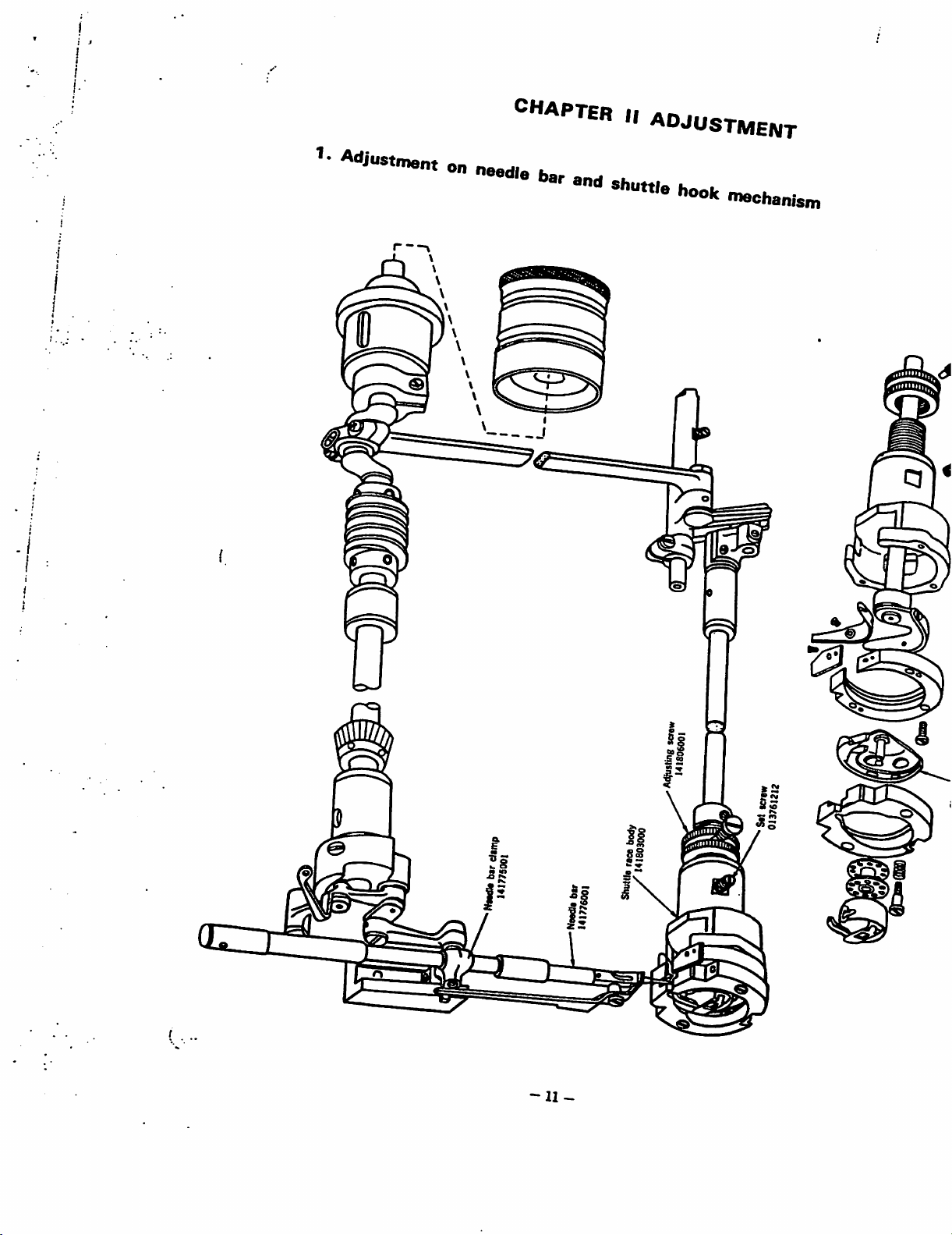
Adjustment
2.
Adjustment
3.
Adjustment
4.
Adjustment
5. Adjustment on
6.
Adjustment
7.
Adjustment
8.
Adjustment
9.
Adjustment
I
MECHANISM
shaft,
take-up
mechanism
trimming
nipper
clamp
lifting mechanism 7
mechanism
mechanism
11
ADJUSTMENT
on
on
on
on
on
on
on
on
lever, needle
bar
and
hook
mechanism
mechanism 4
mechanism
needle
bar
and
feed
clutch
work
thread
safety
thread
drive
bobbin
shuttle
mechanism
mechanian
clamp
mechanism
trimming mechanism 22
mechanian
nipper
mechanism
mechanism
winder
mechanism.
hook
mechanism
1
1
2
5
8
10
11
11
14
16
20
26
28
31
32
CHAPTER
1.
Thread
2.
Thread
3.
Clutch
4.
Feed
5.
Needle
ill
TROUBLE
tension
trimming
mechanism
mechanism
bar
and
SHOOTING
mechanism
mechanism
hook mechanism 36
33
33
34
35
36
Page 4
1.
Upper
shaft,
take-up
CHAPTER
I
lever, needle bar
MECHANISM
and
hook mechanism
DiroctiantofoUto
ui^
.Wit
Hign
speeo
puoey i417B3001
141781001
Oscillating rock shaft
141787001
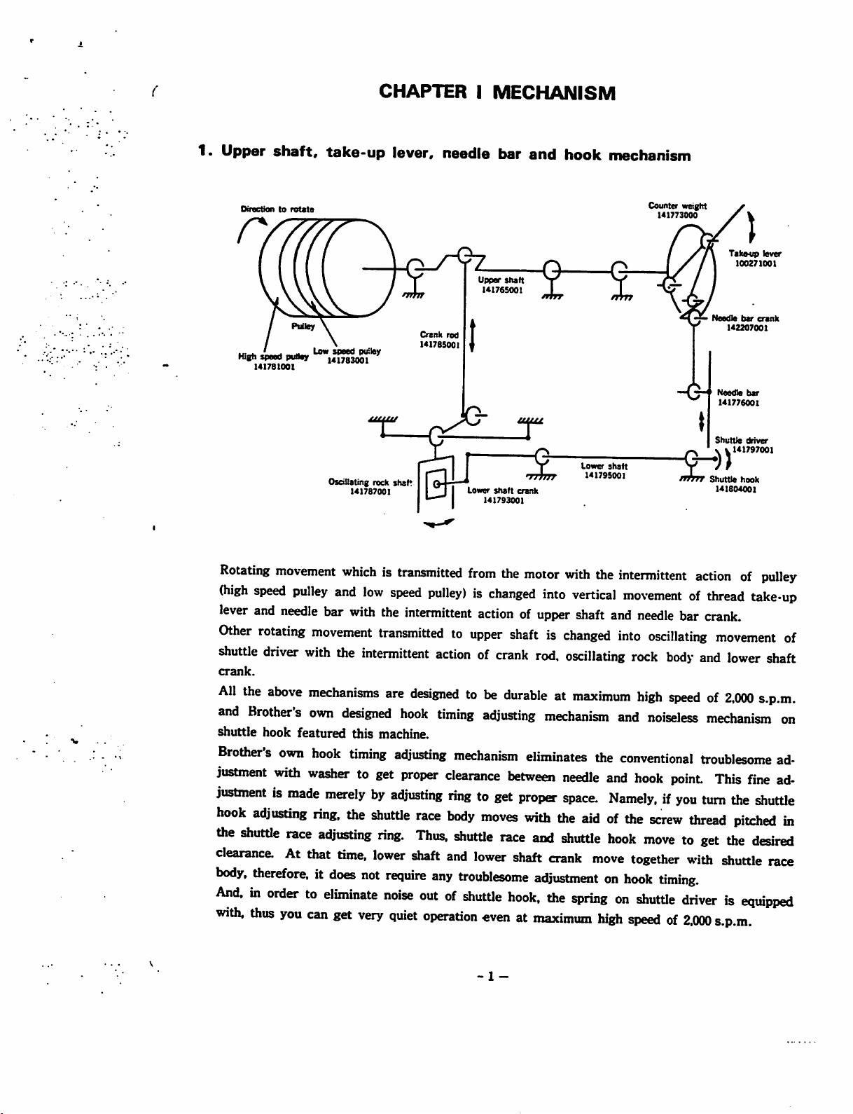
Rotating
(high
lever
Other
shuttle
crank.
All
and
shuttle
Brothersown
justment
justmentismade
hook
the
clearance.Atthat
body,
And,inordertoeliminate
wiUi,
movement
speed
pulley
and
needle
rotating
driver
the
above
Brother's
hook
bar
movement
with
mechanisms
own
featured
hook
with
washertoget
merelybyadjusting
adjusting
shuttle
race
ring,
adjusting
therefore,itdoes
thus
you
can
whichistransmitted
and
low
with
the
transmittedtoupper
the
intermittent
are
designed
this
machine.
timing
the
shuttle
ring.
time,
lower
not
require
noise
get
very
Crank
rod
1417BS001
speed
pulley)ischanged
intermittent
actionofcrank
designedtobe
hook
timing
adjusting
proper
mechanism
clearance
ringtoget
race
body
Thus,
shutUe
shaft
and
any
outofshutUe
quiet
operaUon
Upper
shaft
U176S001
Lower
sfiaft
crank
141793001
from
the
motor
into
actionofupper
shaftischanged
rod,
durableatmaximum
adjusting
mechanism
eliminates
between
proper
moves
lower
troublesome
with
the
race
and
shaft
crank
adjustmentonhook
hook,
the
«venatmaximum
Counter weight
I4I773000
Lower
shaft
141795001
with
the
intermittent
vertical
shaft
oscillating
movementofthread
and
needle
into
oscillating
rock
high
and
noiseless
the
conventional
needle
space.
shutUe
and
hook
Namely,ifyou
aidofthe
hook
move
together
screw
movetoget
timing.
springonshutUe
high
speedof2.000
Takotip
lever
100271001
Needle
t>ar
crank
142207001
—'
Needle
bar
141776001
Shuttle
driver
141797001
fftfTT
Shuttle hook
141804001
actionofpulley
take*up
bar
crank.
movement
body
and
lower
shaft
speedof2,(X)0
s.p.m.
mechanism
troublesome
point
This
turn
thread
with
fine
the
shuttle
pitched
the
desired
shuttle
race
driverisequipped
s.p.m.
of
on
ad
ad
in
-1
-
Page 5
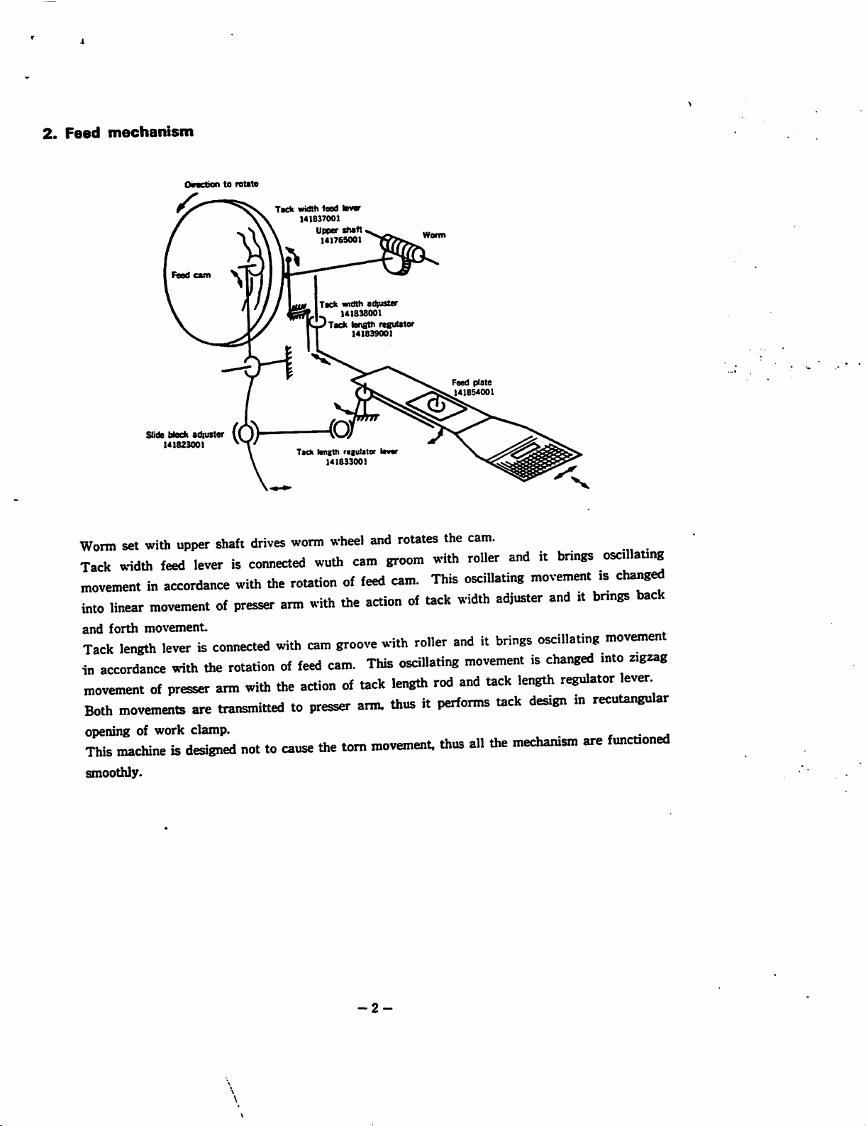
2.
Feed
mechanism
Oiractiontoretite
Tack
width
(^
141837001
teed
lever
141765001
Tack
width
141838001
K«_i<rTack
I
aQustar
lengthregulator
141839001
Feed
plate
141854001
Slide block
Worm
set
with
Tack
width
movementinaccordance
into
linear
movementofpresser
and
forth
movement.
Tack
length
in
accordance
movementofpresser
Both
movements
opening of work clamp. ^ ^
This
machineisdesigned
smoothly.
adjuster
14182300)
upper
shaft
drives
feed
leverisconnected
with
the
arm
leverisconnected
with
the
rotationoffeed
arm
are
transmittedtopresser
with
with
the
nottocause
Tack
length
regulator
141833001
worm
wheel
and
wuth
cam
groom
routionoffeed
with
the
actionofUck
cam
groove
cam.
actionoftack
the
with
This
arm.
torn
movement,
rotates
cam.
oscillating
length
thusitperforms
the
with
This
width
roller
anditbrings
rod
thus
cam.
roller
oscillating
adjuster
movementischanged
and
uck
uck
all
the
anditbrings
osallatjr®
movementischanged
anditbnngs
oscillating
length
regulator
designmrecutangular
mechanism
are
back
movement
mto
zigaag
ever.
functioned
-2-
Page 6
♦
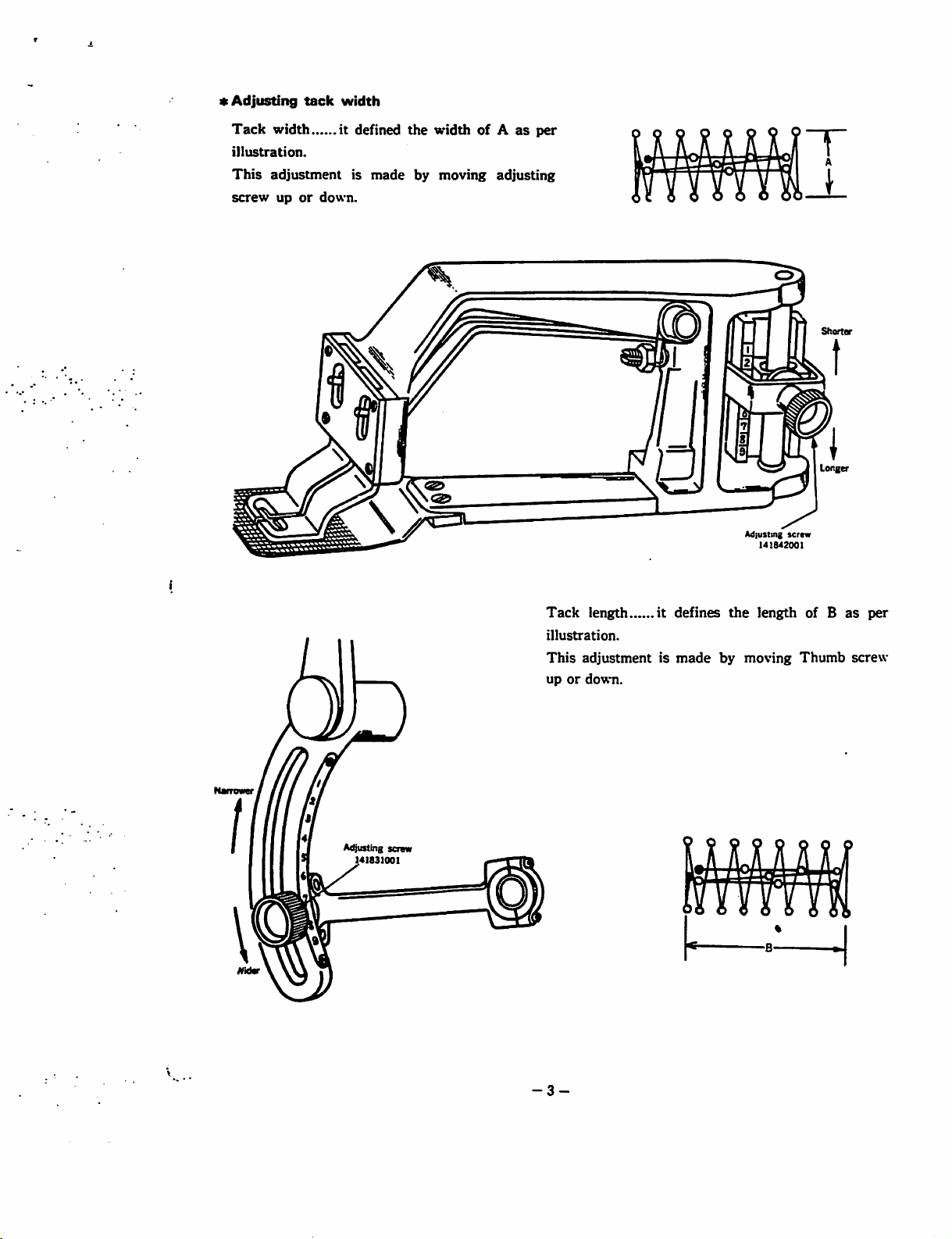
Adjusting
Tack
illustration.
This
screw
tack
width
adjustment
upordown.
width
it
defined
is
made
the
widthofAasper
by
moving
adjusting
Shorter
Longer
\
Adjusting screw
Tack
length
illustration.
This
adjustmentismade
upordown.
it
defines
by
Adjusting
the
moving
141S42001
length
screw
Thumb
of B
as
screw
per
-3-
Page 7
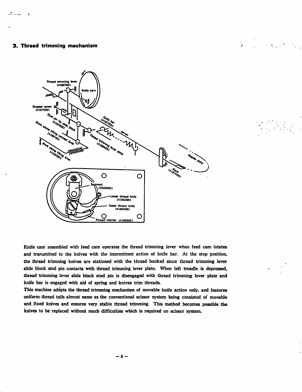
3.
Thread
trimming
Timed
trimffling lever
141867001
mechanism
Knift
ctm
105956001
Lower
Upper
o o
Thread
retainer
thread
141863001
thread
141864001
14186S001
kntle
knife
Knife
cam
assembled
and
transmitted
the
thread
trimming knives
slide block stud pin
thread
knife
This
uniform
trimming
barisengaged
machine adopts
thread
and fixed knives and ensures very stable thread trimming.
to
lever
tails
with
the
knives
contacts
slide
with
the
thread
almost
feed
cam
operates
with
the
are
stationed
with
thread
block
stud
aidofspring
the
thread
intermittent
with
trimming
actionofknife
the
thread
lever plate.
pin is disengaged
and
knives
trim
trimming
hooked since
When
with
thread
threads.
lever
bar.
trimming
left
when
At
thread
treadle
feed
the
stop
trimming
lever
trimming mechanism of movable knife action only, and features
sameasthe
conventional scissor
system
being
consisted of movable
This
method becomes possible
cam
is depressed,
knives to be replaced without much difficulties which is required on scissor system.
-4-
lotates
position,
lever
plate
and
the
Page 8
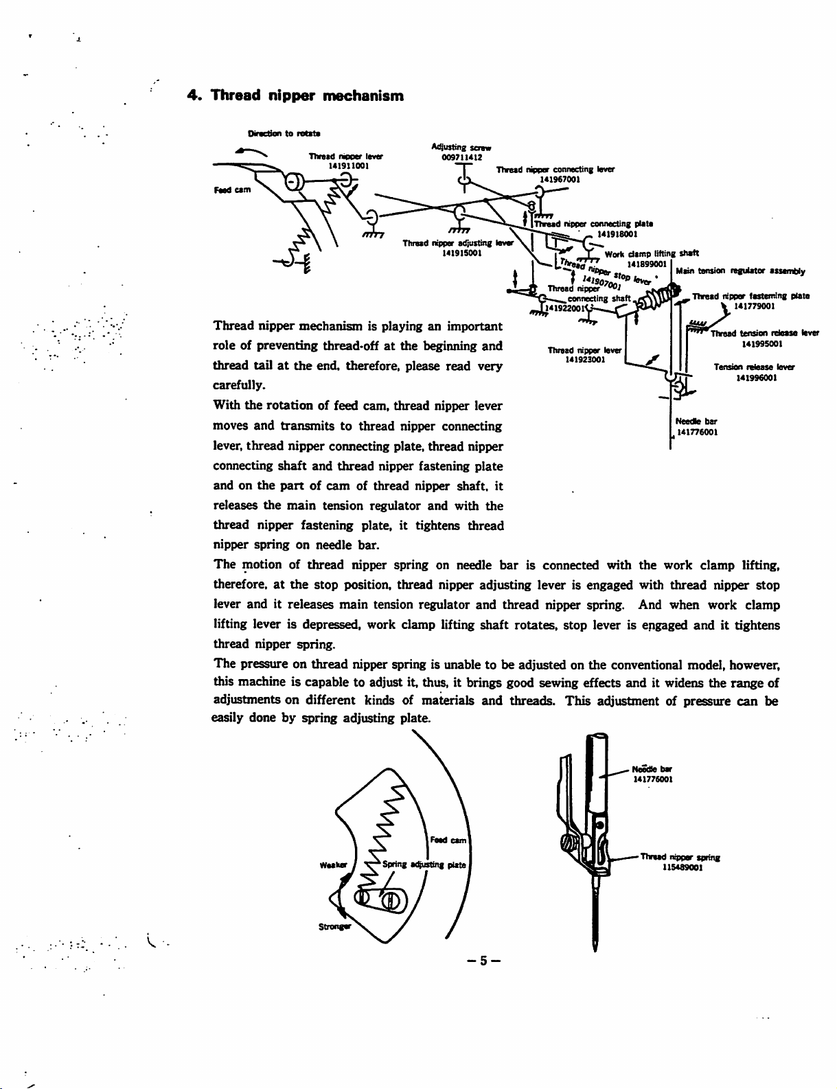
4.
Thread
nipper
mechanism
Oirvctiontoratita
Tlweed
Feed
cem
Thread
nipper
mechanismisplayinganimportant
roleofpreventing
thread
tailatthe
end. therefore, please
carefully.
With
the
moves
and
lever,
thread
connecting
andonthe
releases
thread
nipper
The
nipper
spring
motion of
therefore,
rotation
the
at
of feed cam,
transmitstothread
nipper
shaft
and
partofcamofthread
main
fastening
on
needle
thread
the
stop
lever and it releases
nipper
lever
141911001
thread>offatthe
connecting plate,
thread
nipper
tension
regulator
plate,ittightens
bar.
nipper spring on needle
position, thread nipper adjusting
main
tension regulator and thread nipper spring. And when work clamp
AcQusting
scraw
009711412
Tlwead nipper
adjusting
141915001
beginning
read
thread
nipper
lever
nipper connecting
thread
nipper
fastening
nipper
and
plate
shaft,
with
thread
and
very
the
connecting
141967001
Threed
lever
Thread
141922001
Thread
it
bar
is connected with
lever
lever
nipper connecting
O
..
nipper
connecting
nipper
141923001
141918001
Work
""l
shaft
lever
plate
damp
141899001
is engaged with
lifting
shaft
Maintension regulater assembly
Thread
Thread
Tension
Needte
bar
141776001
the
work
clamp
thread
nipper
nipper
141779001
fasteming
tension
141995001
relesse
141996001
lifting,
stop
lifting lever is depressed, work clamp lifting shaft rotates, stop lever is engaged and it tightens
thread
The
nipper
presstire on
spring.
thread
nipper spring is unable to be adjusted on
the
conventional model, however,
this machine is capable to adjust it, thus, it brings good sewing effects and it widens the range of
adjustments on different kinds of materials and threads. This adjustment of pressure can be
easily done by
spring
adjusting plate.
release
lever
plate
lever
rwd
cam
Spring
trusting
Waakar
Stnngir
plate
-5-
Needle
bar
141776001
Thraad njppar spring
115489001
Page 9
1
>Tt>wd
tonsion
141922001
Main
Pin
115599001
faradwt
tension
Thumb
117457001
regulator
screw
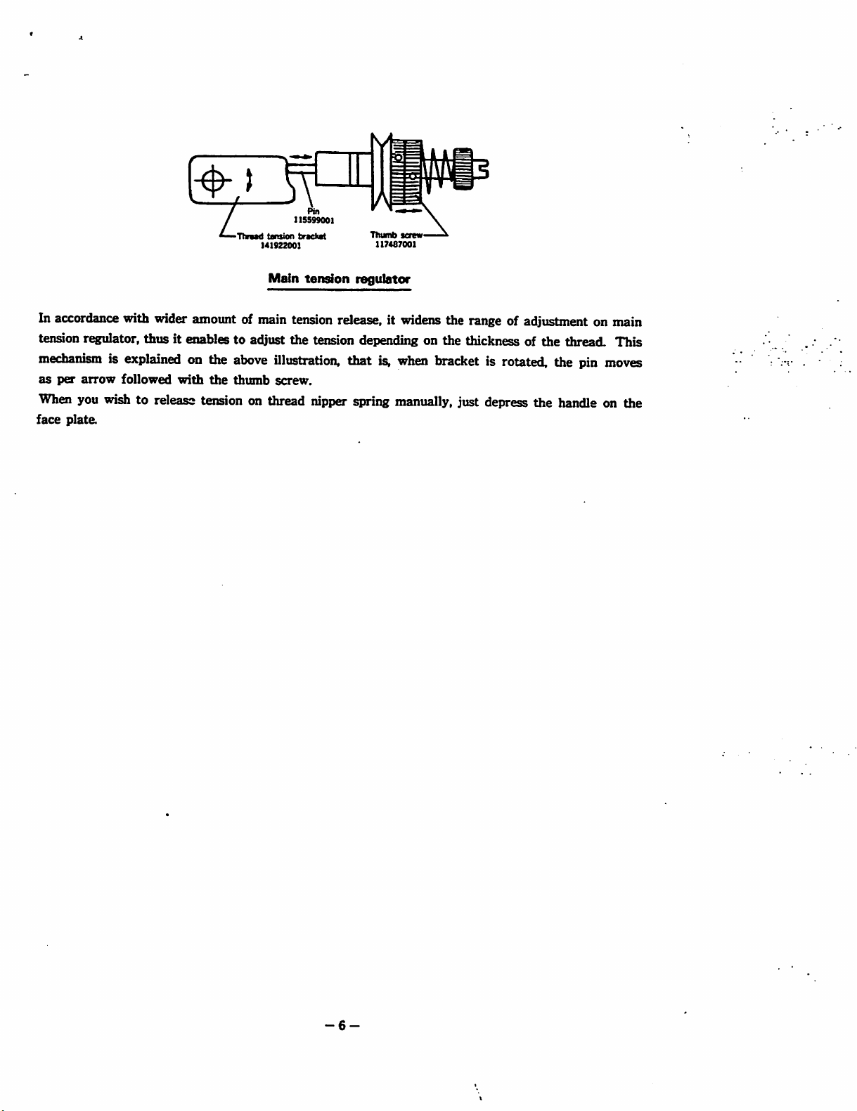
In accordance with wider amount of main
tension
mechanismisexplained
as
per
r^ulator,
arrow
followed
thus it enables to adjust the tension depending on the thickness of the thread. This
on the
with
the
above
thumb
tension
illustration,
screw.
release, it
that
is.
widens
when
the range of adjustment on main
bracketisrotated,
the
pin
moves
When you wish to release tension on thread nipper spring manually, just depress the handle on the
face
plate.
-6-
Page 10
'•
'<1881001
_
»
"^chanl
K ant)
'<1897001
(rufi
ism
*'•
tfaotp
J
J<190000,
sh«f»
ft
f'^ono
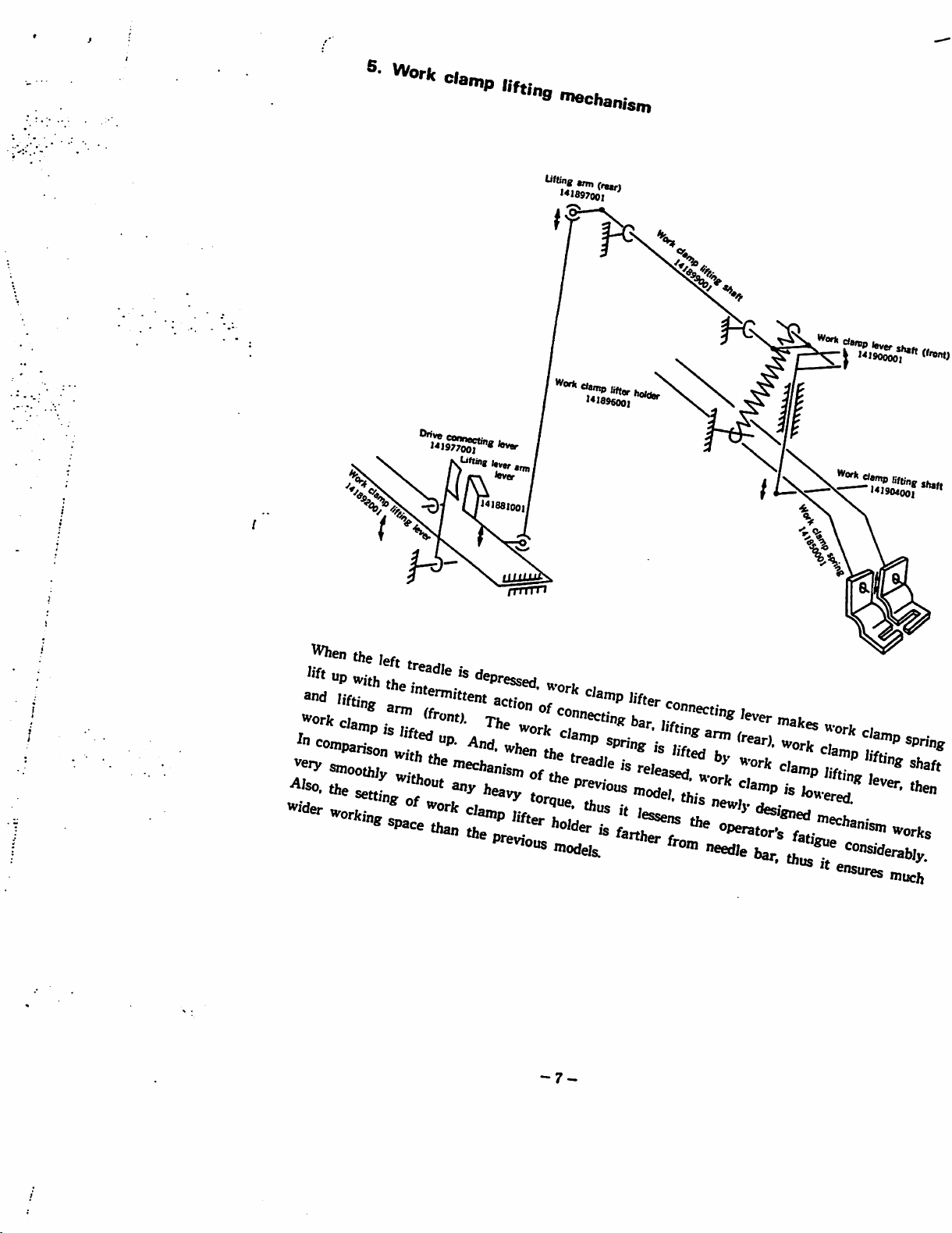
the /eft
h'ft
Up
Z'Z!
•"
smoothiv
®adleisdepresseri
h t/ie
fnfni
I..-
«,•
L ^ of
r>'
11''
^®cd,
to
n'orJc
fi,
/»!«
^
'
Z'™
^®'eased
ti
-"odr^.
ti""
*^'anip
' »
%
/jft;-
We?
't
ensi
-7-
Page 11
6.
Clutch
mechanism
Qutch
11S54S001
Brake
lever
141954001
stoppv
141782001
Ouch
144427001
lever
141783001
141962001
c
v-"^S^
Outch
tnppcng lever
141961001
Drive connecting lever
141977001
Food
cam
Clutch tripping dog lever
Outch
cam
[frrrr
141970001
lever
stopper
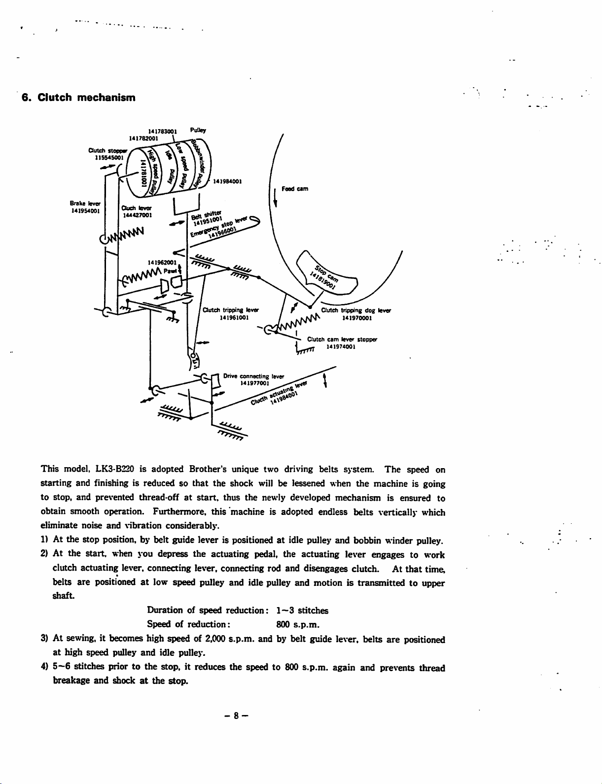
This
model, LK3-B220 is
starting and finishing is reduced so
to
stop,
and
prevented
adopted
Brother's
that
thread-offatstart,
unique two driving belts
the
shock will be lessened when
thus
the
newly developed
system.
the
mechanism
The
speed on
machine is going
is
ensured
obtain smooth operation. Furthermore, this machine is adopted endless belts vertically which
eliminate
noise
and
vibration
considerably.
1) At the stop position, by belt guide lever is positioned at idle pulley and bobbin winder pulley.
2) At the start, when \'ou depress the actuating pedal, the actuating lever engages to work
clutch actuating lever, connecting lever, connecting rod and disengages clutch. At
at
belts are positioned
shaft
3) At sewing, it becomes high speed of
at
high speed pulley
4)
5—6
stitches prior to the stop, it reduces the speed to 800 s.p.m. again and prevents thread
low speed pulley and idle pulley and motion is transmitted to upper
Durationofspeed
Speedofreduction:
and
idle pulley.
reduction;
2,000
s.p.m. and by belt guide lever, belts are positioned
1—3
800
stitches
s.p.m.
breakage and shockatthe stop.
-8-
that
time,
to
Page 12

(
before
the
endofone
cycleofsewing,
when
tripping
dogisover
the
stop
aun
sewi
Wing
cycleiscompleted
5)
Emergency
When
you
emergency
^
i""
stop lever
depressed
stop
emergency
lever
plaj«
and
machine
same
automatically
stop
lever
roleasmentioned
'='"^
pulley
down,
^tch.
thus
and
idle
puUeybybelt
stops.
tripping
above,
dog
thus
clutchisengaged.Atthat
guide
lever,
whichisassembled
machine
stops.
with
thus
I
-9-
Page 13
7.
Safety
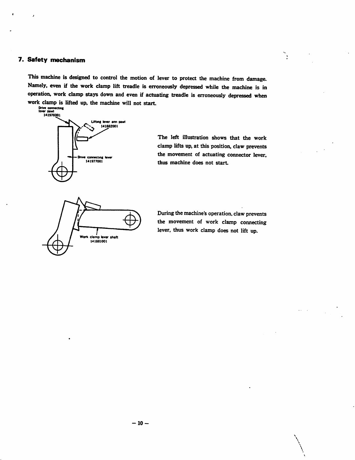
This
Namely,
operation,
mechanism
machineisdesignedtocontrol
even
if the work
work
work clamp is lifted up.
Drive
conoKtinc
tmr
PMt
I4I976001
clamp
Dm*
.C''..,
Worli
clamp
stays
down
the
machine will not
Liftni
levtr
141882001
coimaetng
141977001
clamp
I4I88I001
iavar
lever
the
motionoflevertoprotect
lift treadle is
and
evenifactuating
aim
pawl
shaft
the
erroneously
treadleiserroneously
depressed
machine
while
from
the
machine
depressed
start.
The
left
illustration
shows
that
clamp lifts up.atthis position, claw prevents
the
movement of
thus
machine
does
actuating
not
start
connector
Duringthe machine'soperation, claw prevents
the movement of work clamp connecting
lever, thus work clamp does not lift up.
damage.
is in
when
the
work
lever,
-10-
Page 14
O
X
>
u
X
>
c
»
ra
I
O
3
3
O
o
a
cr
tt
•I
a
3
a
>
O
c.
C
CO
-I
3
m
X
H
«
3"
e
o
0
1
3
5.
»•
3
damp
b*r
MI775001
btr
•<1776001
Neada
'•CObody
141603000
scfow
141806001
^sting
teraw
013761212
'Sti
Page 15

MowupBnp
•nd loft ond rigfit
down,
Fostening
Shuttle
ract
Shuttle race body
(1) Setting shuttlo race body (clearance
between
When
the
three screws so
ween hook point and point of shuttle
driver spring may be 0.3-0.5mm both
up
setting
position
and
doiKm
hook
and
shuttle
shuttle
of shuttle race by
that
positions.
drive
spring)
race
body,
adjust
setting
the clearance bet
(NOTE)
Hook point
In this
This
body
Shuttle
case,
remove
assemblingisrigidly
except
hook
unavoidable
down
position
—-
needle
from
done
needle
when
bar.
shipping,
thusbesure
necessity.
sh«tle
hookupposition
U1798001
0.3-0.5
Shuttle
hook
0.3-0.5
Shuttle driver
(2) Adjusting lower shaft play
When
matching
setting
with
shuttle
the
driver,
grooveoflower
firstly
And, set collar not to have play of lower shaft
(NOTE)Inordertoadjust
holder
and
heightofneedle
easily
shaftiscorrespondenttothe
therefore,
instruction.
please
make
nottoremove
Press hook lightly and turn
high speed
and
between shuttle hook point
and shuttle driver spring.
141757001
pulley
check
fasten
shaft,
the
by hand,
the
clearance
the
then
positionofslide
bar, the
diameterofsilver
sure to
follow
shuttle
silver
black
race
screw
screw.
block
grooveoflower
screw,
the
above
-12-
Page 16

(
he,
®«
SCTBW
slight,^
,ia#
•*"''»
^
'®*ver
H7,e„
..
axfe
. neecfJe '«
fcoot.^..
orWJ"^
Pofat
"osiOon^
si,^^
"
"te
c/ea^
^^fter
^ompI^
'"'^o
^ion.
bet»a^
fasten
neeaie
®ecureK
«nd
SCr«vtr
^nd
and
hoofc
^ooJt
'"otate
POjfif
Ponit
adjusfj
b€
Page 17

fo
6
3
O
3
r*
O
3
Hi
O
O
a
e
3
3-
o
tt
3
5*
3,
Marking
cain
raad
levar
regulaler
141838001
width
Tack
levar
feed
width
141837001
009821612
Tack length feed
141827001
bracket
Tack
sr-ew
141839001
I4I82300I
screw
Thumb
wMth
regulator lever
141855001
Feedregulator post
I4I83800I
Tack widthadjuster
justing
141842001
I4IB4400I
Tack width teed iavar bracket
141829001
Tack taflfth rod
Tack length regulator lever
I4I833001
Tack length legulator lever
141846001
ami
Prtsser
_ ^^Ticfc
yms
Work clamp
1
screw
head
Rat
Feed plate
I4I85400I
V.
Page 18

to
to
esign
>n
regulatedbyfeed
centre
(1)
and
12)
Adjusting
f ^ ^ "
tack
length
e
outer
and
mustbemade
work
clamp
swings
Adjusting
Feeding
matenai
down
quired,
bolts
Turning
advances
beginsasthe
into
loosen
and
turn
feed
the
vice versa.
tack
and
Uck
width
mechanisms
inner
groovesoffeed
within
the
and
even
when
adjustment,
mustbeaiwajisatthe
timingofneedle
neeeie
and
finishes
the
materials.Ifadjustmentisre-
worm
feed
caminits
timingofneedle
width
before
wheel
cambydegrees.
rotating
movement
cam.
rectai«ular
their
swings
the
positionsoftheir
same
and
feed
raises
outofthe
needle
shaft
nut
direction,
and
feed
transmitted
with
The
tock
opening
are
point
cam
comes
and
set
it
cam
105844003
Set bolt
017782012
Fieed
ca
Adjusting
Make
adjustment
the
coirect
Firstofall.
1)Utthe
Match
loosen
3)
Loosen
tack
4)
Loosen
bracketsothat
then
5)
Loosen
festening
be
the
flat
adjusting
width
feed
tighten
tack
positioned
tack
width
and
firstlyontack
adjustment
adjusttoget
first
needle
openingonfeed
head
regulator
bracket,
fastening
width
screw.
exactlyatthe
was
correct
come
screwsonfeed
screw
lever
fastening
the
needle
screw.
lever
Again,
tack
ion,,.!.
width
movemenraLlT""^!li™'^'^^
made,nofur^^TI
position
down
plate
plate
and
raise
shaft
screw
hole
fastem„g
move
presser
beTwLrwrk
into
the
needle
and
work
and
vet
hingehiiTT!
and
tighten^adLV
^ ^
is
screw
and
arm
centreofwork
work
.
L''
hole
clampInc
'' "
in
u-
andZ
elamo
Clamp,
Z
then
""""
'''®
tighten
sensible
and
with
^
openings
^
of
work
fastening
screw.
precise
great
areindisordi
cauth
care.
clamp,
0
'
ar
"8^'®
-15-
Page 19

. I
"
hole
clutch
with
»-
he
consumed
machine's
'essened.
easeofadjustment
mstructions.
for
durahility
and
tn™
Uck
I
them,n-
j . .
1.
he
i
"'*^^0
*"*
pulley
by
"ej'
""^"on.
considerably
follow
or
the
-
r-
/
''
Clutch
^'^•-'hepos.t::::;t,'^««^«op.a.ch
end
lever
cateh
tte
minimum
clutch
stopperisalv,
Insert
T '
_.
distani
'^3hlX":r-^
enm
that-brake
Stop
cam
shTri^"^"®'"
rid,
^
""h
-erd
thete
from
-16-
Otrtch
1'5545007
eo
earn
stoppor
«0P
trtrt
'/1962001
HK
'♦J950001
ctcti
1^1207001
lever
Page 20

r
"«nove
"""""""e
"Mt
^°''
the
can,
of
">«
tte
"»e
Ptd/ej,
ad,
belt
6el,
ad
u""
'ace
"o"
'*'"
®«
at
1
H
^27^
ffi
'Clutet,
cam fcvw
'*'9'40oI
Page 21

Clutch
3»
Adjustliig
(1)
Timingofstop
and
Please
so
latch
"aches
Ctuctfi
r
levar
catch
'41959091
nop
clutch
stopper
adjust
that
clutch
may
disengage
three
stop
latch
141962001
o
position
cam
stop
cam
stop
"'c
Action
wheo
tri^
^th
clutch
lever
one
stitch
endofsewing
^'s
case,
'^t
clutch
'^nll
disengage
clutch
within
position
groove
tails
"»ove
lever
±30-
of stop
into
stop
h'Sh
where
line
cam
catch
before
please
stop
from
speti
the
cycle.
see
latch
with
catch
the
the
cam
with
leftornVht
or
pulloylyhoni.
In
clutch stopoer
f
ngijttoadiusL
ridh.to,«nt
-IS-
t»*
A.
^
a""toBet
an
screws
proper
'staniry
tuning
serB»
and
by
Page 22

®
PoMtiono,em.
^
«PPing
pos.«„„
adjustby|ooc«
sere.30r™""f
'^'ween
rfce^^""stance
•
'astening
®™ergencyst^'""'a
Imm.
is
about
"«
and
®/"p
few
><i96sa
Preasuna
Adjust
i°
permit
•^a'ii'ely
aamtostopthe™
«a®Of1.
fastening
angleofspr/e^
! ;
®'
Prossute
a'opper
.'^•^'-nn.
•a
Position.
"•
»n
'P"ngistoo
noodle
">®
materiale3~"''"P-n
going
the
impact
Machineatthe
increased
advetsoly
»« .
«'«ch
.1
tPst
clutch
it .ill
„t
clutch
into
the
sere,
^"-""aiing
of
«♦„
^'PPersMngA
spring
;
may
to
„
" at
other
c
stro
ev
and^•
0^^
^
"
"-is
leue,
leva-
.
"apnog
'"""8
sT'*'"
"""'"'"'aP
"enti,.
'°°aen
'''ange
plate.
"
P'nachino
Wrong
"""P®-
'®nsion,
on
the
"•
«'
the
so
115S5S001.
2
"195900^"®
M
fewer
sor<„
machine?"'Ability
tJ^""
^n^nuts
^"p«
adjusting"
<
stoppet^"^
pn
®
measured
from
„„r
®
"«
in
°~'2mm
Of
Shaft
at^usting
,5^0®
Page 23

*•
on
work
clamp
fnechanism
8
-20-
Page 24

4i(
"''enOie
®'"PPer,
P/ate
0 p.
^dj
fo be
ositi.
a«,as,
on
Of
the h •
J0~.
Pim
^
«et
"fenip
Oftn
scre».
ft..
^
^eed
«"<»
n
'®'8'ner
tbr*
ead
cba/
'"S^a
Peed;.
3;
^•Vuse,
Str,
"•eat
^®Qu/ret/
'•CQu/r
,-.
's
^iper
Oie
.„ . •"
thread
Case
aure
that it
dtjg
the .
<ng
and
^'"P
red
^
Pase
""-aad
that
thre
""•®a<'
"t^Oirr
cfoes
Ore
oo
,u.
is
^
fO
D/a
^c&'us
Z'"''®'"'®"!.
i», .
®atf.
„
Of
up
vtrortf
"'
Ah
ro/e
"Pt
Up
ead
Of
'^'«S00to|
a
(
Page 25

B.
Adjustment
on
thread
trimming
mechanism
bracket
" ^
3)MsoonasAe
4)
5)
6)
i)
and
are
operatedbythe
upper
threadtoprevent
Thread
needle
Upper
The
^en^left
bar
(NOTE)Inadjusting
Setting
retainer
hole of
thread
machine stops.
needle
knife
Pssition
treadleisdepressed,
and
connecting
installed
orderonknives
releases
upper
threadispulledupby
plate.
enters
after
rod
spring
the
correctly.
and
'Thread
141865001
power
the
upper
the
thread
moment,
into
the
catching
knives,
the
pulls
firstly
Then,
thread
retainer
retainer
,Upper thread knife
141864001
transmitted
thread
from
just
before
the
pointofupper
upper
loopinthe
connecting
the
knivestotrim
remove
make
adjustmentinthe
from
knife
slipping
the
thread
thread
precessofforming
rod
needle
ii)
outofthe
fifth
take-up
loop
while
adjuster
both
plate
Relative
retainer
cam
needle
stitchisformed
lever,
lower
thread
thread
knifeisjustinfrontofthe
the
hook
point
the
final
disengages
threads.
and
following
measurement
and
from
make
order.
knives
sure
eye.
knife
comestoits
stitch.
the
tipofknife
the
between
PWO"
stud
"tshss
catches
knives
are
thread
the
140023001
ii)
Relation
retainer
between
needle
Lower thread knife
141863001
hole
and
Upper thread knife
thread
reuiner
-22-
NeedeXhole
and
knives
Lower
thread
(D
knife
Page 26

II
Adiu«i„fl
When
b«.ee„
bl.. b«w«„
you
set
se^en.
needle
plate
,„d
O^nunby.u™i„g
backwanl.
(NOTE)Incaseoftight
be
smooth,
wrong
Threfore,
thusitcauses
thread
trimming.
adjust
meet
,33.^
bite
between
the
bitetoget
timm«
^J Tl I k
wy,.nt
that
slight
and
needle
hit"f
play.
'•«'
^
'»
n.ckispositionedateither
o
••
"""'f®
bar
"teiner or it
^dius.
*«
forward
"-n
will
causes
U.e
or
imt
thread
(1)
(2)
(i)
trimming
Setting
At
above
•e
of
ower
markofneedle
Knife cam a
Adjusting
ttree
n
positionofrack
thread
the
recess
the
second
thread
thread
timingofknife
Knife
cam A
Raise
clutch
band
and
rising
eck
needie
trimming
loop
will
trimming
trimming
get
km'ves
not
^aseofadjustment,
sorew
for
knife
bmingbymoving
(»)Atone
stitch
»™' «ta.in9
lever
roUerisjust
portionofknife
stitch,
andatthe
knives,
knifeispositionedatthe
plate.
camAand
and
turn
driving
roller
positionedateach
pointsofknife
Bill
not
touch
and
the
touch
with
loosen
camAand
leftorright
before
the
cam.
stop
position
the
point
Knife
cam B
B
pulley
camA.and
with
thread
upper
thread
kraves.
fastening
adjust
final
the
stitch,
In
of
that
of
red
by
fastening screws
Tinnng nwrk
•Wfe
bar
Knife
guide
tiar
plate
(A)
cTtartt
./
I \
-23-
frmn
screwisstepped
Page 27

Jfstf.
6
6j,^
^case
^
7C^<>"
^(ti
<*<>«%,
^"of
*^tntt
^'"Sd
or
'^«Ss
h
'^^<i°",''.^"'">-aS
'H
'^arj^
0/
^Oetfj
'""fa
'"V
,.
'^*'0.
«»<#
^oo^''"^"t
^"'Vos
Vr
°'^
^a/^e
es.
fte
ae</
ti,n
-
^**ses
«&e
A
a/icf
'^ajA
is
- "
^'^'tion
Of
i'G(f
^ ^
.
fo
•'asf
^
^ef
..
Of
tin,.
®%rr
evi
'eij^
^'ajr
'Set
eaj
«ft,
o«
''"
Poin^'^ci.
^es
^'es
« ^
fo?'
at
fA
®"'
irt\'.r.
/Sfe.'®V
'®'Oer
«'•or,V
«'t6,
'e/,
"«/ „
ess
a/tf
Oof
t6e
ii
Or
e«„.
"ot^"kl
0/
^
^^ore
«Ch
ew
'^osiy.
'Oft
'"^'ar- "'"a.
'^A.e.r'
afe
f6e
^earf
'-
^^^as.
> /e^r.
Oj-
eacj
tC tbr^
•<ea<y
iij
^
fii
ffta/
s«
•^e ^
23
6jr
°Oeti
^e
3
So
StOff
ce
«Ch
OfSi
en.
'a
St
"">
Page 28

0^
^en
bite
Art
'*9
''°''needfe
betM-
bv
t
biu,
segn,
•on
meet
•»«'
fScIt
'^rks
^bovQ
mar/
(t^OTE,
ax-ead
aier
i,
be
^'""'-ck
*n//e
®'"'®«>.th~
a-read
'ev,
/er
a«
&
We1""°"
'^x-een
'•'
=»>«as
*&n/j
'tg
Of
holler
IS
Jusf
s.oaT':»«
of
red
*'•'5
'•Sfl
6nf/)^
kn/-
»ves
*C»1»S
a,
^ead
eijt
of
retai
««"«»,
I
'
Or
<:.
««
its
f/;
c^sec,'
acreur
«„.
4/^
""e
^ben
^Shest
fftree
^ ^
cfceck
„
•*«
need/e
majiogj^
*17;
'"•A'cr««• ^ h
o/^'"'""®''atea
.,-„
not
„
eoac»
r
'»'"
iiUf.
aiient
i
'°°sen
movLT^a</^
a/tri.^'®aorri
befo..
SCTeur
rore
the
thn
®sa
tafc
ad,a«':i"'"'
stud
'
*«%
tc^
the
ftia/
the
cam 4
cam
tkrcad
^mVag
/V
«f;tch.
'evart.
on
23^
Cam
a
and
3
t''
/
4.
and
^ead
.
^
aie
is
Posjrt
of
Oiled
^oife ^ the w
^thi.
Of
^OlIU
Page 29

««)
,
kooks
Knife
At
downatthe
lower
cam
B '
the
final
first
recess
thread
stitch
nnr*-
adjust
h
knife
camB.Thisisthe
timi
^'""a-
s
thread
knife
fkn
(NOTE)
^asteniRff
«cr«w
3)
Positionofthraaii
'kt
the
stop
ootnws
n-insting
'o»er
and
screwsodm,
thread
When
roller
isT
in the rangp nt v
---
rangeof90-^135.'upper
-on
"tead
position,
adjust
knife
Of
km-fc^mT
m
tnmming
lever
loosen
J°T
'
plate
»
•"
-^0
k^fr^iTTt^r
(NOTE)
these
as
to caiieA * ®e
°
wachet set screw
-
o^dot:
that
you
cams
evenlyonth. t
unusual
(tavelling
thr^^T"
1fs:::
may
rotate
noise.
«"«'n»that
down
••"
second
knife
recess
cams
in
red
markonneedle
When
work
clampisHftg^
otopper
'™™'ing
about
0.3mm
cam. knife
At
this
"oedie
of
Plateispositioned
upper
scre^
lever
roller
from
moment,
thread
kmfe.
so
the
the
pla^
may
be
bo«
needui,i
at
tie
-24
®-3fiwi
-
•««f8nces
Page 30

/ '! •
-»
•aiistng
•o
work
loosen
Adju«i„9
katfe
^ m
<in»e
tewtonofkrtfa
bar
puHfeg
kni«s
some
breakage.
the
Often
extreme
fcmves,
B „„ ,k
thus
smoothly.Toa<Bust
set
left
screw
orright
,„s
fail
to^rT
cases
the
the
h.
•»'
PuBns
colivi
^ c
opriiv
J
^
«ension.
o<fiusting
Stopptf
Knifebar
Ming
spring
c.
-25-
Spring
adjusting
bgy
Page 31

§
I
3
O
3
O
at
3
«
o
•<
»
a
3
5*
3
(rear)
142433001
Jobrt
icraw
arm (rear)
0097II4I2
Lining
FaKenIng
141897001
patvi
arm
(ever
141882001
Lining
pawl
lever
141978001
connacllng
OHve
lever
I4I97700I
conneellng
Drive
141881001
Lining lever arm
bar
MI98300I
connecting
Drive
I
I
Page 32

tte
mach.„
.
njachin^
tten
wrorfc
fe
case
Of
.
«.
Se^tt^r
'®'
(
the
»
i. ^'nnifn» i stai^ h
cJa
«p.
tottow0^,.
-vet
ri
^
,etV^.
®"»"er
«,. .
a..
in„
tfcread
"ncwiipg
tobe,•
tP
,.
f"'^Ceo/^
""•"«>•««
"""
„/ ^
^
the
o,e^'
„ „
'eft
'""•
t,^,
to
«»
(41
r '^•>8
Just
befnm
oefore
hft/iig^
a^
the f„ .
''machine
C;'""
-"'^".ad
Shoe/
arm
ston«
"e
<C^
"""""'et.
, ^
'ever «, .
"•«
''"'ve
the
re^:,'^;
^27
-m
Page 33

C
(0
eO
3
I
e
a
9
9
a
a
V
3
9
O
a-
9
a
3
S'
roOar
lavar
141923001
nippar
Thread
Collar
HI90800I
0097II4I2
re^ustlng screw
lever
oparallng
I4I90700I
Nippar
lever
connecting
"'96T00>
""PP®"
O
t S
levar
7
adjusting
I4I91S00I
adjusling
nipper
nipper
Thread
pawl I4I9I000I
Thread
•ever
shalt
connecting
141922001
nipper
Thread
plate
fastening
I4I92300I
nipper
Thread
plate
faitanlni
Nippar
I
I
141779001
spring
nipper
115489001
Thread
Page 34

'"Pper
^alre
"*)
P
'ts
P
the
^eed
'^ast be
^n
cae
'••"e'e
"^aadnm_
need;.
n
'"eg.
/e/(
the
n,
to
"^'•n
'oop.
the
lipper
eye
and
ased
be^
and
nia/n
/s
'•e/e.
a<0'ustn,.
nnftfenof
the
«<>p
P0s,t/„
""I
bo
Of
""Oad
"^sition
Cam
the
O/:
"'PPer
bei
rd."'
"'•'"e'nient;*'^e
a^pper
•
'aosen
w""
"^«sion
'®
tfen
._
'^®'®ase(f
's
fie/i
''"er
roller
p .
trith-'^'"•nn
'•ed
niarh,
®Ofin,
®®""9tev8.
ovg^
or^
fa«. .
"nnJ
®Wtch,
'^'ned.
'n^.
^nion
ca^,
So
Pin
the
^
that
^PPer
'••nes
ers.
«,«
do^
n>re^
'fcrepd
the
®®Coin#
mt
frof
'ev(
4t
this
«n./evert
«aged.ad,
--Cr;'
the
n'feed
canj.
^ P,
osftio,
end
at
case of
®crenr
Poiti,
"<""n».d
the
atop
'ension
nipper
efeft
>•
®®®n-
On
''OSltf,
"'PPer
'On
(befi
'eve71""
'oosen
Pos,d„„
recess
eani
tb
Porti
hft
on
'n»
aiust
"•«
nfepe,
PQs/ti
o//.
ns
fever
ivorfc
"'nmp;.
be
Positii
CO,
n-nd/d,
, ..
On
eed
<^ni;.
oned
°a that
aipper
of
and
die
luting
\
njfBa
OOflfl
"'•1
(
^2!9^
Page 35

4)
Adjusting
main
tension
regulator
At the position of roller being over the
that
thumb screw so
recess portion of feed
5)
Position
At
off
nippar
the
positionofthread
pawl being disengaged
lever,
moving
spring on
6)
adjust
left
or
needle
thread
securely.
Adjusting coUar ffor
At
the
stop
position, when
depressed, adjust
nipper adjusting lever pawl
operating lever by positioning collar for nipper
operating
lever.
main tension will be tightened and at the position of roller being in the
r-am,
adjust it so that main tension will be loosened.
thread
rif^t
ffastanlng
nipper
bar
nipper
the
plate
nipper
adjusting
with
nipper operating
fastening
so
that
thread
may
catch
the
operating
the
left treadle is
bite between thread
and
reces^
lever
plate
nipper
upper
lever
nipper
a
••
portion of feed cam. adjust tension adjusting
Tension
dtet
108721001
CoOv for nipper operating lever
141908001
Set
screw
014770622
-30-
Page 36

t
"""«»
!v°C"
«i
Sr.-"
®S«
••SO
e*P/afned
adiust
etutet,
prevent
tt.
to set sr,
and
f„
due,0f
"'»«
.e,
''®®<"eisd
«««»,,
as
es„,
"Cn
°°®en
set
scr^
®
^'X'
.-t
causes
«.
/ I
""»-«
ievt"^
^
case
„r
'""•"siiw™
^"«ment,
"sventeTt
.*•
«>Bet? '
®f« ^
®
W)
Adi'
®'*<atnw
tten..
^®*^nein„
at
sto
I. 'Xsidon
..
'"
"teacces.
*a«e
oiitj
**^ssojy
-31^
in
1^
the
°'^
**««ine
/^fsSj^lOppar
tevtt.
Page 37

Ad,
Adi
In
'o'^Rr/i,
^I)
Put
Set
ont
ng
due
^
scre^, ,
On
c'otci,
"eit
^Oo
^ers.
cfr#
•"ecfca
•^fev,
/s
n,
Wsft,
'9r
®'"'esserf
tfce
.1 ^aus^.
<^onner^
<^ontu
ct
^'th
^«aa„,«-^
Set
Oie
er
'
screu,
niacft
5»»v
open
ii«e
'®°sa,
'oHrerfn
Out
»«oo;
^Md
®ir"'
"•Oust
^'asfB,
4/f-. ^ set
VPStfi
f/je
'^•«on
to
Cojjjnt
•"dtcii
"9
'".'"^«-tOB
^o/jjj»
®^eij(
feu,
er
®<"efrr
Of
«'aetoe^'^
^'•
acj/us^
Of
'13
®»Ciine
'ctua^a,
Screw
'••®SefrL'°'"®'nedin'^"^
ft;
tbe
•^'ust
^""".esiti
Oil.
ann
«s
eap,,.
... »
Set
/ever •
scre^r
ar^
'ever
nonne/
ajitf
i^'^.'^'-een
Set
screur
Set
"opper
/ever
o/otcA
t/ie
as
Screw
O'wfcft
^Oin
u,„
scn^
s^,
**W
'"«^ssr'
Out
set
Screw.
Page 38

Adjt/i
nt
Adi
b,
topper
««uatfn
4.
b)//<
"^'"P
(1)BeM.
®J=t,
Adfj
'^'e>s
^O//,
»>
Put
C2>
J?a•
Set
®^^«st
beef
and
•"«»»
^en
fasten
•^er
Con,
""*•"•
"-etto
tin
c,«^"f"^eacfle
tfte ,
Oi
,rf.
"tannc
'"^''
^ers.
/""^^sts,
aue
to
too
Uttch
s^,^^
®®
to
the
coQta/
-.1
"'''3'ned
®creT».
®®en
set
'^Ir.'"
®^eH^
C.2,-
'^"^"POver
Cfte
WU
oj
"" ""
<='>'tch
^<Uust
in
^^le
scTeur
"*
s_
scret^r
screur.
is
•niovi
,..
<^ve
iiietf
betvv»
as
**®PPer
'nj
tbe
'n/sin
'*'•<
/_
er
^bove.
and
^OtCh
•C|08,|
j7.
« fever
"•'^asooir
•'«£&»
bo> f
®'°few
O'-t/er
c»«,l''««ooi
*n»w
''eits
s//
''PP/
(S)
(3)
4i3ter
P'ain^
.
®baft
'•VVPH^^vvt
Out
Set
®creRr.
Set
(
-3J~
Oiitcft
««uafc
fever
'*i988oot^*l^
Page 39

9.
Adjustmentonbobbin
H
Adjusttng
In
caseofuneven
hsightofbobbin
Postnonofbobbin
2) Setting
presser
When
with
adjust
winder
endofspring
positioned
bobbin
positionofbobbin
bobbin
presser
bobbin
the
winder
positionofbobbin
paw]sothat
plate
at the
winder
centre
pawl.
winder
mechenism
windor
windingonbobbin,
winder
contacts
shaft,
the
top
may
be
of
tension
loosen
by
raisingorlowering
Bobtxn presser
Bobbin
winder
141755001
tension
*i«'ar
tansion
141756001
shaft
stud
collar
tension
guide.
Bobbin
winderpswl
11194S001
set
sZ
screw.
ZZ.
'Tensmt
stud
I18405002
, ^ .
coOsr
Spring piste
111942001
'
3)
gaged
pawl,
bobbin
rubber
pin
not
Sotting
prasser
When
and
have
positionofbobbin
stopper
spring
set the
presser
ring
with
may
bobbin
too
much
plateisdisen
bobbin
position
stopper
contact
presser
play.
wnder
of
sothat
with
may
presser
111950001
141752001
stopper
Builder ring
120448001
Pin
-32
-
Page 40

1.
Thread
1)
Thread-off
(1)
CAUSE:
ADJUSTMENT:
(2)
CAUSE:
ADJUSTMENT:
(3)
CAUSE:
ADJUSTMENT:
2)
Thread
tension
breakage
CHAPTER
mechanism
at
the
at
Hi
TROUBLE
beginning
In
caseofloose
tensiononthread
Refer7.Adjustmentonthread
Page
30.
In
caseofwrong
Set
thread
position
trimming
Page
22.
In
caseofshort
At
the
final
on
needle
the
machine's
of
mechanism.
bar,
positioning of
retainertocatch
thread
stitch,
retainerisreferred
thread
and
stop
end
set
the
functioningofknives.
SHOOTING
nipper
nipper mechanism.
thread
the
after
timingoftension
retainer.
upper
threadatthe
trimming.
springonneedle
to
5.
Adjustment
release,
theread
first
bar.
stitch.
on
nipper
The
thread
spring
CAUSE:
ADJUSTMENT:
3)
Untidy
lengthofthread
CAUSE: In
ADJUSTMENT:
4)
Loose
upper
tension
CAUSE: In
ADJUSTMENT:
5)
Upper
thread
jamming
CAUSE: In case of the upper thread not being
ADJUSTMENT: Adjust thread nipper spring on needle
In
caseofnot
Adjust
that
the
end
caseofthe
the
upper
Adjust
thread
case
Adjust
nipper
main
the
nipper
the
lever
being
loosenonmain
tension
proper
from
thread
knife
of loose
upper
rollerispositionedatcircumferenceoffeed
regulatorsoastobe
lengthofthreadispulledbyupper
needle
upper
thread
by
thread
timingsothat
springonneedle
main
thread
being
nipper
tension
being tightened by
tension
trimmed
spring
the
bar
tightens
regulator
on
knife
discs.
ti^tened
on
needle
baratthe
first
stitch.
barsothat
range of
the
needle being pulled out of needle hole untilatits highest
position. Loosened main tension discs will be
barisraisedupat
its
highest position.
regulatoratthe
loosenatthe
thread
final
knife.
final
stitch.
stitch
by knife before tightening
needle
willbeoperated
the
thumb
upper
bar.
thread.
screw
when
cam.
as
soon
thread
by thread nipper spring
it is tightened at the
Hghrpw»H
until the needle
so
as
c
-33-
Page 41

Th:
*0*1;
JJ,
^^VS£.
^Dju,
Off
^TAjp
Nt
•'
•Wecfca
t*»e
•61
p....
In
Case
'Cr
Wsm
•Mils
7
•
30
Of
^Oi
^ead
<3;
^^JVi
Arr-
'"BOflf
Offe
at
"I®
^dj
^oad
in
yust
in
sacf
case
/
/
/
"'"Ify
-'Ua
"PPet
L.
^toth
Arr
fhreaw®^ai/e
Oil
in
in
4t
t/)e
r=-
0/
M,
3fiie
22
case
0/
abort
bar
' atop
ttroo^""
*^^^Per
""ft,.
fr,
o*n
'^efib
the
^Pper
by
thft
f,;^
opting
On
thft
^
tt»0J
ea</
cad
^i<
J;»»«e
®iU
(•
VAer
C4t/se.
^jn
®rA££.
•X'T:.^."'^'
in
Case
an
^^Ust
aan^e
0/
thre
'Carf
Of th Sftw
'
is
^,
®®cned
the
uppg^
®t the Pot
„. ^"st
"eedle
i„.
"**
n, ^
^Xioi
33^
''a/w
lest
oej
«*•
o„
i>osif,-,
fja*
'e
^
0/
///
ose
On
thn
•
"^Of
to
""
o*snj.
tbre
""ead
ioni
he/j
«er
On
'^a/o
ator
®««''sn,.,.^'"osa,
Pu/;et/
tnnj.
aietf
that
^'Scs.
l^r
<Si*w'
"""nfcscn.
6a,
that/»-
aeoc^g
. ts
i»eft" ®
*«»td
o„
fens
on
the
untd
»
by
^
f'P/Jea-
»te
"'PBe,
"'Wn,
tferi
eacf
rerf
thft
"«>Per
the
PeetJie
®#IOo
^«niaa.
to
ator
at
at
the
hefi
Ore
as
•cad
^I'Aen
thft
at
tfc-
'est
at
4(fj
the
"sht
Soon
cad
tfie
fustn]
neatf
iina
enj
Page 42

2.
Thread
1)
trimming
Upper
thread
A
USE.
^
ADJUSTMENT:
mechanism
not
being
Wrong
Referto5.
tr&nmed
settingofupper
Adjustment
thread
on
knife
thread
trimming
mechanism.
Page
22.
AnTTTr-i-*
"•
(5)
CAUSE:
ADJUSTMENT:
2)
Lower
(3,
thread
not
being
^yUCTMTMx
^JUSTMENT-
rangeof90--135-
Wrong
.oosTng
Dull
Sharpen
positionofupper
:::reronr::
knife
edge.
knife
edgeorreplace.
trimmed
T""®
suuoISat
the
3. fte
first
of
final
sfitch.
thread
knife.
:=^i:z'z.r:z
rr.
recess
knife
'o"®"-
portionofknife
camAand
B.
cam
k-ife.
B
AriTT^e^
ADJUSTMENT:
(4)
CAUSE:
ADJUSTMENT:
3)
Needle
(1)
breakage
CAUSE:
ADJUSTMENT:
^JWTMENT-
JUbTMENT.
ADJUSTMENT:
weak
Adjust
Blunt
Sharpen
Wrong
bobbin
knife
the
settingofknifes.
RefertoS.
LT
Set
RefertoS.
T-
the
tunmg
tensiononlower
case
spring
edge.
knifeorreplace.
Adjustment
marks.
Adjustment
°°
(NOTE:
-34-
tension.
on
thread
on
thread
thread.
trimming
^
Make
sumonplay)
«
o"•'«"•-
trimming
mechanism.
and
mechanism.
position
if
Page 43

I f '
I
Clutch
1)
mechanism
Mal-functiononbelt
shift
Improper
ADJUSTMENT:
(2)
CAUSE:
ADJUSTMENT:
2)
Machine
does
ADJUSTMENT:
(2)
CAUSE:
3)
Machine
3)
M
)
Machine
^
ADJUSTMENT:
sj
irregular stop position
does
not
Sfrvntvx
JUSTMENT:
does
not
Proper
temporarily
Wroni?
Wrong
Adjust
and
Referto3.2)Adjusting
not
runettop
Change
Slippage
stop
r™"
Refertoa2)AdjusUng
runatlow
Wrong
Refer
lengthofbelt.
lengthofbeltis30-4ni«
between
•• ^
position of belt
the
positionofbelt
high
speed
pullevsoff
shiftPr
operations.
beit
speed
the
length
duetooil.
cotxectly
heightofclutch
speed
positionofbelt
to ^
aj-
3.2)Adjusting
shifter
belt
shifte
shifter.
on
Powl.
shifter.
i,
machine
the
upper
iever
Page
17.18.
head
and
Shaft
bushing
paw,.
length
the
motor.
(rear,
thatitsets
'»«'
(1)
CAUSE:
STMENT:
raCASUE-
ADJUSTMENT:
(3)
CAriQir.
adjustment
ADJUSTMENT:
6)
Abnonnal
noiseatstop
A^J^TMENT:
(2)
CAUSE:
adjustment:
(3)
CAUSE:
adjustment:
7)
MaMunctiononclutch
^11
^AUSE:
Wrong
Too
ReferTs.
Adjust
Tn«
Adjust
To« u .
cam
Wrnne*
positionofstop
1,
Tpr^e'of
belt
position.
t^ons
and
clutch
lever.
• •
shifter.
cam.
of
®
T •
Pressureofstopper
reduction.
stopper.
-35-
olwoh
spnng
A.
spthw
and
t
clearance
sto««r.
stopper
sprimi.
between
bulgeofstop
Page 44

(2)
CAUSE:
ADJUSTMENT:
(3)
CAUSE:
ADJUSTMENT:
8)
Belts
off
(1)
CAUSE:
ADJUSTMENT:
(2)
CAUSE:
ADJUSTMENT:
4.
Feed
mechanism
1) Needle breakage
Wrong
Referto8.1)
Wrong
Referto6.
Wrong
Adjust
Wrong
adjustmentonclutch
Adjusting
clutch
adjustmentondrive
Adjustmentonsafety
positionofclutch
position,
referto3.2)(2)
adjustmentofclutch
Referto8.1)Adjusting
actuating
actuating
connecting
cam
lever
actuating
clutch
actuating
lever.
lever.
bar.
mechanism.
stopper.
lever.
lever.
CAUSE:
ADJUSTMENT:
2)
Irregular
(1)
(2)
5. Needle bar and hook mechanism
1)
Needle
tack
CAUSE:
CAUSE:
ADJUSTMENT:
breakage
CAUSE:
ADJUSTMENT:
2)
Skip
stitch
(1)
CAUSE:
adjustment
(2)
CAUSE:
JUSTMENT:
Wrong
Referto2.1)Adjustmentonfeed
design
Wrong
Wrong
Referto2.
and
Needle
Adjust
adjusting ring.
Referto1.5)
Too
: Same as above.
Wrong
Adjust
line
as
Refer
timingoffeed
against
bending
work
centreoflength
centreofwidth
Adjustmentonfeed
hits
hook
clearancetobe
muchorless
timingofhook
heightofneedle
with
the
centre
standard
measurement.
to 1. 3) & 1. 4) Page
mechanism.
clamp
opening.
point.
0.03-0.05mm
clearance
point
barbyshuttle
axisofthe
feed
movement.
feed
movement.
between
and
12,13
mechanism.
mechanism.
between
hook
needle
and
driversothat
needle
when
needle
point
wrong
needle
and
bookbyturning
and
needle.
needle
the
bar
bar
hook
raisesup3.5mm
height
pointisin
3)
Thread
(1)
(2)
breakage
CAUSE:
ADJUSTMENT:
CAUSE:
adjustment
only
Scratchesonthread
Eliminate
Blxmt
: Replace.
oneortwo
thembysand
needle.
plysofthree
guides
and
paperorgrind
-36-
ply
hook,
thread.
etc.
stone.
Page 45

4)
Thread
(1)
jammhig
CAUSE
v-rtuon:
ADJUSTMENT:
(2)
CAUSE:
Adjustment:
Out
r •
A<(iu^
Wrone
M,
""die.
""
""d
thread.
I
(3)
CAUSE;
CAUSE:
ADJUSTMENT:
"
AtJ^
"PP"
du-ead
J"P
depending
„„
.^ZTZ
^"inteasure^ea,
spnng.
-37-
 Loading...