

Page 1
Brother Laser Printer
SERVICE MANUAL
MODEL:
HL-2030/2040/2070N
Read this manual thoroughly before maintenance work.
Keep this manual in a convenient place for quick and easy reference at all times.
November 2004
SM-PRN054
Confidential
Page 2

© Copyright Brother Industries, Ltd. 2004
All rights reserved.
No part of this publication may be reproduced in any form or by any means without permission
in writing from the publisher.
Specifications are subject to change without notice.
Trademarks:
The Brother logo is a registered trademark of Brother Industries, Ltd.
Apple, the Apple Logo, Macintosh and TrueType are registered trademarks of Apple
Computer, Inc in the United States and other countries.
Epson is a registered trademark and FX-80 and FX-850 are trademarks of Seiko Epson
Corporation.
Hewlett Packard is a registered trademark and HP LaserJet 6P, 6L, 5P, 5L, 4, 4L 4P, III, IIIP,
II, and IIP are trademarks of Hewlett-Packard Company.
IBM, IBM PC, and Proprinter are registered trademarks of International Business Machines
Corporation.
Microsoft, MS-DOS, Windows and Windows NT are registered trademarks of Microsoft
Corporation in the U.S. and other countries.
ENERGY STAR is a U.S. registered mark.
Citrix and MetaFrame are registered trademarks of Citrix Systems, Inc. in the United State.
All other terms and brand and product names mentioned in this Service Manual are registered
trademarks of their respective companies.
Confidential
Page 3

PREFACE
This service manual contains basic information required for after-sales service of the laser
printer (hereinafter referred to as "this machine" or "the printer"). This information is vital to
the service technician to maintain the high printing quality and performance of the printer.
This service manual covers the HL-2030/2040/2070N printers.
This manual consists of the following chapters:
CHAPTER 1: GENERAL
Features, specifications, etc.
CHAPTER 2: INSTALLATION AND BASIC OPERATION
Installation conditions, Installation procedures, basic operation of the
printer etc.
CHAPTER 3: THEORY OF OPERATION
Basic operation of the mechanical system, the electrical system and the
electrical circuits and their timing information.
CHAPTER 4: DISASSEMBLY AND RE-ASSEMBLY
Procedures for disassembling and re-assembling the mechanical
system.
CHAPTER 5: PERIODIC MAINTENANCE
Periodical replacement parts, consumable parts, etc.
CHAPTER 6: ADJUSTMENTS AND UPDATING OF SETTING, REQUIRED AFTER
PARTS REPLACEMENT
CHAPTER 7: TROUBLESHOOTING
Reference values and adjustments, troubleshooting image defects,
troubleshooting malfunctions, etc.
CHAPTER 8: SERVICE SUPPORT SOFTWARE
Test print mode and Service menu mode, etc.
APPENDICES: PCB circuit diagrams, etc.
Information in this manual is subject to change due to improvement or redesign of the
product. All relevant information in such cases will be supplied in service information
bulletins (Technical Information).
A thorough understanding of this printer, based on information in this service manual and
service information bulletins, is required for maintaining its print quality performance and
for improving the practical ability to find the cause of problems.
i Confidential
Page 4

TABLE OF CONTENTS
REGULATION............................................................................................. vii
SAFETY INFORMATION ............................................................................. ix
CHAPTER 1 GENERAL........................................................................... 1-1
1. FEATURES............................................................................................................. 1-1
2. OVERVIEW ............................................................................................................ 1-3
3. SPECIFICATIONS .................................................................................................. 1-4
3.1 Printing ............................................................................................................................. 1-4
3.2 Functions ..........................................................................................................................1-5
3.3 Electronics and Mechanics............................................................................................... 1-6
3.4 Service Information........................................................................................................... 1-7
3.5 Network Connectivity........................................................................................................1-8
3.6 Paper ................................................................................................................................1-9
3.6.1 Feedable paper ................................................................................................................... 1-9
3.6.2 Paper tray capacity............................................................................................................1-11
3.6.3 Print delivery......................................................................................................................1-11
3.7 Printable Area.................................................................................................................1-12
3.7.1 PCL5e/EPSON/IBM emulation..........................................................................................1-12
3.7.2 PCL6 emulation.................................................................................................................1-15
3.8 Print Speeds with Various Settings ................................................................................ 1-16
3.9 Toner Cartridge Weight Information ............................................................................... 1-17
4. SERIAL NO. DESCRIPTIONS.............................................................................. 1-18
CHAPTER 2 INSTALLATION AND BASIC OPERATION....................... 2-1
1. CONDITIONS REQUIRED FOR INSTALLATION................................................... 2-1
1.1 Power Supply....................................................................................................................2-1
1.2 Environment ..................................................................................................................... 2-1
1.3 System Requirements for Brother Printer Solution ..........................................................2-2
2. UNPACKING........................................................................................................... 2-3
3. INSTALL THE PRINTER......................................................................................... 2-4
3.1 For All Users.....................................................................................................................2-4
3.1.1 Install the drum unit assembly.............................................................................................2-5
3.1.2 Load paper in the paper tray ............................................................................................... 2-5
3.1.3 Print a test page .................................................................................................................. 2-6
3.2 For Windows® Users ........................................................................................................ 2-7
3.3 For Macintosh Users ......................................................................................................2-11
4. PRINTING METHODS.......................................................................................... 2-13
4.1 Printing on Plain Paper, Recycled Paper or Transparencies from the Paper Tray ........2-13
4.2 Printing on Plain Paper, Recycled Paper, Bond Paper and Transparencies from
the Manual Feed Slot..................................................................................................... 2-13
ii Confidential
Page 5

HL-2030/2040/2070N SERVICE MANUAL
4.3 Printing on Thick Paper, Card Stock, Labels, and Envelopes from the Manual Feed Slot
........................................................................................................................................2-15
4.4 Duplex Printing ............................................................................................................... 2-17
4.5 Paper Orientation for Manual Duplex Printing ................................................................ 2-20
5. CONTROL PANEL OPERATION.......................................................................... 2-21
5.1 Control Panel Button & LED Functions (Printer Status) .................................................2-21
5.1.1 Control panel button..........................................................................................................2-21
5.1.2 LEDs .................................................................................................................................2-21
5.2 LED Indications .............................................................................................................. 2-22
5.3 Service Call Indications ..................................................................................................2-24
5.4 Control Panel Button (Go button) ................................................................................... 2-25
5.5 Other Control Features...................................................................................................2-25
5.5.1 Print a test page ................................................................................................................ 2-25
5.5.2 Print a printer settings page .............................................................................................. 2-26
5.5.3 Print fonts (For HL-2070N)................................................................................................2-26
6. NETWORK FUNCTIONS (FOR HL-2070N) .......................................................... 2-27
6.1 LED Functions ................................................................................................................ 2-27
6.2 Network Factory Default Setting (For HL-2070N)........................................................... 2-27
6.3 Network Factory Default Setting with APIPA Protocol Disabled (For HL-2070N) .......... 2-28
7. OPTIONAL PRINT SERVER................................................................................. 2-29
CHAPTER 3 THEORY OF OPERATION................................................. 3-1
1. ELECTRONICS ...................................................................................................... 3-1
1.1 General Block Diagram ....................................................................................................3-1
1.2 Main PCB Block Diagram ................................................................................................. 3-2
1.3 Main PCB ......................................................................................................................... 3-3
1.3.1 CPU.....................................................................................................................................3-3
1.3.2 USB interface ......................................................................................................................3-5
1.3.3 IEEE 1284 interface ............................................................................................................3-6
1.3.4 Network interface ................................................................................................................3-8
1.3.5 ROM....................................................................................................................................3-9
1.3.6 SDRAM ............................................................................................................................. 3-11
1.3.7 EEPROM........................................................................................................................... 3-13
1.3.8 Reset circuit ......................................................................................................................3-13
1.3.9 Panel I/O ...........................................................................................................................3-14
1.3.10 Video I/O ........................................................................................................................... 3-15
1.3.11 Power supply..................................................................................................................... 3-16
1.4 Power Supply..................................................................................................................3-17
1.4.1 Low-voltage power supply................................................................................................. 3-17
1.4.2 High-voltage power supply................................................................................................3-18
2. MECHANICS ........................................................................................................ 3-19
2.1 Overview of Printing Mechanism .................................................................................... 3-19
2.2 Paper Transfer ...............................................................................................................3-20
2.2.1 Paper supply ..................................................................................................................... 3-20
2.2.2 Push-up function of paper tray .......................................................................................... 3-22
2.2.3 Paper registration..............................................................................................................3-24
2.2.4 Paper eject ........................................................................................................................ 3-25
iii Confidential
Page 6

2.3 Drum Unit ....................................................................................................................... 3-25
2.3.1 Exposure drum..................................................................................................................3-25
2.3.2 Primary charger.................................................................................................................3-25
2.3.3 Transfer roller....................................................................................................................3-25
2.3.4 Cleaner..............................................................................................................................3-25
2.4 Toner Cartridge .............................................................................................................. 3-26
2.4.1 Toner life end mode ..........................................................................................................3-26
2.4.2 New toner detection mechanism.......................................................................................3-27
2.4.3 Counter reset during indication of “Toner Life End” .......................................................... 3-28
2.5 Print Process .................................................................................................................. 3-29
2.5.1 Charging............................................................................................................................3-29
2.5.2 Exposure stage .................................................................................................................3-29
2.5.3 Developing ........................................................................................................................ 3-30
2.5.4 Transfer.............................................................................................................................3-31
2.5.5 Fixing stage.......................................................................................................................3-31
2.6 Sensors .......................................................................................................................... 3-32
CHAPTER 4 DISASSEMBLY AND RE-ASSEMBLY .............................. 4-1
1. SAFETY PRECAUTIONS ....................................................................................... 4-1
2. DISASSEMBLY FLOW ........................................................................................... 4-2
3. DISASSEMBLY PROCEDURE ............................................................................... 4-3
3.1 AC Cord............................................................................................................................4-3
3.2 Drum/Tone ASSY .............................................................................................................4-3
3.3 Paper Tray........................................................................................................................4-4
3.4 Rear Cover ....................................................................................................................... 4-5
3.5 Rear Chute Cover.............................................................................................................4-6
3.6 Side Cover L.....................................................................................................................4-7
3.7 Side Cover R .................................................................................................................... 4-7
3.8 Top Cover / Paper Stopper............................................................................................... 4-8
3.9 Front Cover..................................................................................................................... 4-10
3.10 Pickup Roller Holder ASSY ............................................................................................ 4-11
3.11 Fixing Unit....................................................................................................................... 4-15
3.12 High-Voltage PS PCB ASSY ..........................................................................................4-21
3.13 Main PCB ....................................................................................................................... 4-22
3.14 SW Key / Panel PCB ...................................................................................................... 4-24
3.15 PS PCB Unit ................................................................................................................... 4-25
3.16 Laser Unit ....................................................................................................................... 4-28
3.17 Sub Chute ASSY ............................................................................................................ 4-30
3.18 Link Lever .......................................................................................................................4-31
3.19 Tail Edge Actuator .......................................................................................................... 4-32
3.20 Regist Front Actuator / Regist Front Spring.................................................................... 4-32
3.21 Regist Sensor PCB ASSY .............................................................................................. 4-33
3.22 Regist Rear Actuator / Regist Rear Spring..................................................................... 4-33
3.23 Fan Motor 60 Unit ........................................................................................................... 4-34
3.24 Toner LED PCB ASSY / LED Holder.............................................................................. 4-35
3.25 New Toner Actuator / New Toner Actuator Spring ......................................................... 4-36
3.26 New Toner Sensor.......................................................................................................... 4-36
iv Confidential
Page 7

HL-2030/2040/2070N SERVICE MANUAL
3.27 Cover Sensor................................................................................................................. 4-37
3.28 Toner Sensor PCB ASSY..............................................................................................4-37
3.29 Main Motor ASSY...........................................................................................................4-38
3.30 Develop Joint .................................................................................................................4-40
3.31 P/R Solenoid ASSY........................................................................................................4-40
3.32 F/R Solenoid ASSY........................................................................................................ 4-41
3.33 Main Frame L................................................................................................................. 4-43
3.34 Main Frame R ................................................................................................................4-44
4. PACKING ................................................................................................................4-45
5. LUBRICATION ........................................................................................................4-46
6. GUIDELINES FOR LEAD FREE SOLDER..............................................................4-47
7. SCREW TORQUE LIST ..........................................................................................4-50
8. HARNESS ROUTING..............................................................................................4-51
CHAPTER 5 PERIODIC MAINTENANCE............................................... 5-1
1. CONSUMABLE PARTS.............................................................................................5-1
1.1 Drum Unit......................................................................................................................... 5-1
1.2 Toner Cartridge................................................................................................................ 5-4
2. PERIODICAL REPLACEMENT PARTS....................................................................5-9
3. PERIODICAL CLEANING........................................................................................5-10
3.1 Cleaning the Inside of the Printer .................................................................................. 5-10
3.2 Cleaning the Corona Wire..............................................................................................5-10
3.3 Cleaning the Scanner Window ...................................................................................... 5-11
3.4 Cleaning the Electrical Terminals.................................................................................. 5-12
CHAPTER 6 ADJUSTMENTS AND UPDATING OF SETTINGS,
REQUIRED AFTER PARTS REPLACEMENT.................. 6-1
1. IF YOU REPLACE THE MAIN PCB ..........................................................................6-1
CHAPTER 7 TROUBLESHOOTING....................................................... 7-1
1. INTRODUCTION.......................................................................................................7-1
1.1 Initial Check......................................................................................................................7-1
1.2 Warnings for Maintenance Work .....................................................................................7-2
1.3 Identify the Problem......................................................................................................... 7-3
2. OPERATOR CALLS & SERVICE CALLS..................................................................7-4
2.1 Operator Calls.................................................................................................................. 7-4
2.2 Service Calls.................................................................................................................... 7-5
3. ERROR MESSAGE...................................................................................................7-6
3.1 List of Error Message.......................................................................................................7-6
3.2 Error Message in the Status Monitor............................................................................... 7-7
3.3 Error Message Printouts.................................................................................................. 7-8
4. PAPER PROBLEMS..................................................................................................7-9
4.1 Paper Loading Problems ................................................................................................. 7-9
v
Confidential
Page 8

4.2 Paper Jams.................................................................................................................... 7-10
4.2.1 Clearing jammed paper..................................................................................................... 7-10
4.2.2 Causes & countermeasures.............................................................................................. 7-14
4.3 Paper Feeding Problems............................................................................................... 7-15
5. SOFTWARE SETTING PROBLEMS.......................................................................7-17
6. MALFUNCTIONS ....................................................................................................7-20
7. IMAGE DEFECTS ...................................................................................................7-26
7.1 Image Defect Examples................................................................................................. 7-26
7.2 Diameter of Rollers ........................................................................................................7-26
7.3 Troubleshooting Image Defect....................................................................................... 7-27
7.4 Location of Grounding Contacts.................................................................................... 7-44
7.4.1 Drum unit ..........................................................................................................................7-44
7.4.2 Printer body & Paper tray.................................................................................................. 7-44
8. INCORRECT PRINTOUT........................................................................................7-45
9. NETWORK PROBLEM............................................................................................7-47
9.1 Installation Problem ....................................................................................................... 7-47
9.2 Printing Problem.............................................................................................................7-48
9.3 Protocol-Specific Troubleshooting.................................................................................7-49
CHAPTER 8 SERVICE SUPPORT SOFTWARE.................................... 8-1
1. CONTROL PANEL ....................................................................................................8-1
1.1 User Mode........................................................................................................................8-1
1.2 User Maintenance Mode..................................................................................................8-3
1.3 Service Mode...................................................................................................................8-4
2. HOW TO USE THE SELF-DIAGNOSTICS TOOLS ................................................8-12
2.1 Diagnostics.....................................................................................................................8-12
2.2 Printer Information .........................................................................................................8-14
3. NVRAM DEFAULT VALUE......................................................................................8-15
APPENDICES
1. MAIN PCB CIRCUIT DIAGRAM, HL-2030/2040 (1/3).............................................. A-1
2. MAIN PCB CIRCUIT DIAGRAM, HL-2030/2040 (2/3).............................................. A-2
3. MAIN PCB CIRCUIT DIAGRAM, HL-2030/2040 (3/3).............................................. A-3
4. MAIN PCB CIRCUIT DIAGRAM, HL-2070N (1/3).................................................... A-4
5. MAIN PCB CIRCUIT DIAGRAM, HL-2070N (2/3).................................................... A-5
6. MAIN PCB CIRCUIT DIAGRAM, HL-2070N (3/3).................................................... A-6
7. POINT TO POINT CONNECTION DIAGRAM.......................................................... A-7
8. LOW-VOLTAGE POWER SUPPLY PCB CIRCUIT DIAGRAM (100V).................... A-8
9. LOW-VOLTAGE POWER SUPPLY PCB CIRCUIT DIAGRAM (200V).................... A-9
10. HIGH-VOLTAGE POWER SUPPLY PCB CIRCUIT DIAGRAM............................. A-10
11. REPLACEMENT OF PINCH SPRING L ALL AND PINCH SPRING R ALL........... A-11
12. LOCATION OF COVER SPONGE L1 AND COVER SPONGE.............................. A-12
vi
Confidential
Page 9

HL-2030/2040/2070N SERVICE MANUAL
REGULATION
LASER SAFETY (100 - 120V MODEL ONLY)
This printer is certified as a Class 1 laser product under the U.S. Department of Health
and Human Services (DHHS) Radiation Performance Standard according to the Radiation
Control for Health and Safety Act of 1968. This means that the printer does not produce
hazardous laser radiation.
Since radiation emitted inside the printer is completely confined within protective housings
and external covers, the laser beam cannot escape from the machine during any phase of
user operation.
FDA REGULATIONS (100 - 120V MODEL ONLY)
U.S. Food and Drug Administration (FDA) has implemented regulations for laser products
manufactured on and after August 2, 1976. Compliance is mandatory for products
marketed in the United States. One of the following labels on the back of the printer
indicates compliance with the FDA regulations and must be attached to laser products
marketed in the United States.
The label for Japanese manufactured products
C
MANUFACTURED:
Brother Industries, Ltd.,
15-1 Naeshiro-cho Mizuho-ku Nagoya, 467-8561 Japan
This product complies with FDA performance standards
for laser products except for deviations pursuant to Laser
Notice No.50, dated July 26, 2001.
The label for Chinese manufactured products
MANUFACTURED:
Brother Corporation (Asia) Ltd. Brother Buji Nan Ling
Factory
Gold Garden Ind., Nan Ling Village, Buji, Rong Gang,
Shenzhen, CHINA
This product complies with FDA performance standards
for laser products except for deviations pursuant to Laser
Notice No.50, dated July 26, 2001.
Caution
Use of controls, adjustments or performance of procedures other than those specified in
this User’s Guide may result in hazardous radiation exposure.
vii Confidential
Page 10

IEC 60825 (220-240V MODEL ONLY)
This printer is a Class 1 laser product as defined in IEC 60825 specifications. The label
shown below is attached in countries where it is required.
This printer has a laser diode which emits invisible laser radiation in the Laser Unit. The
Laser Unit should not be opened without disconnecting the two connectors connected with
the AC power supply and laser unit. Since the variable resistor in the laser unit is adjusted
in accordance with the standards, never touch it.
Caution
Use of controls, adjustments or performance of procedures other than those specified in
this manual may result in hazardous radiation exposure.
For Finland and Sweden
LUOKAN 1 LASERLAITE
KLASS 1 LASER APPARAT
Varoitus! Laitteen käyttäminen muulla kuin tässä käyttöohjeessa mainitulla tavalla saattaa
altistaa käyttäjän turvallisuusluokan 1 ylittävälle näkymättömälle lasersäteilylle.
Varning – Om apparaten används på annat sätt än i denna Bruksanvisning specificerats,
kan användaren utsättas för osynlig laserstrålning, som överskrider gränsen för laserklass
1.
Internal laser radiation
Maximum radiation power: 5 mW
Wave length: 770 – 810 nm
Laser class: Class 3B
viii Confidential
Page 11
HL-2030/2040/2070N SERVICE MANUAL
SAFETY INFORMATION
CAUTION FOR LASER PRODUCT (WARNHINWEIS FUR LASER DRUCKER)
CAUTION: When the machine during servicing is operated with the cover open, the
regulations of VBG 93 and the performance instructions for VBG 93 are
valid.
CAUTION: In case of any trouble with the laser unit, replace the laser unit itself. To
prevent direct exposure to the laser beam, do not try to open the enclosure
of the laser unit.
ACHTUNG: Im Falle von Störungen der Lasereinheit muß diese ersetzt werden. Das
Gehäuse der Lasereinheit darf nicht geöffnet werden, da sonst
Laserstrahlen austreten können.
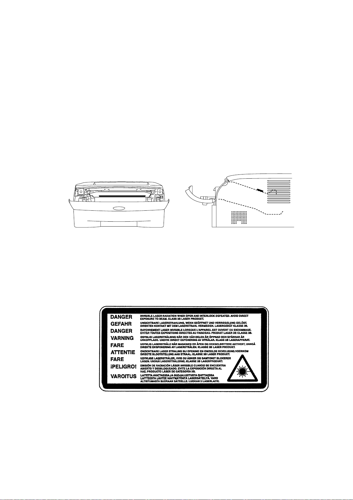
<Location of the laser beam window>
ADDITIONAL INFORMATION
When servicing the optical system of the printer, be careful not to place a screwdriver or
other reflective object in the path of the laser beam. Be sure to take off any personal
accessories such as watches and rings before working on the printer. A reflected beam,
though invisible, can permanently damage the eyes.
Since the beam is invisible, the following caution label is attached on the laser unit.
ix Confidential
Page 12
DEFINITIONS OF WARNINGS, CAUTIONS AND NOTES
The following conventions are used in this service manual:
WARNING
Indicates warnings that must be observed to prevent possible personal injury.
CAUTION:
!
Indicates cautions that must be observed to service the printer properly or prevent damage
to the printer.
NOTE:
Indicates notes and useful tips to remember when servicing the printer.
**Listed below are the various kinds of “WARNING” messages included in this manual.
WARNING
Always turn off the power switch and unplug the power cord from the power outlet
before accessing any parts inside the printer.
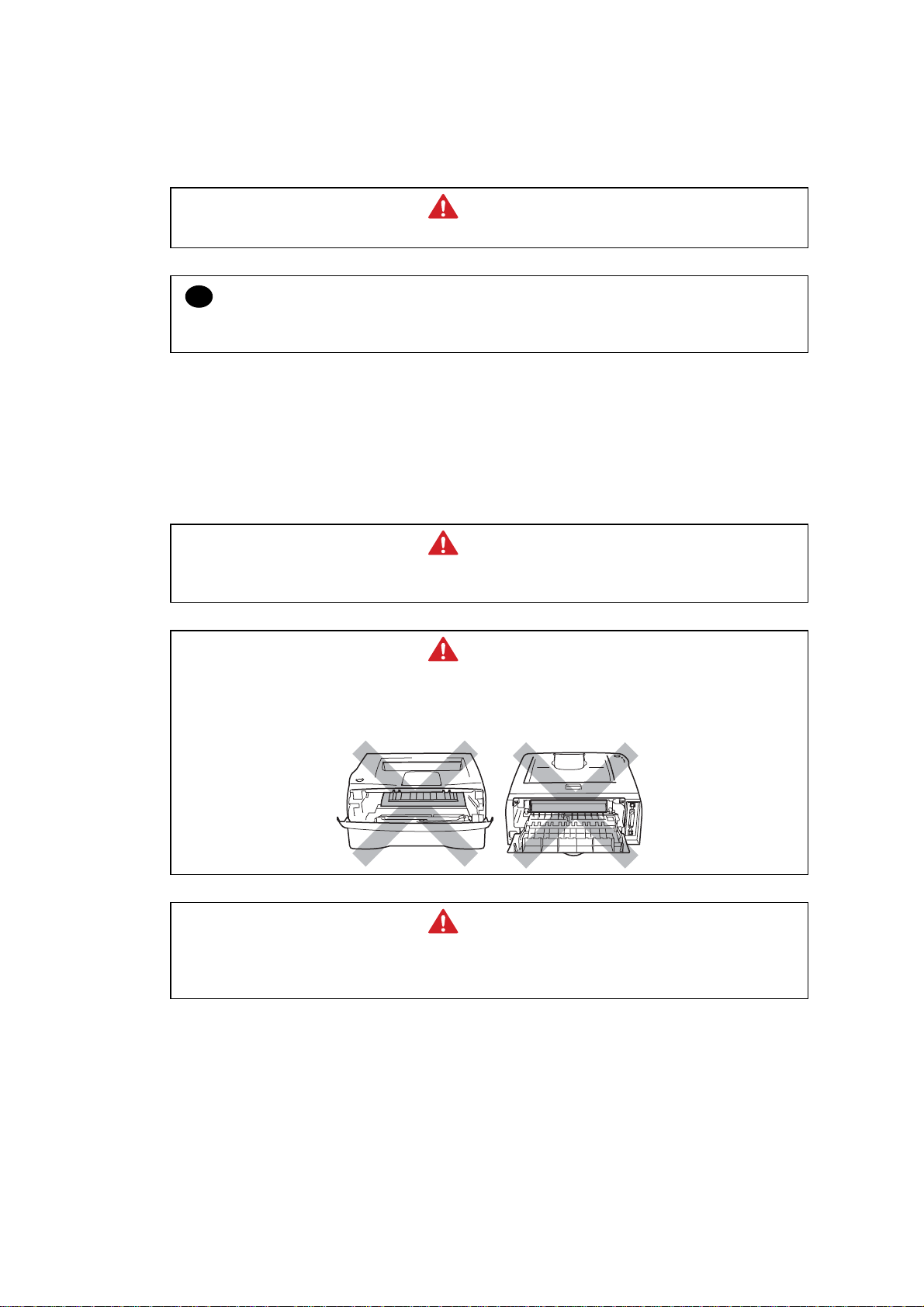
WARNING
Some parts inside the printer are extremely hot immediately after the printer is used.
When opening the front cover or back cover to access any parts inside the printer,
never touch the shaded parts shown in the following figures.
WARNING
If you analyze malfunctions with the power plug inserted into the power outlet,
special caution should be exercised even if the power switch is OFF because it is a
single pole switch.
x Confidential
Page 13

CHAPTER 1 GENERAL
1. FEATURES
This printer has the following features.
High Resolution and Fast Print Speed
True 600 x 600 dots/ true 300 x 300 dots per inch (dpi) and HQ1200 for graphics with microfine
toner and up to 16 (HL-2030)/ 20 (HL-2040/2070N) pages per minute (ppm) print speed for A4
and 17 (HL-2030)/ 20 (HL-2040/2070N) pages per minute (ppm) print speed for Letter- size
paper.
Versatile Paper Handling
The printer loads paper automatically from the paper tray. The paper tray can hold A4, letter,
B5 (ISO), B5 (JIS), A5, B6 (ISO), A6, Executive, Folio and Legal* size of paper. The manual
feed slot allows manual paper loading sheet by sheet so you can use a variety of types and
sizes of paper. *Legal paper is not available in some regions.
HL-2030/2040/2070N SERVICE MANUAL
Front Operation
Basic operation of the printer can be controlled from the control panel.
Enhanced Printing Performance and User-Friendly Operation for Windows
The dedicated printer driver for Microsoft
Windows
install them into your Windows
2000/XP are available on the CD-ROM supplied with your printer. You can easily
system using our installer program. The driver supports our
unique compression mode to enhance printing speed in Windows
Windows 95/98/Me, Windows NT 4.0 and
applications and allows you
to choose various printer settings including toner save mode, custom paper size, sleep mode,
gray scale adjustment, resolution, water mark and many layout functions. You can easily setup
these print options through the Printer Setup Menu.
Printer Status Monitor with Bi-directional Parallel Interface (For HL-2040/2070N)
The printer driver can monitor the status of your printer using bi-directional parallel
communications. IEEE-1284 bi-directional parallel printer cable is recommended.
The printer status monitor program can show the current status of your printer. When printing,
the animated dialog box appears on your computer screen to show the current printing
process. If an error occurs, a dialog box will appear to let you know what to correct. If you
have turned on the Interactive Help (Windows only) you can get visual guidance on your PC
screen on the actions in the event of certain printer errors. The default setting is OFF.
Quick Print Setup
The Quick Print Setup is a convenient utility to allow you to make changes to frequently used
driver settings easily without having to open the printer properties selection box every time. It
is launched automatically when this printer driver is selected. You can change the settings by
clicking on the icon with the right mouse button. The default setting is OFF.
Enhanced Memory Management
The printer provides its own data compression technology in its printer hardware and the
supplied printer driver software, which can automatically compress graphic data and font data
efficiently into the printer’s memory. You can avoid memory errors and print most full pages
600 dpi graphic and text data, including large fonts, with the standard printer memory.
1-1
Confidential
Page 14

CHAPTER 1 GENERAL
USB Interface (for Windows
98/Me/2000/XP, Mac OS
9.1-9.2/ Mac OS
X 10.2.4 or
greater)
The printer can be connected using the Universal Serial Bus (USB) interface to a PC or Mac
which has a USB interface. Drivers that allow you to use the USB port are provided on the CDROM supplied with the printer.
Popular Printer Emulation Support
These printers support the following printer emulation modes.
HL-2030/2040: GDI
HL-2070N: HP LaserJet (PCL6), Epson FX-850 and IBM Proprinter XL.
Environment-Friendly
<Economy Printing Mode>
This feature will cut your printing cost by saving toner. It is useful for obtaining draft copies for
proof-reading. You can select the toner saving economy mode through the Windows
printer
driver supplied with your printer.
<Sleep Mode (Power Save Mode)>
Sleep mode automatically reduces power consumption when the printer is not in use for a
certain period of time. The printer consumes less than 5W (HL-2030/2040) or 7W (HL-2070N)
when in sleep mode.
<Low Running Cost>
Since the toner cartridge is separate from the drum unit, you need to replace only the toner
cartridge after printing around 2,500 (Standard toner cartridge) pages at 5% coverage for A4
paper for the standard cartridge, which is both cost effective and ecologically friendly.
Bar Code Print (for HL-2070N only)
The printer can print the following 11 types of bar codes
• Code 39 • US-PostNet • EAN-8
• Code 128 • ISBN • EAN-13
• Interleaved 2 of 5 • UPC-A • EAN-128
• Codabar • UPC-E
Network Feature (for HL-2070N only)
The Brother printer has built in multi protocol network capability as standard. This allows
multiple host computers to share the printer on a 10/100Mbps Ethernet network. Any users
can print their jobs as if the printer was directly connected to their computer. Users on
Windows
®
95/98/Me, Windows® NT4.0, Windows® 2000/XP, Mac OS® 9.1 to 9.2, Mac OS® X
10.2.4 or greater simultaneously can access this printer. For further information, see the
Network User’s Guide supplied with the printer.
1-2
Confidential
Page 15
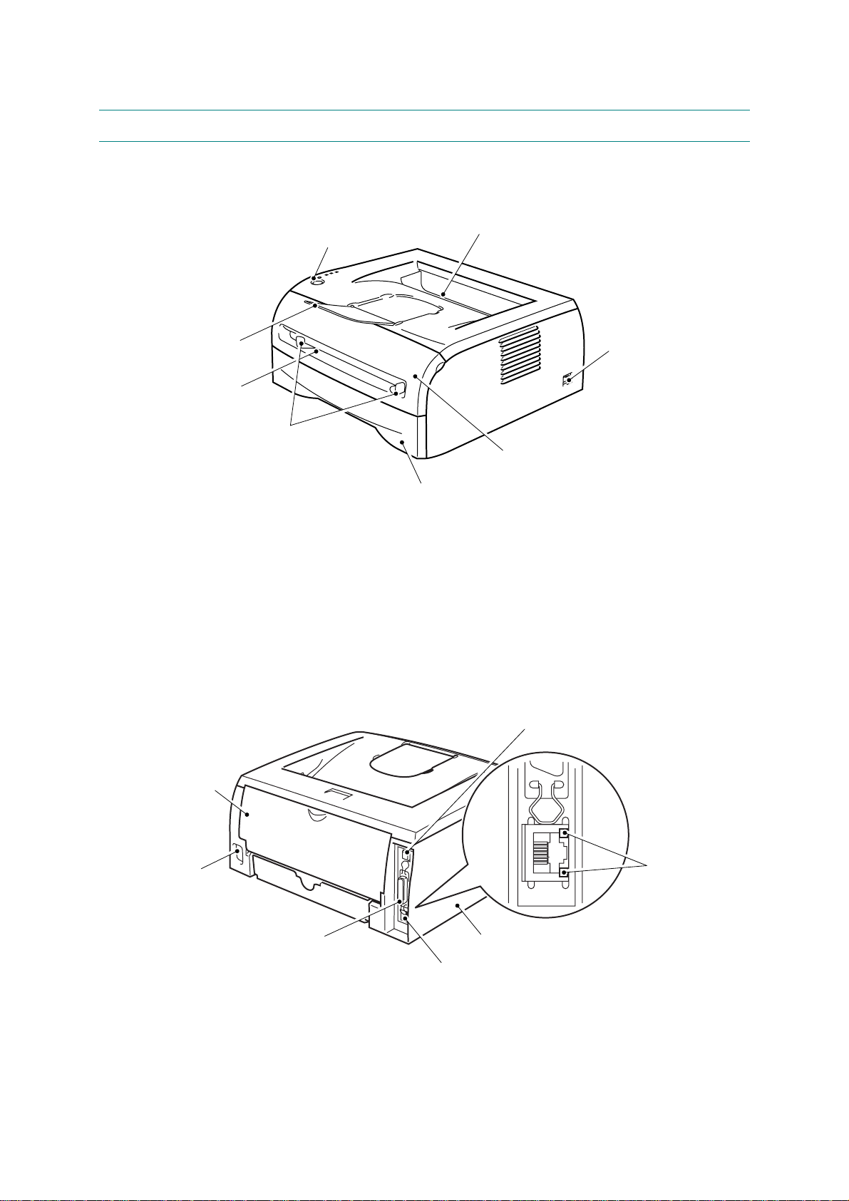
2. OVERVIEW
A
<Front View>
HL-2030/2040/2070N SERVICE MANUAL
Face-down Output Tray
Control Panel
Face-down Output Tray
Support Flap
(Support Flap)
Manual Feed Slot
<Rear View>
Manual Feed Paper Guides
*The printer illustration is based on HL-2070N.
Paper Tray
Fig. 1-1
Power Switch
Front Cover
USB Interface Connector
Back Cover
LED
(Light-emitting Diode)
(HL-2070N)
C Power
Connector
Parallel Interface Connector
(HL-2040 and HL-2070N)
Side cover
10/100Baser TX Port
(HL-2070N)
*The printer illustration is based on HL-2070N.
Fig. 1-2
1-3
Confidential
Page 16

CHAPTER 1 GENERAL
3. SPECIFICATIONS
3.1 Printing
Print method Electrophotography by semiconductor laser beam scanning
Laser Wavelength: 760 - 810nm
Output: 5mW max
Resolution
Windows® 95 and
WindowsNT
Windows®98/Me,
Windows
Windows
DOS
Mac OS
Linux
®
4.0
®
2000 and
®
XP
®
HL-2030 HL-2040 HL-2070N
N/A HQ1200/ 600dpi/ 300dpi
HQ1200/ 600dpi/ 300dpi
N/A 600dpi
HQ1200/ 600dpi/ 300dpi
600dpi/ 300dpi
Print quality Normal printing mode
Economy printing mode (Toner saving mode)
Print speed Normal
<HL-2030>
Up to 16 pages/minute (A4)
Up to 17 pages/minute (Letter-size paper)
<HL-2040/ HL-2070N>
Up to 20 pages/minute (A4)
Up to 20 pages/minute (Letter-size paper)
Warm-up Max. 18 seconds at 23°C (73.4°F)
First print Less than 10 seconds when the printer is in the ready state.
(when loading A4 or Letter-size paper from the standard paper tray)
Consumables <Toner cartridge>
Life expectancy:
Starter 1,500 pages / cartridge
Standard 2,500 pages / cartridge
* when printing A4 or Letter-size paper at 5% print coverage.
<Drum unit>
Life expectancy: 12,000 A4 or Letter pages/drum unit
NOTE:
Print speed varies depending on the paper size or media type. For details, refer to 3.8 ‘Print
Speeds with Various Settings’ in this chapter.
1-4
Confidential
Page 17

3.2 Functions
CPU HL-2030/ HL-2040: Fujitsu SPARClite 96MHz
HL-2070N: Fujitsu SPARClite 133MHz
Emulation HL-2030/2040: GDI
HL-2070N: HP LaserJet (PCL)
EPSON FX-850 or IBM Proprinter XL
Printer driver <HL-2030>
HL-2030/2040/2070N SERVICE MANUAL
GDI Driver for Windows® 98/Me, Windows® 2000 and Windows® XP
•
Brother Laser Driver for Mac OS® 9.1 to 9.2 and Mac OS® X 10.2.4 or
•
greater
GDI Printer Driver for Linux
•
<HL-2040>
•
GDI Driver for Windows® 95/98/Me, Windows NT® 4.0, Windows® 2000
and Windows® XP
Brother Laser Driver for Mac OS® 9.1 to 9.2 and Mac OS® X 10.2.4 or
•
greater
GDI Printer Driver for Linux
•
< HL-2070N >
PCL Driver for Windows® 95/98/Me, Windows NT® 4.0, Windows® 2000
•
and Windows® XP
Generic PCL Driver for Windows NT® 4.0, Windows® 2000 and
•
Windows® XP
Brother Laser Driver for Mac OS® 9.1 to 9.2 and Mac OS® X 10.2.4 or
•
greater
GDI Printer Driver for Linux
•
Interface Standard:
HL-2030 HL-2040 HL-2070N
Full-Speed USB 2.0 Full-Speed USB 2.0
IEEE 1284 Parallel
Full-Speed USB 2.0
IEEE 1284 Parallel,
10/100 BASE-TX
Option:
HL-2030 HL-2040 HL-2070N
IEEE 802.11b
wireless
(NC-2200w)
IEEE 802.11b
wireless
(NC-2200w)
10/100 BASE-TX
(NC-2100p)
IEEE 802.11b
wireless
(NC-2200w)
Utilities HL-2030/2040: Interactive Help*
HL-2070N: Interactive Help, Driver Deployment Wizard*
* Interactive Help: Instructional animations for problem solving.
* The Driver Deployment Wizard automates the installation of a printer
in a peer-to-peer network.
Memory HL-2030/2040: 8 Mbytes
HL-2070N: 16 Mbytes
Option: N/A
Control Panel • Display LED: 4 LEDs
• Button 1 button
Diagnostics Self-diagnostic program
Resident Fonts HL-2030/2040: N/A
HL-2070N: 49 scalable fonts, 12 bitmap fonts, 11 bar codes;
Code39, Interleaved 2 of 5, EAN-8, EAN-13, UPC-A, EAN-128,
Codabar, FIM (US-PostNet), ISBN, Code128
1-5
Confidential
Page 18

CHAPTER 1 GENERAL
3.3 Electronics and Mechanics
Power source U.S.A. and Canada: AC 110 to 120V, 50 Hz/60 Hz
Europe and Australia: AC 220 to 240V, 50 Hz/60 Hz
Power consumption Printing: Less than 450 W at 25°C (77°F)
(average) Standing by: Less than 70 W at 25°C (77°F)
Sleep: Less than 5 W (HL-2030/2040)
Less than 7 W (HL-2070N)
Noise <Sound pressure>
Printing: Less than 51dB (A)
Standing by: Less than 30dB (A)
<Sound power>
Printing: 6.2B(A)
(Office equipment with LWAd<6.3B(A) is not suitable for operation in
Standing by; 4.3B(A)
Temperature Operating: 10 to 32.5°C (50 to 90.5°F)
Non operating: 0 to 40°C (38 to 104°F)
Storage: -20 to 40°C (-4 to 104°F)
rooms where predominantly intellectual work is done. Due to there
noise emissions, these devices should be separate rooms.)
Humidity Operating: 20 to 80% (non condensing)
Storage: 10 to 85% (non condensing)
Dimensions 371 x 361 x 165.5 mm
(W x D x H) (14.6 x 14.2 x 6.5 inches)
Weight Approximately 5.4 kg (12.0lb) not including the drum unit and toner
cartridge.
Approximately 6.5 kg (14.3lb) including the drum unit and toner
cartridge
NOTE:
The power consumption figure quoted for sleep mode is when the fan has stopped.
1-6
Confidential
Page 19

3.4 Service Information
These are key service information to maintain the product.
Machine Life: 50,000 pages/ 5 years
MTBF (Meantime between failure): Up to 4,000 hours
MTTR (Meantime to repair): Average 30 minutes
Monthly volume: 10,000 pages
Periodical replacement parts:
There is no periodical replacement part that needs to be replaced periodically to maintain the
product quality.
HL-2030/2040/2070N SERVICE MANUAL
1-7
Confidential
Page 20

CHAPTER 1 GENERAL
3.5 Network Connectivity
<Standard>
Type/Speed 10/100 Base TX Ethernet
Automatic negotiation
Protocols TCP/IP (APR, RARP, BOOTP, DHCP, APIPA (Auto IP), NetBIOS
Management Tool • Web Based Management (HTTPD)
• BRAdmin Professional
• Web BRAdmin
Supplied software • BRAdmin Professional utility (for Windows
• Web BRAdmin (Windows
W eb BRAdmin is NOT supplied with CD-ROM. Available only on
Name Resolutions, WINS, DNS Resolver, LPR/LPD, Custom Raw
Port/Port9100, SMTP Client, SMB Print, IPP, FTP Server, mDNS,
TELNET, SNMP, HTTP)
4.0/Windows
2000/XP)
Server, Windows
XP Professional)
2000 Professional/ Server/ Advanced
95/98/ME, WindowsNT
Web page. For more information on W eb BRAdmin Professional,
refer to http://solutions.brother.com
1-8
Confidential
Page 21
3.6 Paper
3.6.1 Feedable paper
(1) Paper type
HL-2030/2040/2070N SERVICE MANUAL
Paper type
Plain paper
60 g/m2 to 105 g/m
(16 to 28 lbs.)
Recycled paper
Bond paper
Thick paper
105 g/m2 to 161 g/m
(28 to 43 lbs.)
Transparency
Label
Envelop
Card Stock
2
Tray1
Manual feed
slot
Select the paper type from
the printer driver
O O Plain paper
O O Recycled paper
O
2
X
O
Up to 10 sheets
A4 or Letter
X
X O
O Bond paper
O Thick paper or Thicker paper
O
A4 or Letter
O
A4 or Letter
Transparency
Thicker paper
Envelope
or Env.Thick or Env.Thin
X O Thick paper or Thicker paper
(2) Paper size
Paper Tray Manual feed slot
Paper size
A4, Letter, Legal*, B5 (ISO),
Executive, A5, A6, B6 (ISO),
B5 (JIS), Folio*
Width:
69.9 to 215.9 mm
(2.75 to 8.5 in.)
Length:
116 to 406.4 mm
(4.57 to 16.0 in.)
* Legal and Folio are not available in some regions.
1-9
Confidential
Page 22
CHAPTER 1 GENERAL
(3) Other paper specifications
<Paper tray>
Basis weight
Caliper
Moisture content
2
60 to 105 g/m
(16 to 28 lb.)
0.08 to 0.12 mm (0.003 to 0.005 in.)
4% to 6% by weight
Cut sheet
<Manual feed slot>
Basis weight
Caliper
Moisture content
2
60 to 161 g/m
(16 to 43 lb.)
0.08 to 0.19 mm (0.003 to 0.007 in.)
4% to 6% by weight
Cut sheet
(4) Recommended paper
Europe USA
Plain paper
Xerox Premier 80 g/m
Xerox Business 80 g/m
2
2
Modo Paper DATACOPY 80 g/m
Xerox 4200DP 20lb
Xerox 4024 28lb
2
Hammermill Laser Paper 24lb
IGEPA X-press 80 g/m2
Recycled paper
Transparency
Label
Xerox Recycled Supreme N/A
3M CG3300 3M CG 3300
Avery laser label L7163 Avery laser label #5160
* This printer can use recycled paper that meets the DIN 19309 specification
CAUTION:
!
When you are choosing print media, be sure to follow the information given below to prevent
any paper jams, print quality problems or printer damage;
• It is recommended to use long-grained paper for the best print quality. If short-grained
paper is being used, it might be the cause of paper jams.
• Use neutral paper. Do not use acid paper to avoid any damage to the drum unit.
• Avoid using coated paper such as vinyl coated paper.
• Avoid using preprinted or highly textured paper.
• It is recommended to use labels or transparencies which are designed for use in laser
printers.
• Avoid feeding labels with the carrier sheet exposed, or the printer will be damaged.
• Before loading paper with holes such as organizer sheets, be sure to fan the stack well.
• Do not use organizer sheets that are stuck together. The glue that is used might caused
damaged to the printer.
• When printing on the back of pre-printed paper, if the paper is curled, be sure to straighten
the paper as much as possible.
Different types of paper should not be loaded at the same time in the paper tray to avoid any
paper jams or misfeeds.
1-10
Confidential
Page 23

3.6.2 Paper tray capacity
HL-2030/2040/2070N SERVICE MANUAL
Paper Tray
Paper Capacity
3.6.3 Print delivery
Face down output tray
capacity: Maximum 100 sheets (80 g/m
Note:
Face-down:Delivery with the printed face of the paper downwards.
250 sheets (80 g/m
2
face down only
Manual feed slot
or 21lb) Single sheet
2
)
1-11
Confidential
Page 24
CHAPTER 1 GENERAL
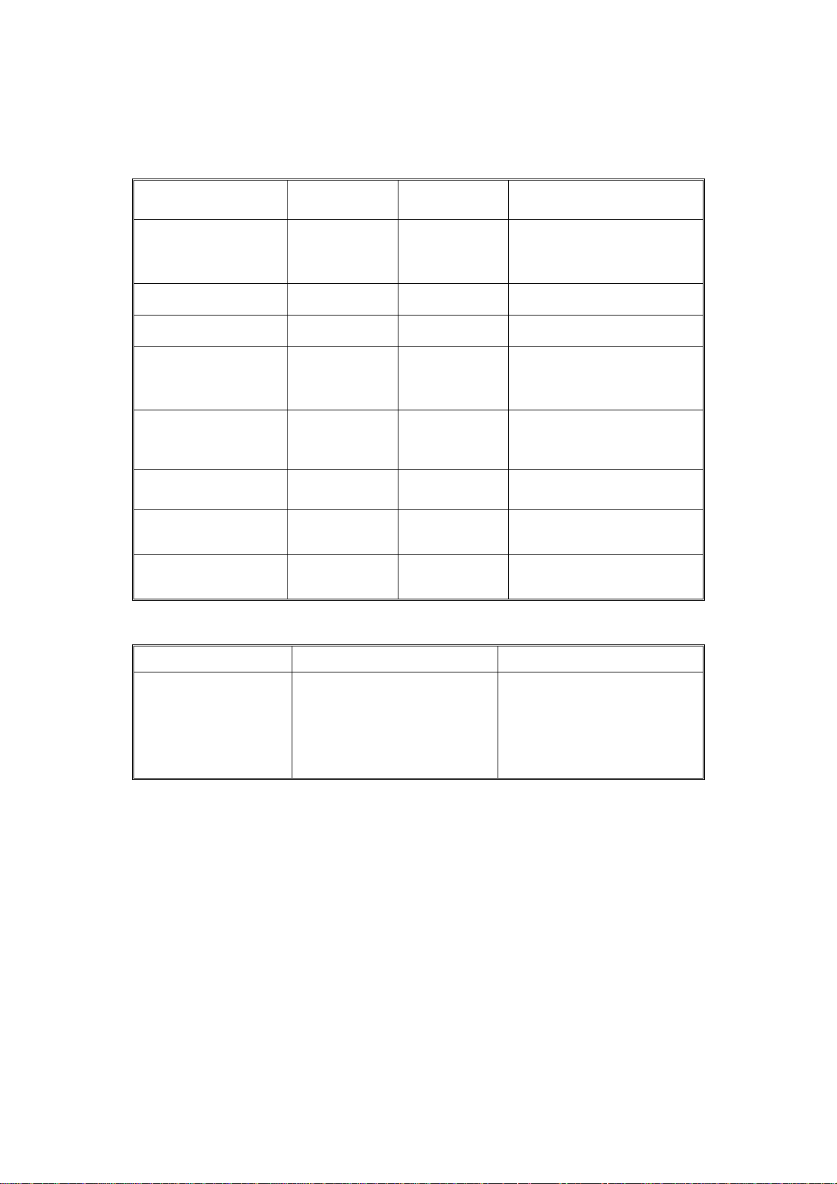
3.7 Printable Area
3.7.1 PCL5e/EPSON/IBM emulation
When using PCL emulation, the edges of the paper that cannot be printed on are shown
below.
Portrait
E
G
NOTE:
G
G
C
A
F
Physical page
Printable area
Logical page
E
B
D
G
F
B Physical page length
D
F
Maximum logical page length
Distance from edge of physical page to
edge of logical page
• “Logical page” shows the printable area for a PCL driver.
• “Printable area” shows mechanical printable area of the machine.
• Therefore, the machine can only print within the shaded area when you use a PCL driver.
1-12
Confidential
Page 25

HL-2030/2040/2070N SERVICE MANUAL
The table below shows the printable areas when printing on Portrait for each paper size.
Size A B C D E F G
Letter
Legal
Folio
Executive
A 4
A 5
A 6
B 5 (JIS)
B 5 (ISO)
B 6 (ISO)
COM10
MONARCH
C 5
DL
DL L
215.9 mm
8.5”
(2,550 dots)
215.9 mm
8.5”
(2,550 dots)
215.9 mm
8.5”
(2,550 dots)
184.15 mm
7.25”
(2,175 dots)
210.0 mm
8.27”
(2,480 dots)
148.5 mm
5.85”
(1,754 dots)
105.0 mm
4.13”
(1,240 dots)
182.0 mm
7.1”
(2,130 dots)
176.0 mm
6.93”
(2,078 dots)
125.0 mm
4.92”
(1,476 dots)
104.78 mm
4.125”
(1,237 dots)
98.43 mm
3.875”
(1,162 dots)
162.0 mm
6.38”
(1,913 dots)
110.0 mm
4.33”
(1,299 dots)
220.0 mm
8.66”
(2,598 dots)
279.4 mm
11.0”
(3,300 dots)
355.6 mm
14.0”
(4,200 dots)
330.2mm
13.0”
(3,900 dots)
266.7 mm
10.5”
(3,150 dots)
297.0 mm
11.69”
(3,507 dots)
210.0 mm
8.27”
(2,480 dots)
148.5 mm
5.85”
(1,754 dots)
257.0 mm
10.11”
(3,033 dots)
250.0 mm
9.84”
(2,952 dots)
176.0 mm
6.93”
(2,078 dots)
241.3 mm
9.5”
(2,850 dots)
190.5 mm
7.5”
(2,250 dots)
229.0 mm
9.01”
(2,704 dots)
220.0 mm
8.66”
(2,598 dots)
110.0 mm
4.33”
(1.299 dots)
203.2 mm
8.0”
(2,400 dots)
203.2 mm
8.0”
(2,400 dots)
203.2 mm
8.0”
(2,400 dots)
175.7 mm
6.92”
(2,025 dots)
198.0 mm
7.79”
(2,338 dots)
136.5 mm
5.37”
(1,612 dots)
93.0 mm
3.66”
(1,098 dots)
170.0 mm
6.69”
(2,007 dots)
164.0 mm
6.46”
(1,936 dots)
164.0 mm
4.44”
(1,334 dots)
92.11 mm
3.63”
(1,087 dots)
85.7 mm
3.37”
(1,012 dots)
150.0 mm
5.9”
(1,771 dots)
98.0 mm
3.86”
(1,157 dots)
207.4 mm
8.17”
(2,450 dots)
279.4 mm
11.0”
(3,300 dots)
355.6 mm
14.0”
(4,200 dots)
330.2mm
13.0”
(3,900 dots)
266.7 mm
10.5”
(3,150 dots)
297.0 mm
11.69”
(3,507 dots)
210.0 mm
8.27”
(2,480 dots)
148.5 mm
5.85”
(1,754 dots)
257.0 mm
10.11”
(3,033 dots)
250.0 mm
9.84”
(2,952 dots)
176.0 mm
6.93”
(2.078 dots)
241.3 mm
9.5”
(2,850 dots)
190.5 mm
7.5”
(2,250 dots)
229.0 mm
9.01”
(2,704 dots)
220.0 mm
8.66”
(2,598 dots)
110.0 mm
4.33”
(1.299 dots)
6.35 mm
0.25”
(75 dots)
Ç
Ç
6.35 mm
0.25”
(75 dots)
6.01 mm
0.24”
(71 dots)
Ç
Ç
Ç
Ç
Ç
6.35 mm
0.25”
(75 dots)
Ç
6.01 mm
0.24”
(71 dots)
Ç
6.27 mm
0.25”
(74 dots)
0 mm
0 mm
0 mm
0 mm
0 mm
0 mm
0 mm
0 mm
0 mm
0 mm
0 mm
0 mm
0 mm
0 mm
0 mm
4.2 mm
0.16”
(50 dots)
4.2 mm
0.16”
(50 dots)
4.2 mm
0.16”
(50 dots)
4.2 mm
0.16”
(50 dots)
4.2 mm
0.16”
(50 dots)
4.2 mm
0.16”
(50 dots)
4.2 mm
0.16”
(50 dots)
4.2 mm
0.16”
(50 dots)
4.2 mm
0.16”
(50 dots)
4.2 mm
0.16”
(50 dots)
4.2 mm
0.16”
(50 dots)
4.2 mm
0.16”
(50 dots)
4.2 mm
0.16”
(50 dots)
4.2 mm
0.16”
(50 dots)
6.27 mm
0.25”
(74 dots)
NOTE:
• The paper sizes indicated here should confirm to the nominal dimensions specified by JIS
except B5 (ISO), B6 (ISO).
• The dot size is based on 300 dpi resolution.
1-13
Confidential
Page 26
CHAPTER 1 GENERAL
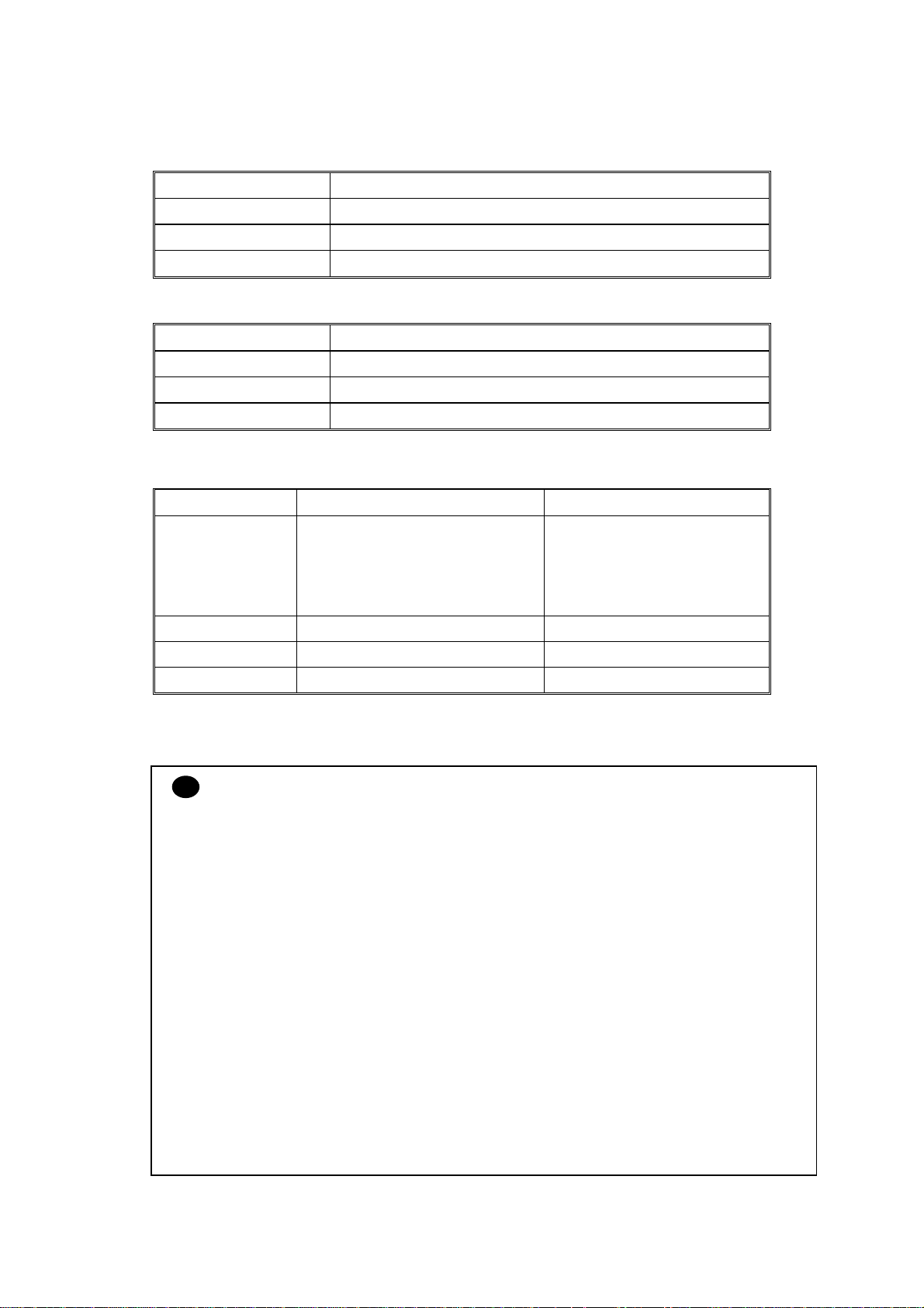
Landscape
E
G
NOTE:
G
G
F
Physical page
Printable area
E
D
B
G
B Physical page length
D Maximum logical page length
F Distance from edge of physical
page to edge of logical page
F
Logical page
C
A
• “Logical page” shows the printable area for a PCL driver.
• “Printable area” shows mechanical printable area of the machine.
• Therefore, the machine can only print within the shaded area when you use a PCL driver.
1-14
Confidential
Page 27

HL-2030/2040/2070N SERVICE MANUAL
The table below shows the printable areas when printing on Landscape for each paper size.
Size A B C D E F G
Letter
Legal
Folio
Executive
A 4
A 5
A 6
B 5 (JIS)
B 5 (ISO)
B 6 (ISO)
COM10
MONARCH
C 5
DL
DL L
279.4 mm
11.0”
(3,300 dots)
355.6 mm
14.0”
(4,200 dots)
330.2mm
13.0”
(3,900 dots)
266.7 mm
10.5”
(3,150 dots)
297.0 mm
11.69”
(3,507 dots)
210.0 mm
8.27”
(2,480 dots)
148.5 mm
5.85”
(1,754 dots)
257.0 mm
10.11”
(3,033 dots)
250.0 mm
9.84”
(2,952 dots)
176.0 mm
6.93”
(2,078 dots)
241.3 mm
9.5”
(2,850 dots)
190.5 mm
7.5”
(2,250 dots)
229 mm
9.01”
(2,704 dots)
220 mm
8.66”
(2,598 dots)
110 mm
4.33”
(1,299 dots)
215.9 mm
8.5”
(2,550 dots)
215.9 mm
8.5”
(2,550 dots)
215.9 mm
8.5”
(2,550 dots)
184.15 mm
7.25”
(2,175 dots)
210.0 mm
8.27”
(2,480 dots)
148.5 mm
5.85”
(1,754 dots)
105.0 mm
4.13”
(1,240 dots)
182.0 mm
7.1”
(2,130 dots)
176.0 mm
6.93”
(2,078 dots)
125.0 mm
4.92”
(1,476 dots)
104.78 mm
4.125”
(1,237 dots)
98.43 mm
3.875”
(1,162 dots)
162 mm
6.38”
(1,913 dots)
110 mm
4.33”
(1,299 dots)
220 mm
8.66”
(2,598 dots)
269.3 mm
10.6”
(3,180 dots)
345.5 mm
13.6”
(4,080 dots)
320.0mm
12.6”
(3,780 dots)
256.6 mm
10.1”
(3,030 dots)
287.0 mm
11.2”
(3,389 dots)
200.0mm
7.87”
(2,362 dots)
138.5 mm
5.45”
(1,636 dots)
247.0 mm
9.72”
(2,916 dots)
240.0 mm
9.44”
(2,834 dots)
166.4 mm
6.55”
(1,960 dots)
231.1 mm
9.1”
(2,730 dots)
180.4 mm
7.1”
(2,130 dots)
219.0 mm
8.62”
(2,586 dots)
210.0 mm
8.26”
(2,480 dots)
97.5 mm
3.84”
(1,151 dots)
215.9 mm
8.5”
(2,550 dots)
215.9 mm
8.5”
(2,550 dots)
215.9 mm
8.5”
(2,550 dots)
184.15 mm
7.25”
(2,175 dots)
210.0 mm
8.27”
(2,480 dots)
148.5 mm
5.85”
(1,754 dots)
105.0 mm
4.13”
(1,240 dots)
182.0 mm
7.1”
(2,130 dots)
176.0 mm
6.93”
(2,078 dots)
125.0 mm
4.92”
(1,476 dots)
104.78 mm
4.125”
(1,237 dots)
98.43 mm
3.875”
(1,162 dots)
162 mm
6.38”
(1,913 dots)
110 mm
4.33”
(1,299 dots)
220 mm
8.66”
(2,598 dots)
5.0 mm
0.2”
(60 dots)
Ç
Ç
5.0 mm
0.2”
(60 dots)
4.8 mm
0.19”
(59 dots)
Ç
Ç
Ç
Ç
Ç
5.0 mm
0.2”
(60 dots)
Ç
4.8 mm
0.19”
(59 dots)
Ç
6.27 mm
0.25”
(74 dots)
0 mm
0 mm
0 mm
0 mm
0 mm
0 mm
0 mm
0 mm
0 mm
0 mm
0 mm
0 mm
0 mm
0 mm
0 mm
4.2 mm
0.16”
(50 dots)
4.2 mm
0.16”
(50 dots)
4.2 mm
0.16”
(50 dots)
4.2 mm
0.16”
(50 dots)
4.2 mm
0.16”
(50 dots)
4.2 mm
0.16”
(50 dots)
4.2 mm
0.16”
(50 dots)
4.2 mm
0.16”
(50 dots)
4.2 mm
0.16”
(50 dots)
4.2 mm
0.16”
(50 dots)
4.2 mm
0.16”
(50 dots)
4.2 mm
0.16”
(50 dots)
4.2 mm
0.16”
(50 dots)
4.2 mm
0.16”
(50 dots)
6.27 mm
0.25”
(74 dots)
NOTE:
• The paper sizes indicated here should confirm to the nominal dimensions specified by JIS
except B5 (ISO), B6 (ISO).
• The dot size is based on 300 dpi resolution.
3.7.2 PCL6 emulation
You can not print within 4.2 mm (50dots in 300 dpi mode) on all four sides of the paper.
1-15
Confidential
Page 28

CHAPTER 1 GENERAL
3.8 Print Speeds with Various Settings
Print speed is up to 16 ppm for A4 size, 17 ppm for Letter size (HL-2030) and 20 ppm (HL2040/2070N) when loading A4 or Letter size paper from the paper tray in the plain paper mode.
Actual print speed varies depending on the media type or paper size as shown in the tables
below;
<A4 / Letter size>
Media type setting All models
Transparency Up to 16/17 ppm (HL-2030)
Up to 20 ppm (HL-2040/2070N)
Thin Paper Up to 16/17 ppm (HL-2030)
Up to 20 ppm (HL-2040/2070N)
Plain Paper,
Recycled Paper
Thick Paper,
Envelopes, Env.Thin
Thicker/Bond Paper,
Up to 16/17 ppm (HL-2030)
Up to 20 ppm (HL-2040/2070N)
10 ppm (HL-2030)
10 ppm (HL-2040/2070N)
4 ppm *
Env.Thick
<Smaller size than A4 or Letter>
Media type setting All models
Transparency Up to 16/17 ppm (HL-2030)
Up to 20 ppm (HL-2040/2070N)
Thin Paper Up to 16/17 ppm (HL-2030)
Up to 20 ppm (HL-2040/2070N)
Plain Paper,
Recycled Paper
300sec. 16/17 ppm Æ 8 ppm (HL-2030)
300sec. 20 ppm Æ 8 ppm (HL-2040/2070N)
Env.Thin 300sec. 10 ppm Æ 8 ppm (HL-2030)
300sec. 10 ppm Æ 8 ppm (HL-2040/2070N)
Thick Paper,
Envelopes
30sec. 10 ppm Æ 8 ppm (HL-2030)
30sec. 10 ppm Æ 8 ppm (HL-2040/2070N)
Thicker/Bond Paper,
4 ppm *
Env.Thick
NOTE:
• The print speed may vary according to conditions, such as paper size and paper tray.
• When a smaller size paper than A4 or Letter is printed, the temperature on both edges of
the fixing unit is much higher than the temperature on the center of the unit where the paper
is fed depending on the setting or model. Therefore, the print speed is slowed in order to
decrease the temperature on the edges after the specified time, it is maximum print speed
when you first start printing.
• The actual print speed varies depending on the paper size.
1-16
Confidential
Page 29

HL-2030/2040/2070N SERVICE MANUAL
3.9 Toner Cartridge Weight Information
Toner Cartridge Weight (approximate weight)
Brand new Toner Cartridge Weight 630g 570g
Toner Weight at Brand New Toner Cartridge 100g 100g
Toner Cartridge Weight at Toner Near Empty 576g 516g
Remain Toner Weight at Toner Near Empty 46g 46g
Toner Cartridge Weight at Toner Life End 574g 516g
Remain Toner Weight at Toner Life End 44g 44g
TN2000 only
TN350 / TN2050 /
TN2025
You can print 500 pages (± 100 pages) with 10g toner. (5% coverage)
NOTE:
• Without yellow protector
• Toner cartridge weight may vary within 2 to 3g depending on the cartridge weight.
• The weight of the starter toner cartridge is as follows,
For TN2000 model, the starter toner cartridge weight is 610g, and the toner weight is 80g.
For TN350, TN2050 and TN2025 models, the starter toner cartridge weight is 550g, and
the toner weight is 80g.
• The weight difference between TN2000 and other models is the weight difference of the
developing roller. The weight of TN2000 will be the same with TN350 from summer in
2005.
1-17
Confidential
Page 30

CHAPTER 1 GENERAL
4. SERIAL NO. DESCRIPTIONS
The descriptions below show how to understand the meanings of the numbers printed on the
labels or bag of the printer and printer parts.
< ID for production month >
A: January B: February C: March D: April
E: May F: June G: July H: August
J: September K: October L: November M: December
< ID for year >
4: 2004 5: 2005
< ID for factory >
9: Kariya Plant A: Mie Brother C: BIUK
J: Buji Nan Ling Factory
(1) Printer: Printed on the label attached on the rear of the main body
<Example>
(2) Process unit: Imprinted on the aluminum bag
<MODEL NO.>
< SERIAL NO. >
U 5 2 6 8 2 A 3 J 1 1 1 1 0 1
SEQUENTIAL NO.
FACTORY ID NO.
YEAR
MONTH
(Drum unit with toner cartridge)
3 A 1 1 J A
(3) Drum unit: Printed on the bar code label attached inside the drum unit
YEAR
MONTH
PRODUCTION LINE NO.
FACTORY ID NO.
DATE
A 3 J 5 1 0 0 1 0 4 A
MONTH
YEAR
FACTORY ID NO.
TONER VOLUME
SERIAL NO.
PRODUCTION LINE NO.
DR/TN REUSE
The first time: M
The second time: N
The third time: P
1-18
Confidential
Page 31

HL-2030/2040/2070N SERVICE MANUAL
A
(4) Toner cartridge: Imprinted on the aluminum bag
3 A 3 0 J A
YEAR
MONTH
PRODUCTION LINE NO.
FACTORY ID NO.
DATE
Printed on the bar code label attached on the toner cartridge
CARTRIDGE
PRODUCTION INFO.
M 3 J L 0 0 0 1 9 9 A
MONTH
YEAR
FACTORY ID NO.
SERIAL NO.
TONER VOLUME
L: 80g
M: 100g
PRODUCTION LINE NO.
DR/TN REUSE
The first time: M
The second time: N
The third time: P
(5) Laser unit: On the laser unit
SCA T1 2 1 0000240 51 50
LSU MODEL DISTINCTION
FRAME MANUFACTURE AND MOLD
DISTINCTION
T1: THE 1st MOLD
Y3: THE 3rd MOLD
POLYGON MOTOR DISTINCTION
1: SHINANO KENSHI CO., LTD
2: MATSUSHITA ELECTRIC INDUSTRIAL CO.
3: JVC
4: SAMSUNG
DJUSTED VALUE
SERIAL NUMBER OF INSPECTION MACHINE
INSPECTION MACHINE
1-19
Confidential
Page 32

HL-2030/2040/2070N SERVICE MANUAL
CHAPTER 2 INSTALLATION AND BASIC OPERATION
1. CONDITIONS REQUIRED FOR INSTALLATION
1.1 Power Supply
• The source voltage must stay within ±10% of the rated voltage shown on the rating plate.
• The power cord, including extensions, should not exceed 5 meters (16.5 feet).
• Do not share the same power circuit with other high-power appliances, particularly an air
conditioner, copier or shredder. If it is unavoidable that you must use the printer with these
appliances, it is recommended that you use an isolation transformer or a high-frequency
noise filter.
• Use a voltage regulator if the power source is not stable.
1.2 Environment
• Setup the printer near a power outlet, so that it can be easily unplugged from the power
outlet if there is an emergency.
• The room temperature is maintained between 10°C and 32.5°C. The relative humidity is
maintained between 20% and 80%.
• The printer should be used in a well-ventilated room.
• Place the printer on a flat, horizontal surface.
• Keep the printer clean. Do not place the printer in a dusty place.
• Do not place the printer where the ventilation hole of the printer is blocked. Keep
approximately 100 mm (4 inches) between the ventilation hole and the wall.
• Do not place the printer where it is exposed to direct sunlight. Use a blind or a heavy
curtain to protect the printer from direct sunlight when the printer is unavoidably set up near
a window.
• Do not place the printer near devices that contain magnets or generate magnetic fields.
• Do not subject the printer to strong physical shocks or vibrations.
• Do not expose the printer to open flames or salty or corrosive gasses.
• Do not place objects on top of the printer.
• Do not place the printer near an air conditioner.
• Keep the printer horizontal when carrying.
• Do not cover the slots in the side cover.
2-1
Confidential
Page 33

CHAPTER 2 INSTALLATION AND BASIC OPERATION
1.3 System Requirements for Brother Printer Solution
Check the following system requirements to setup and operate the printer using Brother
Printing Solution:
Computing System
Operating System Version
95, 98, 98SE 486/ 66MHz 8MB 16MB 40MB
NT
Workstation
Windows
4.0
2000
Professional
Me Pentium 150MHz 32MB 64MB 50MB
XP Pentium 300MHz 128MB 128MB 50MB
9.1 to 9.2
OS
Apple
OS
X 10.2.4
or greater
Processor Speed
Pentium 75MHz 16MB 32MB 50MB
Pentium 133MHz 64MB 128MD 50MB
All base models
meet minimum
system
requirements
Minimum
RAM
32MB
128MB
Recommended
RAM
64MB
160MB
Available
Hard Disk
Space
50MB
2-2
Confidential
Page 34

2. UNPACKING
A
When unpacking the printer, check to see that all of the following components are included in
the carton.
HL-2030/2040/2070N SERVICE MANUAL
Printer
Drum Unit Assembly
(including Toner Cartridge)
C power cord
CD-ROM
Fig. 2-1
Quick Setup Guide
NOTE:
Components may vary depending on the country.
Interface cable
An interface cable is not a standard accessory. Please purchase the appropriate cable for the
interface you are going to use (Parallel, USB or Network).
■ Parallel cable (For HL-2040 and HL-2070N)
Most parallel cables support bi-directional communication, but some might have an
incompatible pin assignment or may not be IEEE 1284-compliant. (The Parallel cable is not
available for HL-2030.) Do not use a Parallel interface cable that is longer than 6 feet (2
meters).
■ USB cable (For Windows
98/Me/2000/XP, Mac OS 9.1–9.2/ Mac OS X 10.2.4 or greater
users only)
Please make sure that you use a Hi-Speed USB 2.0 certified cable if your computer uses a HiSpeed USB 2.0 interface.
Do not connect the USB cable to a non-powered hub or a Mac
keyboard. Please make sure
that you connect a USB cable to the USB connector of your PC when you use it.
It is recommended to use a USB interface cable that is no longer than 2 meters (6 feet).
■ Network cable (For HL-2070N)
Please use a straight-through Category5 (or greater) twist-pair cable for 10BASE-T or
100BASE-TX Fast Ethernet Network.
2-3
Confidential
Page 35

CHAPTER 2 INSTALLATION AND BASIC OPERATION
3. INSTALL THE PRINTER
Install the Printer
You need to implement hardware setup and driver installation to use the printer.
Firstly, identify the Operating System on your computer. (Windows
4.0, Windows® 2000/XP and Macintosh) Then, purchase the appropriate interface cable
(Parallel, USB or Network) for your computer. Most existing parallel cables support bidirectional communication, but some might have an incompatible pin assignment or may not
be IEEE 1284-compliant.
The installation programs for the hardware setup and driver installation are contained on the
supplied CD-ROM.
3.1 For All Users
For Windows
(1) Turn on the PC power. Insert the supplied CD-ROM into the CD-ROM drive. The
opening screen will appear automatically. Select the printer model and the language.
(2) Click the Initial Setup icon on the menu screen.
(3) You can view the Initial Setup instructions.
For Mac OS
users
10.2.4 or greater users
®
95/98/Me, Windows NT
®
(1) Turn on the PC. Insert the CD-ROM into the CD-ROM drive.
(2) Double-click the HL2000 icon on your Desktop. Double-click the Start Here OS X icon.
Follow the on-screen instructions.
(3) Click the Initial Setup icon on the menu screen.
(4) You can view the Initial Setup instructions.
For Mac OS
9.1 to 9.2 users
Go to the next page and follow the instructions.
2-4
Confidential
Page 36

3.1.1 Install the drum unit assembly
(1) Open the front cover of the printer.
(2) Unpack the drum unit assembly.
(3) Rock it from side to side several times to distribute the toner evenly inside the assembly.
(4) Put the drum unit assembly in the printer.
(5) Close the front cover of the printer.
3.1.2 Load paper in the paper tray
HL-2030/2040/2070N SERVICE MANUAL
Fig. 2-2
(1) Pull the paper tray completely out of the printer.
(2) While pressing the paper guide release lever, slide the adjusters to fit the paper size.
Check that the guides are firmly in the slots.
Paper guide release lever
Fig. 2-3
NOTE:
For Legal size paper, pull out the back of the paper tray while holding the inside latch of the
tray. (Legal size paper is not available in some regions.)
2-5
Confidential
Page 37

CHAPTER 2 INSTALLATION AND BASIC OPERATION
(3) Fan the stack of paper well to avoid paper jams and misfeeds.
(4) Put paper in the paper tray. Check that the paper is flat in the tray and below the
maximum paper mark.
NOTE:
• Paper jams may occur if you put more than 250 sheets (80g/m² or 21 lb) of plain paper in
the paper tray at one time.
• Paper jams may occur if you put more than 10 transparency in the paper tray at one time.
• When you use pre-printed paper, put the side that is going to be printed on (blank side) face
down, with the top of the paper at the front of the tray.
(5) Put the paper tray firmly back in the printer. Check that it is completely in the printer.
3.1.3 Print a test page
Fig. 2-4
(1) Turn off the printer.
(2) Make sure that the front cover is closed and the AC power cord is plugged in.
(3) All LEDs light up, and keep the Go button pressed down until the Ready LED goes off.
Release the Go button. Make sure that the Toner, Drum and Paper LEDs are off.
(4) Press the Go button again. The printer will print a test page.
Fig. 2-5
2-6
Confidential
Page 38

HL-2030/2040/2070N SERVICE MANUAL
!
Follow the instructions for your operating system and interface cable type.
3.2 For Windows® Users
For USB interface cable users
CAUTION:
If the “Found New Hardware Wizard” appears on the PC, click the Cancel button.
(1) Make sure the USB interface cable is NOT connected to the printer, and then begin
installing the driver. If you have already connected to the cable, remove it.
(2) Click “Install Printer Driver” on the Menu screen.
(3) Select the USB Cable. Read the license agreement carefully. Follow the on-screen
instructions.
(4) When this screen appears, make sure the printer power switch is on. Connect the USB
interface cable to your PC, and then connect it to the printer. Click the Next button.
Fig. 2-6
(6) Click the Finish button.
For Windows
For Windows
®
98/Me users: The setup is now complete.
®
2000/XP users: Follow the instructions below for setting the PC as the
default printer.
®
For Windows
2000/XP users only (Setting your printer as the default printer.)
(1) Click Start, and then Printers and Faxes.
Fig. 2-7
(2) Select the icon of the appropriate printer.
(3) From the File menu, select Set as Default printer.
®
For Windows
2000/XP users: The setup is now complete.
2-7
Confidential
Page 39

CHAPTER 2 INSTALLATION AND BASIC OPERATION
For Parallel Interface Cable users (HL-2040/2070N users)
(1) Click Install Printer Driver on the menu screen.
(2) Select the Parallel interface.
(3) Turn off the printer power switch.
(4) Connect the parallel interface cable to your PC, and then connect it to the printer. Read
the license agreement carefully. Then, follow the on-screen instructions.
(5) Click the Finish button. Turn on the printer power switch. The setup is now complete.
For Network Interface Cable users (for HL-2070N only)
• For connecting the printer to a network, it is recommended to contact the system
administrator prior to installation.
• For the administrator: Configure the printer referring to the following instructions.
1. For the administrator
Install the BRAdmin Professional Configuration Utility (Windows® Users Only)
The BRAdmin Professional software is designed to manage your Brother network connected
devices. For more information on BRAdmin Professional, go to http://solutions.brother.com
(1) Insert the CD-ROM into your CD-ROM drive. The opening screen will appear
automatically. Follow the on-screen instructions.
(2) Click the Install Other Drivers or Utilities icon on the menu screen.
(3) Click BRAdmin Professional. Follow the instructions on the screen.
NOTE:
• The default password for the print server is “access”. You can use the BRAdmin
Professional software or a web browser to change this password.
• Please use the BRAdmin Professional utility version that was supplied on the CD-ROM
with your Brother product. You can also download the latest Brother BRAdmin
Professional utility version from http://solutions.brother.com
Windows
®
users.
. This utility is only available for
• If you are using Personal Firewall software, disable it. Once you are sure that you can
print, re-start your Personal Firewall software.
Setting your IP Address, Subnet Mask and Gateway using BRAdmin Professional
(Windows
®
Users Only)
NOTE:
If you have a DHC/BOOTP/RARP server in your network, you don’t have to do the following
operation. Because the printer server will automatically obtain its IP address.
(1) Start BRAdmin Professional, and select TCP/IP.
(2) Select Search Active Devices from the Devices menu. BRAdmin will search for new
devices automatically.
(3) Double-click the new device.
(4) Enter the IP Address, Subnet Mask and Gateway, and then click the OK button.
(5) The address information will be saved to the printer.
2-8
Confidential
Page 40

2. Install the driver
(1) Click Install Printer Driver on the Menu screen.
(2) Select the Network interface.
(3) Turn the printer power switch off.
(4) Connect the cable to your printer, and then connect it to a free port on your hub.
(5) Turn the printer power switch on.
(6) Read the license agreement carefully. Then, follow the on-screen instructions
(7) Select Brother Peer-to-Peer Network Printer, and then click the Next button.
(8) Follow the instructions below depending on it.
For Network shared printer users: Go to 3. For Network shared printer users.
For LPR users: Go to 4. For Brother Peer-to-Peer network printer users (LPR-recommended
Peer-to- Peer printing method)
For NetBIOS users: Go to 5. For Brother Peer-to-Peer network printer users (NetBIOS)
HL-2030/2040/2070N SERVICE MANUAL
3. For Network shared printer users
Install the driver and select the appropriate printer queue or “share name”.
(1) Select the current printer’s queue, and then click the OK button.
(2) Click the Finish button.
(3) The setup is now complete.
2-9
Confidential
Page 41

CHAPTER 2 INSTALLATION AND BASIC OPERATION
4. For Brother Peer-to-Peer network printer users (LPR-recommended Peer-to-
Peer printing method)
Configuring the LPR port
(1) Select Search the network for devices and choose from a list of discovered
devices (Recommended). Or enter your printer’s IP address or its node name.
Click the Next button.
Fig. 2-8
NOTE: Contact your Administrator about the Printer’s IP Address.
(2) Select your printer and LPR (Recommended), and then click the Next button.
Fig. 2-9
(3) Click the Finish button.
®
For WindowsNT
For Windows
4.0 and Windows® 2000/XP users: The setup is now complete.
®
95/98/ME users: After your PC has restarted, the setup will be
complete.
5. For Brother Peer-to-Peer network printer users (NetBIOS)
Configuring the NetBIOS port
(1) Select Search the network for devices and choose from a list of discovered
devices (Recommended), and then click the Next button.
(2) Select your printer and NetBIOS, and then select “NetBIOS”. Click the Next button.
(3) Click the Finish button.
®
For WindowsNT
For Windows
complete.
4.0 and Windows® 2000/XP users: The setup is now complete.
®
95/98/ME users: After your PC has restarted, the setup will be
2-10
Confidential
Page 42

3.3 For Macintosh Users
HL-2030/2040/2070N SERVICE MANUAL
For USB interface cable users
Connecting the printer to your Macintosh and installing the driver
OS®
<For Mac
X 10.2.4 or greater Users>
(1) Click Install Printer Driver on the Menu screen.
(2) Select the USB interface.
(3) Connect the USB interface cable to your Macintosh, and then connect it to the printer.
NOTE:
Do not connect the USB cable to the keyboard USB Port or a non-powered USB Hub.
(4) Make sure the printer power switch is on.
(5) From the Go menu, select Applications.
(6) Open the Utilities folder.
(7) Open the Printer Setup Utility icon.
(8) Click Add. And select USB.
(9) Select the appropriate printer, and then click the Add button.
(10) From the Printer Setup Utility menu, select Quit Printer Setup Utility.
(11) The Setup is now complete.
OS®
<For Mac
9.1 to 9.2 Users>
(1) Insert the CD-ROM into your CD-ROM drive. Open the Mac OS 9 folder.
(2) Open your language folder.
(3) Double-click the Printer Driver Installer icon to install the printer driver. Follow the on-
screen instructions.
(4) Connect the USB interface cable to your Macintosh, and then connect it to the printer.
(5) Make sure the printer power switch on.
(6) From the Apple menu, open the Chooser.
(7) Click the Brother Laser icon, and then select the appropriate printer. Close the Chooser.
(8) The setup is now complete.
2-11
Confidential
Page 43

CHAPTER 2 INSTALLATION AND BASIC OPERATION
For network users (HL-2070N only)
Connect the printer to the Macintosh & install the BR-Script PPD file
OS®
<For Mac
X 10.2.4 or greater Users>
(1) Click Install Printer Driver on the Menu screen.
(2) Click the Network interface and follow the on screen instructions.
(3) Turn off the printer power switch.
(4) Connect the network interface cable to the printer, and then connect it to a free port on
your hub.
(5) Turn on the printer power switch.
(6) From the Go menu, select Applications.
(7) Open the Utilities folder.
(8) Double-click the Printer Setup Utility icon.
(9) Click Add. Make the following selection.
(10) Select Brother HL-2070N series, and the click the Add button.
NOTE:
If there is more than one of the same model printer (HL-2070N) connected on your network,
the Ethernet address (MAC address) will be displayed after the model name.
(11) From the Printer Setup Utility menu, select Quit Printer Setup Utility.
(12) The setup is now complete.
<For Mac OS
®
9.1 to 9.2 Users>
(1) Turn off the printer power switch.
(2) Connect the network interface cable to the printer, and then connect it to a free port on
your hub.
(3) Turn on the printer power switch.
(4) Insert the CD-ROM into your CD-ROM drive. Open the Mac OS 9 folder.
(5) Open your language folder.
(6) Double-click the Printer Driver Installer icon to install the printer driver. Follow the on-
screen instructions.
(7) From the Apple menu, open the Chooser.
(8) Click the Brother Laser (IP) icon, and then select BRN_xxxxxx. Click the Setup…
button.
* xxxxxx are the last six digits of the Ethernet address.
(9) Click the OK button. Close the Chooser. The setup is now complete.
.
2-12
Confidential
Page 44

HL-2030/2040/2070N SERVICE MANUAL
!
4. PRINTING METHODS
The printer provides two types of printing method; printing from the paper tray and printing
from the manual feed slot.
4.1 Printing on Plain Paper, Recycled Paper or Transparency from the Paper Tray
You can load plain paper, recycled paper or transparency into the paper tray. If paper is
loaded into the paper tray, the printer automatically feeds paper sheet by sheet and ejects the
printed page into the output tray.
For the details on paper tray loading, refer to subsection 3.1.2 ‘Load paper into the paper tray’
in this chapter and subsection 3.6 ‘Paper’ in Chapter 1.
NOTE:
• It is recommended that lifting up the support flap prevents from sliding off the facedown
output tray. If you choose not to lift up the output tray support flap, we recommend that
you remove printed pages immediately after they come out of the printer.
• Paper jams may occur if you put more than 250 sheets of plain paper in the paper tray at
one time.
• Paper jams may occur if you put more than 10 transparency in the paper tray at one time.
• When you use pre-printed paper, put the side that is going to be printed on (blank side)
face down, with the top of the paper at the front of the tray.
CAUTION:
If you print on transparency, remove each transparency immediately. Stacking the printed
transparency may cause a paper jam or the transparency to curl.
4.2 Printing on Plain Paper, Recycled Paper, Bond Paper and Transparency from the Manual Feed Slot
NOTE:
The printer automatically turns on the Manual Feed mode when you put paper in the manual
feed slot.
(1) Select the Paper Size, Media Type, Paper Source and other settings in the printer driver.
(2) Send the print data to the printer.
NOTE:
A MANUAL FEED status is shown by the control panel LEDs until you put a sheet of paper in
the manual feed slot.
Fig. 2-10
2-13
Confidential
Page 45

CHAPTER 2 INSTALLATION AND BASIC OPERATION
(3) Lift up the support flap to prevent paper from sliding off the facedown output tray.
NOTE:
If you choose not to lift up the output tray support flap, we recommend that you remove printed
pages as soon as they come out of the printer.
(4) Using both hands, slide the manual feed slot paper guides to the width of the paper that
you are going to use.
Fig. 2-11
Fig. 2-12
NOTE:
• Put the paper into the manual feed slot with the side to be printed face up.
• Make sure the paper or transparency is straight and in the proper position on the manual
feed slot. If it is not, the paper or the transparency may not be fed correctly, resulting in a
skewed printout or a paper jam.
• Do not put more than one piece of paper in the manual feed slot at one time, or it may
cause a jam.
• If you put any Media (paper, transparency and so on) in the manual feed slot before the
printer is in the ready state, the media may be ejected without being printed on.
(5) Using both hands, put the paper or the transparency into the manual feed slot until its front
edge touches the paper feed roller. Hold the paper or transparency in this position until the
printer automatically feeds it in for a short distance, and then let it go.
Fig. 2-13
2-14
Confidential
Page 46

HL-2030/2040/2070N SERVICE MANUAL
!
(6) After the printed page comes out of the printer, put in the next sheet of paper as in Step
(4) above. Repeat for each page that you want to print.
CAUTION:
If you print on transparency, remove each transparency immediately after printing. Stacking
the printed transparency may cause a paper jam or the transparency to curl.
4.3 Printing on Thick Paper, Card Stock, Labels, and Envelopes from the Manual Feed Slot
NOTE:
The printer automatically turns on the Manual Feed mode when you put paper in the manual
feed slot.
(1) Select the Paper Size, Media Type and Paper Source and other settings in the printer
driver.
NOTE:
For envelope users
• When you use Envelope #10, select Com-10 from Paper Size in the printer driver.
• For other envelops which are not in the selection of the printer driver, such as Envelope #9
or Envelope C6, use User Defined… Size.
(2) Send the print data to the printer.
NOTE:
A MANUAL FEED status is shown by the control panel LEDs until you put a sheet of paper or
envelope in the manual feed slot.
Fig. 2-14
(3) Lift up the support flap to prevent paper from sliding off the facedown output tray.
NOTE:
If you choose not to lift up the output tray support flap, we recommend that you remove
printed pages as soon as they come out of the printer.
Fig. 2-15
2-15
Confidential
Page 47

CHAPTER 2 INSTALLATION AND BASIC OPERATION
(4) Using both hands, slide the manual feed slot paper guides to the width of the paper that
you are going to use.
(5) Using both hands, put the paper or the envelope into the manual feed slot until the front
edge of the paper touches the paper feed roller. Hold the paper or the envelope in this
position until the printer automatically feeds the paper or the envelope in for a short
distance, and then let it go.
Fig. 2-16
Fig. 2-17
NOTE:
• Put the paper into the manual feed slot with the side to be printed face up.
• Make sure the paper is neatly stacked and in the proper position on the manual feed slot. If
it is not, the paper may not be fed correctly, resulting in a skewed printout or a paper jam.
• Do not put more than one piece of paper in the manual feed slot at one time, or it may
cause a jam.
• If you put any Media (paper, transparency and so on) in the manual feed slot before the
printer is in the ready state, the media may be ejected without being printed on.
(6) After the printed envelope comes out of the printer, the printer will wait until you put in the
next envelope. Repeat Step (5) for each envelope you want to print.
NOTE:
• Envelopes joints that are sealed by the manufacturer should be secure.
• All sides should be properly folded without wrinkles or creases.
CAUTION:
!
Remove each sheet or envelope immediately after printing. Stacking the sheets or envelopes
may cause a paper jam or the paper to curl.
2-16
Confidential
Page 48

Printing on envelopes
Use of any of the envelopes listed below may cause damage to the printer.
• Envelopes that are damaged, curled, wrinkled, or unusual shape
• Envelopes that are extremely shiny or highly textured
• Envelopes with clasps, snaps or tie strings
• Envelopes with self-adhesive closures
• Envelopes of baggy construction
• Envelopes that are not sharply creased
• Embossed envelopes
• Envelopes that were previously printed by a laser printer
• Envelopes that are pre-printed on the inside
• Envelopes that cannot be arranged when put in a pile
• Envelopes made of paper that the weighs more than the paper weight specifications for
the printer.
• Envelopes that have been badly made, with edges that are not straight or consistently
square.
• Envelopes with windows, holes, cutouts or perforations.
• If you use any of the types of envelopes listed above, they may damage your
printer. This damage is not covered under any Brother warranty or service
agreement.
HL-2030/2040/2070N SERVICE MANUAL
WARNING
NOTE:
• Before printing on envelopes, fan the stack well to avoid paper jams and misfeeds.
• Do not put different types of paper at the same time in the paper tray because it may cause
paper jams or misfeeds.
• Do not print on envelopes using manual duplex printing.
• For proper printing, you must choose the same paper size from your software application as
the paper in the tray.
• Most envelopes will be suitable for your printer. However, some envelopes will have feed
and print-quality problems because of the way they have been made. A suitable envelope
should have edges with straight, well-creased folds and the leading edge should not be
thicker than two pieces of paper. The envelope should lie flat and not be of baggy or flimsy
construction. You should buy quality envelopes from a supplier who understands that you
will be using the envelopes in a laser printer. Before you print a lot of envelopes, test one to
make sure that the print results are what you want.
• Brother will not recommend a particular envelope because envelope manufacturers may
change the envelope specifications. You are responsible for the quality and performance of
envelopes you use.
4.4 Duplex Printing
The supplied printer drivers for Windows® 95/98/Me, Windows NT® 4.0 and Windows®
2000/XP all allow manual duplex printing.
NOTE:
• If the paper is thin, it may wrinkle.
• If paper is curled, straighten it and then put it back in the paper tray or the manual feed slot.
• If the paper is not feeding properly, it may be curled. Remove the paper and straighten it.
• When you use the manual duplex function, it is possible that there may be paper jams or
poor print quality. If there is a paper jam, see paper jams and how to clear them on 4.2
‘Paper Jams’ in Chapter 7.
• Use plain paper and recycled paper. Do not use bond paper.
2-17
Confidential
Page 49

CHAPTER 2 INSTALLATION AND BASIC OPERATION
Printing on both sides of the paper (manual duplex printing)
Manual duplex printing from the paper tray
NOTE:
You should use plain paper or recycled paper. Do not use bond paper.
When printing on both sides of the paper, follow the steps below;
(1) From the Advanced tab choose the Manual Duplex printing mode, and from the Basic
tab choose the Paper Source to be Auto Select or Tray1.
(2) The printer will automatically print all the even-numbered pages on one side of the paper
first.
(3) Remove the printed even-numbered pages from the output tray and put them back in the
paper tray, placing the paper with the side that is going to be printed on (blank side) face
down. Follow the instructions on the computer screen.
(4) The printer will now automatically print all the odd-numbered pages on the other side of the
Note:
When you put paper in the paper tray, first empty the tray then put the printed pages in the
tray, with the printed side face up. (Do not add the printed pages to the top of a stack of
unprinted paper.)
Fig. 2-18
paper.
2-18
Confidential
Page 50

HL-2030/2040/2070N SERVICE MANUAL
Manual duplex printing from the manual feed slot
NOTE:
You should not use very thin or very thick paper.
CAUTION:
!
* Before you put the sheets back in the manual feed slot, you will have to straighten them, or
you may get paper jams.
* You should not use very thin or very thick paper.
* When you use the manual duplex function, it is possible that there may be paper jams or poor
print quality. If there is a paper jam, see 4. PAPER PROBLEMS in Chapter 7.
(1) From Advanced tab choose the Manual Duplex printing mode, and from the Basic tab
choose the Paper Source to be Manual feed.
(2) Using both hands put the paper in the manual feed slot with the side that is going to be
printed on first facing up. Follow the instructions on the computer screen. Repeat this step
until you have printed all the even-numbered pages.
Fig. 2-19
(3) Remove the printed even-numbered pages from the output tray and put them into the
manual feed slot in the same order. Place the paper with the side that is going to be
printed on (the blank side) face up. Follow the instructions on the computer screen.
Fig. 2-20
(4) Repeat Step (3) until you have printed all the odd-numbered pages on the other side of the
paper.
2-19
Confidential
Page 51

CHAPTER 2 INSTALLATION AND BASIC OPERATION
4.5 Paper Orientation for Manual Duplex Printing
The printer prints the second page first.
If you print 10 pages on 5 sheets of paper, it will print page 2 then page 1 on the first sheet of
paper.
It will print page 4 then page 3 on the second sheet of paper.
It will print page 6 then page 5 on the third sheet of paper, and so on.
When doing manual duplex printing, the paper must be put in the paper tray in the following
way:
* For the manual feed slot:
Put the side to be printed on first, in face-up, with the leading edge (top) of the paper in first.
To print the second side, put the paper face down, with the leading edge (top) of the paper in
first.
If letterhead paper is used, this would be put in with the heading face down, and in first.
To print the second side, put the heading face up and in first.
* For the paper tray:
Put the side to be printed on first, face down, with the leading edge (top) of the paper at the
front of the tray.
To print the second side, put the paper face up, with the leading edge (top) of the paper at the
front of the tray.
If letterhead paper is used, this would be put in to the paper tray with the heading face up, and
at the front of the tray.
To print the second page, put the heading face down and at the front of the tray.
2-20
Confidential
Page 52

CHAPTER 2 INSTALLATION AND BASIC OPERATION
5. CONTROL PANEL OPERATION
There are four Light Emitting Diodes (LEDs) (Toner, Drum, Paper, Ready) and a control
panel button (Go) on the control panel.
Fig. 2-21
5.1 Control Panel Button & LED Functions (Printer Status)
5.1.1 Control panel button Go button: Cancel printing, Wake-up, Form feed, Error recovery and Reprint.
5.1.2 LEDs
1) Toner LED (Yellow) indicates when the toner is low or empty.
2) Drum LED (Yellow) indicates when the drum is nearing end of life.
3) Paper LED (Red) indicates when an error occurs, such as cover open or paper jam.
4) Ready LED (Green) indicates when the printer is ready or if data is remaining.
LED is off
LED is on
LED is blinking
NOTE:
When the power switch is off or the printer is in Sleep mode, all LEDs are off.
2-22
Confidential
Page 53

5.2 LED Indications
LED Printer status
Fig. 2-22
HL-2030/2040/2070N SERVICE MANUAL
Sleep mode
The power switch is off or the printer is in Sleep mode. Pressing
the Go button wakes up the printer from Sleep mode to
Warming up mode. After warming up, the printer will be ready
state.
Warming up
The printer is warming up.
Receiving data
The printer is either receiving data from the computer,
processing data in memory or printing the data.
Fig. 2-23
Fig. 2-24
Fig. 2-25
Print data is left in the printer memory. If the Ready LED blinks
for a long time and nothing has been printed, press the Go
button to print the data that is still in memory.
Ready to print
The printer is ready to print.
Toner low
Indicates that the toner cartridge is nearly empty. Purchase a
new toner cartridge and have it ready for when “Toner Life End”
is indicated.
The Toner LED alternates turning on for 2 seconds and off for 3
seconds.
Data remaining in memory
Toner life end
Replace the toner cartridge with a new one. See 1.2 ‘Toner
Cartridge’ in Chapter 5.
Cartridge position error
The toner cartridge is not installed correctly. Take out the toner
cartridge and put it back into the printer again.
Fig. 2-26
2-23
Confidential
Page 54

CHAPTER 2 INSTALLATION AND BASIC OPERATION
LED Printer status
Drum life end soon
The drum unit is near the end of its life. We recommend that
you obtain a new drum unit to replace the current one. See 1.1
‘Drum Unit’ in Chapter 5.
The Drum LED alternates turning on for 2 seconds and off for 3
seconds alternately.
Fig. 2-27
No paper
Load paper in the printer. Then press the Go button.
Fig. 2-28
Front Cover Open
Close the front cover of the printer.
Back Cover Open
Close the back cover of the printer.
Jam
Clear the paper jam. If the printer does not start printing, press
Fig. 2-29
Go button.
Manual feed
Put the paper in the manual feed slot.
Memory full
The printer memory is full and the printer is unable to print the
page.
Print overrun
The printer memory is full and the printer is unable to print the
page.
Dust on drum
The corona wire needs to be clean. See 3.2 ‘Cleaning the
Corona Wire ‘ in Chapter 5.
2-24
Confidential
Page 55

5.3 Service Call Indications
If there is an error that can not be cleared by the user, the printer will show that a service call
is needed by lighting up all the LEDs as shown in the figure below.
Fig. 2-30
When you press the Go button, the LEDs will light up as shown Table 1: LED indications while
pressing Go button as follows.
Table 1: LED indications while pressing Go button
LEDs
Fuser unit
failure*
Laser unit
failure
HL-2030/2040/2070N SERVICE MANUAL
If you see the service call indication on the
left, turn off the power switch, wait a few
seconds, and then turn it back on and try to
print again.
Main
motor
failure
Main
PCB
failure
High
Voltage
Error
Toner
Drum
Paper
Ready
Yellow
Yellow
Yellow
Red
Red
Yellow
Yellow
For example, the LED indication on the left
side shows a fixing unit failure.
Fig. 2-31
NOTE:
• Make sure that the front cover is fully closed before you report a service call.
• If this error occurs, turn the power switch off, wait a few seconds, and then turn it on again.
Leave the printer for 10 minutes with the power on.
2-25
Confidential
Page 56

5.4 Control Panel Button (Go button)
The control panel button is used for the following purposes depending on the situation.
Operation Description
Cancel printing When there is the receiving data or printing data press the Go button for
about 4 seconds until all LEDs light up. The Ready and Paper LEDs will
flash as the job is being canceled.
Wake-up If the printer is in Sleep mode, press the Go button to wake the printer up
and go to the ready state.
Form feed If the green Ready LED blinks for a long time, press the Go button. The
printer will print any data that is left in the printer memory.
HL-2030/2040/2070N SERVICE MANUAL
Error recovery
If there is an error, the printer will recover automatically from some errors.
If an error is not automatically cleared, press the Go button to clear the
error, and then continue to use the printer.
Reprint
If reprinting the last document when there is no receiving data or printing
data press the Go button for about 4 seconds until all LEDs light up.
5.5 Other Control Features
The printer has the following useful features;
5.5.1 Print a test page
You can use the Go button or the printer driver to print a test page.
<Using control panel button>
(1) Turn off the printer.
(2) Make sure that the front cover is closed and the power cord is plugged in.
(3) All LEDs light up, and keep the Go button pressed down until the Ready LED goes off.
Release the Go button. Then the Toner, Drum and Paper LEDs go off.
(4) Press the Go button again. The printer will print a test page.
<Using the printer driver>
If you are using Brother’s Windows
General tab of the Windows
®
®
printer driver.
printer driver, click the “Print Test Page” button. It is in the
Fig. 2-32
2-25
Confidential
Page 57

CHAPTER 2 INSTALLATION AND BASIC OPERATION
5.5.2 Print a printer settings page
You can print the current settings using the control panel button or printer driver.
<Using control panel button>
(1) Make sure that the front cover is closed and the power cord is plugged in.
(2) Turn on the printer and wait until the printer is in ready state.
(3) Press the Go button three times within 2 seconds. The printer will print the current printer
settings.
<Using the printer driver>
If you are using Brother’s Windows
clicking the Print Settings button in the Support tab.
®
printer driver, you can print the current printer settings by
5.5.3 Print fonts (For HL-2070N)
You can print a list of the internal fonts using the control panel button or printer driver.
<Using the control panel button>
(1) Turn off the printer.
(2) Make sure that the front cover is closed and the power cord is plugged in.
(3) All LEDs light up, and keep the Go button pressed down until the Ready LED goes off.
Release the Go button. Then the Toner, Drum and Paper LEDs go off.
(4) Press the Go button twice. The printer will print a list of the internal fonts.
<Using the printer driver>
If you are using Brother’s Windows
clicking the Print Fonts button in the Support tab.
Fig.2-33
®
printer driver, you can print a list of the internal fonts by
2-26
Confidential
Page 58

6. NETWORK FUNCTIONS (FOR HL-2070N)
6.1 LED Functions
HL-2030/2040/2070N SERVICE MANUAL
LED
(Light-emitting Diode)
Fig. 2-34
No light:
If both of the two LEDs are off, then the print server is not connected to the network.
Link LED is orange:
This Link LED will be orange if the print server is connected to a 100BaseTX Fast Ethernet
network.
Link LED is green:
This Link LED will be green if the print server is connected to a 10 Base T Ethernet.
Active LED is yellow:
The Active LED will blink if the print server is receiving or transmitting data.
6.2 Network Factory Default Setting (For HL-2070N)
If you wish to reset the print server back to its default factory settings (resetting all information
such as the password and IP address information), please follow these steps;
(1) Turn off the printer.
(2) Make sure that the front cover is closed and the power cord is plugged in.
(3) All LEDs light up, and keep the Go button pressed down until the Ready LED goes off.
Release the Go button. Then the Toner, Drum and Paper LEDs go off.
(4) Press the Go button six times. Make sure that all the LEDs light up to indicate the printer
server has been reset to its default factory settings.
NOTE:
• If you wish to reset the printer and automatically disable the APIPA protocol, follow steps (1)
to (3) above. Press the Go button seven times and make sure that all the LEDs light up to
indicate the printer server has been reset to its default factory settings.
• For more information on APIPA, see the Network User’s Guide or visit
http://solutions.brother.com
• You can also disable the APIPA protocol using EWS, BRAdmin Professional or Web
BRAdmin.
2-27
Confidential
Page 59

CHAPTER 2 INSTALLATION AND BASIC OPERATION
6.3 Network Factory Default Setting with APIPA Protocol Disabled (For HL-2070N)
If you wish to reset the print server back to its default settings with APIPA protocol disabled,
please follow these steps.
(1) Turn off the printer.
(2) Make sure that the front cover is closed and the power code is plugged in.
(3) Hold down the Go button as you turn on the power switch. All LEDs light up, and keep the
Go button pressed down until the Ready LED goes off. Release the Go button. Make
sure that the Toner, Drum and Paper LEDs are off.
(4) Press the Go button seven times. Make sure that all the LEDs light up to indicate the print
server has been reset to its default factory settings.
NOTE:
• You can disable the APIPA protocol using Web browser, BRAdmin Professional or Web
BRAdmin.
• For more information of APIPA, please refer to the Network User’s Guide.
2-28
Confidential
Page 60

7. OPTIONAL PRINT SERVER
This printer has the following optional print servers.
Model NC-2200w NC-2100p
HL-2030 O N/A
HL-2040 O O
HL-2070N O N/A
Wireless print server (NC-2200w)
HL-2030/2040/2070N SERVICE MANUAL
An optional network print server (NC-2200w) allows you to print in a wireless environment
through the USB interface. The NC-2200w is compatible with Windows
4.0 and Windows
®
2000/XP.
®
98/ME, Windows NT®
The Brother NC-2200w wireless print server supports the IEEE 802.11b wireless networking
standard and can work in infrastructure or Ad-hoc mode using common wireless authentication
and security methods.
For more information, please visit our web site at http://solutions.brother.com
.
Network interface IEEE 802.11b wireless
Communication Mode Infrastructure / Ad-hoc 802.11
Security SSID, WEP (64/128bit)
Printer Interface USB 2.0 (Full-speed)
Support Protocol TCP/IP
Management Features
Embedded web server support
SNMP/MIB support
TELNET remote console
BRAdmin Professional compatible
Flash memory for easy updating of firmware
Print server (NC-2100p) (For HL-2040)
An optional network print server (NC-2100p) allows you to connect to your network through the
parallel interface.
Network interface 10/100BASE-TX Ethernet
Printer Interface Parallel
Support Protocol TCP/IP, NetBEUI
Management Features
Note:
HL-2070N already has a built-in 10/100BASE-TX Ethernet Print Server.
Embedded web server support
SNMP/MIB support
TELNET remote console
BRAdmin Professional compatible
Flash memory for easy updating of firmware
2-29
Confidential
Page 61

CHAPTER 3 THEORY OF OPERATION
1. ELECTRONICS
1.1 General Block Diagram
Fig. 3-1 shows a general block diagram. (HL-2030/2040/2070N)
Control system
HL-2030/2040/2070N SERVICE MANUAL
supply block
Low-voltage power
RAM
HL-2030: 8MB
HL-2040: 8MB
HL-2070N: 16MB
Video control block
Laser unit
Ethernet
10/100 Base TX
(HL-2070N only)
Engine control block
Interface block
USB
Parallel
(HL-2040/2070N)
Operation block
(Control panel)
Drive block
(DC motor)
External device
External device
Paper tray
supply block
High-voltage power
Image generation system
Drum unit
Charging
block
Transfer block
Exposure
drum
Developing
block
Toner cartridge
Fig. 3-1
Paper dust
cleaner block
3-1
Fixing unit
Paper eject block
Paper feed system
Confidential
Page 62

CHAPTER 3 THEORY OF OPERATION
1.2 Main PCB Block Diagram
Fig. 3-2 shows the block diagram of the main PCB. (HL-2030/2040/2070N)
Reset Circuit
Program + Font ROM
HL-2030/2040: 1MB
HL-2070N: 8MB
Network Program
(HL-2070N only)
CPU Core (SPARClite)
HL-2030/2040: 96.0MHz
HL-2070N: 133.0MHz
INTBUS
A S I C
Oscillator
HL-2030/2040: 48.0MHz
HL-2070N: 66.6MHz
Address Decoder
DRAM Control
Timer
FIFO
RAM
HL-2030/2040: 8MB
HL-2070N: 16MB
EEPROM
HL-2030/2040: 512 x 8 bit
HL-2070N: 4096 x 8 bit
To PC
or Hub
Network Controller
(HL-2070N only)
Oscillator 25MHz
(HL-2070N only)
Fig. 3-2
CDCC Parallel I/O
xternal Gate Array)
(E
USB I/O
Oscillator 12MHz
Soft Support
EEPROM I/O
Engine Control I/O
To PC
To PC
3-2
Confidential
Page 63

1.3 Main PCB
For the entire circuit diagram of the main PCB, see APPENDIX 1. to 6. ‘MAIN PCB CIRCUIT
DIAGRAM’ in this manual.
1.3.1 CPU
A Fujitsu 32bit RISC CPU, SPARClite is built in the ASIC. While the CPU is driven with a clock
frequency of 48.00 MHz (HL-2030/2040) or 66.66 MHz (HL-2070N) in the user logic block, it
itself runs at 96.0 (HL-2030/2040) or 133.0 MHz (HL-2070N), which is generated by multiplying
the source clock by two.
HL-2030/2040/2070N SERVICE MANUAL
< HL-2030/2040 >
If=(3.3V-1.2V)/180
=11.7mA
P=(11.7mA)^2*180
=1/41W
48.00MHz
XTAL
VDD3
R114
180
PI1
TP141
A
K
SG-206S
EJECT SENSOR
C
E
0V
R115
33k
VDD3
Ic=3.3V/33k
=97
0V
DATA[15-0]
C76
C5P
C75
C5P
0V
VDD3
DBRXD
TP97
A
5C
1
X2
2
AT-49 48.00MHZ
@C16
C10P
@C11
0
R28
2D
FRONT_COVER_SEN
THM1
2-2B
SENSE
2-5B/2-7B
DATA[0]
DATA[1]
DATA[2]
DATA[3]
DATA[4]
DATA[5]
DATA[6]
DATA[7]
DATA[8]
DATA[9]
DATA[10]
DATA[11]
DATA[12]
DATA[13]
DATA[14]
DATA[15]
TP116
R86
330
@R20
100
1
@X1
2
AT-49 33.333333MHZ
33.3333MHz
XTAL
USBVCC
1k
VBDN
HTLIMITN
SCANNER_FGS
MAIN_FGS2
PNLSW0
REG_REAR_SEN
REG_FRONT_SEN
PEDG_SEN
TNRLED
GRIDC
2-2C
TNR_SEN
2-2D
FB_TR
2-2C
FB_TRCCV
2-2C
FB_GRID
2-2C
FB_DEV
2-2C
FB_VCLN
2-2C
TP63
TP62
TP61
TP67
TP60
TP66
TP59
TP81
TP94
TP120
TP123
TP96
TP103
TP111
TP108
TP112
R85
2.2k
TP17
@R19
3.3k
5E
5D
2-1A
2-6C
2-7E
2-2F
2-2F
2-2D
2-2B
2-2B
2-3B
TP182
L9
0
ANALOG
ANALOG
ANALOG
ANALOG
ANALOG
ANALOG
TP181
L10
0
Fig. 3-3
10k
U4
138
DATA00
139
DATA01
140
DATA02
141
DATA03
142
DATA04
143
DATA05
2
DATA06
3
DATA07
4
DATA08
5
DATA09
6
DATA10
8
DATA11
9
DATA12
10
DATA13
11
DATA14
12
DATA15
31
UCKOUT
29
UCKIN
27
SCKIN
0V
85
VCKOUT
87
VCKIN
102
USBVCC
82
DBRXD
80
VBDN
25
HTLIMITN
73
SCANFGS
(5Vtol)
35
DCFGS
(5Vtol)
59
PNLSW0
52
SEN0
51
SEN1
50
SEN2
49
SEN3
20
SEN4
53
TNRLED
69
HVNOISE
39
AI0
40
AI1
41
AI2
42
AI3
43
AI4
44
AI5
45
AI6
46
AI7
Bellona
(5Vtol)
(5Vtol)
(5Vtol)
(5Vtol)
(5Vtol)
(5Vtol)
ADR10
ADR11
ADR12
ADR13
ADR14/BA0
ADR15/BA1
ADR16/RASN
ADR17/CASN
ADR18/WEN
ADR19/DQM0
ADR20/DQM1
ADR21
ADR22
ROMCSN0
IOWEN
IORDN
SDCLK0
SDCSN0
EESCL
EESDA
USBCTL
USBDP
UDBDN
DBTXD
HEATERON
RLYOFFN
FAN24V
FAN12V
SCANCTL
DCCTL
(5Vtol)
PNLLED0
PNLLED1
PNLLED2
PNLLED3
HVVCLN
HVPWMVCLN
HVPWMDEV
HVPWMTRCV
HVPWMTRCC
HVPWMCHG
PORT00
PORT01
PORT02
PORT03
PORT04
PORT05
PORT06
PORT07
PORT08
111
R29
ADR1
112
ADR2
113
ADR3
116
ADR4
117
ADR5
118
ADR6
119
ADR7
120
ADR8
121
ADR9
122
123
124
125
126
130
131
132
133
134
135
136
137
10k
10k
R110
R33
15
16
17
18
19
95
94
101
98
99
83
81
VSH
23
24
21
22
74
34
33
DCFR
60
61
62
63
48
SOL1
47
SOL2
67
TP42
70
68
64
65
66
72
REV1
TP32
71
36
TP89
26
TP31
75
TP14
104
TP7
105
TP1
106
TP2
107
TP6
108
VDD3
10k
10k
10k
10k
10k
TP113
R93
R100
R104
R102
R109
10k
R108
8E
5E
5E
5E
TP4TP5
2-4D
2-7D
2-7D
0V
7E
2D
2-2F
HEATERON
2-1A
RLYOFFN
2-1A
FAN24V
2-6A
FAN12V
2-6B
SCAN_CTL
PNLLED0
2-2F
PNLLED1
2-2F
PNLLED2
2-2F
PNLLED3
2-2F
SOL1
2-2E
SOL2
2-2E
HVPWMTRCV
2-2D
HVPWMVCLN
2-2D
HVPWMDEV
2-2D
HVPWMTRCC
2-2D
HVPWMCHG
2-2D
EESCL
EESDA
USBCTL
USBDP
USBDN
DBTXD
PNEW_SEN
MAIN_CTL
MAIN_F/R
R36
R7
R6
@R4
R3
R1
ADR[1]
TP121
ADR[2]
TP127
ADR[3]
TP135
ADR[4]
TP133
ADR[5]
TP124
ADR[6]
TP117
ADR[7]
TP109
ADR[8]
TP95
ADR[9]
TP53
ADR[10]
TP44
ADR[11]
TP79
ADR[12]
TP46
ADR[13]
TP70
ADR[14]
TP87
ADR[15]
TP115
ADR[16]
TP92
ADR[17]
TP83
ADR[18]
TP131
ADR[19]
TP75
ADR[20]
TP102
ADR[21]
TP76
ADR[22]
ADR[22-1]
TP100
ROMCSN0
TP106
7A
IOWEN
TP105
7A
IORDN
7A
TP91
SDCLK0
TP99
6B
SDCSN0
6A
TP189
10k
10k
R73
10k
10k
10k
10k
10k
5C/6A/6B
R34
VDD3
10k
VDD3
VDD3
0V
VDD3
0V
VDD3
0V
MAIN_START
2-7C
MAIN_FGS
2-8C
@R31
10k
VDD3
@R30
10k
0V
CDCC_RSTN
3-1B
CDCC_DATA
3-1C
CDCC_REQN
3-1C
CDCC_INTN
3-1B
CDCC_CLK
3-1C
3-3
Confidential
Page 64

CHAPTER 3 THEORY OF OPERATION
< HL-2070N >
DATA[15-0]
2-1E/2-4F
ACTIVE=H
LAN_INT
2-1B
66.6666MHz
or
16.6666MHz
XTAL
C15
C22P
C16
AT-49 16.6666MHZ
C22P
0V
C3
L1
0V
(1608)
C103
R19
R21
0V
C79
C10P
33.3333MHz
XTAL
AT-49 33.333333MHZ
C91
0V
0
C18
C5P
48.00MHz
XTAL
C17
0V
C5P
U6
TP171
30
DATA[0]
TP179
31
DATA[1]
TP175
32
DATA[2]
TP183
33
DATA[3]
TP170
34
DATA[4]
TP178
35
DATA[5]
TP174
36
DATA[6]
TP182
37
DATA[7]
TP169
38
DATA[8]
TP176
39
DATA[9]
TP173
40
DATA[10]
TP181
41
DATA[11]
TP168
42
DATA[12]
TP177
43
DATA[13]
TP172
44
DATA[14]
TP180
45
DATA[15]
TP227 TP106
TP98
R158
205
201
68
VDD3
TP9
R9
161
1k
1
R10
X1
3.3k
2
159
TP17
166
TP20
167
0
0
214
VDD3
131
DBRXD
5F
186
PHRXD
6F
TP103
R74
58
100
1
R78
X3
3.3k
2
56
118
VBDN
3D
73
PNLSW0
3-2F
TP10
R12
155
100
1
R11
X2
4.7k
2
157
AT-49 48.00MHZ
173
USBVCC
3E
54
HTLIMITN
3-1A
71
TNRLED
3-3B
DATA0
DATA1
DATA2
DATA3
DATA4
DATA5
DATA6
DATA7
DATA8
DATA9
DATA10
DATA11
DATA12
DATA13
DATA14
DATA15
EXINTN0
EXINTN1
SCKOUT
SCKIN
SSCG0
SSCG1
SDBKUPN
DBRXD
PullU
5Vtol
PHRXD
PullU
VCKOUT
VCKIN
VBDN
PNLLED0/PNLRSTN
PNLLED1/PNLCLK
PNLLED2/PNLDO
RST:H
PNLSW0/PNLDIN
5Vtol
UCKOUT
UCKIN
USBVCC
HTLIMITN
TNRLED
MB87S1200
ADR14/BA0
ADR15/BA1
ADR16/RASN
ADR17/CASN
ADR18/WEN
ADR19/DQM0
ADR20/DQM1
HEATERON
MDMRSTN
ROMCSN0
ROMCSN1
PNLLED3
RLYOFFN
2
ADR1
3
ADR2
4
ADR3
5
ADR4
6
ADR5
7
ADR6
8
ADR7
9
ADR8
10
ADR9
11
ADR10
12
ADR11
16
ADR12
17
ADR13
18
19
20
21
22
23
24
25
ADR21
26
ADR22
27
ADR23
207
LANRST
203
TP95
211
210
TP108
206
EXCSN0
202
TP88
EXCSN1
204
EXCSN2
209
IOWEN
208
IORDN
216
SDCLK0
215
SDCSN0
213
SDCKE
132
DBTXD
187
PHTXD
74
75
76
77
52
53
51
FAN12V
50
FAN24V
If=(3.3V-1.2V)/180
VDD3
10k
10k
10k
10k
10k
R85
10k
10k
R151
R86
VDD3
TP123
TP107
TP100
TP115
TP124
TP117
10k
10k
10k
10k
10k
R134
R139
R137
R136
R135
R114
R150
R146
R153
10k
10k
R148
R144
R157
10k
2-5C/2-7D
R72
0V
R76
R75
R81
R82
TP48TP37
R142
ROMCSN0
5F
5F
3-2F
3-2F
3-2F
3-2F
3-1A
3-1A
3-5F
3-5F
TP150
TP223
TP208
TP146
TP145
TP148
TP149
TP151
TP152
TP153
TP206
TP154
TP195
TP112
TP134
TP138
TP125
TP166
TP162
TP158
TP113
TP118
TP114
10k
10k
R141
0V
TP105
LAN_RST
2-1B
RESET=H
TP97
33
LAN_CSN
2-1A
TP121
33
IOWEN
TP111
2-1B/2-5C
33
IORDN
2-1B/2-5D/2-7D
33
SDCLK0
2-4D
33
SDCSN0
2-4D
DBTXD
PHTXD
PNLLED0
PNLLED1
PNLLED2
PNLLED3
HEATERON
RLYOFFN
FAN12V
FAN24V
ADR[10]
ADR[11]
ADR[12]
ADR[13]
ADR[14]
ADR[15]
ADR[16]
ADR[17]
ADR[18]
ADR[19]
ADR[20]
ADR[21]
ADR[22]
ADR[23]
=11.7mA
P=(11.7mA)^2*180
=1/41W
VDD3
VDD3
TP156
SG-206S
MAIN_FGS
FRONT_COVER_SEN
R87
REG_REAR_SEN
33k
REG_FRONT_SEN
PI1
TP127
C
Ic=3.3V/33k
=97 A
E
H:CLOSE
L:OPEN
0V
VDD3
R83
10k
TP126
3-8C
ADR[1]
R116
180
ADR[2]
ADR[3]
ADR[4]
ADR[5]
ADR[6]
ADR[7]
ADR[8]
ADR[9]
EJECT SENSOR
ADR[23-1]
2-1D/2-4F/2-4D
A
K
PEDG_SEN
PNEW_SEN
SCANNER_FGS
MAIN_FGS2
GRIDC
U6
70
SEN0
3-2F
69
SEN1
3-2D
68
SEN2
3-2B
67
SEN3
3-2B
49
SEN4
PullD
PullU
PullD
72
REV0
3-2F
64
REV1
88
SCANFGS
3-6C
62
DCFGS
3-8E
86
HVNOISE
3-2C
180
HSRXD
182
0V
HSCTS
146
NCU2ADLC
149
NCU2POL
148
NCU2DPS
147
NCU2CHRG
153
NCUPLS
176
NCURNG
152
NCUCI
175
TELOFF
145
0V
HOOK
121
VDD3
FSEN
120
RSEN
102
0V
AI8
103
AI9
0V
105
VDD3
VRH
107
0V
VRL
106
0V
VIN1
MB87S1200
5Vtol
PORT04/CDCCRSTN
PORT05/CDCCDATA
PORT06/CDCCREQN
PORT07/CDCCINTN
PORT08/CDCCCLK
5Vtol
HVPWMVCLN
HVPWMDEV
HVPWMTRCV
HVPWMTRCC
HVPWMCHG
I/O
I/O
5Vtol
TELVOLPWMR
TELVOLPWMS
SPVOLPWM
I/O
PullD
5Vtol
I/O
SCANCTL
NCURING
RMOTSEL
PWMREFH
PWMREFL
CISLEDR
CISLEDG
CISLEDB
CISMODE
CISCLMP
TP61
R40
185
10k
PORT00
63
PORT01
184
PORT02
183
PORT03
195
196
197
198
199
89
61
DCCTL
60
DCFR
66
SOL1
65
SOL2
84
HVVCLN
87
85
81
82
83
179
HSTXD
181
HSRTS
150
151
178
177
128
122
RMOT1
123
RMOT2
124
RMOT3
125
RMOT4
126
RMPT1
127
RMPT2
142
CISTG
141
CISCLK
90
91
140
RDLED
137
138
139
144
CISON
143
136
VDD3
MAIN_START
3-7C
TP64
R47
10k
VDD3
TP58
@R43
10k
VDD3
@R169
10k
0V
CDCC_RSTN
2-5A
CDCC_DATA
2-5B
CDCC_REQN
2-5B
CDCC_INTN
2-5A
CDCC_CLK
2-5B
SCAN_CTL
3-4D
MAIN_CTL
3-6C
MAIN_F/R
3-7C
SOL1
3-2E
SOL2
3-2E
TP70
TP82
R41
1
TP54
R27
TP63
R30
TP78
R38
TP73
R35
0
0V
0V
0V
TP44
TP28
0V
TP25
TP46
TP50
TP41
TP35
TP36
TP47
TP26
TP45
TP34
TP27
HVPWMTRCV
3-2D
0
HVPWMVCLN
3-2D
5.6k
HVPWMDEV
3-2D
1
C101
C102
C102
C51
C50
C44
3-5A/3-7A
HVPWMTRCC
3-2D
HVPWMCHG
3-2D
C104
C41
C39 C104
123
@SW1
TNR_SEN
FB_TRCCV
FB_GRID
FB_VCLN
SENSE
U6
110
TP19
RCKOUT
111
VDD1.9
RVDD
112
0V
RCKIN
109
0V
RTCRSTN
L2 (1608)
163
SSCGVDD
164
SSCGVSS
TP245
L4
94
AI0
THM1
0
3-2B
95
ANALOG
AI1
3-2C
ANALOG
FB_TR
3-2C
ANALOG
3-2C
ANALOG
3-2C
ANALOG
FB_DEV
3-2C
ANALOG
3-2C
TP246
L5
0
TP22
0V
VDD3
NC
TP72
0V
15
VDDI15
96
48
AI2
VDDI48
59
VDDI59
97
80
AI3
VDDI80
116
VDDI116
98
135
AI4
VDDI135
154
VDDI154
99
174
AI5
VDDI174
194
VDDI194
100
AI6
101
AI7
1
VDDE1
13
VDDE13
28
VDDE28
46
VDDE46
55
VDDE55
78
VDDE78
192
115
VPD
VDDE115
133
VDDE133
165
158
TESPTN
VDDE158
162
VDDE162
191
171
XTST
VDDE171
200
VDDE200
190
TSTDATA
189
TSTMODEN
14
PullU
VSS14
29
VSS29
47
VSS47
57
VSS57
79
VSS79
113
VSS113
134
VSS134
156
VSS156
160
VSS160
168
VSS168
188
VSS188
212
VSS212
93
AVDD
92
AVSS
104
AVDDH
108
AVSSH
MB87S1200
VDD3
0
C29
C103
0V
VDD1.9
C103
C103
C103
C58
C25
C111
C103
C103
C103
C103
C103
C103
C69
C24
C47
C103
C103
C28
C40
C82
0V
VDD3
C45
C103
0V
VDD3
C34
C103
0V
0V
C21
C108
C83
VDD3
C103
C103
C103
C103
C103
C23
C22
C109
C106
C105
C103
C103
C103
C103
C103
0V
C71
C107
C110
C26
Fig. 3-4
3-4
Confidential
Page 65

The functions of the interface block communication with external devices are described below;
1.3.2 USB interface
Stores the data received from the PC into DRAM as controlled by the DMA controller. The
transmission speed is 12Mbps.
< HL-2030/2040 >
USBDP
USBDN
HL-2030/2040/2070N SERVICE MANUAL
USBCTL
4C
TP47
USBVCC
TP71
R27
R26
3C
27
27
C52
C101
TP30
TP24
4C
4C
C35
C101
R65
1M
R50
100k
0V
0V
R49
1.5k
0V
0V
ZD3
ZD1
ZD2
R68
22k
UDZS6.8B
0V
IF_FG
USB
CN5
1
PC5V
3
DP
2
DN
4
GND
5
FG
6
FG
UBR24-4K2300
< HL-2070N >
U6
MB87S1200
USBCTL
USBDP
UDBDN
172
170
169
TP31
TP21
C36
TP49
C68P
C38
0V
C68P
R25
27
R23
27
Fig. 3-5
C43
C101
0V
Fig. 3-6
USBVCC
R34
1.5k
2F
100k
R33
TP42
0V
C42
C101
0V
R32
DA1
DF5A6.8FU
1M
R37
22k
NC
C3C1C2AC4
IF_FG
0V
USB
CN5
1
PC5V
3
DP
2
DN
4
0V
GND
5
FG
6
FG
UBR24-4K2300
3-5
Confidential
Page 66

CHAPTER 3 THEORY OF OPERATION
1.3.3 IEEE1284 interface
Stores the data received from the PC into DRAM by DMA using the Gate Array
(UPD65421MC-11) exclusive for parallel I/F. It is for the normal receipt and dual direction
communication (nibble mode, byte mode, ECP mode).
< HL-2040 >
@R134
TP159
CDCC_RSTN
CDCC_INTN
CDCC_REQN
CDCC_CLK
CDCC_DATA
1k
1-5F
@C112
C104
0V
TP157
@R131
1-5F
100
TP156
@R132
1-5F
100
TP146
@R2
1-5F
100
TP154
@R5
1-5F
100
CDCC_0V
21
24
22
25
23
13
20
CDCC_GA
@U12
RSTN/SIN
INTN
REQN/SOUT
CLK/SCK
DATA
AMC
SMC
CDCC-GA
VDD51
VDD57
VDD516
GND15
GND26
SELECT
SELINN
INITN
1
7
16
30
VDD3
15
26
6
ACKN
5
BUSY
4
PE
3
28
FLTN
2
AFN
29
27
17
STBN
18
D0
19
D1
14
D2
12
D3
11
D4
10
D5
9
D6
8
D7
0V
TP155
TP150
@C117
TP190
@L11
BLM18PG181SN1
@C100
C103
TP191
@L12
BLM18PG181SN1
CDCC_0V
2718364
5
@C118
1.5k
@R124
@R121
C101
@C106
0V
C101
C101
C101
C101
@C120
@C121
@C125
1.5k
@RA5
C101
C101
@C108
@C127
VDD3
@C143
C104
(1608)
VDD5
0
@RA4
8
1
7
2
6
3
5
4
0
C101
C101
C101
@C109
C101
@C128
C101
@C98
@C110
@C114
TP161
@RA8
1
2
3
4
@RA7
1
2
3
TP158
4
C101
C101
@C129
C101
@C113
C101
@C111
VDD5
@C97
C103
0V
VDD5
2718364
1.5k
@RA2
5
TP148
8
1
7
2
6
3
5
4
100
@RA3
C101
@C115
100
8
7
6
5
100
8
7
6
5
2718364
2.2k
@RA9
5
VDD5
2718364
0V
@RA6 2.2k
5
0V
DF5A6.8FU
DF5A6.8FU
@DA3
C3C1C2AC4
DF5A6.8FU
@DA2
@DA1
C3C1C2AC4
C3C1C2AC4
DF5A6.8FU
@DA4
VDD5
IF_FG2
IF_FG3
0V
C3C1C2AC4
UDZS6.8B
NC
NC
NC
NC
CDCC
10
11
12
13
32
14
36
31
1
@ZD5
2
3
4
5
6
7
8
9
15
33
34
35
18
16
17
19
20
21
22
23
24
25
26
27
28
29
30
37
38
57RE40360-730B-D29
ACK
BUSY
PE
SELECT
FLT
ATFEED
SELIN
INPRIM
STB
DI1
DI2
DI3
DI4
DI5
DI6
DI7
DI8
NC
NC
NC
NC
+5V
0V
0V
0V
0V
0V
0V
0V
0V
0V
0V
0V
0V
0V
0V
FG
FG
@CN10
Fig. 3-7
3-6
Confidential
Page 67

< HL-2070N >
R61
TP74 TP116
CDCC_RSTN
CDCC_INTN
CDCC_REQN
CDCC_CLK
CDCC_DATA
1k
1-5A
C72
C104
R71
1-5B
100
TP81
R68
1-5A
100
TP92
R73
1-5B
100
TP83
R64
1-5A
100
HL-2030/2040/2070N SERVICE MANUAL
U7
21
RSTN/SIN
0V
TP96TP87
24
INTN
TP91
22
REQN/SOUT
TP101
25
CLK/SCK
TP110
23
DATA
13
AMC
20
0V
SMC
CDCC-GA
CDCC_GA
VDD51
VDD57
VDD516
VDD3
GND15
GND26
ACKN
BUSY
SELECT
FLTN
SELINN
INITN
STBN
1
7
16
30
C74
15
26
1.5k
RA4
TP109
6
5
4
PE
3
TP90
28
2
AFN
29
27
17
18
D0
19
D1
14
D2
12
D3
11
D4
10
D5
9
D6
8
D7
0V
VDD5
C103
C103
VDD3
C103
0V
VDD5
2718364
1.5k
R54
5
C101
C96
0V
C101
C101
C101
C84
C87
C86
0
RA5
8
1
7
2
6
3
5
4
0
R93
TP93
C101
C101
C101
C101
C101
C146
TP122
TP104
C101
C145
RA12
1
2
3
4
RA6
1
2
3
4
2.2k
C144
C143
RA17
100
8
7
6
5
100
8
7
6
5
C101
C101
C81
C63
C62
C123
C101
C101
C101
C101
C93
C90
C101
C89
C97
C92
1.5k
RA1
8
1
7
2
6
3
5
4
100
RA2
2718364
5
5
Fig. 3-8
VDD5
2718364
0V
C3C1C2AC4
UDZS6.8B
DA5
NC
NC
NC
NC
CDCC
10
11
12
13
32
14
36
31
1
ZD1
2
3
4
5
6
7
8
9
15
33
34
35
18
16
17
19
20
21
22
23
24
25
26
27
28
29
30
37
38
57RE40360-730B-D29
ACK
BUSY
PE
SELECT
FLT
ATFEED
SELIN
INPRIM
STB
DI1
DI2
DI3
DI4
DI5
DI6
DI7
DI8
NC
NC
NC
NC
+5V
0V
0V
0V
0V
0V
0V
0V
0V
0V
0V
0V
0V
0V
0V
FG
FG
CN11
5
DA2
VDD5
2718364
0V
RA7 2.2k
DA4
0V
DF5A6.8FU
DF5A6.8FU
C3C1C2AC4
C3C1C2AC4
DA3
DF5A6.8FU
DF5A6.8FU
IF_FG2
IF_FG3
C3C1C2AC4
VDD5
3-7
Confidential
Page 68

CHAPTER 3 THEORY OF OPERATION
1.3.4 Network interface
It uses the National Semiconductor brand 10 Base-T/100 Base-TX network controller
(LAN91C1131-NE). The pulse transformer and the Link/Active LED are built in the RJ-45
connector.
< HL-2070N >
X4
C164
AT-49 25.00MHZ
C10P
0V
C171
C10P
LAN_CSN
IORDN
IOWEN
LAN_INT
1-3C
VDD3
0V
0V
ADR[23-1]
DATA[8]
DATA[9]
DATA[10]
DATA[11]
DATA[12]
DATA[13]
DATA[14]
DATA[15]
DATA[0]
DATA[1]
DATA[2]
DATA[3]
DATA[4]
DATA[5]
DATA[6]
DATA[7]
R156
1
2
3
4
R159
R160
R132
R133
C102
RA18
10k
1-3B/4F/4D
1
2
3
4
1
2
3
4
1
2
3
4
1
2
3
4
DATA[15-0]
LAN_RST
1-1B/4F
LAN
U15
127
XTAL1
R129
3.3k
R131
220
1k
C187
10k
10k
10k
10k
0V
TP233
8
TP232
7
TP234
6
TP229
5
ADR[2]
ADR[3]
ADR[4]
ADR[5]
ADR[6]
ADR[7]
ADR[8]
ADR[9]
ADR[10]
ADR[11]
ADR[12]
ADR[13]
ADR[14]
ADR[15]
ADR[16]
VDD3
1-3C
1-3C/5D/7D
1-3C/5C
1-1C
TP220
TP222
TP224
TP231
TP235
VDD3
TP185
TP186
8
RA14
7
33
6
5
8
RA13
7
33
6
5
8
RA16
7
33
6
5
8
RA15
7
33
6
5
128
41
31
32
29
30
45
38
43
40
36
46
35
37
42
34
97
96
95
94
78
79
80
81
82
83
84
85
86
87
88
89
90
91
92
107
106
105
104
102
101
100
99
76
75
74
73
71
70
69
68
66
65
64
63
61
60
59
58
56
55
54
53
51
50
49
48
XTAL2
AEN
nRD
nWR
INTR0
RESET
nLDEV
ARDY
nSRDY
nVLBUS
W/nR
nRDYRTN
nCYCLE
nADS
LCLK
VDD(nDATACS)
VDD(nBE3)
VDD(nBE2)
nBE1
nBE0
A1
A2
A3
A4
A5
A6
A7
A8
A9
A10
A11
A12
A13
A14
A15
D0
D1
D2
D3
D4
D5
D6
D7
D8
D9
D10
D11
D12
D13
D14
D15
D16
VDD(D17)
VDD(D18)
VDD(D19)
VDD(D20)
VDD(D21)
VDD(D22)
VDD(D23)
VDD(D24)
VDD(D25)
VDD(D26)
VDD(D27)
VDD(D28)
VDD(D29)
VDD(D30)
VDD(D31)
LAN91C113I-NE
nCSOUT
X25OUT
nCNTRL
RBIAS
nLEDA
nLEDB
TXEN100
CRS100
COL100
RX_DV
RX_ER
ENEEP
AVDD11
AVDD16
AGND13
AGND19
VDD33
VDD44
VDD62
VDD77
VDD98
VDD110
VDD120
GND24
GND39
GND52
GND57
GND67
GND72
GND93
GND103
GND108
GND117
2
TP187
47
TP225
AVDD3
C179
20
TP215
nLNK
21
TP213
LBK
28
12
TP196
14
TPO+
15
TPO-
17
TPI+
18
TPI-
22
23
124
RXD0
123
RXD1
122
RXD2
121
RXD3
116
TXD0
115
TXD1
114
TXD2
113
TXD3
111
119
112
125
126
25
MDI
26
MDO
27
MCLK
118
RX25
109
TX25
3
IOS0
4
IOS1
5
IOS2
6
7
EEDO
8
EEDI
9
EESK
10
EECS
11
16
13
19
1
VDD1
33
44
62
77
98
110
120
24
39
52
57
67
72
93
103
108
117
TP226
C169
TP219
TP198
TP203
TP210
TP188
TP204
TP211
TP190
TP200
TP212
TP193
TP205
TP192
TP189
TP218
TP217
TP214
TP199
TP216
TP191
TP194
TP197
TP202
TP207
(1608)
C103
R140
11k
TP201
C176
49
1%(F)
(1608)
0V
TP221
TP209
3B
3B
0V
AVDD3
C178
(1608)
C103
C103
C103
C168
C170
C180
0V
C103
10%(B)
(1608)
R143
R149
49
1%(F)
(1608)
R152
49.9
1%(F)
(1608)
49
R147
1%(F)
R145
49
1%(F)
(1608)
LEDA
LEDB
L3
0
(1608)
C103
C103
C181
VDD3
OT1
0V
C103
C103
C103
C182
C183
C172
(1608)
C103
R154
49.9
(1608)
1%(F)
C177
C103
(1608)
VDD3
0V
IF_FG4
0V
0V
C104
LEDA
VDD3
VDD3
C104
C104
C191
C189
R155
2B
(1608)
LEDB
2B
R138
C173
(1608)
C104
CN15
C174
12
FG
11
FG
7
LED1_C
100
8
LED1_A
1
TCT
2
TD+
3
TD-
4
RD+
5
RD-
6
RCT
100
10
LED3
9
LED2
0810-1X1T-03
ACTIVE : YELLOW
LINK : GREEN
Fig. 3-9
3-8
Confidential
Page 69

1.3.5 ROM
A 32Mbit ROM (x 16bit) is fitted.
< HL-2030/2040 >
FLASH PIN
PIN
9
13
14
15
47
64M
A19
A21
WP/ACC
RY/BY
Byte
2A/2-1B/2-4E
32M
A19
WP/ACC
RY/BY
RSTN
16M
A19
NC
NCNC NC
NC
NC
RY/BY
RY/BY
ByteByte Byte
8M
ADR[22-1]
@R90
1k
4B/6A/6B
C82
C101
TP126
ROMCSN0
IORDN
IOWEN
0V
4B
4B
4B
VDD3
VDD3
ADR[1]
ADR[2]
ADR[3]
ADR[4]
ADR[5]
ADR[6]
ADR[7]
ADR[8]
ADR[9]
ADR[10]
ADR[11]
ADR[12]
ADR[13]
ADR[14]
ADR[15]
ADR[16]
ADR[17]
ADR[18]
ADR[19]
ADR[20]
ADR[21]
ADR[22]
FLASH MEMORY
U9
26
CE
28
OE
11
WE
47
BYTE
12
RESET
14
WR/ACC/NC
25
A0
24
A1
23
A2
22
A3
21
A4
20
A5
19
A6
18
A7
8
A8
7
A9
6
A10
5
A11
4
A12
3
A13
2
A14
1
A15
DQ15/A-1
48
A16
17
A17
16
A18
9
A19
10
A20/NC
13
A21/NC
MBM29PL64LM-90TN/10T
HL-2030/2040/2070N SERVICE MANUAL
37
VCC
VSS27
VSS46
RY/BY
DQ0
DQ1
DQ2
DQ3
DQ4
DQ5
DQ6
DQ7
DQ8
DQ9
DQ10
DQ11
DQ12
DQ13
DQ14
27
46
15
29
31
33
35
38
40
42
44
30
32
34
36
39
41
43
45
TP130
C84
DATA[0]
DATA[1]
DATA[2]
DATA[3]
DATA[4]
DATA[5]
DATA[6]
DATA[7]
DATA[8]
DATA[9]
DATA[10]
DATA[11]
DATA[12]
DATA[13]
DATA[14]
DATA[15]
VDD3
C103
0V
DATA[15-0]
3B
Fig. 3-10
3-9
Confidential
Page 70

CHAPTER 3 THEORY OF OPERATION
A 64Mbit ROM (x 16bit) is fitted.
< HL-2070N >
ROMCSN0
1-2C/7D
IOWEN
1-3C/1B
IORDN
1-3C/1B/7D
ADR[23-1]
1-3B/1D/4D
DATA[15-0]
1-1B/1E
RSTN
1-2C/3-1B
R92
VDD3
TP129
1k
C120
C101
0V
FLASH for MAIN PROGRAM
32
13
34
17
TP130
53
14
31
ADR[1]
26
ADR[2]
25
ADR[3]
24
ADR[4]
23
ADR[5]
22
ADR[6]
21
ADR[7]
20
ADR[8]
10
ADR[9]
9
ADR[10]
8
ADR[11]
7
ADR[12]
6
ADR[13]
5
ADR[14]
4
ADR[15]
3
ADR[16]
54
ADR[17]
ADR[18]
19
18
ADR[19]
ADR[20]
11
12
ADR[21]
15
ADR[22]
2
ADR[23]
1
56
55
0V
U11
CE
WE
OE
RY/BY
BYTE
RESET
A0
A1
A2
A3
A4
A5
A6
A7
A8
A9
A10
A11
A12
A13
A14
A15
A16
A17
A18
A19
A20
A21
A22
A23
A24
A25
MBM29PL12LM
VSS52
VSS33
VI/0(VCCQ)
NC27
NC28
NC30
WP/ACC
DQ10
DQ11
DQ12
DQ13
DQ14
DQ15/A-1
ROMCSN0
1-2C/5C
IORDN
1-3C/1B/5D
VDD3
MASK ROM
U12
24
27
1
23
22
21
20
19
18
17
16
10
9
8
7
6
5
4
3
2
15
14
11
13
K3N6V1000D
VCC-37
VCC-38
VSS-12
VSS-25
VSS-26
VSS-36
VSS-47
VSS-48
DQ10
DQ11
DQ12
DQ13
DQ14
DQ15/A-1
37
38
12
25
26
36
47
48
DATA[0]
28
DQ0
DATA[1]
30
DQ1
DATA[2]
32
DQ2
DATA[3]
34
DQ3
DATA[4]
39
DQ4
DATA[5]
41
DQ5
DATA[6]
43
DQ6
DATA[7]
45
DQ7
DATA[8]
29
DQ8
DATA[9]
31
DQ9
DATA[10]
33
DATA[11]
35
DATA[12]
40
DATA[13]
42
DATA[14]
44
DATA[15]
46
VDD3
C103
C141
C103
C139
0V
MASK ROM PIN
SANSEI/MXIC
PIN 128M
A19
11
12
A20
36 NC
A22
SANSEI
MXIC
MXIC
non-page
A21A21
A20
NC
non-page
32M64M
32M
A19
Vss
A20
Vss
8M
NC
A19A19
Vss
Vss
NC
A2013
NC
CE
OE
BHE
A0
A1
A2
A3
A4
A5
A6
A7
A8
A9
A10
A11
A12
A13
A14
A15
A16
A17
A18
A19
A20
43
VCC
DQ0
DQ1
DQ2
DQ3
DQ4
DQ5
DQ6
DQ7
DQ8
DQ9
VDD3
C124
52
C103
33
0V
29
VDD3
27
28
30
0V
16
VDD3
35
DATA[0]
37
DATA[1]
39
DATA[2]
41
DATA[3]
44
DATA[4]
46
DATA[5]
48
DATA[6]
50
DATA[7]
36
DATA[8]
38
DATA[9]
40
DATA[10]
42
DATA[11]
45
DATA[12]
47
DATA[13]
49
DATA[14]
51
DATA[15]
ADR[22]
ADR[23]
ADR[1]
ADR[2]
ADR[3]
ADR[4]
ADR[5]
ADR[6]
ADR[7]
ADR[8]
ADR[9]
ADR[10]
ADR[11]
ADR[12]
ADR[13]
ADR[14]
ADR[15]
ADR[16]
ADR[17]
ADR[18]
ADR[19]
ADR[20]
ADR[21]
Fig. 3-11
3-10
Confidential
Page 71

1.3.6 SDRAM
A 64Mbit SDRAM (x 16bit) is used as the RAM.
< HL-2030/2040 >
ADR[22-1]
4B/6A/6B
SDCSN0
ADR[16]
ADR[17]
ADR[18]
ADR[19]
ADR[20]
SDCLK0
4C
4B/5C
4B/5C
4B/5C
4B/5C
4B/5C
4C
ADR[13]
ADR[14]
ADR[15]
ADR[1]
ADR[2]
ADR[3]
ADR[4]
ADR[5]
ADR[6]
ADR[7]
ADR[8]
ADR[9]
ADR[10]
ADR[11]
ADR[12]
4B/5C
4B/5C
VDD3
R72
0
TP101
TP110
19
18
17
16
15
39
38
37
36
40
20
21
23
24
25
26
29
30
31
32
33
34
22
35
SDRAM
U6
CS
VDD1
RAS
VDDQ3
VDDQ9
CAS
VDD14
WE
VDD27
VDDQ43
LDQM
VDDQ49
UDQM
VSSQ6
CLK
VSSQ12
CKE
VSS28
VSS41
NC36
VSSQ46
NC40
VSSQ52
VSS54
BA0
BA1
DQ0
DQ1
DQ2
DQ3
DQ4
A0
DQ5
A1
DQ6
A2
DQ7
A3
DQ8
A4
DQ9
A5
DQ10
A6
DQ11
A7
DQ12
A8
DQ13
A9
DQ14
A10/AP
A11
DQ15
HY57V641620HGLT-P
HL-2030/2040/2070N SERVICE MANUAL
C103
C33
RA10
RA10
RA10
RA10
RA11
RA11
RA11
RA11
RA12
RA12
RA12
RA12
RA13
RA13
RA13
RA13
TP196
TP197
TP198
TP199
C32
C103
4
3
2
1
4
3
2
1
4
3
2
1
4
3
2
1
1
3
9
14
27
43
49
6
12
C34
28
41
46
52
54
TP194
2
4
5
7
TP195
8
10
11
13
TP193
42
44
45
47
TP192
48
50
51
53
C103
C65
5
6
7
8
5
6
7
8
5
6
7
8
5
6
7
8
33
33
33
33
33
33
33
33
33
33
33
33
33
33
33
33
L13
BLM18PG181SN1
L14
BLM18PG181SN1
L15
BLM18PG181SN1
L16
BLM18PG181SN1
C103
DATA[0]
DATA[1]
DATA[2]
DATA[3]
DATA[4]
DATA[5]
DATA[6]
DATA[7]
DATA[8]
DATA[9]
DATA[10]
DATA[11]
DATA[12]
DATA[13]
DATA[14]
DATA[15]
VDD3
0V
DATA[15-0]
3B
Fig. 3-12
3-11
Confidential
Page 72

CHAPTER 3 THEORY OF OPERATION
A 128Mbit SDRAM (x 16bit) is used as the RAM.
< HL-2070N >
SDCSN0
1-3D
ADR[16]
1-3B/1D/4F
ADR[17]
1-3B/1D/4F
ADR[18]
1-3B/1D/4F
ADR[19]
1-3B/1D/4F
ADR[20]
1-3B/1D/4F
SDCLK0
1-3D
ADR[13]
ADR[1]
ADR[2]
ADR[3]
ADR[4]
ADR[5]
ADR[6]
ADR[7]
ADR[8]
ADR[9]
ADR[10]
ADR[11]
ADR[12]
ADR[14]
1-3B/1D/4F
ADR[15]
1-3B/1D/4F
VDD3
R115
0
TP157
TP163
SDRAM
U14
19
CS
18
RAS
17
CAS
16
WE
15
LDQM
39
UDQM
38
CLK
37
CKE
36
NC36
40
NC40
20
BA0
21
BA1
23
A0
24
A1
25
A2
26
A3
29
A4
30
A5
31
A6
32
A7
33
A8
34
A9
22
A10/AP
35
A11
HY57V281620HCT-H
VDD1
VDDQ3
VDDQ9
VDD14
VDD27
VDDQ43
VDDQ49
VSSQ6
VSSQ12
VSS28
VSS41
VSSQ46
VSSQ52
VSS54
DQ10
DQ11
DQ12
DQ13
DQ14
DQ15
DQ0
DQ1
DQ2
DQ3
DQ4
DQ5
DQ6
DQ7
DQ8
DQ9
1
3
9
14
27
43
49
C103
C155
RA11
RA10
RA9
RA8
C140
C150
1
2
33
3
4
1
2
33
3
4
1
2
33
3
4
1
2
33
3
4
6
12
28
41
46
52
54
2
4
5
7
8
10
11
13
42
44
45
47
48
50
51
53
C103
C103
C152
8
7
6
5
8
7
6
5
8
7
6
5
8
7
6
5
VDD3
C103
0V
DATA[0]
DATA[1]
DATA[2]
DATA[3]
DATA[4]
DATA[5]
DATA[6]
DATA[7]
DATA[8]
DATA[9]
DATA[10]
DATA[11]
DATA[12]
DATA[13]
DATA[14]
DATA[15]
ADR[23-1]
1-3B/1D/4D
DATA[15-0]
1-1B/1E
Fig. 3-13
3-12
Confidential
Page 73

1.3.7 EEPROM
The EEPROM is BR24C04 type of two-wire method with a 512 x 8bit configuration.
< HL-2030/2040 >
The EEPROM is BR24C64 type of two-wire method with a 4096 x 8bit configuration.
< HL-2070N >
U6
EESCL
EESDA
MB87S1200
1.3.8 Reset circuit
EESCL
129
130
HL-2030/2040/2070N SERVICE MANUAL
EEPROM 4kbit
TP21
R25
4C
100
U2
TP20
6
SCL
7
TEST
1
A0
2
A1
3
A2
0V
BR24L04F-WE2
VCC
VSS
SDA
8
VDD3
VDD3
C22
C103
4
0V
R22
4.7k
TP9
5
R15
100
TP38
EESDA
4C
Fig. 3-14
EEPROM 32kbit
U1
TP5
R3
EESDA
4D
100
TP3
6
SCL
7
TEST
1
A0
2
A1
3
0V
A2
BR24L32F-WE2
VCC
VSS
SDA
8
VDD3
VDD3
C5
C103
4
0V
R2
4.7k
TP2
5
R1
100
TP1
EESDA
2D
Fig. 3-15
The reset IC is a S-B0928ALMP. The reset voltage is 2.8V (typ.) and the low period of reset is
22.4ms (typ.)
< HL-2030/2040 >
RSTN
RESET IC
C10
C473
U1
5
10%(B)
0V
TP11
CD
4
NC
3
GND
S-80928ALMP-DAR
VDD3
C5
C103
2
VCC
TP86
1
VOUT
R23
1k
7A/2-1B/2-4E
TP36
C20
C101
0V
U4
96
RSTN
Bellona
Fig. 3-16
< HL-2070N >
0V
RESET IC
C64
C473
10%(B)
5
4
TP69
3
C56
C103
U5
CD
VCC
NC
GND
VOUT
S-80928ALMP-DAR
VDD3
2
1
TP76
R55
1k
RSTN
2-5D/3-1B
TP77
C65
C101
U6
193
RSTN
0V
MB87S1200
Fig. 3-17
3-13
Confidential
Page 74

CHAPTER 3 THEORY OF OPERATION
1.3.9 Panel I/O
The interface with the panel board is connected by ASIC.
< HL-2030/2040 >
PNLLED3
1-4E
PNLLED2
1-4E
PNLLED1
1-4D
PNLLED0
1-4D
PNLSW0
1-3D
PNEW_SEN
FRONT_COVER_SEN
1-4D
1-3E
< HL-2070N >
PNLLED3
1-2E
PNLLED2
1-2E
PNLLED1
1-2E
PNLLED0
1-2E
PNLSW0
PNEW_SEN
FRONT_COVER_SEN
1-1E
1-4B
1-4A
TP114
TP118
TP122
TP125
TP128
TP55
TP54
0V
0V
C102
TP80
TP71
TP60
TP53
TP68
TP86
TP89
C38
PANEL
0V
C80
C136
C101
C101
L1
0
L2
0
L3
0
L4
0
C101
C137
C101
0V
2
PNLLED3
3
PNLLED2
4
PNLLED1
5
PNLLED0
8
PNLSW0
6
PNEW_SEN
7
F_COVER_SEN
1
GND
9615S-08A-PP-A
R87
150
150
R88
R89
150
R91
150
R92
1k
C101
VDD3
VDD3
C81
R101
4.7k
C83
C101
C79
R103
2.2k
R98
1k
C85
C101
0V
100
R51
100
R52
C40
C102
CN6
Fig. 3-18
PANEL
L8
C101
R28
2.2k
L9
L10
L11
C61
C101
0
0
0
0
C196
C101
0V
2
3
4
5
8
6
7
1
9615S-08A-PP-A
150
R48
150
R44
R39
150
R36
150
R50
1k
100
100
C76
C101
VDD3
VDD3
C73
C101
R31
4.7k
C68
C195
C101
0V
R45
R46
R53
C60
1k
C102
C52
C101
C55
C102
0V
CN6
PNLLED3
PNLLED2
PNLLED1
PNLLED0
PNLSW0
PNEW_SEN
F_COVER_SEN
GND
Fig. 3-19
3-14
Confidential
Page 75

1.3.10 Video I/O
The video signal from ASIC is directly output.
< HL-2030/2040 >
U4
VDON
VENBN
REV0
Bellona
<HL-2070N>
77
79
54
U6
MB87S1200
VDON
VENBN
HL-2030/2040/2070N SERVICE MANUAL
TP22
VDD3
VDD3
R17
1k
C102
TP19
TP12
TP15
VDD5
C3
C103
BLM18BD221S
0V
C17
C27P
VBDN
R11
10k
R13
4.7k
R10
0V
0V
TP29
3C
68k
C1
C104
C101
R16
0
VDD3
R21
680
C15
C4
R14
LD
CN3
5
BD
6
ENB
4
5V
3
DATA
2
GND
1
LDHALF
IMSA-9615S-06A-PP-A
Fig. 3-20
VDD3
R6
C102
1k
VDD5
0V
R7
BLM18RK221SN1D
(1608)
C27
TP13
VBDN
1E
114
117
TP11
119
VSH
VDD3
R15
10k
R13
4.7k
R14
68k
C9
C104
0V
0V
R5
0
VDD3
R16
680
TP14
C7
C101
C8
C27P
C10
C103
LD
CN3
5
BD
4
5V
2
GND
3
DATA
6
ENB
1
LDHALF
IMSA-9615S-06A-PP-A
Fig. 3-21
3-15
Confidential
Page 76

CHAPTER 3 THEORY OF OPERATION
1.3.11 Power supply
+5V is supplied from LVPS. +5V is used by IEEE1284 interface.
In addition, +3.3V is generated by the 3-pin regulator from +5V supplied from the LVPS. +1.9V
is used for the CPU within the ASIC and the logic circuit.
24V is used for the motors and solenoids.
<HL-2030/2040>
RELAYOFF (FX OPTION)
H: RELAY ON
L: RELAY OFF
HEATERON
H: HEATER ON
L: HEATER OFF
VDD5
U8
8
THM
VDD3
CENTER_THM
EDGE_THM
VDD3
V+
LM393P
CN8
1
2
3
4
C142
C101
V-
0V
4
0V
L6 (1608)
0
C141
C77
1-2A/1-7A/4E
VDD3
C101
RLYOFFN
HEATERON
HTLIMITN
C103
RSTN
ANALOG
C103
C101
VDD3
1-4D
1-4D
1-3D
ANALOG
C102
0V
TP132 TP138
R97
470k
10%(B)
C101
C88
C104
1SS355
0V
0V
VDD3
18k
18k
R127
R128
D4
1%(F)
1%(F)
R126
10k
R129
10k
0V
TP137
C101
C103
C104
C103
R94
1.5k
18k
0V
R95
1%(F)
1%(F)
0V
0V
TP151
TP152
TP129
R130
0
R125
0
LVPS
1
RELAYOFFN
7
HEATERONN
6
+24V
5
24RET
9
S0V
8
+5V
4
TNRLED
3
FRONT_SEN
2
PEDG_SEN
B9B-PH-K-S(LF)
CN11
C220
0V
TP165
C116
C134
R139
68k
C101
L5
C119
C102
0V
C123
C104
C122
C103
C138
+
C104
(1608)
C126
C102
0V
C135
C101
0V
C130
C102
TP162
R96
22k
1%(F)
U8
+
3
1
-
2
LM393P
VDD3
R81
10k
TP119
5
0V
REG_FRONT_SEN
PEDG_SEN
6
1-3E
THM1
R82
10k
R135
1k
U8
+
-
LM393P
1-3E
1-3E
C46
TP163
7
TP64
TP65
C102
Q3
4.7k
B
47k
DTC143ZUA
R56
R57
C45
C102
0V
TP167 TP166
VDD24
TP170 TP168
24RET
TP164
0V
10V 12V
VDD5
C
TNRLED
1-3E
E
0V
VDD3
R137
68k
100
100
<HL-2070N>
RELAYOFF (FX OPTION)
H: RELAY ON
L: RELAY OFF
HEATERON
H: HEATER ON
L: HEATER OFF
U13
8
V+
V-
4
LM393P
THM
CN9
L7
1
VDD3
EDGE_THM
VDD3
2
3
4
CENTER_THM
VDD5
0V
(1608)
0
VDD3
HEATERON
C147
C135
C101
RLYOFFN
HTLIMITN
C103
RSTN
1-2C/2-5D
VDD3
0V
1-2F
1-2F
1-2F
ANALOG
ANALOG
C134
C101
TP165
C151
10%
C104
0V
0V
0V
1SS355
R103
18k
R104
18k
D3
1%(F)
1%(F)
R123
470k
R102
10k
R105
10k
VDD3
TP132
0V
C126
C103
R119
1.5k
18k
TP155
1%(F)
R117
1%(F)
TP140
0V
TP141
0V
Fig. 3-22
TP159
3
2
R94
0
R95
0
C127
C103
U13
+
-
1-6B
R121
22k
THM1
1%(F)
LM393P
R120
10k
R118
10k
1
VDD3
0V
TP164
TP161
5
6
REG_FRONT_SEN
PEDG_SEN
LVPS
C104
+
CN12
1
RELAYOFFN
7
HEATERONN
6
+24V
5
24RET
9
S0V
8
+5V
4
TNRLED
3
FRONT_SEN
2
PEDG_SEN
B9B-PH-K-S(LF)
L6
C163
C102
0V
C154
C102
1-2F
C193
TP239
TP56
C101
R127
68k
0V
0V
C158
C103
10V 12V
C220
C159
C102
C157
(1608)
C31
0V
C194
C101
TP119 TP133
VDD24
TP67
Q3
4.7k
47k
DTC143ZUA
C160
C102
24RET
TP160
0V
VDD5
C
TNRLED
E
0V
VDD3
R125
68k
100
100
R122
1k
U13
TP167
+
7
C161
TP99
TP102
C102
B
R124
R126
0V
-
LM393P
1-4A
1-4A
Fig. 3-23
3-16
Confidential
Page 77

1.4 Power Supply
1.4.1 Low-voltage power supply
The power supply uses a switching regulation system to generate the regulated DC power
(+5V and +24V), which are converted from the AC line.
The regulated output and the production code of each power supply are listed below;
Regulated Output Production Code
+5V / 0.7A
+24V / 1.5A
For the circuit diagram of the low-voltage power supply PCB, see APPENDIX 8.or 9. ‘LOW-
VOLTAGE POWER SUPPLY PCB CIRCUIT DIAGRAM’ in this manual.
100V: MPW5215
200V: MPW5115
HL-2030/2040/2070N SERVICE MANUAL
(Heater)
Thermal
Fuse
Fuse
Lightning
Absorber
Surge
Line
Filter
Fuse
Rectifier
5V
Regulation
Circuit
Thermostat
Heater
Circuit
Lamp
Feedback
Oscillator
(Main Circuit)
24V
5V
Fig. 3-24
3-17
Confidential
Page 78

CHAPTER 3 THEORY OF OPERATION
1.4.2 High-voltage power supply
The high-voltage power supply generates and outputs the voltages and currents for the
charging, development and transfer functions.
For the circuit diagram of the high-voltage power supply PCB, see APPENDIX 10. ‘HIGH-
VOLTAGE POWER SUPPLY PCB CIRCUIT DIAGRAM’ in this manual.
24V
3.3V
Current
Regulator
B1
Voltage
Regulator
Q20
Current
Regulator
B50
Voltage
Regulator
B70
Supply
Roller
Developer
Roller
Transfer Roller
Cleaning Brush
Exposure
Drum
Corona
Unit
GND
Voltage
Circuit
Voltage
Circuit
Fig. 3-25
3-18
Confidential
Page 79

2. MECHANICS
2.1 Overview of Printing Mechanism
Eject roller ASSY
Rear cover
Fixing unit
Heat roller
Pressure roller
Halogen heater Corona wire Polygon motor
HL-2030/2040/2070N SERVICE MANUAL
Blade Laser unit
Pinch roller
Drum/toner ASSY
Paper feed roller
Regist front actuator
Pinch roller
Separation roller
Tail edge actuator
Pressure roller
Separation pad
Paper tray
Paper
Brush
Exposure drum
Transfer roller
Developer roller
Supply roller
Regist rear actuator
Feed roller
Up plate
Fig. 3-26
3-19
Confidential
Page 80

CHAPTER 3 THEORY OF OPERATION
2.2 Paper Transfer
2.2.1 Paper supply
The feed roller picks up a few sheets or one sheet of paper from the paper tray every time it is
rotated and feeds it to the separation roller.
Paper feed roller
Feed roller
Regist front actuator
Fig. 3-27
Separation roller Pinch roller
Pinch roller
Tail edge actuator
Pressure roller
Separation pad
3-20
Confidential
Page 81

HL-2030/2040/2070N SERVICE MANUAL
(1) The paper is gripped between the separation roller and separation pad and separated into
individual sheets. The separation roller is connected to the gear 52 P/R.
(2) The section of the gear 52 P/R, where there is no cog, is normally fixed at the position as
shown in the figure below by the P/R solenoid ASSY.
(3) Therefore, the main motor drive is not transmitted to the gear 52 P/R.
(4) When the paper is fed, the P/R solenoid ASSY is activated first.
(5) Then, the gear 52 P/R is pulled by the spring extension P/R so that the gears are engaged.
(6) The main motor drive is transmitted to the gear 52 P/R, and the separation roller is turned.
The paper drawn out of the paper tray pushes against the regist front actuator, and the paper
top position or absence of paper is detected by the actuator movement. The tail edge actuator
detects the end of the paper fed.
Separation roller
Spring extension P/R
Gear 52 P/R
No cog
3
Gear 40/50 F/R
Spring extension P/R
Solenoid release spring P/R
“A”
1
Gear 52 P/R
2
Fixation
P/R solenoid ASSY
<“A” arrow view>
Fig. 3-28
6
4
5
3-21
Confidential
Page 82

CHAPTER 3 THEORY OF OPERATION
2.2.2 Push-up function of paper tray
In order to improve the transfer function of the paper tray, the pressure plate in the paper tray
is lifted up by the motor.
(1) The pressure plate comes down while the paper tray is inserted into the machine. When
the main motor rotates, it drives through some gears to actuate the gear 45 arm/FR. The
driving force that 45 arm/FR received is to be transferred to gear 13 center P/R, it then
drives through some gears to gear 17. The gear 17 actuates the up plate gear of the
paper tray to push up the pressure plate.
(2) When the pressure plate is pushed up, the paper placed on the pressure plate is
contacted with the pick up roller holder ASSY so that the pick up roller holder ASSY is
pushed up.
(3) When the pick up roller holder ASSY is pushed up more, one end of the link lever
assembled on the pick up roller holder ASSY is pushed up. Since the center of the link
lever is held as a fulcrum, the other end of the link lever comes down.
(4) The other end of the link lever is contacted with the hook B and hook C so that the hook B
is pushed down when the link lever comes down.
(5) When the hook B is pushed down, the catch of the hook B is released from the lock of the
sector cam.
(6) The sector cam is rotated by approximately three quarters when the catch of the hook B is
released.
(7) Then, the sector cam is stopped rotating by the catch of the hook C. (The hook B and
hook C is connected with the spring. When the hook B is pushed down, the hook C is
also pushed down, and the catch of the hook C is released from the lock of the sector
cam.)
(8) When the sector cam is fixed at the position of the catch of the hook C, the hook A is lifted
up by the sector cam.
(9) The inside gear of the gear 13 center P/R, which has been fixed, is released.
(10) When the inside gear of the gear 13 center P/R is released, the central gear of the gear
13 center P/R is stopped rotating. Then, the gear pushing up the pressure plate in the
paper tray is stopped so that the pressure plate is stopped lifting up.
The gear 13 center P/R consists of the three gears, and power of the main motor is added
onto the outside gear. When the inside gear is fixed while the main motor power being added,
the central gear is started rotating. When the fixed inside gear is released, the central gear is
stopped, and the inside gear is rotated.
3-22
Confidential
Page 83

HL-2030/2040/2070N SERVICE MANUAL
Link lever
Hook B
Hook C
Pickup roller holder ASSY
Pressure plate
Hook spring
Sector cam
Paper tray
Up plate gear
Up plate
Gear 17
Table side
Hook C
Hook A
Link lever
Hook B
Gear 13 center P/R
Sector cam
Rotated by
approx. three
quarters.
Back side
Fig. 3-29
3-23
Confidential
Page 84

CHAPTER 3 THEORY OF OPERATION
2.2.3 Paper registration
After the paper top position is detected by the regist front actuator, the paper, separated into
individual sheets by the separation roller, is fed further for a specified time, and the paper top
position reaches the paper feed roller so that the paper skew is adjusted. Then, the F/R
solenoid is turned off, the paper feed roller starts turning, and the paper is fed to the transfer
roller in the drum/toner ASSY.
Exposure drum
Drum/toner ASSY
Regist rear actuator Transfer roller
Paper feed roller
Fig. 3-30
The regist rear actuator in the path from the feed roller to the transfer roller controls the first
print position on the paper. The printer starts transferring an image when a definite time
passes after the paper is passed through the regist rear actuator.
3-24
Confidential
Page 85

2.2.4 Paper eject
After the printing image on the exposure drum is transferred onto the paper, the paper is fed
to the fixing unit to fix unfixed toner onto the paper by the heat roller and the pressure roller in
the fixing unit.
Afterwards, the paper is ejected from the fixing unit. The paper eject actuator detects whether
the paper is ejected correctly or not.
After the paper exits from the heat roller, the paper is turned by the rear cover and ejected
face down into the top output tray through the eject roller ASSY.
Rear cover
HL-2030/2040/2070N SERVICE MANUAL
Eject roller ASSY
2.3 Drum Unit
2.3.1 Exposure drum
Generates the latent electrostatic image and develops the image on the drum surface.
2.3.2 Primary charger
Forms a uniform charge on the drum surface.
(1) Corona wire
Generates the ion charge on the drum.
(2) Grid
Spreads the ion charge evenly over the drum surface.
2.3.3 Transfer roller
Paper eject actuator
Fig. 3-31
Pressure Roller
Heat roller
Transfers the toner image to the paper from the drum surface.
2.3.4 Cleaner
Removes the paper dust or dirt on the surface of the exposure drum.
3-25
Confidential
Page 86

CHAPTER 3 THEORY OF OPERATION
C
lif
C
lif
)
2.4 Toner Cartridge
Develops the electrostatic latent image on the exposure drum with toner and forms the visible
image.
2.4.1 Toner life end mode
The life of the toner cartridge is starter: 1,500, standard: 2,500 pages at the 5% coverage. In
the case of low- duty printing, “Toner Life End” is indicated by lighting Toner LED before toner
runs out because the developer roller surface or other toner sealing is worn out due to rotation
of the rollers. The upper limit of the drum rotation is 45,000 = 3000 sheets x 15 rotations.
The following graph shows the number of printable pages in the case of A4 printing.
HL-2030/2040/2070N (Standard toner)
Page/job 123456789101112
artridge
e
(Always power on)
artridge
e
(Power ON/OFF per job)
Toner empty (5%)
Toner empty (4%)
Toner empty (3%)
Toner empty (2%)
Toner empty (1%)
3,000 4,663 5,720 6,452 6,988 7,397 7,721 7,982 8,198 8,380 8,534 8,668
1,957 3,297 4,272 5,014 5,597 6,067 6,455 6,780 7,056 7,293 7,500 7,681
2,500 2,500 2,500 2,500 2,500 2,500 2,500 2,500 2,500 2,500 2,500 2,500
3,125 3,125 3,125 3,125 3,125 3,125 3,125 3,125 3,125 3,125 3,125 3,125
4,167 4,167 4,167 4,167 4,167 4,167 4,167 4,167 4,167 4,167 4,167 4,167
6,250 6,250 6,250 6,250 6,250 6,250 6,250 6,250 6,250 6,250 6,250 6,250
12,500 12,500 12,500 12,500 12,500 12,500 12,500 12,500 12,500 12,500 12,500 12,500
Cartridge life = 15a x 3000 / ( 4.3 x (a - 1) + 15 ) a : Page / job
Cartridge life+ON/OFF = 15a x 3000 / ( 4.3 x (a - 1) + 15 + 8 )
Cartridge life (Mechanical lim it ) : 3000 ( 1page / job )
Cartridge life
(Always power on)
14,000
12,000
10,000
8,000
Cartridge life
(Power ON/OFF per job)
Toner empty (5%)
Toner empty (4%)
Toner empty (3%)
Toner empty (2%)
Toner empty (1%
6,000
Printable pages
4,000
2,000
0
123456789101112
Page / Job
3-26
Confidential
Page 87

2.4.2 New toner detection mechanism
The printer detects the amount of the remaining toner with the sensor and indicates the timing
to replace the toner cartridge by lighting up the Toner LED to the user. The problem such as
toner leak or image defect may occur when low-duty printing is continued for a long time. To
prevent such a problem, the printer provides the function lighting up the Toner LED when the
toner is used to a certain degree to indicate it to the user.
When replacing the toner cartridge with a new one, the printer detects that the toner cartridge
is replaced with a new one by the new toner detection switch and cancels that the Toner LED
lights up.
The mechanism to detect the new toner cartridge is as follows:
(1) A new toner cartridge is installed into the drum unit, and the drum unit is installed into the
printer.
(2) The reset gear of the toner cartridge is contacted with the new toner actuator to push the
new toner actuator.
(3) Then, the new toner actuator pushes the new toner detection switch so that it is detected
that a new toner cartridge is installed.
(4) When the toner cartridge is installed into the printer, the reset gear is rotated gradually by
the main motor drive and moved to the position of “Toner in use”.
When the reset gear is moved to the position of “Toner in use”, the new toner actuator is
pulled back by the new toner actuator spring and returned to the original position. When
the reset gear is at the position of “Toner in use”, the reset gear is not returned to the
original position since the reset gear and drive gear of the main motor are not engaged,
and the reset gear is not rotated.
HL-2030/2040/2070N SERVICE MANUAL
New toner actuator
New toner sensor
New toner actuator
Drum/toner ASSY
Main frame L
New toner sensor
Reset gear
Fig. 3-32
3-27
Confidential
Page 88

CHAPTER 3 THEORY OF OPERATION
When the new toner detection switch detects that the toner cartridge is replaced with a new
one, the developing bias voltage is initialized at the same time.
The toner used for the printer has a property that print density is light first and gradually darker
in the course of usage. The developing bias controls the toner property so that the print
density is constant from first to last.
[Density]
[Voltage]
Toner property Actual control
Print density
[Density]
[Voltage]
Print density
Bias voltage
[Used toner amount] [Used toner amount]
To always obtain a print result of a constant density, the printer counts the number of print
pages immediately after the toner cartridge is replaced and changes the bias voltage
according to the accumulated number of prints with the toner cartridge.
The bias voltage is changed with the steps described below:
(1) When the new toner sensor detects that the toner cartridge is replaced with a new (full)
one, the developing bias is set to 450V (initialized).
(2) After that, the bias voltage is stepped down according to the number of prints.
2.4.3 Counter reset during indication of “Toner Life End”
The counter resetting method during indication of “Toner Life End” depends on the cause of
toner life end and the condition of the inserted toner cartridge. Refer to the following table for
details.
Toner Life End
(Toner empty)
Bias voltage
Toner Life End
(Developer count full)
When a used toner is
inserted (Reset gear
is at the position of in
use.)
When a new toner is
inserted (Reset gear
is at the position of
factory set.)
Toner exchange count: +0
Page counter of each toner: Continued
Coverage of each toner: Continued
Development bias: Reset (Default)
Toner exchange count: +1
Page counter of each toner: Reset (0)
Coverage of each toner: Reset (0)
Development bias: Reset (Default)
3-28
Not used.
Confidential
Page 89

2.5 Print Process
r
A
2.5.1 Charging
The drum is charged to approximately 897V by an ion charge which is generated by the
primary charger. The charge is generated by ionization of the corona wire, which has a DC
bias from the high-voltage power supply applied to it. The flow of the ion charge is controlled
by the grid to ensure it is distributed evenly on the drum surface. The aluminum drum sleeve
in the exposure drum is grounded.
Voltage
circuit
HL-2030/2040/2070N SERVICE MANUAL
-
+
-
-
+
-
+
-
-
+
-
-
---
+
+
+
+
+
+
+
+
+
+
+
+
+
+
+
+
+
luminum drum sleeve
Organic photoconductor layer
Grid
HVPS
Exposure
drum
The primary charge uses a corona wire, but since the drum is positively charged, only less
than 1/10 of the usual quantity of ozone is generated compared with the negatively charged
drum. The level of ozone expelled from the printer is therefore not harmful to the human body.
Applicable safety standards have been complied with.
2.5.2 Exposure stage
After the drum is positively charged, it is exposed to the light emitted from the laser unit.
Laser detecto
Toric Lens
Laser diode Motor
Corona wire
CO lens
Drum
Paper
Laser beam
f θ lens
Fig. 3-33
Laser beam
Polygon mirror
Fig. 3-34
< Laser exposure unit >
1. The laser beam radiated from a laser diode inside the laser unit are concentrated into a
constant width by a slit in the CO lens cell and then reflected by a polygon mirror rotating
at high speed.
2. The laser beam reflected by the polygon mirror are refracted by the theta lens and
radiated from the right through to the left end of the reflection mirror as the polygon mirror
rotates. At this time, blur of the vertical direction of the laser beam by inclination of a
polygon mirror is corrected by passing a Toric lens.
3-29
Confidential
Page 90

CHAPTER 3 THEORY OF OPERATION
3. The laser beams reflected by the reflection mirror go straight toward the exposure drum
below it, then expose the exposure drum.
The area exposed to the laser beam is the image to be printed. The surface potential of the
exposed area is reduced, forming the electrostatic image to be printed.
Surface
potential (V)
1 Cycle of drum
+897
+400
+150
Drum
sleeve
0
2.5.3 Developing
Developing causes the toner to be attracted to the electrostatic image on the drum so as to
transform it into a visible image.
The developer consists of a non-magnetic toner. The developer roller is made of conductive
rubber and the supply roller (which is also made of conductive sponge) rotate against each
other. The toner is charged and carried from the supply roller to the developer roller. The
toner adheres to the developer roller and is conveyed to the exposure drum at an even
thickness controlled by the blade. The toner is nipped between the developer roller and the
drum and developed onto the latent image on the drum. The electrostatic field between the
drum and the developer roller, which is DC-biased from the high-voltage power supply, creates
the electrostatic potential to attract toner particles from the developer roller to the latent image
area on the drum surface.
2 1
(a)
(b)
3
Time
Fig. 3-35
Primary charging
1
Laser beam exposure and developing
2
(a) Unexposed area
(Non image area)
(b) Exposed area
(Image area)
Transfer the image to paper
3
Corona wire
Developer roller
Exposure drum
Transfer roller
Blade
Supply roller
Fig. 3-36
3-30
Confidential
Page 91

2.5.4 Transfer
(1) Transfer process
After the drum has been charged and exposed, and has received a developed image, the
toner formed is transferred onto the paper by applying a negative charge to the back of
the paper. The negative charge applied to the paper causes the positively charged toner
to leave the drum, and adhere to the paper. As a result, the image is visible on the paper.
(2) Cleaning process of transfer roller
If the toner is not transferred onto the paper perfectly it is possible that there may be
residual toner on the drum which will adhere to the transfer roller. The transfer roller
voltage changes to a positive voltage during non-printing rotation of the drum. Therefore
the transfer roller is cleaned by returning the positively charged toner adhering to the
transfer roller onto the exposure drum.
2.5.5 Fixing stage
The image transferred to the paper by static electricity is fixed by heat and pressure when
passing through the heat roller and the pressure roller in the fixing unit . The thermistor keeps
the surface temperature of the heat roller constant by detecting the surface temperature of the
heat roller and turning on or off the halogen heater lamp.
HL-2030/2040/2070N SERVICE MANUAL
Heat roller
Fixing unit
Pressure roller
Fig. 3-37
Halogen heater
3-31
Confidential
Page 92

CHAPTER 3 THEORY OF OPERATION
2.6 Sensors
Sensor name Type Located on
Cover sensor Mechanical switch Main frame L
Main PCB
Toner LED PCB
Photo sensor Main frame R
(Light emission)
Toner sensor PCB
Photo sensor Main frame L
(Light reception)
Paper eject sensor Photo sensor Main PCB
Regist front sensor Photo sensor Regist sensor PCB
Regist rear sensor Photo sensor High-voltage PS PCB
Tail edge sensor Photo sensor Regist sensor PCB
New toner sensor Mechanical switch Main frame L
New toner sensor
Main frame R
Toner LED PCB
(Light emission)
Chute
Paper eject sensor
High-voltage PS PCB
Toner sensor PCB
(Light reception)
Main frame L
Regist rear sensor
Cover sensor
Fig. 3-38
Regist sensor PCB
Regist front sensor
Tail edge sensor
3-32
Confidential
Page 93

HL-2030/2040/2070N SERVICE MANUAL
CHAPTER 4 DISASSEMBLY AND RE-ASSEMBLY
1. SAFETY PRECAUTIONS
To avoid creating secondary problems by mishandling, follow the warnings and precautions below
during maintenance work.
WARNING
• Always turn off the power switch and unplug the power cord from the power outlet
before accessing any parts inside the printer.
• Some parts inside the printer are extremely hot immediately after the printer is used.
When opening the front cover or rear cover to access any parts inside the printer,
never touch the red colored parts shown in the following figures.
CAUTION:
!
(1) Be careful not to lose screws, washers, or other parts removed.
(2) Be sure to apply grease to the gears and applicable positions specified in this chapter.
(3) When using soldering irons or other heat-generating tools, take care not to accidentally
damage parts such as wires, PCBs and covers.
(4) Before handling any PCBs, touch a metal portion of the equipment to discharge any static
electricity charge on your body, or the electronic parts or components may be damaged.
(5) When transporting PCBs, be sure to wrap them in the correct protective packaging.
(6) Be sure to replace self-tapping screws correctly, if removed. Unless otherwise specified,
tighten screws to the following torque values.
TAPTITE, BIND or CUP B
M3: 0.5N y m
M4: 0.8N y m
TAPTITE, CUP S
M3: 0.8N y m
(7) When connecting or disconnecting cable connectors, hold the connector body, not the
cables. If the connector has a lock, release the connector lock first to release it.
(8) After a repair, check not only the repaired portion but also all connectors. Also check that
other related portions are functioning properly before operational checks.
4-1
Confidential
Page 94

CHAPTER 4 DISASSEMBLY AND RE-ASSEMBLY
2. DISASSEMBLY FLOW
Basic Operation
1
AC Cord
5s / 5s
4
Rear Cover
7
Side Cover R
6
Side Cover L
8-3
Top Cover / Paper Stopper
12
High-Voltage PS PCB ASSY
16-1
Scanner Unit ASSY
/ New Toner Actuator Spring
2
Disassembly
Drum/ Toner ASSY
/ Re-Assembly (sec.)
3
Paper Tray
5s / 5s
5
Rear Chute Cover
5s / 5s
10s / 10s
8-1
Rear Cover Stopper
15s / 15s
15s / 15s
15
12
High-Voltage PS PCB ASSY
13
10s / 10s
LVPS
60s / 60s
23
Fan Motor 60 Unit
20s / 25s
Main PCB
Toner LED PCB ASSY
40s / 60s
45s / 50s
14-2
Panel PCB
10s / 15s
14-1
SW Key
20s / 20s
20s / 25s
40s / 40s
New Toner Actuator
16-2
Filter / Air Duct ASSY
25
5s / 5s
15s / 15s
20s / 25s
10s / 10s
8-2
Inner Chute
24
/ LED Holder
13
29
30
31
32
33
34
9
Front Cover
40s / 50s
10
Pickup Roller Holder ASSY
60s / 120s
10s / 10s
15s / 15s
Main PCB
45s / 50s
Main Motor ASSY
30s / 30s
Drvelop Joint
5s / 5s
P/R Solenoid ASSY
10s / 20s
F/R Solenoid ASSY
20s / 35s
Main Frame L
10s / 10s
Main Frame R
15s / 15s
17
Sub Chute ASSY
10s / 10s
18
Link Lever
19
22
11
Regist Rear Actuator
Fixing Unit
20s / 20s
20
Regist Front Actuator
21
Regist Sensor PCB ASSY
10s / 10s
Rear Actuator
10s / 15s
/ Regist Rear Spring
10s / 15s
/ Regist Front Spring
30s / 45s
10s / 15s
26
New Toner Sensor
27
28
Toner Sensor PCB ASSY
15s / 15s
Cover Sensor
20s / 20s
10s / 10s
4-2
Confidential
Page 95

3. DISASSEMBLY PROCEDURE
A
3.1 AC Cord
(1) Disconnect AC cord from the printer.
Printer
C cord
HL-2030/2040/2070N SERVICE MANUAL
3.2 Drum/Toner ASSY
(1) Open the front cover and remove the drum/toner ASSY.
Fig. 4-1
Front cover
Drum/toner ASSY
Fig. 4-2
4-3
Confidential
Page 96

CHAPTER 4 DISASSEMBLY AND RE-ASSEMBLY
3.3 Paper Tray
(1) Close the front cover and pull out the paper tray.
(2) Remove the paper from the paper tray.
Front cover
Paper tray
(3) Remove the separation pad holder ASSY and the separation pad spring.
Separation pad spring
Fig. 4-3
Separation pad holder ASSY
Separation pad holder ASSY
Screwdriver
Hooks
Fig. 4-4
4-4
Confidential
Page 97

3.4 Rear Cover
(1) Remove the rear cover.
NOTE:
Remove the “A” section of the rear cover while opening the rear cover slightly.
Rear cover
“A”
Pin
HL-2030/2040/2070N SERVICE MANUAL
Boss
Main frame R
Rear cover
Rear cover
Fig. 4-5
4-5
Confidential
Page 98

CHAPTER 4 DISASSEMBLY AND RE-ASSEMBLY
3.5 Rear Chute Cover
(1) Remove the rear chute cover.
Boss
Rear chute cover
Rear chute cover
Rear chute cover
Hook
Paper eject actuator
Fig. 4-6
(2) Remove the paper eject actuator and the eject actuator spring.
Eject actuator spring
4
Paper eject actuator
Paper eject actuator
3
Fig. 4-7
1
2
Rear chute cover
Paper eject actuator
Hook
4-6
Confidential
Page 99

3.6 Side Cover L
(1) Open the front cover.
(2) Remove the two bind B M4x12 taptite screws, and then remove the side cover L.
HL-2030/2040/2070N SERVICE MANUAL
Taptite, bind B M4x12
3
Hook
Side cover L
3.7 Side Cover R
2
1
Fig. 4-8
Hooks
Printer
Front cover
Taptite, bind B M4x12
(1) Remove the two bind B M4x12 taptite screws, and then remove the side cover R.
Taptite, bind B M4x12
Hook
2
3
Fig. 4-9
4
Side cover R
Hook
Hook
1
1
Taptite, bind B M4x12
4-7
Confidential
Page 100

CHAPTER 4 DISASSEMBLY AND RE-ASSEMBLY
3.8 Top Cover / Paper Stopper
(1) Remove the bind B M4x12 taptite screw, and then remove the rear cover stopper.
Taptite, bind B M4x12
Main frame R
Hook
Fig. 4-10
Rear cover stopper
Hooks
(2) Remove the two bind B M4x12 taptite screws and the rear chute cover spring.
(3) Remove the inner chute.
Inner chute
Taptite, bind B M4x12
Rear chute cover spring
Taptite, bind B M4x12
Fig. 4-11
NOTE:
Re-assemble the inner chute while pushing onto the pinch roller of the inner chute with the
eject roller of the top cover.
Top cover
Eject roller
Pinch roller Inner chute
Fig. 4-12
4-8
Pinch roller
Confidential
 Loading...