

Page 1

FACSIMILE EQUIPMENT
SERVICE MANUAL
MODEL: FAX750/FAX770/FAX870MC
FAX-910/FAX-920/FAX-921/FAX-930/FAX-931
MFC-925/MFC970MC
Page 2

© Copyright Brother 1998
All rights reserved.
No part of this publication may be reproduced in any
form or by any means without permission in writing
from the publisher.
Specifications are subject to change without notice.
Page 3

PREFACE
This publication is a Service Manual covering the specifications, construction, theory of operation,
and maintenance of the Brother facsimile equipment. It includes information required for field
troubleshooting and repair--disassembly, reassembly, and lubrication--so that service personnel will
be able to understand equipment function, to rapidly repair the equipment and order any necessary
spare parts.
To perform appropriate maintenance so that the facsimile equipment is always in best condition for
the customer, the service personnel must adequately understand and apply this manual.
This manual is made up of six chapters and appendices.
CHAPTER I. GENERAL DESCRIPTION
CHAPTER II. INSTALLATION
CHAPTER III. THEORY OF OPERATION
CHAPTER IV. DISASSEMBLY/REASSEMBLY AND LUBRICATION
CHAPTER V. MAINTENANCE MODE
CHAPTER VI. ERROR INDICATION AND TROUBLESHOOTING
Appendix 1. EEPROM Customizing Codes
Appendix 2. Circuit Diagrams
This manual describes the models and their versions to be destined for major countries. The specifications
and functions are subject to change depending upon each destination.
Page 4

CHAPTER I.
GENERAL DESCRIPTION
Page 5

CONTENTS
1. EQUIPMENT OUTLINE............................................................................................I-1
1.1External Appearance and Weight.....................................................................I-1
1.2Components......................................................................................................I-1
2. SPECIFICATIONS.....................................................................................................I-2
Page 6
1. EQUIPMENT OUTLINE
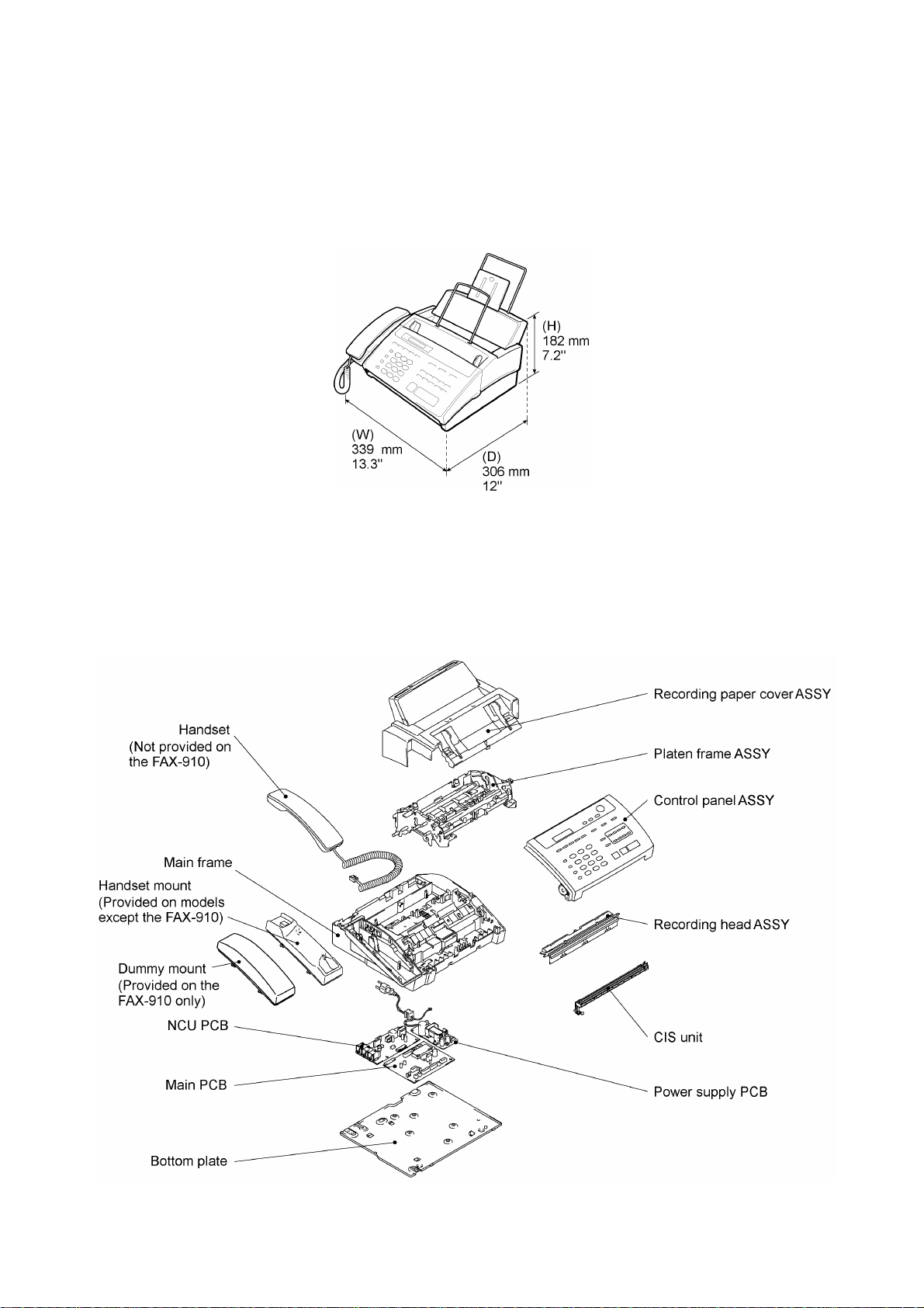
1.1 External Appearance and Weight
The figure below shows the equipment appearance and approximate dimensions.
Weight: Machine proper (excluding a ribbon cartridge) Approx. 4 kg (8.82 lbs.)
In package Approx. 6 kg (13.23 lbs.)
1.2 Components
The equipment consists of the following major components:
I - 1
Page 7

2. SPECIFICATIONS
Model Name FAX750 FAX770
Engine Thermal transfer Thermal transfer
Color Black (1395) White (1397)
Transmission Speed (sec) 15 15
Modem Speed (bps) 9600 9600
Group Compatibility G3 G3
Input/Output Width 8.5"/8.5" 8.5"/8.5"
ADF (pages) 10 10
Recording Paper Loadable 100 sheets 100 sheets
Ribbon Life (Letter-size print) 250 pages (77 m) 250 pages (77 m)
Starter Ribbon Life (Letter-size print) 100 pages (30 m) 100 pages (30 m)
LCD Size 16 x 1 16 x 1
On-Screen Programming Yes Yes
Super Fine Yes Yes
Smoothing Yes Yes
Gray Scale (levels) 64 by Dithered 64 by Dithered
One Touch 8 8
Speed Dial 40 40
Telephone Index Yes Yes
Speaker Phone Monitor Monitor
Handset Yes Yes
FAX/TEL Switch Yes Yes
Distinctive Ring Detection* Yes Yes
Caller ID* Yes Yes
Call Waiting Caller ID* Yes Yes
TAD Interface Yes Yes
Enhanced Remote Activation Yes Yes
Automatic Redial Yes Yes
Next-FAX Reservation Yes Yes
Multi-Resolution Transmission Yes Yes
Polling Type Std/Seq Std/Seq
Delayed Transmission 1-timer 1-timer
Call Reservation Yes Yes
Electronic Coverpage Yes - Super Yes - Super
Call Back Message Yes Yes
Activity Report Yes Yes
TX Verification Report Yes Yes
Memory Capacity (pages) 512 KB (20 pages) 512 KB (20 pages)
ECM Yes Yes
Broadcasting Yes Yes
Quick-Scan Yes Yes
Out-of-Paper Reception Yes Yes
Multi-Copying w/ Sorting Yes Yes
Enlargement/Reduction Ratio Yes (50-150%) Yes (50-150%)
Multi-Transmission No No
Confidential Mailbox No No
Auto Reduction Yes Yes
Message Center No No
TAD Recording Time No No
Fax Forwarding/Paging No Yes
Fax Retrieval No Yes
Fax-/Voice-on-demand No No
Fax & Voice Mailbox No No
Help List Yes Yes
Missing Link/Multifunction Link Ready Ready
Optional Memory No No
Voice Alarm No No
Others
* Check your local telephone company for availability of this service.
I - 2
Page 8

Model Name FAX870MC MFC970MC
Engine Thermal transfer Thermal transfer
Color White (1397) White (1138)
Transmission Speed (sec) 9 9
Modem Speed (bps) 14,400 14,400
Group Compatibility G3 G3
Input/Output Width 8.5"/8.5" 8.5"/8.5"
ADF (pages) 10 10
Recording Paper Loadable 100 sheets 100 sheets
Ribbon Life (Letter-size print) 250 pages (77 m) 250 pages (77 m)
Starter Ribbon Life (Letter-size print) 100 pages (30 m) 100 pages (30 m)
LCD Size 16 x 1 16 x 1
On-Screen Programming Yes Yes
Super Fine Yes Yes
Smoothing Yes Yes
Gray Scale (levels) 64 by Dithered 64 by Dithered
One Touch 8 8
Speed Dial 40 40
Telephone Index Yes Yes
Speaker Phone Full duplex (digital) Full duplex (digital)
Handset Yes Yes
FAX/TEL Switch Yes Yes
Distinctive Ring Detection* Yes Yes
Caller ID* Yes Yes
Call Waiting Caller ID* Yes Yes
TAD Interface Yes Yes
Enhanced Remote Activation Yes Yes
Automatic Redial Yes Yes
Next-FAX Reservation Yes Yes
Multi-Resolution Transmission Yes Yes
Polling Type Std/Seq Std/Seq
Delayed Transmission 1-timer 1-timer
Call Reservation Yes Yes
Electronic Coverpage Yes - Super Yes - Super
Call Back Message Yes Yes
Activity Report Yes Yes
TX Verification Report Yes Yes
Memory Capacity (pages) 512 KB (20 pages) 512 KB (20 pages)
ECM Yes Yes
Broadcasting Yes Yes
Quick-Scan Yes Yes
Out-of-Paper Reception Yes Yes
Multi-Copying w/ Sorting Yes Yes
Enlargement/Reduction Ratio Yes (50-150%) Yes (50-150%)
Multi-Transmission No No
Confidential Mailbox No No
Auto Reduction Yes Yes
Message Center Yes Yes
TAD Recording Time 15 minutes 15 minutes
Fax Forwarding/Paging Yes Yes
Fax Retrieval Yes Yes
Fax-/Voice-on-demand Voice-on-demand Voice-on-demand
Fax & Voice Mailbox Yes Yes
Help List Yes Yes
Missing Link/Multifunction Link Ready Included
Optional Memory No No
Voice Alarm No No
Others
* Check your local telephone company for availability of this service.
I - 3
Page 9

Model Name FAX-910 FAX-920/921
Engine Thermal Transfer Thermal Transfer
Color Black(1395) Black(1395)/White(1397/1138)
Transmission Speed (sec) 15 15
Modem Speed (bps) 9600 9600
Group Compatibility G3 G3
Input/Output Width 8.5"/8.5" 8.5"/8.5"
ADF (pages) 10 10
Recording Paper Loadable 100 sheets 100 sheets
Ribbon Life (A4-size print) 235 pages 235 pages
Starter Ribbon Life (A4-size print) 90 pages (30 m) 90 pages (30 m)
LCD Size 16 X 1 16 X 1
On-Screen Programming Yes Yes
Super Fine Yes Yes
Smoothing Yes Yes
Gray Scale (levels) 64 by Dithered 64 by Dithered
One Touch 16 w/SHIFT KEY 16 w/SHIFT KEY
Speed Dial 32 32
Telephone Index Yes Yes
Speaker Phone Monitor Monitor
Handset No Yes
FAX/TEL Switch Yes Yes
Caller ID Yes HOL/SWE/UK/FRA/NOR Yes HOL/SWE/UK/FRA/NOR
Call Waiting Caller ID No No
Distinctive Ringing No No
TAD Interface Yes Yes
Enhanced Remote Activation Yes Yes
Automatic Redial Yes Yes
Next-FAX Reservation Yes Yes
Multi-Resolution Transmission Yes Yes
Polling Type Sim/Sec/Del/Seq Sim/Sec/Del/Seq
Delayed Transmission 3-timer 3-timer
Call Reservation Yes Yes
Electronic Coverpage Yes - Super Yes - Super
Call Back Message Yes Yes
Journal Report Yes Yes
TX Verification Report Yes Yes
Memory Capacity (pages) 512KB (20 pages) 512KB (20 pages)
ECM Yes Yes
Broadcasting Yes Yes
Quick-Scan Yes Yes
Out-of-Paper Reception Yes Yes
Multi-Copying w/Sorting Yes Yes
Enlargement/Reduction Ratio Yes (50-150%) Yes (50-150%)
Multi-Transmission Yes Yes
Confidential Mailbox No No
Auto Reduction Yes Yes
Message Manager No No
TAD Recording Time No No
Fax Forwarding/Paging Yes - Only Fax forwarding Yes - Only Fax forwarding
Fax Retrieval Yes Yes
Fax-/Voice-on-demand No No
Fax & Voice Mailbox No No
Help List Yes Yes
MFL PRO for Fax Ready Ready
Optional Memory No No
Memo Manager No No
Mute Key No Yes-music on hold; Green Sleeves
Backup for Clock 9 hours 9 hours
Output Tray Option (CT70) Option (CT70)
Backup for Page Memory No No
I - 4
Page 10

Model Name FAX-930/931 MFC-925
Engine Thermal Transfer Thermal Transfer
Color Black(1395)/White(1397/1138) White(1138)
Transmission Speed (sec) 9 15
Modem Speed (bps) 14,400 9600
Group Compatibility G3 G3
Input/Output Width 8.5"/8.5" 8.5"/8.5"
ADF (pages) 10 10
Recording Paper Loadable 100 sheets 100 sheets
Ribbon Life (A4-size print) 235 pages 235 pages
Starter Ribbon Life (A4-size print) 90 pages (30 m) 90 pages (30 m)
LCD Size 16X1 16X1
On-Screen Programming Yes Yes
Super Fine Yes Yes
Smoothing Yes Yes
Gray Scale (levels) 64 by Dithered 64 by Dithered
One Touch 16 w/SHIFT KEY 16 w/SHIFT KEY
Speed Dial 32 32
Telephone Index Yes Yes
Speaker Phone Full duplex (digital) Monitor
Handset Yes Yes
FAX/TEL Switch Yes Yes
Caller ID Yes HOL/SWE/UK/FRA/NOR Yes HOL/SWE/UK/FRA/NOR
Call Waiting Caller ID No No
Distinctive Ringing No No
TAD Interface Yes Yes
Enhanced Remote Activation Yes Yes
Automatic Redial Yes Yes
Next-FAX Reservation Yes Yes
Multi-Resolution Transmission Yes Yes
Polling Type Sim/Sec/Del/Seq Sim/Sec/Del/Seq
Delayed Transmission 3-timer 3-timer
Call Reservation Yes Yes
Electronic Coverpage Yes - Super Yes - Super
Call Back Message Yes Yes
Journal Report Yes Yes
TX Verification Report Yes Yes
Memory Capacity (pages) 512KB (20 pages) 512KB (20 pages)
ECM Yes Yes
Broadcasting Yes Yes
Quick-Scan Yes Yes
Out-of-Paper Reception Yes Yes
Multi-Copying w/Sorting Yes Yes
Enlargement/Reduction Ratio Yes (50-150%) Yes (50-150%)
Multi-Transmission Yes Yes
Confidential Mailbox No No
Auto Reduction Yes Yes
Message Manager Yes No
TAD Recording Time 15 minutes No
Fax Forwarding/Paging Yes - both Yes - Only Fax forwarding
Fax Retrieval Yes Yes
Fax-/Voice-on-demand Voice-on-demand No
Fax & Voice Mailbox Yes No
Help List Yes Yes
MFL PRO for Fax Ready Included
Optional Memory No No
Memo Manager No No
Mute Key Yes-music on hold; Green SleevesYes-music on hold; Green Sleeves
Backup for Clock 15 hours 9 hours
Output Tray Option (CT70) Option (CT70)
Backup for Page Memory 6 hours No
I - 5
Page 11

CHAPTER II.
INSTALLATION
Page 12

CHAPTER III.
THEORY OF OPERATION
Page 13

CONTENTS
1. OVERVIEW...............................................................................................................III-1
2. MECHANISMS..........................................................................................................III-2
2.1 Transmitting Mechanism (Feeding and scanning documents).........................III-2
2.1.1 Automatic document feeder (ADF)...........................................................III-2
2.1.2 Scanner.....................................................................................................III-3
2.2 Receiving Mechanism (Feeding paper and printing data).................................III-4
2.3 Power Transmission Mechanism......................................................................III-5
2.3.1 Structure of the gear train.........................................................................III-5
2.3.2 Description of planetary gear system........................................................III-6
2.3.3 Power transmission for four operation modes..........................................III-7
2.3.4 Power transmission route..........................................................................III-14
2.4 Sensors and Actuators......................................................................................III-16
3. CONTROL ELECTRONICS......................................................................................III-19
3.1 Configuration.....................................................................................................III-19
3.2 Main PCB..........................................................................................................III-20
3.3 NCU PCB..........................................................................................................III-22
3.4 Control Panel PCB............................................................................................III-24
3.5 Power Supply PCB............................................................................................III-25
Page 14
1. OVERVIEW
*Not provided on the FAX-910.
III - 1
Page 15
2. MECHANISMS
The facsimile equipment is classified into the following mechanisms:
n Transmitting Mechanism Feeding and scanning documents
n Receiving Mechanism Feeding paper and printing data
n Power Transmission Mechanism Switching the power transmission route
n Sensors and Actuators
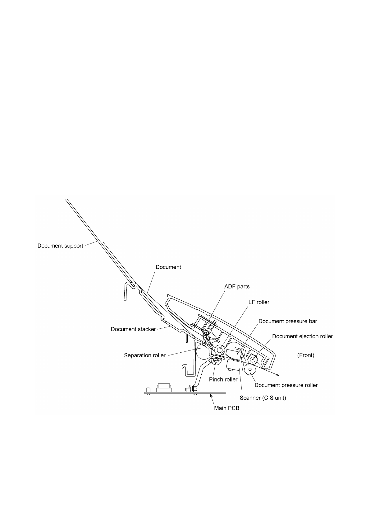
2.1 Transmitting Mechanism (Feeding and scanning documents)
The transmitting mechanism consists of the document stacker, automatic document feeder (ADF),
document feeding related rollers, scanner, and document sensors. (For details about the sensors,
refer to Section 2.4.)
For the drive power source, refer to Section 2.3.
2.1.1 Automatic document feeder (ADF)
If the operator sets documents on the stacker and starts the transmitting operation, the ADF
(consisting of the separation roller and ADF parts) feeds those documents into the equipment,
starting from the bottom sheet to the top, page by page. Each document advances to the scanner
with the LF roller, and then it is fed with the document ejection roller.
III - 2
Page 16

2.1.2 Scanner
The scanner uses a contact image sensor (CIS) unit which consists of an LED array illuminating
documents, a self-focus lens array collecting the reflected light, a CIS PCB carrying out
photoelectric conversion to output picture element data, and a cover glass on which a document
advances. When the document passes between the document pressure bar and the cover glass, it
is scanned.
III - 3
Page 17
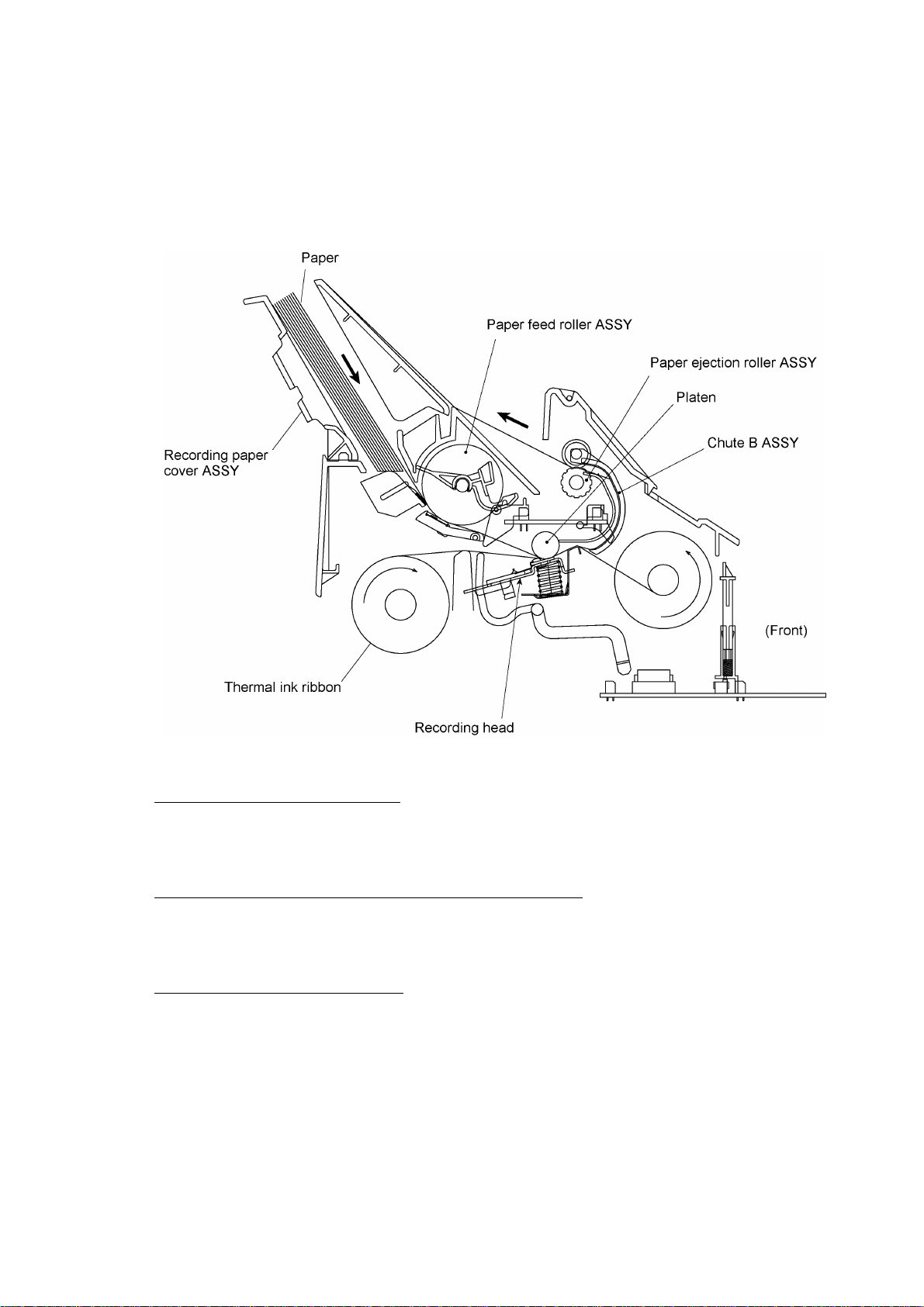
2.2 Receiving Mechanism (Feeding paper and printing data)
The receiving mechanism consists of the recording paper cover ASSY, paper feed roller ASSY,
platen, thermal recording head, paper ejection roller, and sensors. (For details about the sensors,
refer to Section 2.4.)
STEP 1: In the paper feeding mode
If the equipment receives data, the control electronics activates the solenoid and rotates the motor
counterclockwise to drive the paper feed roller (and paper ejection roller). This pulls in a sheet of
paper and feeds it until its leading edge reaches the point just before the printing position.
STEP 2: In the recording (platen drive & ribbon take-up) mode
The control electronics deactivates the solenoid and rotates the motor clockwise to drive the platen
gear and the ribbon take-up gear as well as the paper ejection roller. This feeds the paper up to the
printing position where the thermal recording head prints, as well as feeding the thermal ink ribbon.
STEP 3: In the paper ejection mode
The same operation as for STEP 1 takes place so as to eject the paper.
III - 4
Page 18
2.3 Power Transmission Mechanism
The equipment has a single drive motor whose power transmission route can be switched by the
planetary gear systems and the solenoid. This switching allows the equipment to function in four
operation modes (scanning, paper feeding/ejecting, recording, and copying modes). For the details
about the planetary gear systems, refer to Subsection 2.3.2.
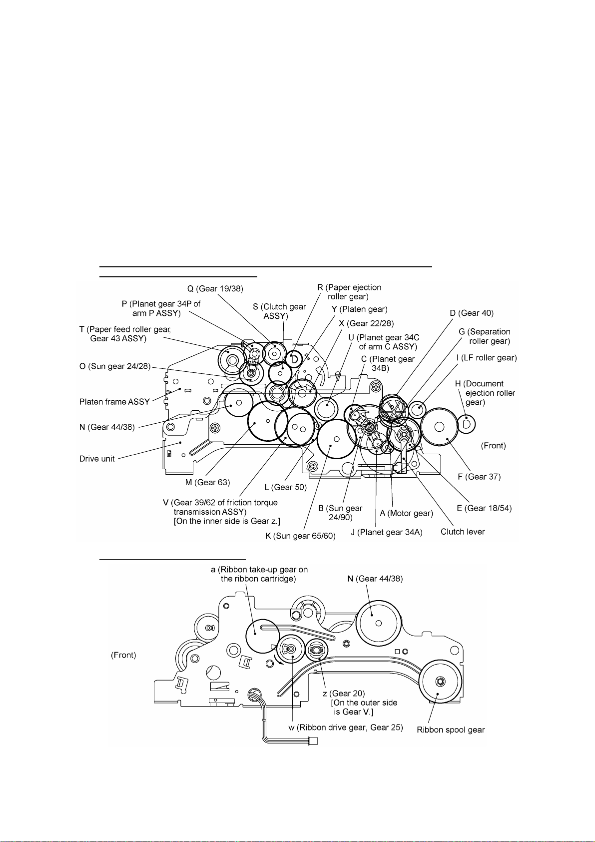
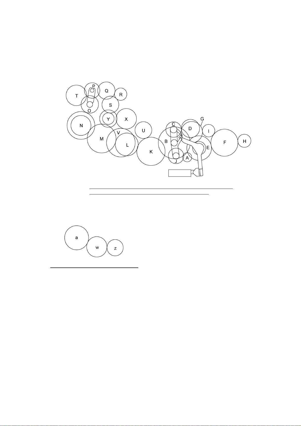
2.3.1 Structure of the gear train
All of the motor and gears are located at the left side of the equipment. As illustrated in the figure
below (On the outer side of the drive unit), the rotational torque of the motor on the drive unit is
transmitted via the gears on the drive unit to the gears on the main frame, to those on the control
panel ASSY, and to those on the platen frame.
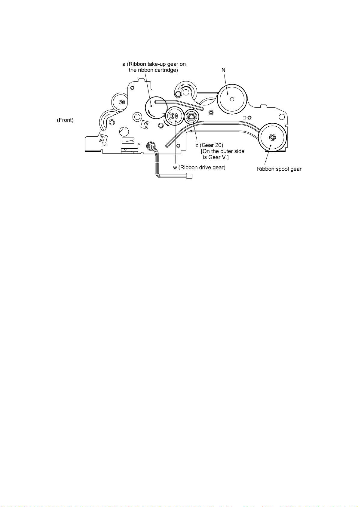
If gear 39/62 of the friction torque transmission ASSY ("V" in the figure below) rotates, gear 20 ("z")
on the inner side of the drive unit also rotates. The rotational torque is further transmitted to the
ribbon drive gear ("w") which drives the ribbon take-up gear ("a") on the ribbon cartridge, as shown
in the figure below (On the inner side of the drive unit).
On the outer side of the drive unit and on the left sides of the platen frame,
main frame and control panel ASSY
On the inner side of the drive unit
Gear Train
III - 5
Page 19
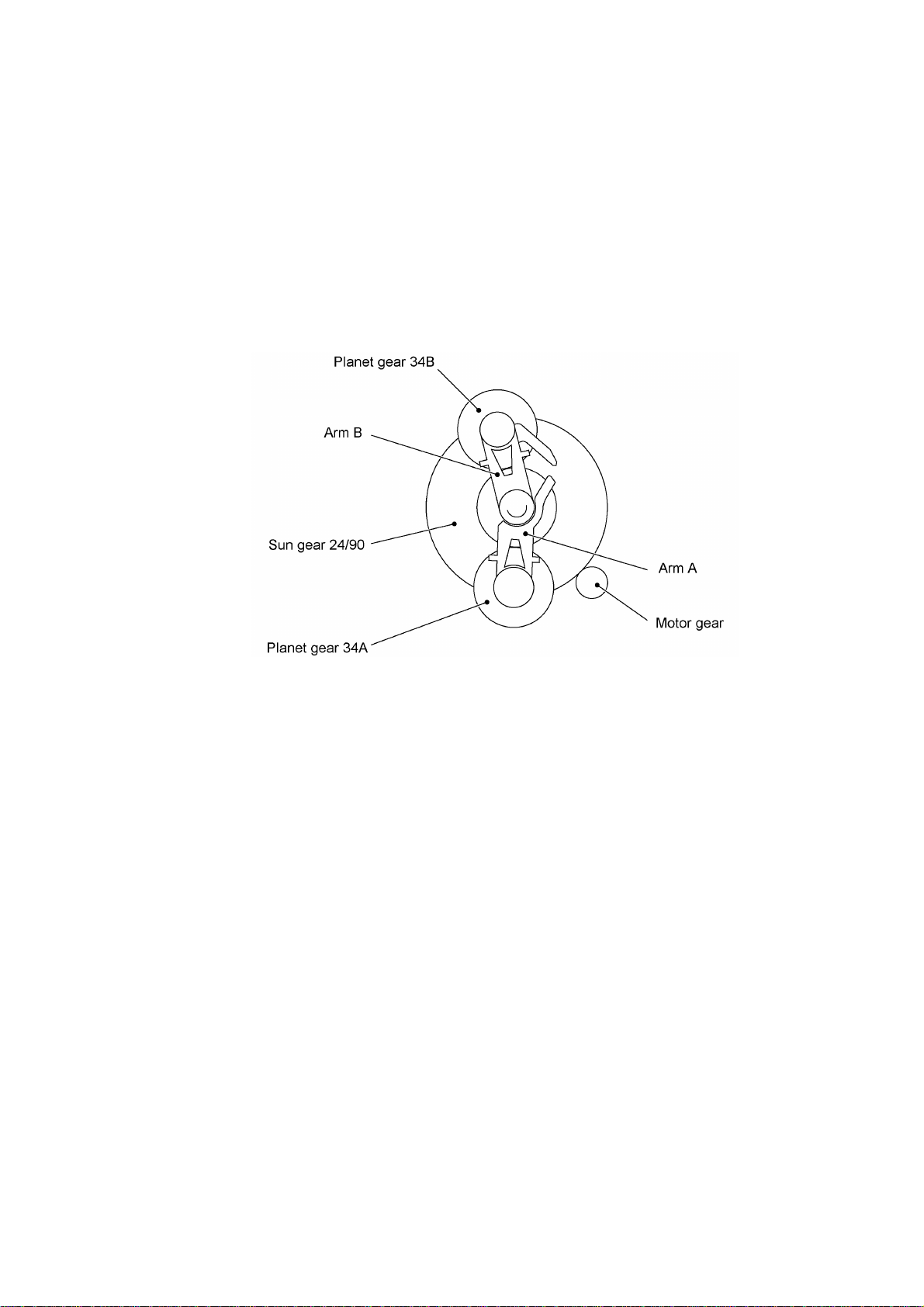
2.3.2 Description of planetary gear system
The equipment uses the following three planetary gear systems:
- Sun gear 24/90 ("B" in the figure given on the previous page) and its planet gears
- Sun gear 65/60 ("K") and its planet gear
- Sun gear 24/28 ("O") and its planet gear
This section describes the planetary gear system of sun gear 24/90 ("B"). It consists of sun gear
24/90, two planet gears 34, arm A, and arm B as shown below.
Planetary Gear System
If the motor rotates, sun gear 24/90 rotates so that the rotational torque is transmitted to the
engagement between the sun gear and planet gears 34. Since the arms and planet gears are so
designed that the moment of the arms is less than that of the planet gears, the arms turn around
the center shaft in the same direction as sun gear 24/90.
If the planet gear(s) becomes engaged with any other gear so that the arm cannot turn furthermore,
the rotational torque of sun gear 24/90 is transmitted to that planet gear. Accordingly, the planet
gear starts rotation in the opposite direction of sun gear 24/90.
III - 6
Page 20
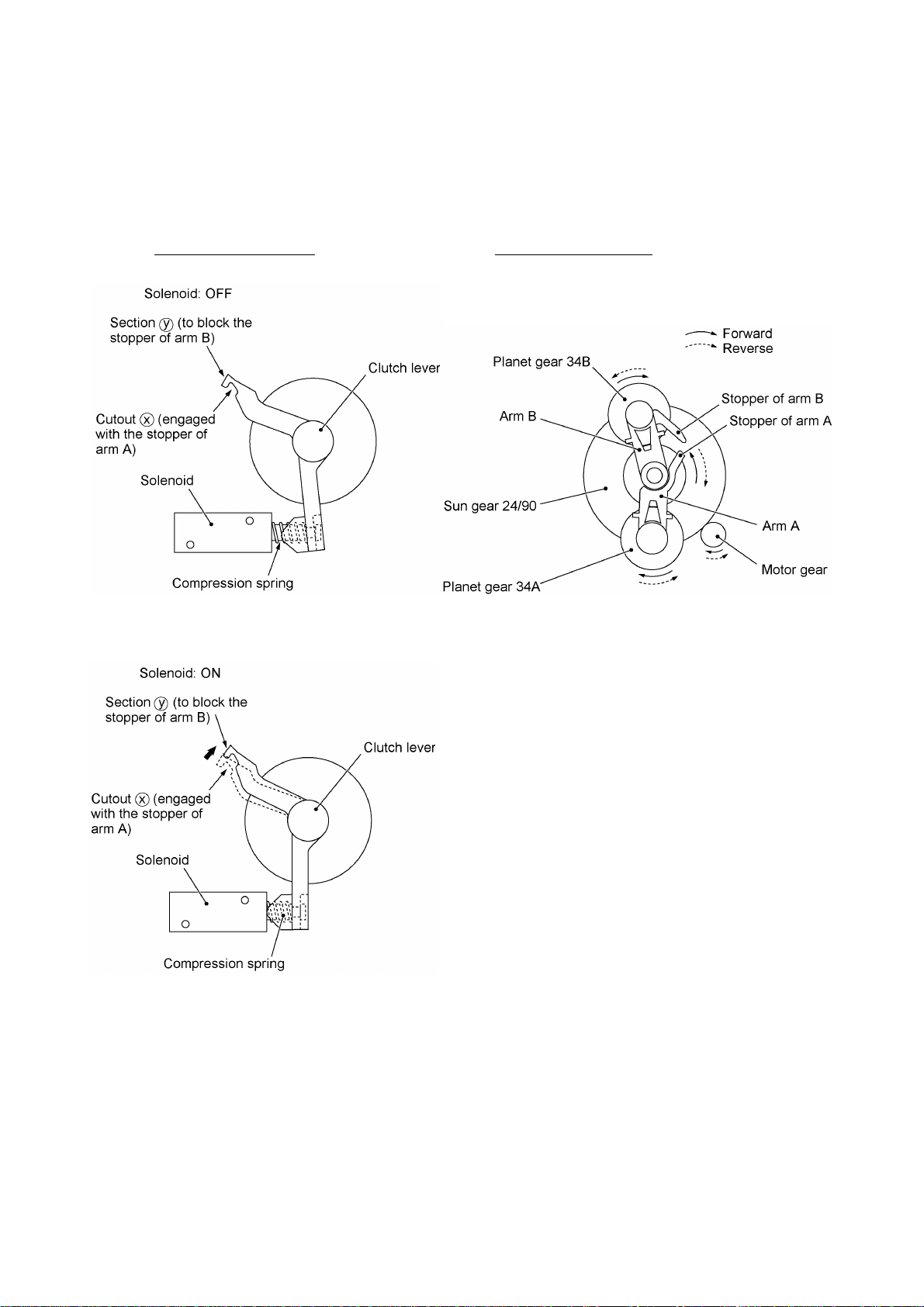
2.3.3 Power transmission for four operation modes
Depending upon the solenoid ON/OFF state and the motor rotation direction, the planetary gear
train switches the power transmission route for the four operation modes.
Solenoid ON/OFF state Motor rotation direction
III - 7
Page 21
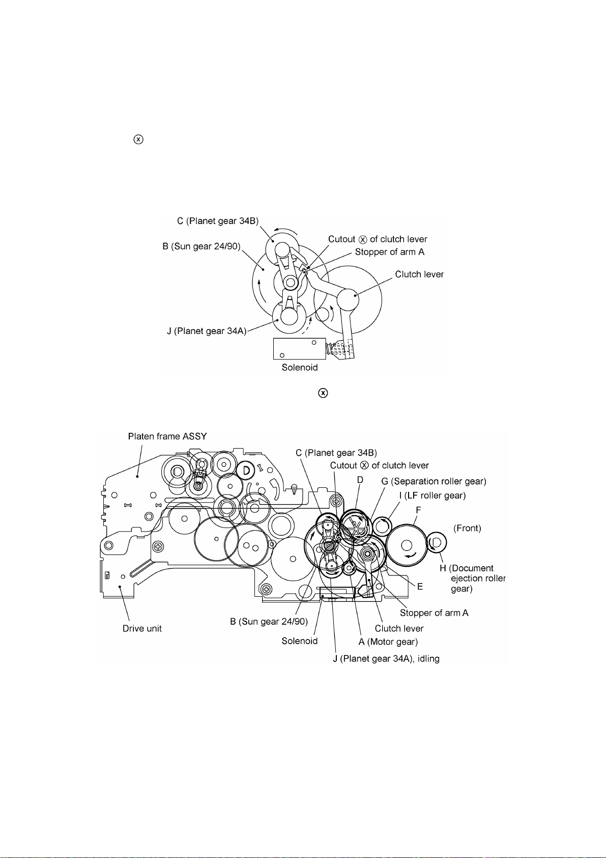
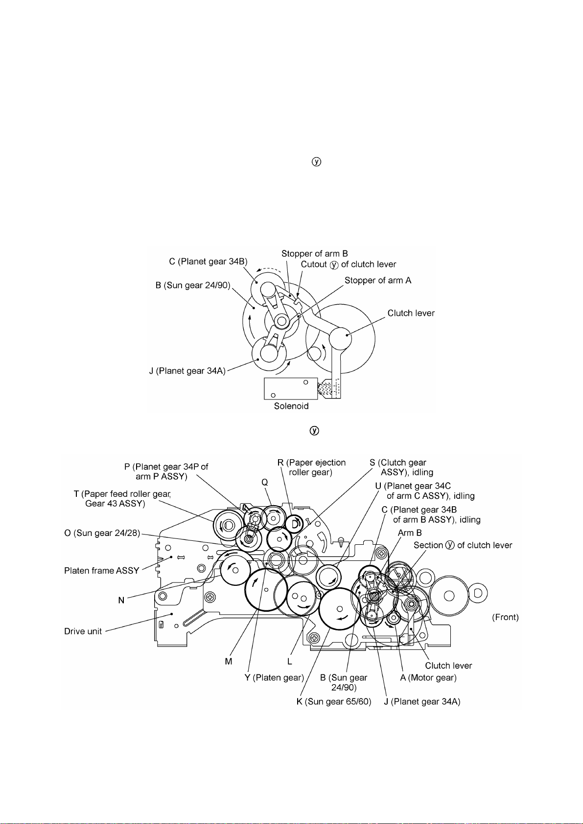
[ 1 ] Scanning mode (Solenoid: OFF, Motor rotation: Reverse)
In the scanning mode, the control electronics deactivates the solenoid. When the motor rotates in
the reverse direction, the clutch lever turns counterclockwise with the compression spring so that its
cutout becomes engaged with the stopper of arm A. Once arm A is locked, planet gear 34A
("J") will not be engaged with any other gear but simply idle.
The motor's rotational torque turns sun gear 24/90 ("B") clockwise so that planet gear 34B ("C")
transmits the torque via gear "D" to gear "E" which drives the separation roller gear ("G") and gear
"F." As gear "F" rotates, the LF roller gear ("I") and document ejection roller gear ("H") also rotate.
Arm A Locked by Cutout of Clutch Lever
Active Gears
III - 8
Page 22
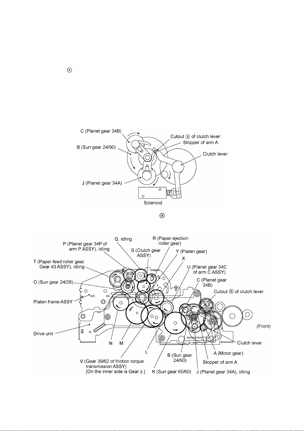
[ 2 ] Paper feeding/ejecting mode (Solenoid: ON, Motor rotation: Reverse)
In the paper feeding/ejecting mode, the control electronics activates the solenoid to release the
stopper of arm A. When the motor rotates in the reverse direction, sun gear 24/90 ("B") rotates
clockwise so that planet gear 34A ("J") transmits the torque via sun gear 65/60 ("K") and other
gears to the paper feed roller gear ("T") and paper ejection roller gear ("R").
Since the stopper of arm B is blocked by section of the clutch lever, the planet gear 34B ("C") is
merely idle without engaging with any other gear.
The rotational torque of the paper ejection roller gear ("R") is transmitted to the inner gear of the
clutch gear ASSY ("S"). However, the outer gear does not rotate since it is engaged with the platen
gear ("Y") that undergoes the heavy frictional torque of the platen. (This clutch gear ASSY works as
a one-way clutch. If the outer gear is driven by the platen gear ("Y"), the inner gear also rotates.
Refer to [ 3 ] Recording mode.)
Arm B Blocked by Section of Clutch Lever
Active Gears
III - 9
Page 23
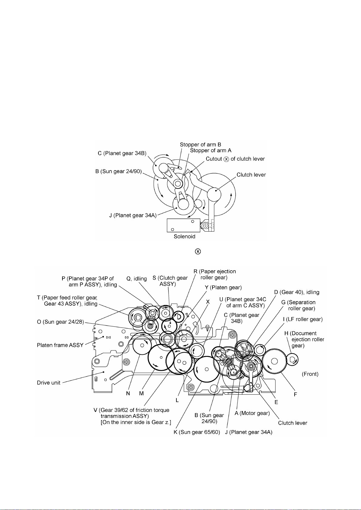
[ 3 ] Recording mode (Solenoid: OFF, Motor rotation: Forward)
In the recording mode, the control electronics deactivates the solenoid. When the motor rotates in
the forward direction, the clutch lever turns counterclockwise with the compression spring so that its
cutout becomes engaged with the stopper of arm A. Once arm A is locked, planet gear 34A
("J") will not be engaged with any other gear but simply idle.
The motor's rotational torque turns sun gear 24/90 ("B") counterclockwise so that planet gear 34B
("C") transmits the torque via sun gear 65/60 ("K") and other gears to the platen gear ("Y") and the
paper ejection roller gear ("R").
If gear 39/62 ("V") of the friction torque transmission ASSY rotates, gear 20 ("z") on the inner side of
the drive unit also rotates so as to drive the ribbon drive gear ("w") that rotates the ribbon take-up
gear ("a") on the ribbon cartridge, as shown on the next page.
Arm A Locked by Cutout of Clutch Lever
Active Gears on the Outer Side of the Drive Unit and Left Side of the Platen Frame
III - 10
Page 24

Active Gears on the Inner Side of the Drive Unit
III - 11
Page 25
[ 4 ] Copying mode (Solenoid: ON, Motor rotation: Forward)
In the copying mode, the control electronics activates the solenoid to release the stopper of arm A
from the clutch lever. When the motor rotates in the forward direction, sun gear 24/90 ("B") rotates
counterclockwise so that planet gear 34A ("J") transmits the torque to the document scanner
mechanism (e.g., the separation roller gear ("G"), LF roller gear ("I") and document ejection roller
gear ("H")) and planet gear 34B ("C") transmits the torque to the recording mechanism (e.g., platen
gear ("Y") and paper ejection roller gear ("R")).
If gear 39/62 ("V") rotates, gear 20 ("z") on the inner side of the drive unit also rotates so as to drive
the friction torque transmission ASSY and ribbon drive gear ("w") that rotates ribbon take-up gear
("a") on the ribbon cartridge, as shown on the next page.
Arm A Released from Cutout of Clutch Lever
Active Gears on the Outer Side of the Drive Unit and on the Left Sides of the Platen Frame,
Main Frame and Control Panel ASSY
III - 12
Page 26
Active Gears on the Inner Side of the Drive Unit
III - 13
Page 27
2.3.4 Power transmission route
Rotation of the motor gear is transmitted as shown below.
Gears on the outer side of the drive unit and on the left sides of
the platen frame, main frame and control panel ASSY
Gears on the inner side of the drive unit
A: Motor gear O: Sun gear 24/28
B: Sun gear 24/90 P: Planet gear 34P
C: Planet gear 34B Q: Gear 19/38
D: Gear 40 R: Paper ejection roller gear
E: Gear 18/54 S: Clutch gear ASSY
F: Gear 37 T: Paper feed roller gear, Gear 43 ASSY
G: Separation roller gear U: Planet gear 34C
H: Document ejection roller gear V: Friction torque transmission ASSY (Gear 39/62)
I: LF roller gear w: Ribbon drive gear (Gear 25)
J: Planet gear 34A X: Gear 22/28
K: Gear 65/60 Y: Platen gear (Gear 25/27)
L: Gear 50 z: Gear 20
M: Gear 63 a: Ribbon take-up gear on the ribbon cartridge
N: Gear 44/38
III - 14
Page 28
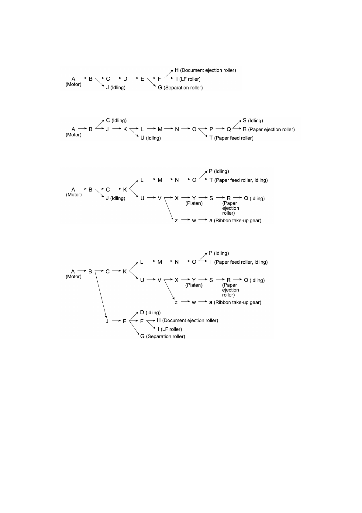
[ 1 ] Scanning Mode (Solenoid: OFF, Motor rotation: reverse)
[ 2 ] Paper Feeding/Ejecting Mode (Solenoid: ON, Motor rotation: reverse)
[ 3 ] Recording Mode (Solenoid: OFF, Motor rotation: forward)
[ 4 ] Copying Mode (Solenoid: ON, Motor rotation: forward)
III - 15
Page 29
2.4 Sensors and Actuators
This equipment has five photosensors and two mechanical switches as described below.
Sensor name Type Located on
Document front sensor Photosensor Control panel PCB ASSY
Document rear sensor Photosensor (PI2) Main PCB
Paper-edge sensor Photosensor (PH1) Sensor PCB
Paper ejection sensor Photosensor (PH2) Sensor PCB
Ribbon sensor Photosensor (PI1) Main PCB
Cover sensor Mechanical switch (SW1) Main PCB
Hook switch sensor* Mechanical switch (SW1) Hook switch PCB
• Document front sensor which detects the presence of documents.
• Document rear sensor which detects the leading and trailing edges of pages to tell the control
circuitry when the leading edge of a new page has reached the starting position and when the
scan for that page is over.
• Paper-edge sensor which detects the leading and trailing edges of paper and the presence of
paper as well as detecting whether the paper front cover is closed.
• Paper ejection sensor which detects whether a paper jam has occurred.
• Ribbon sensor which detects whether the ink ribbon is loaded.
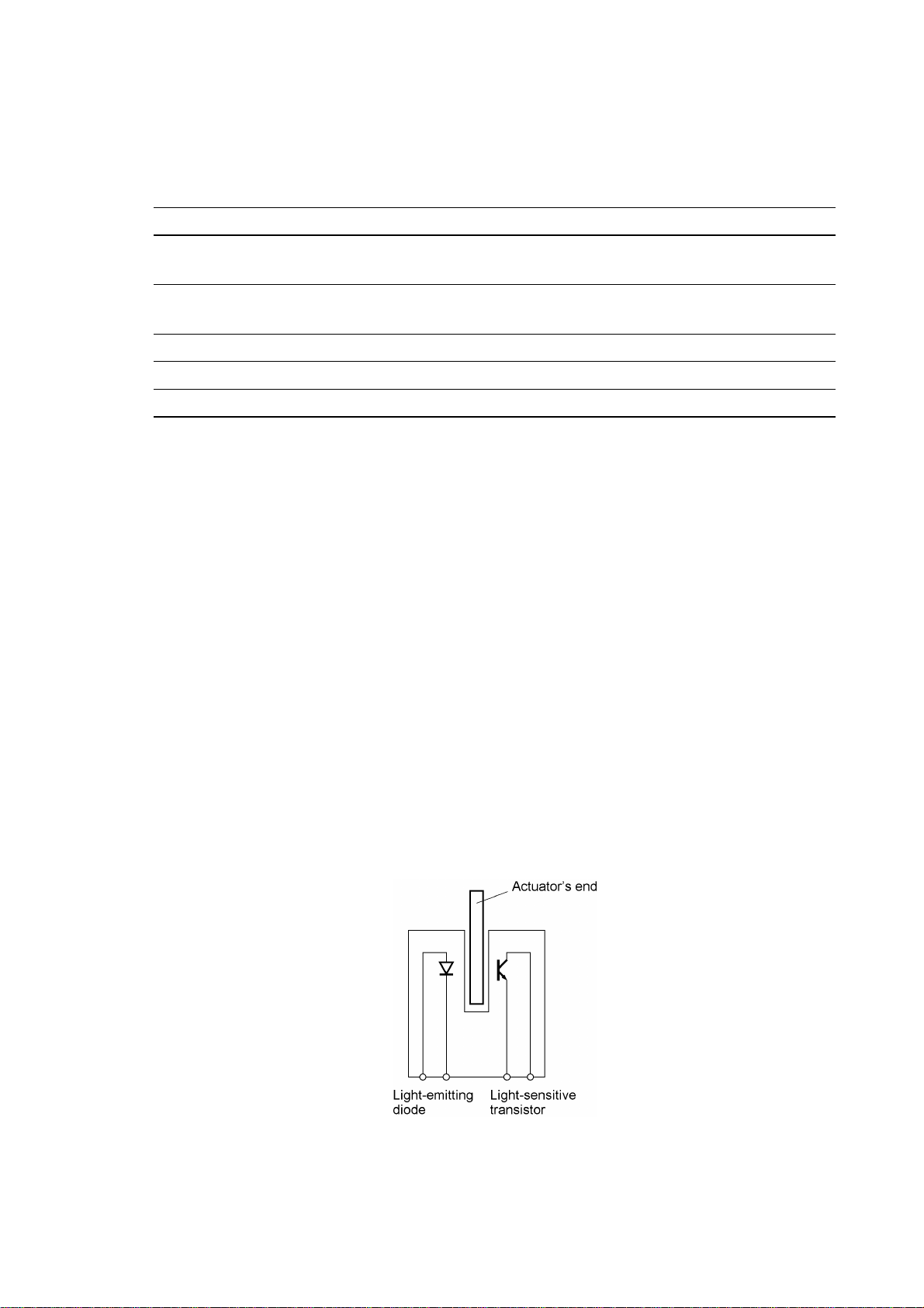
These photosensors are a photointerrupter consisting of a light-emitting diode and a light-sensitive
transistor. Each of them has an actuator separately arranged (see the following pages) except that
the paper-edge sensor has two actuators for sensing the paper and the paper front cover. When
an actuator is not activated, its black end lies in the path of light issued from the light-emitting diode
and interrupts its light so that the emitted light does not enter the light-sensitive transistor. If a
document, paper, or ribbon comes in so as to activate the actuator, the actuator's black end goes
out of the light path and the emitted light enters the light-sensitive transistor. This way, the sensor
detects the presence of documents, paper, or ink ribbon.
• Cover sensor which detects whether the recording paper cover ASSY is closed.
• Hook switch sensor* which detects whether the handset is placed on the handset mount.
The cover sensor has an actuator ASSY (consisting of two actuators and a spring). If you open the
recording paper cover ASSY, the actuator ASSY pops up to release the sensor.
*Not provided on the FAX-910.
III - 16
Page 30
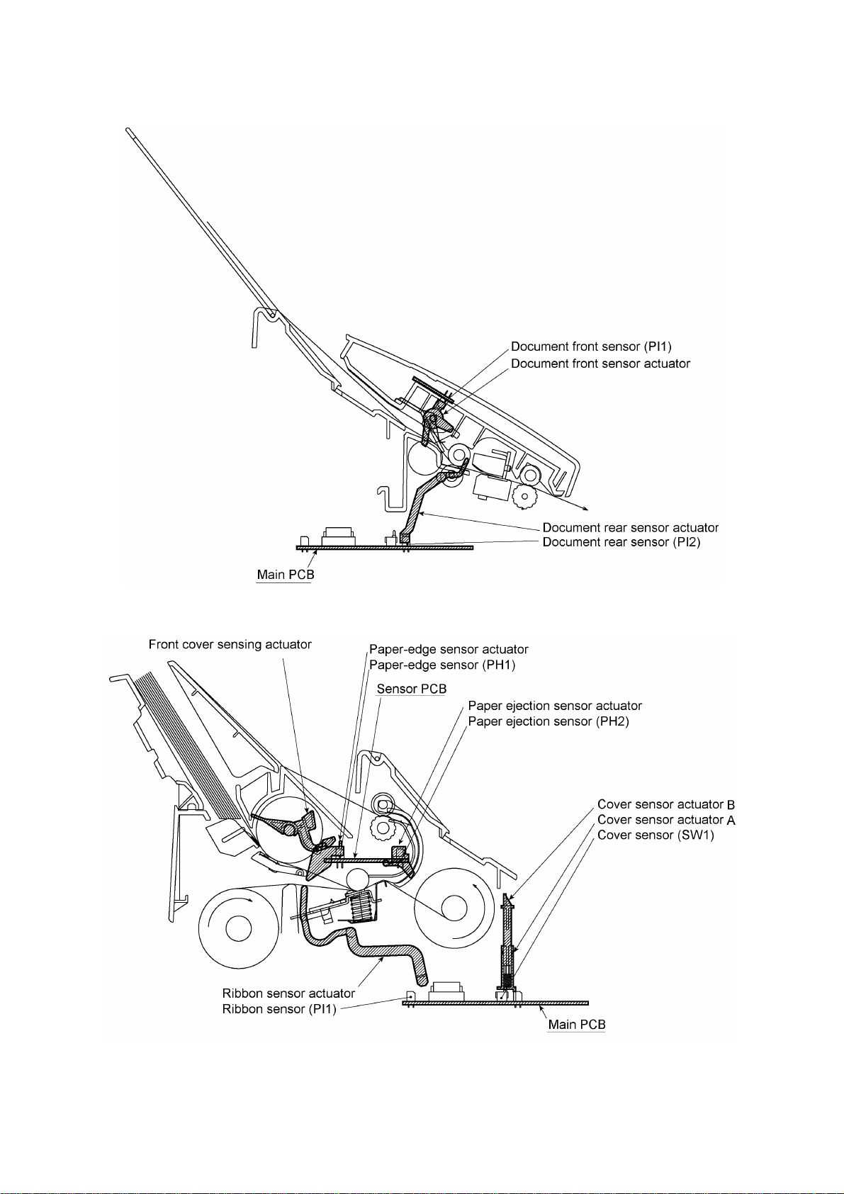
Location of Sensors and Actuators (1)
III - 17
Page 31

Location of Sensors and Actuators (2)
*Not provided on the FAX-910.
III - 18
Page 32

3. CONTROL ELECTRONICS
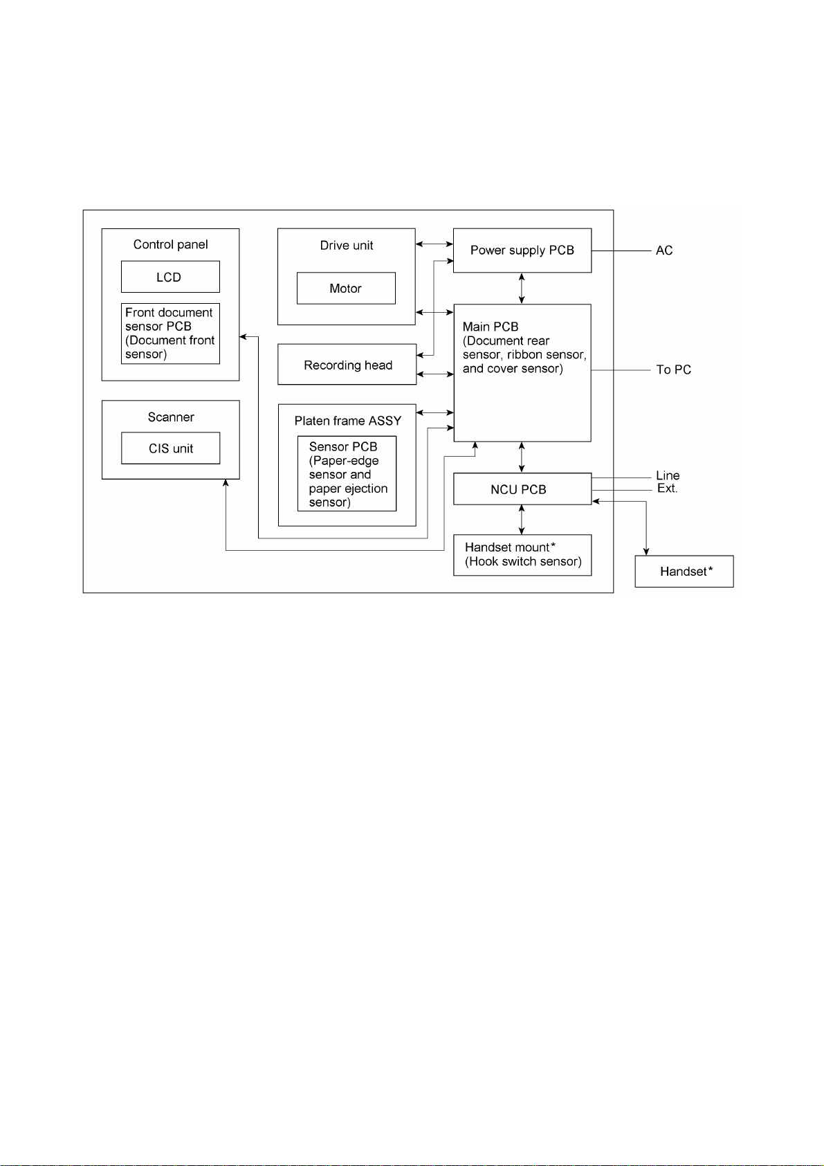
3.1 Configuration
The hardware configuration of the facsimile equipment is shown below.
*Not provided on the FAX-910.
*1 On the main PCB are these sensors:
l Ribbon sensor (PI1)
l Document rear sensor (PI2)
l Cover sensor (SW1)
*2 On the front document sensor PCB is the front document
sensor.
*3 On the sensor PCB are these sensors:
l Paper-edge sensor (PH1)
l Paper ejection sensor (PH2)
*4 On the hook switch PCB* is the hook switch sensor (SW1).
Configuration of Facsimile Equipment
III - 19
Page 33

3.2 Main PCB
The main PCB, which is the nucleus controlling the entire operation of the equipment, consists of a
FAX engine (ASIC), memories, motor drive circuitry, sensor detection circuitry, and analog circuits
for scanning, recording, and power transmission shifting.
*Provided on the FAX870MC/FAX-930/FAX-931/MFC970MC.
EEPROM:Electrically Erasable Programmable Read-only Memory
DRAM: Dynamic Random Access Memory
Block Diagram of Main PCB
III - 20
Page 34

FAX750/FAX770/FAX-910/FAX-920/FAX-921/MFC-925
FAX870MC/FAX-930/FAX-931/MFC970MC
III - 21
Page 35

3.3 NCU PCB
The NCU PCB switches the communications line to telephone or built-in MODEM, under the control
of the main PCB.
U.S.A. versions
III - 22
Page 36

European versions
NOTE: For models equipped with a power failure phone, the circuit
enclosed in a dotted line does not apply and points A and B are short
circuited together.
III - 23
Page 37

3.4 Control Panel PCB
The control panel PCB and the main PCB communicate with each other by serially transmitting
commands and data.
The control panel unit consists of a gate array, an LCD and LEDs, which are controlled by the gate
array according to commands issued from the FAX engine on the main PCB.
The calendar clock is backed up by the backup circuit on the main PCB.
The panel FPC is a flexible keyboard PCB which integrates the key matrix having rubber keytops.
Control Panel PCB and its Related Circuit
III - 24
Page 38

3.5 Power Supply PCB
The power supply uses the switching regulator to generate DC power (+25V, +6.5V, and +5V) from
a commercial AC power line.
The +25V source is stabilized and fed to the motor and solenoid (for feeding documents, recording
paper, and ink ribbon), recording head, the main PCB, and the CIS LED array.
The +6.5V source is not stabilized and fed to the Ni-MH battery (on the FAX870MC/FAX-930/FAX931/MFC970MC). The +5V source is fed to the logic on the main PCB, control panel, recording
head, and sensors.
Power Supply Circuit
III - 25
Page 39

CHAPTER IV.
DISASSEMBLY/REASSEMBLY,
LUBRICATION AND ADJUSTMENT
Page 40

CONTENTS
1. DISASSEMBLY/REASSEMBLY...............................................................................IV-1
n Safety Precautions..................................................................................................IV-1
Tightening Torque List............................................................................................IV-2
n Preparation..............................................................................................................IV-3
n How to Access the Object Component...................................................................IV-3
n Disassembly Order Flow.........................................................................................IV-4
1.1 ROM Cover, Battery ASSY* and Ribbon Shaft Stopper.....................................IV-5
1.2 Control Panel ASSY............................................................................................IV-7
1.3 Panel Rear Cover and Control Panel.................................................................IV-9
1.4 LF Roller ASSY and CIS Unit.............................................................................IV-14
1.5 Head Protector, Recording Head ASSY, Head Adjuster, and Recorder
Frame.................................................................................................................IV-18
1.6 Recording Paper Cover ASSY and Paper Guides*............................................IV-22
1.7 Lock Levers, Chute B ASSY, Gears, Paper Ejection Roller, Paper Feed
Roller ASSY, Pressure Plate, Paper Feed Chute and Other Components on
the Platen Frame................................................................................................IV-23
1.8 Cover Stopper and Platen Frame ASSY............................................................IV-34
1.9 Bottom Plate.......................................................................................................IV-36
1.10 Power Supply PCB, Main PCB, and NCU PCB..................................................IV-37
1.11 Speaker, PC I/F Modular ASSY, and Ribbon Shaft Stopper Spring...................IV-40
1.12 Drive Unit, Motor, and Main-Head Harness........................................................IV-41
1.13 Panel-lock Leaf Springs......................................................................................IV-42
1.14 Cover Sensor Actuators and Pinch Roller..........................................................IV-43
1.15 Document Rear Sensor Actuator, Separation Roller, and Ribbon Sensor
Actuator..............................................................................................................IV-44
1.16 Handset Mount,* Hook Switch PCB,* and Dummy Mount**...............................IV-45
1.17 Harness Routing.................................................................................................IV-46
2. LUBRICATION..........................................................................................................
[ 1 ] Control panel ASSY....................................................................................IV-47
[ 2 ] LF roller ASSY............................................................................................IV-49
[ 3 ] Platen frame ASSY.....................................................................................IV-49
[ 4 ] Separation roller and main frame...............................................................IV-51
IV-47
Page 41

1. DISASSEMBLY/REASSEMBLY
nn Safety Precautions
To prevent the creation of secondary problems by mishandling, observe the following precautions
during maintenance work.
(1) Unplug the power cord from the power outlet before replacing parts or units. When having
access to the power supply, be sure to unplug the power cord from the power outlet.
(2) Be careful not to lose screws, washers, or other parts removed for parts replacement.
(3) When using soldering irons and other heat-generating tools, take care not to damage the resin
parts such as wires, PCBs, and covers.
(4) Before handling the PCBs, touch a metal portion of the equipment to discharge static
electricity; otherwise, the electronic parts may be damaged due to the electricity charged in
your body.
(5) When transporting PCBs, be sure to wrap them in conductive sheets such as aluminum foil.
(6) Be sure to reinsert self-tapping screws correctly, if removed.
(7) Tighten screws to the torque values listed on the next page.
(8) When connecting or disconnecting cable connectors, hold the connector bodies not the cables.
If the connector has a lock, always slide the connector lock to unlock it.
(9) Before reassembly, apply the specified lubricant to the specified points. (Refer to Section 2 in
this chapter.)
(10)After repairs, check not only the repaired portion but also that the connectors and other related
portions function properly before operation checks.
IV - 1
Page 42

Tightening Torque List
Location Screw type Q'ty Tightening torque Loosening torque
(kg•cm) (kg•cm)
ADF parts Taptite, pan (washer) B M3x6 1 4 ±2 Min. 1
Panel rear cover Taptite, cup B M3x8 2 4 ±2 Min. 1.5
Document front sensor PCB Taptite, cup B M2.6x6 1 4 ±2 Min. 1
Control panel PCB* Taptite, cup B M2.6x6 1 4 ±2 Min. 1
LF leaf spring Taptite, bind B M3x8 1 5 ±2 Min. 2
CIS holders Taptite, bind B M3x8 2 4 ±1 Min. 2
CIS unit Taptite, pan B M3x8 1 5 ±2 Min. 2
Recorder frame Taptite, cup B M3x8 2 5 ±2 Min. 2
Recording paper cover ASSY Shoulder screw 2 7 ±2 Min. 3
Paper feed chute Taptite, cup S M3x6 2 5 ±2 Min. 4
Cover stopper Taptite, cup B M3x8 1 5 ±2 Min. 1.5
Bottom plate Taptite, cup B M3x8 7 5 ±2 Min. 1.5
Grounding terminal Screw, pan (washer) M4x6DB 1 7 ±2 Min. 4
Motor Screw, pan (washer) M3x6DB 1 7 ±2 Min. 3.5
* The control panel PCB of the FAX870MC/FAX-930/FAX-931/MFC970MC is secured with a screw.
IV - 2
Page 43

nn Preparation
Prior to proceeding to the disassembly procedure,
(1) Unplug
- the modular jack of the telephone line,
- the modular jack of the curled cord (and remove the handset), and
- the modular jack of an external telephone set if connected. (Not shown below.)
(2) Remove
- the document wire extension,
- the paper wire extension,
- the paper support, and
- the ribbon cartridge.
nn How to Access the Object Component
• On the next page is a disassembly order flow which helps you access the object components.
To remove the separation roller, for example, first find it on the flow and learn its number ( in
this case). You need to remove parts numbered , , , , , , and so as to access the
separation roller.
• Unless otherwise specified, the disassembled parts or components should be reassembled in
the reverse order of removal.
IV - 3
Page 44

nn Disassembly Order Flow
IV - 4
Page 45

1.1 ROM Cover, Battery ASSY* and Ribbon Shaft Stopper
(1) Open the control panel ASSY to the front.
(2) Pull up the lock levers and open the recording paper cover ASSY to the rear.
(3) As shown below, insert the tip of the spring hook at the center or right half of the locking arm
(when viewed from the front), then lift up the hook to release and move the ROM cover to the
right.
(4) FAX870MC/FAX-930/FAX-931/MFC970MC: To replace the battery ASSY (Ni-MH battery),
plug the power cord of the facsimile equipment into a wall socket, disconnect the battery
harness from the main PCB, and take out the battery ASSY from the main frame. Set a new
battery ASSY and unplug the power cord.
Disconnecting the battery harness with the power cord unplugged will lose the settings (e.g.,
calendar clock, voice messages, and received FAX data) stored in the RAM.
If you do not need to replace the battery ASSY, take out the battery ASSY from the main frame
and put it on the main PCB with the battery harness being connected.
(*FAX870MC/FAX-930/FAX-931/MFC970MC)
IV - 5
Page 46

(5) Remove the ribbon shaft stopper by pushing down the rear end of the stopper lightly with a
screwdriver.
nn Reassembling Notes
• When reinstalling the ribbon shaft stopper, lightly push down the ribbon shaft stopper spring with
the rear end of the ribbon shaft stopper and then set the stopper.
IV - 6
Page 47

1.2 Control Panel ASSY
(1) Open the control panel ASSY to the front.
(2) Push the right arm of the panel rear cover outward (in the direction of arrow •) to release it
from the boss provided on the main frame, then move the control panel ASSY to the left and
push the left arm outward (in the direction of arrow ‚).
(3) Remove the harness holder by unhooking its latches from the panel rear cover with a flat
screwdriver as shown below.
IV - 7
Page 48

(4) Disconnect the panel-main harness.
IV - 8
Page 49

1.3 Panel Rear Cover and Control Panel
(1) Place the control panel ASSY upside down.
If you do not need to remove the ADF parts, document pressure bar, or document ejection
roller, skip to step (6).
(2) To remove the ADF parts (spring covers, spring plates, and separation rubber), remove the
screw.
(3) To remove the document pressure bar ASSY, pull either of the supports provided on the panel
rear cover outwards and lift up the pressure bar. The spring also comes off.
IV - 9
Page 50

(4) To disassemble the document pressure bar ASSY, first remove the white film.
NOTE: Once removed, the white film will become unusable and a new one will have to be put
back in.
Next, place the document pressure bar ASSY with the pressure bar support facing up for
easier disassembly. While pressing the boss of the document pressure bar with the tip of a
Phillips screwdriver, shift the document pressure bar to the right to take it off from the pressure
bar support.
IV - 10
Page 51

(5) To remove the document ejection roller, push the arm rib to the rear and shift the document
ejection roller to the right.
Pull out the document ejection roller gear and remove gear 37.
Pull out the document ejection roller to the left.
Remove the bearing.
(6) Remove the two screws from the panel rear cover. (See the next page.)
(7) Unhook the panel rear cover from the four "X" latches provided on the control panel and lift up
the panel rear cover.
(8) Remove the document front sensor actuator from the panel rear cover by turning it clockwise
(in the direction of arrow •) and moving it in the direction of arrow ‚.
(9) Remove the screw from the document front sensor PCB.
(10)FAX750/FAX770/FAX-910/FAX-920/FAX-921/MFC-925: Unhook the control panel PCB from
the two "Y" latches.
FAX870MC/FAX-930/FAX-931/MFC970MC: Remove the screw from the control panel PCB
and unhook the PCB from the two "Y" latches. Disconnect the microphone.
IV - 11
Page 52

IV - 12
Page 53

(11)To remove the LCD, unhook the four "Z" latches of the LCD holder from the control panel PCB.
Unlock the LCD cable connector and disconnect the LCD flat cable. Slide the LCD to the cable
side and remove it from the LCD holder.
NOTE: Do not take out the LCD except when the LCD is defective and requires replacement.
(12)Unlock the FPC key connector and disconnect the FPC key.
nn Reassembling Notes
• A new LCD is covered with a protection sheet. Before installing it, remove the protection sheet.
• As shown below, route the LCD flat cable and set the LCD holder on the control panel PCB.
• Before reinstalling the control panel PCB to the control panel, wipe fingerprints off the LCD
surface with a soft cloth.
• After assembling the document pressure bar and its support together, check that the boss of the
document pressure bar is fitted in the hole provided in the support.
• After reinstalling the assembly of the document pressure bar and its support to the control panel
ASSY, attach the white film, referring to the illustration given on page IV-10.
IV - 13
Page 54

1.4 LF Roller ASSY and CIS Unit
(1) Take off the LF leaf spring by removing the screw.
(2) Push the arm rib to the rear and shift the LF roller ASSY to the left. The bearing also comes
off.
IV - 14
Page 55

(3) Peel off the black CIS film.
NOTE: Once removed, the CIS film will become unusable and a new one will have to be put
back in.
IV - 15
Page 56

(4) Remove screw "a" from the CIS holder L.
(5) Lift up the left end of the CIS unit slightly and disengage the CIS holder R from the hooks
provided of the main frame.
(6) Disconnect the CIS-main harness.
(7) Take off the CIS holders L and R by removing screws "b."
IV - 16
Page 57

(8) Push the latch to the rear and remove the document pressure rollers and their shaft.
(9) Remove the document pressure roller spring.
nn Reassembling Notes
• When attaching the CIS film, align its right and rear edges with the cutout provided in the main
frame, as illustrated on page IV-15.
• Before reinstalling the LF roller ASSY, apply grease to the left end of the ASSY. (Refer to
Section 2, "LUBRICATION.")
IV - 17
Page 58

1.5 Head Protector, Recording Head ASSY, Head Adjuster, and Recorder Frame
(1) Pull up the lock levers and open the recording paper cover ASSY to the rear.
(2) While pulling up the left end of the head protector, unhook latches • through „ in this order
with a small flat screwdriver as illustrated below.
IV - 18
Page 59

(3) Push down both ends of the recording head ASSY and move it to the rear to release the tabs
from the cutouts provided in the recorder frame.
(4) Disconnect the two harnesses (main-head harness and head-power harness) from the
recording head ASSY and then lift up the ASSY.
(5) Remove the three head springs.
IV - 19
Page 60

(6) Take off the recorder frame by removing the two screws.
(7) Remove the grounding spring.
(8) Take out the head-power harness from the hook provided on the main frame.
IV - 20
Page 61

(9) To replace the main frame with a new one, first check to see which position the head adjuster
is currently set in (see the three positions in the illustration below), and then remove the head
adjuster with a flat screwdriver. Next set it to the new main frame in the same position.
If the printed image is abnormally light or dark, remove the head adjuster and set it back in any
other position.
NOTE: Do not access the head adjuster unless necessary.
nn Reassembling Notes
• Before reinstalling the recorder frame, check its top end (on which paper and ribbon pass) for
scratches or burrs. Those on the top end will affect the printed image.
• When reinstalling the recording head ASSY, make sure that the three head springs are set into
place.
IV - 21
Page 62

1.6 Recording Paper Cover ASSY and Paper Guides*
(1) To remove the paper guides*, open the paper front cover towards you, then pull up the latch (in
the direction of arrow • in the illustration below) and pull the paper guide in the direction of
arrow ‚.
(2) Remove the two screws.
(3) Lift up the front of the recording paper cover ASSY and take it out to the rear.
(*Not provided on the U.S.A. and Canadian versions.)
nn Reassembling Notes
• To reinstall the paper guides*, first insert its top end and then push the guide into place.
• When reinstalling the recording paper cover ASSY, slightly slant it to the right and hook the
paper front cover's arm onto the pressure plate release cam as shown above while keeping the
paper front cover closed, then put the ASSY onto the platen frame.
After installation, open and close the paper front cover to check that the paper front cover is
interlocked with the pressure plate ASSY.
IV - 22
Page 63

1.7 Lock Levers, Chute B ASSY, Gears, Paper Ejection Roller, Paper Feed Roller ASSY, Pressure
Plate, Paper Feed Chute and Other Components on the Platen Frame
With the platen frame being secured to the main frame, you can remove and install the components
given in this section. To remove the platen frame itself, see Section 1.8.
(1) Open the platen frame ASSY.
(2) Turn the lock levers R and L to the rear and pull them out.
IV - 23
Page 64

(3) Pull the chute B ASSY up and towards you to unhook the upper latches from the platen frame,
then pull the ASSY down and towards you to unhook the lower latches.
IV - 24
Page 65

(4) At the left end of the platen frame, remove the gears in the following order:
- Platen gear (gear 25/27) by pulling its pawl outwards. (Also remove the black platen shaft
bushing L.)
- Arm P ASSY by pulling its pawl outwards.
- Gear 24/28 (sun gear)
- Clutch gear 37 ASSY by removing the retaining ring, together with gear 19/38
- Paper ejection roller gear
NOTE: The platen shaft bushing is greased for antistatic purpose. Take care not to stain
other parts with the grease.
(5) Remove the paper ejection roller.
IV - 25
Page 66

(6) Remove the front cover sensing actuator from the paper feed roller shaft by pulling up the
actuator's rear edge as shown below.
(7) At the right end of the paper feed roller ASSY (when viewed from the rear), remove the collar
stopper and gear 43 ASSY by removing the retaining ring.
(8) At the left end (when viewed from the rear), remove the pawled bushing by pulling its pawls
outwards.
Next, pull the paper feed roller shaft to the right until the left end of the shaft comes out of the
platen frame and then tilt the shaft to the right so that the bushing-fixed end can pass through
the lower hole, and take it out to the left.
IV - 26
Page 67

(9) Make sure that the platen is set in place, and then close the platen frame ASSY.
NOTE: If you close the platen frame ASSY when no platen is set and the recording head
ASSY is installed, the platen frame ASSY and the recording head ASSY will be locked
together.
(10)Fully turn the pressure plate release cam to the rear and pull it up and outwards to unhook from
the platen frame.
(11)Pull the latches provided on the pressure plate outwards and lift it up. The two springs also
come off.
IV - 27
Page 68

(12)Pull up the separation pad while squeezing it. The spring also comes off.
(13)Remove the paper-edge sensor actuator by pulling the support outwards.
IV - 28
Page 69

(14)To take the paper feed chute off the platen frame, do the following:
- Disconnect the main-sensor harness from the sensor PCB while pressing down the PCB
with your finger, then remove the harness guide and take out the harness from the cable
clamps.
NOTE: Pulling up the main-sensor harness without pressing down the sensor PCB will
cause the PCB to work out of the paper feed chute.
NOTE: Once removed, the harness guide will become unusable and a new one will have
to be put back in.
IV - 29
Page 70

- Remove the two screws and lift up the paper feed chute.
IV - 30
Page 71

(15)From the paper feed chute, remove the pressure plate link, paper ejection sensor actuator,
sensor PCB, and chute film.
NOTE: Once removed, the chute film will become unusable and a new one will have to be put
back in.
IV - 31
Page 72

IV - 32
Page 73

(16)Remove the platen as follows:
At the left end of the platen frame, remove the platen gear (gear 25/27) by pulling its pawl
outwards and then remove the platen shaft bushing L.
At the right end, remove the platen shaft bushing R by pulling its pawls outwards.
Move the platen to the left to take out the right end from the platen frame and then take it out to
the right.
CAUTION: After removing the platen, NEVER close the platen frame ASSY when the
recording head ASSY is set in place. Doing so will make the cutouts of the platen frame ASSY
catch the right and left ends of the recording head ASSY. The platen frame ASSY and the
recording head ASSY will be locked together.
NOTE: The platen shaft bushings are greased for antistatic purpose. Take care not to stain
other parts with the grease.
nn Reassembling Notes
• If you replace the platen shaft bushing(s) with new one(s), apply grease to it. (Refer to Section
2, "LUBRICATION."
• When reinstalling the platen shaft bushings R and L, fit boss "a" of each bushing into cutout "b"
provided in the platen frame. (See the above illustration.)
• When attaching the chute film, align its rear edge with the rib of the paper feed chute.
• When reinstalling the pressure plate, slide the ribs along the grooves of the paper feed chute
until the latches of the pressure plate catch the pressure plate link.
• When setting the lock levers back into place, as shown on page IV-23, first fit the shorter end of
the spring into the cutout provided in each lock lever, then fit the longer end of the spring and the
lock lever's boss into the small and large holes provided in the platen frame, respectively. Fully
turn the lever to the rear so that the lever's hooks catch the platen frame.
IV - 33
Page 74

1.8 Cover Stopper and Platen Frame ASSY
TIP: Only when you need to remove the platen frame from the main frame, remove the cover
stopper. When accessing other components, keep the cover stopper in place for easier handling.
(1) Remove the screw from the cover stopper.
(2) Lift up the rear end of the cover stopper and open the platen frame ASSY to remove the cover
stopper.
(3) Take out the cover stopper spring plate.
IV - 34
Page 75

(4) Remove the retaining ring (E5) from the left end of the platen frame and move the frame to the
left. The spring washer also comes off.
NOTE: Take care not to drop the retaining ring inside the main frame. If you drop it, you need
to remove the bottom plate to take it out.
IV - 35
Page 76

1.9 Bottom Plate
(1) Place the machine upside down.
(2) Remove the seven screws from the bottom plate.
(3) Slightly lift up the bottom plate and disconnect the grounding terminal.
(4) Remove the bottom plate together with the insulation sheet.
IV - 36
Page 77

1.10 Power Supply PCB, Main PCB, and NCU PCB
(1) Unhook the head-power harness from latch "B" (together with the PC I/F modular harness
since the head-power harness is routed under the PC I/F modular harness through the duct
when viewed from the bottom).
(2) Pull out the AC cord bushing from the main frame.
(3) Disconnect the power supply PCB from the main PCB.
(4) Slightly lift up the power supply PCB and disconnect the head-power harness.
(5) Slightly lift up the main PCB and NCU PCB together, then disconnect the NCU PCB from the
main PCB.
(6) Disconnect the following nine harnesses from the main PCB:
• Hook switch harness (Not provided on the FAX-910.)
• Speaker harness
• Panel-main harness
• PC I/F modular harness
• CIS harness
• Solenoid harness
• Motor harness
• Main-head harness
• Main-sensor harness
NOTE: The FAX870MC/FAX-930/FAX-931/MFC970MC has a Ni-MH battery ASSY. Only
when you need to replace the main PCB, disconnect the battery harness. After installing a new
main PCB, you may need to make settings to be stored in the RAM. If you need to replace the
battery ASSY, do not disconnect the harness in this disassembly step. Doing so with the power
cord unplugged will lose the settings stored in the RAM. Refer to Section 1.1.
(7) You may take out the harnesses (except for the main-head harness that is routed under the
drive unit) from the main frame.
IV - 37
Page 78

IV - 38
Page 79

nn Reassembling Notes
• When routing the harnesses, refer to Section 1.17.
• After you replace the main PCB, be sure to follow the flowchart given below.
IV - 39
Page 80

1.11 Speaker, PC I/F Modular ASSY, and Ribbon Shaft Stopper Spring
(1) Pull the speaker support spring to the right and lift up the speaker. The spring also comes off.
(2) Slightly lift up the main PCB (if mounted) and disconnect the speaker harness from the PCB.
(3) Unhook the PC I/F modular harness (which is routed through the duct) from latches “B” and
“A,” and then take out the modular.
(4) Slightly lift up the main PCB (if mounted) and disconnect the PC I/F modular harness from the
PCB.
(5) Slightly pull up the rear end of the ribbon shaft stopper spring and take it out to the rear.
IV - 40
Page 81

1.12 Drive Unit, Motor, and Main-Head Harness
(1) Slightly lift up the main PCB (if mounted), unhook the motor harness from latch "D," and
disconnect the harness from the PCB.
(2) Slightly lift up the main PCB (if mounted), unhook the solenoid harness from latches "E" and
“G” and the notch, then disconnect the harness from the PCB.
(3) Lift up the drive unit.
(4) Remove the motor from the drive unit by removing the screw.
(5) Slightly lift up the main PCB (if mounted) and disconnect the main-head harness from the PCB.
IV - 41
Page 82

1.13 Panel-lock Leaf Springs
(1) Remove the panel-lock leaf springs by pushing them up with your finger from the bottom.
IV - 42
Page 83

1.14 Cover Sensor Actuators and Pinch Roller
(1) Pull up the cover sensor actuator A and turn it to separate from the actuator B. The spring
pops up and the actuator B drops.
(2) Remove the harness guide film.
NOTE: This film is attached to the main frame with double-sided adhesive tape. This film can
be usable again as long as it is adhesive.
(3) Press the lock of each pinch roller spring and pull out the springs to the rear.
(4) Lift up the pinch roller.
IV - 43
Page 84

1.15 Document Rear Sensor Actuator, Separation Roller, and Ribbon Sensor Actuator
(1) Turn up the document rear sensor actuator to the front and pull it up.
(2) Push lock "a" (in the direction of arrow •) and pull the separation roller gear to the right (in the
direction of arrow ‚). Then take out the separation roller and its gear.
(3) To remove the ribbon sensor actuator, you need to disengage the recording head ASSY from
the recorder frame. (Refer to Section 1.5, (1) to (3).)
Push lock "b" to the rear, pinch the front end of the ribbon sensor actuator with your fingers,
pull the right end up and rightwards, turn the actuator counterclockwise 180°, and then take it
out of the main frame.
IV - 44
Page 85

1.16 Handset Mount,* Hook Switch PCB,* and Dummy Mount**
(*For models except the FAX-910, **For the FAX-910 only)
(1) Insert the tip of a flat screwdriver into the slits of the handset mount* (or the dummy mount**)
and unhook the mount from the main frame.
(2) To replace the hook switch PCB*, you need to disconnect the hook switch harness from the
main PCB. (Refer to Section 1.10.)
nn Reassembling Notes
• When reinstalling the handset mount* (or the dummy mount**), first align the left edge with the
main frame and then push down the right edge.
IV - 45
Page 86

1.17 Harness Routing
IV - 46
Page 87

2. LUBRICATION
Apply the specified lubricants to the lubrication points as shown below.
Molykote EM-30L or EM-30LG
For points , apply a rice-sized pinch of grease (6 mm3).
Floil GE-334C
For points , apply half of a rice-sized pinch of grease (3 mm3).
[ 1 ] Control panel ASSY
IV - 47
Page 88

IV - 48
Page 89

[ 2 ] LF roller ASSY
[ 3 ] Platen frame ASSY
IV - 49
Page 90

IV - 50
Page 91

[ 4 ] Separation roller and main frame
IV - 51
Page 92

CHAPTER V.
MAINTENANCE MODE
Page 93

CONTENTS
1. ENTRY INTO THE MAINTENANCE MODE............................................................V-1
2. LIST OF MAINTENANCE-MODE FUNCTIONS......................................................V-2
3. DETAILED DESCRIPTION OF MAINTENANCE-MODE FUNCTIONS..................V-4
3.1 EEPROM Parameter Initialization..................................................................V-4
3.2 Printout of Scanning Compensation Data......................................................V-5
3.3 ADF Performance Test...................................................................................V-7
3.4 Test Pattern 1.................................................................................................V-8
3.5 Firmware Switch Setting and Printout............................................................V-9
3.6 Operational Check of LCD.............................................................................V-50
3.7 Operational Check of Control Panel PCB.......................................................V-50
3.8 Sensor Operational Check.............................................................................V-52
3.9 Fine Adjustment of Scanning Start/End Position............................................V-53
3.10CIS Scanner Area Setting..............................................................................V-54
3.11EEPROM Customizing...................................................................................V-54
3.12Equipment Error Code Indication...................................................................V-55
3.13Output of Transmission Log to the Telephone Line.......................................V-55
3.14Document Draw Adjustment ..........................................................................V-56
Page 94

1. ENTRY INTO THE MAINTENANCE MODE
FAX750/FAX770/FAX870MC/MFC970MC: To make the facsimile equipment enter the
maintenance mode, press the Function, *, 2, 8, 6, and 4 keys in this order.
Within 2 seconds
FAX-910/FAX-920/FAX-921/FAX-930/FAX-931/MFC-925: To make the facsimile equipment enter
the maintenance mode, press the Menu, *, 2, 8, 6, and 4 keys in this order.
Within 2 seconds
The equipment beeps for approx. one second and displays " " on the
LCD, indicating that it is placed in the initial stage of the maintenance mode, a mode in which the
equipment is ready to accept entry from the keys.
To select one of the maintenance-mode functions listed in Section 2, enter the corresponding 2digit function code with the numerical keys on the control panel. (The details of each maintenancemode function are described in Section 3.)
NOTES: • Pressing the 9 key twice in the initial stage of the maintenance mode makes the
equipment exit from the maintenance mode, restoring it to the standby state.
• Pressing the Stop button after entering only one digit restores the equipment to the
initial stage of the maintenance mode.
• If an invalid function code is entered, the equipment resumes the initial stage of the
maintenance mode.
• The 98-year model displays " "; the earlier models display
" ."
V - 1
Page 95

2. LIST OF MAINTENANCE-MODE FUNCTIONS
Maintenance-mode Functions
Function
Code Function
01 EEPROM Parameter Initialization 3.1 (V-4)
02
03
04
05 Printout of Scanning Compensation Data 3.2 (V-5)
06
07
08 ADF* Performance Test 3.3 (V-7)
09 Test Pattern 1 3.4 (V-8)
10 Firmware Switch Setting 3.5 (V-9)
11 Printout of Firmware Switch Data 3.5 (V-49)
12 Operational Check of LCD 3.6 (V-50)
13 Operational Check of Control Panel PCB
32 Sensor Operational Check 3.8 (V-52)
54 Fine Adjustment of Scanning Start/End Position 3.9 (V-53)
55 CIS Scanner Area Setting 3.10 (V-54)
74 EEPROM Customizing 3.11 (V-54)
82 Equipment Error Code Indication 3.12 (V-55)
87 Output of Transmission Log to the Telephone Line 3.13 (V-55)
91 EEPROM Parameter Initialization (except the telephone number
99 Exit from the Maintenance Mode ---- (V-1)
----- Document Draw Adjustment 3.14 (V-56)
(Check of Keys and Buttons)
storage area)
Reference
Subsection
(Page)
3.7 (V-50)
3.1 (V-4)
V - 2
* ADF: Automatic document feeder
Page 96

- - - - - - - - - - - - - - - - - - - - - - - - - - IMPORTANT - - - - - - - - - - - - - - - - - - - - - - - - - - - - - - - -
Basically, the maintenance-mode functions listed on the previous page should be accessed by
service personnel only. However, you may allow end users to access some of these under the
guidance of service personnel (e.g., by telephone).
The user-accessible functions (codes 10, 11, 12, 82, 87 and 91) are shaded in the table given on
the previous page. Function code 10 accesses the firmware switches WSW01 to WSW36, each of
which has eight selectors. You should not allow end users to access all of those selectors, but you
may allow them to access user-accessible selectors which are shaded in the firmware switch tables
in Subsection 3.5.
The service personnel should instruct end users to follow the procedure given below.
(1) FAX750/FAX770/FAX870MC/MFC970MC: Press the Function and Mode keys in this order.
FAX-910/FAX-920/FAX-921/FAX-930/FAX-931/MFC-925: Press the Menu and Mode keys in
this order.
The LCD clears the current display.
NOTE: The Mode key is inoperable during standby for redialing and timer.
(2) Press the 0 key.
(3) Enter the desired function code (10, 11, 12, 82, 87, or 91) with the numerical keys.
For function code 10, access the desired firmware switch according to the operating procedure
described in Subsection 3.5.
(4) To make the equipment return to the standby state, press the Stop key.
FAX750/FAX770/FAX-910/FAX-920/FAX-921/MFC-925
FAX870MC/FAX-930/FAX-931/MFC970MC
V - 3
Page 97

3. DETAILED DESCRIPTION OF
MAINTENANCE-MODE FUNCTIONS
3.1 EEPROM Parameter Initialization
nn Function
The equipment initializes the parameters, user switches, and firmware switches registered in the
EEPROM, to the initial values. Entering the function code 01 initializes all of the EEPROM areas,
but entering 91 does not initialize some areas, as listed below.
Function code
Data item
Maintenance-mode functions
User switches
Firmware switches
Remote activation code
Activity report
Distinctive ringing patterns
registered
Station ID data
Outside line number
Cover page custom comments
Remote access code
FAX forwarding/paging
Personal mailbox password
Telephone function registration
One-touch dialing
Speed dialing
Group dialing
EEPROM customizing code
(4-digit)
01 91
These will be
initialized
All of these will be
initialized
These will not be
initialized
This will not be initialized.
(Note that the first digit of the 4-digit code will be
initialized to "0." If the code is 1001, for example, it will
be initialized to 0001.)
NOTE: If you replace the main PCB with one used for other facsimile equipment, carry out this
procedure and then customize the EEPROM (maintenance-mode function code 74 in Section 3.11).
nn Operating Procedure
(1) Press the 0 and 1 keys (or the 9 and 1 keys according to your need) in this order in the initial
stage of the maintenance mode.
The "PARAMETER INIT" will appear on the LCD.
(2) Upon completion of parameter initialization, the equipment returns to the initial stage of the
maintenance mode.
V - 4
Page 98

3.2 Printout of Scanning Compensation Data
nn Function
The equipment prints out the white and black level data for scanning compensation.
nn Operating Procedure
Do not start this function merely after powering on the equipment but start it after carrying out a
sequence of scanning operation. Unless the equipment has carried out any scanning operation,
this function cannot print out correct scanning compensation data. This is because at the start of
scanning operation, the equipment initializes white and black level data and takes in the scanning
compensation reference data.
(1) Press the 0 and 5 keys in this order in the initial stage of the maintenance mode.
The "WHITE LEVEL 1" will appear on the LCD.
(2) The equipment prints out the scanning compensation data list containing the following:
a) White level data (208 bytes)
b) Black level data (1 byte)
c) Initial clamp PWM value (1 byte)
d) Clamp PWM value (1 byte)
e) Compensation data for background color (1 byte)
f) Initial LED light intensity value (1 byte)
g) LED light intensity value (1 byte)
h) LED light intensity value on the white film of the document pressure bar ASSY and
documents (2 bytes)
i) Document rear sensor adjustment value (1 byte)
(3) Upon completion of recording of the compensation data list, the equipment returns to the initial
stage of the maintenance mode.
NOTE: If any data is abnormal, its code will be printed in inline style, as shown on the next page.
V - 5
Page 99

Scanning Compensation Data List
V - 6
Page 100

3.3 ADF Performance Test
nn Function
The equipment counts the documents fed by the automatic document feeder (ADF) and displays
the count on the LCD for checking the ADF performance.
nn Operating Procedure
(1) Set documents (Allowable up to the ADF capacity) in the initial stage of the maintenance
mode.
The "DOC. READY" will appear on the LCD.
(2) Press the 0 and 8 keys in this order.
The equipment
i) copies the 1st document and displays “COPY P.01 STD” on the LCD.
ii) feeds in and out the 2nd through 4th documents while counting without copying them as the
LCD shows the corresponding count,
iii) copies the 5th document and displays “COPY P.05 STD” on the LCD,
iv) feeds in and out the 6th through 9th documents while counting without copying them as the
LCD shows the corresponding count, and
v) copies the 10th document and displays “COPY P.10 STD” on the LCD.
(3) Upon completion of feeding in and out all of the documents, the final count appears on the
LCD.
(4) Press the Stop key to return the equipment to the initial maintenance mode.
V - 7
 Loading...