

Page 1

FACSIMILE EQUIPMENT
SERVICE MANUAL
MODEL: FAX100/570/615/625/635/675
FAX575M/715M/725M
FAX590DT/590MC/825MC/875MC
Page 2

© Copyright Brother 1995
All rights reserved.
No part of this publication may be reproduced in any
form or by any means without permission in writing
from the publisher.
Specifications are subject to change without notice.
Page 3

PREFACE
This publication is a Service Manual covering the specifications, construction, theory of operation, and maintenance of the Brother facsimile equipment. It includes information required for
field troubleshooting and repair—disassembly, reassembly, and adjustment—so that service
personnel will be able to understand equipment function, to rapidly repair the equipment and
order any necessary spare parts.
T o perform appropriate maintenance so that the facsimile equipment is always in best condition
for the customer, the service personnel must adequately understand and apply this manual.
This manual is made up of five chapters and appendices.
CHAPTER I
CHAPTER II
CHAPTER III. THEORY OF OPERATION
CHAPTER IV. INDICATION AND INFORMATION PRINTOUT OF ERROR
CHAPTER V. MAINTENANCE
APPENDICES Circuit Diagrams
.
GENERAL DESCRIPTION
.
INSTALLATION
This manual describes the model and its versions to be destined for major countries. The specifications
and functions are subject to change depending upon each destination.
Page 4

CHAPTER I.
GENERAL DESCRIPTION
Page 5

CONTENTS
1. EQUIPMENT OUTLINE................................................................................. I-1
1.1External Appearance.............................................................................. I-1
1.2Components............................................................................................I-1
2. SPECIFICATIONS..........................................................................................I-2
Page 6
1. EQUIPMENT OUTLINE
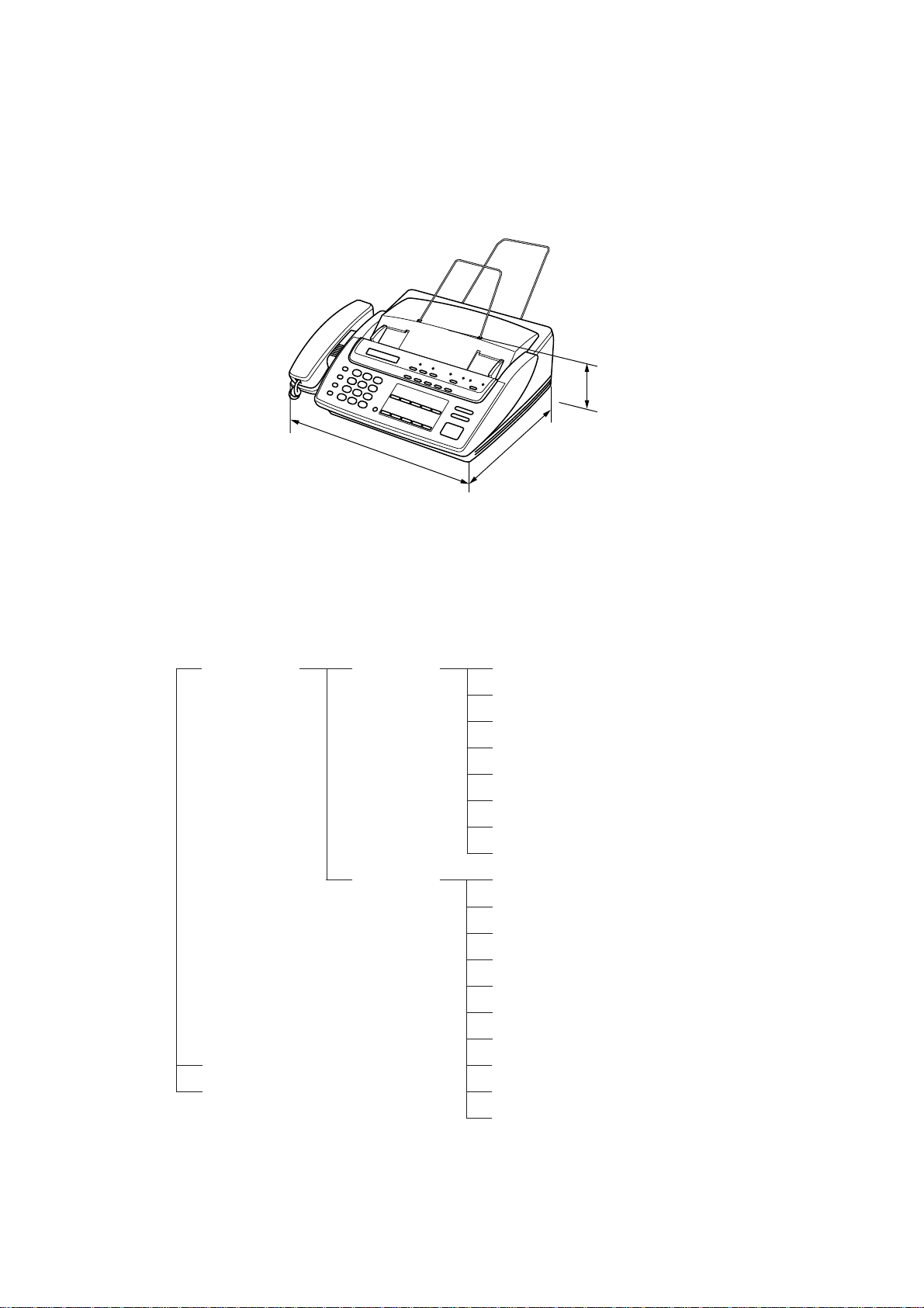
1.1 External Appearance
The figure below shows the equipment appearance and approximate dimensions.
121 (H)
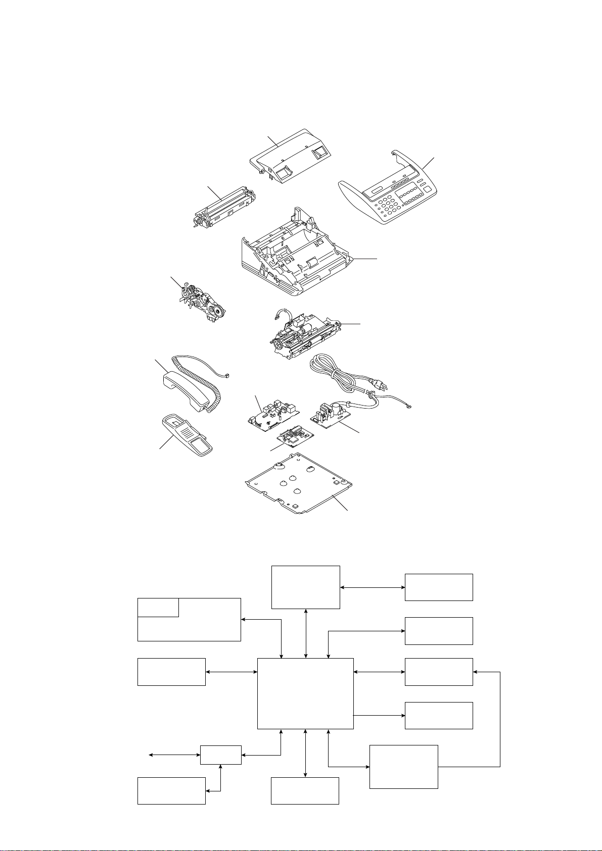
1.2 Components
The equipment has the following components:
Facsimile
Equipment
377 (W)
Electronic/
Electrical/
Section
Mechanical
Section
304 (D)
(Unit: mm)
Main PCB
NCU PCB
Control Panel PCB
Recording Head Unit
LED Array (for illuminating documents)
Charge Coupled Device (CCD) Unit
Sensors
Power Supply PCB
Recorder & Cutter Unit
CCD Unit
Drive Motor
Clutch Solenoid
(for paper & document feed and for cutter drive)
Package
Accessories
Drive Gears
Control Panel Unit
Covers
Automatic Document Feeder (ADF)
Handset
Frame and Miscellaneous Parts
I – 1
Page 7

2. SPECIFICATIONS
Model FAX100 FAX615 FAX625 FAX635 FAX675
Color 1138 BN4 BN2 BN4 BN2
Modem Speed 9600 bps 9600 bps 9600 bps 9600 bps 9600 bps
Coding Method MH MH MH MH MH
Transmission Speed 15 sec 15 sec 15 sec 15 sec 15 sec
CCITT Group G3 G3 G3 G3 G3
Input/Output Width 8.5"/8.5" 8.5"/8.5" 8.5"/8.5" 8.5"/8.5" 8.5"/8.5"
Auto Cutter Yes Yes Yes Yes Yes
ADF Capacity (pages) 15 15 15 15 15
Anti-curl System Yes Yes Yes Yes Yes
Paper Size
LCD Size 16 x 1 16 x 1 16 x 1 16 x 1 16 x 1
On-screen Programming Yes Yes Yes Yes Yes
Super Fine Yes Yes Yes Yes Yes
Smoothing Yes Yes Yes Yes Yes
Gray Scale 32 32 32 64 64
One-touch Dialing 10x2 10 10x2 10x2 10x2
Speed Dialing 20 30 20 30 40
Group Dialing No No No No No
Telephone Index No No No No No
Speakerphone Monitor Monitor Monitor Monitor Monitor
Fax/Tel Switch Yes Yes Yes Yes Yes
TAD Interface Yes Yes Yes Yes Yes
Enhanced Remote Activation Yes Yes Yes Yes Yes
Distinctive Ringing Yes Yes Yes Yes Yes
Next-Fax Reservation Yes No Yes Yes Yes
Help Yes Yes Yes Yes Yes
Caller ID No No No No Yes
Automatic Redialing Yes Yes Yes Yes Yes
Multi-Resolution Transmission Yes Y es Yes Yes Yes
Polling Std/Sec/Del Std/Sec/Del Std/Sec/Del Std/Sec/Del Std/Sec/Del
Delayed Transmission Yes, 1 timer Yes, 1 timer Yes, 1 timer Yes, 1 timer Yes, 1 timer
Coverpage Yes Yes Yes Yes Yes
Call Reservation Yes Yes Yes Yes Yes
Call Back Message Yes Yes Yes Yes Yes
Activity Report Yes Yes Yes Yes Yes
Transmission Verification Report Yes Yes Yes Yes Yes
Page Memory No No No No No
ECM No No No No No
Broadcasting No No No No No
Quick Scanning No No No No No
Out-of-Paper Reception No No No No No
Multi Copy No No No No No
Multi Transmission No No No No No
TAD T ype No No No No No
ICM Recording Time No No No No No
Remote Control No No No No No
Paging No No No No No
Toll Saver No No No No No
Memo/2-Way Recording No No No No No
Time/Date Stamp No No No No No
Message Center No No No No No
OGM No No No No No
FAX Forwarding No No No No No
FAX Retrieval No No No No No
PCI (Missing link)
Password No No No No No
Paper Save No No No No No
Day-Night Mode No No No No No
Elec. Vol. Control No No No No No
FAX-on-demand No No No No No
Voice-on-demand No No No No No
Fax Mail Box No No No No No
Voice Mail Box No No No No No
(Standard thermal/Therma PLUS)
(* : w/o PC FAX RX)
164'/164' 164'/164' 164'/164' 164'/164' 164'/164'
No (Note 1) (Note 1) Option* Option*
(Note 1) No: Asia and Taiwan
Option*: Gulf, China, and Saudi Arabia
I – 2
Page 8

Model FAX715M FAX725M FAX825MC FAX875MC
Color BN2 BN4 BN2 BN2
Modem Speed 9600 bps 14400 bps 14400 bps 14400 bps
Coding Method MH MH MH MH
Transmission Speed 15 sec 9 sec 9 sec 9 sec
CCITT Group G3 G3 G3 G3
Input/Output Width 8.5"/8.5" 8.5"/8.5" 8.5"/8.5" 8.5"/8.5"
Auto Cutter Yes Yes Yes Yes
ADF Capacity (pages) 15 15 15 15
Anti-curl System Yes Yes Yes Yes
Paper Size
LCD Size 16 x 1 16 x 1 16 x 1 16 x 1
On-screen Programming Yes Yes Yes Yes
Super Fine Yes Yes Yes Yes
Smoothing Yes Yes Yes Yes
Gray Scale 64 64 64 64
One-touch Dialing 10x2 10x2 10x2 10x2
Speed Dialing 40 40 40 80
Group Dialing 6 6 6 6
Telephone Index Yes Yes Yes Yes
Speakerphone Monitor Monitor Monitor Monitor
Fax/Tel Switch Yes Yes Yes Yes
TAD Interface Yes Yes Yes Yes
Enhanced Remote Activation Yes Yes Yes Yes
Distinctive Ringing Yes (Note 2) Yes (Note 3)
Next-Fax Reservation Yes Yes Yes Yes
Help Yes Yes Yes Yes
Caller ID Yes (Note 2) Yes (Note 3)
Automatic Redialing Yes Yes Yes Yes
Multi-Resolution Transmission Yes Yes Yes Yes
Polling Std/Sec/Del Std/Sec/Del Std/Sec/Del/Seq Std/Sec/Del/Seq
Delayed Transmission Yes, 3 timers Yes, 3 timers Yes, 3 timers Yes, 3 timers
Coverpage Yes Yes Yes Yes
Call Reservation Yes Yes Yes Yes
Call Back Message Yes Yes Yes Yes
Activity Report Yes Yes Yes Yes
Transmission Verification Report Yes Yes Yes Yes
Page Memory 10 pages 10 pages 50 pages 50 pages
ECM Yes Yes Yes Yes
Broadcasting Yes Yes Yes Yes
Quick Scanning Yes Yes Yes Yes
Out-of-Paper Reception Yes Yes Yes Yes
Multi Copy Yes, w/sort Yes, w/sort Yes, w/sort Yes, w/sort
Multi Transmission Yes Yes Yes Yes
TAD Type No No IC Digital IC Digital
ICM Recording Time No No (18 min) (18 min)
Remote Control No No Full Full
Paging No No Yes Yes
Toll Saver No No Yes Yes
Memo/2-Way Recording No No Yes Yes
Time/Date Stamp No No Yes Yes
Message Center No No Yes Yes
OGM No No Yes Yes
FAX Forwarding No No Yes Yes
FAX Retrieval No No Yes Yes
PCI (Missing link)
Password No No No No
Paper Save No No No No
Day-Night Mode No No No No
Elec. Vol. Control No No No No
FAX-on-demand Yes Yes
Voice-on-demand No No Yes Yes
Fax Mail Box No No Yes, 5 Yes, 5
Voice Mail Box No No Yes, 5 Yes, 5
(Standard thermal/Therma PLUS)
(* : w/o PC FAX RX)
164'/164' 164'/164' 164'/164' 164'/164'
Option Option Option Option
(Note 2) No: Taiwan
Yes: Other countries
(Note 3) No: Asia, Gulf, China, and Saudi Arabia
Yes: Other countries
I – 3
Page 9

Model FAX570 FAX575M FAX590DT/590MC
Color 1138/1293 (Note 4) 1138/1293 (Note 4) 1138/1293 (Note 4)
Modem Speed 9600 bps 9600 bps 14400 bps
Coding Method MH MH MH
Transmission Speed
CCITT Group G3 G3 G3
Input/Output Width A4/A4 A4/A4 A4/A4
Auto Cutter Yes Yes Yes
ADF Capacity (pages) 15 15 15
Anti-curl System Yes Yes Yes
Paper Size
LCD Size 16 x 1 16 x 1 16 x 1
On-screen Programming Yes Yes Yes
Super Fine Yes Yes Yes
Smoothing Yes Yes Yes
Gray Scale 32 64 64
One-touch Dialing 10x2 10x2 10x2
Speed Dialing 40 40 40
Group Dialing None 6 6
Telephone Index No Yes Yes
Speakerphone No No No
Fax/Tel Switch Yes Yes Yes
TAD Interface Yes Yes Yes
Enhanced Remote Activation Yes Yes Yes
Next-Fax Reservation Yes Yes Yes
Help Yes Yes Yes
Caller ID UK/Holland/Sweden UK UK/Holland/Sweden
Automatic Redialing Yes Yes Yes
Multi-Resolution Transmission Yes Yes Yes
Polling Std/Sec/Del Std/Sec/Del Std/Sec/Del/Seq
Delayed Transmission Yes, 1 timer Yes, 3 timers Yes, 3 timers
Coverpage Yes Yes Yes
Call Reservation Yes Yes Yes
Call Back Message Yes Yes Yes
Journal Report (Activity Report) Yes Yes Yes
Transmission Verification Report Yes Yes Yes
Page Memory (Brother chart) No 10 pages 55 pages
ECM No Yes Yes
Broadcasting No 60 60
Quick Scanning No No No
Out-of-Paper Reception No Yes Yes
Multi Copy No Yes, w/stack & sort Yes, w/stack & sort
Multi Transmission No Yes Yes
TAD Type No No IC Digital
ICM Recording Time No No 13 min
Remote Control No No Yes
Paging No No Yes
Toll Saver No No Yes
Time/Date Stamp No No Yes
Message Center No No Yes
OGM No No Yes
FAX Forwarding No No Yes
FAX Retrieval No No Yes
Connect 5000 Connectivity
(PCI or Missing link)
Backup for Voice No No 6 hours
Backup for Page Memory No No 6 hours
Backup for Clock 15 hours 15 hours 15 hours
Password No No No
FAX-on-demand No No Up to 50 messages
Voice-on-demand No No Up to 50 messages
Fax Mail Box No No Yes, 5
Voice Mail Box No No Yes, 5
(Standard thermal/Therma PLUS)
(Brother chart)
(ITU-T No. 1 chart)
(CCITT No. 1 chart) No 9 pages 49 pages
(* : w/o PC FAX RX)
15 sec 13 sec 9 sec
19 sec 15 sec 10 sec
50 m/50 m 50 m/50 m 50 m/50 m
No Yes Yes
(Note 4) 1293: German and UK versions
1138: Other versions
I – 4
Page 10

CHAPTER II.
INSTALLATION
Page 11

CHAPTER III.
THEORY OF OPERATION
Page 12

CONTENTS
1. OVERVIEW.....................................................................................................III-1
1.1Mechanical Layout................................................................................. III-1
1.2Functional Block Diagram...................................................................... III-1
2. MECHANISMS................................................................................................III-2
2.1Transmitting Mechanism (Feeding and Scanning Documents).............. III-2
2.1.1Automatic document feeder (ADF).................................................. III-2
2.1.2Scanner...........................................................................................III-2
2.2Receiving Mechanism (Feeding Recording Paper & Recording Data)... III-3
2.2.1Anti-curl system (ACS).................................................................... III-3
2.2.2Automatic cutter.............................................................................. III-3
2.3Sensors...................................................................................................III-4
2.4Power Transmission Shift by the Planetary Gear Train and
Clutch Solenoid.......................................................................................III-6
2.4.1Description of planetary gear train.................................................. III-6
2.4.2Power transmission for four operation modes................................. III-7
[ 1 ]Recording mode (Solenoid: OFF, Motor rotation: Forward)........ III-7
[ 2 ]Scanning mode (Solenoid: OFF, Motor rotation: Reverse).......... III-8
[ 3 ]Copying mode (Solenoid: ON ➞ OFF, Motor rotation: Forward). III-8
[ 4 ]Cutter driving mode (Solenoid: ON, Motor rotation: Reverse)..... III-9
2.4.3Power transmission route............................................................... III-10
3. CONTROL ELECTRONICS........................................................................... III-11
3.1Configuration...........................................................................................III-11
3.2Main PCB................................................................................................III-11
3.2.1FAX100/570/615/625/635/675/575M/715M.................................... III-12
[ 1 ]Primary function group................................................................ III-12
[ 2 ]ROM and DRAM group............................................................... III-13
[ 3 ]Image processing group............................................................. III-14
[ 4 ]Analog signal processing group.................................................. III-15
3.2.2FAX725M/590DT/590MC/825MC/875MC....................................... III-16
[ 1 ]Primary function group................................................................ III-16
[ 2 ]DRAM group............................................................................... III-17
Page 13

[ 3 ]Image processing group............................................................. III-18
[ 4 ]Analog signal processing group.................................................. III-19
[ 5 ]MODEM.......................................................................................III-20
3.3NCU PCB................................................................................................III-21
3.4Control Panel PCB................................................................................. III-23
3.5Power Supply..........................................................................................III-24
Page 14
1. OVERVIEW
1.1 Mechanical Layout
Recording paper cover
Recorder & cutter unit
Drive unit
Handset
Panel cover ASSY
Main frame
Scanner frame ASSY
Handset mount
Main PCB
1.2 Functional Block Diagram
LCD
Control panel
Scanner
NCU PCB
(Missing link)
PCI
Power supply PCB
Bottom plate
PC
Automatic
cutter
Recorder
Line NCU
Telephone
Controller
Drive unit
Power supply
Speaker
III – 1
Page 15
2. MECHANISMS
,
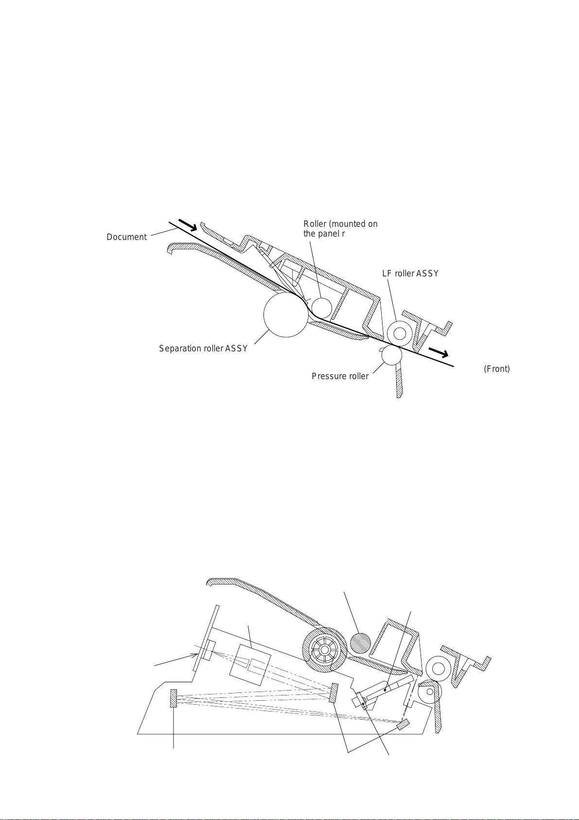
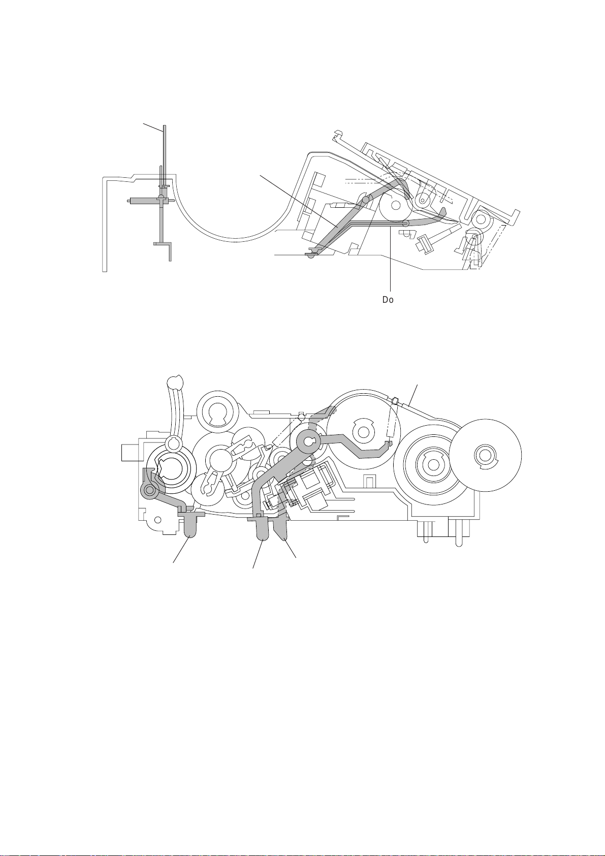
2.1 Transmitting Mechanism (Feeding and Scanning Documents)
The transmitting mechanism consists of the document stacker, automatic document feeder
(ADF), document feeding related rollers, scanner, and document sensors. (For details about
the sensors, refer to Section 2.3.)
If the operator sets documents on the stacker and starts the sending operation, the ADF
feeds those documents into the equipment, page by page. Each document advances with
the separation roller to the scanner, and then it is fed out of the equipment with the LF roller.
For the drive power source, refer to Section 2.4.
Roller (mounted on
Document
Separation roller ASSY
the panel rear cover)
LF roller ASSY
2.1.1 Automatic document feeder (ADF)
The ADF, which consists of the separation roller and separator, feeds documents set on the
document stacker, starting from the bottom sheet to the top, page by page, due to the frictional difference among the separation roller, the documents, and the separator.
2.1.2 Scanner
The scanner uses a charge coupled device (CCD) image sensor.
As shown below, the LED array illuminates a document and the reflected light of the scanned
image data is transmitted via the mirrors into the lens which reduces the scanned data so as
to form the image on the CCD.
Lens
Pressure roller
Separation roller ASSY
(Front)
Bar lens
CCD PCB
Mirror
(Front)
Mirrors LED array
III – 2
Page 16
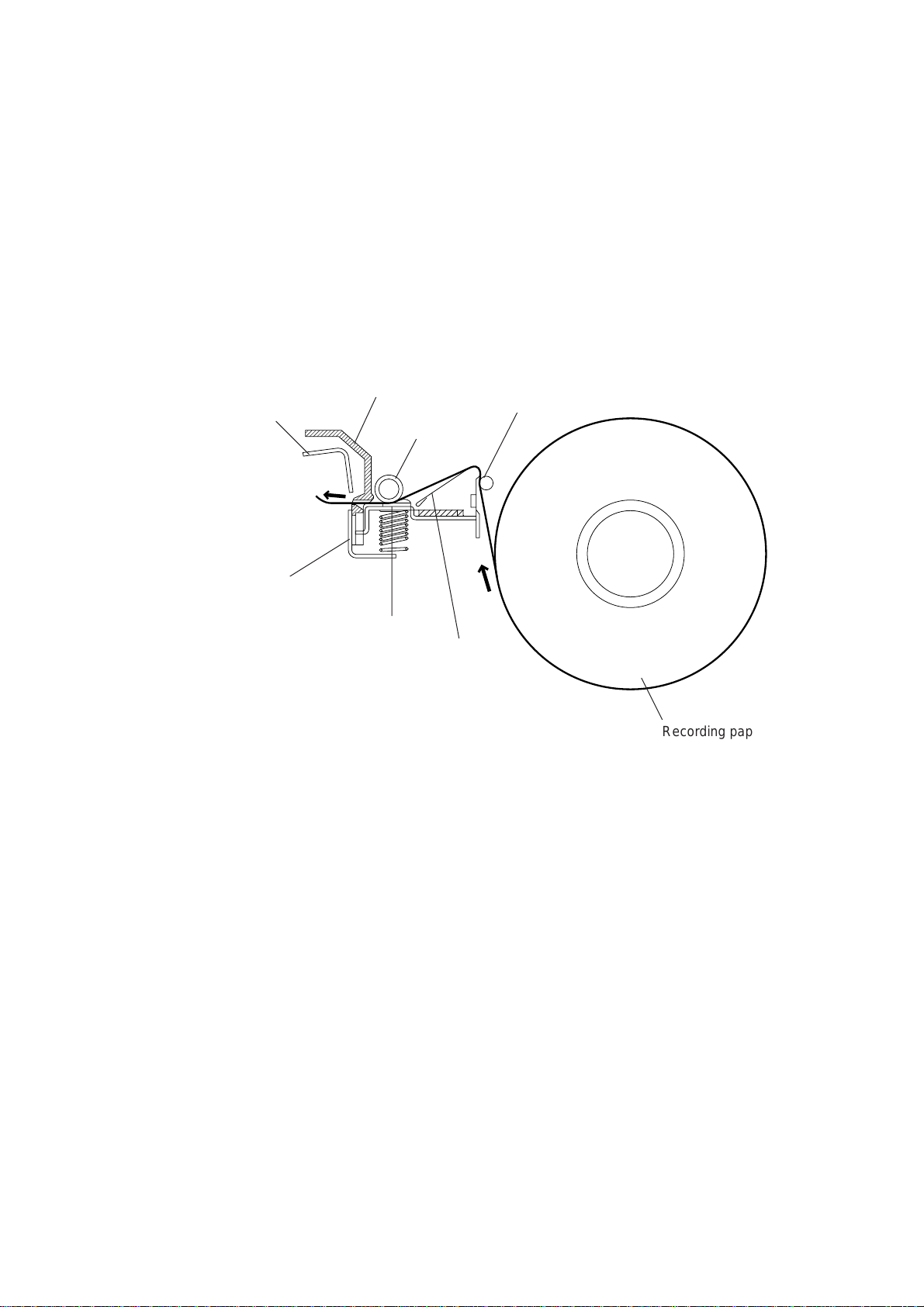
2.2 Receiving Mechanism (Feeding Recording Paper & Recording Data)
The receiving mechanism consists of the recording paper roll holder, anti-curl system (ACS),
platen, thermal recording head, automatic cutter, and sensors. (For details about the sensors, refer to Section 2.3.)
The recording paper is routed through the ACS to the recording head which prints onto the
heat-sensitive recording paper pressed by the platen according to received image signals.
The printed paper is further fed through the cutter chute and cut by the automatic cutter page
by page.
For the drive power source, refer to Section 2.4.
Upper blade
Lower blade
(Rear)
2.2.1 Anti-curl system (ACS)
The ACS eliminates curl peculiar to the rolled recording paper by curving the paper towards
the opposite side of the curl with the ACS rod and the ACS plate.
Cutter chute
Platen
Recording
head
ACS rod
ACS plate
Recording paper roll
2.2.2 Automatic cutter
The automatic paper cutter consists of an upper blade (rotary) and a lower blade (stationary). As the upper blade rotates around the left end as a support, the recording paper will be
cut. Upon completion of cutting operation, the upper blade returns to the home position
which is detected by the cutter sensor.
III – 3
Page 17
2.3 Sensors
This equipment has two photosensors and four mechanical sensors as described below.
Photosensors
• Document front sensor which detects a presence of documents.
• Document rear sensor which detects the leading and trailing edges of pages to tell the
control circuitry when the leading edge of a new page has reached the starting position
and when the scan for that page is over.
These two photosensors are located on the main PCB. They are of a reflection type consisting of a light-emitting diode and a light-receiving transistor. Each of them has an actuator
separately arranged (see the next page). If an actuator is activated, its white end will come
to the path of light issued from the light-emitting diode and reflect its light. The moment the
reflected light enters the light-receiving transistor, the sensor signals the detection.
Mechanical sensors
• PE (paper empty) sensor which detects whether the recording paper is present.
• Cover sensor which detects whether the recording paper cover is closed.
• Cutter sensor which detects the home position of the upper rotary blade of the automatic
cutter.
• Hook switch sensor which detects whether the handset is placed on the handset mount.
These four sensors are located on the NCU PCB. Each of them has an actuator separately
arranged (see the next page). If an actuator is activated, its lower end pushes down the lever provided on the corresponding sensor so that the sensor signals the detection.
(Rear)
NCU PCB
Cutter sensor
Hook switch
sensor
Cover sensor
SW3
SW4
SW2
PH1 PH2
Main PCB
SW1
PE sensor
Approx.
0.7 mm
Power supply PCB
Path of
actuator's end
Glass
Document rear sensor
Document front sensor
III – 4
Lightemitting
diode
Lightreceiving
transistor
Page 18
PE sensor
actuator
Document front
sensor actuator
(Front)
Document rear sensor actuator
Drive unit
Cutter sensor
actuator
(Front)
Cover sensor actuator
Hook switch
sensor actuator
Location of Sensor Actuators
III – 5
Page 19
2.4 Power Transmission Shift by the Planetary Gear Train and Clutch Solenoid
The equipment has a single drive motor whose power transmission route can be switched by
the planetary gear train and the clutch solenoid. Accordingly, the equipment mechanism can
function in four operation modes (recording, scanning, copying, and cutter driving modes).
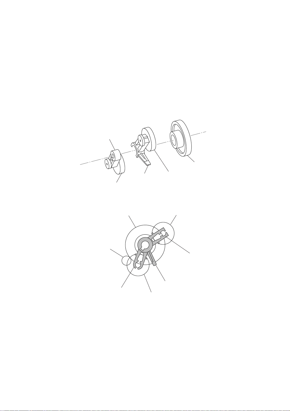
2.4.1 Description of planetary gear train
The planetary gear train consists of the sun gear 18/73, two planet gears 20, arm A, and arm
B, as shown below.
Arm B
Sun gear 18/73
Arm A
Planet gear 20B
Sun gear 18/73
Motor gear
Arm A
Planet gear 20A
Planet gear 20A
Planet gear 20B
Arm B
Stopper of arm A
If the motor rotates, the sun gear 18/73 rotates so that the rotational force is transmitted to
the engagement between the sun gear and the planet gears 20. Since the arms and planet
gears are so designed that the moment of the arms is less than that of the planet gears, the
arms turn around the center shaft in the same direction as the sun gear 18/73.
If the planet gear(s) becomes engaged with any other gear so that the arm cannot turn furthermore, the rotational force of the sun gear 18/73 is transmitted to that planet gear. Accordingly, the planet gear starts rotation in the opposite direction of the sun gear 18/73.
III – 6
Page 20
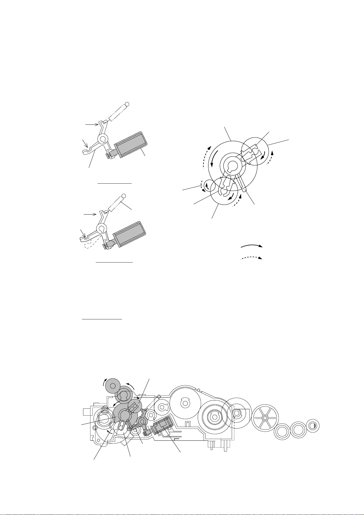
2.4.2 Power transmission for four operation modes
Depending upon the clutch solenoid ON/OFF state and the motor rotation direction, the planetary gear train switches the power transmission route for the four operation modes.
Section Y
Cutout X
Clutch lever
Section Y
Cutout X
(engaged
with stopper
of arm A)
[ 1 ] Recording mode (Solenoid: OFF, Motor rotation: Forward)
Solenoid: ON
Solenoid: OFF
Spring
Solenoid
Motor gear
Arm A
Sun gear 18/73
Arm B
Planet gear
20B
Stopper of arm A
Planet gear 20A
Forward
Reverse
In the recording mode, the control system deactivates the clutch solenoid (see the above figure, Solenoid: OFF). Therefore, when the motor rotates in the forward direction, the clutch
lever turns clockwise with the spring and its cutout X becomes engaged with the stopper of
arm A. Once arm A is locked, the planet gear 20A (C2) will not be engaged with any other
gear but simply idle.
The motor rotation turns the sun gear 18/73 (B) counterclockwise so that the planet gear 20B
(C1) transmits the rotation to the platen gear (E) via the gear D.
B (Sun gear
18/73)
E (Platen gear)
A (Motor gear)
C1 (Planet gear 20B)
D
F
Cutout X of
clutch lever
C2 (Planet
gear 20A)
(Front)
Clutch
solenoid
III – 7
Page 21
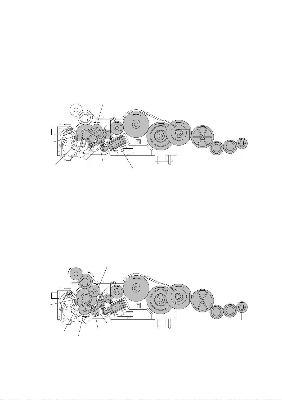
[ 2 ] Scanning mode (Solenoid: OFF, Motor rotation: Reverse)
Just as in the recording mode, the control system deactivates the clutch solenoid in the
scanning mode to lock arm A.
The motor rotates in the reverse direction and the sun gear 18/73 (B) rotates clockwise so
that the planet gear 20A (C2) transmits the rotation to the separation roller gear (L) and LF
roller gear (O) via the several gears.
C2 (Planet
gear 20A)
I
B (Sun gear
18/73)
A (Motor gear)
[ 3 ] Copying mode (Solenoid: ON ➞ OFF, Motor rotation: Forward)
F
Cutout X of
clutch lever
H
J
G
Clutch solenoid
K
L (Separation
roller gear)
M
(Front)
N
O (LF roller
gear)
The control system at first activates the clutch solenoid to release the stopper of arm A from
coutout X of the clutch lever while rotating the motor in the forward direction. Accordingly,
the sun gear 18/73 (B) rotates counterclockwise so that both the planet gears 20B (C1) and
20A (C2) transmit the rotation to the platen gear (E) and the roller gears (separation roller
gear and LF roller gear), respectively.
Once the planet gear 20A becomes engaged with the gear P, the control system deactivates
the clutch solenoid.
B (Sun gear
18/73)
A (Motor gear)
E (Platen gear)
C2 (Planet gear 20A)
C1 (Planet gear 20B)
D
H
G
F
P
Clutch lever
I
III – 8
K
J
L (Separation
roller gear)
M
(Front)
N
O (LF roller
gear)
Page 22

[ 4 ] Cutter driving mode (Solenoid: ON, Motor rotation: Reverse)
B (Sun gear
18/73)
Q (Cutter
gear)
The control system activates the clutch solenoid to release the stopper of arm A from cutout
X of the clutch lever. When the motor rotates in the reverse direction, the sun gear 18/73
(B) rotates clockwise so that the planet gear 20A (C2) transmits the rotation to the cutter
gear (Q).
Since the planet gear 20B (C1) is blocked by section Y of the clutch lever, it remains idling
without engaging with any other gear.
C1 (Planet gear 20B)
Section Y of clutch lever
(Front)
C2 (Planet gear 20A)
III – 9
Page 23

2.4.3 Power transmission route
Rotation of the motor gear is transmitted as shown below.
E
D
B
Q
A
C2
A: Motor gear
B: Sun gear 18/73
C1: Planet gear 20B
C2: Planet gear 20A
D: Gear 18/26
E: Platen gear
F: Gear 16A
G: Gear 16B
H: Gear 24
C1
H
G
F
P
I
J
K
L
O
M
N
I: Gear 44A
J: Gear 21/50
K: Gear 44B
L: Separation roller gear
M: Idle gear 24A
N: Idle gear 24B
O: LF roller gear
P: Gear 16C
Q: Cutter gear
[ 1 ] Recording Mode (Solenoid: OFF, Motor rotation: forward)
C1 ➔ D ➔ E
A ➔ B
C2 (idling)
[ 2 ] Scanning Mode (Solenoid: OFF, Motor rotation: reverse)
C1 (idling)
A ➔ B
C2 ➔ F ➔ G ➔ H ➔ I ➔ J ➔ K ➔ L ➔ M ➔ N ➔ O
[ 3 ] Copying Mode (Solenoid: ON ➔ OFF, Motor rotation: forward)
C1 ➔ D ➔ E
A ➔ B
C2 ➔ P ➔ F ➔ G ➔ H ➔ I ➔ J ➔ K ➔ L ➔ M ➔ N ➔ O
[ 4 ] Cutter Driving Mode (Solenoid: ON, Motor rotation: reverse)
C1 (idling)
A ➔ B
C2 ➔ Q
III – 10
Page 24
3. CONTROL ELECTRONICS
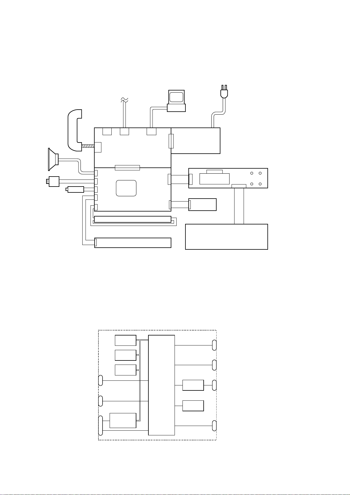
3.1 Configuration
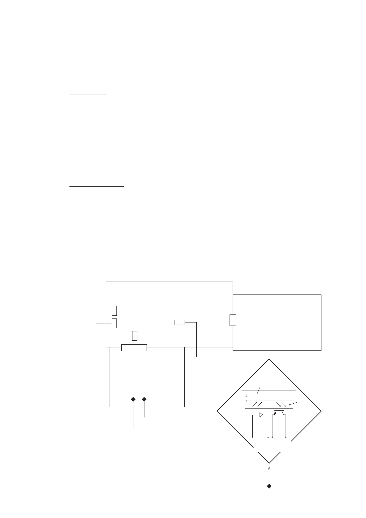
The hardware configuration of the facsimile equipment is shown below.
Speaker
Motor
Handset
Solenoid
Line
2-pin 8-pin
2-pin
4-pin
NCU PCB
(See NOTE
below.)
Main PCB
2-pin
6-pin
2-pin
12-pin
2-pin
26-pin
FAX
engine
LED array
Thermal recording head
NOTE: The FAX engine includes a CPU and gate array. In the FAX100/570/
615/625/635/675/575M/715M, it also includes a MODEM.
*1 On the NCU PCB are the
following switches:
PC
• PE sensor (SW1)
• Cover sensor (SW2)
• Cutter sensor (SW3)
• Hook switch sensor (SW4)
*
Power
8-pin
supply
PCB
*1
2 On the main PCB are the
following photosensors:
• Document front sensor
(PH1)
• Document rear sensor (PH2)
14-pin
5-pin
LCD
LEDs
*2
10-pin
CCD
PCB
13-pin
FPC key
3.2 Main PCB
The main PCB, which is the nucleus controlling the entire operation of the equipment, consists of a FAX engine (ASIC), memories, MODEM (except for FAX100/570/615/625/635/675/
575M/715M)
recording, and power transmission switching.
NCU and
Power supply
Speaker
LED array and
CCD PCB
Configuration of Facsimile Equipment
, motor drive circuitry, sensor detection circuitry, and analog circuits for scanning,
ROM
E2PROM
DRAM
Image
processor
FAX
engine
(ASIC)
Motor
driver
Sensors
Control panel
Recording head
Motor
PCI
E2PROM: Electrically Erasable Programmable Read-only Memory
DRAM: Dynamic Random Access Memory
Block Diagram of Main PCB
III – 11
Page 25
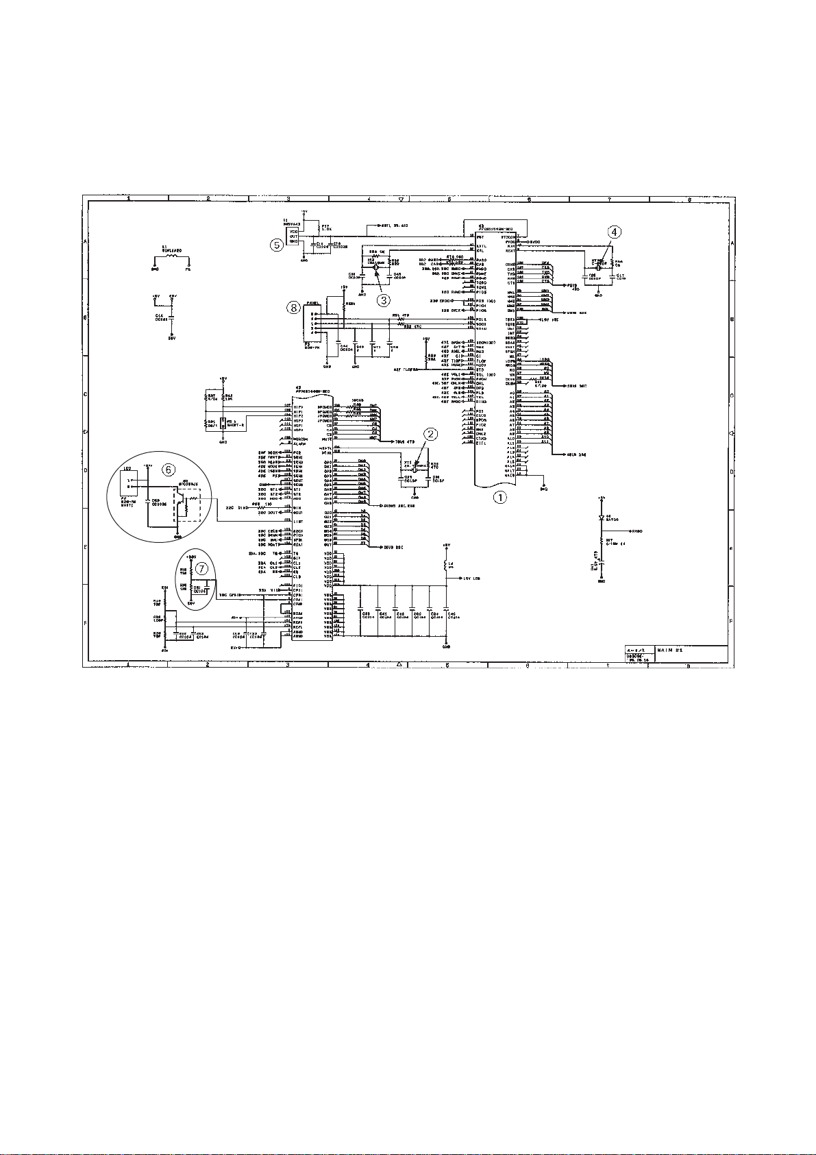
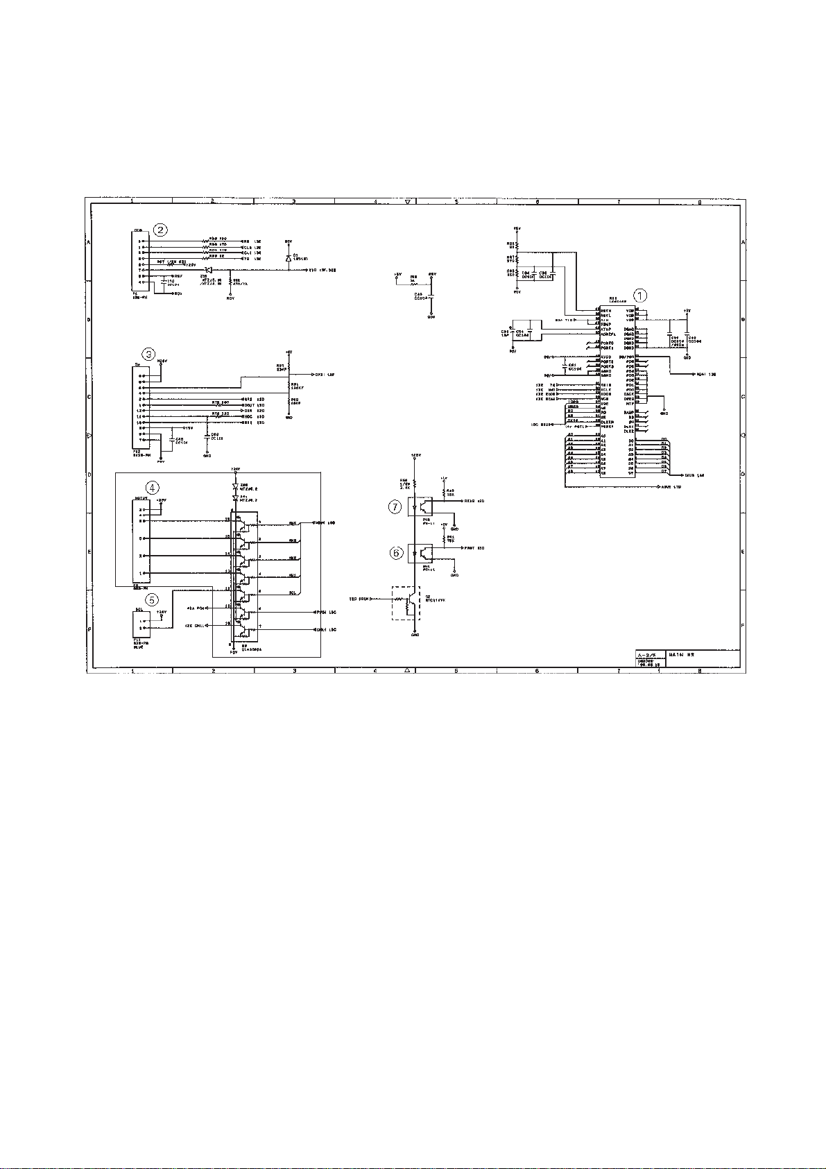
3.2.1 FAX100/570/615/625/635/675/575M/715M
[ 1 ] Primary function group
Main PCB Circuit Diagram 1/4
1 FAX engine (ASIC) which integrates a CPU, MODEM and gate array
2 Clock for MODEM
3 Clock for CPU
4 Clock for calendar clock
5 Reset IC
6 LED array light intensity control circuit and connector
7 Recording head drive voltage detector
8 Control panel connector
III – 12
Page 26
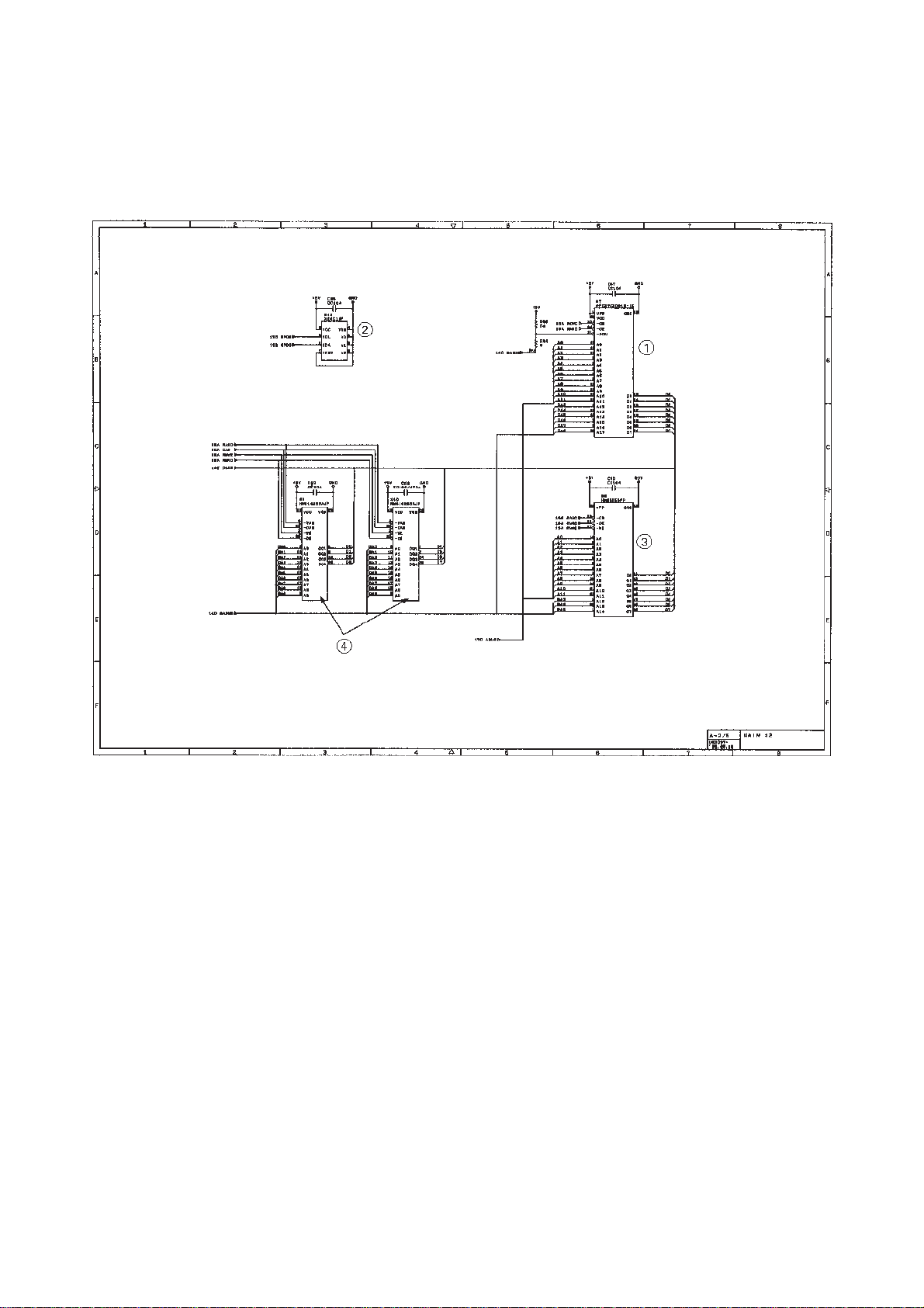
[ 2 ] ROM and DRAM group
Main PCB Circuit Diagram 2/4
1 ROM (2-megabit. Note that the sample machines for demonstration have a 4-
megabit ROM.)
2 E2PROM (16-kilobit)
3 DRAM (256-kilobit) for the FAX100/570/615/625/635/675
4 DRAMs (256-kilobit) for the FAX575M/715M
III – 13
Page 27
[ 3 ] Image processing group
Main PCB Circuit Diagram 3/4
1 Image processor (Image processing IC)
2 Connector for the CCD PCB
3 Recording head temperature detector and head connector
4 Motor driver and connector
5 Clutch solenoid connector
6 Document front sensor (photosensor)
7 Document rear sensor (photosensor)
III – 14
Page 28
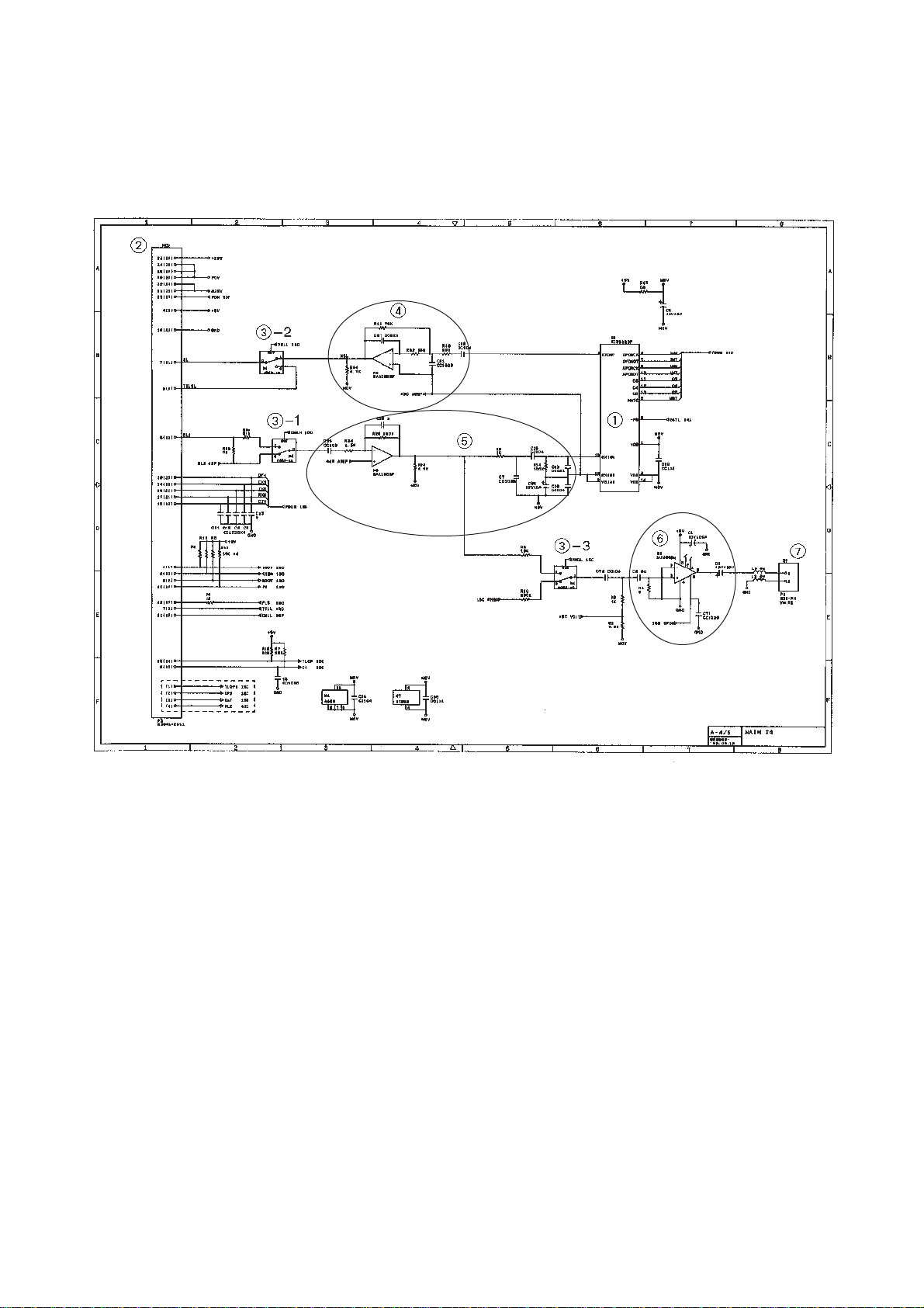
[ 4 ] Analog signal processing group
Main PCB Circuit Diagram 4/4
1 Analog front end IC
Processes the analog I/O signals from/to the MODEM.
2 Main-NCU connector
3 Analog signal selectors
3-1: Selects either RL1 or RL2 signals inputted from the communications net-
work.
3-2: Selects either input signals from the handset or those from the MODEM.
3-3: Selects either sound signals (e.g. alarm beeps, key clicks and ringer sounds)
generated by the FAX engine or signals selected by 3-1.
4 Amplifier circuit for signals outputted from the MODEM
5 Amplifier & shaper circuit for signals inputted from the communications network
6 Speaker amplifier circuit
Amplifies sounds issued from the above analog signal selector (3) and feeds them
to the speaker.
7 Speaker connector
III – 15
Page 29
3.2.2 FAX725M/590DT/590MC/825MC/875MC
[ 1 ] Primary function group
Main PCB Circuit Diagram 1/5
1 FAX engine (ASIC) which integrates a CPU and gate array.
2 Clock for CPU
3 Clock for calendar clock
4 ROM (2-megabit. Note that the sample machines for demonstration have a 4-
megabit ROM.)
5 E2PROM (16-kilobit in the FAX725M/590DT/590MC/825MC, 32-kilobit in the
FAX875MC)
6 Control panel connector
7 LED array light intensity control circuit and connector
8 Recording head drive voltage detector
III – 16
Page 30
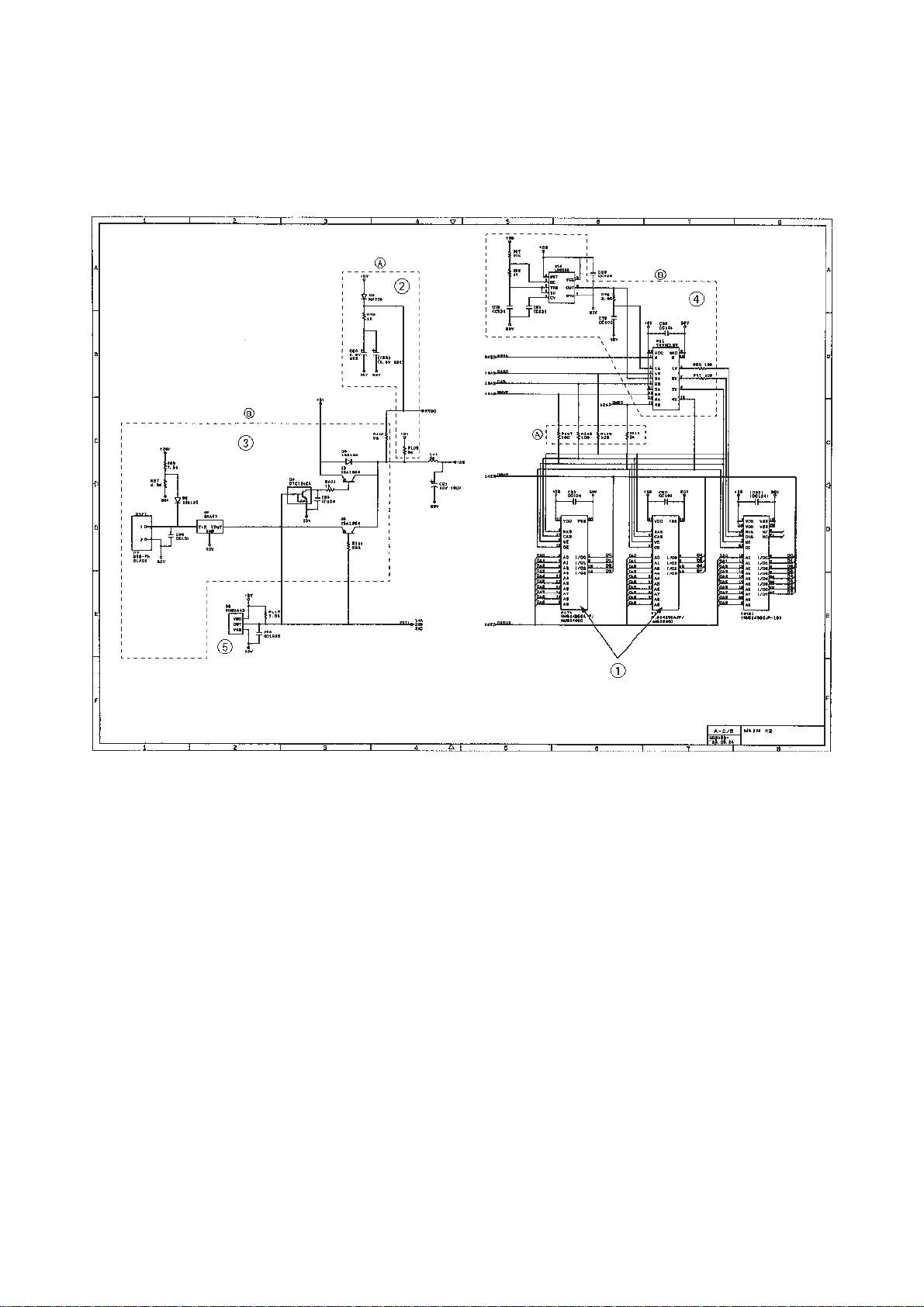
[ 2 ] DRAM group
Main PCB Circuit Diagram 2/5
1 DRAMs
FAX725M: Two 256-kilobyte DRAMs
FAX590DT/590MC/825MC/875MC: Two 512-kilobyte DRAMs
2 Calendar clock backup circuit (for the FAX725M)
3 DRAM backup circuit and nickel-hydrogen battery connector (for the FAX590DT/
590MC/825MC/875MC)
4 DRAM refresh circuit (for the FAX590DT/590MC/825MC/875MC)
5 Reset IC
III – 17
Page 31

[ 3 ] Image processing group
Main PCB Circuit Diagram 3/5
1 Image processor (Image processing IC)
2 Connector for the CCD PCB
3 Recording head temperature detector and head connector
4 Motor driver and connector
5 Clutch solenoid connector
6 Document front sensor (photosensor)
7 Document rear sensor (photosensor)
III – 18
Page 32

[ 4 ] Analog signal processing group
Main PCB Circuit Diagram 4/5
1 Main-NCU connector
2 Analog signal selectors
2-1: Selects either RL1 or RL2 signals inputted from the communications net-
work.
2-2: Selects either input signals from the handset or those from the MODEM.
2-3: Selects either sound signals (e.g. alarm beeps, key clicks and ringer sounds)
generated by the FAX engine or signals selected by 2-1.
3 Voice switching analog selectors
3-1: Selects either input signals from the communications network or those from
the MODEM, then feeds them to the speaker.
3-2: Selects either signals inputted from the communications network or recorded
voice signals inputted from the microphone or handset, then feeds them to
the MODEM.
4 Speaker output circuit and connector
5 Microphone connector and voice signal amplifier circuit
The voice signal amplifier circuit is applicable in those countries where telephones
can be used to call even during power failures.
III – 19
Page 33

[ 5 ] MODEM
1 MODEM
2 Clock for MODEM
Main PCB Circuit Diagram 5/5
III – 20
Page 34

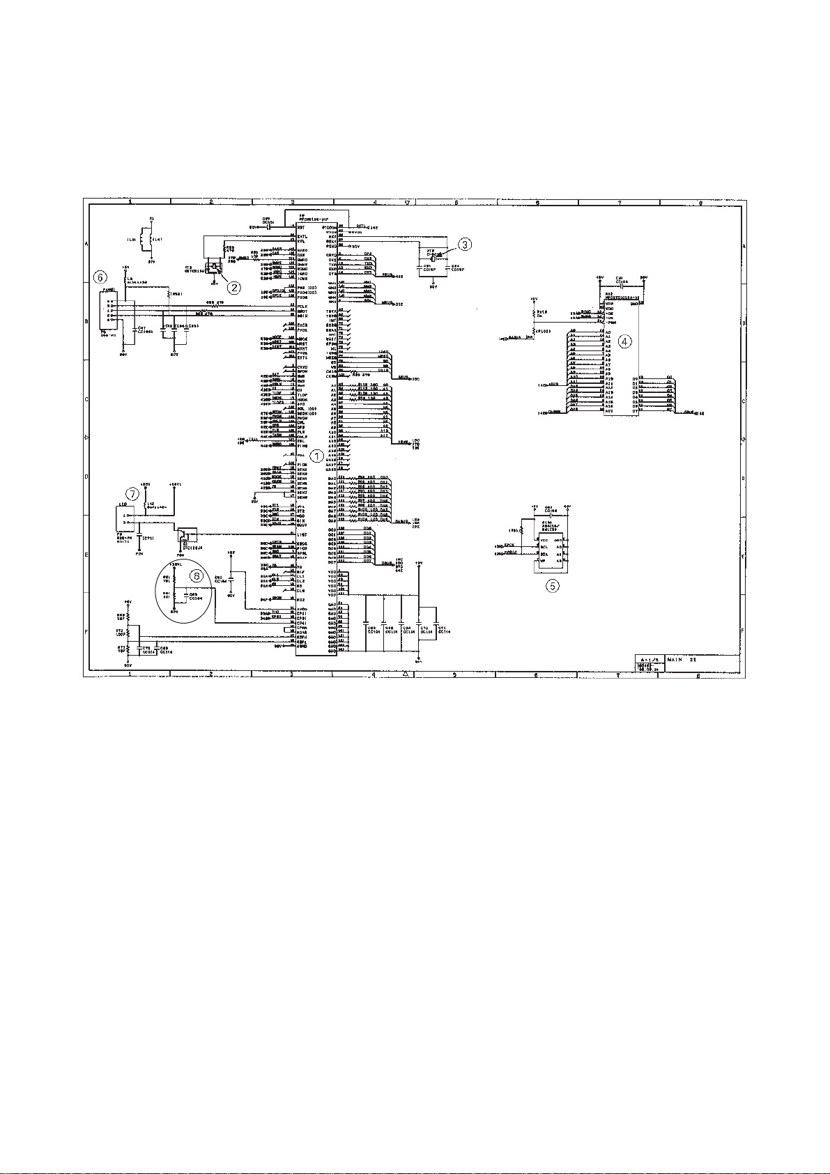
3.3 NCU PCB
The NCU PCB switches the communications line to telephone or built-in MODEM, under
control of the main PCB. Also, it works as a power supply interface from the power supply
unit to the main PCB and the recording head.
As shown in the circuit diagrams on the next page, the NCU PCB consists of the components listed below:
1 Surge absorber 7 Calling signal detector
2 Noise filter 8 Loop current detector
3 Line relay (CML relay) 9 Dial pulse generator
4 Line transformer : Telephone circuit
5 Circuit related to line transformer a Recording head interface
6 High-impedance transformer circuit
• The primary function of the NCU which is shared by facsimile and telephone units is to
switch a line to the facsimile unit or to the telephone, which is carried out by the line relay.
• Since the direct connection of a facsimile equipment to the line is not allowed for protecting the line, it is essential to insert a line transformer between the line and the facsimile
equipment to insulate them each other in direct current band.
The above two components, a line relay and a line transformer, are the minimum requirements for the NCU of the facsimile equipment.
• If an external telephone is attached to the facsimile equipment, the NCU should have a
loop current detector to identify the hook state by detecting loop current.
• If the facsimile equipment has an automatic answering facility, the NCU should be
equipped with a calling signal detector which detects a calling signal and tells it to the
CPU in the FAX engine.
• The circuit related to a line transformer allows the line transformer to be invariant by selecting the constants of the parts in this circuit so as to conform to the communications
regulations or codes of each country.
In addition to the above basic components of the NCU, the following components are also
required depending upon additional functions of the facsimile equipment:
• The dial pulse generator generates dial pulses within the facsimile equipment.
• The surge absorber is a protection circuit which absorbs lightning surge.
• The noise filter eliminates noise including radiation noise to prevent them from flowing out
onto the communications line.
• The high-impedance transformer circuit detects the remote activation, and F/T switching
sent from the line in ON-HOOK state without any interference to the line.
• The telephone circuit includes two amplifiers; one for amplifying the output signals of the
handset microphone and the other for amplifying the receive signals from the communications lines to sound the handset receiver.
III – 21
Page 35

5
a
6
3
2
4
:
7
8
9
1
2
NCU Circuit Diagram
III – 22
Page 36

3.4 Control Panel PCB
The control panel PCB and the main PCB communicate with each other by serially transmitting commands and data.
The control panel unit consists of a gate array, an LCD, and LEDs, which are controlled according to commands issued from the FAX engine on the main PCB.
The calendar clock is backed up by the backup circuit on the main PCB.
The panel FPC is a flexible keyboard PCB which integrates the key matrix having rubber
keytops.
FAX
Engine
RESET
Backup
Circuit
Main PCB
SIDN
SDOUT
PCLK
+5V
Reset
Circuit
Control Panel PCB
+5V
Control Panel PCB and its Related Circuit
Serial
Communications
Ports
Gate Array
I/O Ports
POWER
RESET
LCD
Panel FPC
(Key Matrix)
LED
S
III – 23
Page 37

3.5 Power Supply
The power supply uses the switching regulation system to generate the required DC power
(+5V and +26.6V) from the commercial AC power supply.
The 26.6V power source is fed to the NCU PCB where the +26.6VH source is generated.
The 26.6VH power source, which drives the recording head, outputs 26.6 VDC only when
the 26.6V ON/OFF control signal sent from the main PCB turns High.
The 26.6V power source mainly drives the motor for feeding documents and recording pa-
per.
Signals other than +26.6VH are connected to the main PCB through the NCU PCB and
+26.6VH is fed to the recording head.
Commercial
AC Power Line
Fuse
Lightning
Surge
Absorption
Circuit
Oscillator
Circuit
Link
Filter
Output Feedback
Power Supply Circuit
Rectifier
Circuit
26.6 V
Output
Circuit
5 V
Output
Circuit
NCU PCB
26.6 VH
Output
Circuit
26.6 V ON/OFF
Control Signal
26.6 VH
26.6 V
5 V
III – 24
Page 38

CHAPTER IV.
INDICATION AND INFORMATION
PRINTOUT OF ERROR
Page 39

CONTENTS
1. INDICATION AND PRINTOUT OF ERROR................................................... IV-1
2. EQUIPMENT ERROR.................................................................................... IV-1
2.1Error Messages on the LCD................................................................... IV-1
2.2Error Codes Shown in the “MACHINE ERROR xx” message................ IV-2
3. COMMUNICATIONS ERROR........................................................................ IV-4
3.1Definition of Error Codes on the Communications List........................... IV-5
Page 40

1. INDICATION AND PRINTOUT OF ERROR
To help the user or the service personnel promptly locate the cause of a problem (if any), the
facsimile equipment incorporates the self-diagnostic functions which display error messages
for equipment errors and communications errors.
For the communications errors, the equipment also prints out the transmission verification report and the communications list.
2. EQUIPMENT ERROR
If an equipment error occurs, the facsimile equipment emits an audible alarm (continuous beeping) for approximately 4 seconds and shows the error message on the LCD. For the error
messages, see Section 2.1. As one of the error messages, “MACHINE ERROR xx” includes
an error code which indicates the detailed error causes listed in Section 2.2. T o display an error
code for other latest error message, make the equipment enter the maintenance mode and
press 8 and 2 keys (for details, refer to Chapter V, Subsection 3.3.9).
2.1 Error Messages on the LCD
Messages on the LCD Probable Cause
PAPER ROLL EMPTY The paper empty (PE) sensor detects that no recording paper
is present.
PRINTER JAM The recording paper failed to return to the printing position after
it had been cut.
COVER OPEN The cover sensor detects that the the recording paper cover is
not closed.
DOCUMENT JAM ■ Document jam
(1) The document length exceeds the limitation (400 or 90 cm)
registered by firmware switch WSW16. (Refer to Chapter
V , Subsection 3.3.5.)
(Both the document front and rear sensors stay ON after
the document has been fed by the registered length.)
(2) The document rear sensor detects no trailing edge of a
document after the document has been fed by 400 cm.
(The document rear sensor stays ON even after the
document has been fed when the document front and rear
sensors were OFF and ON, respectively.)
IV – 1
Page 41

Messages on the LCD Probable Cause
DOCUMENT JAM ■ Document loading error
(1) The document rear sensor detects no leading edge of a
document within 10 seconds from the start of document
loading operation.
(The document rear sensor stays OFF even after the
document has been fed when the document front sensor
was ON.)
(2) The loaded document is too short.
(Since the document is shorter than the distance between
the document front and rear sensors, the document front
sensor is turned OFF before the document rear sensor is
turned ON.)
CUTTER JAM The upper rotary blade of the automatic cutter failed to return to
the home position within the specified time after cutting the
recording paper.
CLEAN UP SCANNER In the scanning compensation data list printed by the mainte-
nance-mode function No. 05, less than fifty percent of the white
level data is faulty.
SCANNER ERROR In the scanning compensation data list printed by the mainte-
nance-mode function No. 05, fifty percent or more of the white
level data is faulty.
PRINTER FAULT
The thermistor in the recording head caused a heat error.
MACHINE ERROR xx “xx” indicates an error code. Refer to Section 2.2.
If only an alarm beep is heard without any message on the LCD when the equipment is powered up, the ROM or RAM will be defective.
2.2 Error Codes Shown in the “MACHINE ERROR xx” message
Error Code
xx
(Hex.)
82 Recording paper feeding error.
87 Fails to complete the sequence of recording operation.
( 89 Cutter jam. )
8A Wrong or weak contact of the recording head connectors.
( 8B Recording head overheat. )
( A1 Recording paper cover opened. )
( A2 Document too long to scan. )
( A3 Document not detected by the document rear sensor. )
Error factor
( A4 50% or more faulty of white level data. )
Error codes in parentheses do not appear in the “MACHINE ERROR xx”, since those errors are displayed as
messages described in Section 2.1. Those error codes appear in the communications error list if an equipment error occurs
during communications. Refer to Section 3.1, (13).
IV – 2
Page 42

Error Code
xx
Error factor
(Hex.)
A5 Faulty operation of DMA0 during scanning.
A6 Faulty operation of DMA1 during scanning.
A7 One-line feeding time-out error.
A8 One-line scanning time-out error.
A9 Abnormal scanning reference voltage.
AB Document feed-in amount measuring error.
AC Less than 50% faulty of white level data.
B1 CODEC LSI error.
( B8 Amplifier gain error. )
( B9 Light emission intensity error of the LED array. )
( BA Scanning error: The left-hand black reference line which is marked on
the document pressure bar for scanning width setting is not detected.)
( BB Scanning error: The right-hand black reference line which is marked on
the document pressure bar for scanning width setting is not detected.)
( BC Scanning error: Reduction miss)
( BD Scanning error: Enlargement miss)
D1 The MODEM setup bit sticks to High.
D2 CTS stays OFF or ON if the MODEM RTS is turned ON or OFF, re-
spectively.
D3 Bit B1A of the MODEM stays OFF.
D4 Bit RX of the MODEM stays OFF.
D5 The MODEM fails to complete the command transmission sequence.
D6 No MODEM interrupt for 60 seconds.
E1 Microprocessor (MPU) error on the control panel PCB.
( E4 Out of recording paper. )
( E5 Recording paper set error. )
E6 Write error in E2PROM.
E8 Data scanning error during transmission.
( EA Document removed at phase B.)
F3 Voice message recording or playing-back not started.
F5 EOL not found in page memory transmission mode.
FF Interface error of page memory command.
Error codes in parentheses do not appear in the “MACHINE ERROR xx”, since those errors are displayed as
messages described in Section 2.1. Those error codes appear in the communications list if an equipment
error occurs
during communications. Refer to Section 3.1, (13).
IV – 3
Page 43

3. COMMUNICATIONS ERROR
If a communications error occurs, the facsimile equipment
(1) emits an audible alarm (intermittent beeping) for approximately 4 seconds,
(2) displays the corresponding error message, and
(3) prints out the transmission verification report if the equipment is in sending operation.
Transmission Verification Report Sample
IV – 4
Page 44

3.1 Definition of Error Codes on the Communications List
(1) Calling
Code 1 Code 2 Causes
10 08 Wrong number called.
11 01 No dial tone detected before start of dialing.
11 02 Busy tone detected before dialing.
11 03 2nd dial tone not detected.
11 05 No loop current detected. *
11 06 Busy tone detected after dialing or called.
11 07 No response from the remote station in sending.
11 10 No tone detected after dialing.
17 07 No response from the remote station in receiving.
(2) Command reception
Code 1 Code 2 Causes
20 01 Unable to detect a flag field.
20 02 Carrier was OFF for 200 ms or longer.
20 03 Abort detected (“1” in succession for 7 bits or more).
20 04 Overrun detected.
20 05 A frame for 3 seconds or more received.
20 06 CRC error in answer back.
20 07 Undefined command received.
20 08 Invalid command received.
20 09 Command ignored once for document setting or for dump-
20 0A T5 time-out error
* Available in Germany and Austria only.
ing-out at turn-around transmission.
20 0B CRP received.
20 0C EOR and NULL received.
IV – 5
Page 45

(3) Compatibility [checking the NSF and DIS]
Code 1 Code 2 Causes
32 01 Remote terminal only with V.29 capability in 2400 or 4800
bps transmission.
32 02 Remote terminal not ready for polling
32 10 Remote terminal not equipped with password function or
its password switch OFF.
32 11 Remote terminal not equipped with or not ready for confi-
dential mail box function.
32 12 Remote terminal not equipped with or not ready for relay
broadcasting function.
32 13 No confidential mail in the remote terminal.
32 14 The available memory space of the remote terminal is less
than that required for reception of the confidential or relay
broadcasting instruction.
IV – 6
Page 46

(4) Instructions received from the remote terminal [checking the NSC, DTC, NSS, and DCS]
Code 1 Code 2 Causes
40 02 Illegal coding system requested.
40 03 Illegal recording width requested.
40 05 ECM requested although not allowed.
40 06 Polled while not ready.
40 07 No document to send when polled.
40 10 Nation code or manufacturer code not coincident.
40 11 Unregistered group code entered for relay broadcasting
function, or the specified number of broadcasting subscrib-
ers exceeding the limit.
40 12 Retrieval when not ready for retrieval.
40 13 Polled by any other manufacturers’ terminal while waiting
for secure polling.
40 17 Invalid resolution selected.
(5) Command reception [checking the NSF and DIS after transmission of NSS and DCS]
Code 1 Code 2 Causes
50 01 Vertical resolution capability changed after compensation
of background color.
IV – 7
Page 47

(6) ID checking
Code 1 Code 2 Causes
63 01 Password plus (lower 4 digits of telephone number) not
63 02 Password not coincident.
63 03 Polling ID coincident.
63 04 Entered confidential mail box ID uncoincident with the mail
63 05 Relay broadcasting ID not coincident.
63 06 Entered retrieval ID uncoincident with that of the mail box
(7) DCN reception
coincident.
box ID.
ID.
Code 1 Code 2 Causes
74 DCN received.
(8) TCF transmission/reception
Code 1 Code 2 Causes
80 01 Fallback impossible.
IV – 8
Page 48

(9) Signal isolation
Code 1 Code 2 Causes
90 01 Unable to detect video signals and commands within 6
90 02 Received PPS containing invalid page count or block
(10) Video signal reception
Code 1 Code 2 Causes
A0 03 Error correction sequence not terminated even at the final
A0 11 Receive buffer empty. (5-second time-out)
A0 12 Receive buffer full during operation except receiving into
seconds after CFR is transmitted.
count.
transmission speed for fallback.
memory.
A0 13 Decoding error continued on 500 lines.
A0 14 Decoding error continued for 10 seconds.
A0 15 Time-out: Five seconds or more for one-line transmission.
A0 16 RTC not found and carrier OFF signal detected for 6
A0 17 RTC found and command detected for 60 seconds.
A8 01 RTN, PIN, or ERR received at the calling terminal. *
A9 01 RTN, PIN, or ERR received at the called terminal. *
AA 18 Receive buffer full during receiving into memory.
(11) General communications-related
Code 1 Code 2 Causes
B0 01 Polarity inversion detected.
B0 02 Unable to receive the next-page data.
seconds.
* Available in Germany and Austria only.
B0 03 Unable to receive polling even during turn-around trans-
mission due to call reservation.
B0 04 PC interface error.
IV – 9
Page 49

(12) Maintenance mode
Code 1 Code 2 Causes
E0 01 Failed to detect 1300 Hz signal in burn-in operation.
E0 02 Failed to detect PB signals in burn-in operation.
E0 03 Failed to detect any command from the RS-232C interface
(13) Equipment error
Code 1 Code 2 Causes
FF xx Equipment error (For xx, refer to Section 2.2.)
in burn-in operation.
IV – 10
Page 50

CHAPTER V.
MAINTENANCE
Page 51

CONTENTS
1. DISASSEMBLY, REASSEMBLY, AND LUBRICATION................................. V-1
■Safety Precautions.................................................................................... V-1
■Preparation................................................................................................V-2
■How to Access the Object Component...................................................... V-2
■Disassembly Order Flow........................................................................... V-3
1.1 ROM Cover............................................................................................V-4
1.2 Recording Paper Cover........................................................................ V-4
1.3 Panel Cover ASSY................................................................................ V-5
1.4 Panel Rear Cover and Control Panel.................................................... V-6
1.5 Recorder & Cutter Unit.......................................................................... V-7
1.6 LF Roller ASSY......................................................................................V-9
1.7 Bottom Plate..........................................................................................V-10
1.8 Main PCB, NCU PCB, and Power Supply PCB.................................... V-11
1.9 Scanner Frame ASSY........................................................................... V-13
1.10Drive Unit...............................................................................................V-14
1.11Handset Mount and Speaker................................................................ V-15
■Lubrication.................................................................................................V-16
2. TROUBLESHOOTING................................................................................... V-17
2.1Introduction.............................................................................................V-17
2.2Precautions.............................................................................................V-17
2.3Checking prior to Troubleshooting......................................................... V-17
3. MAINTENANCE MODE................................................................................. V-23
3.1Entry into the Maintenance Mode.......................................................... V-23
3.2List of Maintenance-mode Functions..................................................... V-23
3.3Detailed Description of Maintenance-mode Functions........................... V-25
3.3.1E2PROM parameter initialization..................................................... V-25
3.3.2Printout of scanning compensation data......................................... V-26
3.3.3ADF performance test..................................................................... V-27
3.3.4Test pattern 1.................................................................................. V-27
Page 52

3.3.5Firmware switch setting and printout............................................... V-28
3.3.6Operational check of control panel PCB......................................... V-66
3.3.7Sensor operational check............................................................... V-69
3.3.8CCD scanner area setting............................................................... V-69
3.3.9Equipment error code indication..................................................... V-70
Page 53

1. DISASSEMBLY AND REASSEMBLY
■ Safety Precautions
To prevent the creation of secondary problems by mishandling, observe the following precautions during maintenance work.
(1) Always turn off the power before replacing parts or units. When having access to the
power supply, be sure to unplug the power cord from the power outlet.
(2) Be careful not to lose screws, washers, or other parts removed for parts replacement.
(3) When using soldering irons and other heat-generating tools, take care not to damage
the resin parts such as wires, PCBs, and covers.
(4) Before handling the PCBs, touch a metal portion of the equipment to discharge static
electricity, or the electronic parts may be damaged due to the electricity charged in your
body.
(5) When transporting PCBs, be sure to wrap them in conductive sheets such as aluminum
foil.
(6) Be sure to reinsert self-tapping screws correctly, if removed.
(7) Unless otherwise specified, tighten screws to the torque values listed below.
• Tapping screws
M2.6 : 3.5 kgf•cm
M3 x 8 : 5 kgf•cm
M3 x 10 : 7 kgf•cm
• Sems screws M3 : 7 kgf•cm
(Screws with washer)
• Stepped screws : 7 kgf•cm
(8) When connecting or disconnecting cable connectors, hold the connector bodies not the
cables. If the connector has a lock, always slide the connector lock to unlock it.
(9) After repairs, check not only the repaired portion but also that the connectors and other
related portions function properly before operation checks.
V – 1
Page 54

■ Preparation
Prior to proceeding to the disassembly procedure,
(1) Unplug the modular jack of the telephone line.
(2) Unplug modular jacks of external telephone sets if mounted.
(3) Unplug the modular jack of the curled cord and remove the handset. (See below.)
(4) Remove the recording paper roll, the document wire-extension, and the receive wire-
Document wire-extension
extension. (See below.)
Receive wire-extension
Recording paper roll
Curled cord
Handset
■ How to Access the Object Component
• On the next page is a disassembly order flow which helps you access the object compo-
nent. To remove the scanner frame ASSY, for example, first find it on the flow and learn
its number (9 in this case). You should remove parts numbered 6 through 8 so as to
access the scanner frame ASSY.
• Unless otherwise specified, the disassembled parts or components should be reas-
sembled in the reverse order of removal.
V – 2
Page 55

■ Disassembly Order Flow
Panel cover ASSY
3
Panel rear cover
- ADF parts
Control panel
- Control panel
PCB
- FPC key
4
Recorder &
cutter unit
5
ROM cover
1
Recording
paper cover
2
8
Bottom plate
7
8
8
NCU PCB**
Power supply
PCB
Main PCB*
9
LF roller ASSY
6
Scanner frame ASSY
- Separation roller ASSY
- Document front sensor
actuator
- Document rear sensor
actuator
PE sensor
actuator
Handset mount
Speaker
11
* On the main PCB are the following photoelectric sensors:
• Document front sensor (PH1)
• Document rear sensor (PH2)
** On the NCU PCB are the following mechanical switches:
• PE sensor (SW1)
• Cover sensor (SW2)
• Cutter sensor (SW3)
• Hook switch sensor (SW4)
10
Drive unit
- Motor
- Gears
- Cover sensor actuator
- Cutter sensor actuator
- Hook switch sensor
actuator
Main frame
V – 3
Page 56

1
2
1.1 ROM Cover
(1) Open the recording paper cover.
(2) Turn up the head release lever.
(3) Insert the tip of a flat screwdriver into slot “A” to release two pawls of the ROM cover
from the main frame.
(4) Lift up the ROM cover.
Flat screwdriver
Pawls
Slot “A”
Head release lever
Main frame
1.2 Recording Paper Cover
(1) Open the recording paper cover.
(2) As shown below, press section “B” with your thumb to release the recording paper
cover from the bosses provided on the main frame.
ROM cover
Recording paper cover
2
1
Recording paper
cover
Main frame
Boss
“B”
V – 4
Page 57

1.3 Panel Cover ASSY
(1) Disconnect the main-panel harness from the main PCB.
(2) Slightly open the panel cover ASSY.
(3) Push the right and left arms of the panel cover ASSY outwards with you thumbs as
shown below to unhook them from the bosses provided on the main frame, then open
the panel cover ASSY further.
Main PCB
Main-panel harness
Arm
1
Panel cover ASSY
2
3
Panel cover ASSY
Routing the harness
Main-panel harness
Main PCB
V – 5
Page 58

1.4 Panel Rear Cover and Control Panel
(1) Place the panel cover ASSY upside down.
(2) Remove the ADF parts from the panel rear cover.
(3) Remove the two screws.
(4) Insert the tip of a flat screwdriver into the slot between the panel rear cover and control
panel as shown below and unhook the panel rear cover from the 15 “x” pawls provided
on the control panel.
(5) To remove the control panel PCB, FPC key and LCD, unhook the PCB from the four “y”
pawls provided on the control panel.
14243
ADF parts
Panel rear cover
LCD
Control panel PCB
FPC key
4 “y” pawls
(Rear)
15 “x” pawls
Control panel
(Front)
■ Reassembling Notes
• When installing the panel rear cover to the control panel, first fit the rear edge into
place and then snap in the panel rear cover.
V – 6
Page 59

1.5 Recorder & Cutter Unit
(1) Disconnect the main-head harness from the main PCB.
(2) Remove the screw from the recorder & cutter unit.
(3) Release the lock of the cutter link and pull out the upper blade shaft from it.
(4) Pull up the recorder & cutter unit which is attached to the main frame with double-sided
adhesive tape, then remove it in the direction of the arrow shown below.
Lock
Main-head
harness
Ratchet
Upper blade shaft
Recorder & cutter unit
Cutter
link
Main PCB
■ Disassembly of recorder & cutter unit
1) Disconnect the main-head harness from the recorder PCB.
2) Remove the ratchet from the upper blade shaft, taking care not to deform it.
3) Slide the ACS plate upwards while pulling sections “a” towards you.
4) Unlock the two latches “b” of the cutter chute from the cutter chassis and pull up
the cutter chute.
Cutter chute (removed)
Latch “b”
"x"
ACS plate
Latch “b”
Cutter chute
(mounted)
“a”
Ratchet
Upper blade shaft
Slightly pull section “x” to the
left and turn the ratchet as
shown above.
Main-head harness
“a”
V – 7
Page 60

5) Turn down the left release lever.
6) Slide the left ACS catch towards you while pulling the lock “c” outwards.
In the same way, remove the right ACS catch.
ACS catch (R)
1
Release lever (L)
ACS catch (L)
2
3
“c”
7) Remove the right bushing from the platen ASSY while releasing the two pawls “d.”
Then, remove the platen ASSY.
8) Push down the recorder PCB and pull it towards you slightly to release the two tabs
“e” from the cutter chassis, taking care not to lose three springs.
9) Remove the right and left release levers from the release shaft.
Recorder PCB
Tab “e”
Tab “e”
Release lever (R)
Release shaft
Spring
Release lever (L)
Cutter chassis
Pawls “d”
Bushing (R)
V – 8
Platen ASSY
Page 61

■ Reassembly of recorder & cutter unit
• When installing the platen ASSY to the cutter chassis, orient the left bushing as
shown below. Then, fit the bushing into the cutter chassis from the left side while
pressing down the platen and the recorder PCB.
Platen
1.6 LF Roller ASSY
(1) Push down the lock arm on the scanner frame ASSY and pull out the LF roller ASSY in
the direction of the arrow shown below.
Platen ASSY
Bushing (L)
Cutter chassis
Right side view
Lock arm
1
Scanner frame
V – 9
2
LF roller ASSY
Page 62

1.7 Bottom Plate
(1) Place the machine upside down.
(2) Remove the five screws.
(3) Remove the bottom plate.
Inside of the bottom plate
Grounding terminal
Bottom plate
V – 10
Page 63

1.8 Main PCB, NCU PCB, and Power Supply PCB
(1) Disconnect the following seven harnesses from the main PCB as shown below:
• Main-head harness (12-pin)
• Main-panel harness (5-pin)
• CCD harness (10-pin)
• Speaker harness (2-pin)
• Motor harness (6-pin)
• Solenoid harness (2-pin)
• LED harness (2-pin)
FAX100/570/615/625/635/
675/575M/715M
Speaker
connector
CCD harness
Solenoid connector
Motor connector
Main-head connector
Main-panel
connector
CCD connector
LED connector
LED
harness
Mainpanel
harness
Solenoid
harness
Speaker
harness
Motor harness
Main-head harness
NCU PCB
FAX725M/590DT/590MC/
825MC/875MC
Speaker
connector
Main PCB
Main-panel connector
Nickel-hydrogen
battery connector
Power supply PCB
Main-head
connector
Solenoid
connector
Motor
connector
LED connector
CCD connector
V – 11
Page 64

(2) Take off the AC cord bushing from the main frame.
(3) Take out the main PCB, NCU PCB and power supply PCB.
AC cord
bushing
(4) Disconnect the main PCB and power supply PCB from the NCU PCB.
NCU PCB
SW1 (PE sensor)
Main PCB
SW3 (Cutter sensor)
SW4 (Hook switch sensor)
Grounding
plate
Power supply PCB
SW2 (Cover sensor)
PH2 (Document rear sensor)
PH1 (Document front sensor)
V – 12
Page 65

1.9 Scanner Frame ASSY
(1) Remove the two screws.
(2) Unhook the scanner frame ASSY from the two pawls provided on the main frame.
(3) Lift up the scanner frame ASSY.
NOTE: Never remove or replace the CCD PCB, CCD lens, mirrors, LED array or bar
lens.
Main frame placed
upside down
Scanner frame ASSY
Mirrors
CCD lens
Pawls
(4) To remove the separation roller ASSY, document front and rear sensor actuators, press
the a, b, and c locking pawls shown below with the tip of a flat screwdriver, respectively, and move the component to be removed to the left.
Separation roller
ASSY
CCD PCB
Document front
sensor actuator
b
a
c
Scanner frame
ASSY
LED array
Bar lens
V – 13
Document rear
sensor actuator
Page 66

NOTE: When accessing these components, take care not to scratch the mirrors, CCD
1.10 Drive Unit
(1) Remove the two screws.
(2) Lift up the drive unit.
(3) To remove the motor, press the lock and turn the motor in the direction of the arrow as
shown below.
lens, or bar lens.
Mirrors
Drive unit
Motor
Lock
Drive unit
Cutter sensor
actuator
Hook switch
sensor actuator
(Front)
Cover sensor actuator
V – 14
Page 67

1.11 Handset Mount and Speaker
(1) Insert the tip of a 0.5-mm-wide ruler into the slots between the handset mount and the
main frame and unhook the handset mount from the pawls provided on the main frame.
(2) Slightly lift up the handset mount slightly and take it off to the left.
Speaker
harness
Pawl
2
1
Speaker harness
3
Handset mount
(3) To remove the speaker or the hook switch, unhook the locks with a small-blade flat
screwdriver to disassemble the handset mount.
(4) Slide the speaker to the right.
Main PCB
Locks
Handset mount placed
upside down
1
Hook switch
Speaker
3
2
V – 15
Page 68

■ Lubrication
Apply two grains of grease (Molicoat EM-30) to each of the following lubrication points:
(1) LF roller ASSY and grounding plates
Grounding
plate
3
(2) Separation roller ASSY
LF roller ASSY
Scanner frame ASSY
V – 16
Separation roller ASSY
Page 69

2. TROUBLESHOOTING
2.1 Introduction
This chapter gives the service personnel some of the troubleshooting procedures to be followed if an error or malfunction occurs with the facsimile equipment. It is impossible to anticipate all of the possible troubles which may occur in future and determine the troubleshooting procedures, so this chapter covers some sample troubles. However, those samples will
help service personnel pinpoint and repair other defective elements if he/she analyzes and
examines them well.
Prior to proceeding to the troubleshooting, read CHAPTER IV, INDICATION AND INFORMATION PRINTOUT OF ERROR.
2.2 Precautions
Be sure to observe the following to prevent the secondary troubles from happening:
(1) Always unplug the AC power cord from the outlet when removing the covers and PCBs,
adjusting the mechanisms, or conducting continuity testing with a circuit tester.
(2) When disconnecting the connectors, do not pull the lead wires but hold the connector
housings.
(3) ● Before handling the PCBs, touch a metal portion of the machine to discharge static
electricity charged in your body.
● When repairing the PCBs, handle them with extra care.
● When removing the electronic devices with a soldering iron, do not leave solder chips
or lead wires inside the machine.
After repairing the defective section, be sure to check again if the repaired section works correctly. Also record the troubleshooting procedure so that it would be of use for future trouble
occurrence.
2.3 Checking prior to Troubleshooting
Prior to proceeding to the troubleshooting flowcharts, check that:
(1) Each voltage level on AC input lines and DC lines is correct.
(2) All cables and harnesses are firmly connected.
(3) None of the fuses are blown.
V – 17
Page 70

■ Control panel related
Trouble Action to be taken
(1) LCD shows nothing. • Check the main-panel harness between the main PCB and the
control panel.
• Check the interfaces between the main PCB, NCU PCB and
power supply PCB.
• Check the control panel PCB.
• Check the power supply PCB.
• Check the main PCB.
(2) Control panel
inoperative.
■ Telephone related
Trouble Action to be taken
(1) No phone call can be
made.
• Check the main-panel harness between the main PCB and the
control panel.
• Check the interfaces between the main PCB, NCU PCB, and
power supply PCB.
• Check the control panel PCB.
• Check the FPC key.
• Check the main PCB.
• Check the FPC key.
• Check the control panel PCB:
- Use the maintenance-mode function No. 13. (Refer to
Section 3.) If any defective keys are found, replace them.
• Check the NCU PCB.
• Check the main PCB.
(2) Speed dialing or one-
touch dialing will not
work.
• Check whether the ordinary dialing function (other than the
speed and one-touch dialing) works correctly or not.
- If yes, check the main PCB.
- If not, refer to item (1) above.
V – 18
Page 71

Trouble Action to be taken
(3) Speaker silent during
on-hook dialing.
(4) Dial does not switch
between tone and pulse.
(5) Telephone does not
ring.
■ Communications related
• Check whether the ordinary dialing function (other than the onhook dialing with the hook key) works correctly or not.
- If yes, proceed to the following checks:
- If not, refer to item (1) above.
• Check the speaker.
• Check the NCU PCB.
• Check the main PCB.
• Check the main PCB.
• Check the speaker.
• Check the NCU PCB.
• Check the main PCB.
Trouble Action to be taken
(1) No tone is transmitted. • Check the main PCB.
• Check the NCU PCB.
V – 19
Page 72

■ Image related
If the received or sent image has any trouble, first make a copy with the facsimile equipment.
If the copied image is normal, the remote terminal is defective. If it is abnormal, proceed to
the troubleshooting list given below:
Trouble
(1) All white images.
[At scanning side]
[At recording side]
(2) Image has white
vertical streaks.
[At scanning side]
Action to be taken
• Check the harnesses between the main PCB and CCD & lens
holder ASSY.
• Check the main PCB.
• Check the main-head harness between the main PCB and the
recording head.
• Check the NCU-head harness between the NCU PCB and the
recording head.
• Check that the compression springs beneath the recording head
are set in place.
• Check the main PCB.
• Check the recording head.
• Check the CCD & lens holder ASSY.
[At recording side]
(3) All black images.
[At scanning side] • Check the interfaces between the main PCB, NCU PCB, and
[At recording side]
(4) Image has black
vertical streaks.
[At scanning side]
[At recording side]
• Check the recording head.
CCD & lens holder ASSY.
• Check the LED harness.
• Check the LED array.
• Check the main PCB.
• Check the main PCB.
• Check the recording head.
• Check the CCD & lens holder ASSY.
• Check the recording head.
V – 20
Page 73

Trouble Action to be taken
(5) Faint/dark image.
[At scanning side] • Check the LED array.
• Check the main PCB.
[At recording side]
(6) Improper image align-
ment.
[In communications]
[At scanning side]
[At recording side]
(7) Stretched-out image or
compressed image.
[In communications]
• Check that the compression springs beneath the recording
head are set in place.
• Check the displayed error code. (Refer to Chap. IV.)
• Check the connection between the main PCB and the NCU
PCB.
• Check the interfaces between the main PCB, NCU PCB, and
CCD & lens holder ASSY.
• Check the main PCB.
• Check the main-head harness between the main PCB and the
recording head.
• Check the main PCB.
• Check the displayed error code. (Refer to Chap. IV.)
[At scanning side]
[At recording side]
• Check the separator and its related section.
• Check the document feed rollers and their related gears.
• Check the solenoid and the planetary gear train.
• Check the drive motor and its harness.
• Check that the compression springs beneath the recording
head are set in place.
• Check the platen and its gear.
• Check the solenoid and the planetary gear train.
• Check the drive motor and its harness.
V – 21
Page 74

■ Paper feeding related
Trouble Action to be taken
(1) Neither “COPY:
PRESS COPY” nor
“FAX: NO. & START”
message appears
although documents
are set.
(2) Document not fed. • Check the drive motor and its harness.
(3) Recording paper not
fed.
(4) The “CUTTER JAM”
message cannot be
removed.
• Check the document sensors according to the maintenancemode function No. 32. (Refer to Section 3.)
• Check the document feed rollers and their related gears.
• Check the main PCB.
• Check the solenoid and the planetary gear train.
• Check the drive motor and its harness.
• Check the ADF and its related section.
• Check the drive motor and its harness.
• Check the recording paper feed rollers and their related gears.
• Check the solenoid and the planetary gear train.
• Check the main PCB.
• Check the drive motor and its harness.
• Check the cutter sensor and its position.
• Check the cutter gear.
• Check the solenoid and the planetary gear train.
• Check the main PCB.
V – 22
Page 75

3. MAINTENANCE MODE
3.1 Entry into the Maintenance Mode
To make the facsimile equipment enter the maintenance mode, press the FUNCTION ,
* , 2 , 8 , 6 , and 4 keys in this order.
Within 2 seconds
The equipment beeps for approx. 3 seconds and displays "MAINTENANCE" on the LCD, in-
dicating that it is placed in the initial maintenance mode, a mode in which the equipment is
ready to accept entry from the keys.
To select one of the maintenance-mode functions listed in the table below, enter the corresponding 2-digit function code with the numerical keys on the control panel. (The details of
each maintenance-mode function are described in Section 3.3.)
NOTES: • Pressing the 9 key twice in the initial maintenance mode restores the equip-
ment to the standby state.
• Pressing the STOP button after entering only one digit restores the equipment to the initial maintenance mode.
• If an invalid function code is entered, the equipment resumes the initial maintenance mode.
3.2 List of Maintenance-mode Functions
Maintenance-mode Functions (1)
Function
Code
01 E2PROM Parameter Initialization 3.3.1
02
03
04
05
06
07
08
09
10
11
12
13
Printout of Scanning Compensation Data
ADF* Performance Test
Test Pattern 1
Firmware Switch Setting
Printout of Firmware Switch Data
Operational Check of Control Panel PCB
(Check of Keys and Buttons)
Function
Reference
Subsection
3.3.2
3.3.3
3.3.4
3.3.5
3.3.6
14
15
16
Operational Check of Control Panel PCB
(Check of LEDs)
* ADF: Automatic document feeder
(Continued on the next page.)
V – 23
3.3.6
Page 76

Maintenance-mode Functions (2)
Function
Code
32
55
82
91
Function
Sensor Operational Check
CCD Scanner Area Setting
Equipment Error Code Indication
E2PROM Parameter Initialization (except the telephone
number storage area)
Reference
Subsection
3.3.7
3.3.8
3.3.9
3.3.1
- - - - - - - - - - - - - - - - - - - - - - - - - - IMPORTANT - - - - - - - - - - - - - - - - - - - - - - - - - - - -
Basically, the maintenance-mode functions listed above should be accessed by service personnel only. However, you may allow end users to access some of these
ance of service personnel
(e.g. by telephone).
under the guid-
The user-accessible functions (codes 10, 11, 82, and 91) are shaded in the above table.
Function code 10 accesses the firmware switches WSW01 to WSW34, each of which has
eight selectors. You should not allow end users to access all of those selectors, but you may
allow them to access user-accessible selectors which are shaded in the firmware switch
tables in Subsection 3.3.5.
The service personnel should instruct end users to follow the procedure given below.
(1) Press the FUNCTION key and the MODE key in this order.
The LCD clears the current display.
NOTE: The MODE key is inoperable during standby for redialing, timer, paging, and
forwarding.
(2) Press the 0 key.
(3) Enter the desired function code (10, 11, 82, or 91) with the numerical keys.
For function code 10, access the desired firmware switch according to the operating
procedure described in Subsection 3.3.5.
V – 24
Page 77

FUNCTION key
FINE PHOTO S.FINE
PLAY
RESOLUTION
COVER PAGETEL-INDEX Q.SCAN
HOOK
HOLD
REDIAL/ PAUSE
SPEED DIAL
TAD FAX
ERASERECORD
FUNCTION HELP
ABC
1
GHI
4
PRS
7
DEF
2
3
JKL
MNO
5
6
TUV
WXY
8
9
QZ
0
01 02
11 12031304140515
06 07
16 17081809191020
SHIFT
SET CLEAR
0 key
(4) To make the equipment return to the standby state, press the STOP key.
- - - - - - - - - - - - - - - - - - - - - - - - - - - - - - - - - - - - - - - - - - - - - - - - - - - - - - - - - - - - - - - - -
3.3 Detailed Description of Maintenance-mode Functions
3.3.1 E2PROM parameter initialization
■ Function
The equipment initializes the parameters, user switches, and firmware switches registered in
the E2PROM, to the initial values. Entering the function code 01 initializes all of the E2PROM
areas, but entering 91 does not initialize some areas, as listed below.
AUTO F/T
MODE
S.VOLUME
LH
COPY
STOP
START
MODE key
STOP key
Data item
Maintenance-mode functions
User switches
Firmware switches
Remote activation code
Calendar clock
Activity report
Distinctive ringing patterns
registered (only for USA
version)
Page memory size
Station ID data
Cover page comments
Outside line number
Telephone function registration
One-touch dialing
Speed dialing
Group dialing
■ Operating Procedure
Function code
01
91
These will be
initialized.
All of these will
be initialized.
144444424444443
These will not
be initialized.
14444444444442444444444443
14444244443
(1) Press the 0 and 1 keys (or the 9 and 1 keys according to your need) in this
order in the initial maintenance mode.
The "PARAMETER INIT" will appear on the LCD.
(2) Upon completion of parameter initialization, the equipment returns to the initial mainte-
nance mode.
V – 25
Page 78

3.3.2 Printout of scanning compensation data
■ Function
The equipment prints out the white and black level data for scanning compensation.
■ Operating Procedure
Do not start this function merely after powering on the equipment but start it after carrying
out a sequence of scanning operation. Unless the equipment has carried out any scanning
operation, this function cannot print out correct scanning compensation data. This is because the equipment initializes white and black level data and takes in the scanning compensation reference data at the start of scanning operation.
(1) Press the 0 and 5 keys in this order in the initial maintenance mode.
The "WHITE LEVEL 1" will appear on the LCD.
(2) The equipment prints out the scanning compensation data list containing the following:
FAX100/570/615/625
a) 2-value quantized white level data (208 bytes)
b) 2-value quantized black level data (1 byte)
c) 2-value quantized LED light intensity value (1 byte)
Other models
a) 2-value quantized white level data (208 bytes)
b) 2-value quantized black level data (1 byte)
c) Photo-mode white level data (208 bytes)
d) Photo-mode black level data (1 byte)
e) LED light intensity value, 2-value quantized LED light intensity value, and photo-
mode LED light intensity
f) 2-value quantized A/D reference value and photo-mode AD reference value
(3) Upon completion of recording of the compensation data list, the equipment returns to
the initial maintenance mode.
NOTE: If a certain data is abnormal, that code will be printed in inline style.
Scanning Compensation Data List
V – 26
Page 79

3.3.3 ADF performance test
■ Function
The equipment counts the documents fed by the automatic document feeder (ADF) and displays the count on the LCD for checking the ADF performance.
■ Operating Procedure
(1) Set documents. (Allowable up to the ADF capacity.)
The "DOC. READY" will appear on the LCD.
(2) Press the 0 and 8 keys in this order.
The equipment
i) copies the 1st document and displays "P.01" on the LCD,
ii) feeds in and out the 2nd through 4th documents while counting without copying
them as the LCD shows the corresponding count,
iii) copies the 5th document and displays "P.05" on the LCD,
iv) feeds in and out the 6th through 9th documents while counting without copying
them as the LCD shows the corresponding count, and
v) copies the 10th document and displays "P.10" on the LCD.
(3) Upon completion of feeding in and out all of the documents, the final count appears on
the LCD.
(4) Press the STOP button to return the equipment to the initial maintenance mode.
3.3.4 Test pattern 1
■ Function
This function, much like the copying function, prints out test pattern 1 to allow the service
personnel to check for record data missing or print quality.
■ Operating Procedure
Press the 0 and 9 keys in this order in the initial maintenance mode.
The figure below shows test pattern 1.
Test Pattern 1
V – 27
Page 80

3.3.5 Firmware switch setting and printout
[ A ]Firmware switch setting
■ Function
The facsimile equipment incorporates the following firmware switch functions (WSW01
through WSW34) which may be activated with the procedures using the control panel keys
and buttons.
The firmware switches have been set at the factory in conformity to the communications
standards and codes of each country. Do not disturb them unless necessary. Some firmware switches may not be applicable in some versions. The firmware switch data list indicates "Not used." for those inapplicable switches.
Firmware Switches (WSW01 through WSW34)
WSW No. Function
WSW01 Dial pulse setting
WSW02 Tone signal setting
WSW03 PABX mode setting
WSW04 TRANSFER facility setting
WSW05 1st dial tone and busy tone detection
WSW06 PAUSE key setting and 2nd dial tone detection
WSW07 Dial tone setting 1
WSW08 Dial tone setting 2
WSW09 Protocol definition 1
WSW10 Protocol definition 2
WSW11 Busy tone setting
WSW12 Signal detection condition setting
WSW13 Modem setting
WSW14 AUTO ANS facility setting
WSW15 REDIAL facility setting
WSW16 Function setting 1
WSW17 Function setting 2
WSW18 Function setting 3
WSW19 Transmission speed setting
WSW20 Overseas communications mode setting
WSW21 TAD setting 1
WSW22 Copy resolution setting
WSW23 Communications setting
WSW24 TAD setting 2
WSW25 TAD setting 3
WSW26 Function setting 4
WSW27 Function setting 5
WSW28 Function setting 6
WSW29 Function setting 7
WSW30 Function setting 8
WSW31 Function setting 9
WSW32 Function setting 10
WSW33 Function setting 11
WSW34 Function setting 12
V – 28
Page 81

■ Operating Procedure
(1) Press the 1 and 0 keys in this order in the initial maintenance mode.
The equipment displays the "WSW00" on the LCD and becomes ready to accept a firmware switch number.
(2) Enter the desired number from the firmware switch numbers (01 through 34).
The following appears on the LCD:
(3) Use the ← and → keys to move the cursor to the selector position to be modified.
(4) Enter the desired number using the 0 or 1 key.
(5) Press the SET button. This operation saves the newly entered selector values onto
the E2PROM and readies the equipment for accepting a firmware switch number.
(6) Repeat steps (2) through (5) until the modification for the desired firmware switches is
completed.
(7) Press the SET or STOP button to return the equipment to the initial maintenance
mode.
NOTES: • To cancel this operation and return the equipment to the initial maintenance
mode during the above procedure, press the STOP button.
• If there is a pause of more than one minute after a single-digit number is entered for double-digit firmware switch numbers, the equipment will automatically return to the initial maintenance mode.
WSWxx 0 0 0 0 0 0 0 0
■ Note
The user-accessible selectors of the firmware switches are shaded in the tables given on the
following pages.
V – 29
Page 82

■ Detailed Description for the Firmware Switches
WSW01 (Dial pulse setting)
Selector
No.
Function
Setting and Specifications
No. 1 2
1
Dial pulse generation mode
2
00: N
0 1 : N+1
1 0 : 10-N
11: N
No. 3 4
3
4
Break time length in pulse
dialing
0 0 : 60 ms
0 1 : 67 ms (for 10 PPS)
1 0 : 40 ms (for 16 PPS)
1 1 : 64 ms
No. 5 6
5
Inter-digit pause
6
0 0 : 800 ms
0 1 : 850 ms
1 0 : 950 ms
1 1 : 600 ms
Switching between pulse (DP)
70:Yes1:No
and tone (PB) dialing, by the
function switch
8
Default dialing mode, pulse
(DP) or tone (PB) dialing
0: PB 1: DP
● Selectors 1 and 2: Dial pulse generation mode
These selectors set the number of pulses to be generated in pulse dialing.
N: Dialing "N" generates "N" pulses. (Dialing "0" generates 10 pulses.)
N + 1: Dialing "N" generates "N + 1" pulses.
10 - N: Dialing "N" generates "10 - N" pulses.
● Selectors 3 and 4: Break time length in pulse dialing
These selectors set the break time length in pulse dialing.
(Example: If "1", "2", and "3" are dialled when N is set by selectors 1 and 2.)
Break time length set by
selectors 3 and 4
"1" "2" "3"
● Selectors 5 and 6: Inter-digit pause
These selectors set the inter-digit pause in pulse dialing.
(Example: If "1", "2", and "3" are dialled when N is set by selectors 1 and 2.)
"1"
"2"
"3"
Inter-digit pause set by
selectors 5 and 6
V – 30
Page 83

● Selector 7: Switching between pulse (DP) and tone (PB) dialing, by the function switch
This selector determines whether or not the dialing mode may be switched between the
pulse (DP) and tone (PB) dialing by using the function switch.
● Selector 8: Default dialing mode, pulse (DP) or tone (PB) dialing
This selector sets the default dialing mode (pulse dialing or tone dialing) which may be
changed by the function switch. If the user switches it with the function switch when selector
7 is set to "0", the setting specified by this selector will be also switched automatically.
WSW02 (Tone signal setting)
Selector
No.
Function
Setting and Specifications
No. 1 2
1
2
Tone signal transmission time
length
0 0 : 70 ms
0 1 : 80 ms
1 0 : 90 ms
1 1 : 100 ms
No. 3 4
3
Min. pause in tone dialing
4
0 0 : 70 ms
0 1 : 80 ms
1 0 : 90 ms
1 1 : 140 ms
0: 0 dB 1: 8 dB
5
|
8
● Selectors 1 through 4: Tone signal transmission time length and Min. pause
Attenuator for the beep sound
level
0: 0 dB 1: 4 dB
0: 0 dB 1: 2 dB
0: 0 dB 1: 1 dB
These selectors set the tone signal transmission time length and minimum pause in tone dialing.
(Example: If "1", "2", "3", "4", and "5" are dialled.)
Tone signal transmission time
length set by selectors 1 and 2
"1"
● Selectors 5 through 8: Attenuator for the beep sound level
"2"
"3"
"4"
"5"
Min. pause set by
selectors 3 and 4
These selectors are used to adjust the sound level of beep generated as a ring backtone in
the F/T mode or as a signal during remote control operation or at the start of ICM recording.
Setting two or more selectors to "1" produces addition of attenuation assigned to each selector.
This setting will be limited if selector 8 of WSW23 is set to "0."
V – 31
Page 84

WSW03 (PABX* mode setting)
Selector
No.
1
2
3
4
5
6
7
Function
Not used.
Min. detection time length of
PABX dial tone, required for
starting dialing
Not used.
Dial tone detection in PABX
Setting and Specifications
No. 2 3 4
0 0 0 : 50 ms
0 0 1 : 210 ms
0 1 0 : 500 ms
0 1 1 : 800 ms
1 0 0 : 900 ms
1 0 1 : 1.5 sec.
1 1 0 : 2.0 sec.
1 1 1 : 2.5 sec.
No. 6 7
0 0 : No detection
(3.5 sec. WAIT)
0 1 : No detection
(5 sec. WAIT)
1 0 : No detection
(7 sec. WAIT)
1 1 : Detection
(Frequency only)
8
"R" key function
0: 1st dial tone 1: No 1st dial
detection add tone detection
* PABX: Private automatic branch exchange
NOTE: The WSW03 is not applicable in those countries where no PABX is supported, e.g.
U.S.A.
● Selectors 2 through 4: Min. detection time length of PABX dial tone, required for starting
dialing
Upon detection of the PABX dial tone for the time length set by these selectors, the equipment starts dialing.
These selectors are applicable only when both selectors 6 and 7 are set to "1" (Detection).
● Selectors 6 and 7: Dial tone detection in PABX
These selectors activate or deactivate the dial tone detection function which detects a dial
tone when a line is connected to the PABX.
Setting both of these selectors to "1" activates the dial tone detection function so that the
equipment starts dialing upon detection of a dial tone when a line is connected.
Other setting combinations deactivate the dial tone detection function so that the equipment
starts dialing after the specified WAIT (3.5, 5.0, or 7.0 sec.) without detection of a dial tone
when a line is connected.
V – 32
Page 85

● Selector 8: "R" key function
This selector determines whether or not the 1st dial tone detection function (specified by selectors 1 through 3 of WSW05) is added to the R key.
If this selector is set to "0", pressing the R key automatically activates the 1st dial tone detection function when the PABX and the automatic calling are selected by using the function
switch. If you press the R key and a dial number in succession, the equipment will automatically carry out the 1st dial tone detection function following the original transfer function as
shown below.
Original transfer
function of R key
1st dial tone detection function
WSW04 (TRANSFER facility setting)
Dial number
Selector
No.
Function
Setting and Specifications
1 Earth function in transfer facility 0: Provide 1: Not provide
2
3
4 0: OFF 1: High
Dual tone detection frequency
in ICM recording
Tone detection level in ICM
recording
No. 2 3
0 0 : 350 + 440 Hz (A)
0 1 : 440 + 480 Hz (B)
1 x : 480 + 620 Hz (C)
No. 5 6
5
Earth time length for earth
function
6
0 0 : 200 ms
0 1 : 300 ms
1 0 : 500 ms
1 1 : 700 ms
No. 7 8
7
8
Break time length for flash
function
0 0 : 80 ms
0 1 : 110 ms
1 0 : 250 ms
1 1 : 500 ms
NOTE: The WSW04 is not applicable in those countries where no transfer facility is supported,
e.g. U.S.A.
● Selector 1: Earth function in transfer facility
This selector determines whether or not the earth function is added to the transfer setting
menu to be accessed by the function switch.
● Selectors 5 and 6: Earth time length for earth function
These selectors set the short-circuiting time length of the telephone line (La or Lb) to ground.
This setting is effective only when the earth function is selected for the R key by using the
function switch.
● Selectors 7 and 8: Break time length for flash function
These selectors set the break time length.
This setting is effective only when the flash function is selected for the R key by using the
function switch.
V – 33
Page 86

WSW05 (1st dial tone and busy tone detection)
Selector
No.
Function
Setting and Specifications
No. 1 2 3
0 0 0 : 3.5 sec. WAIT
1
2
1st dial tone detection
0 0 1 : 7.0 sec. WAIT
0 1 0 : 10.5 sec. WAIT
0 1 1 : 14.0 sec. WAIT
1 0 0 : 17.5 sec. WAIT
3
1 0 1 : 21.0 sec. WAIT
1 1 0 : 24.5 sec. WAIT
111:
4 0: 2 seconds 1: 1 second
Max. pause time allowable for
remote ID code detection
Detection (Without WAIT)
No. 5 6
0 0 : No detection
5
6
Busy tone detection in automatic sending mode
0 1 : Detection only
after dialing
1 0 : No detection
1 1 : Detection before
and after dialing
Busy tone detection in automatic receiving mode
8
Not used.
0: Yes 1: No7
NOTE: Selectors 5 through 7 are not applicable in those countries where no busy tone detec-
tion is supported, e.g. U.S.A.
● Selectors 1 through 3: 1st dial tone detection
These selectors activate or deactivate the 1st dial tone detection function which detects the
1st dial tone issued from the PSTN when a line is connected to the PSTN.
Setting all of these selectors to "1" activates the dial tone detection function so that the
equipment starts dialing upon detection of a dial tone when a line is connected. (However, in
those countries which support no dial tone detection function, e.g. in the U.S.A., setting
these selectors to "1" makes the equipment start dialing after a WAIT of 3.5 seconds.) For
the detecting conditions of the 1st dial tone, refer to WSW07 and WSW08.
Other setting combinations deactivate the dial tone detection function so that the equipment
starts dialing after the specified WAIT (3.5, 7.0, 10.5, 14.0, 17.5, 21.0, or 24.5 seconds) without detection of a dial tone when a line is connected to the PSTN.
● Selector 4: Max. pause time allowable for remote ID code detection
This selector sets the maximum pause time allowable for detecting the second digit of a remote ID code after detection of the first digit in remote reception.
If selector 4 is set to "0" (2 seconds), for instance, a remote ID code whose second digit is
detected within 2 seconds after detection of the first digit only will become effective so that
the equipment will activate the remote function.
V – 34
Page 87

● Selectors 5 and 6: Busy tone detection in automatic sending mode
These selectors determine whether or not the equipment automatically disconnects a line
upon detection of a busy tone in automatic sending mode.
Setting selector 6 to "0" ignores a busy tone so that the equipment does not disconnect the
line.
Setting selectors 5 and 6 to "0" and "1", respectively, makes the equipment detect a busy
tone only after dialing and disconnect the line.
Setting both of selectors 5 and 6 to "1" makes the equipment detect a busy tone before and
after dialing and then disconnect the line.
● Selector 7: Busy tone detection in automatic receiving mode
This selector determines whether or not the equipment automatically disconnects a line upon
detection of a busy tone in automatic receiving mode
V – 35
Page 88

WSW06 (PAUSE key setting and 2nd dial tone detection)
Selector
No.
1
2
3
4
5
6
Function
PAUSE key setting and 2nd dial
tone detection
Detection of international tone
Setting and Specifications
No. 1 2 3
0 0 0 : No pause
0 0 1 : 3.5 sec. WAIT
0 1 0 : 7 sec. WAIT
0 1 1 : 10.5 sec. WAIT
1 0 0 : 14 sec. WAIT
1 0 1 : 17.5 sec. WAIT
1 1 0 : 2nd dial tone detection
only in pulse dialing
(DP) system
1 1 1 : 2nd dial tone detection
both in DP and pushbutton (PB) dialing
systems
No. 4 5 6
0 0 0 : 50 ms
0 0 1 : 210 ms
0 1 0 : 500 ms
0 1 1 : 800 ms
1 0 0 : 900 ms
1 0 1 : 1.5 sec.
1 1 0 : 2.0 sec.
1 1 1 : 2.5 sec.
7 No. of dial tone detection times 0: Once 1: Twice
8
● Selectors 1 through 3: PAUSE key setting and 2nd dial tone detection
2nd dial tone interrupt detecting
time
0: 30 ms 1: 50 ms
Selectors
123
0 0 0 No WAIT is inserted even if the PAUSE key is pressed.
001
010
011
100
101
110
111
Pressing the PAUSE key inserts WAIT in pulse dialing, as defined in
the above table.
If the PAUSE key is pressed repeatedly, the equipment beeps a refusal
sound and refuses the entry.
In hook-up dialing, however, the equipment allows repeated pressing
with an acceptance sound, but inserts WAIT only for the first pressing.
Each time the PAUSE key is pressed, the equipment detects a 2nd
dial tone.
If no 2nd dial tone is inputted within the specified time, the equipment
disconnects the line in automatic dialing, or it starts transmitting the
dial signal if given after depression of the PAUSE key in hook-up
dialing.
(In those countries where no dial tone detection function is supported,
setting these selectors to "1, 1, 0" or "1, 1, 1" inserts a WAIT of 3.5
seconds.)
V – 36
Page 89

● Selectors 4 through 6: Detection of international tone
Upon detection of the 2nd dial tone for the time length specified by these selectors, the
equipment starts dialing.
This setting is effective only when the 2nd dial tone detection function is activated by selectors 1 through 3 (Setting 1, 1, 0 or 1, 1, 1).
This function does not apply in those countries where no dial tone detection function is supported.
● Selector 7: No. of dial tone detection times
This selector sets the number of dial tone detection times required for starting dialing.
● Selector 8: 2nd dial tone interrupt detecting time
This selector sets the allowable time length of an interrupt which should not be interpreted as
an interrupt in the 2nd tone dialing.
V – 37
Page 90

WSW07 (Dial tone setting 1)
Selector
No.
Function
Setting and Specifications
No. 1 2
1
Frequency band range
2
0 0 : Narrows by 10 Hz
0 1 : Initial value
1 X : Widens by 10 Hz
3 Line current detection 0: No 1: Yes
No. 4 5 6
0 0 0 : -21 dBm
4
2nd dial tone detection level
5
(Z = 600 Ω)
6
0 0 1 : -24 dBm
0 1 0 : -27 dBm
0 1 1 : -30 dBm
1 0 0 : -33 dBm
1 0 1 : -36 dBm
1 1 0 : -39 dBm
1 1 1 : -42 dBm
7
1st dial tone interrupt detecting
time
0: 30 ms 1: 50 ms
8 Not used.
NOTE: Selectors 1, 2, and 4 through 7 are not applicable in those countries where no dial tone
is supported, e.g. U.S.A.
● Selectors 1 and 2: Frequency band range
These selectors set the frequency band for the 1st dial tone and the busy tone (before dialing) to be detected.
This setting is effective only when selectors 1 through 3 of WSW05 are set to "1, 1, 1."
● Selector 3: Line current detection
This selector determines whether or not the equipment should detect a line current before
starting dialing.
● Selectors 4 through 6: 2nd dial tone detection level
These selectors set the detection level of the 2nd dial tone.
● Selector 7: 1st dial tone interrupt detecting time
This selector sets the allowable time length of an interrupt which should not be interpreted as
an interrupt in the 1st dial tone dialing.
V – 38
Page 91

WSW08 (Dial tone setting 2)
Selector
No.
1
2
3
4
5
6
7
8
Function
1st dial tone detection time
length
Time-out length for 1st and 2nd
dial tone detection
Detection level of 1st dial tone
and busy tone before dialing
Setting and Specifications
No. 1 2 3
0 0 0 : 50 ms
0 0 1 : 210 ms
0 1 0 : 500 ms
0 1 1 : 800 ms
1 0 0 : 900 ms
1 0 1 : 1.5 sec.
1 1 0 : 2.0 sec.
1 1 1 : 2.5 sec.
No. 4 5
0 0 : 10 sec.
0 1 : 20 sec.
1 0 : 15 sec.
1 1 : 30 sec.
No. 6 7 8
0 0 0 : -21 dBm
0 0 1 : -24 dBm
0 1 0 : -27 dBm
0 1 1 : -30 dBm
1 0 0 : -33 dBm
1 0 1 : -36 dBm
1 1 0 : -39 dBm
1 1 1 : -42 dBm
● Selectors 1 through 3: 1st dial tone detection time length
Upon detection of the 1st dial tone for the time length set by these selectors, the equipment
starts dialing.
This setting is effective only when selectors 1 through 3 of WSW05 are set to "1, 1, 1."
● Selectors 4 and 5: Time-out length for 1st and 2nd dial tone detection
These selectors set the time-out length for the 1st and 2nd dial tone detection so that the
equipment waits dial tone input for the specified time length and disconnects itself from the
line when no dial tone is inputted.
V – 39
Page 92

WSW09 (Protocol definition 1)
Selector
No.
1 0: 256 octets : 64 octets
Frame length selection
Function
Setting and Specifications
2 Not used.
No. 3 4
3
|
No. of retries
4
0 0 : 4 times
0 1 : 3 times
1 0 : 2 times
1 1 : 1 time
5 T5 timer 0: 300 sec. 1: 60 sec.
6 T1 timer 0: 35 sec. 1: 40 sec.
7
control for no response from
the called station in automatic
Elapsed time for time-out
8
sending mode
No. 7 8
0 0 : 50 sec.
0 1 : 70 sec.
1 0 : 90 sec.
1 1 : 35 sec.
● Selector 1: Frame length selection
Usually a single frame consists of 256 octets (1 octet = 8 bits). For communications lines
with higher bit error rate, however, set selector 1 to "1" so that the facsimile equipment can
divide a message into 64-octet frames.
Remarks: The error correction mode (ECM) is a facsimile transmission manner in which
the equipment divides a message into frames for transmission so that if any data
error occurs on the transmission line, the equipment retransmits only those
frames containing the error data.
● Selectors 3 and 4: No. of retries
These selectors set the number of retries in each specified modem transmission speed.
● Selector 6: T1 time
This selector sets the time length for the T1 timer.
● Selectors 7 and 8: Elapsed time for time-out control
If the equipment receives no response (no G3 command) from the called terminal in automatic sending during the time set by these selectors, it disconnects the line.
V – 40
Page 93

WSW10 (Protocol definition 2)
Selector
No.
1
2
3
Switching of DPS, following the
CML ON/OFF
Time length from transmission
of the last dial digit to CML ON
Time length from CML ON to
CNG transmission
Function
Setting and Specifications
0: No 1: Yes
0: 100 ms 1: 50 ms
0: 2 sec. 1: 4 sec.
Time length from CML ON to
4 0: 0.5 sec. 1: 2 sec.
CED transmission (except for
facsimile-to-telephone switching)
No. 5 6
5
No. of training retries
6
0 0 : 1 time
0 1 : 2 times
1 0 : 3 times
1 1 : 4 times
7
8
● Selector 1: Switching of DPS, following the CML ON/OFF
Not used.
Not used.
Setting this selector to "1" switches DPS automatically following the CML ON/OFF operation.
This function is provided to conform to the Swedish standard.
● Selector 2: Time length from transmission of the last dial digit to CML ON
This selector sets the time length from when the equipment transmits the last dial digit until
the CML relay comes on.
● Selector 3: Time length from CML ON to CNG transmission
This selector sets the time length until the equipment transmits a CNG after it turns ON the
CML relay.
● Selector 4: Time length from CML ON to CED transmission
This selector sets the time length until the equipment transmits a CED after it turns ON the
CML relay. This setting does not apply to switching between facsimile and telephone.
● Selectors 5 and 6: No. of training retries
These selectors set the number of training retries to be repeated before automatic fallback.
V – 41
Page 94

WSW11 (Busy tone setting)
Selector
No.
Function
Setting and Specifications
No. 1 2
1
Frequency band range
2
0 0 : Narrows by 10 Hz
0 1 : Initial value
1 x : Widens by 10 Hz
3 Not used.
4
5
6
ON/OFF time length ranges
(More than one setting allowed)
7
8
1: 400-600/400-600 ms
1: 175-440/175-440 ms
1: 700-800/700-800 ms
1: 110-410/320-550 ms
1: 100-660/100-660 ms
NOTE: The WSW11 is not applicable in those countries where no busy tone detection is sup-
ported, e.g. U.S.A.
The setting of WSW11 is effective only when selectors 5 and 6 of WSW05 are set to "0,
1" or "1, 1" (Busy tone detection).
● Selectors 1 and 2: Frequency band range
These selectors set the frequency band for busy tone to be detected.
● Selectors 4 through 8: ON/OFF time length ranges
These selectors set the ON and OFF time length ranges for busy tone to be detected. If
more than one selector is set to "1", the ranges become wider. For example, if selectors 4
and 5 are set to "1", the ON and OFF time length ranges are from 175 to 600 ms.
V – 42
Page 95

WSW12 (Signal detection condition setting)
Selector
No.
1
2
3
4
5
6
7
8
Function
Min. OFF time length of calling
signal (Ci)
Max. OFF time length of calling
signal (Ci)
Detecting time setting
Delay
Not used.
Setting and Specifications
No. 1 2
0 0 : 300 ms
0 1 : 500 ms
1 0 : 700 ms
1 1 : 900 ms
No. 3 4
0 0 : 6 sec.
0 1 : 7 sec.
1 0 : 9 sec.
1 1 : 11 sec.
No. 5 6
0 0 : 800 ms (1000 ms*)
0 1 : 200 ms
1 0 : 250 ms
1 1 : 150 ms
0: Yes 1: No
* 1000 ms in Chinese or Hong Kong versions.
● Selectors 1 through 4: Min. and max. OFF time length of calling signal (Ci)
If the equipment detects the OFF state of calling signal (Ci) for the time length which is
above the value set by selectors 1 and 2 and less the value set by selectors 3 and 4, it interprets the Ci signal as OFF.
● Selectors 5 and 6: Detecting time setting
These selectors set the time length required to make the equipment acknowledge itself to be
called. That is, if the equipment continuously detects calling signals with the frequency set
by selectors 1 through 4 of WSW14 during the time length set by these selectors 5 and 6, it
acknowledges the call.
● Selector 7: Delay
Setting this selector to "0" allows the equipment to insert a 900 ms WAIT after
acknowledgement of the call until the equipment turns on the CML relay to start receiving
operation.
V – 43
Page 96

WSW13 (Modem setting)
Selector
No.
Function
Setting and Specifications
No. 1 2
1
Cable equalizer
2
00: 0 km
0 1 : 1.8 km
1 0 : 3.6 km
1 1 : 5.6 km
No. 3 4
3
Reception level (Z = 600 Ω)
4
0 0 : -43 dBm
0 1 : -47 dBm
1 0 : -49 dBm
1 1 : -51 dBm
0: 0 dB 1: 8 dB
5
|
Modem attenuator
8
0: 0 dB 1: 4 dB
0: 0 dB 1: 2 dB
0: 0 dB 1: 1 dB
The modem should be adjusted according to the user’s line conditions.
● Selectors 1 and 2: Cable equalizer
These selectors are used to improve the pass-band characteristics of analogue signals on a
line. (Attenuation in the high-band frequency is greater than in the low-band frequency.)
Set these selectors according to the distance from the telephone switchboard to the facsimile
equipment.
● Selectors 3 and 4: Reception level
These selectors set the optimum receive signal level.
● Selectors 5 through 8: Modem attenuator
These selectors are used to adjust the transmitting level of the modem when the reception
level at the remote station is improper due to line loss. This function applies for G3 protocol
signals.
Setting two or more selectors to "1" produces addition of attenuation assigned to each selector.
This setting will be limited if selector 8 of WSW23 is set to "0".
V – 44
Page 97

WSW14 (AUTO ANS facility setting)
Selector
No.
1
2
3
4
5
6
7
8
Function
Frequency band selection
(Lower limit)
Frequency band selection
(Upper limit)
No. of rings in AUTO ANS
mode
Setting and Specifications
No. 1 2
0 0 : 13 Hz
0 1 : 15 Hz
1 0 : 23 Hz
1 1 : 20 Hz
No. 3 4
0 0 : 30 Hz
0 1 : 55 Hz
1 0 : 70 Hz
1 1 : 70 Hz
No.5678
0000: Fixed to once
0001: Fixed to 2 times
0010: Fixed to 3 times
0011: Fixed to 4 times
0100: 1 to 2 times
0101: 1 to 3 times
0110: 1 to 4 times
0111: 1 to 5 times
1000: 2 to 3 times
1001: 2 to 4 times
1010: 2 to 5 times
1011: 2 to 6 times
1100: 1 to 10 times
1101: 2 to 10 times
1110: 3 to 5 times
1111: 4 to 10 times
● Selectors 1 through 4: Frequency band selection
These selectors are used to select the frequency band of calling signals for activating the
AUTO ANS facility.
● Selectors 5 through 8: No. of rings in AUTO ANS mode
These selectors set the number of rings to initiate the AUTO ANS facility.
V – 45
Page 98

WSW15 (REDIAL facility setting)
Selector
No.
Function
Setting and Specifications
No. 1 2
1
Selection of redial interval
2
0 0 : 5 minutes
0 1 : 1 minutes
1 0 : 2 minutes
1 1 : 3 minutes
3
No.3456
0000: 16 times
4
No. of redialings
5
0001: 1 time
0010: 2 times
0011: 3 times
| |
6
1111: 15 times
7
|
Not used.
8
● Selectors 1 through 6: Selection of redial interval and No. of redialings
The equipment redials by the number of times set by selectors 3 through 6 at intervals set by
selectors 1 and 2.
This setting is effective only when selector 7 is set to "0."
V – 46
Page 99

WSW16 (Function setting 1)
Selector
No.
1
2
Function
Automatic cutter 0: ON 1: OFF
CCITT superfine recommendation 0: OFF 1: ON
Setting and Specifications
0: Only from the 1: From all
3 Remote reception
connected telephones
external connected
telephone
4
|
Not used.
5
6 Exclusive line mode 0: OFF 1: ON
7
8
● Selector 1: Automatic cutter
Max. document length limitation
0: 400 cm 1: 90 cm
Communications list output 0: No 1: Yes
The selector activates or deactivates the automatic cutter.
● Selector 2: CCITT superfine recommendation
If this selector is set to "1", the equipment communicates in CCITT recommended superfine
mode (15.4 lines/mm). If it is set to "0", it communicates in native superfine mode.
● Selector 3: Remote reception
Setting this selector to "0" allows the facsimile equipment to receive data from the directly
connected external telephone only. Setting it to "1" allows the equipment to receive data
from all telephones connected in parallel as well as the directly connected external one.
If any of the following troubles occurs frequently, set this selector to "0".
• Dialing from any of the telephones connected in parallel to the outside line starts the facsimile equipment.
• Picking up any handset of the telephones connected in parallel while the facsimile equipment is in receiving operation disarranges the received image due to the superimposed
noise.
● Selector 6: Exclusive line mode
Setting this selector to "1" connects the equipment to the exclusive line, which enables transmission just by pressing the START button without dialing operation at both the calling and
called terminals.
● Selector 7: Max. document length limitation
This selector is used to select the maximum length of a document to be sent.
● Selector 8: Communications list output
Setting this selector to "1" prints a communications list for every transmission. This selector
should be set to "1" for error analysis only and set to "0" during ordinary use by the end user.
V – 47
Page 100

WSW17 (Function setting 2)
Selector
No.
Function
Setting and Specifications
No. 1 2
1
Off-hook alarm
2
0 0 : No alarm
0 1 : Always valid
1 X : Valid except when
‘call reservation’
is selected.
3
Power failure report output 0: ON 1: OFF
Clock/prompt alternate
indication on the LCD
0: OFF 1: ON4
5 Calendar clock type 0: USA type 1: European type
6
Error indication in activity report
0: NO 1: YES
7 Non-ring reception 0: OFF 1: ON
8 Not used.
● Selectors 1 and 2: Off-hook alarm
These selectors activate or deactivate the alarm function which sounds an alarm when the
communication is completed with the handset being off.
● Selector 3: Power failure report output
This selector determines whether or not the equipment outputs a power failure report when
the power is turned on.
● Selector 4: Clock/prompt alternate indication on the LCD
If this selector is set to "1", the calendar clock and the prompt "INSERT DOCUMENT" appear alternately on the LCD while the equipment is on standby; if it is set to "0", only the
calendar clock appears.
● Selector 5: Calendar clock type
If this selector is set to "0" (USA), the MM/DD/YY hh:mm format applies; if it is set to "1"
(European), the DD/MM/YY hh:mm format applies. Where, DD is the day, MM is the month,
YY is the last two digits of the year, hh is the hour, and mm is the minute.
● Selector 6: Error indication in activity report
This selector determines whether or not a communications error code will be printed in the
activity report.
● Selector 7: Non-ring reception
Setting this selector to "1" makes the equipment receive calls without ringer sound if the ring
delay is set to 0.
V – 48
 Loading...