

Brother FAX580MC, MFC660MC, FAX560 Service Manual

FACSIMILE EQUIPMENT
SERVICE MANUAL
MODEL: FAX560/FAX580MC/MFC660MC
FAX-T72/FAX-T74/FAX-T76

© Copyright Brother 2000
All rights reserved.
No part of this publication may be reproduced in any
form or by any means without permission in writing
from the publisher.
Specifications are subject to change without notice.

PREFACE
This publication is a Service Manual covering the specifications, construction, theory of operation,
and maintenance of the Brother facsimile equipment. It includes information required for field
troubleshooting and repair--disassembly, reassembly, and lubrication--so that service personnel will
be able to understand equipment function, to rapidly repair the equipment and order any necessary
spare parts.
To perform appropriate maintenance so that the facsimile equipment is always in best condition for
the customer, the service personnel must adequately understand and apply this manual.
This manual is made up of six chapters and appendices.
CHAPTER I. GENERAL DESCRIPTION
CHAPTER II. INSTALLATION
CHAPTER III. THEORY OF OPERATION
CHAPTER IV. DISASSEMBLY/REASSEMBLY AND LUBRICATION
CHAPTER V. MAINTENANCE MODE
CHAPTER VI. ERROR INDICATION AND TROUBLESHOOTING
Appendix 1. EEPROM Customizing Codes
Appendix 2. Circuit Diagrams
This manual describes the models and their versions to be destined for major countries. The specifications
and functions are subject to change depending upon each destination.

CHAPTER I.
GENERAL DESCRIPTION

CHAPTER I. GENERAL DESCRIPTION
CONTENTS
1. EQUIPMENT OUTLINE........................................................................................ I-1
1.1 External Appearance and Weight.................................................................. I-1
1.2 Components ................................................................................................. I-1
2. SPECIFICATIONS................................................................................................ I-2
1. EQUIPMENT OUTLINE
1.1 External Appearance and Weight
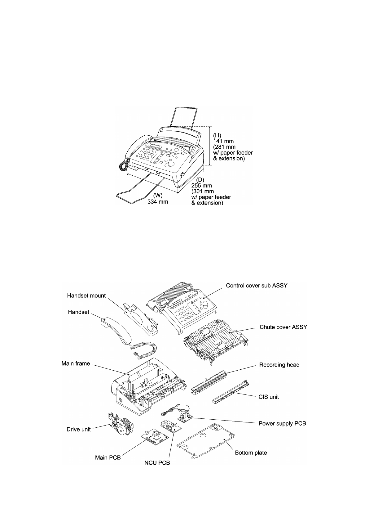
The figure below shows the equipment appearance and approximate dimensions.
Weight: Machine proper (excluding accessories) Approx. 2.9 kg
1.2 Components
The equipment consists of the following major components:
In package MFC660MC
Other models
Approx. 4.5 kg
Approx. 4.1 kg
I - 1

2. SPECIFICATIONS
Model Name FAX560 FAX580MC MFC660MC
Engine Thermal transfer Thermal transfer Thermal transfer
Color Upper: New Personal white
(1485)
Lower: 1473 gray
Transmission Speed (sec) 15 9 9
Modem Speed (bps) 9600 14,400 14,400
Group Compatibility G3 G3 G3
Input/Output Width 8.5"/8.5" 8.5"/8.5" 8.5"/8.5"
ADF (pages) 10 10 10
Paper Feeder (sheets) Letter: 50*, Legal: 30 Letter: 50*, Legal: 30 Letter: 50*, Legal: 30
Ribbon Yield (letter-size) 150 pages (47 m) 150 pages (47 m) 150 pages (47 m)
Starter Ribbon Yield (letter-size) 30 pages (10 m) 30 pages (10 m) 30 pages (10 m)
Replacement Roll PC401: 47 m (150 pages) PC401: 47 m (150 pages) PC401: 47m (150 pages)
LCD Size 16 x 1 16 x 1 16 x 1
On-Screen Programming Yes Yes Yes
Super Fine Yes Yes Yes
Smoothing Yes Yes Yes
Gray Scale (levels) 64 by Dithered 64 by Dithered 64 by Dithered
One Touch 4 4 4
Speed Dial 50 50 50
Telephone Index Yes as "Search" Yes as "Search" Yes as "Search"
Speaker Phone Monitor Full duplex (digital) Full duplex (digital)
Handset Yes Yes Yes
FAX/TEL Switch Yes Yes Yes
Distinctive Ring Detection Yes Yes Yes
Caller ID Yes Yes Yes
Call Waiting Caller ID Yes Yes Yes
TAD Interface Yes Yes Yes
Enhanced Remote Activation Yes Yes Yes
Automatic Redial Yes Yes Yes
Next-FAX Reservation Yes Yes Yes
Multi-Resolution Transmission Yes Yes Yes
Polling Type Sim/Seq Sim/Seq Sim/Seq
Delayed Transmission 3-timer 3-timer 3-timer
Call Reservation Yes Yes Yes
Electronic Coverpage Yes-Super Yes-Super Yes-Super
Call Back Message Yes Yes Yes
Activity Report Yes Yes Yes
TX Verification Report Yes Yes Yes
Memory Capacity (pages)
(up to 25 pages for OPR**)
ECM Yes Yes Yes
Broadcasting Yes Yes Yes
Quick Scan Yes Yes Yes
Out-of-Paper Reception Yes Yes Yes
512 KB
Upper: New Personal white
(1485)
Lower: 1473 gray
512 KB
(up to 25 pages for OPR**)
Upper: MFC white
(1495 gray)
Lower: 1473 gray
512 KB
(up to 25 pages for OPR**)
(1/2)
*Paper feeder: 50 sheets for US/Canada
**Page memory: 25 pages in OPR (out-of-paper reception), 22 pages in quick scan
I - 2

(1/2)
Model Name
FAX-T72
(Ger & Fra Only)
FAX-T74 FAX-T76
Engine Thermal transfer Thermal transfer Thermal transfer
Color New Personal black (1293) New Personal black (1293) New Personal black (1293)
Transmission Speed (sec) 15 15 9
Modem Speed (bps) 9600 9600 14,400
Group Compatibility G3 G3 G3
Input/Output Width 8.5"/8.5" 8.5"/8.5" 8.5"/8.5"
ADF (pages) 10 10 10
Paper Feeder (A4-size) 30 sheets 30 sheets 30 sheets
Ribbon Yield (A4-size) 130 pages (47 m) 130 pages (47 m) 130 pages (47 m)
Starter Ribbon (A4-size) Yes-10 m (30 pages) Yes-10 m (30 pages) Yes-10 m (30 pages )
Replacement Roll
LCD Size 16 x 1 16 x 1 16 x 1
On-Screen Programming Yes Yes Yes
Super Fine Yes Yes Yes
Smoothing Yes Yes Yes
Gray Scale (levels) 64 by Dithered 64 by Dithered 64 by Dithered
One Touch 4 4 4
Speed Dial 50 50 50
Telephone Index Yes as "Search" Yes as "Search" Yes as "Search"
Speaker Phone Monitor Monitor Full duplex (digital)
Handset No Yes Yes
FAX/TEL Switch Yes Yes Yes
Caller ID Yes
HOL/SWE/UK/IRE/ FRA/
NOR/BEL/ DEN/SPA
HOL/SWE/UK/IRE/ FRA/
NOR/BEL/ DEN/SPA
Yes
Yes
HOL/SWE/UK/IRE FRA/
NOR/BEL/ DEN/SPA
Call Waiting Caller ID No No No
Distinctive Ring Detection Yes for DEN/UK Yes for DEN/UK Yes for DEN/UK
TAD Interface Yes Yes Yes
Enhanced Remote Activation Yes Yes Yes
Automatic Redial Yes Yes Yes
Next-FAX Reservation Yes Yes Yes
Multi-Resolution Transmission Yes Yes Yes
Polling Type Sim/Sec/Del/Seq Sim/Sec/Del/Seq Sim/Sec/Del/Seq
Delayed Transmission 3-timer 3-timer 3-timer
Call Reservation Yes Yes Yes
Electronic Coverpage Yes-Super Yes-Super Yes-Super
Callback Message Yes Yes Yes
Journal Report Yes Yes Yes
TX Verification Report Yes Yes Yes
Memory Capacity
(up to 20 pages for OPR*)
512 KB
(up to 20 pages for OPR*)
512 KB
(up to 20 pages for OPR*)
512 KB
ECM Yes Yes Yes
Broadcasting Yes Yes Yes
Quick Scan Yes Yes Yes
*Page memory: 20 pages ITU-T No.1 chart in OPR (out-of-paper reception) in the ECM mode
I - 3

Model Name FAX560 FAX580MC MFC660MC
Multi-Copying w/ Sorting Yes Yes Yes
Enlargement/Reduction Ratio Yes (50-150%) Yes (50-150%) Yes (50-150%)
Multi-Transmission No No No
Confidential Mailbox No No No
Auto Reduction Yes Yes Yes
Message Center No Yes Yes
TAD Recording Time No 15 minutes 15 minutes
Fax Forwarding/Paging Yes Yes Yes
Fax Retrieval Yes Yes Yes
Fax-/Voice-on-Demand No No No
Fax & Voice Mailbox No No No
Help List Yes Yes Yes
Missing Link No Ready Included
Optional Memory No No No
Voice Alarm No No No
Output Tray Yes, wire included. Yes, wire included. Yes, wire included.
Others Call Manage Call Manage Call Manage
(2/2)
I - 4

Model Name
Out-of-Paper Reception Yes Yes Yes
Multi-Copying w/ Sorting Yes Yes Yes
Enlargement/Reduction Ratio Yes (50-150%) Yes (50-150%) Yes (50-150%)
Multi-Transmission No (w/o SHIFT key) No (w/o SHIFT key) No (w/o SHIFT key)
Confidential Mailbox No No No
Auto Reduction Yes Yes Yes
Message Manager No No Yes
TAD Recording Time No No 15 minutes
Fax Forwarding/Paging Yes-Only Fax Forwarding Yes-Only Fax Forwarding Yes-both
Fax Retrieval Yes Yes Yes
Fax-/Voice-on-Demand No No No
Fax & Voice Mailbox No No No
Help List Yes Yes Yes
MFL PRO for FAX No No Ready
Optional Memory No No No
Memo Manager No No No
Mute Key No Yes-music on hold;
Backup for Clock 9 hours 9 hours 15 hours
Output Tray Not available Not available Not available
Backup for Page Memory No No 6 hours
Power Consumption Standby: Less than 2 W
FAX-T72
(Ger & Fra Only)
Standby: Less than 2 W
Peak: 150 W
FAX-T74 FAX-T76
Yes-music on hold;
Green Sleeves
Peak: 150 W
Green Sleeves
Standby: Less than 2 W
Peak: 150 W
(2/2)
Remarks
Base models
w/o handset w/ handset
American models FAX560 FAX580MC/MFC660MC
European models FAX-T72 FAX-T74 FAX-T76
MC models
I - 5

CHAPTER II.
INSTALLATION

CHAPTER III.
THEORY OF OPERATION

CHAPTER III. THEORY OF OPERATION
CONTENTS
1. OVERVIEW........................................................................................................... III-1
2. MECHANISMS...................................................................................................... III-2
2.1 Scanning Mechanism.................................................................................... III-3
Automatic document feeder (ADF)................................................................ III-3
Scanner........................................................................................................ III-3
2.2 Printing Mechanism...................................................................................... III-3
Automatic cut sheet feeder (ACF) and registration mechanism..................... III-3
Printing and paper ejecting mechanism......................................................... III-3
2.3 Power Transmission Switching Mechanism ................................................... III-3
2.4 Sensors and Actuators.................................................................................. III-4
3. CONTROL ELECTRONICS.................................................................................. III-6
3.1 Configuration................................................................................................ III-6

1. OVERVIEW
III - 1
*Not provided on models w/o handset.
**Provided on MC models.
2. MECHANISMS
The facsimile equipment is classified into the following mechanisms:
n Scanning Mechanism - ADF mechanism
n Printing Mechanism - ACF and registration mechanism
n Power Transmission Switching Mechanism
n Sensors and Actuators
- Document scanning & feeding mechanism
- Printing and paper ejecting mechanism
III - 2

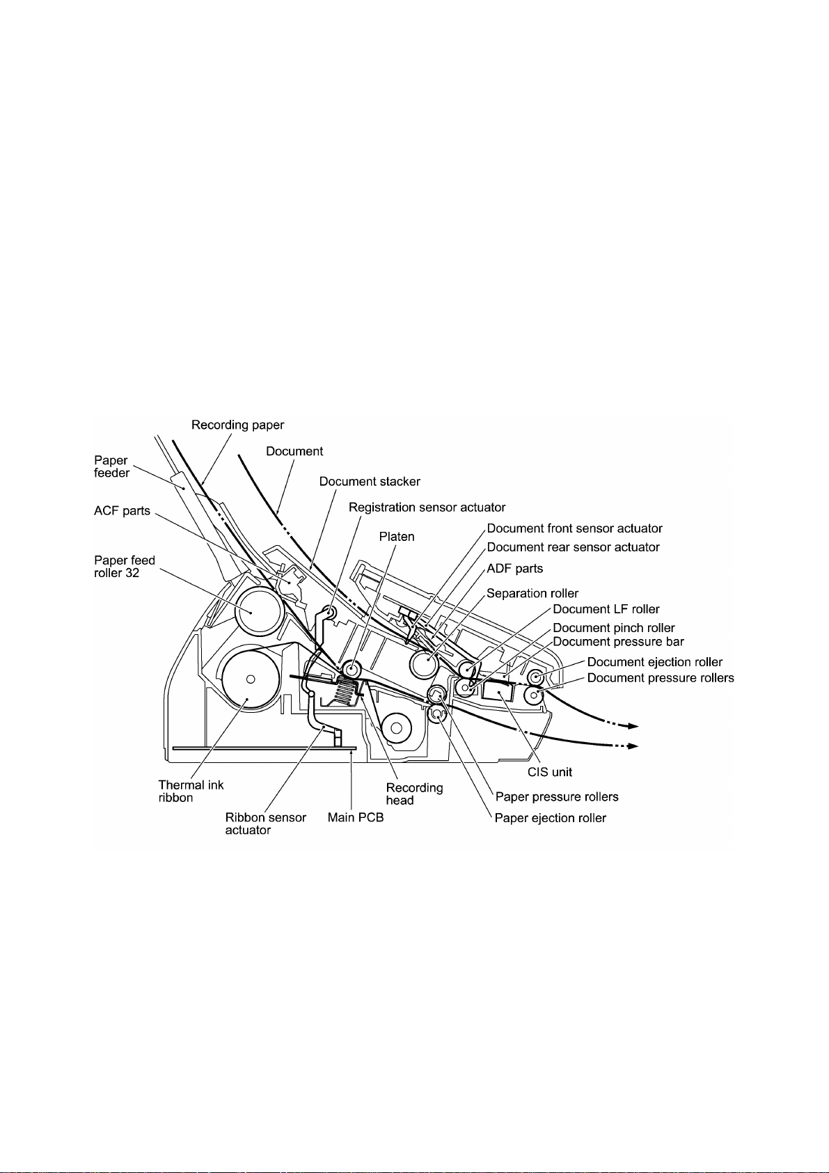
2.1 Scanning Mechanism
The scanning mechanism consists of the document stacker, automatic document feeder (ADF),
separation roller, document LF roller, scanner, document ejection roller, and document sensors.
(For details about the sensors, refer to Section 2.4.)
Automatic document feeder (ADF)
If the operator sets documents on the stacker and starts the transmitting operation, the ADF
(consisting of the separation roller and ADF parts) feeds those documents into the equipment,
starting from the bottom sheet to the top, page by page. Each document advances to the scanner
with the document LF roller, and then it is fed with the document ejection roller.
Scanner
The scanner uses a contact image sensor (CIS) unit which consists of an LED array illuminating
documents, a self-focus lens array collecting the reflected light, a CIS PCB carrying out
photoelectric conversion to output picture element data, and a cover glass on which a document
advances. When the document passes between the document pressure bar and the cover glass,
it is scanned.
2.2 Printing Mechanism
The printing mechanism consists of the paper feeder, automatic cut sheet feeder (ACF), paper
feed roller 32, platen, thermal recording head, paper ejection roller, and sensors. (For details
about the sensors, refer to Section 2.4.)
Automatic cut sheet feeder (ACF) and registration mechanism
If the operator sets cut sheets into the paper feeder and receiving operation starts, the ACF (paper
feed roller 32 and ACF parts) feeds paper into the equipment, a sheet at a time. After the leading
edge of paper passes through the registration sensor actuator, the paper is further fed for the
specified time length. Accordingly, the leading edge will reach the platen where the paper skew
will be eliminated.
Printing and paper ejecting mechanism
The platen feeds the paper up to the printing position where the thermal recording head prints
while the thermal ink ribbon advances. Then the paper is fed out of the equipment with the paper
ejection roller.
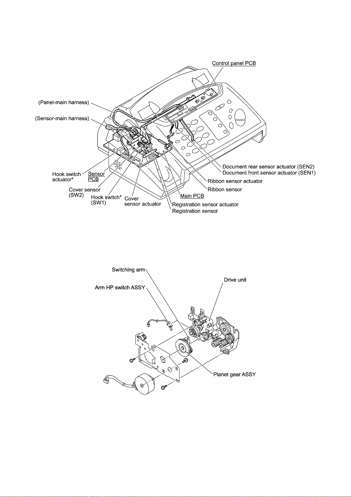
2.3 Power Transmission Switching Mechanism
The facsimile equipment has a single drive motor whose power transmission route can be
switched by the planetary gear system and by changing the motor rotation direction. This
switching allows the equipment to function in five operation modes—scanning, paper feeding,
recording, paper ejecting, and copying modes.
To switch to a particular mode, the motor rotates in the reverse direction. If the switching arm of
the planet gear ASSY turns on the arm HP switch, the motor further rotates by the specified
number of pulses to locate the planet gear ASSY in the particular mode position. Then the motor
rotates in the forward direction to enter the particular mode.
III - 3
2.4 Sensors and Actuators
This equipment has two photosensors and five mechanical switches as described below.
Sensor name Type Located on
Document front sensor Microswitch (SEN1) Control panel PCB
Document rear sensor Microswitch (SEN2) Control panel PCB
Cover sensor Microswitch (SW2) Sensor PCB
Hook switch* Microswitch (SW1) Sensor PCB
Registration sensor Photosensor Sensor PCB
Ribbon sensor Photosensor Main PCB
Arm HP switch Leaf switch Drive unit
• Document front sensor which detects the presence of documents.
• Document rear sensor which detects the leading and trailing edges of pages to tell the control
circuitry when the leading edge of a new page has reached the starting position and when the
scan for that page is over.
• Cover sensor which detects whether the control panel ASSY is closed.
• Hook switch sensor* which detects whether the handset is placed on the handset mount.
• Registration sensor which detects the leading and trailing edges of recording paper, which
allows the controller to determine the registration timing and check paper jam.
• Ribbon sensor which detects whether the ink ribbon is loaded.
• Arm HP switch which detects whether the switching arm of the drive unit is placed in the home
position.
*Not provided on models w/o handset.
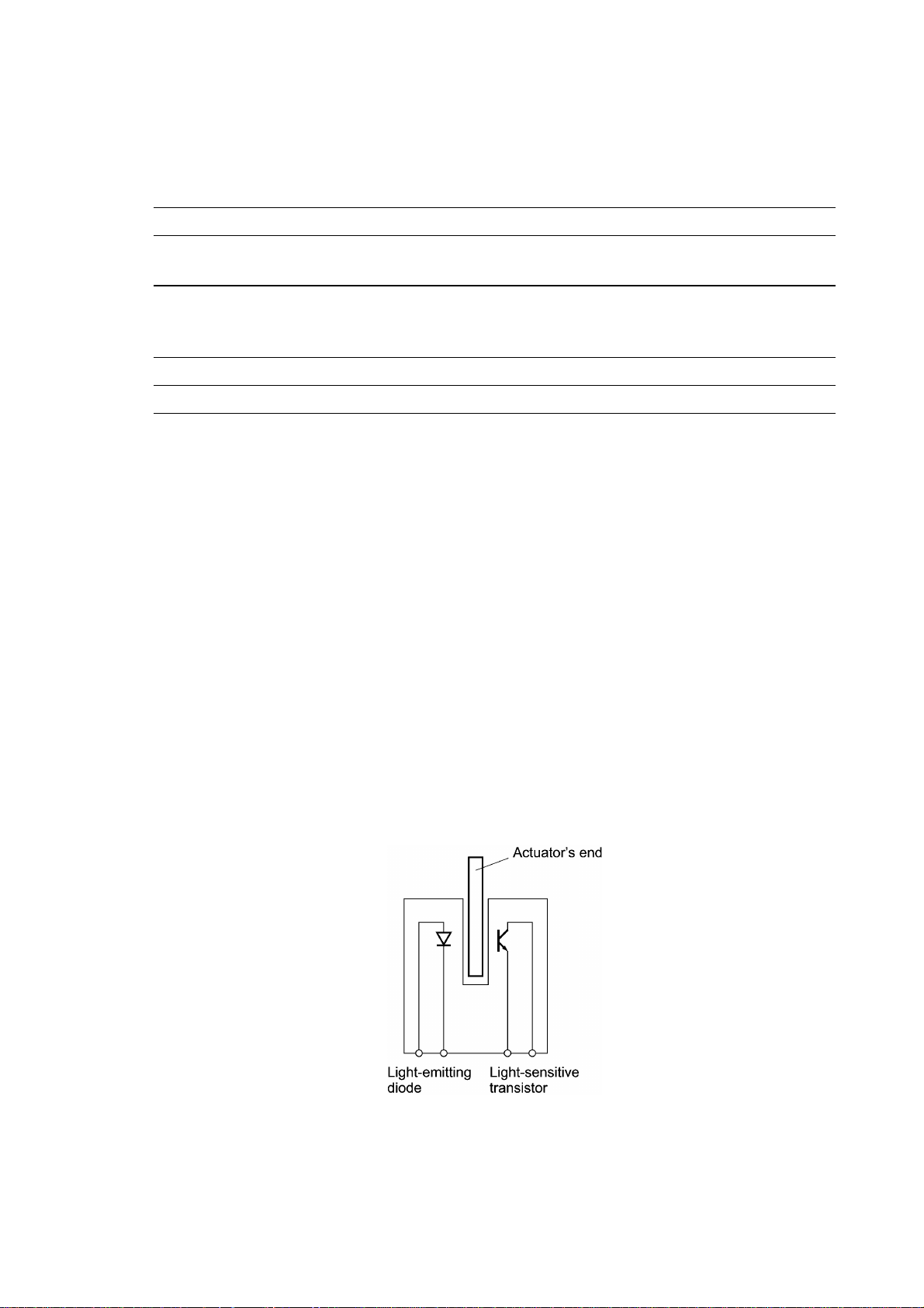
The registration sensor and ribbon sensor is a photointerrupter consisting of a light-emitting diode
and a light-sensitive transistor. Each of them has an actuator separately arranged (see the next
page). When an actuator is not activated, its black end lies in the path of light issued from the
light-emitting diode and interrupts its light so that the emitted light does not enter the light-sensitive
transistor. If paper or ribbon comes in so as to activate the actuator, the actuator's black end goes
out of the light path and the emitted light enters the light-sensitive transistor. This way, the sensor
detects the presence of paper or ink ribbon.
III - 4
*Not provided on models w/o handset.
Location of Sensors and Actuators
III - 5
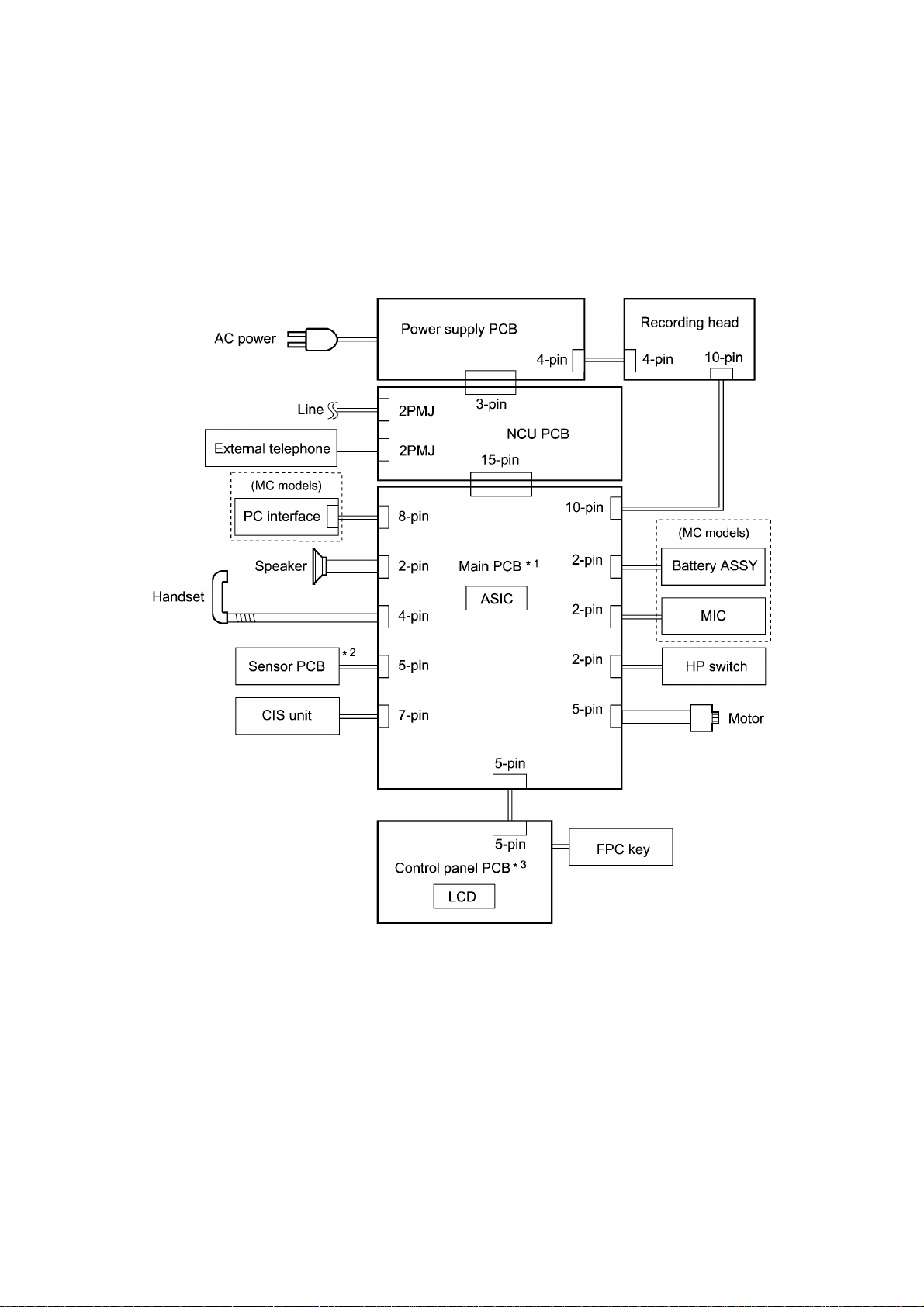
3. CONTROL ELECTRONICS
3.1 Configuration
The hardware configuration of the facsimile equipment is shown below.
*1 On the main PCB is the ribbon sensor.
*2 On the sensor PCB are these sensors:
l Cover sensor (SW2)
l Hook switch* (SW1)
l Registration sensor
*3 On the control panel PCB are these sensors:
l Document front sensor (SEN1)
l Document rear sensor (SEN2)
Configuration of Facsimile Equipment
III - 6

CHAPTER IV.
DISASSEMBLY/REASSEMBLY AND
LUBRICATION

CHAPTER IV. DISASSEMBLY/REASSEMBLY AND LUBRICATION
CONTENTS
1. DISASSEMBLY/REASSEMBLY........................................................................... IV-1
n Safety Precautions.............................................................................................. IV-1
Tightening Torque List........................................................................................ IV-2
n Preparation......................................................................................................... IV-3
n How to Access the Object Component................................................................ IV-3
n Disassembly Order Flow..................................................................................... IV-4
1.1 Cover Stopper Link, Ribbon Shaft Stopper, ROM Cover, and Control
Panel ASSY ................................................................................................... IV-5
1.2 Disassembly of the Control Panel ASSY (Document pressure bar and chute
cover ASSY) .................................................................................................. IV-7
1.3 Disassembly of the Chute Cover ASSY (Paper pressure rollers, separation
roller, paper feed roller 32, platen, registration sensor actuator, and lock
bar & lock levers) ........................................................................................... IV-10
1.4 Disassembly of the Control Cover Sub ASSY (ACF parts, ADF parts, panel
rear cover, control panel PCB, FPC key, LCD, and keys) ............................... IV-17
1.5 Handset Mount*1, Dummy Mount*2, Battery ASSY*3, Sensor PCB, Cover
Sensor Actuator, and Hook Switch Actuator*1................................................. IV-21
1.6 Paper Ejection Roller, Document LF Roller, and Document Ejection Roller.... IV-24
1.7 Head Protector, Recording Head ASSY, and Recorder Frame........................ IV-25
1.8 Drive Unit, Motor, and Arm HP Switch ASSY ................................................. IV-28
1.9 Speaker.......................................................................................................... IV-32
1.10 Lower Cover, Support Plate, and CIS Spring.................................................. IV-33
1.11 CIS Film and CIS Unit.................................................................................... IV-34
1.12 Document Pressure Rollers and Document Pinch Roller................................. IV-36
1.13 Bottom Plate, Main PCB, NCU PCB, Power Supply PCB, and Ribbon
Sensor Actuator.............................................................................................. IV-38
2. LUBRICATION...................................................................................................... IV-43
[ 1 ] Separation roller and its gear and paper feed roller 32 and its gear ......... IV-43
[ 2 ] Platen gear (Gear 24) and joint between gears 32 and chute cover
ASSY...................................................................................................... IV-44
[ 3 ] Paper ejection roller, document LF roller, and document ejection roller .. IV-45

1. DISASSEMBLY/REASSEMBLY
nn Safety Precautions
To prevent the creation of secondary problems by mishandling, observe the following precautions
during maintenance work.
(1) Unplug the power cord from the power outlet before replacing parts or units. When having
access to the power supply, be sure to unplug the power cord from the power outlet.
(2) Be careful not to lose screws, washers, or other parts removed for parts replacement.
(3) When using soldering irons and other heat-generating tools, take care not to damage the resin
parts such as wires, PCBs, and covers.
(4) Before handling the PCBs, touch a metal portion of the equipment to discharge static
electricity; otherwise, the electronic parts may be damaged due to the electricity charged in
your body.
(5) When transporting PCBs, be sure to wrap them in conductive sheets such as aluminum foil.
(6) Be sure to reinsert self-tapping screws correctly, if removed.
(7) Tighten screws to the torque values listed on the next page.
(8) When connecting or disconnecting cable connectors, hold the connector bodies not the
cables. If the connector has a lock, always slide the connector lock to unlock it.
(9) Before reassembly, apply the specified lubricant to the specified points. (Refer to Section 2 in
this chapter.)
(10) After repairs, check not only the repaired portion but also that the connectors and other
related portions function properly before operation checks.
IV - 1

Tightening Torque List
Location Screw type Q'ty Tightening torque Loosening torque
N•m (kgf•cm) N•m (kgf•cm)
Cover stopper link Taptite, pan B M4x6D10 1 0.69 ±0.20 (7 ±2) Min. 0.40 (4.0)
ROM cover Taptite, cup B M3x8 1 0.39 ±0.20 (4 ±2) Min. 0.20 (2.0)
Chute cover ASSY Taptite, cup B M3x8 4 0.39 ±0.20 (4 ±2) Min. 0.20 (2.0)
ACF parts Taptite, bind B M3x8 4 0.39 ±0.20 (4 ±2) Min. 0.15 (1.5)
ADF parts Taptite, pan B M3x6 1 0.39 ±0.20 (4 ±2) Min. 0.10 (1.0)
Panel rear cover Taptite, cup B M3x8 4 0.39 ±0.20 (4 ±2) Min. 0.15 (1.5)
Control panel PCB Taptite, cup B M3x8 2 (1)* 0.39 ±0.20 (4 ±2) Min. 0.20 (2.0)
Handset mount Taptite, cup B M3x8 1 0.49 ±0.20 (5 ±2) Min. 0.15 (1.5)
Sensor PCB Taptite, cup B M3x8 1 0.39 ±0.20 (4 ±2) Min. 0.20 (2.0)
Recorder frame Taptite, cup B M3x8 2 0.49 ±0.20 (5 ±2) Min. 0.20 (2.0)
Drive unit Taptite, cup B M3x8 2 0.49 ±0.20 (5 ±2) Min. 0.20 (2.0)
Sub frame ASSY Taptite, cup B M3x8 2 0.49 ±0.20 (5 ±2) Min. 0.20 (2.0)
Motor Screw, pan (spring washer) M3x6 1 0.69 ±0.20 (7 ±2) Min. 0.34 (3.5)
Lower cover Taptite, cup B M3x8 2 0.49 ±0.20 (5 ±2) Min. 0.15 (1.5)
CIS spring Taptite, cup B M3x8 1 0.39 ±0.20 (4 ±2) Min. 0.20 (2.0)
CIS holder Taptite, cup B M3x8 1 0.39 ±0.20 (4 ±2) Min. 0.20 (2.0)
Taptite, bind B M3x8 1 0.39 ±0.10 (4 ±1) Min. 0.20 (2.0)
Bottom plate Taptite, cup B M3x8 5 0.49 ±0.20 (5 ±2) Min. 0.15 (1.5)
(Drive unit) Taptite, cup S M3x6 1 0.69 ±0.20 (7 ±2) Min. 0.40 (4.0)
Grounding wire Screw, pan (plain washer) M4x6DB 1 0.69 ±0.20 (7 ±2) Min. 0.40 (4.0)
Main PCB Taptite, cup B M3x8 1 0.49 ±0.20 (5 ±2) Min. 0.15 (1.5)
* The control panel PCB of base models is secured with a single screw.
IV - 2
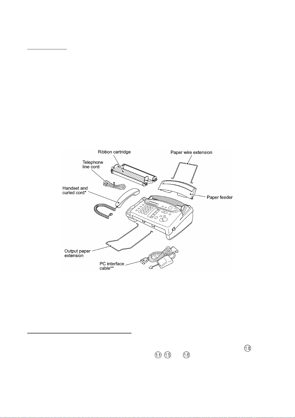
nn Preparation
Prior to proceeding to the disassembly procedure,
(1) Unplug
- the modular jack of the telephone line,
- the modular jack of the curled cord* (and remove the handset*),
- the PC interface cable** and
- the modular jack of an external telephone set if connected. (Not shown below.)
(2) Remove
- the paper wire extension and paper feeder
- the output paper extension, and
- the ribbon cartridge.
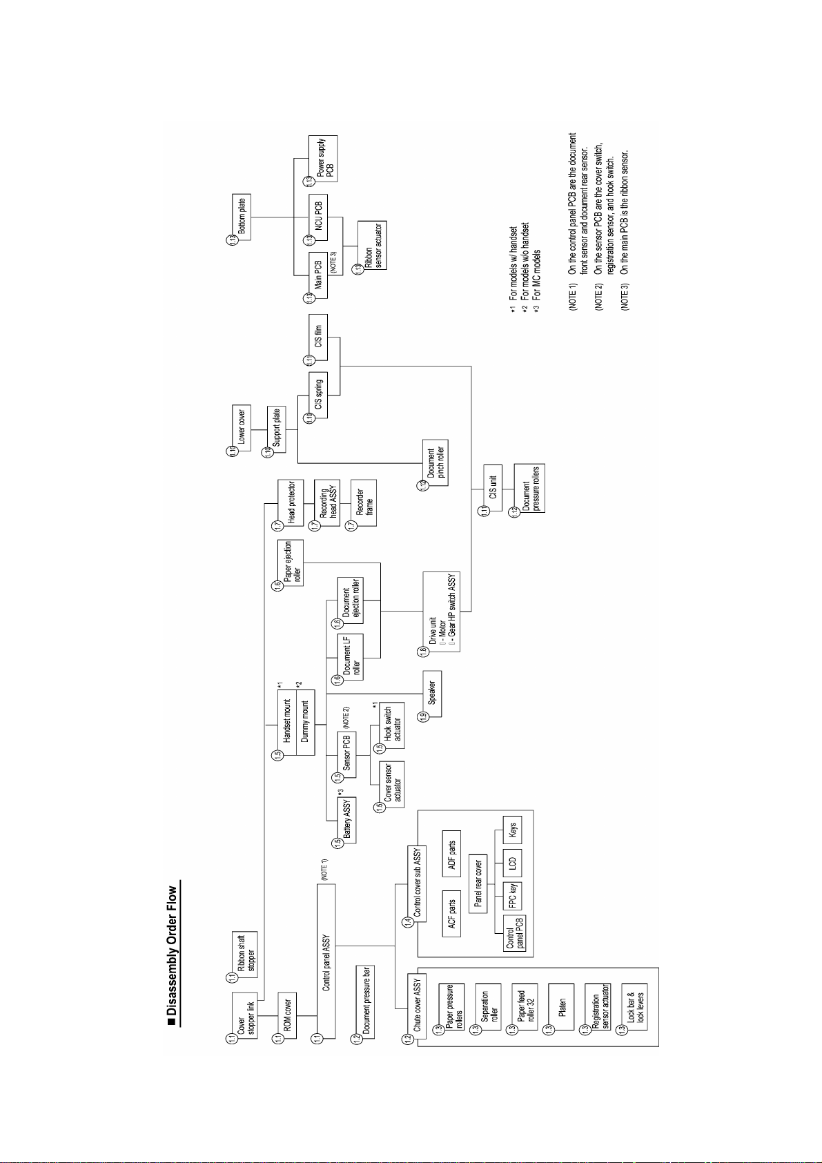
nn How to Access the Object Component
• On the next page is a disassembly order flow which helps you access the object components.
To remove the motor, for example, first find it on the flow and learn its number ( in this
case). You need to remove parts numbered , , and so as to access the motor.
• Unless otherwise specified, the disassembled parts or components should be reassembled in
the reverse order of removal.
*Not provided on the FAX-T72.
**Provided on the MFC660MC.
IV - 3
IV - 4
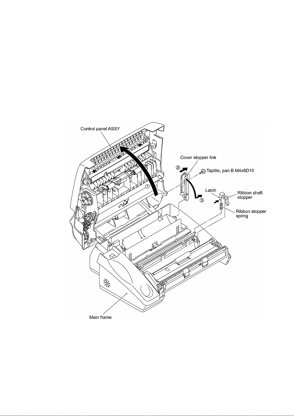
1.1 Cover Stopper Link, Ribbon Shaft Stopper, ROM Cover, and Control Panel ASSY
(1) Open the control pane ASSY (in the direction of arrow •).
(2) Remove the screw from the cover stopper link. Pull the link outwards (arrow ‚) to release it
from the control panel ASSY and then turn it to the front (arrow ƒ) to remove.
(3) Press the latch of the ribbon shaft stopper with a screwdriver to release it from the main
frame. The spring also comes off.
IV - 5
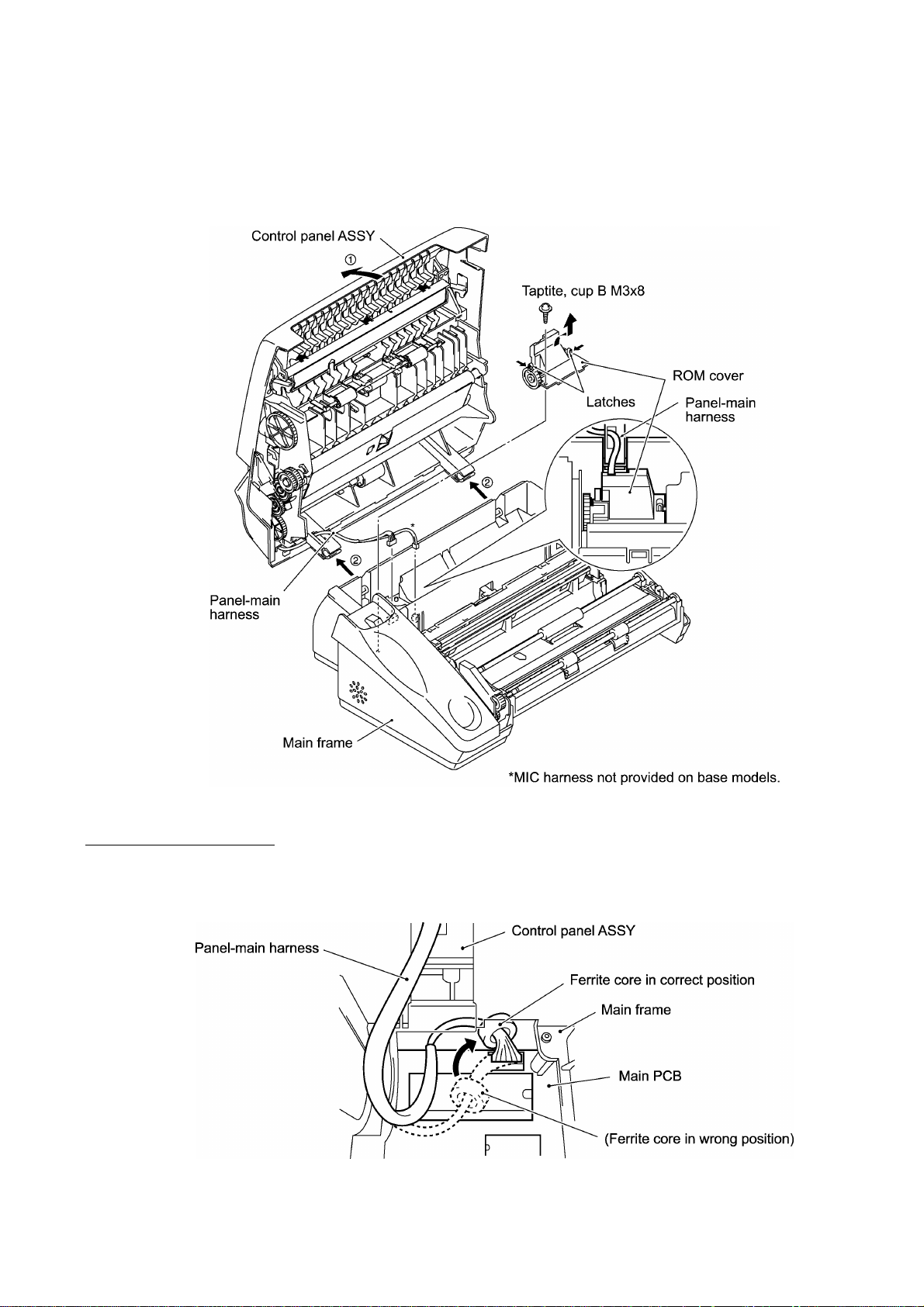
(4) Remove the screw from the ROM cover. Unlatch the ROM cover and take it up.
(5) Disconnect the panel-main harness from the main PCB.
nn Reassembling Notes
• When connecting the panel-main harness to the main PCB, place the ferrite core as illustrated
below.
IV - 6
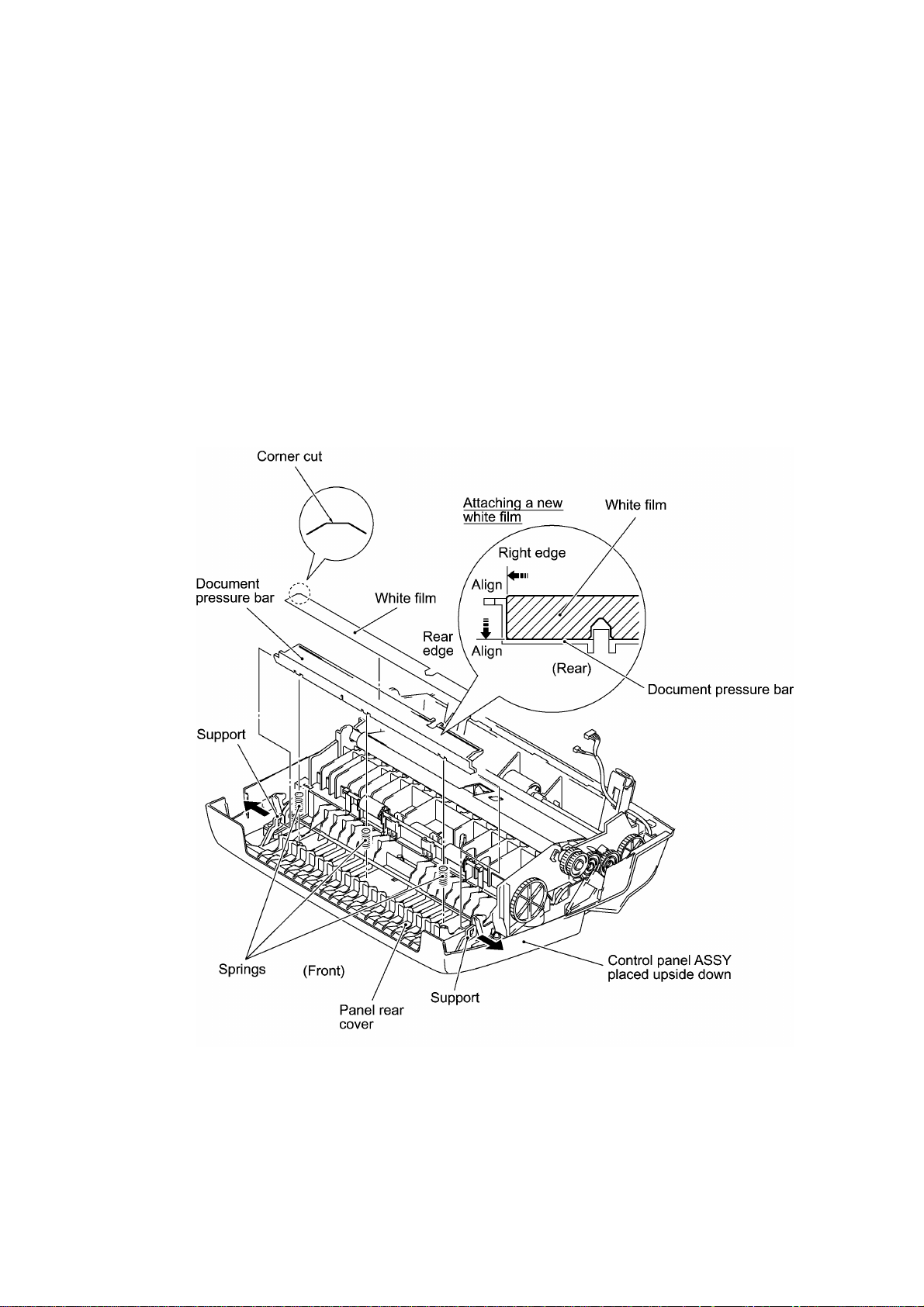
1.2 Disassembly of the Control Panel ASSY (Document pressure bar and chute cover ASSY)
(1) Place the control panel ASSY upside down.
(2) Pull either of the supports provided on the panel rear cover outwards and lift up the document
pressure bar. The three springs also come off.
(3) To replace the white film of the document pressure bar, remove it.
NOTE: Once removed, the white film will become unusable and a new one will have to be put
back in.
NOTE: When attaching a new white film to the document pressure bar, align the right and
rear edges as shown below.
IV - 7
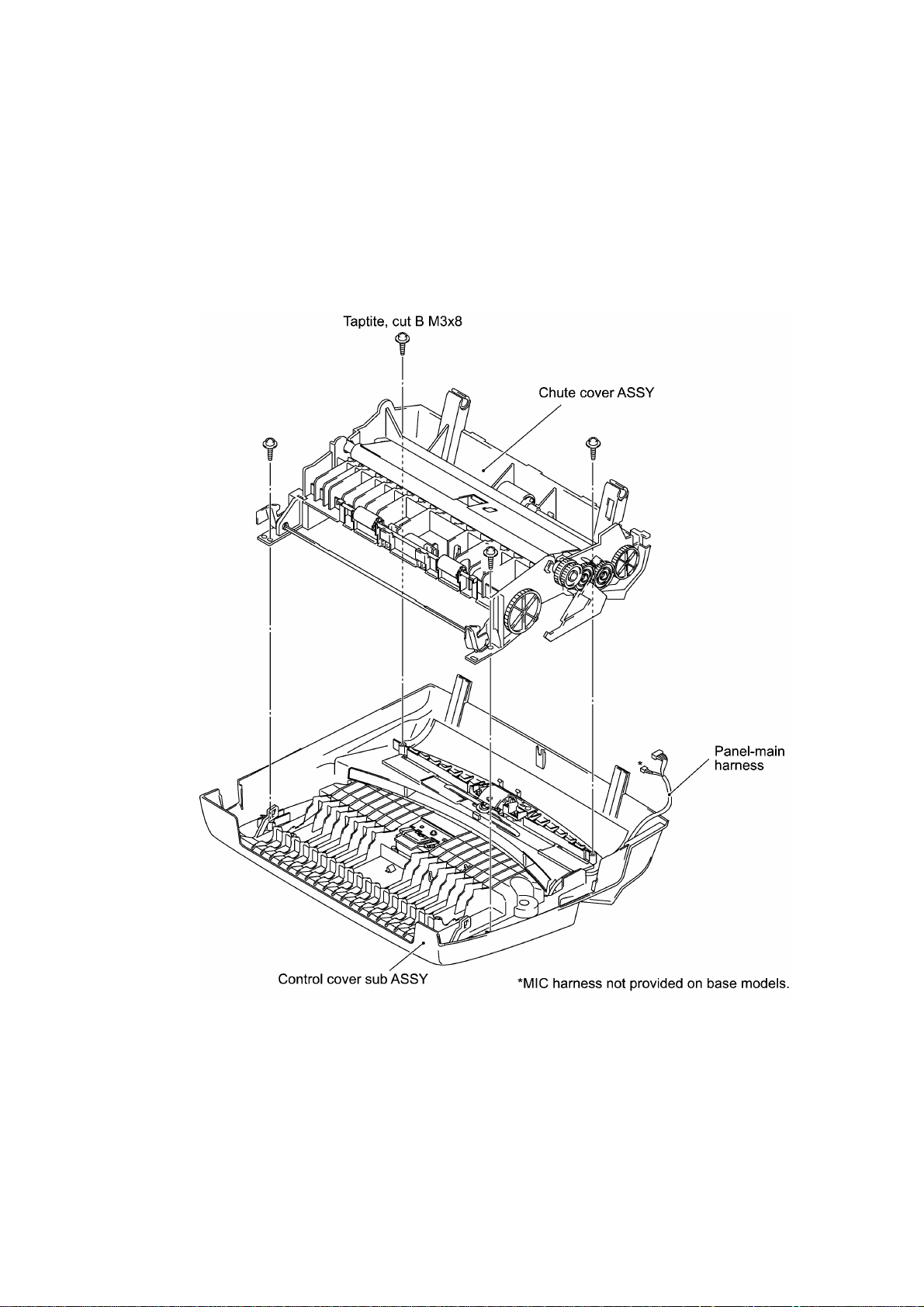
(4) Remove four screws from the chute cover ASSY.
(5) Slightly lift up the chute cover ASSY and remove the panel-main harness from the chute
cover ASSY.
IV - 8
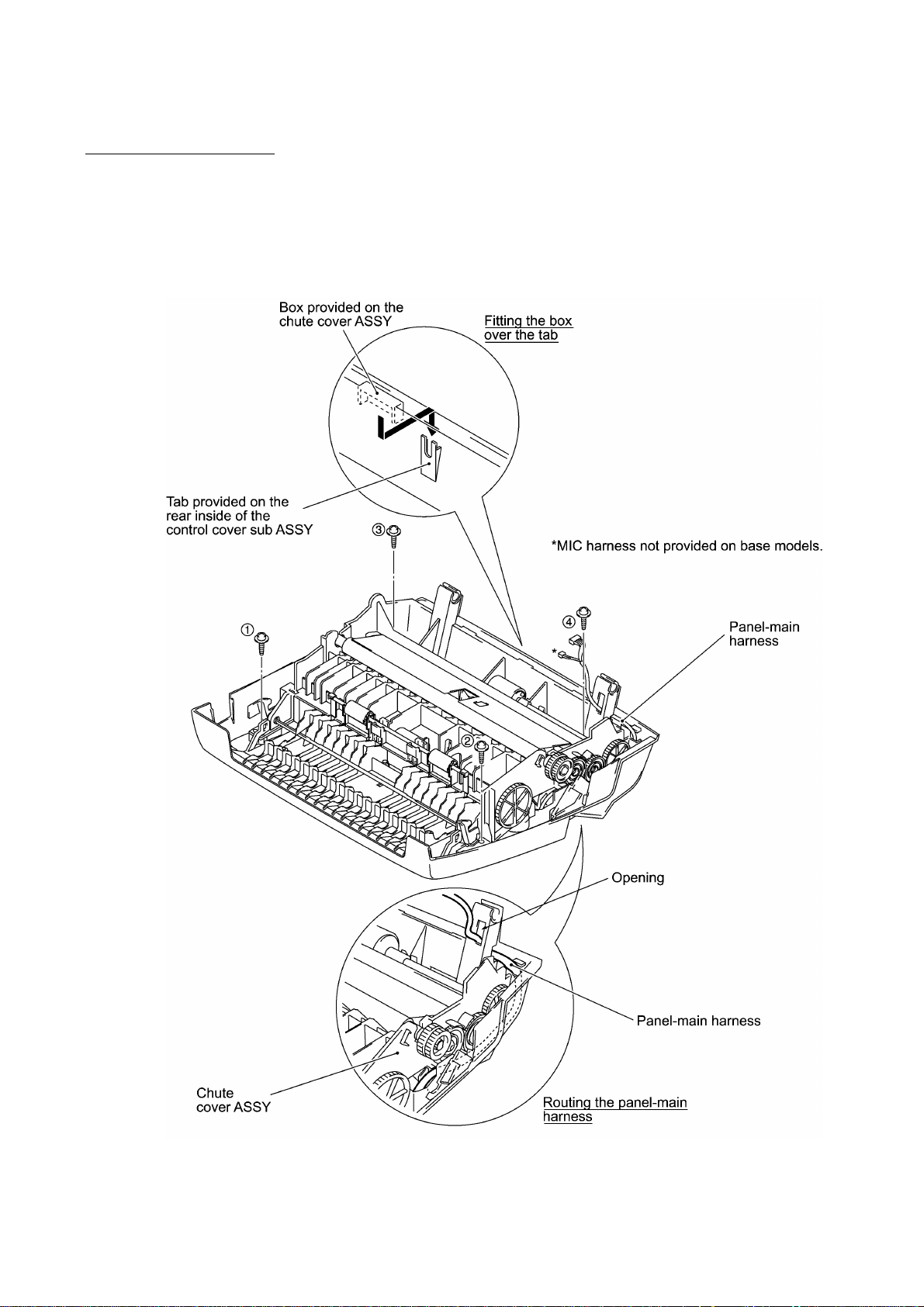
nn Reassembling Notes
• When reinstalling the chute cover ASSY, first pass the panel-main harness through the opening
provided in the chute cover ASSY and route it as shown below.
Then place the chute cover ASSY onto the control sub ASSY so that the box on the chute
cover ASSY becomes fitted over the tab on the control cover sub ASSY.
Tighten four screws in the order shown below.
IV - 9
 Loading...