

Page 1
•
SERVICE
MANUAL
FOR
V SERIES
OVERLO
EF4-V41 •
EF4-V71 •
EF4-V72 • V82 • MA4
CK
SEWING
V51
V81
• MA4-
• MA4-
MACHINE
V61
V91
-V
92
Page 2
(
PRODUCT
(
SPECIFICATION
SPECIFICATION
LIST
CONTENTS
CODE SETTING STANDARD ) · · · · · · · · · · · · · · · · · · · · · · · · · · ·
) · · · · · · · · · · · · · · · · · · · · · · · · · · · · · · · · · · · · · · · · · · · · · · · · · · · · · · · · · · · · · · · · 4
( MECHANICAL DESCRIPTIONS )
III Needle
1Z1
Under
00
Over
1!1
Double
liD
Knife
[§]
Presser
[1] Feed mechanism
[I]
Upper
00
.
Lubrication
bar
mechanism . . . . . . . . . . . . . . . . . . . . . . . . . . . . . . . . . . . . . . . . . . . . . . . . . . . . . . . . . . . . . . .
looper
looper
mechanism . . . . . . . . . . . . . . . . . . . . . . . . . . . . . . . . . . . . . . . . . . . . . . . . . . . . . . . . . . . . . . . . . . . . 20
feed mechanism
mechanism
mechanism . . . . . . . . . . . . . . . . . . . . . . . . . . . . . . . . . . . . . . . . . . . . . . . . . . . . . . . . . . . .
chain
stitch
looper
foot
mechanism . . . . . . . . . . . . . . . . . . . . . . . . . . . . . . . . . . . . . . . . . . . . . . . . . . . . . . . . . . . . . . .
.... ~ . . . . . . . . . . . . . . . . . . . . . . . . . . . . . . . . . . . . . . . . . . . . . . . . . . . . . . . . . . . . . . . . 23
. . . . . . . . . . . . . . . . . . . . . . . . . . . . . . . . . . . . . . . . . . . . . . . . . . . . . . . . . . . . . . . . . . . . . . . . . . 29
..............................
mechanism (V61, V91, V92)
...............................................................
· · · · · · · · ·
( DISASSEMBLY ) · · · · · · · · · · · · · · · · · · · · · · · · · · · · · · · · · · · · · · · · · · · · · ·
··
· · · · · · · ·
··
· · · · · · · · ·
~
..............................
...................................
··
· · · · · · · · · · · · · · · · · · · ·
··
· · · · · · · · · · ·
··
· · · · · · · · 30
III Covers . . . . . . . . . . . . . . . . . . . . . . . . . . . . . . . . . . . . . . . . . . . . . . . . . . . . . . . . . . . . . . . . . . . . . . . . . . . . . .
IZ1
00
Presser
Knife
foot
mechanism
mechanism . . . . . . . . . . . . . . . . . . . . . . . . . . . . . . . . . . . . . . . . . . . . . . . . . . . . . . . . . . . . . . . . . . . . 32
...............................................................
..
. 18
16
16
17
19
21
25
30
31
1!1
Under
liD
Over
[§]
Double
[1]
Needle
[I]
Feed mechanism . . . . . . . . . . . . . . . . . . . . . . . . . . . . . . . . . . . . . . . . . . . . . . . . . . . . . . . . . . . . . . . . . . . . . 37
II]
Upper
looper
looper
feed mechanism . . . . . . . . . . . . . . . . . . . . . . . . . . . . . . . . . . . . . . . . . . . . . . . . . . . . . . . . . . . . . . . 38
mechanism
mechanism . . . . . . . . . . . . . . . . . . . . . . . . . . . . . . . . . . . . . . . . . . . . . . . . . . . . . . . . . . . . . . 34
chain
stitch
looper
bar
mechanism . . . . . . . . . . . . . . . . . . . . . . . . . . . . . . . . . . . . . . . . . . . . . . . . . . . . . . . . . . . . . . . 36
.............................................................
mechanism . . . . . . . . . . . . . . . . . . . . . . . . . . . . . . . . . . . . . . . . . . . . . . . . . 35
( ASSEMBLY ) · · · · · · · · · · · · · · · · · · · · · · · · · · · · · · · · · · · · · · · · · · · · · · · · · · · · · · · · · · · · · · · · · · · · · · · · · ·
III
Upper
IZ1
Feed mechanism . . . . . . . . . . . . . . . . . . . . . . . . . . . . . . . . . . . . . . . . . . . . . . . . . . . . . . . . . . . . . . . . . . . . . 45
00
Needle
1!1
Under
[§] Over
00
[1]
[I]
feed
mechanism
bar
mechanism . . . . . . . . . . . . . . . . . . . . . . . . . . . . . . . . . . . . . . . . . . . . . . . . . . . . . . . . . . . . . . . 48
looper
looper
Double
Knife
mechanism . . . . . . . . . . . . . . . . . . . . . . . . . . . . . . . . . . . . . . . . . . . . . . . . . . . . . . . . . . . . . . . . . . . . 57
Presser
mechanism . . . . . . . . . . . . . . . . . . . . . . . . . . . . . . . . . . . . . . . . . . . . . . . . . . . . . . . . . . . . .
mechanism . . . . . . . . . . . . . . . . . . . . . . . . . . . . . . . . . . . . . . . . . . . . . . . . . . . . . . . . . . . . . . 52
chain stitch
foot
mechanism . . . . . . . . . . . . . . . . . . . . . . . . . . . . . . . . . . . . . . . . . . . . . . . . . . . . . . . . . . . . . . .
...............................................................
looper
mechanism . . . . . . . . . . . . . . . . . . . . . . . . . . . .
..
. . . . . . . . . . . . . . . . . . . 54
33
41
41
SO
59
00
Covers . . . . . . . . . . . . . . . . . . . . . . . . . . . . . . . . . . . . . . . . . . . . . . . . . . . . . . . . . . . . . . . . . . . . . . . . . . . . . .
61
Page 3
( STANDARD
[I]
Adjusting
lZ1
Adjusting
rn1
Adjusting
1!1
Adjusting
[§]
Adjusting
[§]
Adjusting
11]
Adjusting
00
Adjusting
00
Adjusting
1m!
Adjusting
Ill]
Adjusting
H2l
Adjusting
111
Adjusting
Ml
Adjusting
1m
Adjusting
ADJUSTMENTS ) ·······
the
height
the
under
the
over
the
chain stitch looper, chain stitch needle guards
the
backward and
the
presser
the
height
the
height
the
positions
the
position
the
horizontal feeding
the
standard position
the
horizontal feed
the
standard
the
height
and location
looper,
looper
of
of
of
the
.............................................................
foot
............................................................
the
knife
the
feed
of
the
of
the
of
the
the
upper feed bar
movable needle guard, and needle guard
forward
dog
needle-thread take-up and
looper
timing
of
amount
vertical feeding
· · · · · · ·
of
the
needle . . . . . . . . . . . . . . . . . . . . . . . . . . . . . . . . . . . . . . . .
movement
. . . . . . . . . . . . . . . . . . . . . . . . . . . . . . . . . . . . . . . . . . . . . . . . . . . . . .
. . . . . . . . . . . . . . . . . . . . . . . . . . . . . . . . . . . . . . . . . . . . . . . . . .
thread take-up
(position
the
horizontal feeding (level feed adjust arm) . . . . . . . . . .
. . . . . . . . . . . . . . . . . . . . . . . . . . . . . . . . . . . . . . . . . . . . . . . . .
··········································
of
of
..
..
.............................................
(F)
. . . . . . . . . . . . . .
(B)
and
(F)
. . . . . . . . . . . . . . . . . . . 66
the
chain stitch
the
.....................................
the
level feed eccentric wheel) . . . . . . . . 76
. . .
.. . ..
looper
needle thread
.. . ..
.. ..
..
.. .. . .. . ..
. . . . . . . . . . . . . . . .
guide . ..
..
. . . . . . 75
..
. . .
..
62
62
63
65
67
68
71
72
76
77
77
78
79
11§)
Adjusting
lll1
Adjusting
1m]
Adjusting
Iii
Adjusting
(
TROUBLESHOOTING
[1]
Needle
lZ1
Looper
rn1
Needle breakage . . . . . . . . . . . . . . . . . . . . . . . . . . . . . . . . . . . . . . . . . . . . . . . . . . . . . . . . . . . . . . . . . . . . . 88
1!1
Improper
1m
Improper
[§] Puckering
11]
Slippage
00
Double scooping (overlocking) . :
the
the
the
the
thread
thread
thread
chaining-off
...........................................................................
cloth
clearance between
vertical feed
differential
clearance
ratio
between
the
upper feed
amount
of
the
upper feed
........................................................
the
cloth plate and
dog
and
the
dog
. . . . . . . . . . . . . . . . . . . . . . . . . . . . . . .
the
needle plate . . . . . . . . . . . . . . . . . . . . 83
lower
feed
dog
. . . . . . . . . . . . . 80
) · · · · · · · · · · · · · · · · · · · · · · · · · · · · · · · · · · · · · · · · · · · · · · · · · · · · · · · · · · · · · · · 84
breakage . . . . . . . . . . . . . . . . . . . . . . . . . . . . . . . . . . . . . . . . . . . . . . . . . . . . . . . . . . . . . . 84
breakage
tension
.......................................................................
..............................................................
..............................................................
................................................................
......................................................
81
82
85
88
88
89
90
90
(
NEEDLE
(
MATERIALTHICKNESSANDSTITCHWIDTH
TIMINGGAUGETABLE
(
SIZE
AND
UPPER
)
LOOPER
) · · · · · · · · · · · · · · · · · · · · · · · · · · · · · · · · · · · · · · · · · · · · · · ·
·································
) · · · · · · · ·
··
· · · · · · · · · · · · · · · · · · · ·
···························
···
91
· · · · 92
93
Page 4
PRODUCT
SPECIFICATION
CODE SETTING STANDARD
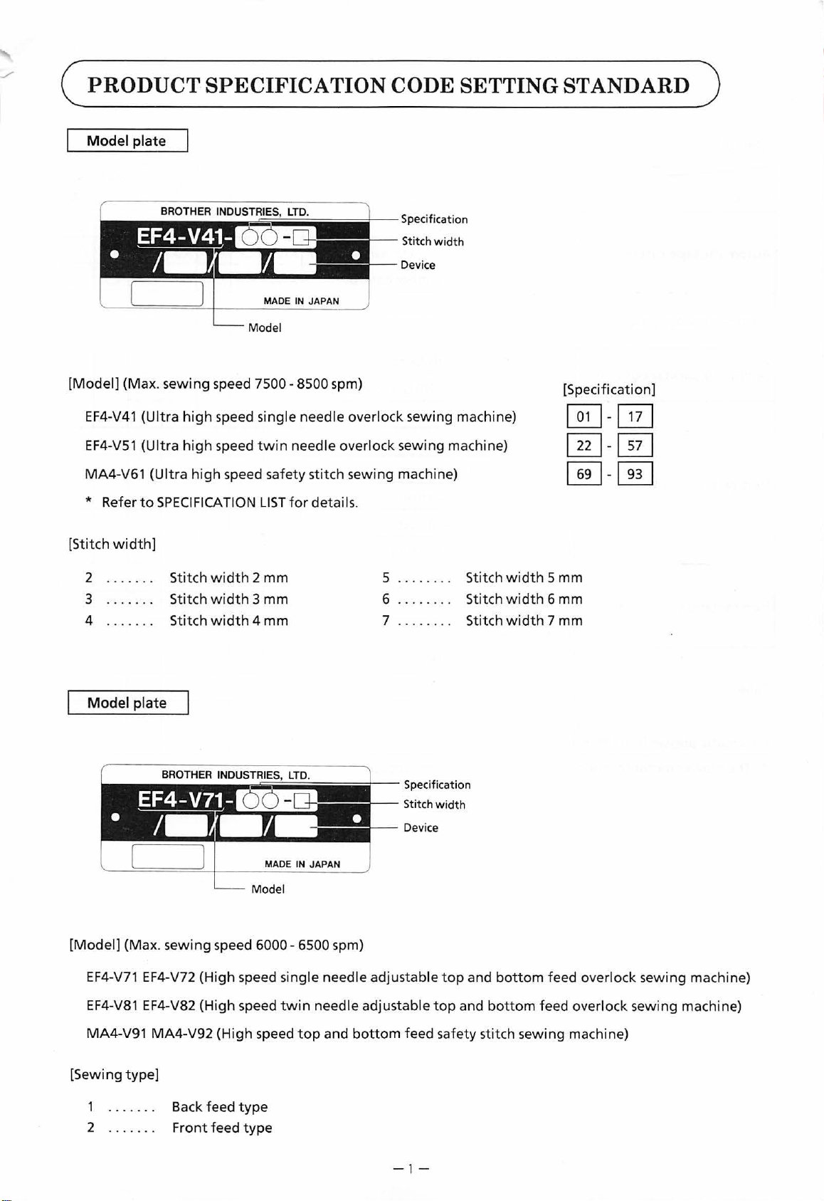
Model
[Model]
EF4-V41
EF4-V51
MA4-V61
* Refer
[Stit
ch
plate
(Max. sewing speed
(Ultra
high
speed single needle
(Ultra
high
speed
(Ultra
high
to
SPECIFICATION
width]
Specification
Stitch
width
Device
MADE IN JAPAN
7500-8500
twin
speed safety stitch sewing machine)
LIST
spm)
over
lock sewing machine)
needle overlock sewing machine)
for
details.
[Specification]
~-0
[ill-
[E)
@]-[ill
2 ......
3
4
......
Model
[Model]
EF4-
.
Stitch wid
Stitch
.
Stitch
plate
(Max. sewing speed
V71
EF4-V72 (High speed single needle adjustable
th 2 mm
width 3 mm
width
4 mm
~~ii;;;i~iiiiiiiiiiiiil
MADE IN JAPAN
6000-6500
--
spm)
.......
5
6
7
.......
Specification
Stitch
Device
.
.
width
top
Stitch widt
width
Stitch
width
Stitch
and
bottom
h 5 mm
6 mm
7 mm
feed overlock sewing machine)
EF4-V81
MA4-V91 MA4-V92
[Sewing
2
type]
......
EF4-V82 (Hi
Back feed
.
Front feed
gh
speed
(High
type
type
twin
speed
needle adjustable
top
and
bottom
top
and
bottom
feed safety stitch sewing machine)
- 1-
feed ove rlock sewing machin
e)
Page 5
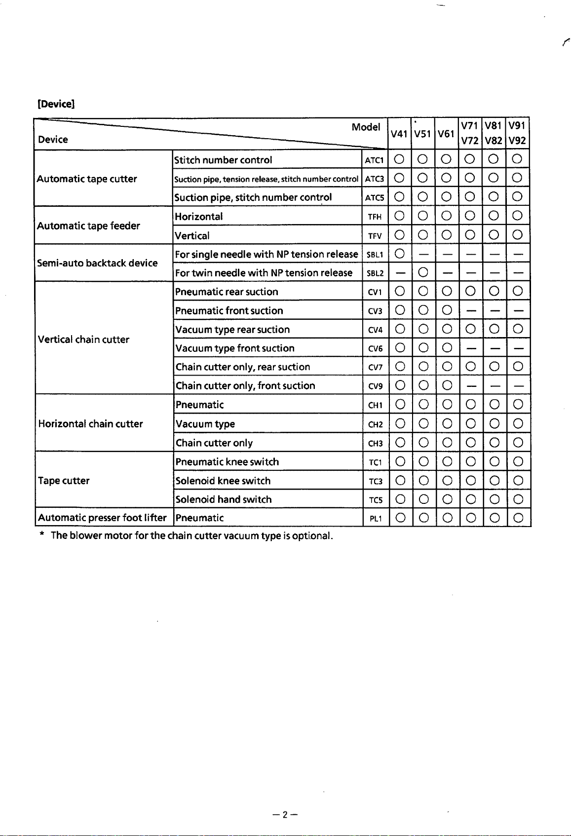
[Device]
Device
Model
V41
.
V51
V61
V71
V72
V81
V91
V82 V92
Automatic
Automatic
Semi-auto backtack device
Vertical chain
Horizontal chain
tape
tape
cutter
cutter
feeder
cutter
Stitch number control
Suction pipe, tension release, stitch number control
Suction pipe, stitch number
Horizontal
Vertical
For single needle
For
twin
needle
Pneumatic rear suction
Pneumatic
Vacuum type rear suction
Vacuum
Chain cutter only, rear suction
Chain
Pneumatic
Vacuum type
Chain cutter only
type
cutter
front
front
only,
with
with
suction
suction
front
cont~ol
NP
tension release
NP
tension release
suction
ATC1
0 0 0 0 0
ATC3
0 0 0
ATCS
0 0 0
TFH
0 0 0 0 0 0
TFV
0 0 0 0 0 0
SBL1
SBL2
CV1
CV3
CV4
CV6
CV7
CV9
CH1
CH2
CH3
-
0
-
-
0 -
0 0 0 0 0 0
0 0 0
0
0
0
0 0 0
0 0 0 0 0 0
0 0 0
0 0 0 0 0 0
0 0 0 0 0 0
0 0 0 0 0 0
0 0
0
0 0
- - -
-
-
-
-
0
0
- -
-
-
-
0
0
-
-
0
-
Tape
cutter
Automatic presser
* The
blower
motor
foot I ifter
for
the
Pneumatic knee switch
Solenoid knee switch
Solenoid hand switch
Pneumatic
chain cutter vacuum type
is
optional.
TC1
0 0 0 0
TC3
0
TCS
0 0
PL
1
0 0
0
0
0 0 0 0 0
0 0 0 0
0 0 0 0
-2-
Page 6
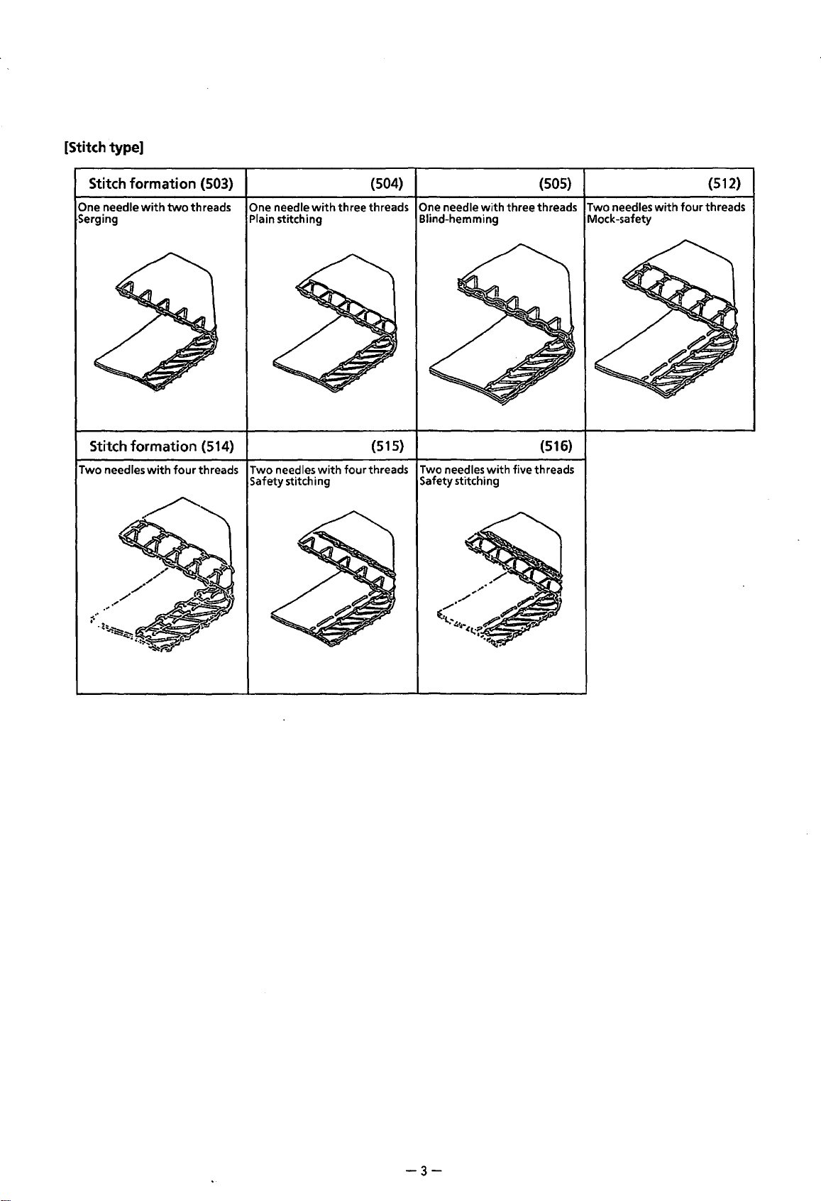
[Stitch type]
Stitch
formation
One needle
Serging Plain stitching Blind-hemming Mock-safety
Stitch
Two needles
with
formation
with
(503)
two
threads One needle
(514)
four
threads Two needles
Safety stitching Safety stitching
with
with
(504)
three threads
One
needle
(515)
four threads Two needles
with
with
(505)
three threads Two needles
(516)
five threads
with
four threads
(512)
-3-
Page 7
c
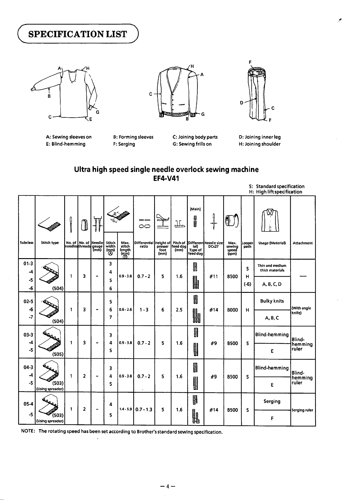
SPECIFICATION
A:
Sewing sleeves on
E:
Blind-hemming
LIST )
B:
Forming sleeves
F:
Serging
F
c
0
C:
Joining body parts
G:
Sewing frills on
0:
Joining
inner
leg
H: Joining shoulder
Subclass
01-3
-4
-5
-6
02-5
-6
-7
03-3
-4
-5
~
Stitch
type
needle=
a
(504)
a
(504)
8
(505)
Ultra
[]
~
No.
of
No.
of
Needle
hread5
1
3
1
3
1
3
high
speed
4;,
~.<
*
Stitch
width
~auge
mm)
(®)
3
4
-
5
6
5
6
-
7
3
4
-
5
single·needle
EF4-V41
==
:t
00
--
Max. Differential Height
stitch
length
(~)
0.9-3.8
0.6-2.6
0.9-3.8
ratio
0.7-2
1-3
0.7-2
presser feed dog
foot
(mm)
5
6
5
overlock
lr
~
of
Pitch
of
(mm)
1.6
2.5
1.6
[Main)
m
I
Dlfferen
Ia
I)
Type
of
feed
dog
H
Ill
n
Ill
n
II
sewing
+
Needle size
0007
#11
#14
#9
machine
l)j
Max.
Looper Usage (Material)
(spm)
8500
8000
8500
path
s
H
(-6)
H
s
s=
S:
Standard specification
H: High
lift
specification
m
Thin and medium
thick materials
A, B,C, D
Bulky knits
A,B,C
Blind-hemming
E
Attachment
-
(With
angle
knife)
Blindhemming
ruler
04-3
-4
-5
~3)
(Using spreader)
05-4
-5
~3)
(Using spreader)
NOTE:
The
rotating
1 2
1
2
speed has been set according
3
0.9
·3.8
4
-
5
4
-
5
0.7-2
1.4·5.9
0.7-1.3
to
Brother's standard sewing specification.
5 1.6
5 1.6
-4-
m
II
'
k
#9
#14
8500
8500
Blind-hemming
s
Serging
s
Blindhemming
E
F
ruler
Serging ruler
Page 8
H
-~
F
r
t-C
c
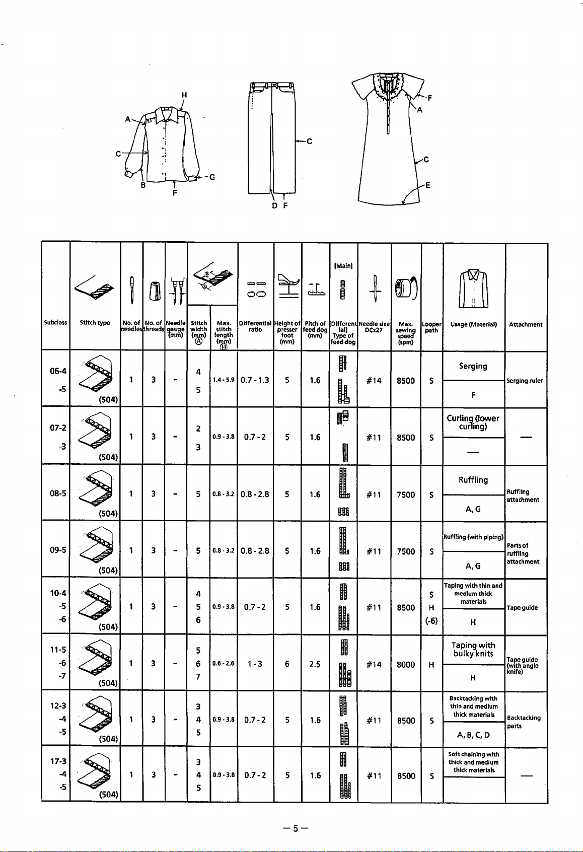
Subclass
06--4
-5
07-2
-3
<,
Stitch type
ij
No.
of
t~eedle!
1
~
(504)
1
~
(504)
F
l]
lf
No.
of
Needle Stitch Max.
hreads
~auge
mm)
3
-
3
-
G
~
width
stitch
length
(®)
(~~)
4
1.4-5.9
5
2
0.9-3.8
3
==
00
Differential
ratio presser
0.7-1.3
0.7-2
r
0 F
~
--
~eight
of
Pitch
feedd99
foot
(mm)
5 1.6
5 1.6
ir
~
(mm)
of
[Main)
~
I
Differen1
ial)
Type
of
feed dog
p
k
~
I
+
Neediesize
DCx27
#14
#11
E
~
Max. Looper
path
s=
(spm)
8500
8500 s
s
m
Usage
(Material)
Serging
Serging ruler
F
Curlin~
(lower
curing)
-
Attachment
-
08-5
~
09-5
~
10-4
-5
~
-6
11-5
~·
-6
-7
12-3
~·
-4
-5
17-3
~·
-4
-5
(504)
(504)
(504)
(504)
(504)
(504)
1 3
1 3
1 3
1
1
1
Ruffling
s
A,G
Ruffling (with piping)
s
A,G
Taping
with
medium thick
s
H
s
materials
Taping
bulky knits
Backtacking
thin
and medium
thick materials
A,B,C,D
Soft chaining
thick
and
thick materials
thin and
H
with
H
medium
with
with
Ruffling
attachment
Parts
of
ruffling
attachment
Tape guide
Tape guide
(with angle
knife)
Backtacking
parts
-
0.8-3.2
5
-
0.8-2.8
5
1.6
[
#11
7500
m
0.8-3.2
5
-
0.8-2.8
5 1.6
[
#11
7500
m
4
0.9-3.8
5
-
6
5
3
-
3
-
0.6-2.6
6
7
3
0.9
4
5
·3.8
0.7-2
1-3
0.7-2
5 1.6
6 2.5
5 1.6
n
#11
~
H
#14
Ill
n
#11
8500
(-6)
8000 H
8500
D
3
3
-
0.9-3.8
4
5
0.7-2
5 1.6
n
#11
~
8500 s
-5-
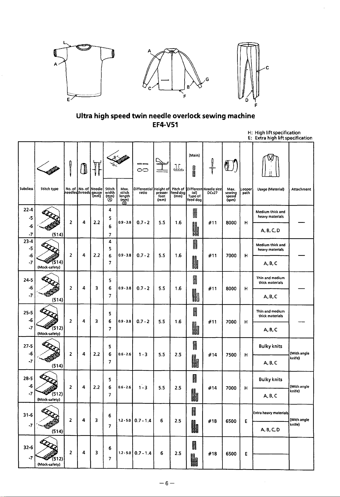
Page 9
G
F
<:,
Subclass
Stitch
22-4
-5
··,
-6
-~
.
--...
-7
23-4
-5
-6
a.
-7
(Mock-safety)
24-5
-6
•'
,·,"'-
-7
Ultra high speed
[]
~
type
No.
of
No.
hreads
reedle
4
2
:
{514)
2
4 2.2
(5
4)
,
~
(514)
4
2
'ff
of
Needle Stitch
~auge
mm)
2.2
3 6
~
~<
Max. Differential
width
stitch ratio
length
(®)
(~)
4
5
0.9·3.8
6
7
4
5
0.9
·3.8
6
7
5
0.9·3.8
7
twin
needle overlock sewing machine
EF4-V51
(Main}
==
00
~
--
!Height
presser
foot
(mm}
lr
!:::!::!:::!::>
Pitch
of
feedd~
(mm)
0
+
e
of
Oifferen
Needle size
Ia
I]
DCx27
of
Type
feed dog (spm)
H
0.7-2
5.5
1.6
#11
I
H
0.7-2
0.7-2
5.5
5.5
1.6
1.6
#11 7000 H
lit
n
#11
Ill
eD)
Max. Looper
path
sewlnJ'
spee
8000
8000
H:
High
E:
lift
Extra high
m
Usage
(Material)
Medium thick and
heavy materials
H
A,B,C,D
Medium thick and
heavy materials
A,B,C
Thin and medium
thick materials
H
A,B,C
specification
lift
specification
Attachment
-
-
-
25-5
-6
~
-7
(Mock-safety)
27-5
-6
-~
·:·--..
-7
28-5
-6
~
-7
31-6
-7
32-6
-7
{512)
(Mock-safety)
-~
{514)
~2)
(Mock-safety)
{512)
(514)
2
4
3
4
2
2
2
2
2.2
4
2.2
4
3
4
3
5
0.9·3.8
6
7
5
0.6·2.6
6
7
5
0.6·2.6
6
7
6
1.2·
7
5.0
0.7-2
1-3
1-3
0.7-1.4
1.6
5.5
2.5
5.5
5.5 2.5
6 2.5
n
#11 7000 H
Ill
n
#14
lh
H
#14
•
H
#18
7500 H
7000 H
6500
Thin and medium
thick materials
A,B,C
Bulky knits
A,B,C
Bulky knits
A,B,C
Extra heavy materials
E
A,B,C,D
(With
knife)
(With
knife)
(With
knife)
-
angle
angle
angle
•
6
1.2.
5.0
7
0.7-1.4
6
2.5
H
lh
#18
6500 E
-6-
Page 10
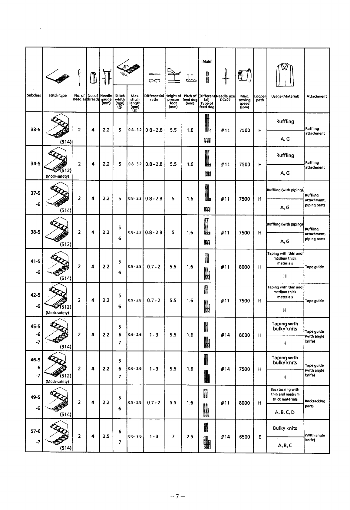
Subclass
33-5
<f;,
Stitch
width
('(&')
5
~<
[]
(514)
j
No.
of
No.
of
hreads
t~eedle!
2 4 2.2
~
Needle
~auge
mm)
~
Stitch type
.·~
·
.........
==
00
MalC.
Differential Height
stitch ratio presser
length
(~)
0.8-3.2
0.8-2.8
~
--
foot
(mm)
5.5 1.6
of
Pitch
feed
lr
~
(mm)
(Main)
of
Differen1
dog ial)
Type
feed dog
I
m
~
I
of
+
Needle size
DClC27
#11
f)j
MalC.
Looper
sew~
spe
(spm)
7500 H
path
m
Usage
(Material) Attachment
Ruffling
Ruffling
A,G
attachment
34-5
2 4
2.2
~2)
(Mock-safety)
37-5
--~
·:·-.....
-6
38-5
~
41-5
.,~
-6
42-5
-6
~2)
(Mock-safety)
45-5
-6
,·,
-~
._
........
-7
(514)
(512)
(514)
(514)
2 4
2 4
2
2 4
2
2.2 5
2.2
4 2.2
2.2
4
2.2 6
0.8-3.2
5
0.8-2.8
5.5 1.6
[
#11
7500 H
m
0.8-3.2
0.8-2.8
5
1.6
[
#11
7500 H
m
5
0.8-3.2
0.9-3.8
0.8-2.8
0.7-2
6
5
6
5 1.6
5.5
1.6
[
#11
m
n
#11 8000 H
7500 H
Ill
5
0.9·3.8
6
5
0.6-2.6
7
0.7-2
1-3
5.5
5.5 1.6
1.6
H
Ill
H
HI
#11 7500
#14
8000
Ruffling
A,G
Ruffling
(with
A,G
Ruffling (with piping)
A,G
Taping
with
medium thick
materials
Taping
with
medium thick
H
H
materials
Taping
bulky knits
H
H
H
piping)
thin
thin
with
and
and
Ruffling
attachment
Ruffling
attachment,
piping parts
Ruffling
attachment,
piping parts
Tape guide
Tape guide
Tape guide
(with
angle
knife)
46-5
-6
-7
~2)
(Mock-safety)
49-5
~~~~.
-6
~
57-6
.~
-7
2 4
2 4
(514)
2 4
(514)
2.2
2.2
2.5
5
0.6-2.6
6
7
5
0.9-3.8
6
1-3
0.7-2
5.5 1.6
5.5 1.6
H
Ill
H
Ill
6
0.6-2.6
7
1-3
7
n
2.5
Ill
-7-
#14
#11
#14
7500 H
8000 H
6500 E
Taping
with
bulky knits
H
Backtacking
thin and medium
thick materials
Bulky knits
with
A,B,C,D
A,B,C
Tape guide
(with
angle
knife)
Backtacklng
parts
(With angle
knife)
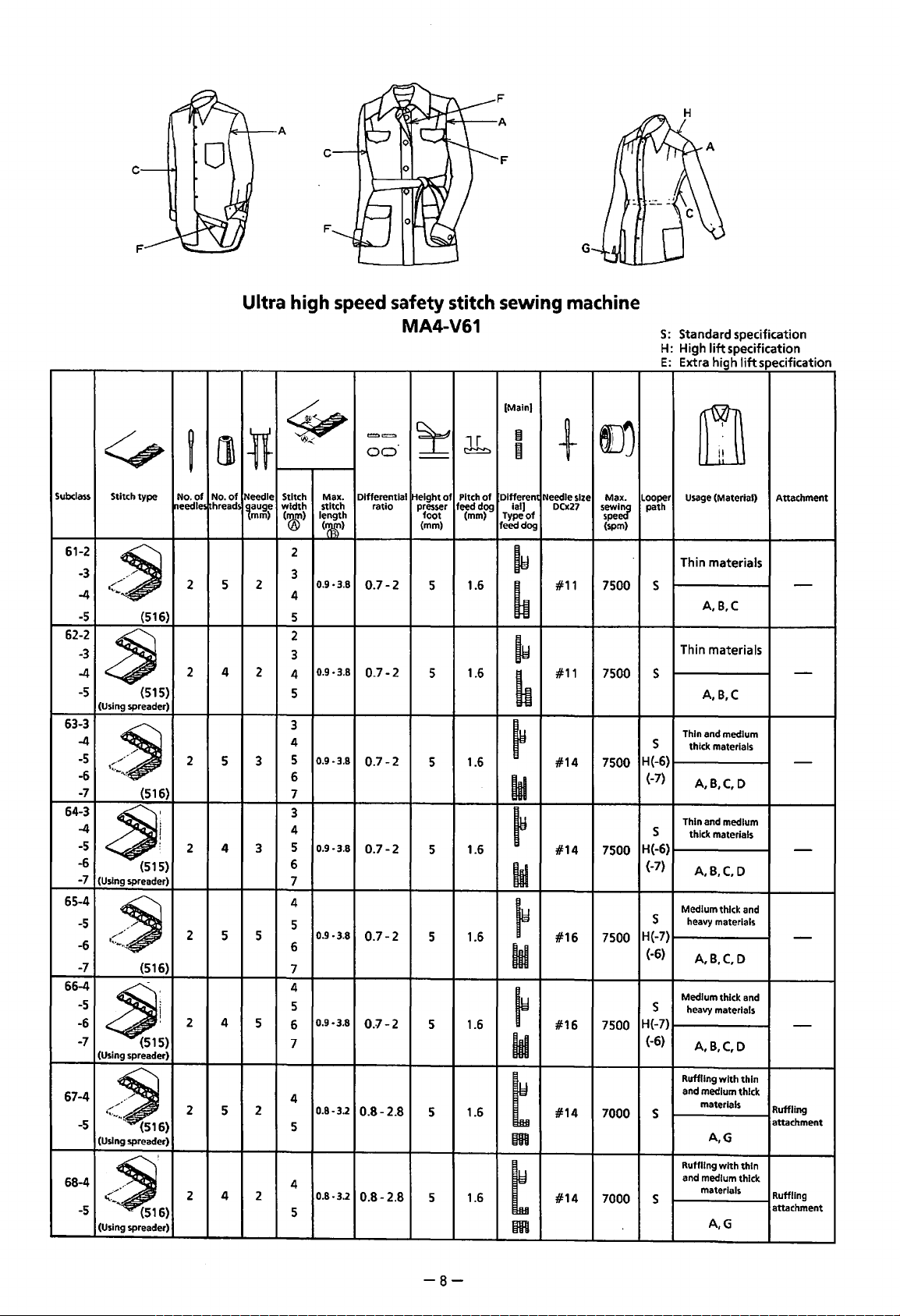
Page 11
c
F
G
Subclass
61-2
-3
-4
-5
62-2
-3
-4
-5
63-3
-4
-5
-6
-7
64-3
-4
-5
-6
-7
65-4
-5
-6
-7
66-4
-5
-6
-7
67-4
-5
68-4
-5
Ultra
<,
Stitch
type
~.
<'~
(516)
~
{515)
(Using spreader)
*r""··
·~·
-~
{516)
~~
(515)
(Using spreader)
·'-.·
..
>~
{516)
~~)
(Using spreader)
[l\
~
No.
of
No.
of
hread
~eedle!
2 5 2
2 4 2
2
5
2 4
2
5 5
2 4
2
5
Needle
<~6)
(Using spreader)
<~,6)
(Using spreader)
2 4 2
high
~
~
Stitch Max. Differential
width
(®)
2
3
4
5
2
3
4
5
3
4
5
6
7
3
4
5
6
7
4
5
6
7
4
5
6
7
4
5
4
5
stitch ratio
length
<mr>
0.9·3.8
0.9·3.8
0.9-3.8
0.9-3.8
0.9
0.9-3.8
0.8-3.2
0.8-3.2
lauge
mm)
3
3
5
2
speed
==
00
0.7-2
0.7-2
0.7-2
0.7-2
·3.8
0.7-2
0.7-2
0.8-2.8
0.8-2.8
safety
MA4-V61
~
--
[Height
of
presser
foot
(mm)
5
5
5 1.6
5
5 1.6
5 1.6
5 1.6
5 1.6
stitch
lr
~
Pitch
of
feedd!>Q
(mm)
1.6
1.6
1.6
sewing
[Main]
~
I
Differen
ial]
Type
feed dog (spm)
machine
+
Needle size Max.
DCx27
of
f)j
sew~
spe
~
#11 7500
~
IY
#11
7500 s
~
~
#14
7500
hi
~
#14
7500
ld
~
#16
7500
ld
~
#16
7500
ld
t
m
t
m
#14
#14
7000
7000
S:
Standard specification
H: High
E·
lift
Extra high
m
Looper
Usage
path
s
s
H(-6)
{-7)
s
H{-6)
{-7)
s
H{-7)
(-6)
s
H(-7)
(-6)
s
s
(Material)
Thin materials
A,B,C
materials
Thin
A,B,C
Thin and medium
thick materials
A,B,C,D
Thin and medium
thick materials
A,B,C,D
Medium thick and
heavy materials
A,B,C,D
Medium thick and
heavy materials
A,B,C,D
Ruffling
with
and medium thick
materials
A,G
Ruffling
with
and medium thick
materials
A,G
specification
lift
specification
Attachment
thin
Ruffling
attachment
thin
Ruffling
attachment
-
-
-
-
-
-
-8-
Page 12

A
F
c
[Main)
Subclass
69-4
-5
70-4
-5
71-5
-6
72-5
-6
75-5
76-5
77-5
-6
78-5
-6
<::,
Stitch
type
<.
....
.
~
(516)
[]
ij
No.
of
No.
~eedle!
hreads
2
5
2
4
of
~5)
(Using spreader)
(516)
2
2 4
5 5
t..,.,.
/~
~5)
(Using spreader)
(516)
2 5
2
4
"-·
...
-~
~
~
Stitch
Needle
width
lauge
mm)
('®)
4
3
5
4
3
5
5
6
5
5
6
3
5
3
5
Max.
stitch
length
(~)
0.8-3.2
0.8-3.2
0.8-3.2
0.8-3.2
0.8-3.2
0.8-3.2
~5)
(Using spreader)
5
2
5
<~
(516)
2 4
5
5
~5)
(Using spreader)
0.9-3.8
6
5
0.8-3.2
6
=..,..
00
Differential Height
0.8-2.8
0.8-2.8
0.8-2.8
0.8-2.8
0.8-2.8
0.8-2.8
0.8-2.8
0.8-2.8
~
--
ratio presser
foot
(mm)
5 1.6
5 1.6
5
5
5 1.6
5
5
5 1.6
db
of
Pitch
of
feed dog ial)
(mm)
1.6
1.6
1.6
1.6
0
a
l)j
+
Differen1
Needle size Max.
DCx27
#14
#14
#14
#14
#14
#14
#14
#14
5~~~
7000
7000
7000
7000
7000
7000
7000
7000
Type
of
feed dog (spm)
t
m
t
m
t
m
t
m
t
m
t
m
t
m
t
m
Looper
Usage
path
Ruffling
and medium thick
s
Ruffling
and medium thick
s
medium thick and
s
H
(-6)
medium thick and
s
H
(-6)
Ruffling (and piping)
s
Ruffling (and piping)
s
Ruffling (and piping)
with
s
and heavy materials
H(-6)
Ruffling (and piping)
with
s
and heavy materials
H(-6)
m
(Material)
with
materials
A,G
with
materials
A,G
Ruffling
heavy materials
A,G
Ruffling
heavy materials
A,G
with
thin
medium thick
materials
A,G
with
thin and
medium thick
materiaio;.
A,G
medium thick
A,G
medium thick
A,G
with
with
and
thin
thin
Attachment
Ruffling
attachment
Ruffling
attachment
Ruffling
attachment
Ruffling
attachment
Ruffling
attachment,
piping parts
Ruffling
attachment,
piping parts
Ruffling
attachment,
piping parts
Ruffling
attachment.
piping parts
-9-
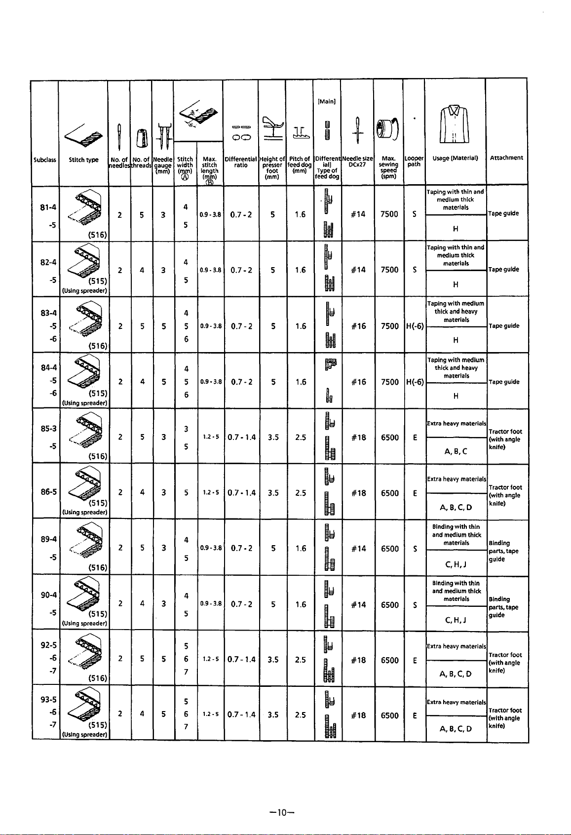
Page 13
<::.,
Subcla$$
Stitch
type
81-4
<~
-5 5
82-4
-5
83-4
-5
-6
84-4
-5
-6 (515)
{516)
~
{515)
(Using spreader)
/~
t.._ • .,.._"·
{516)
~
(Using spreader)
ij
No.
of
reedles
2
2
2 5
2
l]
No.
of
hreads
5 3
4
4
lf
Needle
~auge
mm)
3
5
5
~
@..;
Max.
Stitch
stitch
width
length
('&)
~~
4
0.9-3.8
4
0.9-3.8
5
4
0.9-3.8
5
6
4
0.9-3.8
5
6
==
00
Differential
ratio
0.7-2
0.7-2
0.7-2
0.7-2
~
--
Pitch
of
Height
feed dog
presser
foot
(mm)
5
5
5
5
[Main)
lr
~
Differen
of
(mm) Type
ial)
feed dog
-~
1.6
hi
1.6
1.6
1.6
~
II
+
Needle size Max.
0Cx27
of
#14
~
#14
hi
~
#16
ld
ICB
#16
~
l)j
sewincr
spee
(spm)
7500 s
7500 s
7500
7500
.
Looper
path
H(-6)
H(-6)
m
Usage
(Material)
Taping
with
thin
with
with
with
H
thin
H
medium
H
medium
H
and
and
medium thick
materials
Taping
medium thick
materials
Taping
thick and heavy
materials
Taping
thick and heavy
materials
Attachment
Tape guide
Tape guide
Tape guide
Tape guide
85-3
l~,._
•
.,..
/~
-5
86-5
(516)
2
5 3
4
2
3
~5)
(Using spreader)
89-4
{~
....
<~
-5
90-4
-5
~5)
(Using spreader)
92-5
-6
<~
-7
93-5
-6
~
-7
(Using spreader)
(516)
{516)
{515)
2 5
2 4
2
2
3
3
5
5
4
5
3
1.2-5
5
0.7-1.4
3.5
2.5
~
#18
6500
~
1.2-5
5
0.7-1.4
3.5 2.5
~
#18
6500
~
4
0.9-3.8
5
0.7-2
5
1.6
lw
#14
6500
~
4
0.9-3.8
5
0.7-2
5 1.6
~
#14
6500
~
5
1.2-5
1.2-5
0.7-1.4
0.7-1.4
3.5
3.5 2.5
6
7
5
6
7
2.5
~
#18
~
~
#18
6500 E
6500 E
~
Extra heavy materials
E
A,B,C
Extra heavy materials
E
A,B,C,D
Binding
and medium thick
s
s
materials
C,H,J
Binding
and medium thick
materials
C,H,J
Extra heavy materials
A,B,C,D
Extra heavy materials
A,B,C,D
with
with
thin
thin
Tractor
foot
(with
angle
knife)
Tractor
foot
(with
angle
knife)
Binding
parts. tape
guide
Binding
parts. tape
guide
Tractor
foot
(with
angle
knife)
Tractor
foot
(with
angle
knife)
-10-
Page 14
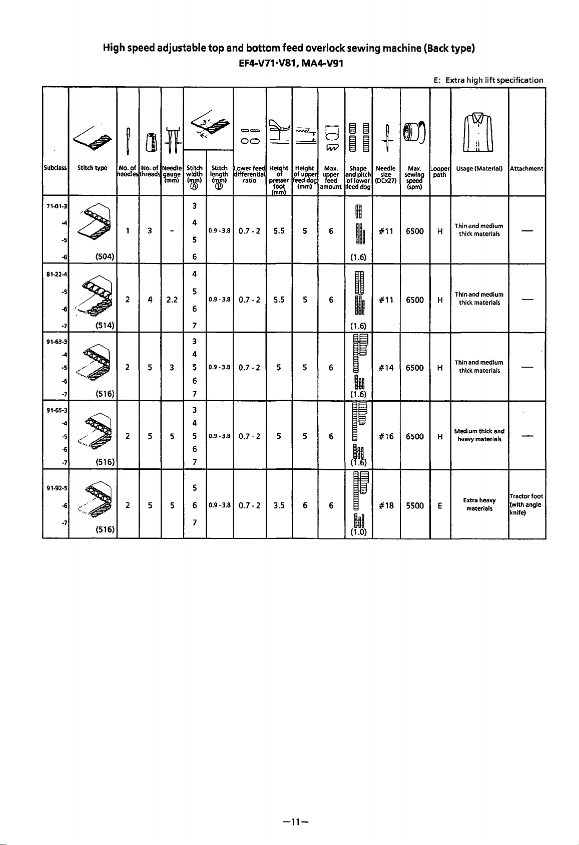
High
speed
adjustable
top
and
bottom
EF4-V71·V81, MA4-V91
feed
Overlock
sewing
machine
(Back
E:
Extra high
type)
lift
specification
<:::,
Subclass
71..01-3
81·22-4 4
91-63·3
91-65·3
Stitch
type
-4
~
·5
-6
·5
-6
-7
-4
·5
·6 6
-7
-4
-5
-6
-7
(504)
-~
:-
........
~.
(514)
1\.•q.
-~
{516)
r.
.•.
/~
{516)
l]
~
No.
of
No. of
hreads
~eedles
1
3
2
4 2.2
2
5
2
5
Stitch Stitch
Needle
*
width
~auge
mm)
-
3 5
5
~
length
('&)
(®)
3
4
0.9-3.8
5
6
5
0.9-3.8
6
7
3
4
0.9-3.8
7
3
4
0.9-3.8
5
6
7
t==
00
Lower feed
differential
ratio
0.7-2
0.7-2
0.7-2
0.7-2
~
~
~
--
Height
He~~ht
ofupJ:r
presser
eed
(mm)
(~~\
5.5
5 6
5.5
5
5 5
5 5
og
a
c;;;:v
Max.
uffe:I
amount
6
6
6
1§1 1§1
i i
Shape
[and
pitch
of
lower
feed dog
H
Ill
{1.6)
H
~
(1.6)
p
hi
(1.6)
p
hi
(1.6)
+
Needle
size
(0Cx27)
#11
#11
#14
#16
l)j
Max.
s;=
(spm)
6500
6500
6500
6500
Looper
path
H
H
H
H
m
Usage
(Material)
Thin and medium
thick materials
Thin and medium
thick materials
Thin and medium
thick materials
Medium thick and
heavy materials
Attachment
-
-
-
-
91-92-5
·6
t ...
/~
-7
2
(516)
5
0.9-3.8
5
6
5
7
0.7-2
3.5 6
6
p
#18
ld
{1.0)
5500 E
Extra heavy
materials
Tractor
(with
knife)
foot
angle
-11-
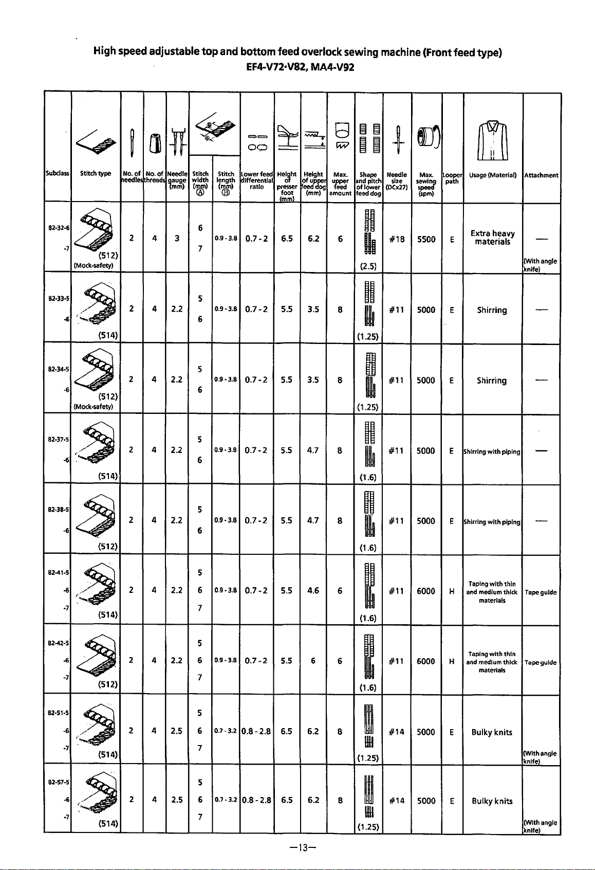
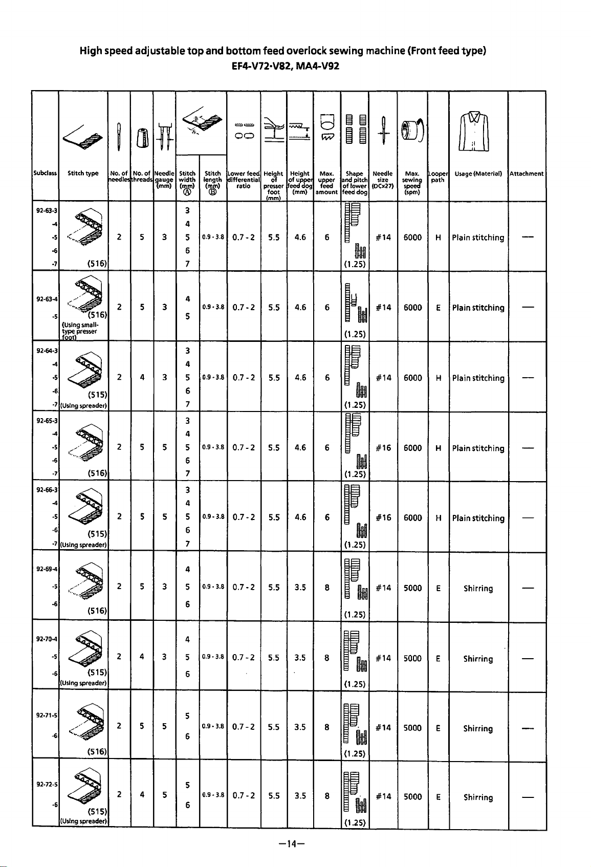
Page 15
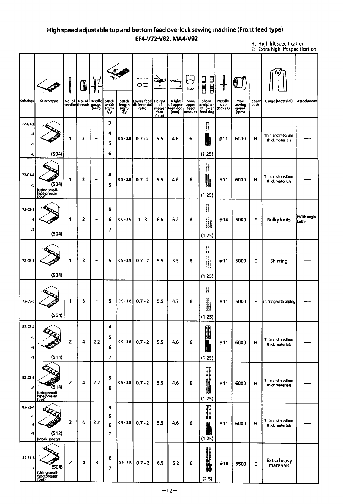
Subclass
72.01·3
-4
·5
·6
High
speed
.::::,
Stitch
type
a
(504)
~
No.
needles hreads
1
adjustable
(l\
of
No.
of
3
top
and
bottom
EF4-V72•V82,
<£;,
®.;
==
00
lf
Needle Stitch Stitch Lower feed
width
~auge
mm)
-
length differential
(roo')
(~)
3
4
0.9-3.8
5
6
ratio presser eed og
0.7-2
feed
overlock
MA4-V92
~
~
==:!:
Height Max.
He~~ht
of
ur3cer
(mm)
(~~\
5.5 4.6
sewing
8
!NV
ureper
eed
amount
machine
~~
iii
Shape
and pitch size
of
lower
feed dog
H
6 #11
~
(1.25)
(Front
em
+
Needle Max.
sew~
(DCx27)
spe
(spm)
6000
feed
H:
High
E:
Extra high
Looper
path
H
type)
lift
specification
lift
specification
m
Usage
(Material) Attachment
Thin and medium
thick materials
-
72.01-4
~4)
·5
(Using small·
%:)presser
72.02·5
·6
a
·1 7
72.08·5
a
{504)
72-09·5
~
82·22-4
·~
1~
'"'-~.
·6
·7
(504)
{504)
(514}
1
1
1 3
1
2
3
-
3
-
-
3
-
4 2.2
4
0.9·3.8
0.6·2.6
0.7-2
1-3
5
5
6
5.5
6.5
4.6
6.2
6 #11
~
(1.25)
n
8
#14
6000
5000 E Bulky knits
Thin and medium
H
thick materials
-
(With angle
knife)
lh
(1.25}
H
0.9·3.8
n
0.9-3.8
0.9-3.8
0.7-2
0.7-2
0.7-2
5.5 3.5
5.5 4.7
5.5 4.6
8
8
6
~
{1.25)
n
~
(1.25)
n ·5
I
(1.25)
#11 5000 E
#11 5000 E
#11
6000
H
Shirring
Shirring
with
piping
Thin and medium
thick materials
-
-
-
5
5
4
5
6
7
82-22·5
.•
~)
·6
(Using small·
%:resser
82·23-4
·5
·6
~
·7
(Mock-safety)
82·31·6
a
·7
(Using small·
%:\presser
{512}
{504)
2 4
2 4
2
5
2.2
2.2
4
3
0.9·3.8
0.9·3.8
0.9
·3.8
0.7-2
0.7-2
0.7-2
6
4
5
6
7
6 n
7
5.5 4.6
5.5 4.6
6.5
6.2
-12-
u-
6
I
(1.25)
n
6
~
{1.25)
6
lh
{2.5)
#11
#11
#18
6000 H
6000
5500 E
Thin and medium
thick materials
Thin and medium
H
thick materials
Extra heavy
materials
-
-
-
Page 16
Subclass
High
speed
<:.,
Stitch
type
needles
adjustable
[]
~
No.
of
No.
of
hreads
top
and
~
~
Needle Stitch Stitch
width
('00')
length
(aD)
1auge
mm)
bottom
EF4-V72•V82,
Lower feed
~Jfferential
c=:.=
00
ratio
feed
overlock
MA4·V92
~
~
~
Height
He~~ht
presser
~~~
(mm)
~~~\
sewing
8
c:;;v
Max.
'feper
eecl
amount
§I §I
B
~
Shape
and pitch
of
lower
feed
dog
machine
I))
+
Needle
size
sew~
(0Cx27)
spe
(Front
Max.
(spm)
feed
type)
rn
Usage (Material)
ooper
path
Attachment
82·32·6
·1
~
(512)
(Mock-safety)
82·33·5
.~
·6
(514)
82·34·5
~
-6
82-37·5
·6
82·38·5
-6
(512)
(Mock-safety)
:~
(514)
~
(512)
2
2 4
2
2
2
4
3
2.2
4 2.2
4 2.2
4
2.2
6
0.9-3.8
7
5
0.9-3.8
6
5
0.9
6
5
0.9·3.8
6
5
0.9-3.8
6
·3.8
0.7-2
0.7-2
0.7-2
0.7-2
0.7-2
6.5
6.2
5.5 3.5
5.5 3.5
5.5 4.7
4.7
5.5
n
6
#18
5500 E
Extra heavy
materials
-
lh
(With
(2.5)
angle
knife)
H
8
#11
5000 E Shirring
-
I
(1.25)
9
8
#11
5000
E
Shirring
-
I
(1.25)
n
8
Ill
(1.6)
#11
5000 E Shirring
with
piping
-
n
8
#11
5000 E Shirring
with
piping
IIi
(1.6)
-
82-41-5
-6
-~
·:...-.,.
·1
82-42·5
·6
~
-7
82·51·5
·6
':·"'--.
~
·1
82·57·5
-6
·:~
·1
(514)
(512)
(514)
(514)
2
2
2
2
4
4 2.2
4
4
2.2
2.5 6
2.5 6
5
0.9
·3.8
6
7
5
6
7
5
7
5
7
0.9·3.8
0.7-3.2
0.7
·3.2
0.7-2
0.7-2
0.8-2.8
0.8-2.8
5.5 4.6
5.5 6
6.5 6.2
6.5 6.2
-13-
6
I
(1.6)
6 #11
I
(1.6)
m
8
1111
(1.25)
w
8
uu
(1.25)
#11
6000 H
6000 H
#14
5000 E Bulky knits
#14
5000 E Bulky knits
Taping
with
and medium
materials
Taping
with
and medium
materials
thin
thick
thin
thick
Tape
guide
Tape
guide
(Wlthangle
knife)
(With
angle
knife)
Page 17
High
<,
speed
adjustable
[]
~
top
~
~
and
bottom
EF4-V72·V82, MA4-V92
==
00
feed
j:
overlock
~
__j_
8
[;WI
sewing
I§
ti
machine
~
i
+
(Front
()j
feed
type)
m
Subclass Stitch
92·63·3
-4
·5
·6
·7
92-63-4
·5
92·64·3
-4
·5
·6
·7 (Using spreader)
92-65·3
-4
·5
·6
·1
92-66-3
-4
·5
-6
-7
type
<.~
(516)
.-~
··~'<..
(516)
(Using small-
I
~~~~\presser
~
(515)
l,
...
,
-~
(516)
~
(515)
(Using spreader)
No.
of
No.
of
hreads
~eedle!
2
5 3
2
5 3
2
4 3
2
5
2
5 5
Needle Stitch Stitch Lower feed
~auge
mm)
5
length
width
(COO')
3
4
5
6
7 (1.25)
4
5
3
4
5
6
7
3
4
5
6
7
3
4
5
6
7
~ifferential
·3.8
·3.8
ratio
0.7-2
0.7-2
0.7-2
0.7-2
0.7-2
(®)
0.9-3.8
0.9
0.9
0.9·3.8
0.9-3.8
Height Max. Shape Needle Max.
Height
of
ofu'fo:
eeclog
presser
(mm)
c~\
4.6
5.5
4.6
5.5
4.6
5.5
4.6
5.5
4.6
5.5
and pitch size
uf:Jr
amount
6
of
lower
feed dog
f
(DCx27)
#14
Ill
6
#14
h~
(1.25)
6
#14
flu
(1.25)
6
f
(1.25)
6
#16
Ill
#16
fld
(1.25)
Usage (Material)
Looper
path
s;~
(spm)
6000 H Plain stitching
6000 E Plain stitching
6000 H Plain stitching
6000 H
6000
Plain stitching
H
Plain stitching
Attachment
-
-
-
-
-
92-69-4
·5
·6
92-70-4
·5
·6
92-71-5
·6
92-72-5
·6
2
2 4
2
2
5
5
4
·\·
....
-~
(516)
:}J
(515)
(Using spreader)
..........
--~
(516)
~
(515)
(Using spreader)
4
0.9.
3
5
3.8
0.7-2
5.5 3.5
8
f~u
6
4
3
5
5
0.9·3.8
5
6
5
0.9.
6
5
0.9-3.8
6
3.8
0.7-2
0.7-2
0.7-2
3.5
5.5
5.5 3.5
5.5 3.5
-14-
(1.25)
8
f~u
(1.25)
8
fid
(1.25)
8
fld
(1.25}
#14
#14
#14
#14
5000 E
5000 E
5000
5000
Shirring
Shirring
E
Shirring
E Shirring
-
-
-
-
Page 18
Subclass
High
<,
Stitch
type
speed
adjustable
[}1
~
No.
of
No.
hreads
reedles
:rr
of
Needle
lauge
mm)
top
and
1f?
Stitch
Stitch
width
length
(®)
(®)
bottom
EF4-V72·V82, MA4·V92
Lower feed
~ifferential
~=
00
ratio
feed
overlock
~
~
===:!:
--
Height
Height
of
ofu':cer
presser
~eed
foot
(mm)
Cmml
og
8
wv
Max.
u~r
amount
sewing
(§
~
~I
Shape
and pitch
of
lower
feed dog
machine
()j
+
Needle
size
(DCx27)
s:=
(Front
Max.
(spm)
feed
Looper
path
type)
m
Usage
(Material)
Attachment
92-75-4
-5
'\·
...
-~
-6
92-76-4
-5
•~...
.....
-~
·6
(Using spreader)
92·77·5
''··~
-~
·6
92-78·5
~
-6
(Using spreader)
92-92-5
(:
·6
..
·~~
·1
..
~
{516)
(516)
(516)
(515)
(516)
2
2 4
2
2 4
2
5 3
3
5 5
5
5 5 6
4
E
E
E -
E
Shirring
(with piping)
Shirring
(with
piping)
Shirring
(with
piping)
Shirring
(with
piping)
Extra heavy
materials
-
-
-
-
Tractor
(with
knife)
foot
angle
0.9-3.8
·3.8
0.9
·3.8
0.9·3.8
0.9
·3.8
0.7-2
0.7-2
0.7-2
0.7-2
0.7-2
5.5
5.5
5.5
5.5
3.5
4.7
4.7
4.7
4.7
5.7
8
#14
5000 E
P~u
(1.25)
8
P~~
(1.25)
8
pld
(1.25)
8
pld
(1.25}
6
~~.~
(2.5)
#14
#14
#14
#21
5000
5000
5000
5500
5
6
4
0.9
5
6
5
6
5
6
5
7
92-93·5
-6
~
·1
(Using spreader)
2 4
(515)
5 6
5
0.9·3.8
0.7-2
7
3.5
-15-
5.7
6
~~
(2.5)
#21
5500 E
Extra heavy
materials
Tractor
(with
knife)
foot
angle
Page 19
c MECHANICAL
[!]
Needle bar
mechanism
DESCRIPTIONS
)
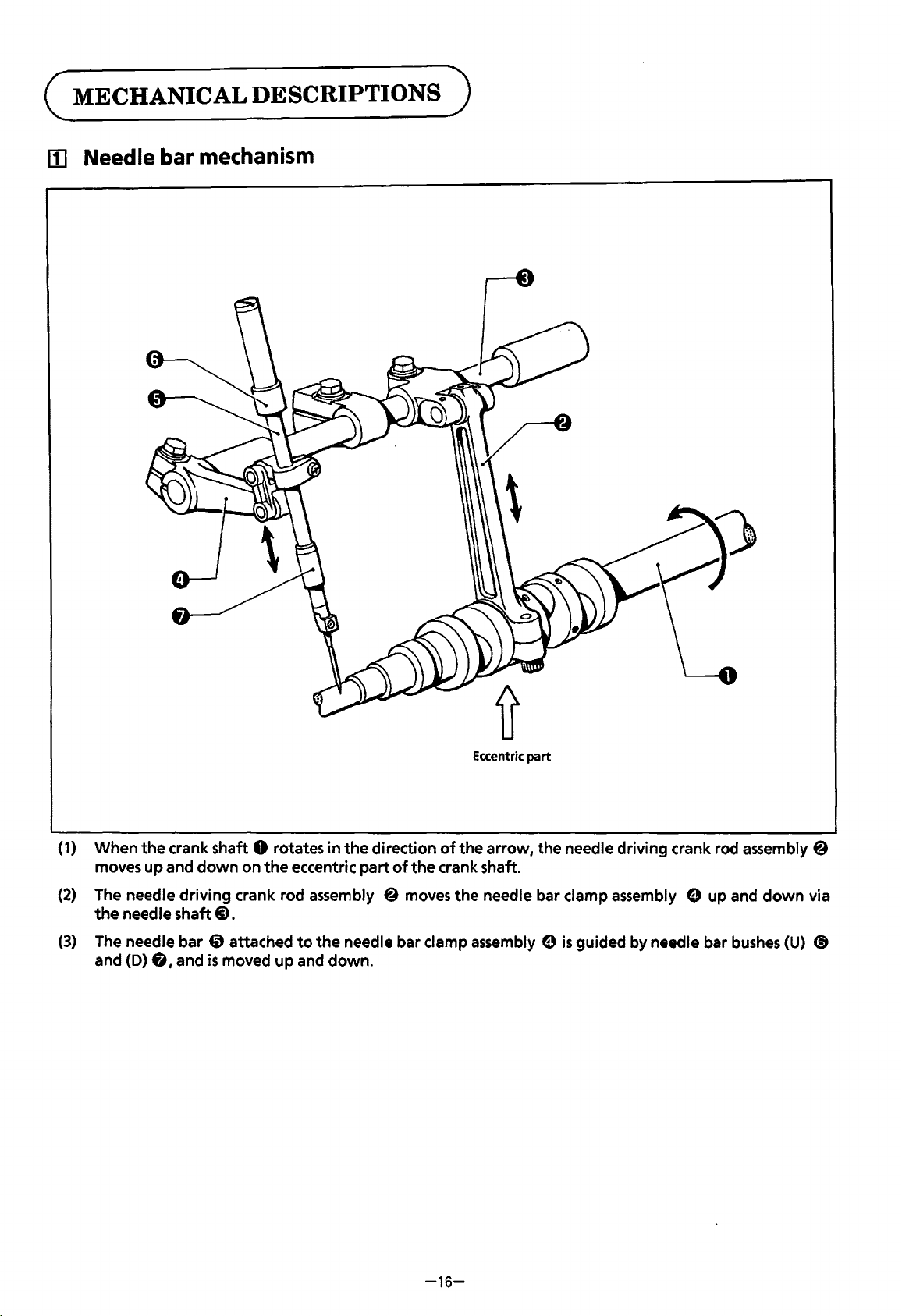
(1) When
moves up and
(2)
The needle
the
needle shaft@).
(3)
The needle bar
and (D)
the
crank shaft 0 rotates
down
on
6,
driving
and
crank rod assembly @ moves
@)
attached
is
moved
the
eccentric
up
to
and
Eccentric
in
the
direction
part
of
the
needle bar clamp assembly e
down.
of
the
crank shaft.
the
the
arrow,
needle bar clamp assembly e up and
part
the
needle driving crank rod assembly @
is
guided by needle bar bushes (U)
down
via
<9
-16-
Page 20
[2]
Under looper
mechanism
Eccentric
part
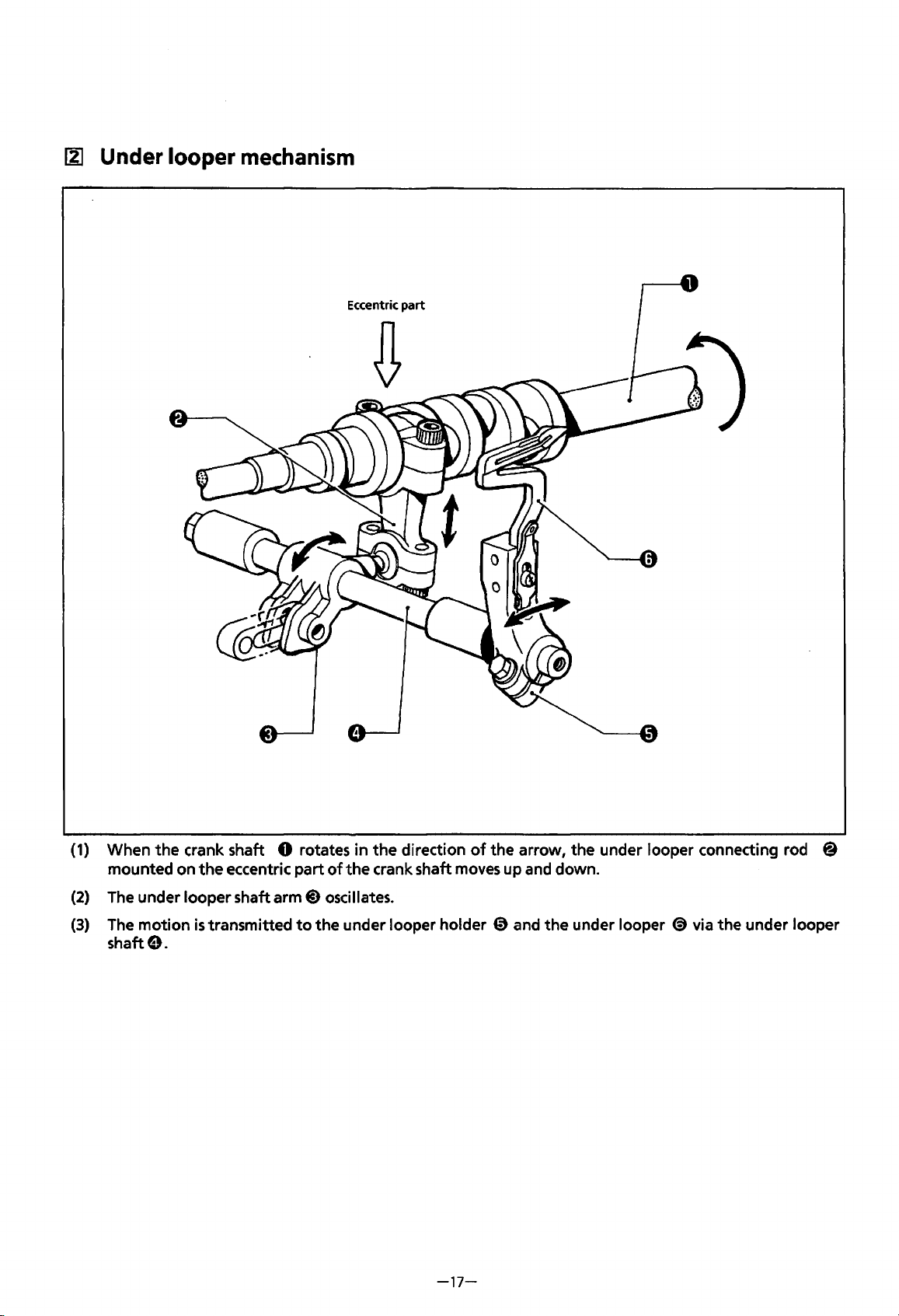
(1)
When
(2)
(3)
the
crank shaft 0 rotates in
mounted on
The
under looper shaft
The
motion
shaft e.
the
is
eccentric part
arm@)
transmitted
the
direction
of
the
crank shaft
oscillates.
to
the under looper holder 0 and
moves
-17-
of
the arrow, the under looper connecting rod @
up and down.
the
under looper
@}
via the under looper
Page 21
~
Over looper mechanism
(
Eccentric
~
part
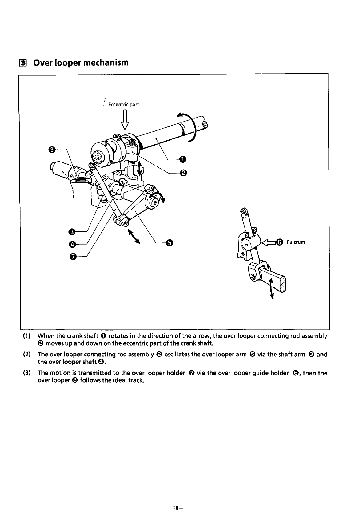
(1)
When the crank shaft 0 rotates in the direction
@ moves up and down on
(2)
The
over looper connecting rod assembly @ oscillates the over looper arm 0 via the shaft arm
the
over looper shaft
(3)
The motion
over looper@) follows
is
transmitted
0.
the
the
eccentric part
to
the over looper holder 6 via
ideal track.
of
of
the arrow, the over looper connecting rod assembly
the
crank shaft.
the
over looper guide holder
-18-
@,
@)
then
and
the
Page 22
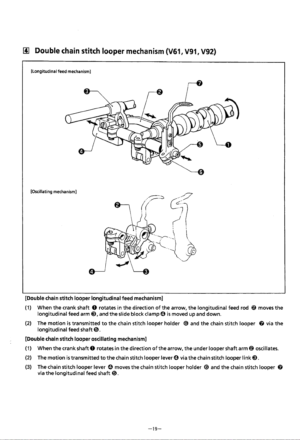
[!]
Double
[Longitudinal feed mechanism]
[Oscillating mechanism]
chain
stitch
looper
mechanism
(V61,
V91,
V92)
[Double chain stitch looper longitudinal feed mechanism]
{1)
When
longitudinal feed
{2)
The motion
longitudinal feed shaft@).
[Double chain stitch looper oscillating mechanism]
(1)
When the crank shaft 0 rotates in the direction
{2)
The
(3)
The chain stitch looper lever 0 moves the chain stitch looper holder @)and the chain stitch looper &
via
the
crank shaft 0 rotates in
arm@), and the slide block clamp 0
is
transmitted
motion
the
is
transmitted
longitudinal feed shaft@).
the
direction
to
the chain stitch looper holder
to
the chain stitch looper lever 0 via the chain stitch looper link@).
of
the arrow, the longitudinal feed rod @ moves the
is
moved up and down.
@)
of
the arrow, the under looper shaft arm@ oscillates.
-19-
and
the chain stitch looper & via
the
Page 23
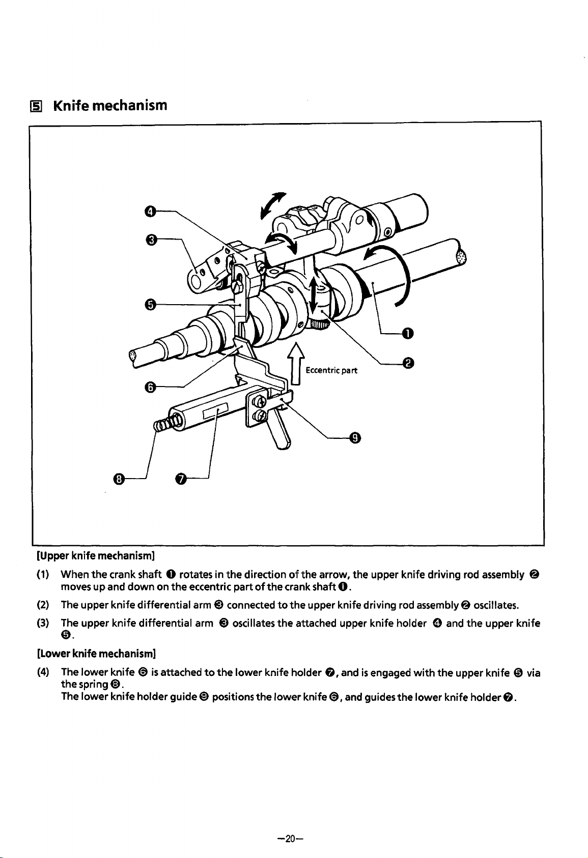
[51
Knife
mechanism
[Upper knife mechanism]
(1)
When
the
crank shaft 0 rotates in
moves up and
(2)
The upper knife differential
(3)
The upper knife differential arm
down
on
the
eccentric part
arm@)
the
direction
connected
@)
oscillates
of
the
of
the arrow,
crank shaft
to
the
upper knife driving rod assembly 8 oscillates.
the
attached upper knife holder 9 and
the
0.
@).
[Lower knife mechanism]
(4)
The
lower
knife
(9
is
the
The
spring
lower
attached
@).
knife holder guide@) positions
to
the
lower
the
knife holder
lower
knife
-20-
6,
and
is
<a,
and guides the lower knife holder
upper knife driving rod assembly @
the
upper knife
engaged
with
the
upper knife 0 via
6.
Page 24
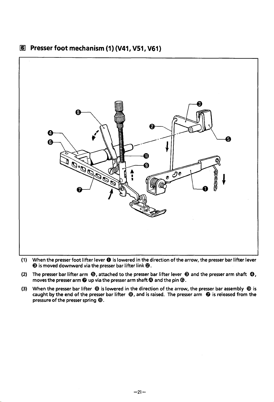
[§]
Presser
foot
mechanism (1) (V41, V51, V61)
(1) When
(2) The presser bar
(3) When
the
presser
@}is moved
moves
caught by
pressure
the
the
of
foot
downward
lifter
presser arm
presser bar
the
end
of
the
presser spring
lifter
via
the
arm
0,
fi
up
lifter
the
presser bar
lever 0
presser bar
attached
via
the
@)
is
lowered in
en>.
is
lowered
to
presser arm shaft e and
lifter
in
lifter
link@.
the
presser bar
the
@),
and
-21-
the
direction
lifter
direction
is
raised. The presser arm
of
the
the
of
lever
pin(!).
the
arrow,
@)
arrow,
the
presser bar
and
the
presser arm shaft
the
presser bar assembly
fi
is
released
lifter
from
lever
9,
@)
is
the
Page 25
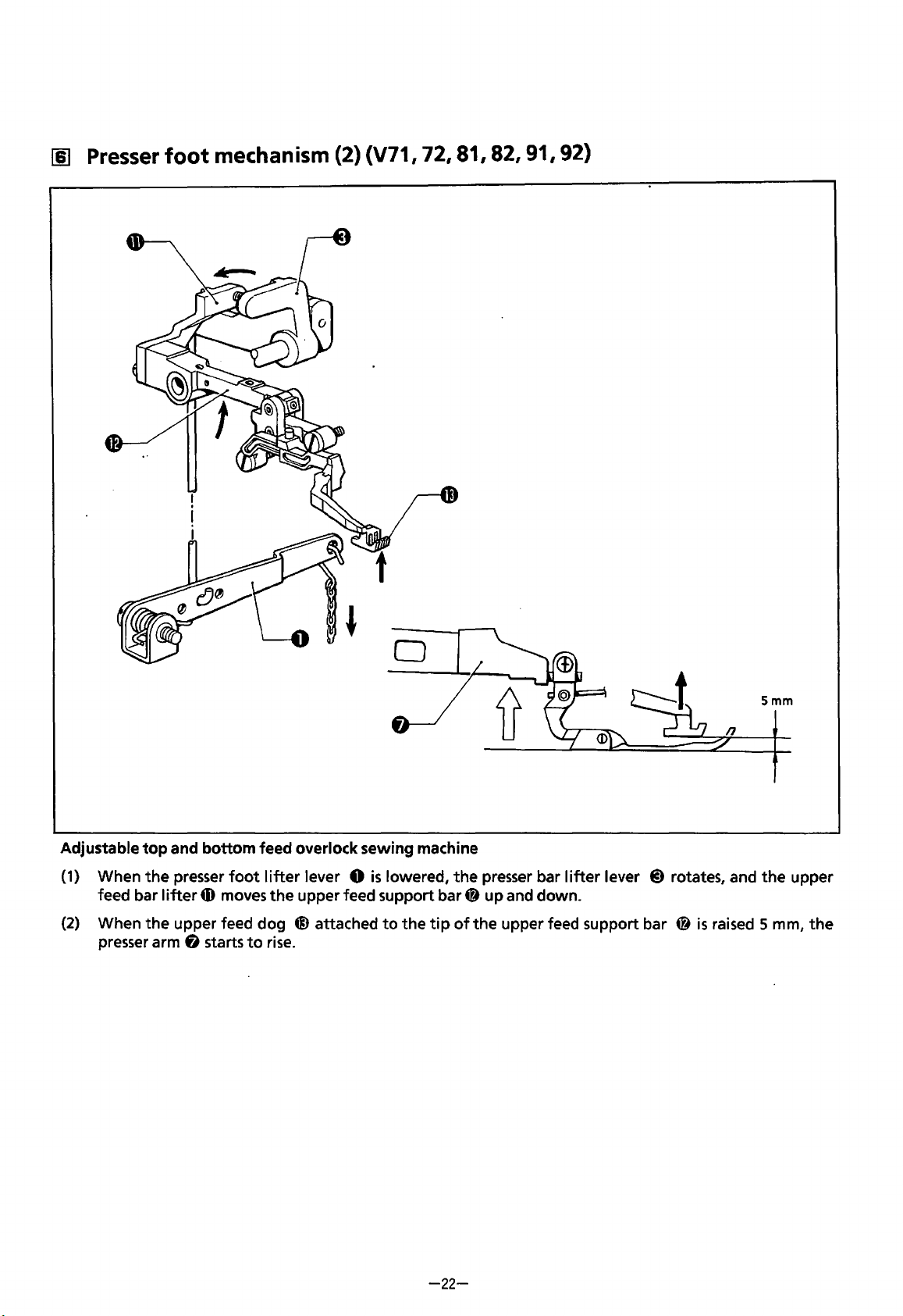
[I) Presser
foot
mechanism (2) (V71, 72, 81, 82, 91, 92)
Adjustable
(1)
(2)
top
When
the
feed bar
When
the
presser arm & starts
and
bottom
presser
lifter
upper feed dog
foot
m moves
to
feed overlock sewing machine
lifter
lever 0
the
upper feed support bar
@attached
rise.
is
lowered, the presser bar
4)
to
the
tip
of
lifter
lever
@)
rotates, and
up and down.
the upper feed support bar @
Smm
the
is
raised 5 mm,
upper
the
-22-
Page 26
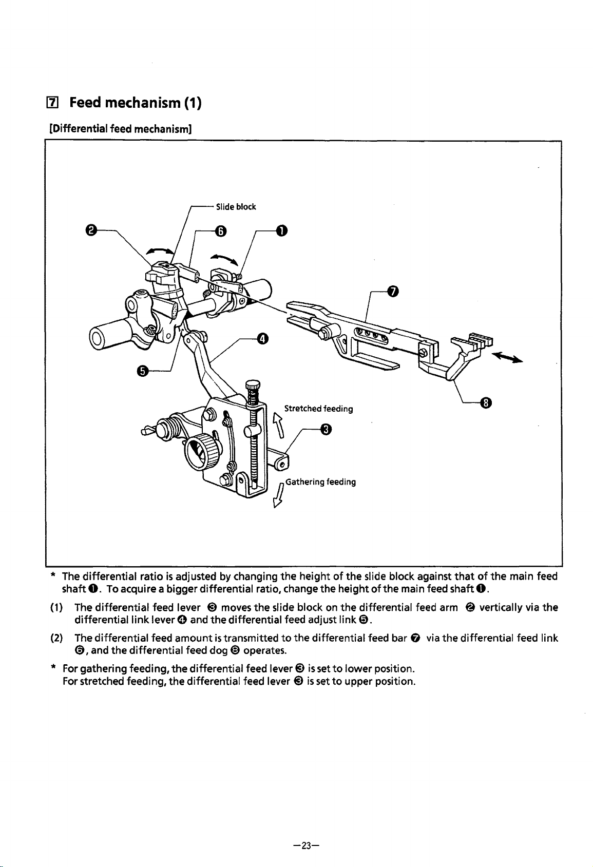
111
Feed
[Differential feed mechanism]
mechanism
(1)
Slide
block
* The
(1) The
(2)
differential
shaft
0.
differential
differential
The
differential
@),
and
ratio
To acquire a bigger
feed lever
link
lever e and
feed
the
differential
* For gathering feeding,
For stretched feeding,
is
adjusted by changing
differential
@)
moves
the
differential
amount
the
the
is
transmitted
feed dog
differential
differential
@)
operates.
feed lever@)
feed lever
JGathering
the
height
ratio, change
the
slide block on
feed adjust
to
the
@)
feeding
of
the
slide block against
the
height
the
link@.
differential feed bar
is
set
to
is
set
to
of
the
differential feed arm @ vertically via
lower
position.
upper position.
that
main feed shaft
fi
via
the
differential feed
of
0.
the
main feed
the
link
-23-
Page 27
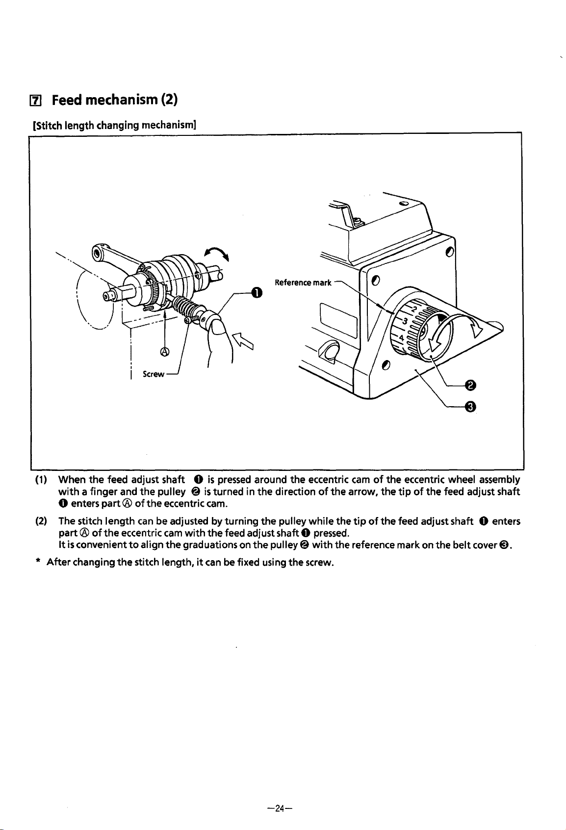
111
Feed
mechanism
(2)
[Stitch length changing mechanism]
(1) When
with
a finger and
0 enters
(2)
The stitch length
part®
It
is
convenient
*
After
changing
the
feed adjust shaft 0
the
pulley @
part®
of
the
of
the
can
eccentric
to
align
the
stitch length,
be adjusted by turning
is
pressed
is
turned in
eccentric cam.
cam
with
the
the
graduations on
it
can
Reference
around the eccentric
the
direction
the
pulley
feed adjust shaft 0
the
pulley@
be fixed using
the
mark
cam
of
the eccentric wheel assembly
of
the
arrow,
while
the
pressed.
with
the reference mark on the
screw.
tip
of
the
the
tip
of
the
feed adjust shaft
feed adjust shaft 0 enters
belt
cover@).
-24-
Page 28
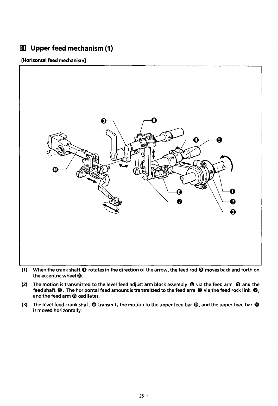
1!1
Upper feed
[Horizontal feed mechanism]
mechanism
(1)
(1)
When
the
crank shaft 0 rotates in
the
eccentric wheel
(2)
The
motion
feed shaft
and
the
(3)
The level feed crank shaft
is
moved horizontally.
is
0.
feed
transmitted
arm@
@.
to
The horizontal feed
oscillates.
@)
the
direction
the
level feed adjust arm block assembly
amount
transmits
the
of
the
is
transmitted
motion
to
-25-
arrow, the feed rod
to
the upper feed bar
the
@)
moves back and
(9
via the feed arm e and
feed arm @ via
G!>,
and
the
feed rock I
the
upper feed bar
forth
ink
on
the
fj,
G!>
Page 29
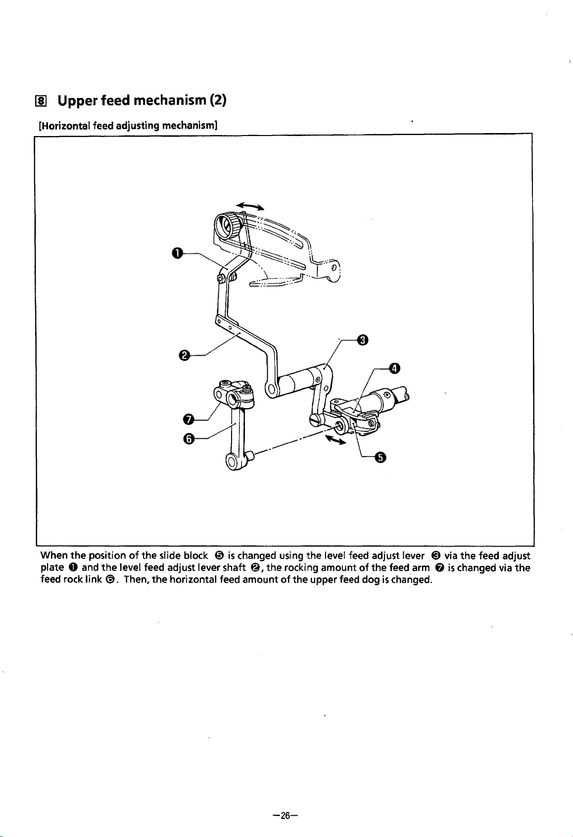
[I]
Upper feed mechanism (2)
[Horizontal feed adjusting mechanism]
the
When
plate
0 and
feed rock
position
link@.
of
the
slide block 0
the
level feed adjust lever shaft
Then,
the
horizontal feed amount
is
changed using
@,the
-26-
the
level feed adjust lever
rocking amount
of
the
upper feed dog
of
the
feed arm 6
is
changed.
@)
via
is
the
feed adjust
changed via
the
Page 30
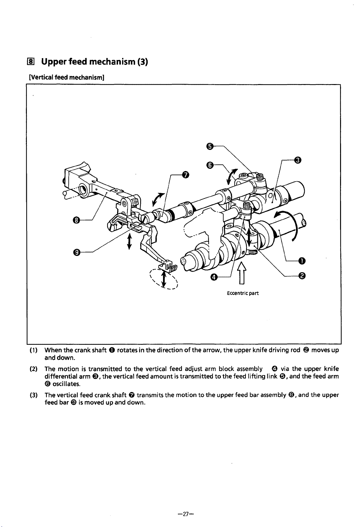
00
Upper feed mechanism {3)
[Vertical feed mechanism]
(1)
When
and down.
(2)
The
differential
<9
(3)
The
feed
the
crank shaft 0 rotates in
motion
osci
vertical feed crank shaft G transmits the motion
bar@)
II
ates.
is
transmitted
arm@) I
is
the
moved up and down.
to
vertical feed amount
the
direction
the vertical feed adjust arm block assembly 0 via the upper knife
of
is
transmitted
Eccentric
the arrow, the upper knife driving rod @ moves up
to
the feed
to
the upper feed bar assembly @),and
part
lifting
link@) I and
the
the
feed arm
upper
-27-
Page 31

[I]
Upper feed
[Vertical feed adjusting mechanism]
mechanism
{4)
the
(UL)
position
0,
When
shaft
horizontal feed
of
the
rocking
amount
the
slide block 0
amount
of
the
is
changed using
of
the
feed arm (§}is changed via
upper feed dog
is
changed.
the
vertical feed adjust lever @ via adjust lever
the
feed
lifting
link
0.
Then,
the
-28-
Page 32

[II
Lubrication
-29-
Page 33

c
DISASSEMBLY)
[II Covers
NOTE:
Drain
the
oil
from
the
pump by
turning
the
pulley a
I
®
I
few
times before
remo-ooing
--~
the
cover.
(
1)
Remove
(2)
Remove
(3)
Remove
(4)
Loosen
(5)
Remove
(6)
Loosen
(7)
Remove
(8)
Remove
(9)
Remove
(1
0)
Remove
(11) Remove
(12)
Remove
(13) Remove
(14) Remove
the
three screws and
the
four
bolts and
the
four
screws and
the
two
screws, and remove
the
presser arm assembly 0 from
the
set screw, and remove
the
two
screws, and
the
two
screws and
the
six screws,
the
two
screws, and
the
four
screws, and
the
two
screws, and
the
three
screws, and
the
six screws,
the
the
the
the
the
the
feed bar cover@), and
the
the
the
the
the
cover
belt
cover
0.
oi I reservoir@.
top
cover@).
the
face plate cover e by sliding
the
needle plate.
the
cloth plate along
cloth guide
cloth guide set plate@).
eccentric wheel cover
frame side cover G).
front
front
for
feed mechanism
cover
cover
6.
the
(L)
guide~.
(L)
assembly@) by sliding
-30-
with
the
packing.
4Il>.
(B)
4D,
and
cloth plate (lower)@).
the
it
to
the
it
to
the
packing.
front.
front.
Page 34

~
Presser
foot
mechanism
(V61
(V711
I
V91
V721
I V92)
V81
V821 V91
1
1
V92)
(
1)
(2)
Loosen
Remove
the
screw, and remove
the
screw, and
the
the
upper feed dog
presser
foot
0.
@.
(This
step
is
for
overlock sewing machine.)
(3)
Loosen
(4)
Remove
remove the presser bar
(5)
Remove
(6)
Remove
the
bolt
for
the
presser bar I
the stud screw, and
lifter
the
two
screws, and
the
screws, the thread guide pipe G, and the looper thread guide
ifter
arm
the
presser bar
lever@).
the
lever adjust plate@.
@),
and remove the
lifter
link from the
sewing machine only).
-31-
only adjustable
presser
arm shaft·
presser
foot
top
and bottom feed
0.
lifter
lever
€l
(for
the safety stitch
@).
Then,
Page 35

~
Knife
mechanism
(1)
(2)
(3)
(4)
Remove
Remove
Remove
Loosen
the
screw and
the
screw,
the
bolt, the lower
the
screw, and remove
the
the
upper knife
upper knife holder@, and the nut.
knife@
the
0.
I and the
lower knife holder (D and
lower
-32-
knife
presser
the
e.
spring
@).
Page 36

III Under looper
mechanism
(1)
Loosen
(2) Remove
(3)
Remove
(4) Remove
(5)
Loosen
from
the
(6)
Remove
the
set screws
the
two
the
screw, under looper thread guide
the
screw and looper thread take-up
the
screw
under looper shaft & .
the
movable needle guard from
of
the
screws and
of
the
movable needle guard, and
needle clamp
the
needle plate@).
0,
and remove
(L)
e I and
(L)
<9.
the
under looper holder@).
the
the
the
bolt, and remove
needles@.
under looper
0.
the
under looper holder
@)
-33-
Page 37

~
Over
looper
mechanism
(1)
Remove
(2)
Loosen
looper
(3)
Remove
(4)
Loosen
(5)
(6)
Remove
NOTE:
Loosen
the
three screws and the thread guide bracket
the
screw, and remove over looper thread take-up
thread take-up
the
five screws,
the
screw, and remove
the
bolt
for
the
two
The guide bush positioning plate
unless
it
is
necessary.
(R) 0 will
the
the
over looper arm
screws,
the
come off.)
inside cover@), and
the
over looper@) from
over looper mechanism assembly
{I)
0.
(R)
@)
from
the
looper thread guide
the
over looper holder & .
@).
4Ii>
from
has
already been adjusted before shipping.
-34-
the
over looper shaft @. (Under
(9.
the
over looper shaft@.
Do
not
remove
it
Page 38

(§]
Double
chain
stitch
looper
mechanism
(V61,
V91,
V92)
(1)
(2)
(3)
(4)
(5)
(6)
(7)
Remove
Remove
Remove
Remove
(F)@).
Loosen
Remove
Loosen
the
bolt,
the
main feed dog
the
screw,
the
screw and
the
screw, chain stitch needle guard
the
bolt, and remove the chain stitch looper holder 0 from the longitudinal feed shaft@).
the
stud screw and the thread handler
the
two
set
the
chain stitch looper@ from the chain stitch looper holder
the
felt
screws,
and remove the thread take-up assembly
0,
and the differential feed
support assembly@.
(B)
@,needle guard
bracket~.
-35-
dog@.
(F)
6,
tD.
e.
and chain stitch needle guard
Page 39

11]
Needle
bar
mechanism
(1)
Remove
(2)
Loosen
(3)
Remove
(4)
Remove
lifting
(5) Loosen
needle bar clamp assembly
the
needle
the
set screw, and remove
the
screw 0
the
oil cap
it
from above.
the
bolts
bar@
<9,
for
by
turning
the
of
needle bar bush (U)
and loosen
the
needle balance
4D
along
the
needle clamp 0 in the direction
needle thread holder@) from the needle
9.
the
screw
of
@)
and
with
the needle shaft
the needle bar clamp
the
needle driving crank rod assembly
4D).
fj.
of
the arrow.
bar@.
Remove
the
needle bar @ by
@).
Remove
the
-36-
Page 40

[II
Feed
mechanism
I
)
®'
~
(1)
Loosen
(2)
Remove
(3)
Tilt
of
(4)
Return
machine head, and
(5)
Remove
only).
(6)
Loosen
(7)
Tilt
shafteD.
*
the
set screw
the
two
the
machine head until
the
set collar@.
the
machine head
the
two
the
bolts
the
machine head until
After
the
feed shaft
0,
and remove the set screw knob@.
bolts, and
Remove
the
oil
screws
for
and the longitudinal feed arm stopper@) (for the safety stitch sewing machine
the
feed arm assembly
CD
the
differential stitch control plate@).
it
stops.
the differential feed adjust lever(!).
to
cap@}
it
is
removed, return the machine head
Loosen
its original position.
on the machine side.
stops.
4!0,
Loosen
the
the
-37-
bolt
the
set
of
the differential link lever
Remove
differential feed arm
screw
of
the oil
the set collar
to
cap
& on the rear side
4D,
and
its original position.
e,
and
the
main feed arm
@,
and
the
set
screws
of
the
4).
remove the feed
Page 41

[I] Upper feed mechanism (1)
[Horizontal feed]
~
-~
"'
---"', .
Jf!f:::r~d~r
Stud screw J assembly
(
1)
Remove
(2)
Loosen
(3)
Remove
(4)
Remove the
(5)
Loosen
(6)
Remove
(7)
Loosen
the
Remove
the
the
set screw
the
the
set screw, and remove upper feed bar guide
the
the
feed arm
the
spring
two
two
stud screw
set screws
level
0.
screws and
screws and
@).
fee~
knob@,
the
the
of
the
for
the
crank shaft
and remove the set
level feed length control plate@).
feed adjust plate e from
level feed crank shaft@). (The upper feed bar assembly
two
set collars attached
@).
screw@)
(L)
to
from
the
feed adjust plate
the
level feed adjust lever shaft@).
6.
the
level feed crank shaft @),and
e.
will
come
the
off.)
bolt
of
-38-
Page 42

[j] Upper feed mechanism (2)
[Vertical feed]
(
1)
Loosen
(2)
Remove
(3)
Loosen
vertical feed adjust lever(!). Remove adjust lever shaft
(4)
Loosen
(5)
Remove
{6)
Loosen
the
set screw
the
two
the
set screw
the
adjust screw
the
screw and silicone
the
set screw, and remove upper feed bar guide
0,
and remove
screws and
for
the
6,
the
set screw
the
vertical feed length control plate@.
set collar 0 attached
and remove
tank
it
along
assembly
with
(U)
knob@.
to
(U
the
~.
Setscrew
adjust lever shaft
L)
0.
spring.
(R)@).
(U
L)
0,
and the
bolt
of
the
-39-
Page 43

[I)
Upper
[Vertical feed]
feed
mechanism
(3)
(7) Loosen
vertical feed crank shaft
(8) Remove
the
(9)
Remove
the
set screws
the
upper feed bar assembly
upper feed bar assembly.)
the
vertical feed crank shaft
of
the
0.
set coli
ars
@from
0.
4n>,
and
o
____
Set
collars
0
the
bolt
of
the
feed arm
the
presser arm shaft bush
____
_
4D.
Remove
tD.
(The
o
0
the
wick
screw
is
attached
of
the
to
-40-
Page 44

(ASSEMBLY)
1I1
Upper feed mechanism (1)
[Vertical feed]
0-----...
6 m m ---+--+--•
0
____
o
0
(1)
(2)
(3)
Pass
the
the
set collar @
surface.)
Attach
Secure
the
the
vertical feed crank shaft 0 through
so
that
the
end
of
the
vertical feed crank shaft 0 protrudes 6 mm from
upper feed bar assembly 0 along
vertical feed crank shaft 0 using
Set
collars
the
frame. (Position
with
the
wick
the
screw.
the
vertical feed crank shaft 0 using
to
the presser arm shaft bush
9.
the
frame
-41-
Page 45

[i] Upper feed
[Vertical feed]
mechanism
(2)
r
(4)
Pass
adjust lever shaft
bolt
of
{5) Secure
(6) Attach
(7) Insert
the
vertical feed adjust lever@).
the
vertical feed length control plate@) using
the
set screw knob
the
spring
4»
(U
into
L)
(i)
Q)
to
the
frame, and
through
adjust lever shaft
the
frame, and
tighten
tighten
the
(UL)
(i) using
the
adjust screw@.
-42-
the
screw.
the
set screw
set screw
of
the
set collar & and
4ID.
the
Page 46

[!]
Upper feed
[Horizontal feed]
mechanism
(3)
0
(1)
Insert
the
level feed crank shaft 0
collar @
tighten
(2) Insert
(3)
Secure upper feed bar guide
backward
feed bar assembly
so
that
the
the
set screw and
the
upper feed bar assembly 0
or
forward, and position upper feed bar guide
end
e.)
into
the
frame. (Position the level feed crank shaft 0 using
of
the
level feed crank shaft 0 protrudes
the
bolt
of
the feed arm 8
into
(R)
0 using
the
the
.)
level feed crank shaft
set screw. (Move
Silicone tank
(R)
assembly
7.5
0,
the
0
so
(U)
mm
from
the
frame edge. Then
and
tighten
upper feed bar assembly 0
that
it
does
the
stud screw.
not
touch
the
the
set
upper
{4)
Attach silicone
{5)
Attach upper feed bar guide
{6)
{7)
Attach
Attach
the
the
tank
assembly
{L) ~ using
feed adjust plate@)
upper feed dog@)
{U)
to
to
using
the
screw.
the
set screw.
the
level feed adjust lever shaft & using
the
upper feed bar assembly e using
-43-
the
the
screw.
screw.
Page 47

[!]
Upper feed mechanism (4)
[Horizontal feed]
(8)
Attach
(9}
Attach
(10) Attach
the
level feed length control plate
the
set screw knob 4i
the
spring@.
to
the
CD>
using
the
screw.
feed adjust plate@) using
the
set screw
tD.
-44-
Page 48

~
Feed mechanism (1)
©
{1)
Tilt
the
machine head until
the
differential feed arm
stitch sewing machine,
(Insert
block,
. (2) Position
inside face
the
and place them on
the
shaft
of
the
feed shaft 0 using
of
the
bush.)
it
stops.
8,
the
the
longitudinal feed arm(§) should
differential feed
the
differential feed arm 8
Pass
the feed shaft 0 through
main feed arm
link 6 into
the
set collar @
e,
-45-
so
and
the
set collar 0 in
be·
the
differential feed adjust
.)
that
the
the
bush,
also inserted.)
end
of
the feed shaft 0
the
feed arm assembly@,
that
order. (For
link
@)
is
the
and
flush
safety
the
with
slide
the
Page 49

~
Feed
mechanism
(2)
(3)
Set
the
stitch length
reference mark
retracted.
NOTE:
(4)
Pass
$,and
set screw
(S)
Attach the longitudinal feed arm stopper@ using the
(6)
Attach
(7)
Attach the set screw knob
When tightening
on both
the
differential feed adjust lever @)through the
remove any
of
the
the
differential stitch control plate
to
the maximum. Tighten the bolt
of
the feed shaft 0
the
bolt
sides.
looseness
set
collar®.
trP
on the
(Hang
to
is
of
the feed arm @,make
left
and right
the
spring ~ .)
the differential feed adjust lever@) using the set screw@.
on the
6)
top
of
using the bolt.
I
)
~
~
of
the feed arm assembly @
when the feed arm
sure
that
bush,
set collar
the differential feed adjust lever, and tighten the
screw.
(Only
for
no
looseness
®,and
V61,
assembly
of
the differential link lever
V91,
V92.)
so
that
the
@
is
extremely
the feed arm @
·
is
-46-
Page 50

~
Feed
mechanism
(3)
Slide block
Approx.6mm
Main feed bar
Differential feed bar
(Lower
the
(Raise
the
differential link lever.)
differential link lever.)
•
~
[Adjusting
{1)
(2)
(3)
[Adjusting the feed
* Before this adjustment, set
(1) Temporarily tighten
(2)
the
standard feeding position
Set
the
stitch length
extreme back.
Temporarily
Loosen
that
it
tighten
the
set screw knob
stops by moving
of
the main feed bar and
positioned 6 mm above
aligned
Align
the
lever @ up
the
with
the
maximum setting.
the
differential feed adjust lever @)to the upper third reference line (for plain stitching). Adjust
timing
between
or
down
farthest forward position.
To
the
farthest forward position
of
the differential feed arm]
to
the
maximum, and
the
bolts
for
the
differential link lever
@.
Adjust the back and forth inclination
the
differential feed adjust lever@).
the
movement
the
differential link lever
the
differential feed arm
the
main feed bar and
so
that
the
main feed bar
turn
the
differential feed bar]
of
the main feed dog
-........
the pulley
to
C@
Then
C@
until
the
slide block
@)
when the differential feed adjust lever
the
differential feed bar by moving
is
even
with
the differential feed bar when they move
-47-
To
the
farthest
set
the differential feed arm
and
the differential feed arm@).
forward
of
the differential feed arm
position
tighten the bolts again.
to
3.8 mm.
of
the differential feed arm
the
@)
to
differential
the
@)so
@)
is
@)
is
link
to
Page 51

~
Needle
bar
mechanism
(1)
Screw~
Frame
top
(1)
Insert
the
needle shaft 0
balance
ofthethrust.
(2)
Insert
and
(3)
Attach
(4) Turn
the
the
NOTE:
(5)
Tighten
bar
{6)
Temporarily attach the main feed dog
@)
and the needle driving crank rod assembly e
the
needle bar 0
the
needle bar clamp & , and attach
the
screw
of
the
pulley
to
set
needle driving crank rod e
bush.
Make sure
the
is
at
its lowest position.
bolt
that
of
with
into
needle bar
the
needle driving crank rod 0
the
the needle balance
the needle bar clamp assembly @ into the
so
that
·
needle bar
bush
so
pulley turns easily.
bush
(U)
~-
Pass
the
needle clamp@).
(U)
~.
that
the needle bar clamp &
@)
so
that
it
aligns
4ID,
the differential feed dog
them through the needle thread holder @
to
its highest position, then tighten
with
the
bush,
and attach
there
is
no
looseness
is
positioned 3
top
of
tD,
and the needle plate C).
mm
the frame when
in
the
under
the
needle
direction
the
bolt
the
end
the
needle
of
of
-48-
Page 52

~
Needle
bar
mechanism
(2)
(7) Loosen
into
the
screw
the
needle hole on
of
the
needle bar clamp assembly
the
* For a single-needle machine,
*
For
a twin-needle
H
(8)
Turn
the
clearance between
pulley
or
safety stitch sewing machine,
H
to
move
the
needle
needle plate.
turn
the
the
needle bar 0
tip
needle
and
the
6.
Turn
bar@)
H
to
face surface A
turn
the
needle
Dimension H
V411
V611
V71
V721 V911 V92
VS1 I V81
to
its highest position. Refer
I V82
needle plate top, and
the
pulley slowly
of
the
screw
bar@)
to
find
S {Standard) H (High
10±0.2
mm
10.9±0.2
11.4±0.2
~
to
the
fix
it.
to
insert
the
needle
toward
n·eedle
the
front.
locati~n.
lift)
E (Extra
mm
12±0.2
mm
12±0.2
above table, adjust
high
mm
mm
tip
lift)
the
(9)
Remove
the
needle@,
the
needle plate
4D,
the
main feed dog Q), and
-49-
the
differential feed dog
CD.
Page 53

[II
Under
looper
mechanism (1)
(1)
Attach the under looper @
(L)
thread guide
using the
looper holder
using the bolt.
NOTE:
The
so
under looper holder
@)
screw.
Temporarily attach
0
under looper @ should be attached
that its bottom sticks
and
under looper
to
the under looper holder 0
the
to
the under looper shaft e
to
the pin
0.
under
of
the
0-0.0Smm
overlap
------'
[Adjusting the farthest
looper]
<D
Turn the pulley
to
way
®
Loosen
0
the center
point.
®
Raise
the under looper
looper
when the under looper @ point aligns
center
the left.
the bolt. Move the under looper holder
so
that
there
of
the needle
the needle from its lowest position. Adjust
@ point overlaps the needle
of
the needle.
left
position
to
move the under looper all the
is a 3.8
holder 0
mm
and
of
the
under
clearance between
the under looper
so
that
the under
0-
0.05
mm
with
the
-50-
Page 54

[!]
Under looper
mechanism
0-0.05
mm
{2)
[Adjusting the movable needle guard]
<D
Attach the movable needle guard
looper holder
®
Raise
the needle from its lowest position
the under looper
needle.
® Loosen
movable needle guard
there
is
needle and the under looper
0 using the bolt.
@point
the
bolt. Adjust
a 0 - 0.05
with
the
@)
by moving
mm
clearance between
@.
@)
to
the
center
position
the under
to
align
of
the
of
the
it
so
that
the
[Adjusting needle guard
<D
Attach needle guard
support bracket using the screw
®
Raise
the needle from its lowest position
the under looper
needle. Adjust the position
so
that
the
clear.ance
and the needle
with
a thread number over and including
(thin thread); approx.
(thick thread).
(F)]
@point
is
0.05-
(F)
(§)
to
the needle plate
f).
to
with
the center
of
needle guard
between needle guard
0.2
mm
for
using threads
0.3
mm
using #30 thread
align
of
the
(F)
(F)
#50
(§)
(§)
-51-
Page 55

~
Over looper
mechanism
_..,....~-A
(1)
~
A
S (Standard)
1.6±0.2 0
Touch
H (High
the
lift)
right
side.
E (Extra high
1 ±0.2
lift)
(1) Insert
screw
@).
NOTE:
(2)
Attach
Adjust
(S
(standard) = 1.6 ± 0.2, H (high
the
over looper mechanism assembly 0
so
that
the
over looper guide holder touches the
Make sure
assembly.
the
over looper e
the
clearance between the over looper 0 and the over looper holder@
that
the
over looper holder
to
the
over looper holder@ using
lift) = 0,
into
the over looper
@)
E (extra high
(3) ~ Turn
under
without
position
tighten the screw.
shaft@,
right
side
of
moves smoothly in the over looper mechanism
the
screw.
lift)
= 1 ±
0.2)
the
pulley slowly
the
projection
contacting each other, and adjust
of
the under looper
the
and secure them using the
guide
bush
positioning plate
as
follows;
to
pass
the
over looper 0
of
the
under
@),
looper
and temporarily
@)
the
-52-
Page 56

[§]
Over
looper
mechanism
(2)
12mm
(4)
Attach
Attach looper thread take-up
looper thread take-up
(The looper thread guide@) should be positioned
Turn
the
the
inside cover & and
the
pulley
over looper e
so
the
looper thread guide@)
(L)
@)
so
that
(L)@)
is
12 mm when
that
over looper thread take-up
is
at
its lowest position. Then
to
the
the
distance from the center
the
under looper 8
39
mm above
(R)
0)
is
positioned 9.5 mm above the frame when
tighten
the
screw
e.
Attach
screws.
the
thread guide bracket
4)
to
the over looper mechanism assembly 0 and
-53-
frame using
of
is
positioned all
the
top
of
of
over looper thread take-up
the
screws.
the
screw
the
way
the frame.)
the
4ll>
to
the
hole
to
the
left.
frame using
of
(R)
the
Page 57

Ill
Double chain stitch looper mechanism (1) (V61, V91, V92)
(1)
Attach the chain stitch looper holder 0
longitudinal feed
(2)
Attach the chain stitch looper
stitch looper holder
(3)
Attach chain stitch needle guard
needle plate support bracket@) using
(4)
Attach chain stitch needle guard
needle plate support plate
shaft@ using the bolt.
@)
to
0 using the screw.
(B)
the
(F)
fi
using the screw.
to
the
the chain
0
to
the
screw.
(i)
to
the
(5)
Adjust the clearance between chain stitch needle
(B)
9 and the needle
at
its lowest position.
(F)
(i) and the needle
at
(6)
-54-
guard
needle
Adjust the clearance between chain stitch needle
guard
the needle
to
its lowest position.
to
0 mm
0.05 -
0.
1 mm
with
the
with
Page 58

111
Double
chain
stitch
looper
mechanism
(7)
(8)
(2)
Attach the thread handler bracket
bearing
Attach the thread take-up assembly ·
chain stitch thread take-up shaft ~ using the set
screw
mm
the needle bar
NOTE:
cap
using the stud screw.
so
that
the thread take-up assembly
above the thread handler bracket
is
at
its highest position.
Adjust
assembly
slo~
the
position
4)
of
the thread handler bracket
so
of
that
the
it
is
4D)
to
the
0)
to
the
(D
is
«!>
when
thread take-up
centered
at
the
CID.
6
(9)
Attach the looper thread guide
the
using
(1
0)
Position the thread guide pipe
protrudes
head, and
2.5mm
-55-
screw.
2.5
secure
mm
from the side
it
to
the frame using
@)
of
to
tD
the
the
the
frame
so
that
machine
screw.
it
Page 59

Ill
Double chain stitch looper mechanism (3)
(11)
Attach the
screw.
NOTE:
When attaching the
~,
needle guard.
felt
it
support
should
assembly
felt
not
touch
~
using the
support assembly
the
movable
-56-
Page 60

Ill
Knife
mechanism
(1)
(1) Insert the spring
using the screw
(2)
Temporarily attach
the bolt.
(3)
Align the
(4)
Loosen
so
that
be aligned
(5)
Insert
(6)
Temporarily attach the upper knife
(7)
Temporarily attach
tip
the screw
the
the
nut@)
into
the lower knife holder
@).
the
lower knife 0
of
the lower knife 0
@).
Adjust the position
stitch
width
with
the extended line equal
into
is
equal
the
upper knife differential arm
the
upper knife holder@)
to
0,
and attach them
to
the lower knife holder 0 using the lower knife holder and
with
the needle plate top, and tighten the bolt.
of
the lower knife holder 0
the
stitch tongue width.
to
the stitch width.)
(The
<9.
fi
to
the upper knife holder (D using the bolt.
to
the
upper knife differential arm
-57-
Stitch width
to
the needle plate support plate @
by
right
side
moving
of
it
to
the
left
the lower knife 0 should
<9.
or right
Page 61

[l] Knife mechanism (2)
(8)
Turn the pulley
lowest position.
position
0.5
and the lower knife e when they engage.
- 1
of
mm
to
set
tHe
upper knife 6
Loosen
the upper knife 6
overlap between the upper knife 6
the screw, and adjust
so
that
to
there
its
the
is
a
(9)
(10)
-58-
Engage
9.
presses
spring.) Then, tighten the
Insert
and the lower knife
thread
the upper knife 6
Loosen
the screw
the upper knife 6 due
the
thread in between the upper knife 6
is
trimmed.
@).
screw@)
e,
and make
with
the lower knife
(The
lower knife 9
to
pressure
again.
sure
of
that
the
the
Page 62

[I]
Presser
foot
mechanism
(1)
Spring
(1) Insert
(2)
(3)
(4)
(5)
the
presser arm
lifter
bar
Insert
@).
Attach
Attach
(Before attaching, make sure
Attach
into
lever@) and
the
link
49
Temporarily
the
lever adjust plate@)
the
presser
the
presser
the
hole on
into
tighten
the
The
front
shaft@
the
presser bar
the
presser bar
the
bolt
foot I ifter
foot
@)
to
needle plate.
of
the
presser
foot
should
along
with
the
main presser arm 0
lifter
arm e
lifter
lever @),and
of
the
presser bar
to
the
frame using the screw.
lever 6 and
that
the
the main presser arm 8
link
the
is
to
lifter
spring
inserted
be
the bush.
put
arm
to
the
frame using
into
the
so
that
Needle
plate
~.
,.,..,zz...,.c,..,.a...,.z.,.,.vam
into
the
spring under
0.
presser bar
the
front
///!1/
the
bush, and attach
the
the
stud screw.
lifter
lever.)
of
the
presser
The
bottom
foot should
contact.
presser bar
foot
of
the
make
the
lifter
@)
presser
complete
presser
lever
is
fitted
(6)
Adjust
the
inclination
of
the
presser foot@)
so
as
-59-
to
match
the
shape
of
the
slots on
the
needle plate.
Page 63

00
Presser
foot
mechanism
(2)
:JODD~
Align
with
the
[Adjusting the
(7)
Turn the pulley
the needle plate.
(8)
Turn the upper screw (!) until
from the underside
then temporarily tighten the nut.
(9)
Loosen
Just
with
the bolt.
NOTE:
lift
stroke
the bolt
allow the stopper screw @)to make contact
the
presser
Tighten
looseness
direction
of
to
align the
of
of
the
bar I ifter lever
the
of
the
of
the thrust.
the presser foot]
presser
the lever adjust ·plate (!),
presser
bolt
so
presser
foot @ with
it
protrudes 6
bar I
ifter
arm
@,
and tighten
that
there
arm @ in the
is
mm
0.
no
:JDDD~
Nut
Lift stroke
Smm
(10)
Press
the
presser
and adjust the
mm
by inserting or removing the lower screw
the lever adjust plate
*
The
lift
specification.
(11)
Loosen
Just
contact
tighten the
(12)
Turn the upper screw (!) until
and then tighten the nut.
the screw
allow the
with
lift
stroke
presser
the main
screw.
foot
stroke
is
of
lifter lever
of
the
fi
downward,
presser
foot
<D.
different depending on
the
presser
arm stopper
presser
arm stopper
4ID
to
arm
it
0.
is
raised 1 mm,
Then,
to
5
of
the
4ID.
make
-60-
Page 64

~
Covers
(1)
Attach the oil reservoir 0 using the bolt.
(2)
Attach
(L)
the
stopper plate
assembly @)to reduce
for
the
front
cover e and
looseness
screws.
(3)
Adjust
support
NOTE:
the
position
at
the
Make sure
the
chain stitch looper and
of
farthest
that
the
left
the
front
cover
position, and attach
clearances between
front
lowest position.
(4)
Attach
(5)
Attach
(6)
Attach the cloth guide set plate@) using the screw.
(7)
Attach
(8)
Attach
(9)
Attach
( 1
0)
Attach
(11)
Attach
(12)
Attach the cover
(13)
Attach
(14)
Position
(15)
Attach the
the
eccentric wheel cover
the
feed bar cover & and
the
cloth guide
the
cloth plate and
the
frame side cover 0 using
the
face plate cover 4i using
the
top
cover
the
oil
caps 0 and@.
the
presserfootoverthe needle plate.
belt
cover@ using
CD)
using
4D
using the screw.
for
feed mechanism
<9
the
the
the
cloth plate (lower)
the
screw.
using the screw.
packing@) using the screw.
screw.
the
the
(B)~
of
the
(L)
guide @
cover
screw.
screw.
and
the
stopper spring
front
cover
the
front
the
upper knife
(S)
are
0.5
ID
using
the
packing
for
front
(L)
so
cover
assembly
that
front
(L)
@),and then
cover
guide@ using
tip
and
front
mm respectively when
the
set screw.
CD)
using the screw.
Front cover
~Chain
~u---O.Smm
~'--o.smm
cover @)to the
secure
(S)
does
not
touch
the
screw.
cover
(S)
the
upper knife
(S)
stitch looper
front
cover
it
using
the
the
felt
and between
is
at
its
-61-
Page 65

(STANDARD
[I]
Adjusting
~
If
II
1-4
II
II
II
II
II
II
II
II
II
V
Twin
needle overlock machine Safety stitch sewing machine
V51,81,82 V61,91,92
ADJUSTMENTS)
the height
and
H
I I
location
II
1-f
II
II
II
II
II
II
II
II
v
of the
needle
Adjustment reference needle
The
adjustment reference needle
sewing
The
stitching
(Single
is
the
left
adjustment
is
the
overlock needle.
needle overlock
needle.
reference
machine)
Needle
Surface
bar
A
for
needle
Left needle
twin-needle
for
safety
(1)
Loosen
the
cover 0 and the oil
(Safety
eedle plate
screws,
and remove
cap.
stitch sewing machine)
~-----.
Overlock stitch needle
the
face plate
tip
the
needle bar
(
the
and
pulley slowly
the
feed dog.
to
face surface A
(2)
Loosen
hole
Adjust
slot
of
of
the
the
the
the
screw @
of
the
needle plate slightly.
positions
needle plate
of
the
is
centered
* For single-needle sewing machine,
·~
needle bar clamp. Turn
needle plate support plate and needle plate support plate
at
the
needle
turn
front.
For
twin-needle sewing machine
or
safety stitch sewing machine,
needle location.
-62-
so
turn
that
the
needle
of
the
the
needle bar
tip
enters
(B)
so
that
screw toward
to
set
the
the
the
the
Page 66

Dimension H
S (Standard)
H (High
lift).
E (Extra high lift)
H
(3) Turn
(4) Remove
~
[Adjusting
the
clearance between
Adjusting
and
needle guard
the
H
pulley
the
to
move
the
needle,
the
under looper,
under looper]
the
needle
the
needle plate,
(F)
needle bar
tip
and
the
V41, V61,
H
to
its highest position. Refer
the
needle plate
main feed dog, and
the
V72, V91,
V51, V81,
top
movable needle guard,
0-0.5
V71
10±0.2
V92
V82
~
by moving
the
differential feed dog.
mm
overlap
mm
10.9±0.2
11.4±0.2
to
the above table, and adjust
the
needle bar up
mm
mm
12±0.2mm
12±0.2mm
or
down.
the
(1) Insert an adjustment reference needle.
NOTE:
(2) Turn
clearance between
the
0.05 mm
(For
twin-needle
Insert
the
Before adjustment, position
the
pulley
position
when
right
to
move
the
of
the
under
they
align.
sewing
needle. Turn
machine)
the
under
looper
the
the
movable knife
under looper 0 all
looper 0 point
holder
needle bar
so
until
that
the
so
that
the
way
and
the
center
the
under looper 0
under looper 0
-63-
to
it
the
of
is
behind
left. Loosen
the
point
the
needle
point
touches each needle evenly.
under looper point.
the
bolt
@.
Adjust
so
that
it
is
3.8 mm. Adjust
and
the
needle overlap
the
0-
Page 67

[Adjusting
the
movable needle guard)
Raise
the
needle
under looper 0
needle.
Loosen
and adjust the position
@
under looper 0 point and the needle.
NOTE:
so
the
that
When
the
guard
bolt
there
from
point
is
@)
of
the
is a 0-
the
center
@ should touch
0.05 mm clearance between
under looper 0
of
the
its
lowest
aligned
movable needle guard
of
the movable needle guard
needle,
with
the
position
point
the
needle.
until
the
the center
is
movable needle
aligned
of
with
the
@,
the
[Adjusting
needle guard
(F))
of
the
Align the center
0 point, and loosen
between
0.2
and including
using #30 thread (thick thread).
mm
the
needle and needle guard
for
using threads
#50 (thin thread)
needle
the
screw@. Adjust
with
with
the
under looper
the
clearance
(F) 0 to
a thread number over
or
approx. 0.3 mm
0.05for
-64-
Page 68

~
Adjusting
(1)
Loosen
the
the
Dimension A
screw
@.
over
looper
Adjust the position
of
the over looper 0
over looper and the over looper holder) by moving the over looper 0
that
the clearance between the over looper 0
looper
Before shipping,
bush
Do
tip
is
aligned
with
the
positioning plate e.
not
change
the
position
the
needle plate
bush @ has
of
the
already been adjusted
bush
top
@.
tip
and the center
(dimension
B),
so
to
dimension A (clearance between
to
the
left
or
right. Make sure
of
the
needle
is
as
in the following table.
that
it
touches the
right
@,when
side
of
the
the
the
over
guide
(2)
Loosen
the
the
bolt
@).
Adjust dimension C (the clearance between the center
over looper when
Dimension A
Dimension B 6:8mm
Dimension(
Single needle overlock machine
Safety stitch sewing machine
Twin
overlock
machine
it
is
in its farthest
Specification Standard
needle
Two needle
Mock-safety 4.8mm
four
left
position) by moving the over looper arm 6 vertically. ·
threads
®
Protrusion
1.6mm
~
~
of
the
needle and
High
lift
0
8.4mm 9.6mm
4.8mm
Extra high
1.0mm
5.6mm
lift
the
tip.
of
(3)
Remove
(4)
Adjust clearance
passes
*
the
needle plate.
®to
0.1 -0.5
over
the
protrusion
If
clearance® becomes larger,
of
mm, clearance
the
under looper.
the
over looper
-65-
®to
can
0.05-
0.2
not
catch the loop, resulting in skipped stitches.
mm
when
the
tip
of
the over looper
Page 69

[j] Adjusting the
chain
stitch
looper,
chain
stitch
needle
guards
(B)
and
(F)
(Adjusting
(1) Turn
the
chain stitch looper]
the
pulley
Adjust
center
(The standard distance from the circumference
mm except
the
of
the
to
move
the
chain stitch looper 0 all the way
chain stitch looper 0
needle
for
is
1.8-2.0 mm.
special specifications. Adjust the distance using
so
e.>
(2)
Raise
the
needle from its lowest position until
center
Loosen
mm. (Make sure
*
[Adjusting chain stitch
of
the
needle.
the
bolt
@.
Adjust
that
chain stitch needle guard
For
denim specification, adjust
needle guards
the
clearance between the needle and the chain stitch looper 0
the
{B)
to
the left, and loosen
that
the clearance between the chain stitch looper 0
of
the
shaft
to
the
tip
of
the chain stitch looper 0
the
stopper plate @ and
the
clearance
and
(F)]
chain stitch looper 0
(B) 6 does
to
0.05-
(3)
not
touch the needle.)
0.1
mm.
Loosen
lowest position, and make contact chain stitch
needle guard
the screw
chain stitch needle guard
to
number over and including
approx. 0.2 mm
thread).
the
0.05 -0.1
screw
(B) 6 with
@),
and adjust
mm
point
(S}
when
for
using threads
for
using
the
point
the
is
aligned
the
needle
the needle
the
clearance between
(F)
@)
and
#50 (thin thread)
#30
0.
the
with
thread
bolt
@.
and
the
is
60
set screw
with
the
to
0.05
is
at
its
Loosen
needle 0
a thread
or
(thick
-66-
Page 70

Ill
Adjusting
the
backward and forward movement
of
the
chain
stitch
looper
* The backward and forward movement
the
on
needle size and sewing condition. ·
of
the chain stitch looper may
( 1)
Loosen
feed mechanism
be
the screw
required
@),
(B)
0 and
to
change depending
and remove
the
packing
!
the
cover
@.
for
(2)
Loosen
the
sliding
the
nut@)
upper end
it
to
the
Needle
type
Backward and
of
lower end
and size
forward
for
the
longitudinal feed arm screw using the attached wrench. Sliding
the
longitudinal feed arm
will
decrease it.
movement
will
increase the backward and
DCx27 DCx27 DCx27
#9-
#11
2.8mm
-67-
#12-#17
3.1
mm
#18-#21
3.4mm
forward
the
nut 0 to
movement;
Page 71

[§]
Adjusting
the
presser
foot
(1)
[Adjusting
the
left
Loosen
presser
presser
evenly
the
and
right
the
screw
foot
assembly 0
foot
when
inclination
direction]
@.
touches
the
presser
lowered. ·
[Adjusting
the
forward
of
the
presser
The
the
foot
bottom
presser
should make
complete contact.
Adjust the position
so
that
the bottom
the
needle plate
foot
assembly 0
and backward position
in
of
foot
of
the
of
the
@)
top
is
of
the upper feed dog]
[Adjusting the backward and forward position
the presser foot]
Align
the
end
of
the
the
end
of
presser
the
overlock
needle
the
needle
foot
end
Loosen
needle groove on
plate
with
groove on
assembly.
the
the
the screw @ slightly. Align
overlock needle groove on the needle plate
with
foot
assembly 0
the end
of
the needle groove on
as
shown in
the
the
presser
figure above.
of
of
@)
(
1)
Set
the
feed amount
Front feed type
(2)
Loosen
the
backward
assembly 0
the
bolt
of
Back
feed type
(3)
Loosen
the
backward
assembly 0
arm@).
bolt
or
forward
is
the
bolt
or
forward
is
to
of
the
1.2
mm
feed arm
of
the
1.0
mm when
Front feed
I
Back
6 on the level feed length control plate
feed arm
so
that
when
@).
feed arm
so
that
@).
Adjust
the
clearance between
the
upper feed dog @
@.
Adjust
the
the
position
the
is
fed
position
the clearance between the upper feed dog @ and the presser
the
upper feed dog @starts
type
The
feed
type
farthest
I
back position
0.
of
the upper feed dog @ by moving
upper feed dog @ and the presser
at
the farthest back position. Then tighten
of
the upper feed dog @ by moving
to
feed. Then tighten the
bolt
of
the
it
foot
it
foot
feed
-68-
Page 72

[§] Adjusting the
presser
foot (2)
[Adjusting
®.
---~
:JDOD~
the
lift
stroke
Nut
of
the
presser
the
v
foot]
Align
with
needle plate.
(1)
Turn the pulley
the needle plate.
(2)
Turn
the
upper screw
until
it
protrudes 6
lever adjust plate @1 and temporarily tighten
nut.
(3)
Loosen
Just
with
bolt.
the
allow the stopper screw e
the
presser
bolt
to
align the
mm
of
the
bar
lifer
presser
of
the lever adjust plate @
from
the
underside
presser
bar
to
lever 0 I and tighten
foot 0 with
of
the
the
lifter
arm
make contact
the
@).
Lift stroke
Smm
(4)
Adjust
by taking the bottom screw
plate@ in and out.
*
(5)
Loosen
make contact the
presser
(6)
Loosen
8
the
lift
The
lift
stroke
specification.
the screw
arm@)
the upper screw
so
that
it
is
raised
stroke
slightly. Then tighten
of
the
presser
is
different depending on
of
the presser arm stopper & I
presser
arm stopper &
of
the lever adjust plate
1 mml and tighten
foot
to
of
the lever adjust
with
the
screw.
the
5 mm
the
the
nut.
-69-
Page 73

[I] Adjusting the
presser
foot
(3)
[Adjusting
Bolt
the
rising
Screw
timing
between
0.3-0.5
I
the
upper feed dog and
mm
the
(1) Turn
(2) Adjust
(3)
the
until
it
lever adjust plate
between
presser bar
Loosen
presser
protrudes 5 mm
foot]
upper screw
0.
the
adjust screw 9
the
upper feed bar
lifter
lever@)
the
bolt
of
the
of
the
lever adjust plate 0
from
the
so
that
lifter
is
0.3-
0.5 mm.
presser bar
underside
the
clearance
@ and
lifter
arm
of
0.
the
the
(4)
Press
the
until
the
upper feed dog 8
the
needle plate
@)of
the
bar
lifter
presser bar
presser
presser bar
lever
lifter
foot
top.
@),
arm
lifter
lever
is
Make contact stopper screw
lifter
arm 0
and
tighten
(9
downward
raised 5 mm above
with
the
presser
the
bolt
of
0.
the
-70-
Page 74

[1]
Adjusting
the
height
of
the
knife
0.5-1
mm
(1)
(2)
(3)
Loosen
Turn
Loosen
the
the
pulley
the
e and lower knife@
* Make sure
, Align
tip
with
plate top.
bolt
0.
AI
to
move the upper knife e
bolt
@.
Move the upper knife e up or down
to
that
the upper knife e
the
lower knife
the
needle
ign the
0.5- 1 mm.
tip
of
the lower knife @
does
with
to
its lowest position.
not strike
front
(4)
Position the lower knife @
the
@).
the
top
of
the needle plate
to
set the overlap between the upper knife
cover
(S)
fi.
width
of
the stitch tongue
@).
so
that
it
of
the needle plate
is
equal
.
to
--
Stitch
width
NOTE:
In
order
to
establish the position
move the upper knife
@,
knife
@)
(so
lower knife
knife
and temporarily loosen the set screw
that
due
to
the action
@will
e),
and tighten the set
push
of
the
e overlap
of
up
against the upper
screw@).
the
the spring the
knives,
lower
-71-
Page 75

7.94mm
111
Adjusting the height of the feed
0-0.05
*
If
the
cutting
lower knife
Because
super hard metal, sharpening
not
dog
(V41,
the
necessary
capability decreases, sharpen
as
shown in the figure on
tip
of
the
for
extremely long periods
V51,
V61)
upper knife
of
the
the
left.
is
constructed
upper knife
of
time.
the
of
is
(1)
Turn the pulley
(2)
Loosen
above
(3)
Loosen
feed
(4)
Loosen
below
main feed dog
the
the
the
dog@).
the
the
to
set
the
differential feed dog 0
bolt
@.
Adjust the main feed dog
needle plate
bolt
screw
main feed dog@)
@)
8.
<9.
for
top
Adjust
Adjust
using
(1.2 mm
the
height
the
height
for
using
V61.
for
using V61).
of
the
of
V41
to
its lowest position.
@)so
that
its
second
differential feed dog 0
the
chain feed dog 0
or V 51,
-72-
0.1
mm
(0.15
mm
tooth
from
the
rear
is
so
that
it
is
flush
with
so
that
it
is
positioned
for
denim specification) below
raised 1 mm
the
main
0.3-0.5
mm
the
Page 76

liJ
Adjusting
Extra high lift
specification
1
0
·
mm
(1)
Turn
(2)
Loosen
raised 0.9 mm
top.
(3)
Loosen
feed
(4)
Loosen
below
specification)
Needle
the
pulley
the
the
dog@).
the
the
the height of the
plate
to
set
the
feed dog
bolt
@.
Adjust the height
for
high
lift
specification
bolt
8.
Adjust the height
screw
main feed dog
<9.
below
Adjust
the
the
main feed dog
@)
feed
to
its highest position.
of
height
for
using
dog
the
main feed dog
or
1 mm
of
the
differential feed dog 0
of
the
V71,
@)
for
using
chain feed dog
(V71 I V721
for
extra high
V72,
V81,
V91
or
@)so
or
V92.
V81 I V821
r-T-;=;-;:=r====t.
that
its
second
lift
specification above
so
that
@)so
that
it
is
V82,
or
0.1
mm (0.15 mm
V91
I V92)
V71,
tooth
from
the
it
is
as
same
positioned
V72.,
V81 I V82
0.3~0.Smm
v!i1,
V92
o:1
mm
the
rear
is
needle plate
as
the
main
0.3-0.5
for
mm
denim
-73-
Page 77

[Adjusting
the
backward and
forward
position
of
the
mah1
feed dog
Main feed bar
•
for
the
needle plate]
Main feed
Loosen
Refer
the
to
arm
bolt
the
following
~
Plain stitching
Bulky
Serging
Backtacki ng
Ruffler
Thick material
Extra
thick
material
of
the
main feed arm, and move
table, and adjust
[V41]
Main feed dog
m/m
2.1
2.8
1.0
0.7
2.4
-
-
the
main feed bar.
the
clearance between
[VS1]
Main feed
dog
2.1
2.8
-
0.7
2.4 1.2
0.9
-
m/m
the
needle plate and
[V61]
Main feed
dog
0.8
-
-
-
-
0.6
m/m
the
main feed dog.
*
Each
value in
when
the
When viewing the. machine
the
above
main feed
table
amount
from
shows
is
set
the
the
clearance between
to
the
maximum and
front,
you can
-74-
see
the
the
main feed dog
the
clearance
feed dog and
the
is
at
at
the
farthest position.
slot
the
on
end
the
needle plate
of
the
feeding.
Page 78

111
Adjustin.g
the
needle thread guide
[Needle
thread
take-up]
positions
of the
needle
thread take-up
[Needle thread guide]
and
the
Needle plate
*Dimension
~
3threads
2threads
Loosen
NOTE:
the
Dimensions A and
table
forV41,
cotton
cotton
screws 0
top
V61, V71, V72, V91, V92
B
A
12
51
49.5
I@
and@).
1
8
Bare
A
D E
c
55
58
55
58.5
the
(min.)
Adjust
the
measured values
*Dimension
11.5
(min.)
11.5
(min.)
Two
needle
--------------
four threads
Mock-safety
clearance referring
when
the
table
cotton
woolen yarn
cotton
woolen
to
the
upper
c
Needle plate
for
V51, V81, V82
yarn
tables above.
knife
is
at
top
A B
48 16.5
48 16.5
16.5
48
16.5
48
its
lowest
D
c
55
(min.)
(min.)
55
(min.) (min.)
55
(min.)
(min.)
55
(min.) (min.)
position.
D
53.5
53.5
53.5
53.5
E
11.5
{r:nin.)
11.5
(min.)
11.5
(min.)
11.5
(min.)
-75-
Page 79

lim
Adjusting the
position
L
K
of the looper thread take-up
*DimensiontableforV41,
3 threads cotton
------------
2threads
Loosen
NOTE:
cotton
the
screws e
Dimension F
Dimension J
Ill]
Adjusting the horizontal feeding timing
(position of the
Maximum
V61,
V71,
V72, V91,
F G H I
30
26.5
(max.)
28 23.5
(max.)
I and
measured value
measured value
I@)
is
is
9.5
9
I@)
the
the
level
V92
K L
J
27.5
12
(max.)
19
(max.)
6.
Adjust each clearance referring
feed
39 66
0
v v
when
the
when
the
eccentric
*DimensiontableforV51,
Two
needle cotton
------------
four
thread$
woolen yarn
Mock·$afety cotton
woolen yarn
to
over looper
under looper
is
at
its lowest position.
is
at
the
V81,
9.5
9.5
9.5
9.5
the
tables above.
farthest
wheel)
V82
F
G
30
(max.)
30
(max.)
30
(max.)
30
(max.)
left
H
I
27.5
26.5
(max.)
27.5
21.5
(max.)
27.5
26.5
(max.)
27.5
21.5
(max.)
position.
J
12
12 39
13.5
12
39
K
39
39
L
66
66
66
66
(1) Set
(2) Set
(3) Remove
(4) Adjust
the
the
lower
feed
machine
the
screw and
the
timing
amount
so
that
by
turning
the
the
to
the
maximum (set
lower
feeding starts.
top
cover
0.
the
level feed eccentric wheel
the
stitch length
@so
to
that
-76-
the
maximum).
the
upper feeding starts.
4screw
Page 80

l1ZJ
Adjusting
the
standard position
(level feed adjust arm)
(1)
Set
the
(2)
Tilt
the
feed adjust arm
upper feed dog
machine
machine head until
with
€)
by sliding the set screw knob @
@)
does
the
horizontal feed finished.
it
not
stops.
move.
Loosen
of
the horizontal feeding
---------
the
bolt
of
the feed arm
of
the level feed length control plate 0
0.
,----~
:
Adjust the angle
of
so
the
that
level
the
Iii Adjusting
,~
....
___ \ ___
'
Q.
....
_u....
' \ -
feed amount
machine
the
bolt
the
clearance between them
(1)
(2)
(3)
{
C
\---}6
,o
Set
the
Set
the
Loosen
adjust
the
horizontal feed amount
-,
----/.._
/
\
to
so
that
of
the
_
----------
10
on the level feed length control plate
the
horizontal feeding starts.
level feed adjust lever
to
0.5
mm.
@.
Push
__r-----~
----
:
------~
0.
the slide block against the stopper screw, then
(4)
Make sure
stopper
to
that
moving
the
maximum feed amount
the
lever
can
changes
for
each
the
feed amount reading from S
specification.
-77-
to
10.
Then position
the
Page 81

JB1
Adjusting the standard of the
Lowest position
vertical
feeding
(1) Turn
position).
(2)
Remove
(3)
Loosen
@}until
the
the
pulley
the
the
to
set
the
upper knife 0
screw and
bolt
of
vertical feed adjust arm block assembly 8 does
the
top
cover.
the
vertical feed adjust arm block assembly @. Move the vertical feed adjust lever
to
its highest position
(Set
the
not
move, and tighten
upper feed dog
the
bolt
to
its lowest
again.
-78-
Page 82

[II
Adjusting the height of
the.
upper feed
bar
Center
of
upper
of
screw
feed dog
(1)
Turn
reading
(2)
Loosen the
there
platetop.
NOTE:
(3)
· Tighten
(4)
Apply
23
the
pulley
is
is
a 13.3 mm clearance between the center
Loosen
Make sure
the
the
mm above
to
6.
bolt
of
the
bolt
of
prtssure
the
move
the
upper feed dog
the
feed arm
adjust screw@), and release
that
the
the
feed arm
of
the
spring by tightening
nut.)
0.
Adjust
upper feed support bar 0
0.
to
its lowest position when the horizontal feed amount
the
position
the
the
of
the
upper feed bar @ by moving
of
the
screw
of
the
spring pressure.
is
positioned horizontally.
adjust screw
@).
upper feed dog and
(The adjust screw
@)
·
is
the
positioned
it
so
needle
that
-79-
Page 83

Iii)
Adjusting the
clearance
between the upper
feed
dog
and
the lower feed
Check
the
height
Screw
of
the
Lowest position
dog
lower feed dog before adjusting.
(1)
(2)
(3)
For
(1)
(2)
Set
the horizontal feed amount
Turn
the
pulley
to
set the upper feed dog 0
lowest position.
Loosen
Adjust
the
screw
the
clearance between
of
the
0 and the lower feed dog @
gathering
After
adjusting
set
the
upper feed dog 0
Loosen
Adjust the clearance between the upper feed dog
0 and
1 mm from A mm.
the screw
the
the
above
of
the
needle plate
top
to
6.
upper feed
the
to
0.2
steps,
turn
to
its highest position.
upper feed
so
that
dog
upper feed dog
mm.
the
dog
it
is
decreased
to
pulley
its
0.
to
0.
Fine adjustment
1)
Loosen
(
(2)
Insert a wrench
presser
Turn the wrench clockwise
feed dog.
Turn
upper feed dog.
*
The
has
the
set screw 0
arm shaft
the
wrench counterclockwise
adjusting hole
already been adjusted
into
bush
of
the
of
the
machine head.
the
adjusting hole
8.
to
lower
presser
to
arm shaft
45°
before shipping.
to
the
raise
bush
of
the
upper
the
@
-80-
Page 84

1m
Adjusting
the
vertical feed amount
of
the
upper feed dog
(1)
Set
the
set
control plate
for
back feed type.
(2)
Turn the pulley
highest
(3)
Loosen
@).
lever
mm
different depending
po!;ition.
the
Adjust the position
@)
above the needle plate top.
screw knob
0
to
to
set
bolt
of
so
that
the upper feed dog
of
the vertical feed length
1 - 2
for
front
feed type, 1 - 3
the upper feed dog
the vertical feed adjust lever
of
the vertical feed adjust
(The
on
specification.)
@to
is
raised
distance
its
4.6
is
*
For
front
feed type
For
example, when the
feed length control plate
vertical feed amount
follows:
(0.9 + 0.2) = 3.5
4.6-
(upper feed dog height)- (lower feed dog height +
clearance between upper and lower feed dogs)
actual vertical feed amount
*
If
the material
lower.
higher.
If
it
is
with
is
thin,
thick,
plain stitching
set
screw knob
is
set
of
the upper feed dog
set
the vertical feed amount
set
the vertical feed amount
to
of
2,
the vertical
the
actual
is
as
=
-81-
Page 85

Iii
Adjusting
*
The
differential ratio
main feed arm).
(1)
Remove
the
packing
the
the
cover
@I
and
differential ratio
can
be changed according
for
feed mechanism
the
screw
@).
(B)
to
0
1
the position
Nut
(2)
Loosen
the
of
the main feed shaft (the length
the
nut, and change
main feed shaft
e.
the
Loose.
position
of
the
of
Specification
Plain stitching
Ruffler
Bulky
Max. stitch length
:------,
...
,
__
..
~,
>----~
Differential ratio
~·
3.8mm
3.2mm
2.6mm
0.7-2.0
0.8-2.8
1.0-3.0
Position
mark
of
feed arm
1
1
i
of
match
main
Upper
Middle
Lower
Main
feed arm
Lower
Lower
Lower
Plain stitching
(Serging)
Rufflertl)
Bulky
(Denim)
[Main feed arm]
~Upper
[Main feed shaft]
~
t
f
Lower
Denim
Serging
S.Omm
5.9mm
0.7-1.4
0.7-1.3
f
Lower
Upper
t
-82-
Upper
Upper
Page 86

HIJ
Adjusting the
clearance·
between the
Adjust the clearance between the cloth plate 0 and
the
cloth
shape
plate
of
the needle plate@
and
the needle plate
to
0.3
mm
- 1
m·m.
Loosen
forward
needle plate
collar@.
Use
clearance.
the
set screw
clearance between the cloth plate 0 and the
@ by turning the cloth plate support
the adjust screw 0
to
adjust
to
the
backward and
adjust
the
sideways
-83-
Page 87

( TROUBLESHOOTING )
[)]
Needle
thread
breakage
(overlockingl
PROBLEM
(i) Incorrect threading.
®
Excessive
®
Poor
® Needle groove or needle
pressure
thread quality.
of
tension
disk.
eye
poorly finished.
® Incorrect looper thread take-up position.
@ Thread
(/) Needle plate
® Under looper
passage
has
has
has
flaws.
flaws.
flaws.
~
~
~
~
~
~
~
~
Refer
to
nThreading
Adjust
to
suitable
Use
thread
of
Change
needle for a good
Adjust
to
proper position.
Change
part with new
Replace
it
with new one, or smooth or buff surface with oil and stone.
Flaws~
r
Replace
it
with new one, or smooth or buff surface with oil
ADJUSTMENT
diagram. n
pressure.
good quality.
one.
'-Burr
one.
and
stone.
® Incorrect timing
of
needle
and
looper.
~
Adjust
to
correct timing, needle
clearance
and
position
of
needle guard.
-84-
Page 88

Needle thread breakage (double
chain
stitching)
PROBLEM
<D
Incorrect threading.
®
Excessive
®
Poorthread
@ Needle groove or· needle eye poorly finished.
® Incorrect needle
® Incorrect
(l) Thread passage has flaws.
® Chain stitch
® Insufficient clearance
pressure
quality.
looper
looper
of
tension disk.
thread
thread
has flaws.
of
guide position.
take-up
position.
needle guard.
~
~
~
~
~
~
~
~
---.
Refer
to
"Threading diagram."
Adjust
to
suitable pressure.
Use
thread
of
Change needle
Adjust
to
proper position.
Adjust
to
proper position.
Change
Change
it
for a new
it
for a new
~Blunt
~
Adjust
to
correct clearance between needle and needle guard.
ADJUSTMENT
good quality.
for
a good one.
one
or
one
or
aws
smooth surface
smooth surface
with
with
oil stone
oil stone
or
or
buff.
buff.
®>
~
Incorrect
Looper
timing
of
needle and looper.
thread breakage
PROBLEM
<D
Incorrect threading.
®
Excessive
® Poor
@ Incorrect looper
pressure
thread
of
quality.
thread
® Thread passage has flaws.
® Needle plate has flaws.
tension disk.
take-up
position.
---..
___..
---..
---..
---..
---..
---..
Adjustto
correct
timing,
ADJUSTMENT
Refer
to
"Threading diagram."
Adjust
to
suitable pressure.
Usethreadofgoodquality.
Adjust
to
proper position.
Change
it
Change
for a new
it
for a new
one
one,
needle clearance and position
or
smooth surface
or
smooth
or
buff
with
oil stone
surface
with
of
needle guard.
or
buff.
oil and stone.
-85-:-
Page 89

Skipped
stitches
{overlocking)
PROBLEM
<D
Incorrect threading.
®
Excessive
In
needle.
<D
Incorrect position
® Insufficient or
left
@ Large clearance between needle and over
looper.
@ Incorrect
In
and under looper
the
case
of
over looper
the
case
or
insufficient pressure
skipping between over looper and
of
looper thread take-up
too
much movement
height
of
of
needle bar.
skipping between over looper
of
tension
to
the
~
disk~
~
~
~
~
ADJUSTMENT
Refer
to
"Threading diagram."
Adjust
to
suitable pressure.
Adjust
to
correct position.
Adjust
the
position
Adjust over
needle and over looper.
Adjust
to
suitable height.
of
looper and under looper
over looper
so
it
is
appropriate.
to
appropriate clearance between
<D
Large clearance between under looper and
over looper
® Top
of
over looper
In
the
case
and needle.
<D
Large clearance between under looper and
over looper
® Top
of
under looper
@ Incorrect position
@ Incorrect
® Incorrect
height
timing
blunt
or
bent.
of
skipping between under looper
blunt
or
bent.
of
needle guard.
of
needle bar.
of
under looper.
----..
----..
~
~
~
~
_____..
Adjust
Change
Adjust
Change
Adjust
Adjust
Adjust
to
appropriate clearance.
it
for
a new one
to
appropriate clearance.
it
for a new
to
correct position.
to
suitable height.
to
correct timing.
or
one or smooth
smooth
Blunt
with
with
oil stone
oil stone
or
or
buff.
buff.
-86-
Page 90

Skipped
stitches
(double
chain
stitching)
PROBLEM
<D
Incorrect
® Excessive pressure
@ Tension disk pressure
® Incorrect
In
movement
<D
Large clearance
® Incorrect position
the
threading.
looper
case
of
of
of
thread
skipping
looper.
between
of
needle
too
weak.
take-up
during
looper
needle
thread.
position.
rightward
and
guard.
needle.
-----..
-----..
-----..
-----..
-----..
___..
Refer
to
Adjust
to
Adjustto
Adjust
to
Adjust
to
Adjust
to
ADJUSTMENT
"Threading
suitable pressure.
appropriate
correct position.
diagram."
pressure.
~t
appropriate
correct position.
position.
@
Top
of
looper
® Incorrect
In
movement
(j) Large clearance
the
case
timing
of
skipping
of
blunt
of
double
looper.
between
or
bent.
chain stitch
during
looper
leftward
and needle.
looper
-----..
-----..
___..
Change
Adjust
Adjust
it
for a new
to
correct
to
provide small clearance.
one
or
smooth
with
oil
stone
timing.
~t
Big
clearance
or
buff.
® Incorrect
timing
of
double
chain stitch looper.
-----..
Adjust
to
correct
timing.
-87-
Page 91

~
Needle breakage
PROBLEM
<D
Poor
thread
quality.
® Needle size
@ Incorrect needle location.
® Needle and
® Incorrect adjustment
too
small.
looper
out
of
sequence.
of
needle guard.
[j] Improper thread tension
PROBLEM
<D
Poor
thread
quality.
®
Needlesizetoosmall.
@ Tension disk pressure
too
weak.
---..
----..
----..
----..
~
----..
----..
----..
ADJUSTMENT
Use
thread
of
good quality.
Change
Adjust
it
for
larger one.
Correct needle location.
the
Adjust
position
to
correct position
of
needle guard and looper properly.
ADJUSTMENT
Use
thread
of
good quality.
Change
Adjust
it
for
larger one.
to
suitable pressure.
for
needle guard.
® Incorrect position
of
thread
take-up.
Ill Improper chaining-off
PROBLEM
<D
Incorrect threading.
®
Excessive
@ Tension disk pressure
® Incorrect position
® Incorrect position
® Incorrect installation
CV
Needle plate has flaws.
pressure
of
tension disk.
too
weak.
of
looper
of
needle
of
chain feed dog.
thread
thread
take-up.
take-up.
----..
Adjust
to
correct position.
(~verlocking)
ADJUSTMENT
----..
----..
----..
----..
----..
----..
----..
Refer
to
Adjust
Adjust
Adjust
Adjust
Adjust
Change
"Threading diagram."
to
suitable pressure.
to
appropriate pressure.
to
correct position.
to
correct position.
to
correct position.
it
for a new
one, smooth
with
oil stone,
or
buff.
® Incorrect
timing
between
needle and looper.
----..
Adjust
to
correct
timing.
-88-·
Page 92

Improper chaining-off (double
chain
stitching)
PROBLEM
<D
Incorrect threading.
® Poor
®
® Tension disk pressure
thread
Excessive
quality.
tension disk pressure.
too
weak.
® Excessive presserfoot pressure
® Incorrect position
(l) Incorrect position
® Incorrect installation
differential
® Chains
get
® Existence
chaining-off
feed dog
out
of
of
clearance
of
presser
of
thread
guide.
of
looper
thread
of
main feed dog and
feed dog.
at
pressing
foot.
take-up
part
for
~
~
~
~
~
~
~
~
~
-+-
Referto
Replace
Adjust
Adjust
Adjust
Adjust
Adjust
Adjust position
Move feed dog
Change
"Threading diagram."
with
good quality thread.
to
suitable pressure.
to
suitable pressure.
to
suitable pressure.
to
correct position.
to
correct position.
it
for a new
ADJUSTMENT
while
maintaining
to
right
or
one. For model V61, replace presser
left.
the
same level.
foot.
®
lncorrecttiming
1§1
Puckering
<D
Excessive
® Thread size
®
Excessive
® Needle size
® Incorrect
®
Height
between
PROBLEM
tension disk pressure.
too
thick.
presser
foot
pressure.
too
big.
differential
offeed
ratio.
dogs.
needle and looper.
~
~
~
~
~
~
~
~
~K.
~
__)
Adjusttocorrecttiming.
Adjust
to
appropriate pressure.
Change
Adjustto
Adjust
itforthinnerthread.
suitable pressure.
Change
it
to
correct ratio.
Adjust
to
appropriate height.
for
one suitable
If
there
perform chaining-off sewing.
ADJUSTMENT
is
a clearance here, you
for
thread
and materials.
can
not
(l) Knife
® Knives are
width
too
not
large.
sharp.
~
~
Adjust
to
proper
Change them
(If
the
engagement
adjusted,
the
the
engagement
width.
for
new
knives
is
ones,
of
the
do
correct.)
-89-
or
upper and
not
cut
regrind.
the
the
materials
lower
well.
knives
In
is
this
not
case,
correctly
adjust
so
Page 93

[1]
Slippage
cloth
PROBLEM
<D
Excessive pressure
® Knives are
@ Feed
00
Double
dog
not
too
PROBLEM
<D
Under looper have flaws.
® Insufficient angle
of
presser
sharp.
high.
scooping
of
under
looper.
foot.
~
-..
-..
(overlocking)
-..
-..
Adjust
to
suitable pressure.
Change
them
Adjusttoa
Change
Increase angle.
lower
it
for a new
ADJUSTMENT
for
new
ones
level.
ADJUSTMENT
one
or
or
regrind.
smooth surface
with
oil stone
or
buff.
-90-
Page 94

( NEEDLE SIZE AND
Refer
to
the following table when replacing a needle or upper looper,
material thickness.
IIJ
V41, V61, V71, V72, V91,
(1)
Three threads
the
thickness
High
#17#13
#9-12
~h
Ov
A (2·25)
(2·15)
B
(2·35)
c
(2·45)
H
(2·5)
G
(2·5)
K
For
woolen
The numbers in
yarn
Standard
#9-12
#13
the
()show
-16
UPPER
V92
lift
Extra high
21
-16
#9-21
#9-21
of
the
over looper.
LOOPER )
(2)
Two threads
lift
~h
0
p
(2·55)
(N)
(2·4)
(2·35).
L
(2·2)
M
Q
(2·5)
The numbers in
to
find one appropriate
Standard
High
#9-12
#13
#9-12
the
#17
thickness
#13
the
-16
()show
lift
-16
-21
of
Extra high
#9-21
the
over looper.
to
the
lift
~
V51, V81,
(1)
Two threads
e
~
r
(2·15)
B
(2·0)
D
(1·9)
J
(2·5)
G
(2·5)
K
For
woolen
yarn
The numbers in
e
V82
with
four needles
High
lift
2.2 2.5 3 1.8
#9
-12
#13
#9 #9
-16 -12
#13
-16 -14
the
()show
the
thickness
-10
#11
ofthe
over looper.
Extra high
lift
2.2 2.5 3
#9
#9
-18
-18
#9 #9
#9
-18 -18
-18
#9
-18
(2)
Mock-safety stitching
~h
0
(2·0)
F
(1·8)
E
(2·0)
R
The
numbers
in the
()
High
#9-12
#1-3
show
the
lift
-16
thickness
Extra high
#9-18
of
the over looper.
lift
-91-
Page 95

(MATERIAL
Stitch
width
Model1 Standard
V41
01,
10
(stitch
width 5 mm
, 03,
OS,
07, 09,
15
THICKNESS AND STITCH WIDTH )
Looper
height
7.5mm
6.5mm
5.3mm
specification
specification
(height
5.3 mm)
or
specifications
less)
Looper path
E l Extra high
~
H l High
s l Standard
*
Use
or
Use
when
When the stitch width
02,
11
specifications
I
I
I
I
the
more.
the
High
lift
high
high
the
lift
lift
lift
lift
material thickness
(6.5 mm) Extra
is
6 m m or more
Stitch
width
7.5mm
6.5mm
5.3mm
when
or
extra
is
6 mm
For
extra
bulky knits
For
thin
materials, bulky knits
For
thin
materials
the
stitch
high
lift
or
more.
high
Use
heavy
materials
and
medium
thick
and
medium
thick
width
is
specification
lift
(7.5 mm)
..
and
6 mm
V51
i
V61
V72
V82
V92
----------
When the stitch width
I
I
.
----------
----------
22,
24,
27,
33,
37,41,45,49,
is
5.9
mm
or
less
When the stitch width
01,
02
specifications
221
41
specifications
631 651
95
specifications
57
specifications
is
6 m m or more
31
specification
--------
85 -92
specifications
02,081091
31 I 331
691
51 I 57
71 I 751
11
specifications
specifications
77 I 92
specifications
-92-
Page 96

TIMING GAUGE TABLE
c
[]
V41,
61
c
·=.!!
cu-o
.s=ep
u
CIJ
CIJ
c
:C.s:::
5~
ot;
.s:::
u
-~
t;
.:.I.
u
Oep
"i:=ti
CIJep
>ep
Oc
)
f
.:.I.
m
Needle plate
top
<(
Guide bush positioning plate
Center
B
80.1
of
over looper shaft
Standard
Overlock stitch needle
----------
A
B
10±0.2 10.9±0.2 12±0.2
46.1
c 4.8±0.3
Over looper
Under looper
Double chain stitch
Double chain stitch needle
NOTES:
Letters
For specificationS, H, and
positioning
guide
Letters e,
looper
I,
J, and K
bush
f,
D 1.6±0.2
e
22.4
f 6.8
g
H 3.8±0.2
I
J 64±0.1 64±0.1
10.6
k
show
the
dimensions
E,
plate. For specification U, push
positioning
and g,
show
plate.
the
reference dimensions.
±0.1
2_
8.2
8.4
push
(S)
the
for
over
High
lift
(H) Extra
46.1
±0.1
4.8±0.3
0
20.8 21.2
8.4
10.8
3.8±0.2
2_
8.2
9.3
the
V61.
looper
the
guide
over
holder against
looper
guide
high I ift
46.1
±0.1
4.8±0.3
1
±0.2
9.6
10.9
3.8±0.2
2_
8.2
64±0.1
9.9
the
holder
(E)
right
against
Ultra
of
the
the
high
guide
left
of
lift
bush
the
(U)
-93-
Page 97

liJ
V51
<(
Center
of
crank shaft
Guide bush positioning plate
High
lift
(H) Extra
Overlock stitch needle A 11.4±0.2 12±0.2
------------
8
c 5.6±0.3 5.6±0.3
D
e 20.8 21.2
46.1
±0.1
0 1
f 8.4
Over
Under
looper
looper
g
cT
DT
eT
f T
gT
H
10.5 10.5
4.8±0.3
0
20.4
8.9 .
10.8
3.8±0.2 3.8±0.2
high
46.1
9.6
lift
±0.1
±0.2
*
*
*
*
*
80.1
(E)
8
Ultra high
Center
lift
(U)
of
over
looper
shaft
NOTES:
Letter~)Vith
For specification
positioning plate. For specification
guide
Letters e,
a
...
mark
show
Hand
E,
push
bush positioning plate.
f,
and g, show
the
reference dimensions.
the
dimensions
the
over
U,
looper
push
-94-
for
mock-safety stitching (stitch
guide
holder against
the
over looper
guide
holder against
the
formation
right
of
the
the
512).
guide
left
bush
of
the
 Loading...