

Page 1

Operation / Technical Manual
FT2GAS
Rev 1.3
Gaseous Extinguishing System
FT2GAS
M320 Dec 2019
Page 2

FT2GAS Gaseous Extinguishing System
Rev No. 1.3
2
Page 3

FT2GAS Gaseous Extinguishing System
WARNING!
Improperly operating the CIE may cause serious consequences including fatal injury,
Rev No. 1.3
Liability Disclaimer
Brooks shall not under any circumstances, except were otherwise required by law, be liable for any
incidental or consequential damages arising from loss of property or other damages or losses owing to
the failure of Brooks products beyond the cost of repair or replacement of any defective products.
Brooks reserves the right to make product improvements and change product specifications at any time.
While every precaution has been taken during the preparation of this manual to ensure the accuracy of
its contents, Brooks assumes no responsibility for errors or omissions.
READ AND OBSERVE THE FOLLOWING WARNINGS PRIOR TO OPERATING THE CIE
personal harm, damage or loss of property and equipment and interruption to the site normal
functions.
Contact the Fire Brigade immediately in the case of a fire alarm regardless of whether the
CIE supports fire alarm routing equipment or automatic fire protection equipment.
Always perform installation, maintenance and service by a qualified and trained personnel in
accordance with all the relevant standards and regulations.
Always install and operate in accordance with Brooks equipment instructions.
Any controls provided by the CIE are for fire protection purposes only. Do not rely on the CIE
to operate external equipment for any other purposes.
Activate the Service Master Abort switch (CIE) and the gas lock-off valve (gas system pipe-
work) to safely disable the system before and during any system maintenance which requires
the disablement of the gas release.
The Brooks CIE monitors the wiring conditions by using the end of line devices. However, it
is not capable of detecting the internal conditions of any associated external equipment
unless the system is specially arranged to monitor those conditions. The external equipment
shall be operated and maintained according to its own specific operation and maintenance
procedures.
3
Page 4

FT2GAS Gaseous Extinguishing System
Rev No. 1.3
Table of Contents
1. About this Manual ............................................................................................................................. 8
1.1 Purpose ..................................................................................................................................... 8
1.2 Referenced Documents ............................................................................................................ 8
2. FT2GAS TECHNICAL DESCRIPTIONS .......................................................................................... 9
2.1 System Overview ...................................................................................................................... 9
2.2 Features .................................................................................................................................. 10
2.3 Specifications .......................................................................................................................... 11
2.4 Operation ................................................................................................................................. 12
2.4.1 Display Layout ................................................................................................................. 12
2.4.2 System Controls ............................................................................................................... 13
2.4.3 Buzzer & LED Indicating Patterns ................................................................................... 14
2.4.4 System Indications ........................................................................................................... 14
2.4.5 Fault Indications ............................................................................................................... 15
2.5 CIE Inputs and Outputs ........................................................................................................... 17
2.5.1 Fire Detection Zone Inputs............................................................................................... 17
2.5.1.1 ZONE INPUT CIRCUIT SPECIFICATIONS ................................................................. 17
2.5.1.2 ZONE INPUTS COMPATIBLE ACTUATING DEVICES .............................................. 17
2.5.2 Control Input and Output.................................................................................................. 18
2.5.2.1 Non Supervised Outputs .............................................................................................. 18
2.5.2.2 Alarm Devices Output .................................................................................................. 18
2.5.2.3 Extinguishing System Inoperative Sign Output ............................................................ 18
2.5.2.4 Fire Alarm / Do Not Enter and Evacuate Signs Output ................................................ 19
2.5.2.5 Gas Discharge Output .................................................................................................. 19
2.5.2.6 External Supervised Inputs .......................................................................................... 19
2.5.2.7 Local Control Station (LCS).......................................................................................... 20
2.5.2.8 External Buzzer ............................................................................................................ 21
2.5.2.9 DIP Switch Configurations............................................................................................ 21
2.6 Power Supply Unit (PSU) ........................................................................................................ 23
2.6.1 PSU Specifications .......................................................................................................... 23
2.6.2 PSU Supervision .............................................................................................................. 24
2.6.3 PSU Current Calculations ................................................................................................ 24
3. Installation and commissioning ...................................................................................................... 25
3.1 Visual Inspection Checklists .................................................................................................... 25
3.2 Resistance Check ................................................................................................................... 25
3.3 Functional Testing ................................................................................................................... 26
3.3.1 FT2 System Test .............................................................................................................. 26
3.3.1.1 Power Supply Check .................................................................................................... 26
3.3.1.2 Alarm Test .................................................................................................................... 26
3.3.2 Gas Extinguishing System Test ....................................................................................... 27
3.3.3 Local Control Station (LCS) Test ..................................................................................... 27
3.3.4 Fault Test ......................................................................................................................... 28
4. APPENDICES ................................................................................................................................ 29
4.1 Appendix A - Connections ....................................................................................................... 29
4.1.1 FT2 Main Control Board ................................................................................................... 29
4.1.2 FT2 Gas Extinguishing Control Board ............................................................................. 31
4.1.3 Warning Signs PCB Layout ............................................................................................. 33
4.1.4 Local control station ......................................................................................................... 35
4.2 Appendix B – System Fuse Details ......................................................................................... 36
4.3 Appendix C - Cable Types and Calculations .......................................................................... 37
4
Page 5

FT2GAS Gaseous Extinguishing System
Rev No. 1.3
4.3.1 General Requirement ....................................................................................................... 37
4.3.2 Real Cable Resistance .................................................................................................... 37
4.3.3 Zone Cable ...................................................................................................................... 37
4.3.4 Output Cable .................................................................................................................... 38
4.3.5 Requirements and Reference Cable Types..................................................................... 38
4.4 Appendix D – Power & Battery Calculation Spreadsheet ....................................................... 39
4.5 Appendix E – Commissioning Record .................................................................................... 42
4.6 Appendix F – Equipment Record ............................................................................................ 44
4.7 Appendix G – Maintenance Record ........................................................................................ 45
4.8 Appendix H –Spare Parts List ................................................................................................. 46
4.9 Appendix I Data Sheets .......................................................................................................... 47
4.9.1 FT2GAS Gas Extinguishing System Control Panel ......................................................... 47
4.9.2 Warning Signs .................................................................................................................. 48
4.9.3 Local Control Station BLC1.............................................................................................. 50
4.9.4 24V Tone and Voice Sounders ........................................................................................ 51
4.9.5 Gas Strobe Interface (SUB938) ....................................................................................... 53
5. BLOCK WIRING DIAGRAM ........................................................................................................... 55
Table of Figures
Figure 1 Gaseous Extinguishing System Overview 9
Figure 2 Dual Gaseous Extinguishing System Display Layouts 12
Figure 3 Zone Input Circuit 17
Figure 4 Typical Relay or Sounder Control Circuit 18
Figure 5 Typical Gas Discharge Output Control Circuit 19
Figure 6 Supervised Input Circuit 20
Figure 7 Remote Station Input Circuit 20
Figure 8 External Buzzer Circuit 21
Figure 9 FT2 Control board PCB Layout (SUB922) 29
Figure 10 Gas Control board PCB Layout (SUB928) 31
Figure 11 Brooks Warning Signs PCB Layout 33
Figure 12 (Photograph 2) Rear of Local Control Station 35
Figure 13 Local Control Station Schematics 35
Figure 14 Gas Extinguishing Control Panel 47
Figure 15 Extinguishing System Warning Signs 48
Figure 16 Local Control Station BLCS1 50
Figure 17 Brooks Electronic Sounders 51
Figure 18 Dual Strobe Driver Board SUB938 53
Figure 19 FT2GAS Block Wiring Diagram 55
Figure 20 FT2GAS Warning Signs Connection Diagram 56
Figure 21 Warning Sign with Voice and Timer connection 57
5
Page 6

FT2GAS Gaseous Extinguishing System
Rev No. 1.3
List of Tables
Table 1 General Specifications .............................................................................................................. 11
Table 2 System Controls ....................................................................................................................... 13
Table 3 Buzzer Indicating Patterns ........................................................................................................ 14
Table 4 LED Flash Patterns .................................................................................................................. 14
Table 5 System Indicating LEDs and flash Pattern ............................................................................... 14
Table 6 Display Fault LED Indications ................................................................................................... 15
Table 7 Gas Control board Fault LED Indications ................................................................................. 16
Table 8 Zone Input................................................................................................................................. 17
Table 9 Compatible devices .................................................................................................................. 17
Table 10 FT2 Control Board (SUB922) DIP (4 way) Switch SW1 Configuration .................................. 21
Table 11 Gas Control Board (SUB928) DIP Switch (8 way) SW1 Configuration .................................. 22
Table 12 Basic mains power supply requirement .................................................................................. 23
Table 13 Power Supply Supervision Characteristics ............................................................................. 24
Table 14 FT2 Control Board Connections ............................................................................................. 30
Table 15 Gas Control board Connections ............................................................................................. 32
Table 16 Warning Signs DIP Switch Setting ......................................................................................... 33
Table 17 Extinguishing System Warning Signs Connections................................................................ 34
Table 18 Local control station connection ............................................................................................. 35
Table 19 Fuse Specifications ................................................................................................................ 36
Table 20 Cable Resistance of the Reference Cables ........................................................................... 37
Table 21 Cable Types for Different Connections .................................................................................. 38
Table 22 Table of current consumption ................................................................................................. 39
Table 23 Resistance Check ................................................................................................................... 42
Table 24 Pre-commissioning Battery Cell Voltage Measurement Record ............................................ 43
Table 25 Power ON AC/DC Power Supply Calibration Record ............................................................ 43
Table 26 Equipment record ................................................................................................................... 44
Table 27 Maintenance record ................................................................................................................ 45
Table 28 FT2GAS panel parts ............................................................................................................... 46
Table 29 Local Control Station parts ..................................................................................................... 46
Table 30 Warning Signs parts ............................................................................................................... 46
Table 31 Warning Signs Specifications ................................................................................................. 49
Table 32 Warning Signs Operation Mode ............................................................................................. 49
Table 33 Polarity state sequence for Warning Signs ............................................................................ 54
Table 34 Required polarity state sequence for Strobes ........................................................................ 54
6
Page 7
FT2GAS Gaseous Extinguishing System
Rev No. 1.3
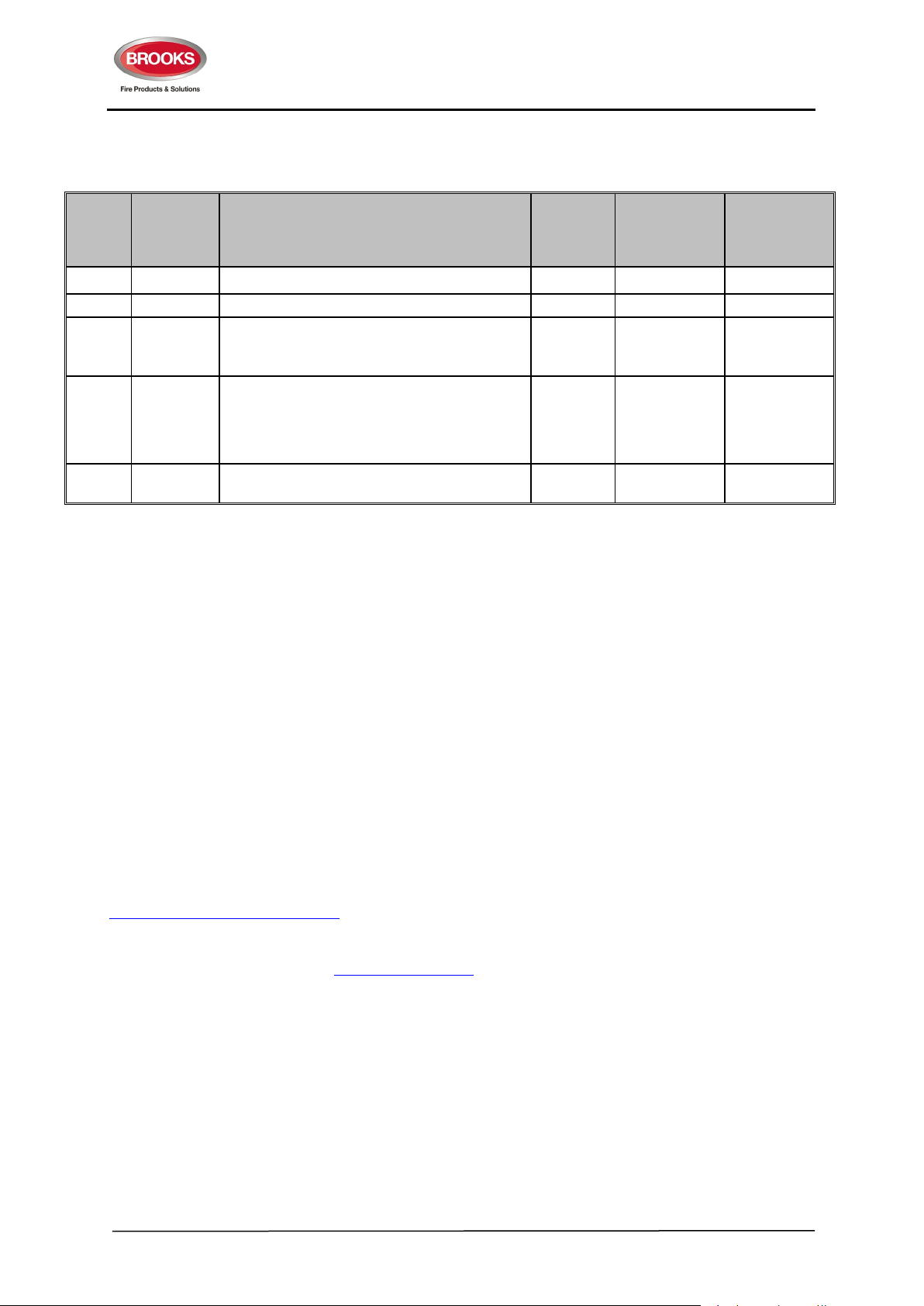
DOCUMENT HISTORY
Issue Date Description
Draft 10/12/07 Original Document. Draft W. Zhong A. Shenouda
1.0 20/3/09 Updated after reviewing V1.0 W. Zhong A. Shenouda
Add sounders datasheet & update table 9.
1.1 23/11/11
1.2 15/7/13
1.3 3/12/19
Review & correct, all label to all figures, correct
calculation example in Appendix D.
Modify the table for Gas Control Board
(SUB928) DIP Switch (8 ways) SW1
Configuration. Bit 5 is reused to select whether
the gas discharged sensor input activates the
alarm conditions
Update document, drawings, logo and add
warning signs with voice & speaker
S/W
Version
V1.0 W. Zhong E. Thein
V1.2 W. Zhong A. Shenouda
V1.2 A.S. A.S.
Written By Checked By
Documentation Feedback
If you have any comments or suggestions regarding this manual, please contact Brooks Technical
Services.
We welcome your valuable feedback to further improve our future manuals.
Please include the following information:
• Product name and version number (if applicable)
• Manual part number and revision (found on the front cover)
• Page number
• Brief description of the content which you think should be improved or corrected
• Suggestions for improvement
Send email messages to:
Please note the email address above is for documentation feedback only. If you have any technical
issues, please visit our web site www.brooks.com.au
and follow the links to the “Technical Support” or
“Enquiry” pages or contact your nearest branch.
7
Page 8

FT2GAS Gaseous Extinguishing System
Rev No. 1.3
1. ABOUT THIS MANUAL
1.1 Purpose
This manual is designed to be the reference point for the Brooks Dual Zone Gaseous Control System
and provides the technical and operational instructions to the installer / user. The document is intended
to be used by the end user, service and commissioning personnel. It provides detailed information
required for installation, commissioning and operation.
The manual provides the following details for the Brooks Gaseous Extinguishing System:
• Technical instructions
• Operating instructions
• Indicators and controls
• Input and output cabling and connectivity.
• Power supply calculation documents
• Datasheets
• Block wiring diagrams
1.2 Referenced Documents
AS7240.2 Fire detection and alarm systems
Part 2: Control and indicating equipment (ISO7240-2:2003, MOD)
AS7240.4 Fire detection and alarm systems
Part 4: Power supply equipment (ISO7240-4:2003, MOD)
NZS4512-2003 New Zealand Standard
Fire Detection and Alarm Systems in Buildings
AS4214-2002 Australian Standard
Gaseous fire extinguishing systems
AS1670.1-2015 Fire detection, warning, control and intercom systems-System
Design and commissioning – Part 1: Fire
AS/NZS 3000-2007 Australian / New Zealand Standard
Electrical Installations (Known as Australian/New Zealand Wiring Rules)
8
Page 9
FT2GAS Gaseous Extinguishing System
Rev No. 1.3
2. FT2GAS TECHNICAL DESCRIPTIONS
2.1 System Overview
A typical Brooks FT2GAS system is comprised of the following:
• Brooks FT2 Dual Zone control board (SUB922) and Zone Display Board (SUB923)
• Brooks Gas Extinguishing Control board (SUB928) and Gas Display board (SUB929).
• Switch Mode AC/DC Power Supply and backup batteries
• A combination of Brooks System Warning Signs
• Brooks Local Control Stations
• Brooks Dual Strobe Modules
• Brooks voice / tone warning speakers
• Optional Panasonic web server for remote monitoring of the system.
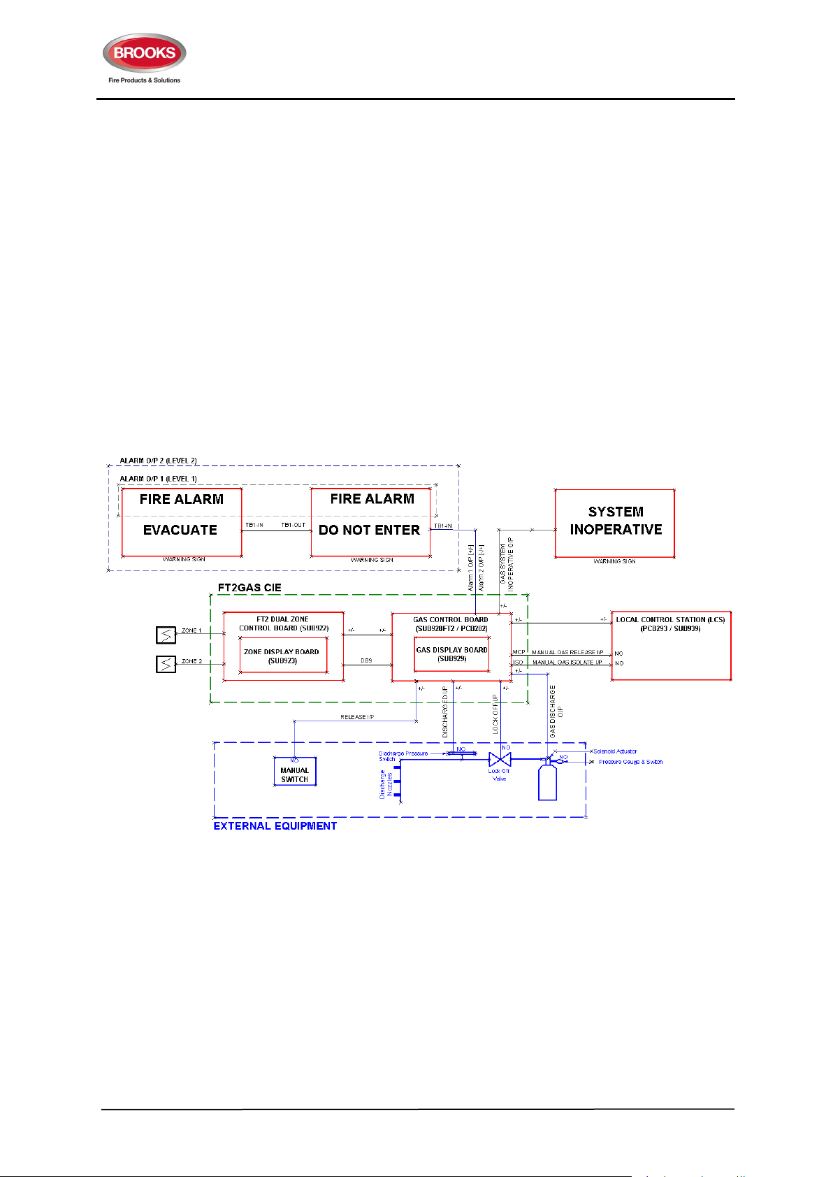
Figure 1 below illustrates some of the various components of the system.
Figure 1 Gaseous Extinguishing System Overview
The FT2 Dual Zone control board (SUB922) and the Zone Display Board (SUB923) shown in Figure 1
forms the two-zone fire panel functions that meets the requirements of the Australian Standards
AS7240.2 & AS7240.4. In addition, the board provides RS232 output to connect to an optional web
server for remote monitoring over Ethernet.
The plug-in Gas Control Board (SUB928) and the Gas Display Board (SUB929) in Figure 1 are designed
to provide the control and monitoring of a complete gaseous extinguishing system that meets the
requirements of the relevant clauses of the Australian extinguishing standard AS4214.
The standard FT2GAS system is fitted with a 150 Watt switch mode power supply (5A @ 28V) and can
house up to 2x12Ah sealed lead acid (SLA) batteries. A battery and power supply calculation should be
9
Page 10

FT2GAS Gaseous Extinguishing System
Rev No. 1.3
performed to verify the suitability of this standard product for use in the intended application, refer to
Appendix D on page 39.
2.2 Features
The Brooks dual zone gaseous extinguishing control system has the following features:
• An intelligent dual microprocessor system which combines both the two zone CIE functions and
the dual zone gas controller functions.
• Fully supervised power supply to meet the requirements of the Australian standard AS7240.4.
• Intuitive indication and controls via the well-grouped LED indicators and momentary switches.
• Fully supervised input circuits, including two fire detection zone inputs, one gas lock-off valve
input, one manual release input and one gas discharged sensor input.
• Fully supervised system inoperative warning sign 24V output rated @ 0.5A maximum.
• Fully supervised 2 wire system outputs for level 1 and level 2 alarms to Brooks warning signs
(Level 1: alarm 1 [+/-] & Level 2: alarm 2 [-/+]) rated @ 3A maximum. Note: [+/-] & [-/+] means
polarity changes accordingly to level 1 or 2.
• Fully supervised gas release output rated @ 5A maximum.
• Fully supervised 24V output for warning devices or sounders (Ancillary Control Facility, ACF)
rated @1A maximum. The output, once activated, can be disabled separately via the silence
(alarm device) switch.
• Common Alarm dry-contact relay output rated @ 2A maximum.
• Common Fault (Defect) dry-contact relay output rated @ 2A maximum.
• Common Isolate dry-contact relay output rated @ 2A maximum.
• Two alarm dry-contact relay output for alarm 1 and alarm 2 rated @ 2A maximum.
• One four-wire Local Control Station (LCS) interface. Both the local gas isolate control and the
local gas release control are fully supervised for open-circuit and short-circuit faults.
• Adjustable gas release timer settings via a built-in DIP switch.
• Provision for connection of an optional Panasonic web server to provide Ethernet connectivity
with web pages and email alerts.
• Transient suppression protection compromises metal oxide varistors (MOV) and transorbs to all
inputs and outputs.
Note: the current rating mentioned above is the maximum current capacity of the outputs, a power supply
calculation must be performed to ensure that the power supply capacity is sufficient to run the system
in full alarm condition without exceeding the maximum current rating of the power supply.
10
Page 11
FT2GAS Gaseous Extinguishing System
Rev No. 1.3
2.3 Specifications
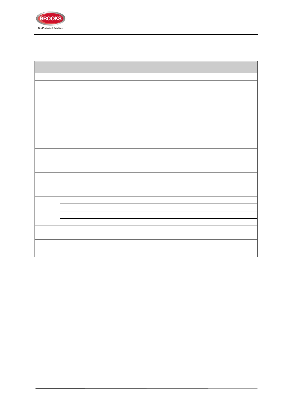
Table 1 General Specifications
Feature Specification
Mains Power Supply 230V AC, +/- 20%. Wattage 150W (maximum 5 A @28V)
Standby Battery
System Access
Security
Access Security for the
Local Control Station
Operating
Temperature
2 x 12V sealed lead acid batteries up to 12 AH, refer to power supply calculations,
APPENDIX D on page 39
Access Level 1: All the LED indicators are viewable through the locked transparent
window on the front door.
Access Level 2: All the controls are accessible via the front door using a 003 key.
Access Level 3: The system configuration DIP switch is behind both the front door
and the front plate. To change the system configurations, the technician needs to
open the front door, unscrew the front plate and change the DIP switch settings or
replace fuses.
Access Level 4: The control and indicating circuits are behind the front plate. To
upgrade its firmware or, the technician needs to open the front door, unscrew the
front plate and replace the microcontroller.
The gas isolate switch is a push button (with LED) accessible by lifting a plastic flap
cover.
The gas release switch is a yellow manual call point (with built-in LED and without
glass) accessible by lifting a plastic flap cover.
0°C to +40°C.
Operating Humidity 5-95%, non-condensing.
IP Rating IP31
Enclosure
Design Standards
Applications
Material 1.5mm zinc anneal steel powder coated oyster.
Dimension 400mm H x 320mm W x 165mm D (with door closed)
Weight 12Kg. (without backup battery and web server)
Gaseous Extinguishing Systems – AS4214-2002 amdt 1
CIE – AS7240.2-2004, AS7240.4-2004
Not suitable for use within any hazardous locations unless applying proper safety
techniques according to the related hazard regulations. Installed in an indoor
environment only.
11
Page 12

FT2GAS Gaseous Extinguishing System
Rev No. 1.3
2.4 Operation
2.4.1 Display Layout
The FT2GAS gaseous extinguishing control system display is shown in Figure 2
.
Figure 2 Dual Gaseous Extinguishing System Display Layouts
All the control buttons and LEDs on the front display of the control panel, with the exception of the
Service Master Abort switch, are a pushbutton covered with a polycarbonate overlay decal and clearly
labeled with their function.
When the system is in the normal condition, only the “Operation” (green) LED will be illuminated.
All other LED indications will be off.
12
Page 13

FT2GAS Gaseous Extinguishing System
Rev No. 1.3
2.4.2 System Controls
The system controls can be carried out by operating the momentary push-button switches on the front
display whilst the remote control is carried out by switches on the Local Control Station and / or the gas
valves of the gas protection equipment. The system controls are detailed in Table 2 below.
Table 2 System Controls
Location Control Condition Description
FT2 section of
Front Display
Gas
Extinguishing
Section of
Front Display
Local Control
Station
(section 4.9.4)
Zone 1 or 2
Alarm Test
Zone 1 or 2
Fault Test
Zone 1 or 2
Disable
Silence
Alarm
Devices
System
Reset
LED Test
Service
Master
Abort Button
Gas
Release
Gas Isolate
Zone 1 or 2 is not
in alarm or fault
condition.
Zone 1 or 2 is not
in alarm or fault
condition.
Zone1 or 2 is in
any condition.
Output for alarm
devices (ACF) is in
the active state.
CIE is in Fault or
Alarm conditions.
Press and hold
both Silence
Buzzer and Reset
buttons.
Correct operation
of this function can
only be expected
when the system is
in “normal” status.
CIE is in any
condition
CIE is in any
condition
The LCS gas
release control has
not been activated.
Perform Zone 1 or 2 Alarm Test (internal to the CIE
only). The alarm test state will be cancelled
automatically when the internal test is completed.
Perform Zone 1 or 2 Fault Test (internal to the CIE
only). The fault test state will be cancelled
automatically when the internal test is completed.
Disable or re-enable Zone 1 or Zone 2.
Disable or re-enable alarm devices.
Reset alarm condition, alarm devices must be
silenced first.
Reset fault conditions.
Any condition were not rectified will be re-activated.
When the control is activated:
• All LEDs, except CPU Fault and Service Master
Abort LEDs illuminate.
• The buzzer turns ON.
NOTE: When the system is reset from alarm or fault
conditions, this function on FT2 and gas front displays
will be disabled for approximately 10 seconds in order
to ensure that no further fault or alarm is to be reestablished.
Pressing the switch will cause the following:
• Gas discharge output is electrically isolated.
• Service Master Abort LED Illuminates.
• Gas Disabled LED illuminates.
nd
Illuminates both Gas Externally Released and 2
Alarm – Timer Running LEDs and starts the CIE gas
release timer. Overrides the LCS Gas Isolate switch.
Inhibits the LCS gas discharge output preventing an
automatic gas discharge from occurring due to the
alarm activation of both alarm zones.
External
Equipment
(Gas)
Gas
Discharge
Gas
Release
Gas Lock-off
CIE is in any
condition
CIE is in any
condition
CIE is in any
condition
To monitor the system gas pressure/flow sensor and
confirm gas flow through the system pipe-work.
When the switch operated, the Gas Discharged LED
is activated.
Monitors for activation of the gas release via a
mechanical release action (external equipment). Both
the alarm signs and the gas discharge output activate.
Overrides the LCS Isolate switch/control.
To monitor the system gas pipe-work lock-off valve
position.
With the valve closed the GAS FAULT LED is
activated and system inoperative sign illuminates.
13
Page 14
FT2GAS Gaseous Extinguishing System
Name
Period
On Time
Off Time
Name
Flash times
Color
Pattern
Pattern
Rev No. 1.3
2.4.3 Buzzer & LED Indicating Patterns
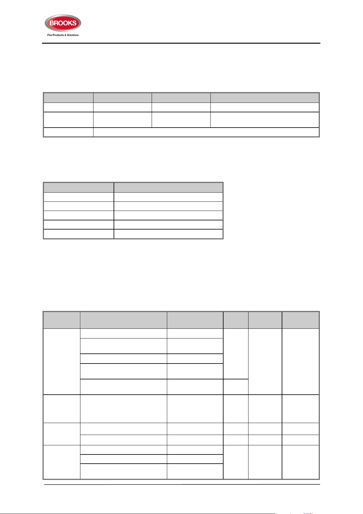
The CIE buzzer uses the following patterns to indicate the system conditions.
Table 3 Buzzer Indicating Patterns
Pulsing 3s 2s 1s
Key Pressed 40ms 40ms
Continuous Buzzer sounds continuously
The CIE LED indicators use the following flash patterns to signal the system conditions.
Table 4 LED Flash Patterns
Flash fast One flash every 0.5sec
Flash 1 One flash every 2.5sec
Flash 2 Two flashes every 2.5sec
Flash 3 Three flashes every 2.5sec
Steady ON Steady illumination
Always OFF, only one beep when
pressed
2.4.4 System Indications
The dual zone gaseous extinguishing control system condition indicating LEDs and flash patterns are
described in Table 5. The default state of the LED indicators and the buzzer are OFF, if it is not defined
Table 5 below.
Table 5 System Indicating LEDs and flash Pattern
Type CIE Conditions LED Name
One zone alarm 1st Alarm
Both Zone 1 and Zone 2 alarm
Fire
Fault Fault All Fault indicators Yellow
Test
Disablement
Gas release output activated Gas Initiated
External gas release control
activated
Gas discharged sensor input
activated
Zone Alarm Test Zone Alarm Test Red Steady ON Off
Zone Fault Test Zone Fault Test Yellow Steady ON Off
Zone 1 Disabled Zone 1 Disable
Zone 2 Disabled Zone 2 Disable
Gas Discharge Inhibited via LCS
isolate switch
2nd Alarm – Timer
Running
Gas Externally
Released
Gas Discharged Blue
Gas Discharge
Inhibited
LED
Red
Yellow
LED
Fast Flash
Based on
fault types
(section
2.4.5)
Steady ON
Buzzer
Pulsing
Continuous
Off
14
Page 15

FT2GAS Gaseous Extinguishing System
Color
Pattern
Pattern
Flash 2
Zone short circuit fault.
Rev No. 1.3
Type CIE Conditions LED Name
Gas Discharge Disabled by the
Service Master Abort switch or
the gas lock-off valve controls
Gas Service Master Abort switch
activated
Operation Mains power available Operation Green Steady ON Off
Silence
Alarm
Devices
Silence
Buzzer
LED Test
Alarm Devices output activated
Alarm Devices output (ACF) deactivated
Buzzer is silenced manually Silence Buzzer Yellow Steady ON OFF
The system is in the LED test
conditions
Gas Discharge
Inhibited
Service Master
Abort
Alarm Devices –
Silence - “Act.”
Alarm Devices –
Silence - “Sil.”
All the LEDs except
the Gas Fault and
the CPU Fault LEDs
LED
Yellow
Red Steady ON
Yellow Steady ON
N/A Steady ON Continuous
LED
Steady ON
Buzzer
Off
Off
The local gas control station (LCS) has an integrated buzzer and LED indicator. Both the audible and
visible indicators will remain ON as long as the LCS gas isolate control switch is activated.
2.4.5 Fault Indications
Many fault LED indicators have multiple indicating patterns to provide more information on the causes
of the faults. The fault LED indicating patterns are detailed Table 6 below.
Table 6 Display Fault LED Indications
LED Indicator LED Pattern Description
Steady ON Multiple faults detected.
Zone Fault
Alarm Devices
Fault (Flt.)
CPU Fault Steady ON CPU fault condition detected.
System Fault
PSU Fault
Earth Fault
Gas Fault Steady ON Gas system fault. This indicator is on the dual zone section of the keyboard.
Flash 1 Zone open circuit fault.
Flash 3 Zone test fault. A fault is detected during the zone alarm/fault test.
Steady ON Multiple faults detected.
Flash 1 Alarm devices open circuit fault.
Flash 2 Alarm devices short circuit fault.
Steady ON Multiple faults detected
Flash 1 FT2 communication fault (only if the Panasonic web server is installed)
Flash 2 FT2 display board fault
Flash 3 Monitored power supply output failed (Gas module power supply failed).
Steady ON Multiple power supply faults detected.
Flash 1 Main high fault.
Flash 2 Mains low or charger low fault.
Flash 3 Battery low fault
Steady ON Multiple faults detected.
Flash 1 A leakage between the GND (-Ve) and the earth is detected.
Flash 2 A leakage between the +24V and the earth is detected.
15
Page 16

FT2GAS Gaseous Extinguishing System
Rev No. 1.3
In addition to the LED indicators on the system front display, there are four yellow fault LED indicators
located on the gas control board (SUB928) inside the cabinet. The internal LED indicating patterns are
described in Table 7 below.
Table 7 Gas Control board Fault LED Indications
LED Indicator LED Pattern Description
Steady ON Multiple faults detected.
Gas
Signs
Inputs
Local
Flash 1 Gas module power supply fault
Flash 2 Gas release output fault
Flash 3 Gas module flash memory fault.
Steady ON Multiple faults detected.
Flash 1 System inoperative warning sign output fault
Flash 2 Alarm warning sign output fault
Steady ON Multiple faults detected.
Flash 1 Gas lock-off valve input fault.
Flash 2 Manual gas release input fault.
Flash 3 Gas discharged sensor input fault.
Steady ON Multiple faults detected
Flash 1 LCS manual gas release input fault.
Flash 2 LCS isolate input fault.
Flash 3 Gas master isolate input fault or display connection fault.
16
Page 17

FT2GAS Gaseous Extinguishing System
Rev No. 1.3
2.5 CIE Inputs and Outputs
2.5.1 Fire Detection Zone Inputs
The zone specifications and the compatible devices are listed Table 8 below.
2.5.1.1 ZONE INPUT CIRCUIT SPECIFICATIONS
Table 8 Zone Input
Item Description
Number of zones in one CIE 2 zones
Number of detectors per zone 0 – 40, including Manual Call Points (MCPs) if any
Maximum number of detectors in alarm per
zone
Zone current per zone 0 – 51mA
Typical Zone quiescent current per zone 5mA
Typical zone input resistance in alarm
conditions per zone
Up to 2 detectors per zone, including MCPs, heat and/or
smoke detectors.
560 Ohm
The typical zone input circuit is shown in Figure 3 below
Figure 3 Zone Input Circuit
Each zone input circuit is fully supervised for open circuit and short circuit faults. The EOL resistor type
is 3K9, 1W, 1%, metal film.
2.5.1.2 ZONE INPUTS COMPATIBLE ACTUATING DEVICES
Table 9 Compatible devices
Part No. Description
4452 Conventional multi detector (recommended)
Note:
Only smoke detectors can be used in gaseous extinguishing systems.
17
Page 18
FT2GAS Gaseous Extinguishing System
Rev No. 1.3
2.5.2 Control Input and Output
2.5.2.1 Non Supervised Outputs
The standard FT2 module provides the following five non-supervised outputs:
• Alarm relay output, changeover voltage free contacts
• Fault relay output, changeover voltage free contacts
• Isolate relay output, changeover voltage free contacts
• Zone alarm level 1 relay output, changeover voltage free contacts
• Zone alarm level 2 relay output, changeover voltage free contacts
The current carry capacity of each relay contacts is 2A.
The zone alarm level 1 relay and the zone alarm level 2 relay are only activated by the zones. The LCS
gas release input on the gas manual release input do not change the states of the two zone relay outputs.
2.5.2.2 Alarm Devices Output
FT2 control board provides 22-30V DC supervised output which can be used to activate warning devices
such as sounders, strobes, etc. The front display of FT2 has a segregated section for warning system
output which includes a disable facility with LED to confirm switch operation, fault and fire indications.
The warning system output can also be used to control external relays to control ancillary equipment.
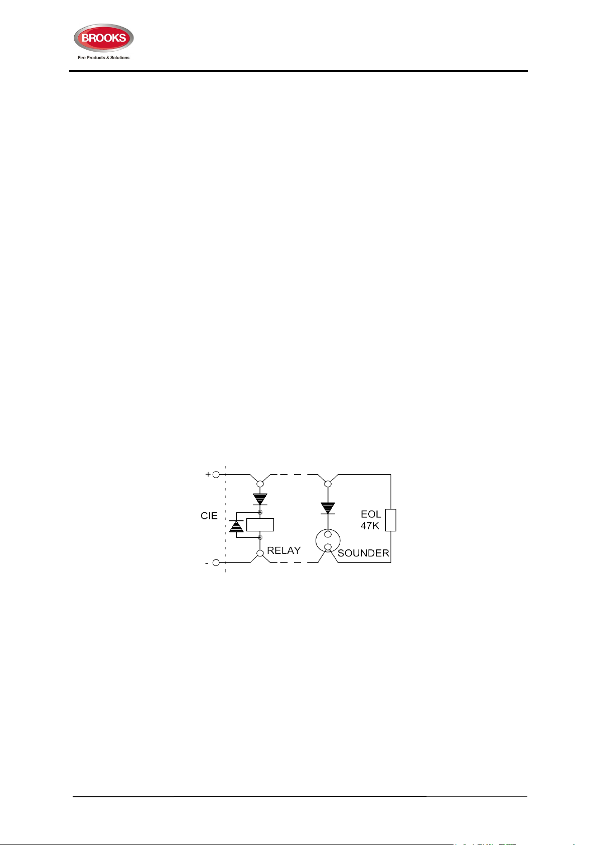
Figure 4 below shows the connection diagram and end of line resistor. Series diode must be fitted if the
ancillary devices have no polarity.
NOTE: The voltage polarity is shown with the output in the active state.
Figure 4 Typical Relay or Sounder Control Circuit
The alarm devices (shown as ACF on the (PCB) output is 22-30V DC, maximum current is 1A. The
output is fully supervised for open and short circuit faults. The EOL resistor type is 47K, 1/2W or 1W,
1%, metal film.
2.5.2.3 Extinguishing System Inoperative Sign Output
The gas control board provides a supervised output to activate the Extinguishing System Inoperative
warning sign. The output is 22-30V DC @ 0.5A and fully supervised for open and short circuit faults.
The EOL resistor type is 20K, 1/2W or 1W, 1%, metal film.
For more details, refer to the data sheet of the system inoperative sign in Brooks product datasheets in
Appendix I 4.9.2 Warning Signs
18
Page 19
FT2GAS Gaseous Extinguishing System
SOLENOID
Rev No. 1.3
Standard Warning Signs on page 48.
2.5.2.4 Fire Alarm / Do Not Enter and Evacuate Signs Output
The gas control board provides a fully supervised bi-directional 22-30V DC / 3A max (current capacity)
to activate a number of gas warning signs (depends on the power supply and battery capacity), refer to
power supply calculation sheet in appendix D on page 39.
The voltage output from the gas module SUB928 has 3 states:
1. Normal, monitoring +24V limited to <1.5mA
2. Level 1 Alarm, active condition is -24V
3. Level 2 Alarm, active condition is +24V
The nominal voltage output of level one alarm is +24V DC when measured across L1-/L2+ and L1+/L2of the connector TB3. The level two voltage output is -24V DC when measured across same terminals.
The output is fully supervised for open and short circuit faults. The EOL resistor type is 20K, 1/2W or
1W, 1%, metal film.
The two-wire system of the alarm warning signs output is compatible with Brooks warning signs and
tone / voice sounders.
For more details, refer to the data sheet of the Brooks warning signs in Brooks product datasheets in
appendix I on page 48.
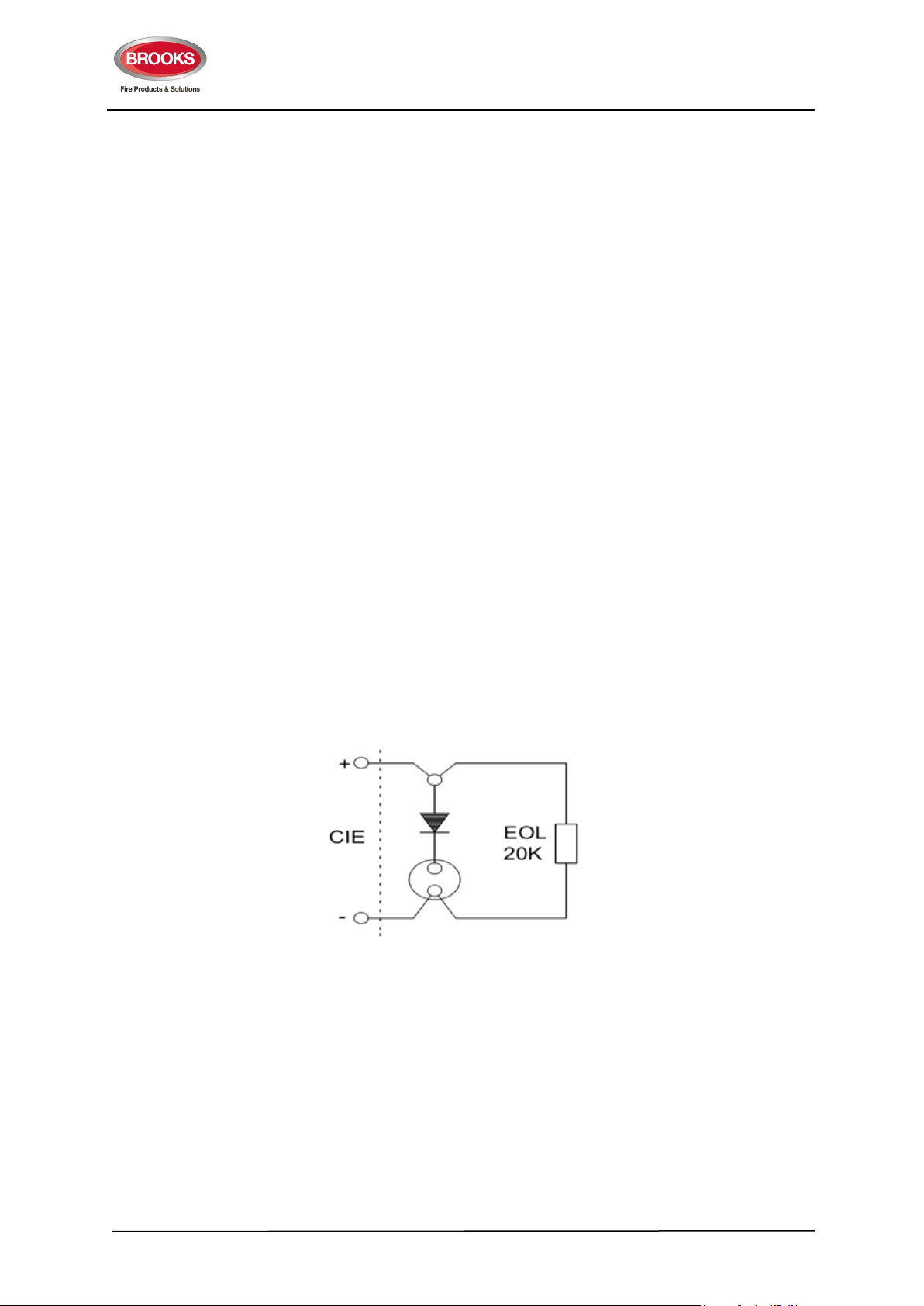
2.5.2.5 Gas Discharge Output
The system gas discharge output is 22-30V DC with up to 5A current capacity. The output is fully
supervised for open and short circuit faults. The EOL resistor type is 20K, 1/2W or 1W, 1%, metal film.
Note: CIE Voltage polarity shown in Figure 5 below is for the output in the active state
Figure 5 Typical Gas Discharge Output Control Circuit
Notes:
1. The series diode is rated @ 3A (1N5404), Brooks part number DI600. If the discharge output
is required to be rated @ 5A continuous, a higher rated diode should be used.
2. The FT2GAS must have suitable power supply to support additional current required by Gas
discharge output if a 5A continuous current is needed.
2.5.2.6 External Supervised Inputs
The system has the following external supervised inputs.
19
Page 20

FT2GAS Gaseous Extinguishing System
LCS
10K
27K
EOL
27K
EOL
MCP
ISO
0V (GND)
10K
24V
GAS
CONTROL
BOARD
24V
0V (GND)
MCP
ISO
TB1 CON1
(SUB928)
Rev No. 1.3
• Gas release input monitors the gas manual release mechanism, normally located at the head
of the extinguishing agent contactor. When this input is activated, the “Gas Externally Released”
LED illuminates, the level 2 alarm signs will be activated immediately. This input will not initiate
the automatic sequence of gas releasing.
• Gas lock-off valve input, this input monitors the lock-off valve position. If the valve is closed,
the input will be active which causes the “Gas Fault” LED to flash once every 2.5 seconds and
the Extinguishing System Inoperative sign to illuminate.
• Gas discharged sensor input, the gas pressure switch or flow sensor is supervised via this
input and confirms that the gas has been released. A pressure switch will normally operate when
the extinguishing agent bottle has low pressure indicating the bottle has emptied or is low. A
flow sensor will operate when the extinguishing agent is discharged through the system pipework past the sensor.
The external inputs are fully supervised for open and short circuit faults.
Figure 6 Supervised Input Circuit
Both the EOL resistor and the active resistor are 47K, 1/2W or 1W, 1%, metal film.
2.5.2.7 Local Control Station (LCS)
The FT2GAS system provides an interface to multiple remote gas control stations. Only the Brooks LCS
can be connected to this interface. It includes the following four signals,
• LCS +24V,
• LCS Ground,
• LCS Gas Release input,
• LCS Gas Isolate input.
Both LCS gas release input and gas isolate input are fully supervised for open and short circuit faults.
Figure 13 page 35.
20
The EOL resistor is 27K, 1/2W or 1W, 1%, metal film. The active resistor is 10K, 1/2W or 1W, 1%, metal
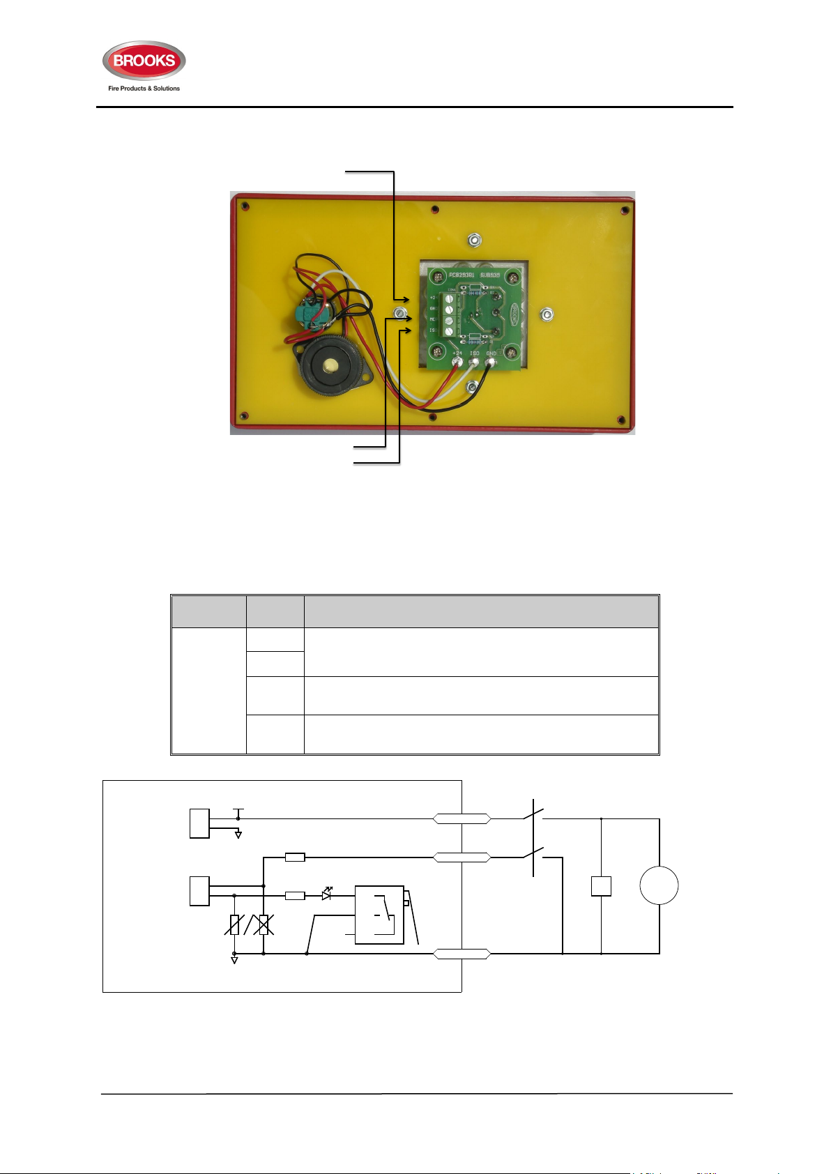
film. The schematics for the LCS can be found in
Figure 7 Remote Station Input Circuit
Page 21
FT2GAS Gaseous Extinguishing System
Rev No. 1.3
2.5.2.8 External Buzzer
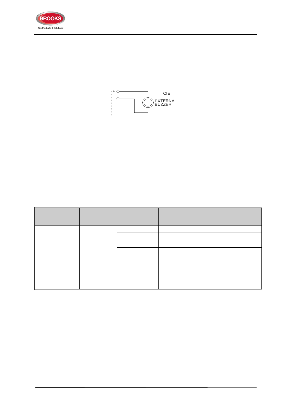
The FT2 control board has an internal PCB mounted buzzer which meets the buzzer sound level
requirement of 65dB at 1 metre distance with the door closed. If the internal buzzer sound level is
insufficient, an external buzzer can be installed to the CIE front plate. To disable the PCB mounted
buzzer, the resistor R8 located just next to the PCB buzzer on the FT2 control board needs to be
removed. Refer to the board layout under section 4.1.1 page 29.
Figure 8 External Buzzer Circuit
2.5.2.9 DIP Switch Configurations
Two DIP switches are provided in FTGAS for system configuration. One 4-way DIP switch, SW1 on the
FT2 control board (SUB922), Refer to section 4.1.1 page 29.
Another 8 way DIP switch, SW1 on the dual zone gas control board (SUB928), refer to section 4.1.2 on
page 31. The gas control board is mounted above the FT2 main control board and connected together
via a 9-pin D-range connector. To access DIP switch, SW1 on the FT2 main control board, disconnect
the power first then carefully remove the plug-in dual zone gas control board.
Table 10 FT2 Control Board (SUB922) DIP (4 way) Switch SW1 Configuration
Purpose
Zone latch 1
Zone alarm
verification
Zone relay controls 3 & 4 must set to 11
Switch Bank
Number
2
Status
On= 1 OFF= 0
1 Zone alarm is non-latching
0 Zone alarm is latching (default setting)
1 Enable alarm verification (not used with FT2GAS).
0 Disable alarm verification. (default setting)
Description
Zone Relay 1 activates only when one zone or
both zones is/are in alarm conditions,
Zone Relay 2 activates only when both zones are
in alarm conditions.
Note: The other settings of the two switches are
not used in FT2GAS but are used in FT2 system.
21
Page 22
FT2GAS Gaseous Extinguishing System
0 0 0 0 200 milliseconds
1 0 0 0 40 seconds
1 1 0 0 60 seconds (default setting)
The gas discharge control is activated
Rev No. 1.3
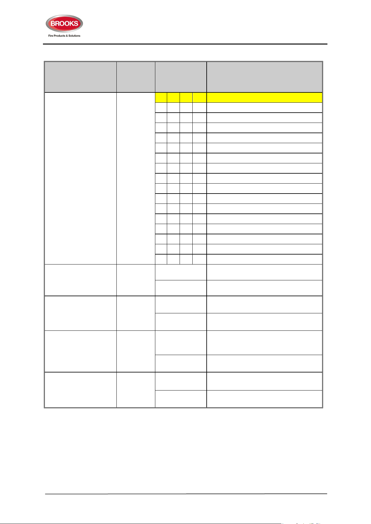
Table 11 Gas Control Board (SUB928) DIP Switch (8 way) SW 1 Configuration
Purpose
Gas release timer
selection.
In normal conditions,
the timer is started by
the dual alarm
conditions or the
remote release
controls.
The gas will be initiated
at the end of the
specified period.
Whether the gas
discharged sensor
input activates the
alarm conditions.
Whether the gas
release is stopped if
the system is
inoperative.
Whether the gas
discharge control is
activated by one zone
alarm input or two zone
alarm inputs.
Whether the remote
gas release activates
the gas timer or gas
release directly.
Switch
Bank
Number
1-4
5
6
7
8
Status
On = 1 Off = 0
Description
4 3 2 1 Switch number
0 0 0 1 5 seconds
0 0 1 0 10 seconds
0 0 1 1 15 seconds
0 1 0 0 20 seconds
0 1 0 1 25 seconds
0 1 1 0 30 seconds
0 1 1 1 35 seconds
1 0 0 1 45 seconds
1 0 1 0 50 seconds
1 0 1 1 55 seconds
1 1 0 1 70 seconds
1 1 1 0 80 seconds
1 1 1 1 90 seconds
1
0
1
0
The gas discharged sensor input activates
the level 2 alarm conditions.
The gas discharged sensor input does not
activate any alarm conditions.
The gas release is not disabled by the
system inoperative.
The gas release is disabled if the
system is inoperative (default).
The gas discharge control is activated
1
by any one of the two zone alarm
inputs.
0
1
0
by two zone alarm inputs (default).
The LCS gas release activates the gas
timer
The LCS gas release activates the gas
release immediately.
22
Page 23
FT2GAS Gaseous Extinguishing System
Rev No. 1.3
2.6 Power Supply Unit (PSU)
2.6.1 PSU Specifications
The main power source of the standard FT2GAS system is a 150W switch mode power supply, the
maximum current capacity is up to 5A @ 28V DC. The PSU supports the following:
• Total current required for the internal circuits
• Battery charging current
• Maximum current required to drive external loads
• Current required for optional web server and any additional loads.
WARNING: The maximum CIE current capacity shall not be exceeded in any applications. Otherwise
the fuses on the control board may blow and the CIE hardware may be damaged. Check system design
against the power supply and battery calculation spreadsheet in Appendix D page 39.
Table 12 Basic mains power supply requirement
Characteristics Typical Range
Input Voltage Range 230V AC 170-264VAC
Input Voltage Frequency 50Hz 47- 63 Hz
Output Voltage 28V +/- 1%
AC Input Current < 2A Varies based on the applications
DC Output Current 5A @ 28V Varies based on the applications
Larger power supplies can be used depending on the applications. However, larger enclosures would
be required.
The output voltage of the power supply is factory set, it may need to be checked and calibrated on-site.
The calibration procedure is as follows.
• Use a calibrated and certified multi-meter to measure the DC voltage of the battery connection
(between TB1 POWER IN + and POWER IN -) on the FT2 control board or the battery terminals.
• Adjust the AC/DC power supply potentiometer until the multimeter reading is stabilized between
27.3V – 27.5V DC.
WARNING: 240V AC. Care must be taken when adjusting the AC/DC power supply. If you need to
remove the plastic cover protecting the 240VAC terminations use extreme caution. Always ensure the
cover is replaced correctly.
The standard FT2GAS system accommodates up to 12AH batteries.
23
Page 24

FT2GAS Gaseous Extinguishing System
Rev No. 1.3
2.6.2 PSU Supervision
The system constantly monitors the mains power supply, battery charger voltage and batteries and will
initiate a PSU fault if the voltage of the charger or batteries exceeds the limits as in Table 13.
Table 13 Power Supply Supervision Characteristics
Characteristics Threshold
Secondary Low Fault 24V, Measured on the battery terminals
Battery Automatic Cut Off 20.7V, Measured on the battery terminals, when the mains is not available.
Main Power High Fault 30.5V, Measured on the main power source output terminals
Main Power Low Fault 22.1V, Measured on the main power source output terminals
Secondary Charging
Voltage Low Fault
Automatic Battery Test
24.3V, Measured on the battery terminals
The system automatically runs on battery only for one hour every 70 hours and
closely monitors battery voltage during this period. The test terminates
automatically should any power supply fault or alarm condition was detected.
2.6.3 PSU Current Calculations
The following shall be calculated according to the application requirements of the related current
standards, such as AS7240.2, AS1670.1, NZS4512 and AS4214.
1. Battery capacity calculation
2. AC/DC power supply current capacity requirement
The typical system current consumptions are listed below.
Quiescent Current, I
Alarm Current, I
The alarm state current is measured when two zones are in high priority alarm conditions, all the outputs
are activated. The quiescent state current is measured when all the common condition relays except the
common fault relay are de energized. No power output current has been included.
WARNING: The current consumption data above does not include any current supplied to the external
devices. The actual current consumption shall be re-calculated based on the actual system
configurations. Refer to the power and battery calculation spreadsheet in Appendix D on page 39.
= 75 mA
Q
= 250 mA
A
24
Page 25

FT2GAS Gaseous Extinguishing System
Rev No. 1.3
3. INSTALLATION AND COMMISSIONING
The installation and commissioning of Brooks FT2GAS shall be carried out by qualified installers
following the requirements of all the related current standards and regulations, such as AS1670.1,
AS/NZ 3000 and AS/ACIF S-009. Additional procedures detailed in this chapter shall also be followed.
If any measurements are required during the installation and commissioning, only calibrated and certified
multimeter shall be used. The CIE test results and maintenance history shall be recorded in the form
provided in Appendix E – Commissioning Record on page 42, Appendix F – Equipment Record on page
44 and Appendix G – Maintenance Record on page 45.
3.1 Visual Inspection Checklists
Before applying any power to the panel, the following visual inspection shall be performed:
• Check cabinet general appearance for damage or dents.
• Ensure all modules firmly mounted and secured.
• Ensure mains cabling are correctly terminated before power up.
• Check earthing correctly terminated and secured before power up.
• Check that all ribbon cables are firmly secured without cuts on the insulation.
• Check all field cables and detector connections for correct polarity.
• Check that the End of Line (EOL) resistors are fitted to each detector circuit at the last detector.
Check that the EOL resistors are fitted to every supervised output at the last device and ensure that the
resistance values are configured as shown in the Block Wiring Diagrams section 5, page 55.
• Check all the jumpers and DIP switches are set correctly.
Should any of the above be compromised, please contact Brooks Australia Technical Support.
3.2 Resistance Check
Before applying any power to the system, resistance checks shall be carried out as per Appendix E –
Commissioning Record on page 42. The multimeter readings and inspection results shall be recorded
in the related spreadsheet shown in:
• Appendix E – Commissioning Record on page 42,
• Appendix F – Equipment Record on page 44 and
• Appendix G – Maintenance Record on page 45.
25
Page 26

FT2GAS Gaseous Extinguishing System
Rev No. 1.3
3.3 Functional Testing
This section describes the system testing and commissioning procedures to ensure that the FT2GAS is
fully functional. All field wiring shall be terminated in FT2GAS control panel except the gas release
circuit
3.3.1 FT2 System Test
3.3.1.1 Power Supply Check
Before applying any power to the system, ensure that the gas release circuit is replaced by a dummy
load. This load should be installed at the extinguishing gas equipment location NOT in the control panel.
It is recommended to use match head devices to simulate gas firing.
The voltage of each battery shall be measured, if the voltage is less than 10.7V, the battery shall be
replaced since it could have been deeply discharged or over its allowed life cycle.
• Disconnect the battery leads to the battery terminals.
• Turn ON the mains isolate switch and measure the voltage across the battery leads without
physical connection to the batteries.
• The DC voltage shall be 27.3V – 27.6V (factory set). If the voltage is not within the specified
limits, adjust the trimpot of the switch mode power supply until the voltage becomes within 27.3-
27.6V.
• Reconnect the batteries.
• Only the green “Operation” LED and “Gas Fault” LED should be illuminated.
• Press reset, only the “operation” LED would remain ON, any other indicators and the buzzer
must be OFF.
3.3.1.2 Alarm Test
1. Press the “Fire” test button of zone 1, the buzzer will sound and the fire LED illuminates steady
for approximately 3 seconds then turns OFF and the buzzer silences. No other LEDs shall be
illuminated.
2. Repeat step 1 for zone 2.
3. Use a smoke can to spray near a detector in the zone input (Alternatively, connect a 680Ω
resistor to the respective zone inputs to simulate zone alarm). Check for the following
conditions:
a) Both indicators on the panel for Zone 1 “Fire” LED and Alarm Devices-Silence “Act.”
LED should flash once every 0.5 second.
st
b) “1
Alarm” LED flashes once every 0.5 second
c) “Fire Alarm” warning sign illuminates (it may flash, depending on the DIP switch
setting).
d) Audible Alert tone is activated (if Brooks sounder is used).
e) Press “Silence Buzzer” button, the buzzer should mute.
f) Press “Silence Alarm Devices” (if audible sounders are used) then press “Reset” to
reset the alarm.
Note: Always push “RESET” after pushing “Alarm Devices-Silence”. This sequence
should be followed.
4. Repeat Step 3 for Zone 2 while zone 1 is inactive (i.e. no alarms) by pushing on “Disable button
under Zone 1.
26
Page 27

FT2GAS Gaseous Extinguishing System
Rev No. 1.3
3.3.2 Gas Extinguishing System Test
1. Simulate the actual alarm test in either one of the two zones following steps 3a) to 3d) under the
“Alarm Test” in section 3.3.1.2 page 26 and check the following:
• The “Fire” LED of the tested zone, “Silence Alarm Devices Act.” and “1
illuminate.
• “Fire Alarm” signs and audible alert tone (if used) should activate if configured via the DIP
switch (SW1) located on the Warning Signs Circuit Board (PCB291R1/SUB937). Refer to
area D2 in the Warning Signs Circuit Board layout in section 4.1.3 on page 33.
2. Continuing from step 3d), to simulate actual alarm test on the other zone, check for the following:
• The “Fire” LED of the zone under test and “2
nd
Alarm-Timer Running” LED should both
illuminate.
• Gas release timer will be running for the time delay set by the 8 way DIP switch SW1 on
the gas board control board (SUB928).
• “DO NOT ENTER” and “EVACUATE” signs will activate.
• Audible Evac tone will activate (if used).
st
Alarm” LED should
• When the timer times out, the “Gas Initiated” LED illuminates and gas will release.
• Gas discharge confirmation via gas discharged input will illuminate the “Gas Discharged”
blue LED if the Gas Discharge input is simulated to be active.
• Press “Silence Alarm Devices” button then press the “Reset” button.
3. Repeat step 3 and press the “Service Master Abort” switch before the timer times out, check the
following:
• “Service Master Abort” LED and “Gas Disabled LED” illuminate.
• The Gas is not released i.e. the “Gas Initiated” LED should never illuminate.
• Press “Silence Alarm Devices” button then press the “Reset” button.
3.3.3 Local Control Station (LCS) Test
1. Lift up the MCP cover then press the “Gas Release” switch, check the following:
• The LED integrated in the MCP switch illuminates.
nd
• The “2
• “Gas Externally Released” LED illuminates.
• Gas release timer starts running for a time delay set by the DIP switch.
Alarm-Timer Running” LED illuminates.
• “DO NOT ENTER” and “EVACUATE” signs will illuminate
• Audible Evac tone will activate (if used).
• When the timer times out, the “Gas Initiated” LED illuminates and the gas releases.
• Gas discharge confirmation via gas discharged input will illuminate the “Gas Discharged”
blue LED if the input is simulated to be active.
• Using a small screw driver, lift up the MCP button to mechanically reset the switch
27
Page 28

FT2GAS Gaseous Extinguishing System
Rev No. 1.3
2. Lift up the “Gas Isolate” flap then press the switch, check the following:
• “Gas Isolate” lamp integrated in the switch body illuminates.
• “Gas Discharge Inhibited” LED on the FT2GAS panel illuminates.
• Simulate the first and the second alarms, and ensure that the initiated LED remains OFF
i.e. gas is not released.
• Press the “Gas Isolate” switch again, system returns back to normal.
3.3.4 Fault Test
1. Press zone 1 and zone 2 “Fault Test” button, “Zone Fault” LED of each zone illuminates steadily
for approximately 3 seconds.
2. Remove a detector head or end of line resistor, the corresponding “Zone Fault” LED flashes once
every 2.5 seconds (open circuit), “Gas Fault” LED illuminates steadily and the “System Inoperative”
sign will activate.
3. Simulate short circuit across a zone, the “Fault” LED of that zone flashes twice every 2.5 seconds,
“Gas Fault” LED illuminates steady and the “System Inoperative” sign will activate.
4. Remove the end of line resistor of the ACF on the FT2 Main Control Board output and the “Alarm
Devices-Silence Flt.” LED flashes once every 2.5 Seconds. For short circuit test, the LED flashes
twice every 2.5 seconds.
5. Simulate open and short circuit on the warning sign output (Do not enter /Evacuate), “Gas Fault”
LED illuminates steady and the “System Inoperative” sign will activate.
6. Simulate open or short circuit on the system inoperative sign output and “Gas Fault” LED illuminates
steadily.
7. Simulate open or short circuit on the LCS outputs, “Gas Fault” LED illuminates steadily and the
“System Inoperative” sign will activate.
28
Page 29

FT2GAS Gaseous Extinguishing System
Rev No. 1.3
4. APPENDICES
4.1 Appendix A - Connections
The following are the connection details and printed circuit board layouts of the FT2 Control board and
Gas Extinguishing control board. The connection details to the remaining boards and equipment (PSU,
display boards, LCS, and Warning Signs) are shown in the block wiring Diagrams in on page 55.
4.1.1 FT2 Main Control Board
Figure 9 FT2 Control board PCB Layout (SUB922)
29
Page 30
FT2GAS Gaseous Extinguishing System
IDC 34
Rev No. 1.3
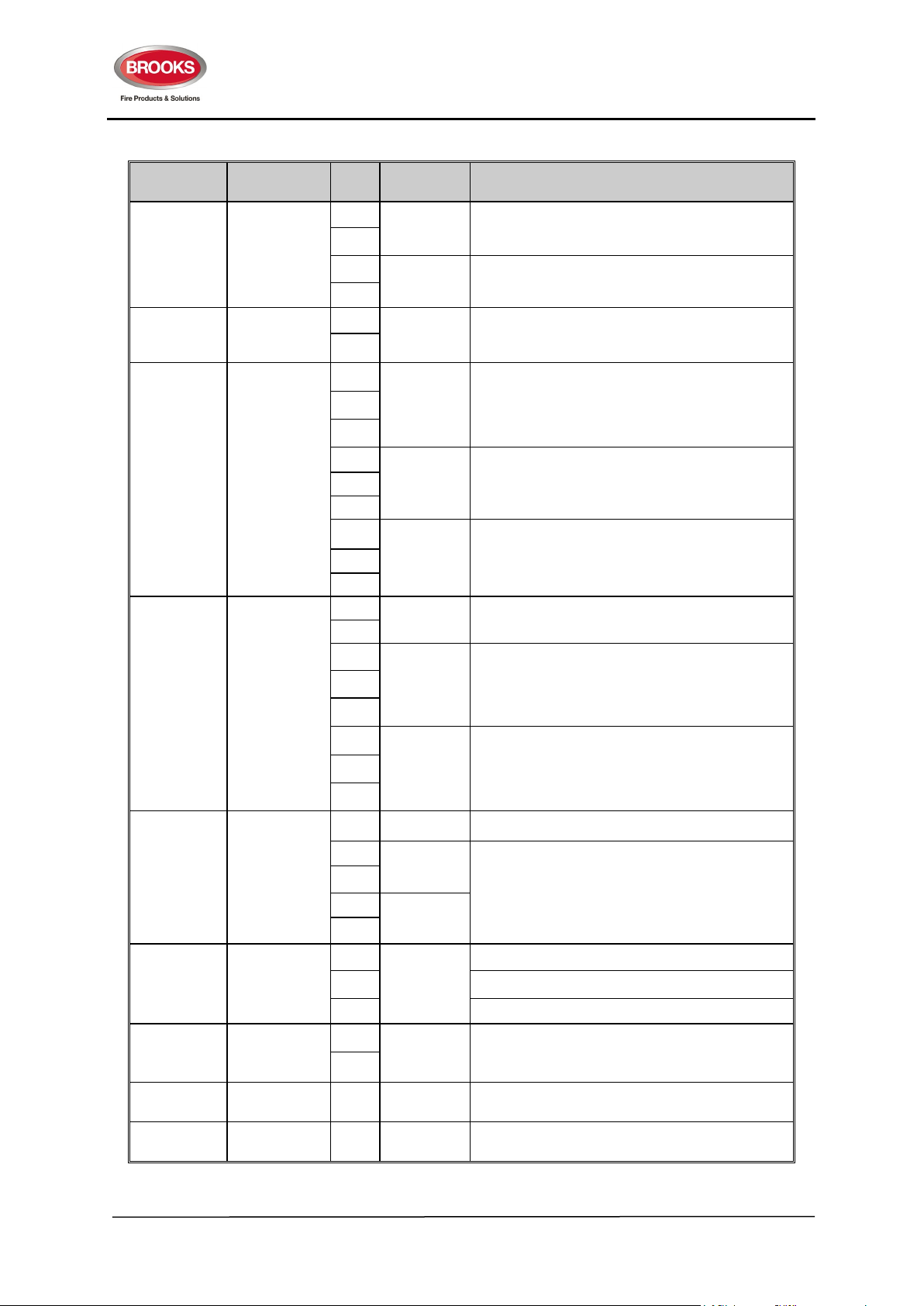
Table 14 FT2 Control Board Connections
Designator Type Pin Label Description
TB1
TB2
TB3
TB4
Removable
screw
terminal block
Removable
screw
terminal block
Removable
screw
terminal block
Removable
screw
terminal block
+
-
+
-
+
-
NO
NC
COM
NO
NC
COM
NO
NC
COM
+
-
NO
NC
COM
NO
NC
COM
POWER IN
BATTERY
POWER
OUT
ALARM
Power Input from the AC/DC power supply.
22-27.6V DC, <= 5A
External battery connection
22-27.6V DC, <= 5A
Power output to the Gas Module power input
22V-27.6V DC, <= 5A
Alarm relay output
Dry-contact output. <= 2A, < 30V
Fault relay output
FAULT
Dry-contact output. <= 2A, < 30V
NOTE - Relay is normally energized
ISOLATE
Disablements relay output,
Dry-contact output. <= 2A, < 30V
ACF 22V-27.6V DC, <= 1A
RELAY 1
OUT
RELAY 2
OUT
Zone alarm level 1 relay output.
Dry-contact output <= 2A, < 30V
Zone alarm level 2 relay output.
Dry-contact output <= 2A, < 30V
TB5
TB6
TB7
CON1
CON2
Removable
screw
terminal block
Removable
screw
terminal block
Removable
screw
terminal block
DB9 female
connector
connector
N/A EARTH Solid Earth connection shall be provided.
+
ZONE 1
-
+
-
ZONE 2
RX
TX Send Pin. Connects to Web Server RXD (R)
SERIAL
PORT
Compatible with approved detectors and MCPs.
With the following features,
• Alarm latching or non-latching
• Alarm Verification enabled or disabled.
Receive Pin. Connects to Web Server TXD (S)
GND Ground. Connects to Web Server GND (G)
+
BUZZER
-
External buzzer output,
An external buzzer is required only when the
sound level of the internal buzzer is insufficient.
N/A N/A Connect to Gas board plug-in connector CON1.
N/A N/A Connect to the FT2 Display Board.
30
Page 31

FT2GAS Gaseous Extinguishing System
Rev No. 1.3
4.1.2 FT2 Gas Extinguishing Control Board
Figure 10 Gas Control board PCB Layout (SUB928)
31
Page 32
FT2GAS Gaseous Extinguishing System
Rev No. 1.3
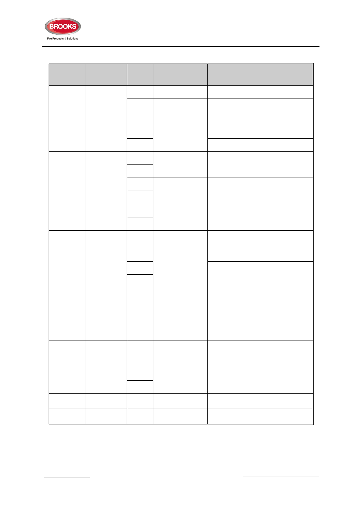
Table 15 Gas Control board Connections
Designato
r
TB1
TB2
TB3
Type Pin Label Description
EARTH E Earth connection to the gas module
Removable
screw
terminal block
Removable
screw
terminal block
Removable
screw
terminal block
+24
GND LCS GND
LCS INTERFACE
MCP LCS remote gas release input
ISO LCS remote gas isolate input
+
LOCK-OFF I/P
-
+
RELEASE I/P
-
+
DISCHGED I/P
-
SYS
INOP +
SYS
INOP -
L1+/L2-
WARNING SIGNS
L1-/L2+
LCS +24V output, 22V-30V, <=0.5A
gas lock-off valve input from lock off
valve
Manual gas release input from
Mechanical switch
Gas discharged sensor input from
discharge pressure switch
Gas system inoperative warning output,
22V-30V, <=0.5A
Level 1 & Level 2 alarm to warning
signs, “FIRE ALARM / EVACUATE” and
“FIRE ALARM / DO NOT ENTER”,
strobes and sounders as required.
At monitoring:
Polarity order at this pin pair is at ’+’ and
’-‘ 6V.
When activated:
’+’ and ’-‘ polarity for level 1 alarm,
’-’ and ’+‘ polarity for level 2 alarm.
22-30V DC, <=3A
TB4
TB5
CON1
CON2
Removable
screw
terminal block
Removable
screw
terminal block
DB9 male
connector
IDC 16
connector
+
GAS DISCH O/P
-
+24
POWER
GND
N/A N/A Connect to the FT2 control board CON1
N/A N/A Connect to the gas display board
32
Gas discharge output, 22V-30V, <=3A to
solenoid actuator or detonating device
on gas cylinders
Connect to the FT2 control board TB3
power output, 22V-30V, <=5A
Page 33

FT2GAS Gaseous Extinguishing System
Rev No. 1.3
4.1.3 Warning Signs PCB Layout
Figure 11 Brooks Warning Signs PCB Layout
Table 16 Warning Signs DIP Switch Setting
Status
Purpose
Switch
Number
1 = ON
0 = OFF
1 Single mode, the whole sign illuminates
Mode SW1
Buzzer SW2
Sign Flashing SW3
Not used SW4
0
1 Enable warning sign buzzer
0 Disable warning sign buzzer (default setting)
1 Enable sign flashing
0 Disable sign flashing (default setting)
Description
Dual mode,
level 1 alarm illuminates the top half “FIRE ALARM” while
level 2 alarm illuminates the bottom half “DO NOT
ENTER” or “EVACUATE”
33
Page 34

FT2GAS Gaseous Extinguishing System
Rev No. 1.3
Table 17 Extinguishing System Warning Signs Connections
Designato
r
TB1
TB2
TB3
Type Pin Label Description
Connect to TB3 L1+/L2- in
Removable screw
terminal block
Removable screw
terminal block
Removable screw
terminal block
L1+/L2-IN
L1-/L2+ IN
L1+/L2-OUT
L1-/L2+ OUT
L1 (+) IN
L1 (-) IN
L1 (+) OUT
L1 (-) OUT
L2 (+) IN
L2 (-) IN
L2 (+) OUT
L2 (-) OUT
2-WIRE SYSTEM
4-WIRE SYSTEM
Typically used
for retrofit – not
used in
Brooks
system)
4-WIRE SYSTEM
Typically used
for retrofit – not
used in
Brooks
system)
the gas control board, level
1 and level 2 alarm
Connect to TB3 L1-/L2+ in
the gas control board, level
1 and level 2 alarm
Connect to next warning
sign
Connect to level 1 (+) in a
gas system
Connect to level 1 (-) in a
gas system
To next level 1 sign
Connect to level 2 (+) in a
gas system
Connect to level 2 (-) in a
gas system
To next level 2 sign
TB4
Removable screw
terminal block
L1-/L2+
L1+/L2-
AUDIO MODULE
BUZZER +
BUZZER -
To Brooks Alert/Evac/Voice
module
Connect to optional external
buzzer for level 1 alarm
+
TB5
Removable screw
terminal block
MUTE L1
BUZZER
Connect to a switch to mute
the optional external buzzer
-
Notes:
1. Brooks warning signs require only 2 wire connection. The 4 wire option is provided for retrofit
situations where an existing 4 wire warning sign circuit is installed.
2. Brooks audio (Alert/Evac) / voice sounder can be connected to the same two wire system as
the warning signs.
3. If 4 wire system is used, the speaker shall be connected to TB4 in the warning sign board.
34
Page 35
FT2GAS Gaseous Extinguishing System
+
-
Isolate
MCP
24V
1
2
CON1
CON02
1
2
CON2
CON02
GND
+24
R4
27kR327k
R1
10k
R2
10k
GND
MCP GAS RELEASE
LED1
red
POWER IN
+
-
C
1
NO
2
NC
3
SW1
MICRO-SWITCH
24V
ISO
GND
INHIBIT SWITCH
3
4
3
4
BUZZER
LAMP
LAMP PART OF
INHIBIT SWITCH
INHIBIT SWITCH (ISO)
GAS RELEASE (MCP)
Rev No. 1.3
4.1.4 Local control station
Figure 12 (Photograph 2) Rear of Local Control Station
Table 18 Local control station connection
Type Label Description
24V
GND
Screw
Terminal
MCP
ISO
24V Supply from the control board
Connected internally to the gas release switch on the
front of LCS, “MCP” terminals from the control board
Connected internally to the gas isolate switch in LCS,
“ISO” terminal from the control board
35
Figure 13 Local Control Station Schematics
Page 36

FT2GAS Gaseous Extinguishing System
Rev No. 1.3
4.2 Appendix B – System Fuse Details
The system fuses are listed in Table 19 below.
Table 19 Fuse Specifications
Board Designator Circuit Protected Specification
FT2 Control
Board
SUB922R1
Dual zone
Control Board
SUB928R1
LCS Circuit
Board
SUB939
Warning Signs
Circuit Board
SUB937
F1 Main power input
F2 Battery power input
F3 Power output
F4 ACF Resettable, poly fuse, 1.1A, <= 30V.
F1 LCS Station Resettable, poly fuse, 0.5A, <= 30V.
F2
F3 Gas discharge output
F4 Alarm warning output
NIL NIL
NIL NIL
System inoperative
warning output
M205, glass sealed, fast blow or very fast blow,
<= 5A, defined by the application.
M205, glass sealed, fast blow or very fast blow,
<= 5A, defined by the application.
M205, glass sealed, fast blow or very fast blow,
<= 5A, defined by the application.
Resettable, poly fuse, 0.5A, <= 30V.
M205, glass sealed, fast blow, <= 5A, defined by
the application.
M205, glass sealed, fast blow or very fast below,
<= 3A, defined by the application.
Protection provided to voltage input by fuse F1
on Dual Zone Control Board SUB928R1
Protection provided to voltage input by fuse F2 &
F3 on Dual Zone Control Board SUB928R1
36
Page 37
FT2GAS Gaseous Extinguishing System
Rev No. 1.3
4.3 Appendix C - Cable Types and Calculations
4.3.1 General Requirement
The CIE cable type and cable installation shall follow all the application related current standards and
regulations, such as the AS/NZS 3000, AS/ACIF S-009, AS1670 and NZS4512 standards.
4.3.2 Real Cable Resistance
The maximum system cable length determined primarily from its cable cumulated resistance. The
cumulative cable resistance is the total resistance of all installed copper wire used in the related circuit
loop that includes both the forward path and the returning path.
The manufacturer’s specified cable resistance is specified in ohms per meter.
To calculate,
Real Cable Resistance = (Manufacturer’s Specified Cable Resistance Cable Resistance x 2) x overall
length
For example,
A cable length of 5m is required with a return path. Electra Cables, FC7402LD was to be used.
Electra Cables, FC7402LD from Table 20 gives 0.02Ω/m for its Manufacturer specified cable resistance.
Hence, the overall Real Cable Resistance over 5 metres will be,
(0.02x2)x5 = 0.2Ω
Some common used cable parameters are listed in the following table.
Table 20 Cable Resistance of the Reference Cables
Cable Type Copper Area Insulation
Electra Cables, FC7502HD 1.0mm2 250 / 250 V 0.02 Ohms / m 0.04 Ohms / m
Electra Cables, FC7502HD 1.5mm2 250 / 250 V 0.0128 Ohms / m 0.0256 Ohms / m
Electra Cables, FC7502HD 1.5mm2 0.6 / 1 KV 0.0128 Ohms / m 0.0256 Ohms / m
Manufacturer specified
cable resistance
Real cable resistance
4.3.3 Zone Cable
The zone cables are required to have less than 50 Ohms of the total cumulated cable resistance. The
cable maximum length is calculated by the following equation.
L
= 50 / R
MAX
While L
MAX
R
(Equation 1)
RPM
- the maximum cable length,
- the real resistance per metre.
RPM
37
Page 38
FT2GAS Gaseous Extinguishing System
Maximum Cable
Rev No. 1.3
Example:
If the manufacturer specified cable resistance of a two-core cable is 0.02 Ohms per metre, the real
resistance will be 0.04 Ohms per metre and the maximum zone cable length will be 50 / 0.04 = 1250
metres.
4.3.4 Output Cable
For each dry-contact output, the cable length shall be determined by the connected equipment or
devices and the total cumulated cable resistance should be less than 50 Ohms.
For each power output, the maximum cable length can be calculated by the following equation.
L
= (V
MAX
While L
V
V
I
MAX
R
- V
LOWEST
MAX
LOWEST
WORKING
RPM
WORKING
- the maximum cable length,
- the lowest power supply voltage,
- the minimum working voltage of the output device,
- the maximum current,
- the real resistance per metre.
) / (R
RPM
x I
) (Equation 2)
MAX
Example:
The lowest voltage of the system power supply is fixed at 22V. For example, the device minimum working
voltage is 18V, the maximum current is 0.5A and the real cable resistance is 0.04 Ohms per metre. The
calculated maximum cable length will be (22 - 18) / (0.04 x 0.5) = 200 metres.
4.3.5 Requirements and Reference Cable Types
The requirements and the reference cable types are listed in Table 21 below. All specified maximum
distances specified in Table 21 shall be adhered to or more superior than the ones listed shall be used.
Table 21 Cable Types for Different Connections
Connection Requirement Cable Specifications
2
conductive area,
2
conductive area
2
conductive
Zone circuits Use Equation 1
Use Equation 1.
Dry-contact
output
Shall also meet the
external equipment
requirement.
Alarm Devices
Output (ACF)
Use Equation 2
System
Inoperative
Use Equation 2
output
Two core, Red, 1mm
Specified Cable Resistance 0.02
Ohm/m,
Real Cable Resistance 0.04 Ohms / m
Two core, Red, 1mm
Specified Cable Resistance 0.02
Ohm/m,
Real Cable Resistance 0.04 Ohms / m
Two cores, Red, 1.5mm
area
Specified Cable Resistance 0. 0128
Ohm / m,
Real Cable Resistance 0. 0256 Ohm/m
Two core, Red, 1.5mm2 conductive area
Specified Cable Resistance 0. 0128
Ohms / m,
Real Cable Resistance 0. 0256 Ohm/m
Length
1250 metres
The shorter distance of
either 1250 metres or the
length required by the
external equipment
156 metres with up to 1A
current and the lowest
voltage of 18V
312 metres with up to 0.5A
current and the lowest
voltage of 18V
38
Page 39

FT2GAS Gaseous Extinguishing System
Maximum Cable
Rev No. 1.3
Connection Requirement Cable Specifications
2
conductive
2
conductive
Alarm Warning
Signs Output
Gas release
output
Use Equation 2
Use Equation 2
Two cores, Red, 1.5mm
area
Specified Cable Resistance 0. 0128
Ohm / m,
Real Cable Resistance 0. 0256 Ohm /
m
Two cores, Red, 1.5mm
area
Specified Cable Resistance 0. 0128
Ohm / m,
Real Cable Resistance 0. 0256 Ohm /
m
Length
52 metres with up to 3A
current and the lowest
voltage of 18V
31 metres with up to 5A
current and the lowest
voltage of 18V
4.4 Appendix D – Power & Battery Calculation Spreadsheet
In order to configure the Brooks dual zone gaseous extinguishing system, a power calculation of shall
be performed.
The following Table 22 shows the quiescent and alarm current of FT2GAS, different warning signs,
ancillary and optional equipment.
Table 22 Table of current consumption
System
Components
FT2GAS Standard FT2GAS system 75 250
BWS-XXXX Warning or System Inoperative Sign 0 95
BLCS1 Local Control Station 0 60
Gas Discharge Output Instant discharge device 0 3A for <1 Min.
B24V-SPEAK Brooks 24V Alert / Evac / Voice Module 0 135
SUB938 (Rev 2) Optional Dual Strobe Driver Board 0 30
Strobes Red or yellow strobes N/A
Description
Quiescent
Current (mA)
Alarm
Current (mA)
Depends on
selected strobe
type
The current consumption shown in Table 22 is calculated at the nominal voltage (24V DC) in normal
state (quiescent) state and in the alarm state (active) with ambient temperature at 25 degree Celsius.
In normal conditions, the power supply shall be capable of delivering the total current consumption of
the system including the battery charging current. In alarm, the power supply shall deliver the total
current in alarm condition excluding the battery charging current. FT2GAS is fitted with 150 Watt switch
mode power supply which can deliver up to 5.5A @ 28V.
As per AS1670.1 Section 3.16.4, the battery capacity requirement shall be determined as follow:
C20 = 1.25 [(IQ x TQ) + FC (IA x TA)]
Where
1.25 = Compensation factor for expected battery deterioration
C20 = Battery Capacity in AH at 20h discharge rate at 15°C - 30°C
39
Page 40

FT2GAS Gaseous Extinguishing System
Rev No. 1.3
IQ = Total system quiescent current in Ampere
TQ = Quiescent standby power source time, normally 96 hours (non-monitored systems) and
24 hours (monitored systems)
Note: In most of the applications, the output required to discharge the gas is only instantaneous i.e. a
few seconds. From Table 22, one minute is long enough to supply the current (up to 5A) to fire the
discharge device.
WARNING: Check the datasheets of the gas initiating devices and the application requirements
carefully.
Typical example
FT2GAS is supplied with 12AH batteries and 150W power supply. Assume a gaseous extinguishing
system required protecting a risk area with 3 entries, the following equipment may be installed:
FC = Capacity de-rating factor, typically 2
IA = Total system alarm current in Ampere
TA = Alarm load standby power source time, normally 0.5 hour
1 x FT2GAS
3 x LCS
3 x “Fire Alarm / Do Not Enter” Signs
3 x “Fire Alarm / Evacuate” Signs
3 x “System Inoperative” Signs
Optional 6 x speaker/horn tone and voice sounder
From Table 22,
IQ for a standard FT2GAS system = 75 mA
40
Page 41

FT2GAS Gaseous Extinguishing System
Items
Qiescent
Current
(mA)
Alarm
Current
(mA)
Qty
Total Alarm
Current (mA)
FT2GA S
75 250 1 250
Local Control Station (LCS) 0 60 3 180
“Fire Alarm / Do Not Enter” Sign 0 95 3 285
“Fire Alarm / Evacuate” Sign 0 95 3 285
“System Inoperative” Sign 0 95 3 285
3A Gas Discharge for 1 min 0 50
Optional Tone / Voice Sounders 0 135 6 810
Total Load current (mA) 75 1995
C20, Required Battery Capacity =
= 11.15 Ah
Battery Charger Calculations
Battery charger Ah required for 96 hours=
(5xI
Q)
+ F
c
(0.5xIA)
=
(5x0.075) + 2(0.5x1.145)
= 1.52 Ah
Battery charging current required =
= 1.52/(96x0.75)
= 21.11 mA
1.2[(0.075x96)+2(1.995x0.5+0.05)]
,where η is efficiency of
battery manufacturer typically
75%-85% (BB Battery )
η
×
Q
T
RequiredAh Charger Battery
Rev No. 1.3
Typical IA calculations:
Therefore, a battery capacity close to 11Ah battery or next higher with a battery charging current of
21.11 mA would be sufficient for this example.
Standard FT2GAS is equipped with 5.5 Amp switch mode power supply and space for 12 AH SLA
batteries.
41
Page 42

FT2GAS Gaseous Extinguishing System
Rev No. 1.3
4.5 Appendix E – Commissioning Record
Table 23 Resistance Check
Modul
e
FT2
Module
Gas
Module
Feature Probe + Probe -
Power input TB1 POWER IN + TB1 POWER IN - 8K - 54K
Battery TB1 BATTERY+ TB1 BATTERY- 30K – 100K
Power
outputs
Zone 1 input
Zone 2 input
Alarm device
relay output
(labeled as
ACF on the
PCB)
Earth
Alarm
conditional
relay
Fault
conditional
relay
Isolate
conditional
relay
Alarm Level
1 Relay
Alarm Level
2 Relay
Alarm
warning
output
System
inoperative
warning
output
Gas release
output
Mechanical
lock-off valve
input
Mechanical
gas release
input
Gas
discharged
sensor input
TB2 24V OUT + TB2 24V OUT -
ZONE + ZONE - 2.5K – 5K
ZONE - ZONE + 2.5K – 5K
ZONE + ZONE - 2.5K – 5K
ZONE - ZONE + 2.5K – 5K
TB4 ACF- TB4 ACF+ 10K – 54K
TB4 ACF+ TB4 ACF- > 24
TB5 EARTH TB1 POWER IN + 30K – 150K
TB5 EARTH TB1 POWER IN - 30K – 150K
Follow the requirements of the equipment connected. Vision inspection
of the connections.
TB3 L1 +, L2- TB3 L1 -, L2+ 8K – 30K
TB3 L1 -, L2+ TB3 L1 +, L2- 8K – 30K
TB3 SYS INOP + TB3 SYS INOP - > 48
TB3 SYS INOP - TB3 SYS INOP + 8K – 30K
TB4 GAS DISCHG O/P+ TB4 GAS DISCHG O/P- > 48
TB4 GAS DISCHG O/P- TB4 GAS DISCHG O/P+ 8K – 30K
TB2 LOCK OFF I/P + TB2 LOCK OFF I/P - 8K – 30K
TB2 LOCK OFF I/P - TB2 LOCK OFF I/P + 8K – 30K
TB2 RELEASE + TB2 RELEASE - 8K – 30K
TB2 RELEASE - TB2 RELEASE + 8K – 30K
TB2 DISCHGED I/P + TB2 DISCHGED I/P - 8K – 30K
TB2 DISCHGED I/P - TB2 DISCHGED I/P + 8K – 30K
Expected Resistance
Range (Ohms)
Reducing gradually
(caused by capacitor
charging)
Result
42
Page 43

FT2GAS Gaseous Extinguishing System
Rev No. 1.3
Table 24 Pre-commissioning Battery Cell Voltage Measurement Record
Battery Multimeter Probe +
Battery 1 Battery + Battery - > 10.7V
Battery 2 Battery + Battery - > 10.7V
Battery 3
(if any)
Battery 4
(if any)
Battery + Battery - > 10.7V
Battery + Battery - > 10.7V
Multimeter Probe - Expected
Voltage
Table 25 Power ON AC/DC Power Supply Calibration Record
Multimeter Probe + Multimeter Probe -
TB1 –(Battery +) of the
main control board
TB1 – (Battery -) of the
main control board
Expected
Voltage
27.3V – 27.5V
Measured
Voltage (V)
Multimeter Readings (V)
Initial
Calibrated
Voltage (V)
43
Page 44

FT2GAS Gaseous Extinguishing System
Rev No. 1.3
4.6 Appendix F – Equipment Record
Table 26 Equipment record
Description Record
FT2GAS Model No.
FT2GAS Serial No.
FT2GAS Date of
Manufacturing
FT2 Main
Control
Module
Gas
Control
Module
Serial No.
Firmware
version
Serial No.
Firmware
version
44
Page 45

FT2GAS Gaseous Extinguishing System
Rev No. 1.3
4.7 Appendix G – Maintenance Record
Table 27 Maintenance record
No. Description
Technician
Name
1
2
3
4
5
Signature &
Date
6
7
8
9
10
11
45
Page 46

FT2GAS Gaseous Extinguishing System
Component
Item Description
Component
Item Description
Component
Item Description
CB580
Warning Sign Front BKT M413A_1
PM150
FA / DO NOT ENTER Warning Sign
SUB937Y
Yellow Warning Sign Board
Rev No. 1.3
4.8 Appendix H –Spare Parts List
Table 28 FT2GAS panel parts
BAPS24V150W SM Power Supply 24V/6.25A Adj.
CA107 16 Way Ribbon Cable Assembly 500+80mm
CA125 34 Way Ribbon Cable Assembly 1 Metre
SUB922 FT2 Main Control Module
SUB923 FT2 Display board PCB273 Rev1
SUB928 FT2 Gas Control Module
SUB929 FT2 Gas Display Module
Table 29 Local Control Station parts
MRCY MCP Yellow for BLCS1
PM130 BLCS1Yellow Acrylic Plate Rev2
SO350 PIEZO Buzzer 85db 24V
SP270 Push Button 4 PST Toggle Orange
SP271 Globe 24V to Suit SP270
SP272 Protective Cover to Suit SP270
Table 30 Warning Signs parts
CB581 Warning Sign Rear BKT M413B_1
PM160 FA / EVACUATE Warning Sign
PM170 SYSTEM INOPERATIVE Warning Sign
SUB937R Red Warning Sign Board
46
Page 47

FT2GAS Gaseous Extinguishing System
Rev No. 1.3
4.9 Appendix I Data Sheets
4.9.1 FT2GAS Gas Extinguishing System Control Panel
Figure 14 Gas Extinguishing Control Panel
The Brooks FT2GAS comprises a 2 zone conventional CIE (AS7240.2) to which a plug-in gas control
board is added. The combination of the CIE and plug-in gas extinguishing control board is designed to
comply with the Detection, Actuation and Control Systems section of AS4214 2002 Gaseous Fire
Extinguishing Systems.
The FT2GAS provides all inputs and outputs required for monitoring and control of a gas extinguishing
system including the warning signs and local control station. See block wiring diagram shown in Figure
19 page 55.
Features
• Intelligent dual microprocessor system which combines both the two zone CIE functions and the
dual zone gas control functions.
• Built-in dual power sources.
• The system maximum current capacity is limited to 5A at 27.5V DC.
• Adjustable gas release timer
• Detection zone settings, e.g. AVF, via built-in DIP switches.
• Compatible local control station, warning signs, strobes and sounders.
• Optional web server interface for Ethernet connectivity with web pages and email alerts.
47
Page 48

FT2GAS Gaseous Extinguishing System
Rev No. 1.3
4.9.2 Warning Signs
BWS-FDNE BWS-ESI BWS-TS-FEVAC
Figure 15 Extinguishing System Warning Signs
General Description
Brooks range of warning signs are designed to meet the requirements of Australian standard AS4214.
They provide a suitable visual warning in the risk area when a gas extinguishing system is installed.
Designed for use with the Brooks FT2GAS Conventional 2 zone Gas Control Panel the LED based
design allows for the warning sign to be configured for single line operation e.g. “FIRE ALARM” or “DO
NOT ENTER” or for dual line operation within the one sign e.g. “FIRE ALARM” for level 1 alarm and “DO
NOT ENTER” for a level 2 alarm. The text may be configured for flashing or steady illumination.
Each sign is manufactured from two interlocking steel brackets. The display bracket holds the specific
warning message as shown in the picture above. The mounting bracket includes the main PCB and
wiring terminations. The two-piece approach makes for simple and easy installation.
Brooks warning signs with an integrated speaker and countdown timer are also available. It provides
suitable visual and audio warning in the risk area when a gas suppressing system is used.
Features
• Two wire system to the gas control panel.
• Steady or Flashing
• No current consumption in quiescent state
• Rugged rigid steel construction
• Built in warning buzzer.
• Buzzer may be configured to steady or pulsing sound (2Hz) or disabled.
• Option for external buzzer and buzzer mute switch.
• High intensity LEDs to increase the illumination and greater light output.
• Common enclosure may be used for single or dual sign.
• Brooks OWS series of electronic sounders can be used utilizing same warning signs wiring.
In addition to the above features, BWS-TS-FDNE and BWS-TS-FEVAC have the following features:
• Built in speaker module with Alert/Evac tones and gaseous extinguishing messages
• Built in countdown timer module for gas release
48
Page 49

FT2GAS Gaseous Extinguishing System
Rev No. 1.3
Standard Configurations
Brooks warning signs are available in the following standard configurations:
BWS-FA “FIRE ALARM” only
BWS-DNE “DO NOT ENTER” only
BWS-EVA “EVACUATE” only
BWS-ESI “EXTINGUISHING SYSTEM INOPERATIVE (pictured above)
BWS-FDNE “FIRE ALARM – DO NOT ENTER combination (pictured above)
BWS-FEVAC “FIRE ALARM – EVACUATE” combination
BWS-TS-FDNE “FIRE ALARM | DO NOT ENTER” combination
BWS-TS-FEVAC “FIRE ALARM | EVACUATE AREA” combination (pictured above)
Note: Only BWS-FDNE, BWS-ESI and BWS-TS-FEVAC are shown above.
Table 31 Warning Signs Specifications
Standard Warning Signs
Voltage 20 – 30V DC, nominal voltage 24VDC 20 – 30V DC, nominal voltage 24VDC
Current
Relay Output 30V @ 1A dry contacts. 30V @ 1A dry contacts.
Sound pressure level N/A 83dBA to 86dBA at 1m
Material
Table 32 Warning Signs Operation Mode
Nominal < 100mA (@24Vdc)
(70 – 130mA depends on configured options)
1.5mm steel powder coated yellow
300 x 200 x 60 mm
Warning Signs with timer and speaker
Nominal <215mA (@24Vdc)
(170 – 300mA depends on configured
options)
1.5mm steel powder coated yellow
380 x 200 x 60 mm
Mode Alarm Level Standard Warning Signs Warning Signs with timer and speaker
Single
Illumination
Dual
Illuminat6ion
Level 1 / Level 2
Level 1 Alarm Only top line illuminates “FIRE ALARM”
Level 2 Alarm Both lines illuminate “Fire alarm” and “DO NOT ENTER” / “EVACUATE AREA”
Both top line “FIRE ALARM” and bottom line “DO NOT ENTER” or “EVACUATE AREA”
illuminate
Flashing Level 1 / Level 2 Sign flashes in both level 1 and/or level 2 alarm
Tone /
Message
Countdown
Timer†
Buzzer Level 1 / Level2 L1: Pulsing at 2Hz / Level: Steady on Must be disabled
Level 1 Alarm N/A Alert tone with stage one gas message
Level 2 Alarm N/A
Level 1 Alarm N/A Set time displays
Level 2 Alarm N/A Countdown timer starts††
49
Evacuation tone with stage two gas
message
Page 50
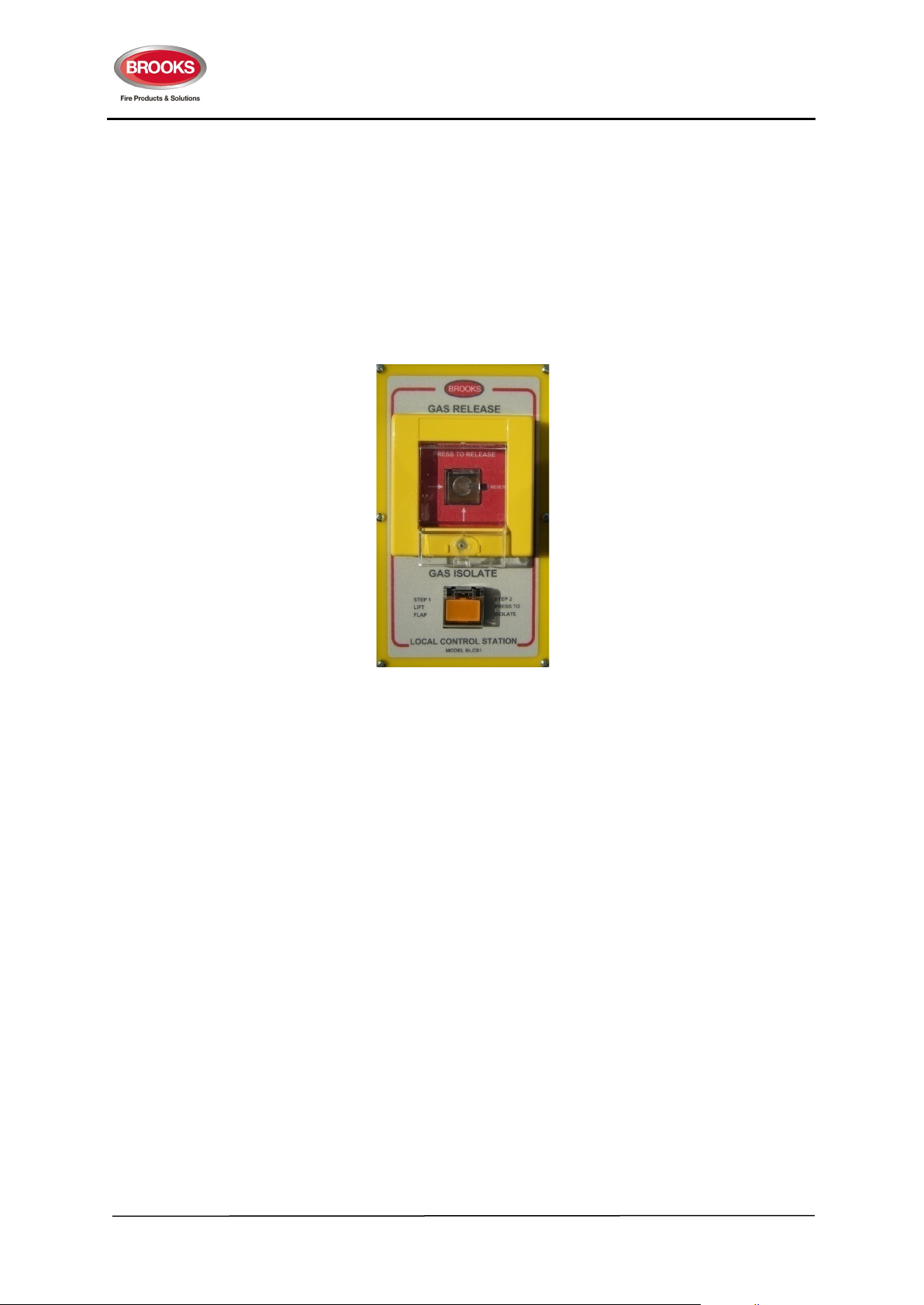
FT2GAS Gaseous Extinguishing System
Rev No. 1.3
† Countdown timer can be set between 0 and 95 seconds in 5 sec increments
†† At the end of the count down, a relay on the timer board activates for switching of external equipment
or any other application.
For more details, refer to technical datasheets TDS005, TDS025 and block wiring diagram shown in this
manual in Figure 20 page 56 and Figure 21 page 57.
4.9.3 Local Control Station BLC1
Figure 16 Local Control Station BLCS1
General
The Local Control Station (BLCS1) provides for the manual release and discharge inhibit of the gas
extinguishing agent.
BLCS1 is interfaced to Brooks FT2GAS control panel via a supervised 4 wire connection.
The GAS RELEASE function provides a manual initiate switch, incorporating a two-step action which
initiates the normal system discharge sequence including fire and evacuation alarms, time delays, and
equipment shutdowns and overrides the discharge inhibit switch. The operation of this switch has a
visual indication at both the LCS and FT2Gas panel
The GAS ISOLATE function provides a discharge inhibit switch that prevents automatic discharge of the
extinguishing agent; stops and resets the normal system actuation control sequence; but does not
override the operation of the manual initiate switch. The operation of this switch causes an audible and
visual indication at the LCS and a visual indication at the FT2GAS panel
The BLCS1 has been designed to be highly visible to the occupants when placed adjacent to the main
entry to the protected area.
Features
• Attractive design concept
• Built in audible warning for gas isolate
50
Page 51

FT2GAS Gaseous Extinguishing System
Rev No. 1.3
• Two steps operation for gas release prevents accidental operation
• Resettable gas release control
• 4 wire interface to the gas panel
• No current draw in quiescent state
• Designed to meet AS4214 for automatic control.
Operation
To release the gas:
1. Lift the flap of the gas release switch
2. Press the square switch in the centre of the housing. Once pressed, the gas control panel
activates the 24Vdc signal to gas actuators. The built in LED of the switch body illuminates.
Upon the completion of the gas release procedures, the release switch must be restored to normal. To
restore the switch, using a small screwdriver or a ball pen, press the “Reset” latch the switch body will
come forward.
To isolate the gas:
1. Lift the flap of the gas isolate switch
2. Press switch
The gas discharge will be inhibited, audible warning sounds and the LED in the switch body illuminates.
To reset lift flap and press switch once. Buzzer silences and led in switch body extinguishes.
4.9.4 24V Tone and Voice Sounders
General
The Brooks range of electronic sounders provide both tones and warning messages. The combination
of tone and voice message elicits a more positive response from building occupants during an
emergency. Tone only relies upon the occupant’s awareness of the tones meaning and purpose.
The Brooks electronic sounder consists of a speaker and digital voice/tone module which can be custom
programmed for tonal frequency, voice message and language to meet specific client needs.
Available Models
B24VSPS Surface Mount Speaker B24VSPF Flush Mount Speaker B24VH Surface Mount Horn Speaker
Figure 17 Brooks Electronic Sounders
51
Page 52

FT2GAS Gaseous Extinguishing System
Rev No. 1.3
Operation
The BROOKS electronic sounder has two inputs, typically used for Alert and Evacuation but may also
be two evacuation signals providing the same tone but differing language messages. The sounder
requires a 24Vdc signal applied at the appropriate polarity. When power is applied to the digital
voice/tone module the unit will sound the tone for approximately 10-12 seconds followed by a digital
voice message. The tone and message are repeated until power is shut off.
Selection of tones and messages, messages only, or tones only is available using Brooks’ Audio Utility
software.
There is a jumper for selection of Australian or New Zealand evacuation/alert tones.
Tones
The standard tones available:
For New Zealand AS2220.1 Alert tone
AS2220.1 Evacuate tone
For Australia ISO7731 Alert Tone
ISO 8201 Evacuate Tone (T3)
Voice messages
All models come pre-programmed with a default alert and evacuate message. The sounder is also
available with gas warning messages. Custom messages can be easily uploaded using software and
serial cable. For customised tones and voice messages contact your nearest Brooks office.
Connection
Horn Sounder: Flying leads are supplied for termination to a
24Vdc source. The message will switch between Alert/Evac
depending on the polarity of the supplied DC voltage.
Flush And Surface Mount Speaker Sounders: These can be
terminated directly to the screw terminals as shown circled in
the attached picture.
For Alert 1
st
Stage Message Terminate: 0Vdc to “1”
+24Vdc to “2”
For Evac 2nd Stage Message Terminate: +24Vdc to “1”
0Vdc to “2”
Note: The polarity of connected 24Vdc signal determines which tone/message is selected.
End of line devices
Turn on voltage is 14V. Below this voltage no current is drawn, this allows for the use of end of line
resistors for the supervision of the sounder circuit.
52
Page 53

FT2GAS Gaseous Extinguishing System
Voltage
24V (range 20-30Vdc)
<100mA (24Vdc; Australian evacuation tone)
Speaker
85dB (24Vdc; Australian evacuation tone)
Horn
100dB (24Vdc; Australian evacuation tone)
Voltage
24V
Rev No. 1.3
Specification
Current
<150mA (24Vdc; New Zealand evacuation tone)
Output
4.9.5 Gas Strobe Interface (SUB938)
The strobe interface module shown in Figure 18, is designed to interface Brooks warning sign output of
FT2GAS to a dual strobe e.g. amber / red combo.
Table 15 Gas Control board Connections page 32, terminal block TB3 explains the states for warning
signs.
The strobe module is connected to the same wiring used to connect the warning signs and provides two
outputs to drive amber strobe on first alarm (Level 1) and red strobe on second alarm (Level 2). This
module also provides an output to activate external buzzer as well as a mute function.
Specifications
Current (quiescent) 0mA
Current (alarm) 20mA
Wiring
Inputs:
- L1+ (Level 1 alarm)
+L2 - (Level 2 alarm)
The polarity of connection determines whether evacuation or alert mode is selected. A second set of
terminals is provided to continue the wiring to the next device.
Figure 18 Dual Strobe Driver Board SUB938
53
Page 54

FT2GAS Gaseous Extinguishing System
Sequence
−
Sequence
Rev No. 1.3
MUTE BUZZER / L1 STROBE terminal allows for connection of an external momentary switch, which
when activates will turn of the buzzer and the L1 strobe.
Outputs: (all outputs are 24Vdc)
1. Buzzer
2. L1 strobe (level 1)
3. L2 strobe (level 2)
Operation:
The polarity states sequence of the Gas Control board PCB Layout (SUB928) for the warning signs is
explained in Table 33.
Table 33 Polarity state sequence for Warning Signs
Monitoring L1 L2
+ +
−
≅6V ≅24V ≅24V
−
+
The required polarity states sequence for strobes is shown in Table 34. Note that the difference lies in
the polarity state change from Monitoring to Level 1 (L1). For strobes, the polarity and voltage change
immediately to -/+24V as on Table 34 while for warning signs, only the voltage changes as on Table 33.
This is the reason why the Gas Strobe Interface (Sub938) module is required.
Table 34 Required polarity state sequence for Strobes
Monitoring L1 L2
+
−
+
≅6V ≅24V ≅24V
−
+
−
Miscellaneous conditions:
L1: Alert strobe and buzzer are activated, can be de-activated by connecting a switch to the MUTE
BZZER L1 STROBE input.
L2: Evacuation strobe and buzzer are activated (and cannot be muted/turned off)
54
Page 55

FT2GAS Gaseous Extinguishing System
Rev No. 1.3
5. BLOCK WIRING DIAGRAM
Figure 19 FT2GAS Block Wiring Diagram
55
Page 56
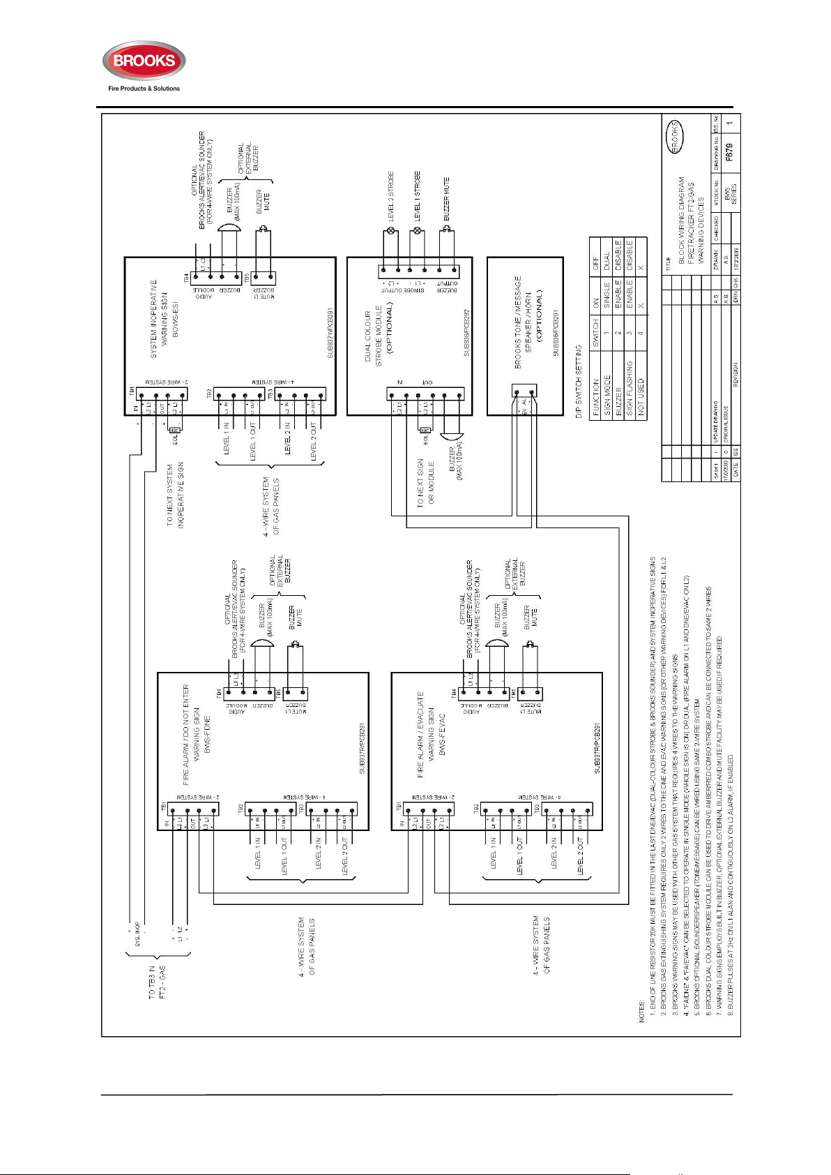
FT2GAS Gaseous Extinguishing System
Rev No. 1.3
Figure 20 FT2GAS Warning Signs Connection Diagram
56
Page 57

FT2GAS Gaseous Extinguishing System
Rev No. 1.3
Figure 21 Warning Sign with Voice and Timer connection
57
Page 58

FT2GAS Gaseous Extinguishing System
Rev No. 1.3
NSW - Head Office
P.O. Box 7050 Silverwater NSW 1811
4 Pike Street Rydalmere NSW 2116
Ph: 02 9684 1466
Website: www.Brooks.com.au
VIC
9/71 Victoria Crescent, Abbotsford VIC 3067
Ph: 03 9879 5294
SA
P.O. Box 101 Woodville SA 5011
729A Port Road, Woodville, SA 5011
Ph: 08 8347 0000
QLD
P.O. Box 511 Archerfield QLD 4108
2/49 Boyland Ave Coopers Plains, QLD 4108
Ph: 07 3373 8222
WA
P.O. Box 2114, Midland DC W.A. 6936
6/91 Leach Highway, Kewdale WA 6105
Ph: 08 6262 8095
Or National Australian Sales Number: 1300 78 FIRE (3473)
For the cost of local call.
58
 Loading...