

Page 1

On-Board® Cryopump
Installation and Maintenance Manual
8040491 Revision AB
Page 2

On-Board® Cryopump
Installation and Maintenance Manual
Information provided within this document is subject to change without notice, and although believed to be
accurate, Brooks Automation assumes no responsibility for any errors, omissions, or inaccuracies.
AcuLigner™, Align™, AquaTran™, AutoTeach™, ATR™, AXM™, Basic Blue™, BiSymmetrik™,
CenterSmart™, Cool Solutions™, Crate to Operate™, e-RMA™, e-Spares™, e-Volution™, FastRegen™,
FIXLOAD™, FrogLeg™, InLigner™, InCooler™, Interface™, Jet Engine™, LowProfile™, M2 Nano™,
Mini-Ion™, PASIV™, PowerPak™, PerformanceBlue™, PowerPak™, PowerTools™, QuadraFly™, Radius™,
Radient™, Radient Express™, Reliance™, Reliance ATR™, RetroEase™, SCARA™, SmartPM™,
SPOTLevel™, Synetics™, The New Pathway to Productivity™, Time Optimized Trajectory™, Time Optimal
Trajectory™, Time Optimized Path™, TopCooler™, TopLigner™, Ultimate Blue™, VAC-407™, VacuTran™,
Vacuum Quality Monitor™, VQM™, Vacuum Quality Index™, VQI™, and the Brooks logo are trademarks of
Brooks Automation, Inc.
AcuTran
Cryo-Torr
MagnaTran
On-Board
TurboPlus
®
, AquaTrap®, Conductron®, Convectron®, the Cool Solutions logo, Cryodyne®, Cryotiger®,
®
, Fusion®, GOLDLink®, Granville-Phillips®, Guardian®, GUTS®, Helix®, Jet®, Leapfrog®,
®
, MapTrak®, Marathon®, Marathon 2®, Marathon Express®, Micro-Ion®, MiniConvectron®,
®
, Polycold®, Razor®, Simplicity Solutions®, the Simplicity Solutions logo, Stabil-Ion®, TrueBlue®,
®
, Vision®, Zaris®, and the Brooks Automation logo are registered U.S. trademarks of Brooks
Automation, Inc.
All other trademarks are properties of their respective owners.
© 2013 Brooks Automation, Inc. All Rights Reserved. The information included in this manual is Proprietary
Information of Brooks Automation and is provided for th e use of Broo ks Automation customer s only and cann ot
be used for distribution, reproduction, or sale without the express written permission of Brooks Automation.
This information may be incorporated into the user’s documentation, however any changes made by the user
to this information is the responsibility of the user.
For Technical Support:
Location
North America
®
GUTS
Contact Number
+1-800-FOR-GUTS (1-800-367-4887)
+1-978-262-2900
Europe +49-1804-CALL-GUTS (+49-1804-2255-4887)
Japan +81-45-477-5980
China +86-21-5131-7066
Taiwan +886-3-5525225
Korea +82-31-288-2500
Singapore +65-6464-1481
Visit us online: www.brooks.com
January 11, 2013 Part Num 8040491 Revision AB
This technology is subject to United St ates export Administra tion Regu lations and aut horized to the d estination
only; diversion contrary to U.S. law is prohibited.
Printed in the U.S.A.
Brooks Automation
8040491 Revision AB
Page 3

Table of Contents
Table of Contents
List of Figures
List of Tables
Cryopump Safety
Hazard Alerts . . . . . . . . . . . . . . . . . . . . . . . . . . . . . . . . . . . . . . . . . . . . . . . . . . . . . . S-1
Safety Icons . . . . . . . . . . . . . . . . . . . . . . . . . . . . . . . . . . . . . . . . . . . . . . . . . . . . S-2
Signal Words . . . . . . . . . . . . . . . . . . . . . . . . . . . . . . . . . . . . . . . . . . . . . . . . . . . S-2
Safety Text . . . . . . . . . . . . . . . . . . . . . . . . . . . . . . . . . . . . . . . . . . . . . . . . . . . . . S-3
References . . . . . . . . . . . . . . . . . . . . . . . . . . . . . . . . . . . . . . . . . . . . . . . . . . . . . . . . S-3
Cryopump Hazards . . . . . . . . . . . . . . . . . . . . . . . . . . . . . . . . . . . . . . . . . . . . . . . . . S-4
Toxic, Corrosive, Dangerous Gases, or Liquids . . . . . . . . . . . . . . . . . . . . . . . . S-4
Flammable or Explosive Gases . . . . . . . . . . . . . . . . . . . . . . . . . . . . . . . . . . . . . S-5
Electric Shock . . . . . . . . . . . . . . . . . . . . . . . . . . . . . . . . . . . . . . . . . . . . . . . . . . S-5
High Gas Pressure . . . . . . . . . . . . . . . . . . . . . . . . . . . . . . . . . . . . . . . . . . . . . . . S-6
Regen Control Users Only . . . . . . . . . . . . . . . . . . . . . . . . . . . . . . . . . . . . . . . . . S-7
Cryopump Oxygen Procedures . . . . . . . . . . . . . . . . . . . . . . . . . . . . . . . . . . . . . S-8
Lifting Requirements . . . . . . . . . . . . . . . . . . . . . . . . . . . . . . . . . . . . . . . . . . . . . S-9
Section 1 - On-Board Cryopump Description
Introduction . . . . . . . . . . . . . . . . . . . . . . . . . . . . . . . . . . . . . . . . . . . . . . . . . . . . . . . 1-1
Installation, Operation, Troubleshooting, and Maintenance Procedures . . . . . . . . . 1-1
Microprocessor-Based Control System . . . . . . . . . . . . . . . . . . . . . . . . . . . . . . . . . . 1-1
Remote Operation Options . . . . . . . . . . . . . . . . . . . . . . . . . . . . . . . . . . . . . . . . 1-2
Specifications . . . . . . . . . . . . . . . . . . . . . . . . . . . . . . . . . . . . . . . . . . . . . . . . . . . . . . 1-6
Theory of Operation . . . . . . . . . . . . . . . . . . . . . . . . . . . . . . . . . . . . . . . . . . . . . . . . 1-19
Cold Head . . . . . . . . . . . . . . . . . . . . . . . . . . . . . . . . . . . . . . . . . . . . . . . . . . . . 1-19
Vacuum Vessel and Arrays . . . . . . . . . . . . . . . . . . . . . . . . . . . . . . . . . . . . . . . 1-19
Compressor Gas and Oil Flows . . . . . . . . . . . . . . . . . . . . . . . . . . . . . . . . . . . . 1-19
Section 2 - Installation
Introduction . . . . . . . . . . . . . . . . . . . . . . . . . . . . . . . . . . . . . . . . . . . . . . . . . . . . . . . 2-1
Keypad/Display Installation . . . . . . . . . . . . . . . . . . . . . . . . . . . . . . . . . . . . . . . . . . 2-2
Position A . . . . . . . . . . . . . . . . . . . . . . . . . . . . . . . . . . . . . . . . . . . . . . . . . . . . . 2-2
©2013 Brooks Automation Inc Part No. 8040491, Rev. AB, 01/11/2013 1-i
.
Page 4

Position B . . . . . . . . . . . . . . . . . . . . . . . . . . . . . . . . . . . . . . . . . . . . . . . . . . . . . . 2-3
Position C . . . . . . . . . . . . . . . . . . . . . . . . . . . . . . . . . . . . . . . . . . . . . . . . . . . . . . 2-4
Position D . . . . . . . . . . . . . . . . . . . . . . . . . . . . . . . . . . . . . . . . . . . . . . . . . . . . . 2-5
On-Board Cryopump Installation . . . . . . . . . . . . . . . . . . . . . . . . . . . . . . . . . . . . . . 2-6
On-Board 500 Cryopump Installation . . . . . . . . . . . . . . . . . . . . . . . . . . . . . . . . . . . 2-7
Vent Pipe Connection . . . . . . . . . . . . . . . . . . . . . . . . . . . . . . . . . . . . . . . . . . . . 2-9
Roughing Pump Connection . . . . . . . . . . . . . . . . . . . . . . . . . . . . . . . . . . . . . . 2-10
Rough Valve Gas Connection . . . . . . . . . . . . . . . . . . . . . . . . . . . . . . . . . . . . . 2-10
Purge Gas Connection . . . . . . . . . . . . . . . . . . . . . . . . . . . . . . . . . . . . . . . . . . . 2-10
Helium Line Connections . . . . . . . . . . . . . . . . . . . . . . . . . . . . . . . . . . . . . . . . 2-10
Auxiliary (AUX) TC Gauge Installation . . . . . . . . . . . . . . . . . . . . . . . . . . . . . 2-11
Setpoint Relays . . . . . . . . . . . . . . . . . . . . . . . . . . . . . . . . . . . . . . . . . . . . . . . . . . . 2-11
. . . . . . . . . . . . . . . . . . . . . . . . . . . . . . . . . . . . . . . . . . . . . . . . . . . . . . . . . . . . . . . . 2-12
Remote Keypad/Display Installation (Optional) . . . . . . . . . . . . . . . . . . . . . . . . . . 2-12
Section 3 - Troubleshooting
Technical Inquiries . . . . . . . . . . . . . . . . . . . . . . . . . . . . . . . . . . . . . . . . . . . . . . . . . 3-2
Section 4 - Maintenance
Helium Circuit Decontamination . . . . . . . . . . . . . . . . . . . . . . . . . . . . . . . . . . . . . . . 4-1
Background . . . . . . . . . . . . . . . . . . . . . . . . . . . . . . . . . . . . . . . . . . . . . . . . . . . . 4-2
Equipment/Tools Requirements . . . . . . . . . . . . . . . . . . . . . . . . . . . . . . . . . . . . 4-3
Method # 1 - Decontaminate all On-Board Cryopumps . . . . . . . . . . . . . . . . . . 4-6
Decontamination Alternatives . . . . . . . . . . . . . . . . . . . . . . . . . . . . . . . . . . . . . . . . 4-10
Method # 2 Decontamination of Only Cold Cryopumps . . . . . . . . . . . . . . . . 4-11
Step 1 - Method # 2. . . . . . . . . . . . . . . . . . . . . . . . . . . . . . . . . . . . . . . . . . . 4-11
Step 17 - Method # 2. . . . . . . . . . . . . . . . . . . . . . . . . . . . . . . . . . . . . . . . . . 4-11
Method # 3 Grouped Decontamination Using Manifold . . . . . . . . . . . . . . . . . 4-11
Step 5 - Method # 3. . . . . . . . . . . . . . . . . . . . . . . . . . . . . . . . . . . . . . . . . . . 4-12
Step 6 - Method # 3. . . . . . . . . . . . . . . . . . . . . . . . . . . . . . . . . . . . . . . . . . . 4-12
Step 10- Method # 3 . . . . . . . . . . . . . . . . . . . . . . . . . . . . . . . . . . . . . . . . . . 4-12
Steps 11 - 16 - Method # 3 . . . . . . . . . . . . . . . . . . . . . . . . . . . . . . . . . . . . . 4-12
On-Board Cryopump Cleaning . . . . . . . . . . . . . . . . . . . . . . . . . . . . . . . . . . . . . . . 4-15
Index
List of Figures
List of Tables
1-ii ©2013 Brooks Automation Inc Part No. 8040491, Rev. AB, 01/11/2013
Page 5

List of Figures
Figure 1-1: On-Board Cryopumps . . . . . . . . . . . . . . . . . . . . . . . . . . . . . . . . . . . . . . 1-3
Figure 1-2: On-Board Cryopumps . . . . . . . . . . . . . . . . . . . . . . . . . . . . . . . . . . . . . . 1-4
Figure 1-3: On-Board Cryopumps . . . . . . . . . . . . . . . . . . . . . . . . . . . . . . . . . . . . . . 1-5
Figure 1-4: Typical On-Board Cryopump System . . . . . . . . . . . . . . . . . . . . . . . . . 1-20
Figure 1-5: Cutaway View of a Typical Flat On-Board Cryopump Vessel . . . . . . 1-21
Figure 1-6: Cutaway View of a Typical Straight On-Board Cryopump Vessel. . . 1-22
Figure 1-7: Typical Flat On-Board Cryopump Component Identification. . . . . . . 1-23
Figure 1-8: Typical Straight On-Board Cryopump Component Identification . . . 1-24
Figure 2-1: Block Diagram for On-Board Cryopump Installation. . . . . . . . . . . . . . 2-1
Figure 2-2: Keypad/Display Mounting Position A. . . . . . . . . . . . . . . . . . . . . . . . . . 2-2
Figure 2-3: Keypad/Display Mounting Position B. . . . . . . . . . . . . . . . . . . . . . . . . . 2-3
Figure 2-4: Keypad/Display Mounting Position C. . . . . . . . . . . . . . . . . . . . . . . . . . 2-4
Figure 2-5: Keypad/Display Mounting Position D. . . . . . . . . . . . . . . . . . . . . . . . . . 2-5
Figure 2-6: Lifting Bars . . . . . . . . . . . . . . . . . . . . . . . . . . . . . . . . . . . . . . . . . . . . . . 2-7
Figure 2-7: Setpoint Relays Connection and Pin Identification . . . . . . . . . . . . . . . 2-12
Figure 4-1: Decontamination Flowchart. . . . . . . . . . . . . . . . . . . . . . . . . . . . . . . . . . 4-4
Figure 4-2: On-Board Cryopump Helium Supply and Return Lines . . . . . . . . . . . . 4-8
Figure 4-3: Maintenance Manifold Part Number 8032051G001 . . . . . . . . . . . . . . 4-13
Figure 4-4: Proper Helium Line Coupling Disconnection/Connection . . . . . . . . . 4-14
©2013 Brooks Automation Inc Part No. 8040491, Rev. AB, 01/11/2013 1-iii
.
Page 6

This Page Intentionally Left Blank
1-iv ©2013 Brooks Automation Inc Part No. 8040491, Rev. AB, 01/11/2013
Page 7

List of Tables
Table 1-1: On-Board 4 Cryopump Specifications ..................................................................... 1-6
Table 1-2: On-Board 4F Cryopump Specifications ................................................................... 1-7
Table 1-3: On-Board 6 Cryopump Specifications ..................................................................... 1-8
Table 1-4: On-Board 8 Cryopump Specifications ..................................................................... 1-9
Table 1-5: On-Board 8F Cryopump Specifications ................................................................. 1-10
Table 1-6: On-Board Enchanced 8F Cryopump Specifications .............................................. 1-11
Table 1-7: On-Board 10 Cryopump Specifications ................................................................. 1-12
Table 1-8: On-Board 10F Cryopump Specifications ............................................................... 1-13
Table 1-9: On-Board 250F Cryopump Specifications .............................................................1-14
Table 1-10: On-Board 250FH Cryopump Specifications ........................................................ 1-15
Table 1-11: On-Board 400 Standard Capacity Cryopump Specifications ............................... 1-16
Table 1-12: On-Board 400 High Capacity Cryopump Specifications ..................................... 1-17
Table 1-13: On-Board 500 ISO-K Cryopump Specifications ................................................. 1-18
Table 3-1: Cryopump Troubleshooting Procedures ................................................................... 3-2
Table 3-1: Troubleshooting Procedures (continued) ................................................................. 3-3
Table 4-1: Methods of Decontamination ................................................................................... 4-1
Table 4-2: Decontamination Tools and Equipment ................................................................... 4-3
©2013 Brooks Automation Inc Part No. 8040491, Rev. AB, 01/11/2013 1-v
.
Page 8

This Page Intentionally Left Blank
1-vi ©2013 Brooks Automation Inc Part No. 8040491, Rev. AB, 01/11/2013
Page 9
Introduction
All On-Board®, On-Board® IS, and Cryo-Torr® products are designed to provide
extremely safe and dependable operation when properly used. This chapter
describes safety hazard alerts used throughout this manual for the Brooks Automation cryopumps.
All personnel involved in the installation, operation, or maintenance of OnBoard
ments presented in this manual, along with all safety requirements for the facility
where the pump is installed, and all applicable national and international safety
requirements.
Refer to Contacting Brooks’ Technical Support at the front of this manual, or call
your local Customer Support Center, for further assistance.
Hazard Alerts
The On-Board Cryopump Installation and Maintenance Instructions use industry standard hazard alerts to make you aware of hazardous conditions. Alerts are
composed of three elements:
Cryopump Safety
®
, On-Board® IS, and Cryo-Torr® products must follow the safety require-
• Safety Icon(s)
•Signal Word
• Safety Text
Following is an example of a typical hazard alert, with safety icons, signal word,
and text.
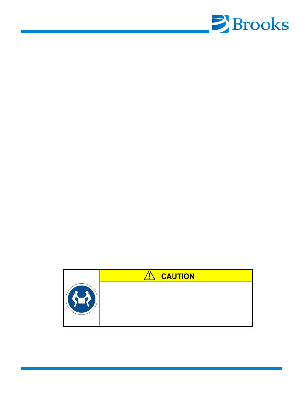
Two-Person Lift Required
This pump weighs ____kilos/lbs.
Lifting heavy loads can result in serious injury.
Use a 2-person lift or a lifting aid when attempting to lift
this pump.
©2013 Brooks Automation Inc Part No. 8040491, Rev. AB, 01/11/2013 S-1
.
Page 10
Safety Icons
Hazard alerts indicating a caution, warning, or danger to personnel contain Safety
Icons that graphically identify the hazard involved.
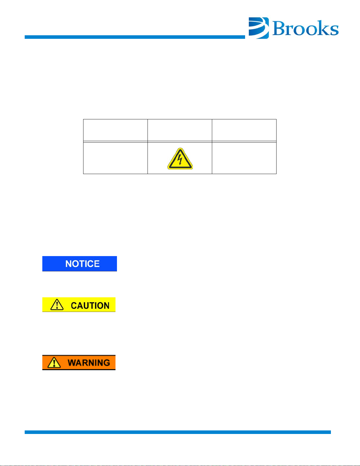
Table S-1 illustrates the meaning of a typical safety icon.
Table S-1: Safety Icons
Associated Signal
Caution, Warning or
Danger
The safety icons in this manual conform to ISO 3864 and ANSI Z535 standards.
Signal Words
All hazard alerts contain signal words that call attention to safety messages and
designate the degree of hazard seriousness. The signal words used in this manual
are Notice, Caution, Warning, and Danger. The meaning and formatting of each
of these signal words follows.
Notice indicates a situation or unsafe practice which, if not avoided, may result in
equipment damage. The Notice signal word is highlighted in blue.
Word
Icon Indication
Indicates an electric
shock hazard.
Caution indicates a potentially hazardous situation or unsafe practice which, if
not avoided, may result in minor or moderate personal injury. The Caution signal
word is preceded by an iconic exclamation point, indicating additional information is in the manual, and it is highlighted in yellow.
Warning indicates a potentially hazardous situation which, if not avoided, could
result in serious injury or death. The Warning signal word is preceded by an
iconic exclamation point, indicating additional information is in the manual, and
it is highlighted in orange.
S-2 ©2013 Brooks Automation Inc Part No. 8040491, Rev. AB, 01/11/2013
Page 11
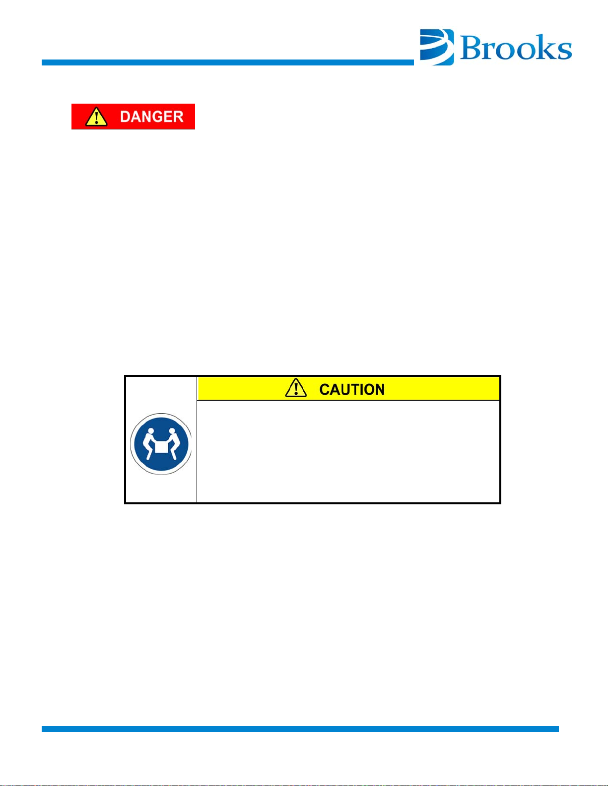
Danger indicates a potentially hazardous situation which, if not avoided, will
result in serious injury or death. The Danger signal word is preceded by an iconic
exclamation point, indicating additional information is in the manual, and it is
highlighted in red.
Safety Text
Hazard alert text follows a standard three-part format:
The order of hazard alert text is fixed.
The example below illustrates typical hazard alert text, presented in the correct
order.
• identify the hazard,
• state the consequences if the hazard is not avoided,
• state how to avoid the hazard.
References
Two-Person Lift Required
This cryopump is heavy. Refer to the specifications of
your pump for the weight.
Lifting heavy loads can result in serious injury.
Use a 2-person lift or a lifting aid when attempting to lift
this pump.
For more information about safety standards, refer to the following documents.
• ISO 3864-2: 2004 Graphical Symbols - Safety Colors and
Safety Signs - Part 2: Design principles for product safety
labels.
• ANSI Z535.4 Standard for Product Safety Signs and Labels
©2013 Brooks Automation Inc Part No. 8040491, Rev. AB, 01/11/2013 S-3
.
Page 12
Cryopump Hazards
Observe the following safety precautions when installing, operating, troubleshooting, and maintaining the On-Board
ment. If you have any doubts on using this equipment, refer to Contacting Brooks’
Technical Support at the beginning of this manual.
Always follow all local, state, and national codes, as well as site-specific codes,
when working with toxic/corrosive gases or liquids, flammable or explosive
gases, and/or high voltage.
The following hazard alerts appear on the pump, in this manual, or both.
Toxic, Corrosive, Dangerous Gases, or Liquids
®
, On-Board IS and Cryo-Torr® equip-
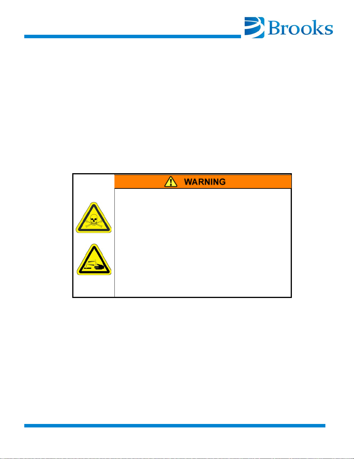
Toxic/Corrosive Gases
Toxic and/or corrosive process gases or liquids
pumped or captured by an On-Board, On-Board IS, or
Cryo-Torr product could cause severe injury on contact.
Always vent toxic/corrosive gases or liquids to a safe
location using an inert purge gas.
The customer is responsible for safely exhausting
these gases.
Clearly identify on the cryopump which toxic/corrosive
gas or liquid is contained in the pump before storing or
shipping it to Brooks Automation.
S-4 ©2013 Brooks Automation Inc Part No. 8040491, Rev. AB, 01/11/2013
Page 13
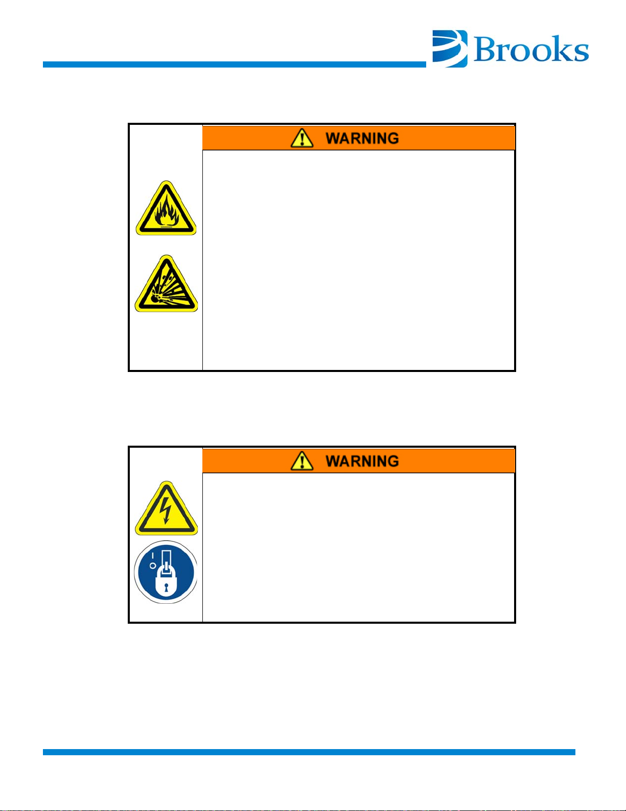
Flammable or Explosive Gases
Flammable or explosive gases captured by an OnBoard, On-Board IS, or Cryo-Torr pump can cause
severe injury if ignited.
Always purge the cryopump with an inert gas during
regeneration.
Always vent flammable or explosive gases to a safe
location using an inert purge gas. Purging the
cryopump’s exhaust line might also be necessary.
The customer is responsible for safely exhausting
these gases.
Do not install a hot filament type vacuum gauge on the
high vacuum side of the isolation valve. This could be
an ignition source for flammable gases in the product.
Flammable/Explosive Gases
Electric Shock
Electric Shock
Electric shock can cause severe injury or death.
Disconnect the high vacuum pump system from all
power sources before making electrical connections
between system components or before performing
troubleshooting and maintenance procedures.
Perform Lockout/Tagout as required by the facility
where the equipment is installed.
©2013 Brooks Automation Inc Part No. 8040491, Rev. AB, 01/11/2013 S-5
.
Page 14
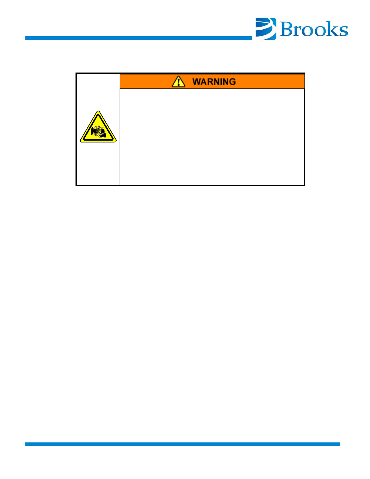
High Gas Pressure
Take the following precautions when working with high gas pressure:
1. Normal making and breaking of the quick disconnect couplings can be done routinely. However, when a quick disconnect coupling needs to be replaced and separated from the
helium flex or solid line, always bleed the helium charge down
to atmospheric pressure before any disassembly.
2. During regeneration, a rapid expansion of the cryopumped species
occurs within the cryopump. Restricting the flow through the
exhaust port and exhaust line rapidly increases the pressure in the
cryopump. This high internal pressure can cause severe injury
from propelled particles or parts.
High Gas Pressure
High helium gas pressure is present in the cryogenic
system and high pressure gas can be present within
the cryopump. These high pressure gases can cause
severe injury from propelled particles or parts.
Do not modify or remove any pressure relief valve on
the cryopump.
Ensure that the path for the regenerated gas is
unobstructed.
S-6 ©2013 Brooks Automation Inc Part No. 8040491, Rev. AB, 01/11/2013
Page 15
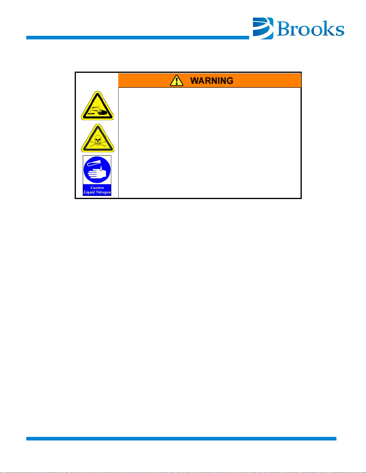
Regen Control Users Only
During regeneration, cold gases vent through the
roughing valve and roughing line and into the roughing
pump. These gases can cause severe injury.
Avoid contact with liquid nitrogen to exposed skin.
Ensure the roughing systems are compatible with
these gases.
Take the following precautions when installing the gas handling system, including roughing pump for toxic, corrosive, or dangerous gases.
• The roughing pump must be compatible with these gases
Dangerous Gases
• The discharge from the roughing pump may include these
gases and should be vented in a safe manner
1. Use appropriately sized roughing lines to prevent over pressurization of the roughing line during the expansion of such
gases
2. Be sure that the roughing line is compatible with low temperatures
3. Use roughing lines of sufficient length to allow the gases to warm
adequately before entering the roughing pump
4. Do not use fast regeneration after pumping large amounts of oxygen unless the roughing system is compatible with oxygen duty
©2013 Brooks Automation Inc Part No. 8040491, Rev. AB, 01/11/2013 S-7
.
Page 16
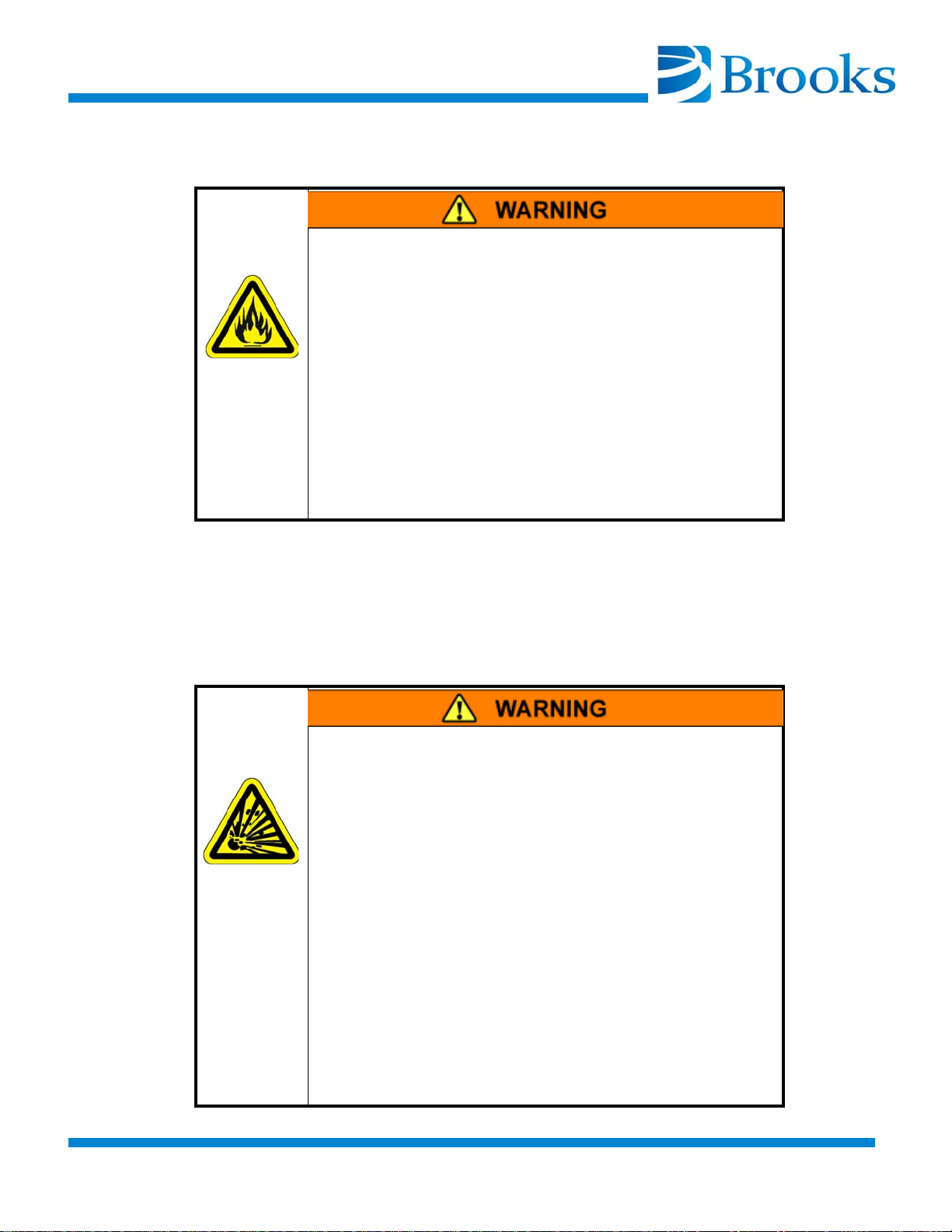
Cryopump Oxygen Procedures
Combustion resulting from oxygen used as a process
gas can cause severe injury.
1. Ensure that there are no sources of ignition, such as
hot filament vacuum gauges, on the cryopump side of
the high vacuum valve operating during the warming or
venting of the cryopump.
2. Perform inert gas purge regeneration cycles at flow
rates recommended for cryopumps.
3. Regenerate as frequently as practical to minimize
the amount of oxidizer present in the cryopump.
Standard practice in the vacuum industry is that any system exposed to richerthan-air oxygen levels should be prepared for oxygen service per the manufacturer’s recommendations. This includes the use of oxygen service lubrication oils
in roughing pumps or dry roughing pumps.
Oxygen Combustion Hazard
Explosion Hazard
Explosion occurring from ozone in the cryopump can
cause severe injury. Ozone can be an unforesen byproduct of oxygen processes.
1. Reduce the oxygen flow rate to the lowest level that
the process allows.
2. Shorten the time between regenerations. Daily
regenerations may be required. Contact Brooks
Automation Technical Support for assistance.
3. Ensure that there are no sources of ignition (for
example, hot filament vacuum gauges) on the
cryopump side of the high vacuum valve operating
during the warming or venting of the cryopump
4. Perform inert gas purge regenerations at flow rates
recommended for cryopumps.
S-8 ©2013 Brooks Automation Inc Part No. 8040491, Rev. AB, 01/11/2013
Page 17
Signs of ozone presence are the following:
1. Crackling, popping sounds, as in electrical arcing, occurring within
the first few minutes of a regeneration cycle;
2. Gas venting from the cryopump during regeneration that has a pungent
smell similar to that present in an arc welding operation or after an elec
trical storm.
NOTE: A change in process can increase the amount of ozone present.
Lifting Requirements
This cryopump is heavy. Refer to the specifications of
your pump for the weight.
Lifting heavy loads can result in serious injury.
Use a 2-person lift or a lifting aid when attempting to lift
this pump.
-
Two-Person Lift Required
Lifting Aid Required
This cryopump is heavy. Refer to the specifications of
your pump for the weight.
Lifting heavy loads can result in serious injury.
Always use a lifting aid when attempting to lift this
pump.
©2013 Brooks Automation Inc Part No. 8040491, Rev. AB, 01/11/2013 S-9
.
Page 18

This Page Intentionally Left Blank
S-10 ©2013 Brooks Automation Inc Part No. 8040491, Rev. AB, 01/11/2013
Page 19

Section 1 - On-Board Cryopump Descrip-
tion
Introduction
This product is intended for use by industrial customers and should be serviced
only by Brooks or Brooks trained representatives. The service manuals and
related materials are provided in English at no charge and are intended for use by
experienced technicans. It is the responsibility of the user to obtain and assure the
accuracy of any needed translations of manuals. If you require assistance please
contact Brooks service department. Contact information can be found at www.brooks.com.
On-Board Cryopumps provide fast, clean pumping of all gases in the 10
Torr range. An On-Board Cryopump operates on the principle that gases can be
condensed and held at extremely low vapor pressures, achieving high speeds and
throughputs as described in Table 1-1 through Table 1-13.
The On-Board Cryopump is a highly-reliable and rugged unit that requires little
maintenance. Since the On-Board Cryopump exposes no moving parts, operating
fluids, or backing pumps to the vacuum, the possibility of system or process contamination from the On-Board Cryopump is eliminated.
-3
to 10-9
Installation, Operation, Troubleshooting, and Maintenance Procedures
All personnel responsible for installing, operating, troubleshooting, or maintaining an On-Board Crypump should become familiar with these procedures before
attempting to perform them.
Refer to the Installation/Interface drawing for the cryopump being installed for
specific pump layout and component information.
Microprocessor-Based Control System
The On-Board Cryopump is equipped with a microprocessor-based control system that allows you to monitor and control a wide range of vacuum system functions, such as cooldown, warm-up, and regeneration. Operations are performed
on a keypad control/display panel mounted on the cryopump.
Refer to the On-Board Cryopump Module Programming and Operation Instruc-
tions (8040410) that came with your On-Board Cryopump for a complete description of the operational functions available.
© 2013 Brooks Automation Inc Part No. 8040491, Rev. AB, 01/11/2013 1-1-1
.
Page 20

Remote Operation Options
A remote keypad/display that provides the same functions as the basic On-Board
keypad/display is available.
On-Board Cryopumps can be controlled remotely using either a BITBUS™ or RS232 protocol. The most common implementation, used in multiple On-Board
Cryopump process tools, is to network the On-Board Cryopumps using the BITBUS™ protocol. In this configuration, the networked On-Board Cryopumps are
managed as a group by the On-Board Network Terminal, which coordinates
group regeneration cycles and provides a standardized communication link to the
process tool host controller. Using this approach, control of the networked OnBoard Cryopumps is fully integrated with process tool control.
On-Board Cryopumps are available in the range of sizes and configurations
shown in Figure 1-1, Figure 1-2, and Figure 1-3. The specifications for each OnBoard Cryopump are provided in Table 1-1 through Table 1-13.
1-1-2 © 2013 Brooks Automation Inc Part No. 8040491, Rev. AB, 01/11/2013
Page 21
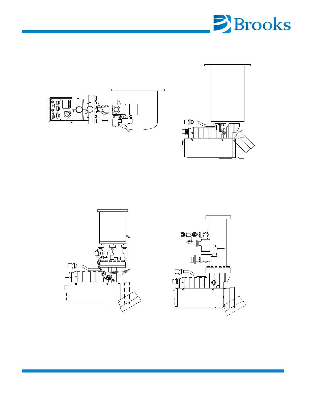
On-Board 8
On-Board 8F
On-Board 4
On-Board 6
Figure 1-1: On-Board Cryopumps
© 2013 Brooks Automation Inc Part No. 8040491, Rev. AB, 01/11/2013 1-1-3
.
Page 22
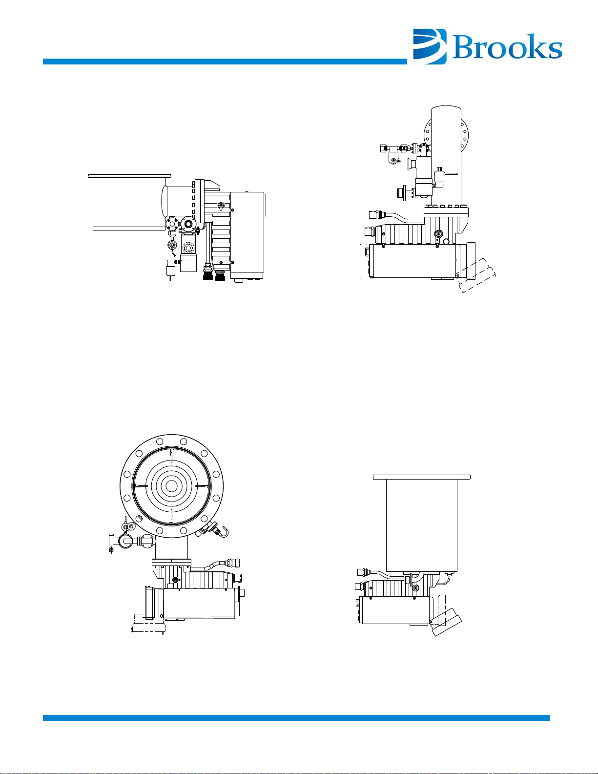
On-Board 4F
On-Board 250F
On-Board 10F
On-Board 10
Figure 1-2: On-Board Cryopumps
1-1-4 © 2013 Brooks Automation Inc Part No. 8040491, Rev. AB, 01/11/2013
Page 23
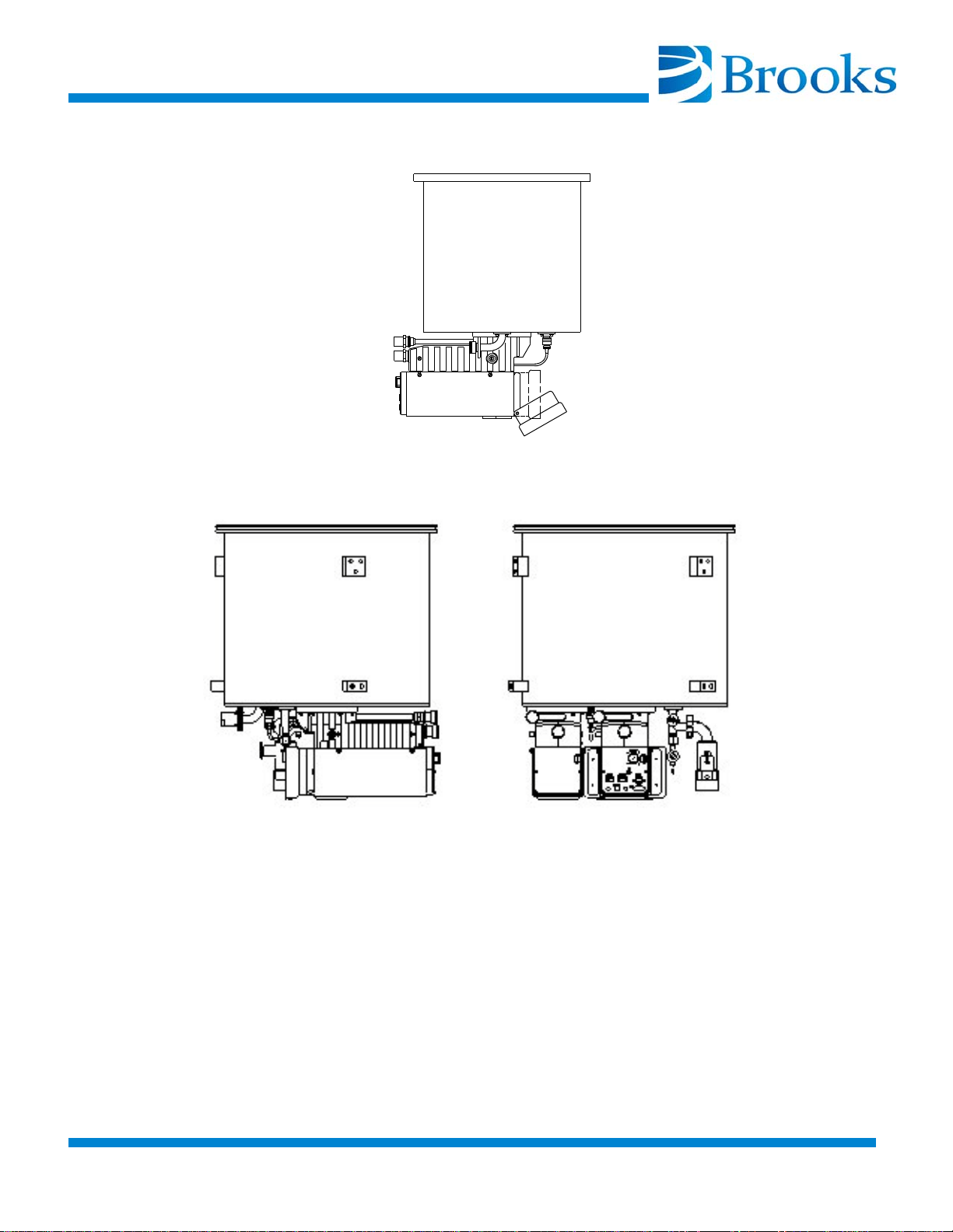
On-Board 500
On-Board 400
Figure 1-3: On-Board Cryopumps
© 2013 Brooks Automation Inc Part No. 8040491, Rev. AB, 01/11/2013 1-1-5
.
Page 24

Specifications
Parameter Specifications
Table 1-1: On-Board 4 Cryopump Specifications
Rough Pump Connec-
NW 25 ISO KF
tion
Integrated Hardware Keypad/Display (Optional)
Roughing Valve
Purge Valve
Cryopump TC Gauge
1st Stage Diode
2nd Stage Diode
1st Stage Heater
2nd Stage Heater
2 Setpoint Relays
RS-232 Interface
Pumping Speeds:
Water
Air
Hydrogen
Argon
1100 liters/sec
500 liters/sec
500 liters/sec
420 liters/sec
Argon Throughput 700 scc (9 Torr-liters/sec)
Capacity:
Argon
Hydrogen
210 std. liters (no recovery metric)
-7
100 std. liters (recovery to 10
in 30 sec. or
less)
3 std. liters @ 5 x 10
-6
Torr
Crossover 100 Torr-liters
Regeneration Time
Full (Typical)
Fast (Typical)
Less than 84 minutes
Less than 42 minutes
Dimensions Refer to Installation/Interface Drawing
Weight 45 lbs. (20 kg)
1-1-6 © 2013 Brooks Automation Inc Part No. 8040491, Rev. AB, 01/11/2013
Page 25

Table 1-2: On-Board 4F Cryopump Specifications
Parameter Specifications
Rough Pump Connec-
NW 25 ISO KF
tion
Integrated Hardware Keypad/Display (Optional)
Roughing Valve
Purge Valve
Cryopump TC Gauge
1st Stage Diode
2nd Stage Diode
1st Stage Heater
2nd Stage Heater
2 Setpoint Relays
RS-232 Interface
Pumping Speeds:
Water
Air
Hydrogen
Argon
1100 liters/sec
370 liters/sec
370 liters/sec
310 liters/sec
Argon Throughput 700 scc (9 Torr-liters/sec)
Capacity:
Argon
210 std. liters (no recovery metric)
100 std. liters (recovery to 10-7 @ 30 sec. or
Hydrogen
less)
3 std. liters @ 5 x 10⁻⁶ Torr
Crossover 100 Torr-liters
Regeneration Time
Full (Typical)
Fast (Typical)
Less than 84 minutes
Less than 42 minutes
Dimensions Refer to Installation/Interface Drawing
Weight 47 lbs. (21 kg)
© 2013 Brooks Automation Inc Part No. 8040491, Rev. AB, 01/11/2013 1-1-7
.
Page 26
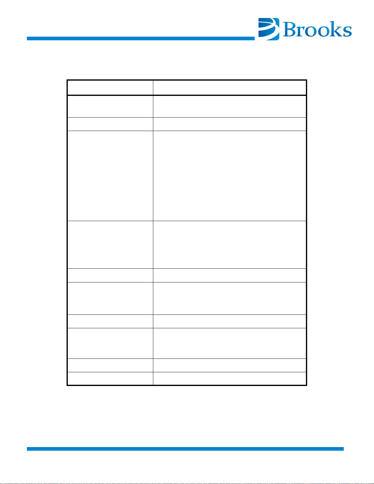
Table 1-3: On-Board 6 Cryopump Specifications
Parameter Specifications
Rough Pump Connec-
NW 25 ISO KF
tion
Purge Gas Connection VCR-4 Female Nut
Integrated Hardware Keypad/Display (Optional)
Roughing Valve
Purge Valve
Cryopump TC Gauge
1st Stage Diode
2nd Stage Diode
1st Stage Heater
2nd Stage Heater
2 Setpoint Relays
RS-232 Interface
Pumping Speeds:
Water
Air
Hydrogen
Argon
2,500 liters/sec
800 liters/sec
1,200 liters/sec
650 liters/sec
Argon Throughput 700 sccm (9 Torr-liters/sec)
Capacity:
Argon
Hydrogen
500 std. liters
9 std. liters @ 5 x 10
-6
Torr
Crossover 100 Torr-liters
Regeneration Time
Full (Typical)
Fast (Typical)
Less than 162 minutes
Less than 60 minutes
Dimensions Refer to Installation/Interface Drawing
Weight 55 lbs. (25 kg)
1-1-8 © 2013 Brooks Automation Inc Part No. 8040491, Rev. AB, 01/11/2013
Page 27

Table 1-4: On-Board 8 Cryopump Specifications
Parameter Specifications
Rough Pump Connec-
NW 25 ISO KF
tion
Integrated Hardware Keypad/Display (optional)
Roughing Valve
Purge Valve
Cryopump TC Gauge
1st Stage Diode
2nd Stage Diode
1st Stage Heater
2nd Stage Heater
2 Setpoint Relays
RS-232 Interface
Pumping Speeds:
Water
Air
Hydrogen
Argon
4000 liters/sec
1500 liters/sec
2500 liters/sec
1200 liters/sec
Argon Throughput 700 sccm (9 Torr-liters/sec)
Capacity:
Argon
Hydrogen
1000 std. liters
17 std. liters @ 5 x 10
-6
Torr
Crossover 150 Torr-liters
Regeneration Time
Full (Typical)
Fast (Typical)
Less than 162 minutes
Less than 60 minutes
Dimensions Refer to Installation/Interface Drawing
Weight 55 lbs. (25 kg)
© 2013 Brooks Automation Inc Part No. 8040491, Rev. AB, 01/11/2013 1-1-9
.
Page 28
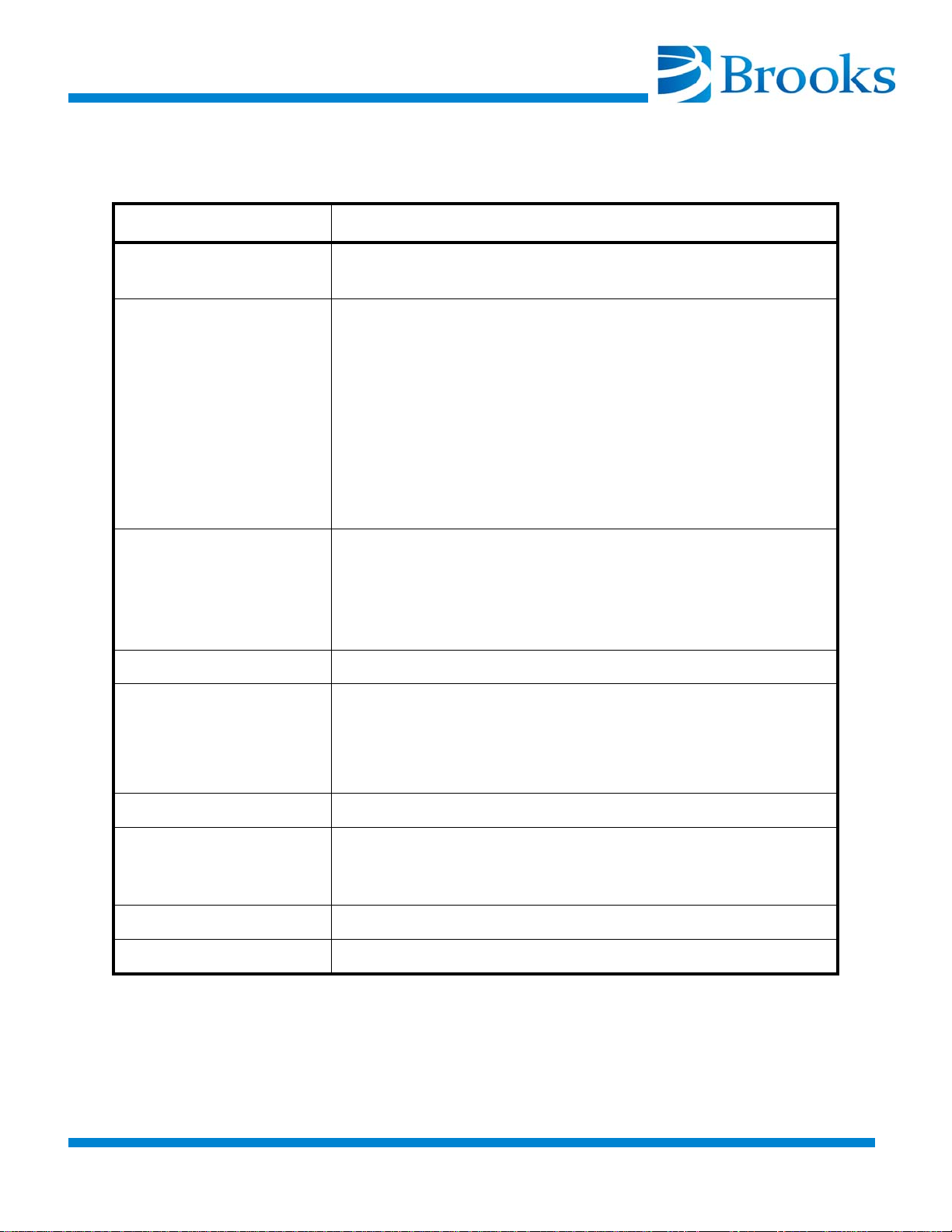
Table 1-5: On-Board 8F Cryopump Specifications
Parameter Specifications
Rough Pump Connec-
NW 25 ISO KF
tion
Integrated Hardware Keypad/Display (optional)
Roughing Valve
Purge Valve
Cryopump TC Gauge
1st Stage Diode
2nd Stage Diode
1st Stage Heater
2nd Stage Heater
2 Setpoint Relays
RS-232 Interface
Pumping Speeds:
Water
Air
Hydrogen
Argon
4000 liters/sec
1500 liters/sec
2200 liters/sec
1200 liters/sec
Argon Throughput 700 sccm (9 Torr-liters/sec)
Capacity:
Argon
1000 std. liters (no recovery metric)
450 std. liters (recovery to 10
Hydrogen
12 std. liters @ 5 x 10
-6
Torr
-7
in 30 seconds or less)
Crossover 150 Torr-liters
Regeneration Time
Full (Typical)
Fast (Typical)
Less than 162 minutes
Less than 60 minutes
Dimensions Refer to Installation/Interface Drawing
Weight 52 lbs. (24 kg)
1-1-10 © 2013 Brooks Automation Inc Part No. 8040491, Rev. AB, 01/11/2013
Page 29

Table 1-6: On-Board Enchanced 8F Cryopump Specifications
Parameter Specifications
Rough Pump Connec-
NW 25 ISO KF
tion
Integrated Hardware Keypad/Display (optional)
Roughing Valve
Purge Valve
Cryopump TC Gauge
1st Stage Diode
2nd Stage Diode
1st Stage Heater
2nd Stage Heater
2 Setpoint Relays
RS-232 Interface
Pumping Speeds:
Water
Air
Hydrogen
Argon
4000 liters/sec
1500 liters/sec
2200 liters/sec
1200 liters/sec
Argon Throughput 700 sccm (9 Torr-liters/sec)
Capacity:
Argon
1000 std. liters (no recovery metric)
750 std. liters (recovery to 10
Hydrogen
12 std. liters @ 5 x 10
-6
Torr
-7
in 30 seconds or less)
Crossover 150 Torr-liters
Regeneration Time
Full (Typical)
Fast (Typical)
Less than 162 minutes
Less than 60 minutes
Dimensions Refer to Installation/Interface Drawing
Weight 52 lbs. (24 kg)
© 2013 Brooks Automation Inc Part No. 8040491, Rev. AB, 01/11/2013 1-1-11
.
Page 30

Table 1-7: On-Board 10 Cryopump Specifications
Parameter Specifications
Rough Pump Connec-
NW 25 ISO KF
tion
Integrated Hardware Keypad/Display (optional)
Roughing Valve
Purge Valve
Cryopump TC Gauge
1st Stage Diode
2nd Stage Diode
1st Stage Heater
2nd Stage Heater
2 Setpoint Relays
RS-232 Interface
Pumping Speeds:
Water
Air
Hydrogen
Argon
9000 liters/sec
3000 liters/sec
5000 liters/sec
2500 liters/sec
Argon Throughput 1500 scc/min. (19 Torr-liters/sec)
Capacity:
Argon
Hydrogen
2000 std. liters
24 std. liters @ 5 x 10⁻⁶ Torr
Crossover 300 Torr-liters
Regeneration Time
Full (Typical)
Fast (Typical)
Less than 132 minutes
Less than 60 minutes
Dimensions Refer to Installation/Interface Drawing
Weight 95 lbs. (43 kg)
1-1-12 © 2013 Brooks Automation Inc Part No. 8040491, Rev. AB, 01/11/2013
Page 31

Table 1-8: On-Board 10F Cryopump Specifications
Parameter Specifications
Rough Pump Connec-
NW 25 ISO KF
tion
Integrated Hardware Keypad/Display (optional)
Roughing Valve
Purge Valve
Cryopump TC Gauge
1st Stage Diode
2nd Stage Diode
1st Stage Heater
2nd Stage Heater
2 Setpoint Relays
RS-232 Interface
Pumping Speeds:
Water
Air
Hydrogen
Argon
9500 liters/sec
3600 liters/sec
6000 liters/sec
3000 liters/sec
Argon Throughput 1500 scc/min. (19 Torr-liters/sec)
Capacity:
Argon
Hydrogen
2000 std. liters
24 std. liters @ 5 x 10⁻⁶ Torr
Crossover 300 Torr-liters
Regeneration Time
Full (Typical)
Fast (Typical)
Less than 132 minutes
Less than 60 minutes
Dimensions Refer to Installation/Interface Drawing
Weight 100 lbs. (45 kg)
© 2013 Brooks Automation Inc Part No. 8040491, Rev. AB, 01/11/2013 1-1-13
.
Page 32

Table 1-9: On-Board 250F Cryopump Specifications
Parameter Specifications
Rough Pump Connec-
NW 25 ISO KF
tion
Integrated Hardware Keypad/Display (optional)
Roughing Valve
Purge Valve
Cryopump TC Gauge
1st Stage Diode
2nd Stage Diode
1st Stage Heater
2nd Stage Heater
2 Setpoint Relays
RS-232 Interface
Pumping Speeds:
Water
Air
Hydrogen
Argon
6500 liters/sec
2200 liters/sec
3200 liters/sec
1800 liters/sec
Argon Throughput 700 sccm (9 Torr-liters/sec)
Capacity:
Argon
Hydrogen
1000 std. liters
16 std. liters @ 5 x 10
-6
Torr
Crossover 150 Torr-liters
Regeneration Time
Full (Typical)
Fast (Typical)
Less than 198 minutes
Less than 90 minutes
Dimensions Refer to Installation/Interface Drawing
Weight 58 lbs. (26 kg)
1-1-14 © 2013 Brooks Automation Inc Part No. 8040491, Rev. AB, 01/11/2013
Page 33

Table 1-10: On-Board 250FH Cryopump Specifications
Parameter Specifications
Rough Pump Connec-
NW 25 ISO KF
tion
Integrated Hardware Keypad/Display (optional)
Roughing Valve
Purge Valve
Cryopump TC Gauge
1st Stage Diode
2nd Stage Diode
1st Stage Heater
2nd Stage Heater
2 Setpoint Relays
RS-232 Interface
Pumping Speeds:
Water
Air
Hydrogen
Argon
6500 liters/sec
2200 liters/sec
4500 liters/sec
1800 liters/sec
Argon Throughput 700 sccm (9 Torr-liters/sec)
Capacity:
Argon
Hydrogen
1000 std. liters
24 std. liters @ 5 x 10
-6
Torr
Crossover 150 Torr-liters
Regeneration Time
Full (Typical)
Fast (Typical)
Less than 198 minutes
Less than 90 minutes
Dimensions Refer to Installation/Interface Drawing
Weight 58 lbs. (26 kg)
© 2013 Brooks Automation Inc Part No. 8040491, Rev. AB, 01/11/2013 1-1-15
.
Page 34

Table 1-11: On-Board 400 Standard Capacity Cryopump Specifications
Parameter Specifications
Rough Pump Connection NW 25 ISO KF
Integrated Hardware Keypad/Display (optional)
Roughing Valve
Purge Valve
Cryopump TC Gauge
1st Stage Diode
2nd Stage Diode
2nd Stage Heater
2 Setpoint Relays
RS-232 Interface
Pumping Speeds:
Water
Air
Hydrogen
Argon
16,000 liters/sec
6,000 liters/sec
5,000 liters/sec
5,000 liters/sec
Argon Throughput 500 scc/min (6 Torr-liters/sec)
Capacity
Argon
Hydrogen
2500 std. liters
15 std. liters @ 5 x 10
-6
Torr
Crossover 300 Torr-liters
Regeneration Time
Full (Typical)
Fast (Typical)
Less than 228 minutes
Less than 96 minutes
Dimensions Refer to Installation/Interface Drawing
Weight 170 lbs. (77 kg)
1-1-16 © 2013 Brooks Automation Inc Part No. 8040491, Rev. AB, 01/11/2013
Page 35

Table 1-12: On-Board 400 High Capacity Cryopump Specifications
Parameter Specifications
Rough Pump Connection NW 25 ISO KF
Integrated Hardware Keypad/Display (optional)
Roughing Valve
Purge Valve
Cryopump TC Gauge
1st Stage Diode
2nd Stage Diode
2nd Stage Heater
2 Setpoint Relays
RS-232 Interface
Pumping Speeds:
Water
Air
Hydrogen
Argon
16,000 liters/sec
6,000 liters/sec
12,000 liters/sec
5,000 liters/sec
Argon Throughput 500 scc/min (6 Torr-liters/sec)
Capacity
Argon
Hydrogen
2500 std. liters
42 std. liters @ 5 x 10
-6
Torr
Crossover 300 Torr-liters
Regeneration Time
Full (Typical)
Fast (Typical)
Less than 228 minutes
Less than 96 minutes
Dimensions Refer to Installation/Interface Drawing
Weight 170 lbs. (77 kg)
© 2013 Brooks Automation Inc Part No. 8040491, Rev. AB, 01/11/2013 1-1-17
.
Page 36
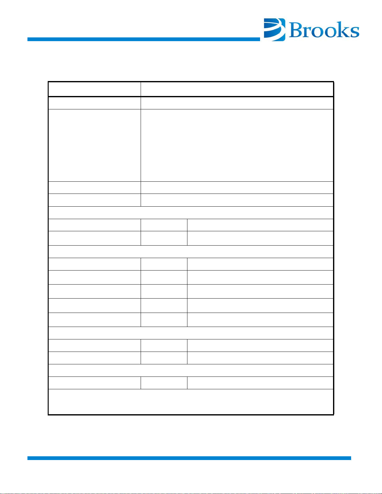
Table 1-13: On-Board 500 ISO-K Cryopump Specifications
Parameter Chevron Array Specifications
Rough Pump Connection NW 25 ISO KF
Integrated Hardware Keypad/Display (optional)
Roughing Valve
Purge Valve
Cryopump TC Gauge
1st Stage Diode
2nd Stage Diode
2nd Stage Heater
2 Setpoint Relays
RS-232 Interface
Weight 118.2 kg/260 lbs.
Dimensions Refer to Installation/Interface Drawing
Vacuum Requirements
Crossover torr-liters 600
Ultimate Pressure
1
torr 7.5E-9
Pumping Speed
Water liters/sec 30000
Nitrogen
Hydrogen
Argon
2,3
2,3
2,3
Argon Throughput
2,3
liters/sec 10000
liters/sec 12000
liters/sec 8400
SCCM 1000
Pumping Capacity
Argon std.liters 6000
Hydrogen std.liters 45 (@5E-6 Torr)
Regen/Cool down Time
Full (Typical) Minutes 225
1. At 38 C ambient radiation
2. At 20 C ambient radiation
3. At 20K Second Stage temperature
1-1-18 © 2013 Brooks Automation Inc Part No. 8040491, Rev. AB, 01/11/2013
Page 37

Theory of Operation
Each On-Board Cryopump consists of a cold head and a vacuum vessel as shown
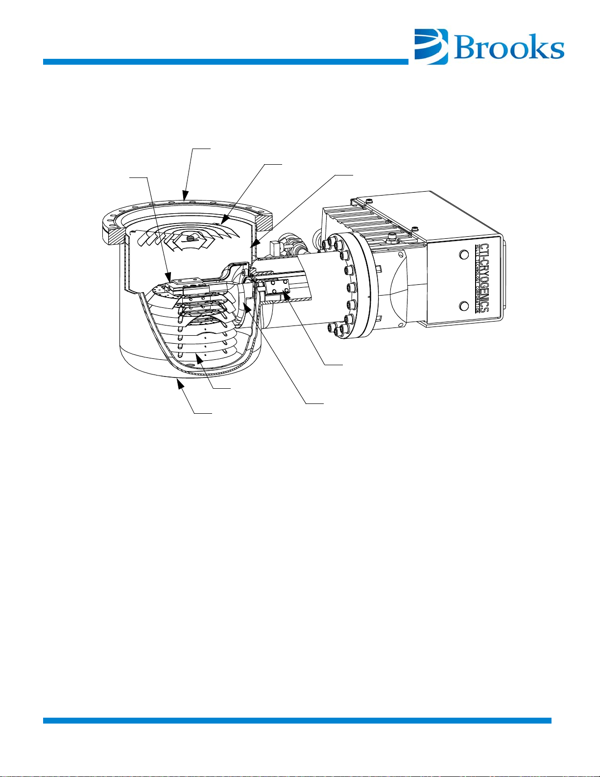
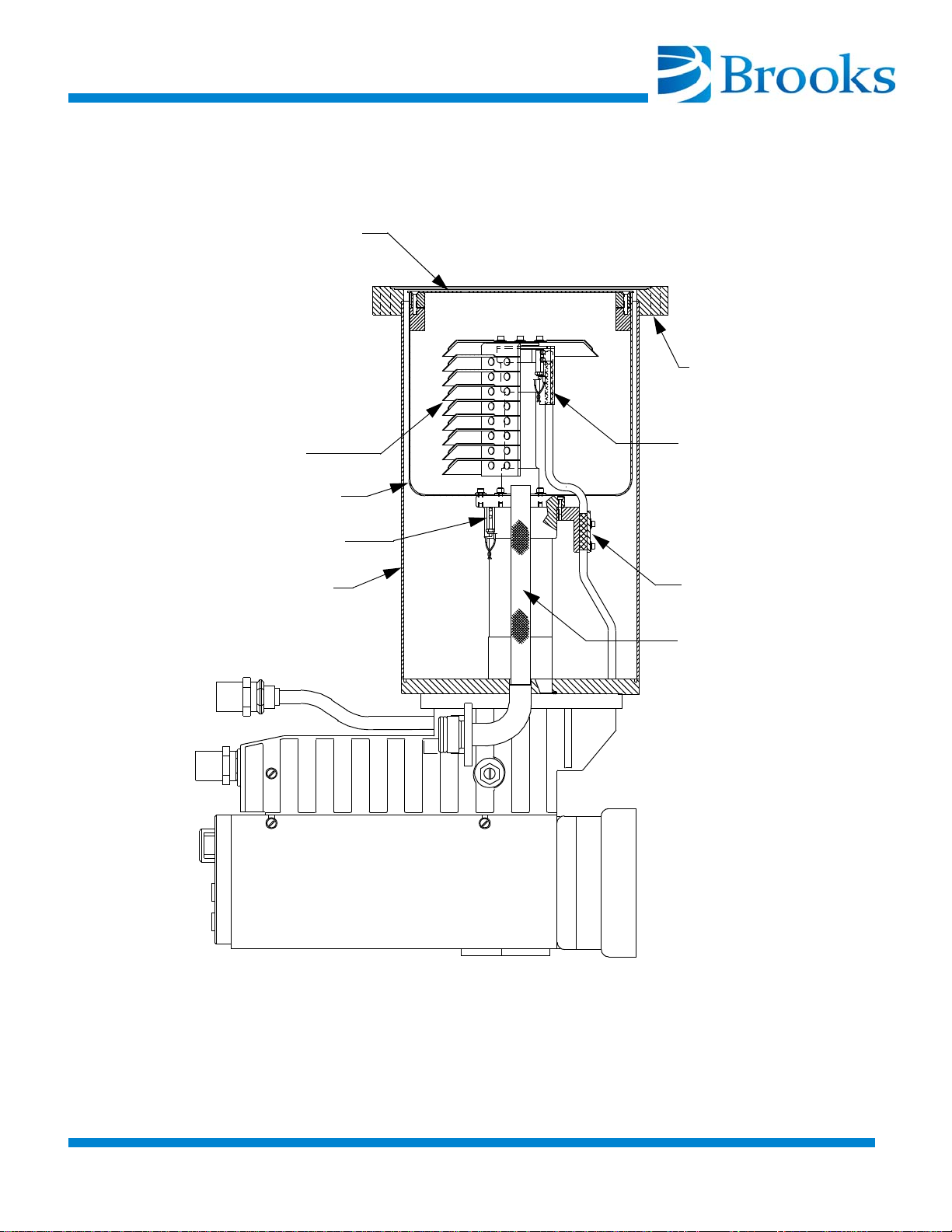
in Figure 1-5 and Figure 1-6. An 80K condensing array, a 15K array, cold head station heaters, and an 80K radiation shield are located in the vacuum vessel. The
cold station heaters and 15K array are secured to the cold head, which is welded
to the vacuum vessel. The cold head provides cooling to the three arrays. Gases
are removed from your vacuum chamber, thereby creating a vacuum when they
are condensed or adsorbed on the cryogenically-cooled arrays.
Cold Head
The cold head consists of a two-stage cold head cylinder, which is part of the vacuum vessel, and the drive unit displacer assembly that together produce closedcycle refrigeration at temperatures ranging from 60 to 120K for the first-stage cold
station and 10 to 20K for the second-stage cold station, depending on operating
conditions. Within the drive unit displacer assembly, the drive unit actuates the
displacer-regenerator assembly located in the cold head cylinder and thereby controls the flow of helium into the cold head. Within the drive unit are located the
crankcase and drive motor, which is a direct-drive constant-speed motor, operating at 72 rpm on 60 Hz power and 60 rpm on 50 Hz power.
During operation, high pressure helium from the compressor enters the cold head
at the helium supply connector, and flows through the displacer-regenerator
assembly, crankcase, and motor housing before exiting through the helium gas
return connector and returning to the compressor. Helium expansion in the displacer-regenerator assembly provides cooling at the first and second stage cold
stations.
Vacuum Vessel and Arrays
The 80K array, as shown in Figure 1-5 and Figure 1-6, condenses water and
hydrocarbon vapors. The 15K array condenses nitrogen, oxygen, and argon while
the specially processed charcoal of this array traps helium, hydrogen, and neon.
The temperature of the cold head stations, to which the 15K array and 80K radiation shield are attached, is measured by temperature sensors and transmitted to
the On-Board controller for display.
Compressor Gas and Oil Flows
Helium returning from the cryopump cold head enters the compressor and a
small quantity of oil is injected into the gas stream, thereby overcoming helium's
low specific heat and inability to carry heat produced during compression.
Helium is then compressed and passed through a heat exchanger for removal of
compression-caused heat.
© 2013 Brooks Automation Inc Part No. 8040491, Rev. AB, 01/11/2013 1-1-19
.
Page 38
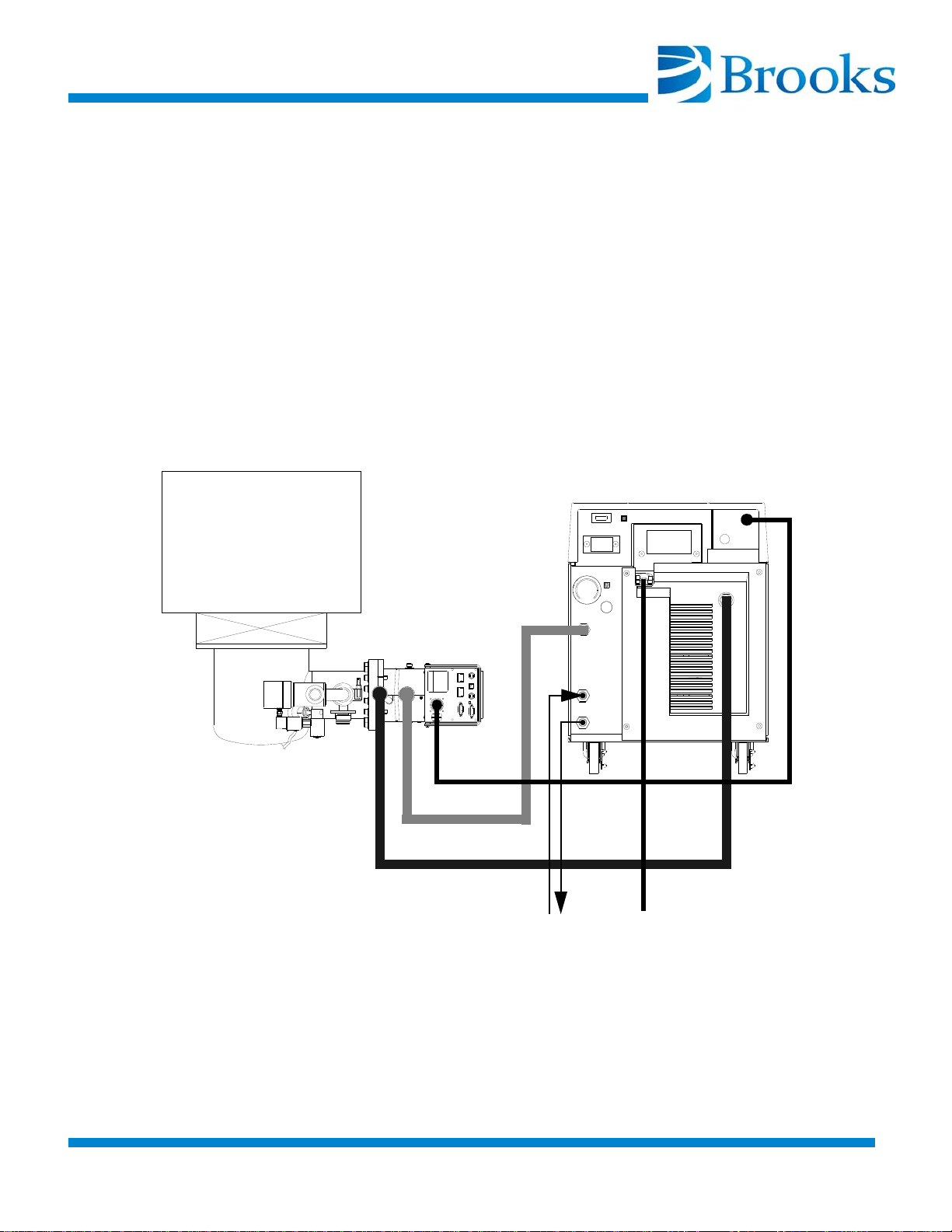
The helium continues its flow through an oil-mist separator and a charcoal filter
9600 COMPRESSOR
ON-BOARD 8F
HIGH-VACUUM
CRYOPUMP
VACUUM
CHAMBER
ON-BOARD POWER
HELIUM SUPPLY
HELIUM RETURN
POWER
WATER
adsorber (cartridge), within the compressor, where oil and contaminants are
removed. A differential pressure relief valve in the compressor limits the operating pressure differential between the helium supply and return lines, thereby
allowing compressor operation without cold head operation. When cold head
operation reaches a steady-state condition, further pressure regulation is unnecessary.
A typical On-Board Cryopump system is shown in Figure 1-4.
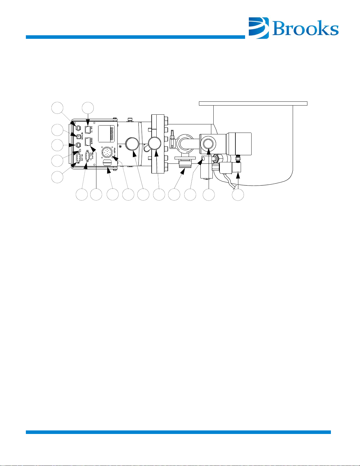
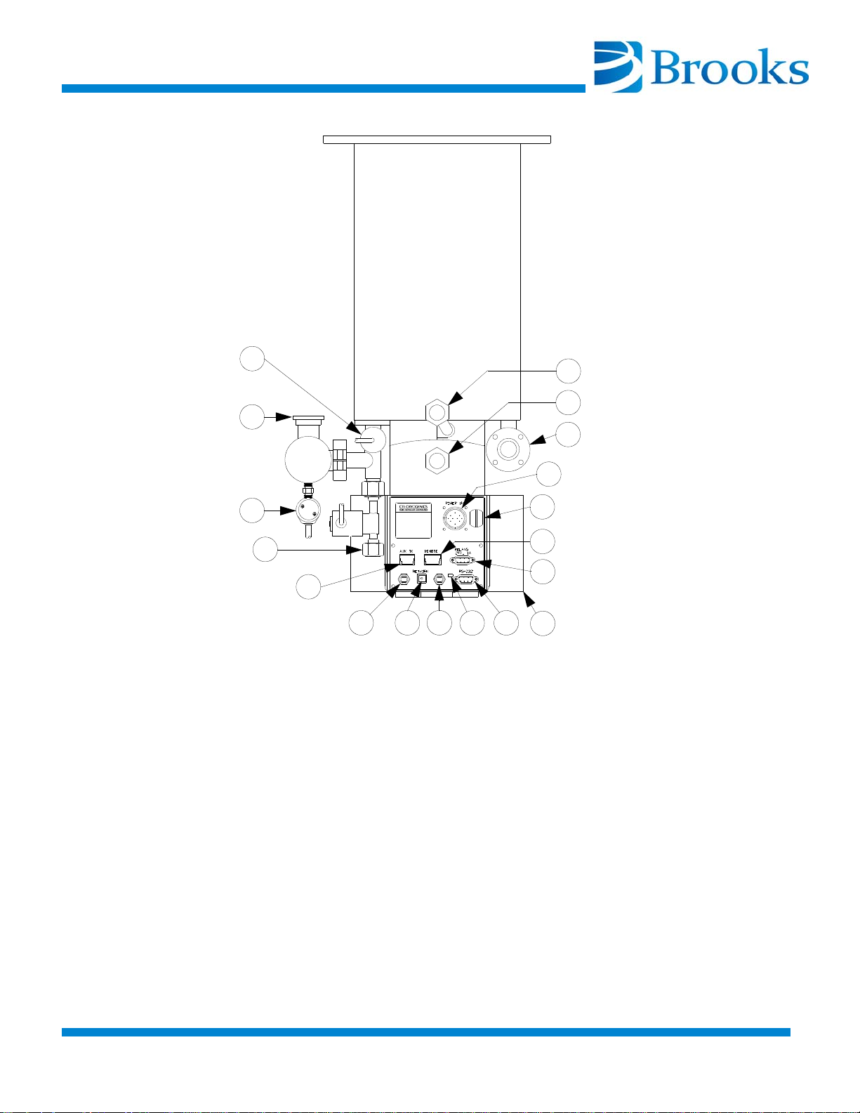
The location of helium and electrical components of typical flat and straight OnBoard Cryopumps are shown in Figure 1-7 and Figure 1-8 respectively.
Figure 1-4: Typical On-Board Cryopump System
1-1-20 © 2013 Brooks Automation Inc Part No. 8040491, Rev. AB, 01/11/2013
Page 39
80K Array
Mounting
Radiation Shield
Second Stage
15K Array
Vacuum Vessel
First Stage
Heater
Heater
Flange
Cup Shield
© 2013 Brooks Automation Inc Part No. 8040491, Rev. AB, 01/11/2013 1-1-21
.
Figure 1-5: Cutaway View of a Typical Flat On-Board Cryopump Vessel
Page 40
80K Array
Mounting
Radiation Shield
Second Stage
15K Array
Vacuum Vessel
First Stage
Heater
Heater
Flange
Standpipe
Filter
First Stage Diode
Figure 1-6: Cutaway View of a Typical Straight On-Board Cryopump Vessel
1-1-22 © 2013 Brooks Automation Inc Part No. 8040491, Rev. AB, 01/11/2013
Page 41
1
2
3
2
4
5
6
7
8
9
10
11
12
13
LEGEND
1. Auxiliary Thermocouple Gauge Connector
2. Network Connectors
3. Network Pump Identification Switch
4. Power Indicator Lamp
5. RS-232 Computer Interface Connector
6. Setpoint Relay Connector
7. Remote Keypad Connector
8. Safety Interlock Screw
9. Input Power Connector
10. Helium Return Connector
11. Helium Supply Connector
12. Pressure Relief Valve
13. Purge Gas Connection (10 - 25 psig or 40 - 80 psig) 1/8 NPT
14. Rough Pump Connection
15. Air Supply Connection (60 - 80 psi, 1/8 NPT)
15
14
ON-BOARD
®
FastRegen™ Control
Sputtering
Figure 1-7: Typical Flat On-Board Cryopump Component Identification
© 2013 Brooks Automation Inc Part No. 8040491, Rev. AB, 01/11/2013 1-1-23
.
Page 42
ON-BOARD
®
FastRegen™ Control
Sputtering
2
3
4
5
6 7 6
8
9
12
13
15
16
17
14
LEGEND
1. Thermocouple Gauge
2. Rough Pump Connection
3. Air Supply Connection (60 - 80 psig 1/8 NPT)
4. Purge Gas Connection (10 - 25 psig or 40 - 80 psig 1/8 NPT)
5. Auxiliary Thermocouple Gauge Connector
6. Network Connectors
7. Network Pump Identification Switch
8. Power Indicator Lamp
9. RS-232 Computer Interface Connector
10. Keypad/Display
1 1. Setpoint Relay Connector
12. Remote Keypad Connector
13. Safety Interlock Screw
14. Input Power Connector
15. Pressure Relief Valve
16. Helium Return Connector
17. Helium Supply Connector
1
11
10
Figure 1-8: Typical Straight On-Board Cryopump Component Identification
1-1-24 © 2013 Brooks Automation Inc Part No. 8040491, Rev. AB, 01/11/2013
Page 43
Introduction
Keypad/Display
Installation
(Refer to Page 2-2)
On-Board Cryopump Installation
(Refer to Page 2-6)
Roughing Pump
Connection
(Refer to Page 2-10)
Purge Gas Connection
(Refer to Page 2-10)
AUX TC Gauge
Installation
(Refer to Page 2-11)
Setpoint Relays
(Refer to Page 2-11)
Remote
Keypad/Display Installation
(optional)
(Refer to Page 2-12)
Vent Pipe Connection
(Refer to Page 2-9)
Helium Line
Connections
(Refer to Page 2-10)
Rough Valve Gas
Connection
(Refer to Page 2-10)
Section 2 - Installation
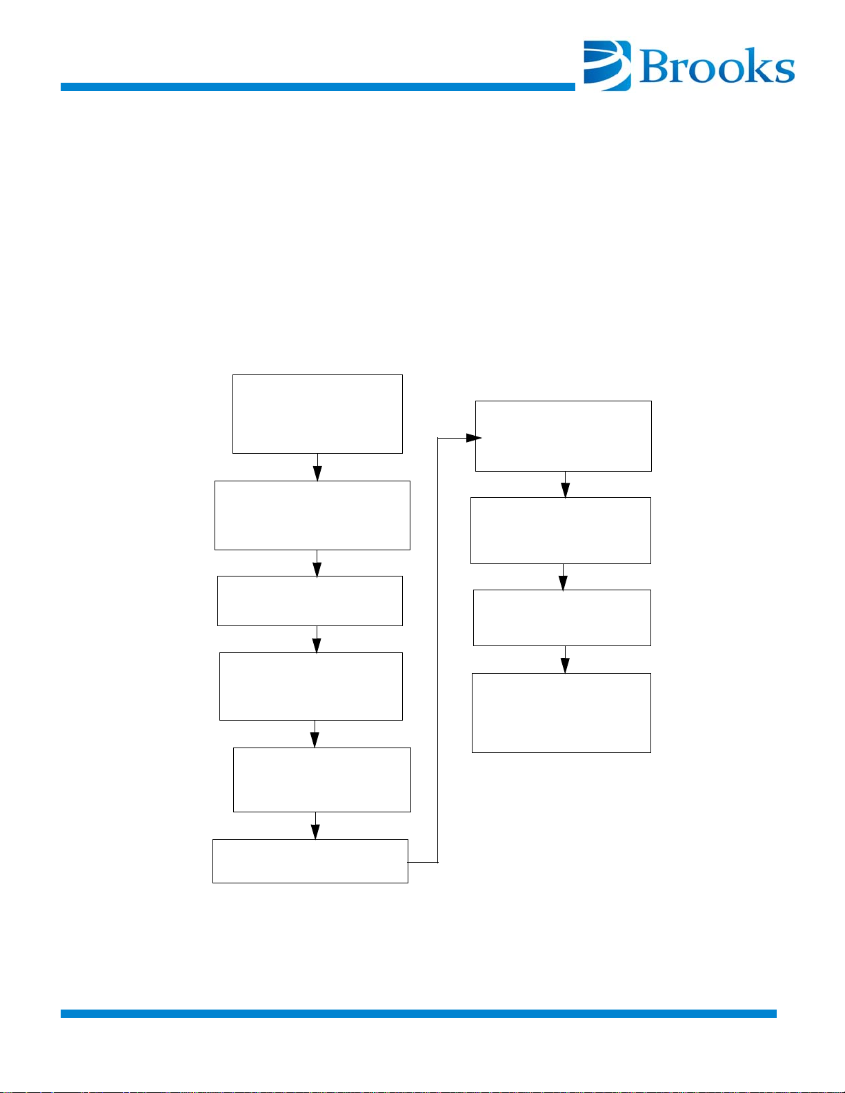
Installation information is presented for experienced and inexperienced OnBoard Cryopump system technicians. The flowchart in Figure 2-1 highlights the
major tasks of On-Board Cryopump installation. Refer to Figure 2-1 and the
appropriate installation procedure within this section for the type of On-Board
Cryopump being installed.
Figure 2-1: Block Diagram for On-Board Cryopump Installation
©2013 Brooks Automation Inc Part No. 8040491, Rev. AB, 01/11/2013 2-2-1
.
Page 44
Keypad/Display Installation
Back Plate
Mounting Screws
(Keypad
Removed)
Keypad/Display
Handle
Backplate
Keypad/Display
Mounting Screws
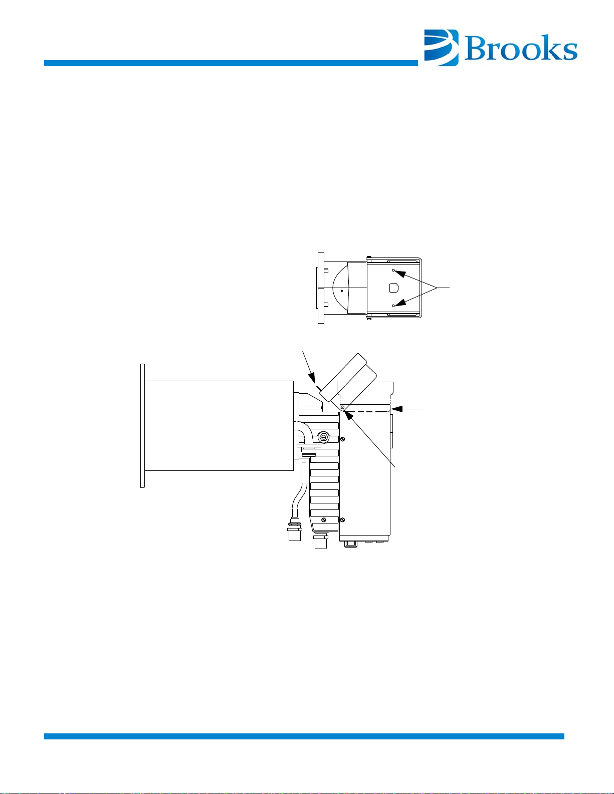
The keypad/display can be installed on the On-Board Cryopump in four different
positions, identified as positions A, B, C, and D.
Typically, the On-Board Cryopump is shipped with the keypad/display mounted
in position A, as shown in Figure 2-2. This is the orientation most likely to be used
for the majority of installations. Installing the keypad/display in position B, C, or
D is easy.
Position A
2-2-2 ©2013 Brooks Automation Inc Part No. 8040491, Rev. AB, 01/11/2013
Figure 2-2: Keypad/Display Mounting Position A
Page 45
Position B
Back Plate
Mounting Screws
(Keypad
Removed)
Keypad/Display
Handle
Backplate
Keypad/Display
Mounting Screws
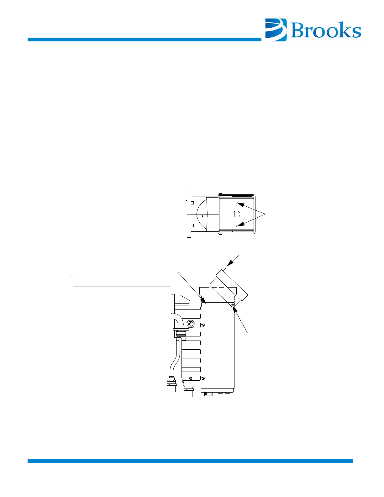
Refer to Figure 2-3 and the following procedure to install the keypad/display in
position B.
1. Remove the 2 screws, washers, and nuts holding the keypad/
display to the back plate.
2. Remove the 2 screws and washers holding the back plate.
3. Rotate the back plate, being careful not to strain the cable, so the
keypad/display mounting screw holes are oriented as shown in
Figure 2-3.
4. Mount the back plate using the 2 screws and washers removed
during step 2.
5. Remount the keypad/display using the 2 screws, washers, and
nuts removed in step 1 as shown in
Figure 2-3.
Figure 2-3: Keypad/Display Mounting Position B
©2013 Brooks Automation Inc Part No. 8040491, Rev. AB, 01/11/2013 2-2-3
.
Page 46
Position C
Back Plate
Mounting Screws
(Keypad
Removed)
Keypad/Display
Handle
Backplate
Keypad/Display
Mounting Screws
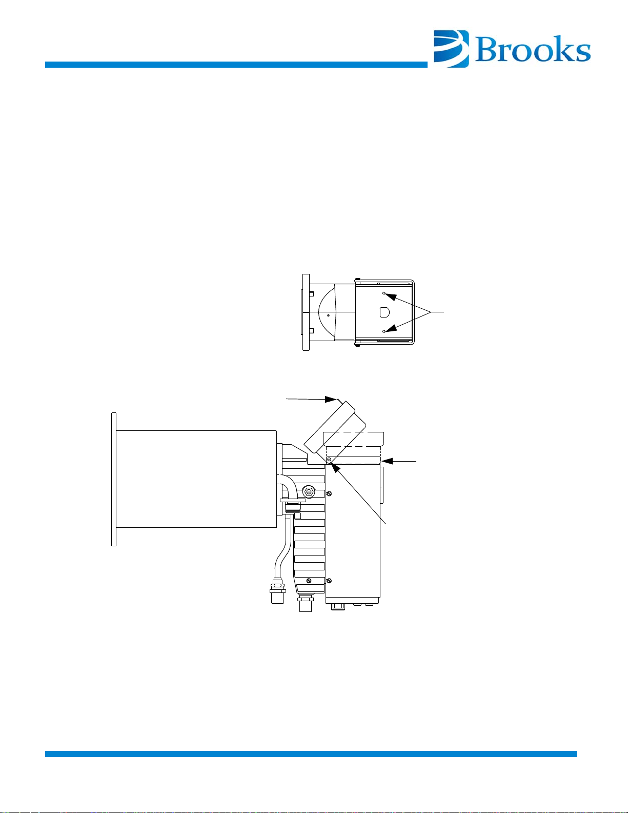
Refer to Figure 2-4 and the following procedure to install the keypad/display in
position C.
1. Remove the 2 screws, washers, and nuts holding the keypad/
display to the back plate.
2. Turn the keypad/display over.
3. Remount the keypad/display as shown in Figure 2-4 using the 2
screws, washers, and nuts removed in step 1.
Figure 2-4: Keypad/Display Mounting Position C
2-2-4 ©2013 Brooks Automation Inc Part No. 8040491, Rev. AB, 01/11/2013
Page 47
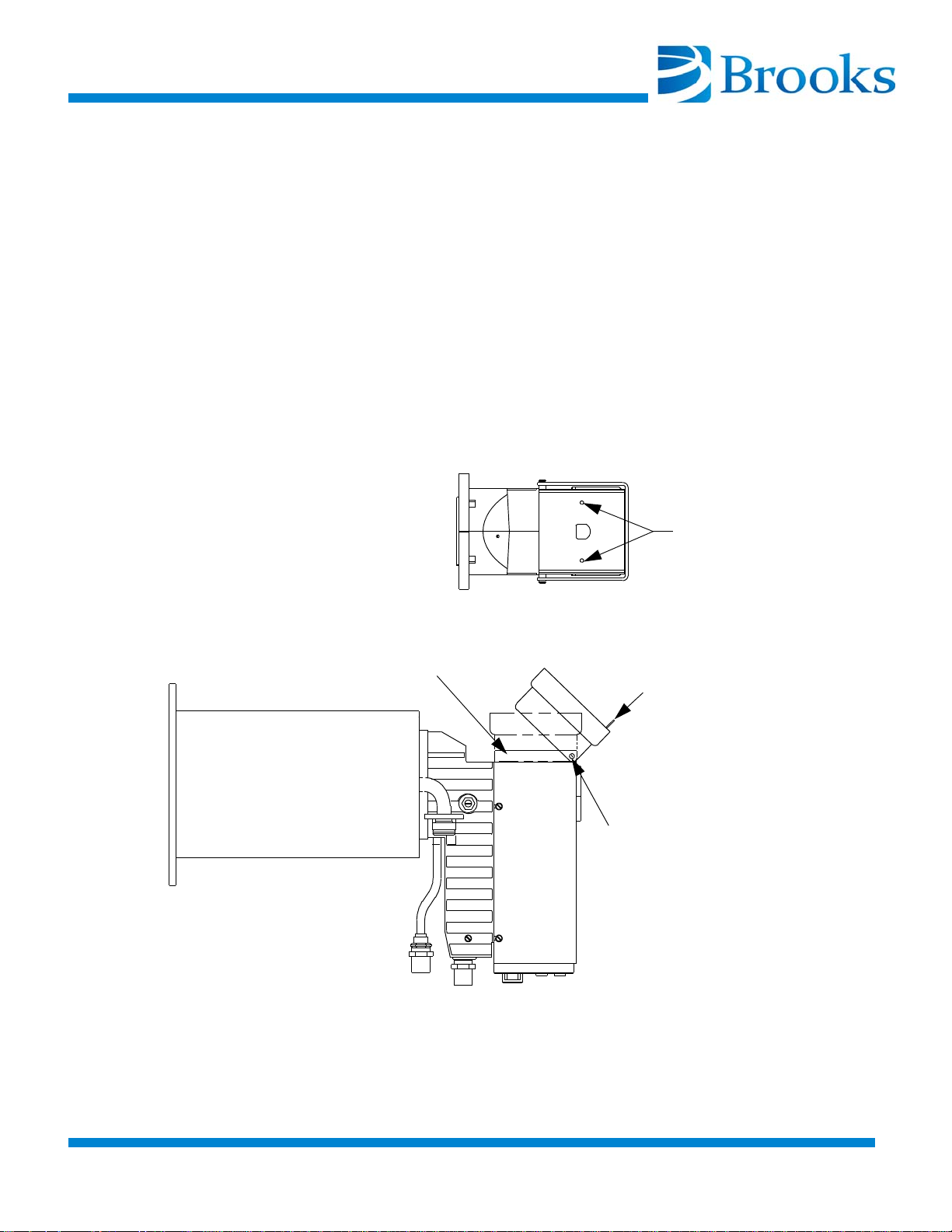
Position D
Back Plate
Mounting Screws
(Keypad
Removed)
Keypad/Display
Handle
Backplate
Keypad/Display
Mounting Screws
Refer to Figure 2-5 and the following procedure to install the keypad/display in
position D.
1. Remove the 2 screws, washers, and nuts holding the keypad/
display to the back plate.
2. Remove the 2 screws and washers holding the back plate.
3. Rotate the back plate, being careful not to strain the cable, so the
keypad/display mounting screw holes are oriented as shown in
Figure 2-5.
4. Remount the back plate using the 2 screws and washers removed
during step 2.
5. Remount the keypad/display using the 2 screws, washers, and
nuts removed in step 1 as shown in
Figure 2-5.
Figure 2-5: Keypad/Display Mounting Position D
©2013 Brooks Automation Inc Part No. 8040491, Rev. AB, 01/11/2013 2-2-5
.
Page 48
On-Board Cryopump Installation
The following procedure does not apply to the On-Board 500 Cryopump. Refer to
the On-Board 500 Cryopump Installation procedure to install these pumps.
The On-Board Cryopump may be installed in any orientation without affecting its
performance.
Before mounting the On-Board Cryopump to the vacuum system, ensure that a
high-vacuum isolation valve (Hi-Vac valve) is installed between the On-Board
Cryopump and the vacuum chamber.
This valve isolates the On-Board Cryopump from the chamber during rough
pumping, cooldown, and regeneration.
Install the On-Board Cryopump on the vacuum system as follows:
1. Remove the protective cover from the main flange of the OnBoard Cryopump.
2. Clean all sealing surfaces and install the O-ring or metal seal gasket as appropriate.
Check with the OEM for proper cleaning materials.
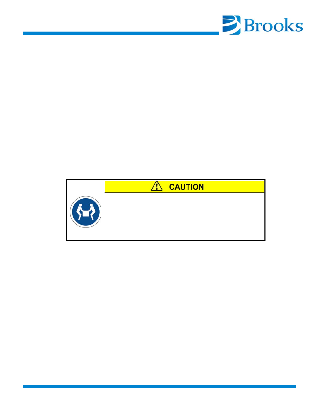
Two-Person Lift Required
Certain model pumps weigh in excess of 24 kg/52 lbs.
Lifting heavy loads can result in serious injury.
Use a 2-person lift or a lifting aid when attempting to lift
these pumps.
3. Mount the On-Board Cryopump to the Hi-Vac valve or vacuum
chamber mounting flange. Be sure all mounting bolts are secure.
2-2-6 ©2013 Brooks Automation Inc Part No. 8040491, Rev. AB, 01/11/2013
Page 49
On-Board 500 Cryopump Installation
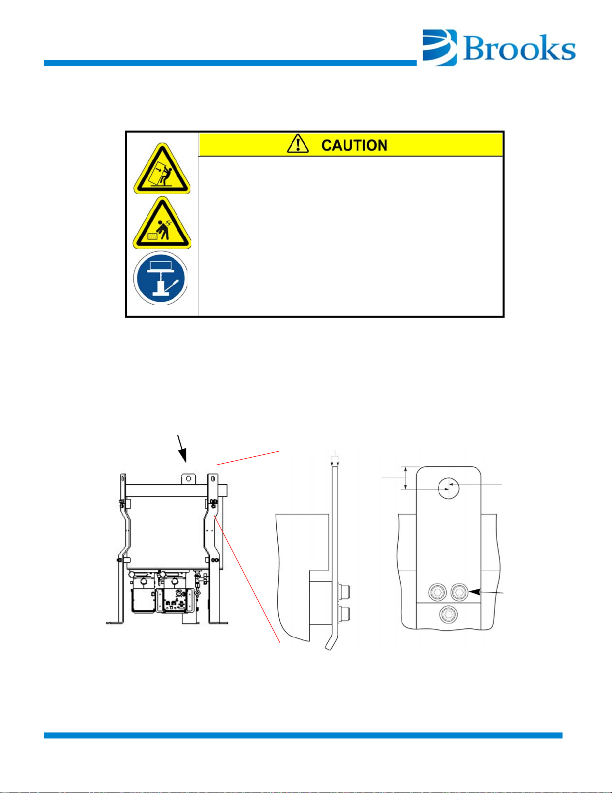
Lifting bar detail
1/4-inch thickness
1-inch clearance
1-inch
diameter
SHCS
hole
Figure 2-6: Lifting Bars
x 2
Also refer to the On-Board 500 Cryopump Quick Installation Guide (174166).
Tip Over/Heavy Object Hazard
The On-Board 500 Cryopump weighs 118.2 kg/260 lbs.
Lifting the On-Board 500 Cryopump by fewer than all 3
lift points can result in instability of the pump, leading to
personnel injury.
Always use a lifting aid when attempting to lift or move
this pump.
1. When lifting the On-Board 500 Cryopump from the packaging
container, always attach cables to each of the 3 lifting bars pro
vided for the purpose.
Note: Each lifting bar is 1/4-inch thick with a 1-inch diameter hole and 1-inch
clearance. Refer to
Figure 2-6.
-
©2013 Brooks Automation Inc Part No. 8040491, Rev. AB, 01/11/2013 2-2-7
.
Page 50

2. Transport the pump to the tool where it will be installed.
3. Before installing the cryopump on the tool, first remove the lifting
bars from the support legs. Use a 3/8-inch Allen wrench to remove
the 2 SHCSs, with washer and lock washer, that secure each of the
3 lifting bars. Refer to
Figure 2-6.
NOTICE
Cryopumps can be damaged by the use of a hoisting strap.
When a hoisting strap is used, remove interference between the
strap and the keypad and cables.
4. When installing the pump in a horizontal orientation, leave the
support legs attached, cradle the vessel at the Center of Gravity,
attach a separate cable to one support leg to maintain horizontal
orientation, and use an overhead lifting device.
5. When installing the pump in a vertical orientation, use the support
legs.
6. Remove the protective cover from the main flange of the On-Board
Cryopump.
7. Clean all sealing surfaces and install the O-ring or metal seal gasket as appropriate.
Check with the OEM for proper cleaning materials.
8. Mount the On-Board Cryopump to the Hi-Vac valve or vacuum
chamber mounting flange. Be sure all mounting bolts are secure.
2-2-8 ©2013 Brooks Automation Inc Part No. 8040491, Rev. AB, 01/11/2013
Page 51
Vent Pipe Connection
The On-Board Cryopump pressure relief valve can be vented directly into the
room or can be connected to an exhaust system.
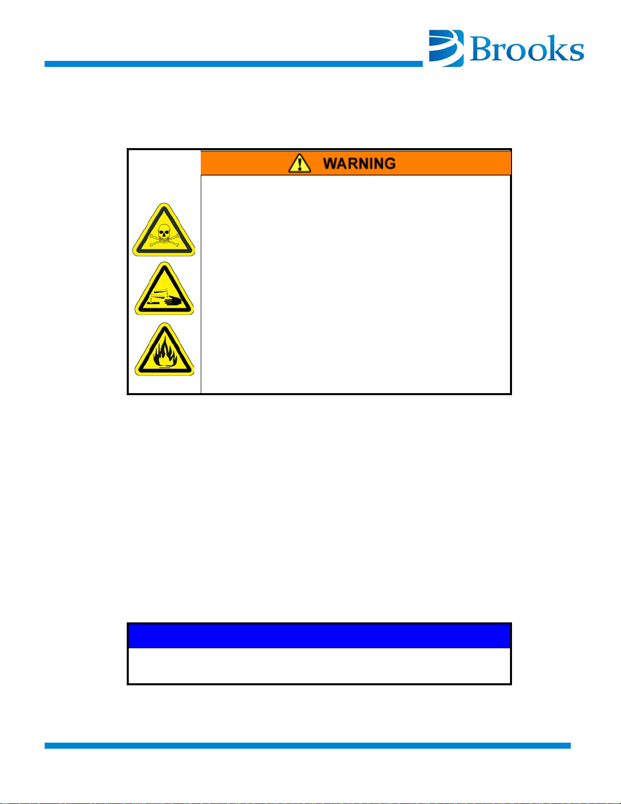
Toxic, flammable, and/or corrosive process gases or
liquids pumped or captured by an On-Board, On-Board
IS, or Cryo-Torr product could cause severe injury on
contact.
Always vent toxic, flammable, and/or corrosive gases
or liquids to a safe location using an inert purge gas.
The customer is responsible for safely exhausting
these gases.
Clearly identify on the cryopump which toxic/corrosive
gas or liquid is contained in the pump before storing or
shipping it to Brooks Automation.
Toxic, Flammable, Corrosive Gases
When toxic, corrosive, or flammable gases are pumped, a vent pipe must be connected to the On-Board Cryopump relief valve and directed to a safe location.
When connecting a vent pipe to your On-Board Cryopump, the 1.30-inch diameter x 1.38-inch length volume of clearance around the relief valve must remain
open for proper relief valve operation.
A Relief Valve Adapter Exhaust Kit (BROOKS- CRYOGENICS P/N
8080250K008) is available. Call you local customer support center for more infor
mation.
Note: The On-Board 500 Cryopump ships with an exhaust cap that provides the specified
volume. The cap requires a 1/2-inch FMPT connection.
The enhanced On-Board 8F Cryopump installation kit includes a 6 foot (1.83 m)
length of 1/2 inch ID (12.7 mm) polytube with associated fittings to allow venting
of the cold exhaust as desired in cases where a hard plumbed manifold is not
used.
NOTICE
For the enhanced On-Board 8F Cryopump, if an exhaust manifold
is used, it must have a minimum ID of a 1/2 inch (12.7 mm).
-
©2013 Brooks Automation Inc Part No. 8040491, Rev. AB, 01/11/2013 2-2-9
.
Page 52

Roughing Pump Connection
The roughing system must provide 10 cfm (measured at atmosphere and at each
On-Board Cryopump) to successfully utilize On-Board FastRegen capability.
Connect your On-Board Cryopump to a roughing pump system using a roughing
line with the largest inside diameter possible to minimize the roughing time
required during start-up procedures prior to normal operation. The roughing
pump should have a blank-off pressure of less than 20 microns.
The roughing pump connects to the On-Board Cryopump roughing valve as
shown in Figure 1-7 at Rough Pump Connection #14 or Figure 1-8 at Rough Pump
Connection #2. The valve will accept an ISO NW-25 flange.
1. Install the roughing pump line to the On-Board Cryopump
roughing valve port using the clamp provided.
2. Ensure the clamp is tightened securely.
Rough Valve Gas Connection
Attach the gas supply line from a 60-80 psig gas supply to the 1/8 NPTF roughing
valve fitting. Make sure to attach the gas supply line to the valve fitting that has a
filter screen at the attachment connection.
Purge Gas Connection
Connect your purge gas supply line to the purge valve 1/8 NPTF fitting. Adjust
the supply pressure to 10 - 25 psig or 40 - 80 psig, depending upon the label on the
purge valve, yielding 1-2 cfm.
Helium Line Connections
Make the connections between the On-Board Cryopump and compressor. Refer
to Figure 1-7 or Figure 1-8 while making the component interconnections.
1. Remove all dust plugs and caps from the supply and return
lines, compressor, and On-Board Cryopump. Check all fittings.
2. Connect the helium-return line from the gas-return connector on
the rear of the compressor to the gas-return connector on the OnBoard Cryopump.
3. Connect the helium supply line from the supply connector on the
cartridge to the gas-supply connector on the On-Board Cryopump.
4. Attach the supply and return line identification decals
(BROOKS-CRYOGENICS supplied) to their respective connectors.
Verify proper helium supply static pressure as described in the Installation Section of the appropriate Compressor Manual.
2-2-10 ©2013 Brooks Automation Inc Part No. 8040491, Rev. AB, 01/11/2013
Page 53

Auxiliary (AUX) TC Gauge Installation
An auxiliary TC gauge tube, P/N 8112096, and an auxiliary TC gauge cable
assembly, P/N 8112098G001, are available for purchase.
The auxiliary TC gauge reads vacuum between 1 and 1000 microns. The gauge
comes with a 1/8 NPT pipe thread.
Setpoint Relays
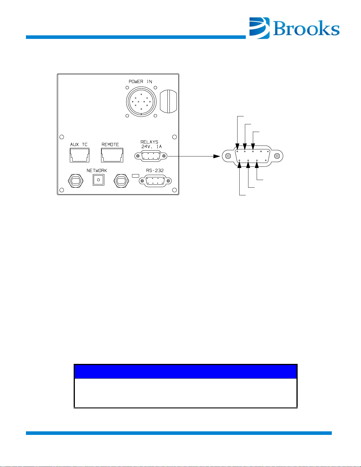
The setpoint relays are two mechanical relays that are incorporated into the OnBoard Cryopump for the User's application. The relays are rated at 1 amp at 25V
AC/DC. The relays have both normally-open and normally-closed contacts. Connection to the relays is made through the 9-pin D connector labeled (Relays) on
the connector plate on the On-Board Cryopump. Refer to Figure 2-7 for pin identification.
Refer to On-Board Cryopump Module Programming and Operation Instructions
(8040410) for instructions on programming the setpoint relays.
When the setpoint relays are used, connection to the relays (R1 and R2) is made
via the setpoint relay connector located at the rear of the On-Board controller. If
your On-Board Cryopump configuration requires use of the setpoint relays, refer
to Figure 2-7 and proceed as follows:
1. Screw the TC tube into a 1/8 NPT fitting.
2. Attach the auxiliary TC cable to the tube and to the connector on
the On-Board module. Refer to
Note: It may be necessary to zero the auxiliary TC gauge. Refer to the On-Board
Cryopump Module Programming and Operation Instructions (8040410) for
more information.
1. Determine whether your On-Board equipment requires setpoint relay contacts to be either in a normally-open or normally-closed position for your application.
Figure 2-7.
2. Referring to Figure 2-7, prepare a 9-pin DSub mating connector,
meeting MIL DTL 24308/1-1 and equipment requirements.
3. Connect the setpoint relay receptacle to its connector located on
the On-Board controller.
4. Program the relays as described in the appropriate On-Board
Cryopump Module Programming and Operation Instructions
(8040410).
©2013 Brooks Automation Inc Part No. 8040491, Rev. AB, 01/11/2013 2-2-11
.
Page 54
Remote Keypad/Display Installation (Optional)
Normally Open (NO)
Normally Closed (NC)
Common
Common
Normally Closed (NC)
Normally Open (NO)
12 345
6
7
89
RELAY 2
RELAY 1
Figure 2-7: Setpoint Relays Connection and Pin Identification
The On-Board Cryopump can be operated both from a remote and from an
attached keypad/display.
The remote keypad/display is a 19-inch rack-mountable unit.
1. Mount the unit to a rack.
2. Connect the unit to the REMOTE connector on the On-Board
Cryopump Module using the cable supplied with the remote key
pad.
NOTICE
When installing remote keypad cable, care should be taken to
route the cable away from power cables and any equipment that
may generate excessive EMI conditions
2-2-12 ©2013 Brooks Automation Inc Part No. 8040491, Rev. AB, 01/11/2013
-
Page 55

Introduction
The primary indication of trouble in a vacuum pumping system is a rise in base
pressure of your vacuum chamber. A rise in the base pressure may be caused by a
leak in the vacuum system, a fault in the On-Board Cryopump, or by saturation of
the 15K cryo-adsorbing charcoal array within the
On-Board Cryopump (regeneration may be necessary). If the On-Board
Cryopump temperature is below 20K it should pump at rated capacity; a high
base pressure is usually caused by an air-to-vacuum leak in the system.
If you suspect a leak in your vacuum system, isolate the On-Board Cryopump by
closing the Hi-Vac valve and leak check your vacuum chamber. If no leaks are
found, a leak may be present below the Hi-Vac valve (cryopump). Leak checking
below the Hi-Vac valve should be performed with the On-Board Cryopump shut
off and at room temperature. Leak checking while the On-Board Cryopump is
operating may mask leaks that are present (due to the ability of the cryopump to
pump helium). If no leak is found, refer to the cryopump troubleshooting procedures summarized in Table 3-1.
Section 3 - Troubleshooting
The problems presented in Table 3-1 are followed by possible causes and corrective actions. The causes and corresponding actions are listed in their order of
probability of occurrence.
Maintaining a log of certain parameters during normal operation is a valuable
tool for troubleshooting the cryopump. The log may contain many parameters;
however, the following minimum parameters should be included: the cooldown
time to 20K, the roughing time to 50μ, the time to base pressure at crossover, the
time between regeneration cycles, and the compressor pressure reading.
©2013 Brooks Automation Inc Part No. 8040491, Rev. AB, 01/11/2013 3-3-1
.
Page 56

Technical Inquiries
Please refer to Contacting Brooks’ Technical Support in the front of this manual.
Table 3-1: Cryopump Troubleshooting Procedures
Problem Possible Cause Corrective Action
High base pressure of vacuum system, and a cryopump temperature
below 20K.
High base pressure of vacuum system, and a cryopump temperature
above 20K.
Air-to-vacuum leak in vacuum system or in cryopump.
High partial pressure of noncondensables (helium, hydrogen, or
neon) within the cryopump
because the 15K array has reached
full capacity.
One of the arrays is loose, thereby
preventing good thermal contact
with its cold station on the cold
head.
Decrease in cryopump cold head
performance.
High partial pressure of non-condensables (helium, hydrogen, or
neon) within the cryopump
because the 15K array has reached
full capacity.
Check cryopump relief valve for
proper seating.
Check cryopump for leaks.
Check vacuum chamber and HiVac valve for leaks.
Regenerate the cryopump as
described in the appropriate On-
Board Cryopump Module Programming and Operation Instructions
(8040410).
Warm the cryopump to ambient
temperature, and retighten the
arrays to 15-20 inch/pounds.
If the helium return pressure gauge
reads below the normal operating
return pressure 100-120 psig (690827 kPa), add gas as described in
the appropriate compressor manual.
Regenerate the cryopump as
described in the appropriate On-
Board Cryopump Module Programming and Operation Instructions
(8040410).
Excessive thermal load on frontal
array.
Reduce the thermal radiation load
by 1) shielding the cryopump or 2)
lowering the temperature of the
radiating surface.
3-3-2 ©2013 Brooks Automation Inc Part No. 8040491, Rev. AB, 01/11/2013
Page 57

Table 3-1: Troubleshooting Procedures (continued)
Problem Possible Cause Corrective Action
Cryopump fails to cool down to the
required operating temperature or
takes too long to reach that temperature (20K).
No display. No power to On-Board cryopump. Check electrical connections; be
Display does not update, and/or
keys do not function.
Low helium supply pressure. Add gas as described in the appro-
priate compressor manual.
Compressor problems. Refer to the appropriate compres-
sor manual.
Leak in vacuum system or
cryopump.
Incomplete regeneration may not
have fully cleaned the adsorbing
array. Partial pressures of non-condensables (hydrogen, neon or
helium) may remain.
Electronics has locked up. Try to reboot the system by turning
Check the cryopump relief valve for
proper seating.
Check cryopump for leaks.
Check vacuum system for leaks.
Regenerate the cryopump as
described in the appropriate On-
Board Cryopump Module Programming and Operation Instructions
(8040410).
sure the power switch at the compressor controller is turned on.
Check fuses. If power is turned on,
try turning it off and on to reboot
the electronics. Change electronics
module.
the On-Board power switch located
at the compressor controller off and
on. Replace the On-Board electronic
module.
Rough valve clicks but does not
open and close.
Too little or no air pressure to drive
valve.
Increase air pressure to 60 psig minimum, 80 psig maximum.
©2013 Brooks Automation Inc Part No. 8040491, Rev. AB, 01/11/2013 3-3-3
.
Page 58

This Page Intentionally Left Blank
3-3-4 ©2013 Brooks Automation Inc Part No. 8040491, Rev. AB, 01/11/2013
Page 59

Section 4 - Maintenance
Helium Circuit Decontamination
The information in Section 4 - Maintenance will guide you through the process of
removing gaseous contamination from an On-Board Cryopump helium circuit by
freezing the contaminant in the coldhead of the On-Board Cryopump. A contaminated helium circuit will cause the On-Board Cryopump to operate in a noisy
manner, typically referred to as ratcheting, which degrades On-Board Cryopump
performance.
Separate decontamination of the compressor is only required if the
compressor has been opened to atmosphere or the helium pressure
in the compressor has dropped to zero.
Three methods of decontamination are described in Table 4-1 and on the following pages. These methods all have isolating gaseous contamination in common
by freezing them in one or more cold On-Board Cryopumps. The method to be
used will most likely be determined by the amount of time available for the
decontamination.
Method
1. Cooldown and
Sequential decontamination of all
On-Board
Cryopumps
2. Decontamination of
only cold
On-Board
Cryopumps
3. Simultaneous decontamination of all OnBoard
Cryopumps using helium
manifold
Table 4-1: Methods of Decontamination
Starting
Condition
Requires all OnBoard
Cryopumps to
be cold.
Only one
On-Board
Cryopump
needs to be cold.
Only one
On-Board
Cryopump
needs to be cold.
After all On-Board Cryopumps are
cold, 45 minutes to decontaminate the
first On-Board Cryopump. 30 minutes
for each additional On-Board
Cryopump.
45 minutes to decontaminate the first
cold On-Board Cryopump. 30 minutes
for each additional cold On-Board
Cryopump.
45 minutes Acceptable
Estimated Time
If the On-Board Cryopump does not reach its normal operating temperature
(below 20K), then that performance degradation may be caused by any of the fol
lowing:
Effectiveness of
Decontamination
Maximum
Acceptable
(may need to be
repeated in several
months).
-
a. Helium gas contamination
b. Poor vacuum
©2013 Brooks Automation Inc Part No. 8040491, Rev. AB, 01/11/2013 4-4-1
.
Page 60

Performing a Fast or Full regeneration cycle will not remove
gaseous contamination from an On-Board helium circuit. Unless
the decontamination procedure is performed, the noisy On-Board Cryopump
condition will repeat itself within one - four weeks.
Background
The On-Board Cryopump contains a cryogenic refrigerator assembly called a
coldhead. There is no way to visually inspect the internal components, so it is best
to detect problems by listening for unusual sounds. If the coldhead runs quietly
at start up, but begins to make a ratcheting noise after the On-Board Cryopump is
cooled down, then contaminated helium is the most probable cause.
All gases other than helium can freeze in the coldhead. During manufacturing of
On-Board Cryopump systems, gaseous impurities are removed using stringent
manufacturing control. The delivered system contains sufficiently low concentrations of gaseous impurities so they are not of concern.
It is possible, over long periods of operation, that additional gaseous contaminants can be released. These gases, along with any air that is added
accidentally during installation, will collect in the coldhead as frozen gas. The
frozen gas may partially block the regenerator. This increases the amount of
torque required to drive the displacer mechanism to the point that the motor
noise, that is, the ratcheting, may increase and result in coldhead motor stalling.
c. Thermal load on the On-Board Cryopump arrays
These gaseous contaminants can be removed by first freezing them in the coldhead, then disconnecting the helium supply and return lines, warming the coldhead followed by de-pressurizing and pressurizing the helium gas in the
coldhead to remove them. The use of this decontamination procedure will return
most On-Board Cryopumps to proper operation without the need for removal of
the On-Board Cryopump from the tool.
It is strongly recommended that this procedure be performed as soon as possible
after the ratcheting noise appears to minimize mechanical loading on the OnBoard Cryopump drive mechanism.
If any additional help is needed, refer to Contacting Brooks’ Technical Support
in the front of this manual.
4-4-2 ©2013 Brooks Automation Inc Part No. 8040491, Rev. AB, 01/11/2013
Page 61
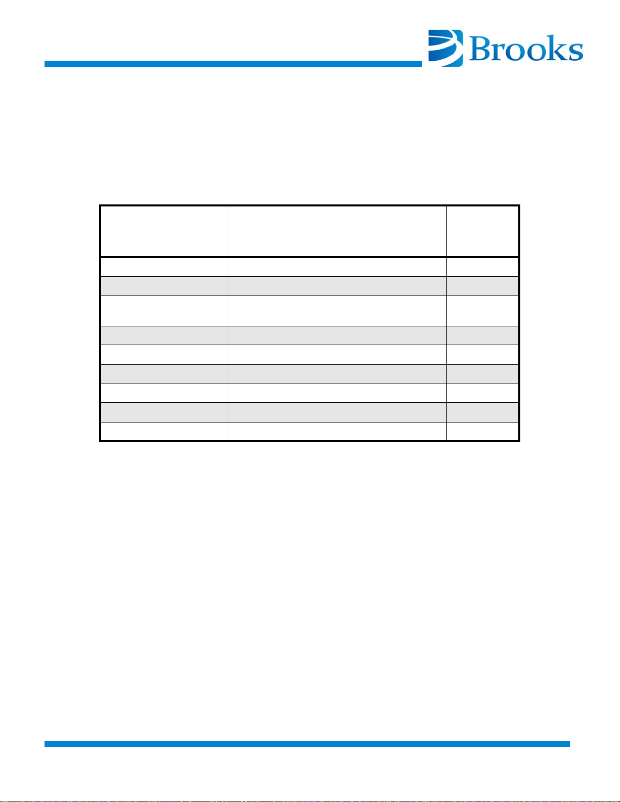
Equipment/Tools Requirements
Read this procedure before attempting to perform the steps.
The following tools and equipment must be available to perform
this decontamination procedure. If you do not have this equipment, refer to Con-
tacting Brooks’ Technical Support in the front of this manual to order the equipment needed.
Table 4-2: Decontamination Tools and Equipment
BROOKS-
CRYOGENICS Part
Number
8080250K003 Maintenance Manifold Kit 1
7021002P001 Charging Hose 1
Description Quantity
8043079G060 Flexline, 5-foot
(acceptable to use longer lines)
- Ultra Pure Helium (99.999%) -
571716 1-inch Open End Wrench 1
571717 1 1/8-inch Open End Wrench 1
571718 1 3/16-inch Open End Wrench 1
8080015K001 Keypad/display 1
8031403 0-400/0-3000 psig Regulator 1
For best results, BROOKS-CRYOGENICS suggests the use of a dedicated helium
bottle, regulator and charge line which are never separated.
2
©2013 Brooks Automation Inc Part No. 8040491, Rev. AB, 01/11/2013 4-4-3
.
Page 62
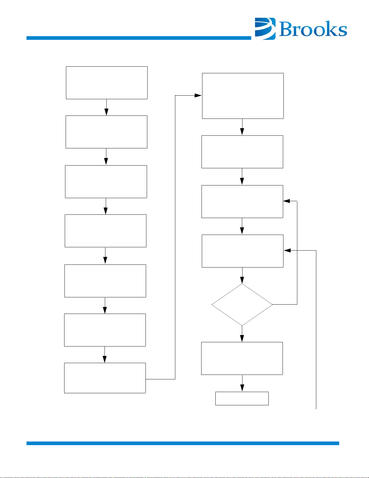
Cool On-Board
Cryopump(s) until
temperature is stable for a
minimum of 30 minutes.
Purge regulator, helium
charging line, and
maintenance manifold
with 99.999% pure helium.
Disconnect helium
SUPPL Y line at coldheads
on same manifold.
Immediately
disconnect helium RETURN
line at coldheads on same
manifold.
Immediately
shut down the On-Board
Cryopump(s).
Warm the
On-Board Cryopump(s) to
300K.
Shut down
compressor
Slowly open ball valve on
maintenance manifold and
depressurize the coldhead
to 30 - 50 psig.
Back-fill coldhead to the
correct static helium
pressure and close Hoke
valve.
Have you
pressurized and
depressurized
5 times?
Yes
No
Go to Page 4-5
Slowly open ball valve on
maintenance manifold and
depressurize the coldhead
to 30 - 50 psig.
Back-fill coldhead to the
correct static helium
pressure.
Step
1
Steps
2,3,4
Step
5
Step
6
Step
7
Step
8
Step
9
Step
11
Step
12a
Step
12b
Step
12c
Step
12d
Connect two 5 foot
flexlines to the
maintenance manifold and
the first On-Board
Cryopump to be
decontaminated.
Step
10
Figure 4-1: Decontamination Flowchart
4-4-4 ©2013 Brooks Automation Inc Part No. 8040491, Rev. AB, 01/11/2013
Page 63
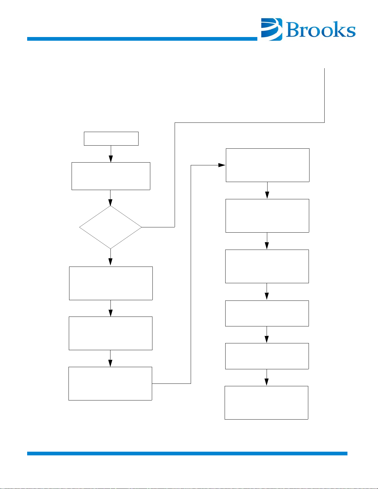
Run coldhead motor for
10 - 30 seconds and
turn motor OFF.
Have you
performed 5
motor drive
cycles?
Yes
No
Verify that the coldhead
has the correct helium
static charge.
Disconnect 5 foot flexlines
from the decontaminated
coldhead.
Connect helium SUPPLY
line at coldheads on same
manifold.
Connect helium RETURN
line at coldheads on same
manifold.
Adjust compressor helium
static pressure to the
correct value.
Restart a Full
regeneration cycle.
Cool On-Board Cryopump
to below 17K.
Repeat Steps 10 - 16 for
each coldhead being
contaminated
Step
12d
Step
13
Step
14
Step
15
Step
16
Step
18
Step
17
Step
20
Step
21
From Page 4-4
Restart Compressor
Step
19
Figure 4-1: Decontamination Flowchart (continued)
©2013 Brooks Automation Inc Part No. 8040491, Rev. AB, 01/11/2013 4-4-5
.
Page 64
Method # 1 - Decontaminate all On-Board Cryopumps
Use this procedure to remove gaseous contamination from the helium circuit by
cooling each On-Board Cryopump so that the gaseous contamination is frozen in
the coldhead. Each On-Board Cryopump is then decontaminated in sequence.
Method 1 is flowcharted in Figure 4-1.
High Gas Pressure
High helium gas pressure is present in high vacuum
pump systems and can cause severe injury from
propelled particles or parts.
Do not modify or remove any pressure relief valve on
the cryopump.
Make sure that the path for the regenerated gas is
unobstructed.
1. Ensure that all On-Board Cryopumps on the same manifold
have been running with second stage below 25K for at least 30
minutes. If not, then cool down the remaining On-Board
Cryopumps and run them for 30 minutes minimum after
reaching 25K to trap contaminants in the coldhead.
a. Continue with Step 2 even if any pump does not cool
below 25K, because its performance may already be affected by
contamination.
b. Close the high vacuum valves to isolate the On-Board
Cryopumps from the vacuum chamber.
When Step 1 is complete, all of the coldheads are cool and the contaminant gases
are frozen in the coldhead.
Steps 2 - 4 are required to ensure that the regulator, charging line and the maintenance manifold will be purged of air and that the air trapped in the regulator will
not diffuse back into the helium bottle. For best results,
BROOKS-CRYOGENICS suggests the use of a dedicated helium bottle, regulator
and charge line which are never separated.
2. Attach a regulator (0-400/0-3000 psig) and charging line to a
helium bottle (99.999% pure). DO NOT OPEN THE BOTTLE
VALVE AT THIS TIME.
4-4-6 ©2013 Brooks Automation Inc Part No. 8040491, Rev. AB, 01/11/2013
Page 65

3. Purge the regulator and charging line as described in Steps a
through d below. Use only 99.999% helium gas.
a. Open the regulator a small amount by turning the adjust-
ing knob clockwise until it contacts the diaphragm, turn the
adjusting knob so that the regulator is barely open.
b. Slowly open the bottle valve, and purge the regulator and
line for 10 to 15 seconds. Keep the helium flowing to prevent
re-contamination.
c. Loosely connect the charge line to the closed Hoke valve on
the maintenance manifold. Refer to
d. Continue to purge the charge line for 30 seconds, and
tighten the charge line flare fitting onto the Hoke valve while
the helium is flowing.
4. Open the ball valve using the extended handle. Open the Hoke
valve. Purge the manifold for 30 seconds, close the ball valve, then
close the Hoke valve.
Once Step 4 has been completed, all of the coldheads are cold, the gaseous contaminant is frozen in the coldhead, the maintenance manifold is filled with clean
helium and connected to the helium bottle.
The helium SUPPLY line should be disconnected first to prevent the crosshead
relief valve from opening.
5. While each On-Board Cryopump is still operating, disconnect the
helium SUPPLY line at all of the coldheads on the same manifold.
The On-Board Cryopump helium supply line is shown in
2.
Figure 4-3.
Figure 4-
NOTICE
Be sure to use two wrenches to ensure that the self sealing
coupling adapter does not back out during disassembly. Refer to
Figure 4-4.
6. Immediately after Step 5, and while each On-Board Cryopump is
still operating, disconnect the helium RETURN line at all of the
coldheads on the same manifold. The On-Board Cryopump helium
return line is shown in
©2013 Brooks Automation Inc Part No. 8040491, Rev. AB, 01/11/2013 4-4-7
.
Figure 4-2.
Page 66
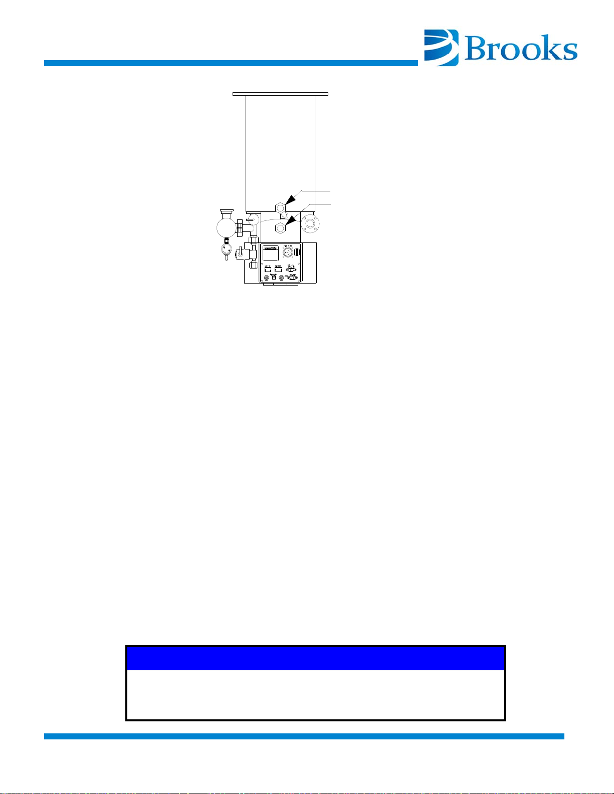
Figure 4-2: On-Board Cryopump Helium Supply and Return Lines
Helium Supply Line
Helium Return Line
7. Immediately after Step 6, shut down all of the On-Board
Cryopumps as described in the appropriate On-Board Module
Programming and Operation Instructions manual.
8. Warm the On-Board Cryopumps to 300K as follows:
a. Regenerate each On-Board Cryopump to be decontami-
nated by pressing the REGEN button, followed by 1 then 2 on
the Network Terminal keypad.
b. When the pumps reach 300K, discontinue the regeneration
cycle by pressing REGEN and 0. Repeat this process on each
pump.
After Step 8 has been completed, all of the coldheads have been cooled and the
contaminant gases frozen in the coldhead. Helium gas lines have been disconnected at the coldheads, and the coldheads warmed up to 300K. The next step is
to remove the contaminant from each coldhead in sequence.
9. Shut down the compressor.
10. Connect the two helium flexlines to the maintenance manifold and
the coldhead of the first On-Board Cryopump to be
decontaminated
NOTICE
Be sure to use two wrenches to ensure that the self sealing
coupling adapter does not back out during disassembly. Refer to
Figure 4-4.
4-4-8 ©2013 Brooks Automation Inc Part No. 8040491, Rev. AB, 01/11/2013
Page 67
11. De-pressurize the coldhead to between 30 and 50 psig (200 and 330
kPa) by slowly opening the ball valve and allowing the helium to
bleed out slowly.
NOTICE
Reducing the coldhead pressure below 30 psig (200 kPa) may
introduce more contaminants into the helium circuit.
12. Perform the following Steps in sequence:
Refer to appropriate Compressor Installation, Operation, and Maintenance
Instructions for the correct static helium charge pressure.
a. Back-fill the coldhead with helium to the correct static
charge pressure by adjusting the regulator to the required pres
sure, and opening the Hoke valve on the manifold. Close the
Hoke valve when the pressure is correct.
b. De-pressurize the coldhead to between 30 and 50 psig (200
and 330 kPa) by slowly opening the ball valve and allowing the
helium to bleed out slowly. Do not reduce the pressure to less
than 30 psig or the coldhead may be further contaminated.
c. Perform the flushing Steps 12a and 12b four more times.
d. Again back-fill the coldhead to the correct static charge
pressure and run the coldhead drive motor for 10 to 30 seconds
by using the remote keypad. Ensure the network cable is
removed and press CONTROL and 1 to turn the motor on.
Press 0 to turn the motor off.
e. Repeat Steps b - d four times. There are a total of 5 drive
motor runs with five flushes each for a total of 25 flushes.
-
Refer to appropriate Compressor Installation, Operation, and Maintenance
Instructions for the correct static helium charge pressure.
13. Verify that the coldhead has the correct helium static charge pressure.
14. Disconnect the 5-foot flexlines from the decontaminated coldhead
supply and return connectors.
15. Reconnect the system helium RETURN line to the return connector
©2013 Brooks Automation Inc Part No. 8040491, Rev. AB, 01/11/2013 4-4-9
.
Page 68

on the coldhead as shown in Figure 4-2.
16. Reconnect the system helium SUPPLY line to the supply connector on the coldhead as shown in Figure 4-2.
Once Step 16 has been completed, the decontamination of the first On-Board
Cryopump is completed and charged to the correct pressure with clean helium.
The remaining coldheads need to be decontaminated.
17. Repeat Steps 10 - 16 for each coldhead being decontaminated.
18. Once Step 17 has been completed, the On-Board Cryopumps are
ready to be cooled down. Adjust the compressor pressure to the
correct charge pressure.
Refer to the appropriate Compressor Installation, Operation, and Maintenance
Instructions for the correct static helium charge pressure value and adjustment
procedure.
The charging adapter can be inserted into any helium line at the tool to simplify
the final adjustment of system pressure. It should be removed after final pressure
adjustment.
19. Restart the compressor.
20. Start a Full Regeneration cycle on all the On-Board Cryopumps to
prepare the vacuum side of the On-Board Cryopump.
21. Allow the On-Board Cryopumps cryopumps to cool to below 17K.
If ratcheting in the On-Board Cryopump reappears, refer to Contacting Brooks’
Technical Support in the front of this manual for additional technical assistance.
Decontamination Alternatives
Method # 1 is the most effective procedure for removing gaseous contaminants
from the helium circuit. By this method, all On-Board Cryopumps are first cooled
down and the contaminant frozen. Each On-Board Cryopump is decontaminated
in sequence.
If time is critical, then Method # 2 is an alternate procedure for decontamination.
This procedure will also remove gaseous contaminant in the system.
4-4-10 ©2013 Brooks Automation Inc Part No. 8040491, Rev. AB, 01/11/2013
Page 69

Method # 2 Decontamination of Only Cold Cryopumps
Method # 2 is based on Method # 1.
If certain On-Board Cryopumps are warm in Step 1 then they can remain at room
temperature (i.e. over 290K). With the compressor on and cold
On-Board Cryopumps left on, run these “warm” On-Board Cryopumps for 5
minutes. Running these “warm” On-Board Cryopumps for a short time will move
any concentrated contaminant out of these coldheads into the compressor. The
contaminants will then be carried to the cold On-Board Cryopumps where they
will be frozen.
In Method # 2, the following Steps replace the corresponding Steps in Method #
1:
Step 1 - Method # 2
Any On-Board Cryopumps on the same manifold which are running should have
been running below 25K for at least 30 minutes. Any pumps warmer than 290K
should be kept warm.
a. Continue with Step 2 even if any pump does not cool
below 25K (its performance may already be affected by con
tamination).
b. Close the high vacuum valves to isolate the On-Board
Cryopumps from the vacuum chamber.
Step 17 - Method # 2
Repeat Steps 10 - 16 for each On-Board Cryopump which is not above 290K.
Method # 3 Grouped Decontamination Using Manifold
Method # 3 is based on Method # 1.
The time required to decontaminate each On-Board Cryopump in Method #1
after it is cooled and warmed up is about 30 minutes. If time is not available to
decontaminate each On-Board Cryopump in sequence, then the alternate is to
decontaminate all On-Board Cryopumps together; in other words, Grouped Decon-
tamination. At least one of the On-Board Cryopumps must be cold. The decontamination is performed from the compressor side of the common supply and
return manifolds.
-
In Method # 3 the following Steps replace the corresponding Steps in Method # 1.
©2013 Brooks Automation Inc Part No. 8040491, Rev. AB, 01/11/2013 4-4-11
.
Page 70

Step 5 - Method # 3
While each On-Board Cryopump is still operating, disconnect the helium SUPPLY line at the compressor side of the common supply manifold at the tool.
Step 6 - Method # 3
While each On-Board Cryopump is still operating, disconnect the helium
RETURN line at the compressor side of the common supply manifold at the tool.
Step 10- Method # 3
Verify that the compressor is off. Connect the two 5-foot helium flexlines to the
maintenance manifold and the compressor side of the common supply and return
manifold.
NOTICE
Be sure to use two wrenches to ensure that the self sealing
coupling adapter does not back out during disassembly. Refer to
Figure 4-4.
Steps 11 - 16 - Method # 3
All connections are to the manifold, not the individual coldheads. All coldhead
drive motors are to be run for 10 to 30 seconds using the remote keypads per Step
12d. At the end of Step 16, all of the On-Board Cryopumps are decontaminated.
4-4-12 ©2013 Brooks Automation Inc Part No. 8040491, Rev. AB, 01/11/2013
Page 71
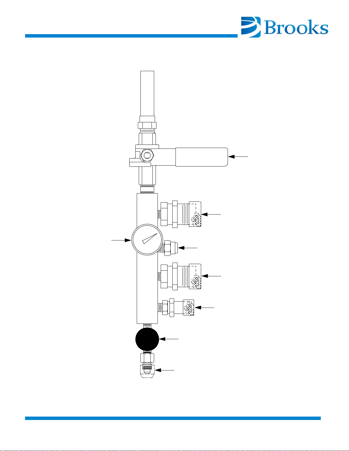
Helium Flex Line Connection
Helium Pressure Gauge
Ball Valve
99.999% Helium Connection
Helium ON/OFF (Hoke) Valve
Relief Valve
Helium Flex Line Connection
Helium Flex Line Connection
Figure 4-3: Maintenance Manifold Part Number 8032051G001
©2013 Brooks Automation Inc Part No. 8040491, Rev. AB, 01/11/2013 4-4-13
.
Page 72
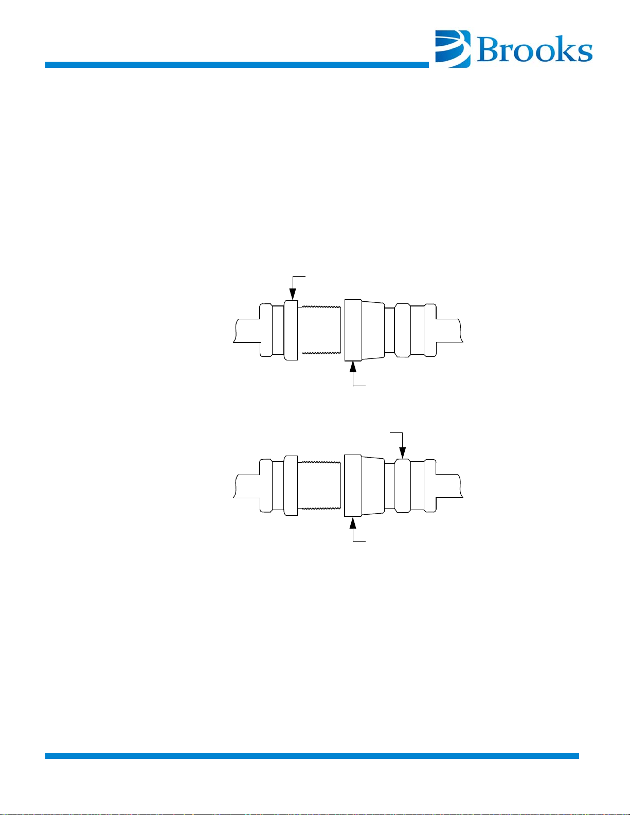
TO CONNECT
Hold here using 1-inch wrench
Turn here using 1 3/16-inch wrench
Hold here using 1 1/8-inch wrench
Turn here using 1 3/16-inch wrench
COUPLING HALVES
TO DISCONNECT
COUPLING HALVES
Figure 4-4: Proper Helium Line Coupling Disconnection/Connection
4-4-14 ©2013 Brooks Automation Inc Part No. 8040491, Rev. AB, 01/11/2013
Page 73
On-Board Cryopump Cleaning
Toxic and/or corrosive process gases or liquids
pumped or captured by an On-Board, On-Board IS, or
Cryo-Torr product could cause severe injury on contact.
Always vent toxic/corrosive gases or liquids to a safe
location using an inert purge gas.
The customer is responsible for safely exhausting
these gases.
Clearly identify on the cryopump which toxic/corrosive
gas or liquid is contained in the pump before storing or
shipping it to Brooks Automation.
Cleaning the arrays or other interior surfaces of the On-Board Cryopump vacuum
vessel is seldom required because dust buildup does not affect performance, and
the special copper alloy cryo-condensing arrays are nickel plated for corrosion
resistance.
Toxic/Corrosive Gases
When cleaning the arrays and other interior surfaces, do the following:
1. Confirm that an adequate supply of indium gasket material, P/
N 7100001G006, is available to replace gaskets inadvertently
damaged during disassembly.
2. Carefully disassemble the components in the vacuum vessel,
including the arrays and radiation shield, to avoid damage to the
indium gaskets.
3. Clean the interior surface of the vacuum vessel, the 80K condensing array, and the 80K radiation shield as follows:
a. Wash each item in strong soap or detergent solution and
hot water.
b. Rinse the items in clean hot water.
c. Air or oven dry all items at 150° F (66° C) maximum before
reinstalling into the On-Board Cryopump
©2013 Brooks Automation Inc Part No. 8040491, Rev. AB, 01/11/2013 4-4-15
.
Page 74

NOTICE
Do not clean the 15K cryo-adsorbing array because you may
severely contaminate the adsorbent in the cleaning process.
4. Wearing lint-free gloves, reassemble the On-Board Cryopump.
5. Replace any indium gasket damaged during disassembly.
4-4-16 ©2013 Brooks Automation Inc Part No. 8040491, Rev. AB, 01/11/2013
Page 75

Index
A
Auxiliary TC gauge installation, 2-11
C
Cold head, 1-19
Coldhead, 4-2
Compressor gas and oil flows, 1-19
D
Decontaminating
alternatives, 4-10
cold cryopumps, 4-11
tools required, 4-3
using manifold, 4-11
Decontaminating the circuit, 4-1
H
Helium circuit decontamination, 4-1
Helium line connections, 2-10
I
Installation
introduction, 2-1
K
Keypad
remote operations, 1-2
Keypad and display
installation, 2-2
Keypad and display installation
position A, 2-2
position B, 2-3
position C, 2-4
position D, 2-5
M
Maintenance, 4-1
Microprocessor control
On-Board Cryopump, 1-1
©2013 Brooks Automation Inc Part No. 8040491, Rev. AB, 01/11/2013 Index-1
.
Page 76

O
P
On-Board 10 Cryopump
specifications, 1-12
On-Board 10F Cryopump
specifications, 1-13
On-Board 250F Cryopump
specifications, 1-14
On-Board 250FH Cryopump
specifications, 1-15
On-Board 4 Cryopump
specifications, 1-6, 1-7
On-Board 400 Cryopump
standard capacity specifications, 1-16
On-Board 400 High Capacity Cryopump
specifications, 1-17
On-Board 500 Cryopump Installation, 2-7
On-Board 6 Cryopump
specifications, 1-8
On-Board 8 Cryopump
specifications, 1-9
On-Board 8F Cryopump
enhanced specifications, 1-11
specifications, 1-10
On-Board Cryopump
microprocessor control, 1-1
On-Board cryopump
cold head, 1-19
compressor gas and oil flows, 1-19
theory of operation, 1-19
vacuum vessel and arrays, 1-19
On-board cryopump
description, 1-1
installation, 2-6
On-board cryopump installation
auxiliary TC gauge installation, 2-11
helium line connections, 2-10
purge gas connection, 2-10
rough valve gas connection, 2-10
roughing pump connection, 2-10
vent pipe connection, 2-9
On-board cryopumps
decontaminating, 4-6
Purge gas connection, 2-10
R
Remote keypad and display installation, 2-12
Remote operations, 1-2
Rough valve gas connection, 2-10
Roughing pump connection, 2-10
S
Safety precautions, S-1
Setpoint relays
connecting, 2-11
Specifications
On-Board Cryopump, 1-6, 1-7, 1-8, 1-9,
1-10, 1-11, 1-12, 1-13, 1-14, 1-15,
1-16, 1-17
T
Troubleshooting, 3-1
V
Vacuum vessel and arrays, 1-19
Vent pipe connection, 2-9
Index-2 ©2013 Brooks Automation Inc Part No. 8040491, Rev. AB, 01/11/2013
 Loading...