

Page 1

SYSTEM MANUAL
FT1-SB
Single Zone
Fire Alarm System
Page 2

FT1-SB System M an u al
1
MA370 I ss . 1
DOCUMENT HIST ORY
Issue Date Description Written B y Checked By
Draft 0 2/9/2008 Original Document. A. She no uda C. Orr
Issue 1 4/11/2011 Update drawing in figure 7 A. She no uda A. She no uda
Page 3

FT1-SB System M an u al
2
MA370 I ss . 1
INDEX
1 INTRODUCTION ........................................................................................................................ 4
1.1 Import an t Information ........................................................................................................... 4
1.2 System Overview ................................................................................................................. 4
1.3 Features ............................................................................................................................... 5
2 OPERATION .............................................................................................................................. 6
2.1 Front Display Module ........................................................................................................... 6
2.2 Termina t ion and Co nt r ol Modul e ......................................................................................... 7
2.3 Power S upply ....................................................................................................................... 8
2.4 FT1-SB I ndi cations .............................................................................................................. 9
2.4.1 LED flas h funct ions .......................................................................................................... 9
2.4.2 Buzzer I ndic ati ng Patt ern ................................................................................................. 9
2.4.3 Control F u nct ions ...........................................................................................................10
2.4.4 Control O utputs ..............................................................................................................10
2.5 Zone Input ..........................................................................................................................11
2.6 FT1-SB S pecification .........................................................................................................13
3 INSTALLATION AND COMMISSIONING................................................................................14
3.1 Installation ..........................................................................................................................14
3.1.1 FT1-SB I ns t al l ation .........................................................................................................14
3.1.2 Wiring .............................................................................................................................16
3.1.3 Visual inspection.............................................................................................................16
3.2 Commissioning ..................................................................................................................16
3.2.1 Power ON .......................................................................................................................16
3.2.2 Alarm & F a ul t Test (T est contr ol s )..................................................................................16
3.2.3 Actual Test......................................................................................................................17
4 PRODUCT GUARANTEE ........................................................................................................18
Page 4

FT1-SB System M an u al
3
MA370 I ss . 1
FIGURE LIST
Figure 1 FT1-SB Display ................................................................................................................... 6
Figure 2 FT1-SB Control & Termi nat ion Module ............................................................................... 7
Figure 3 D in rail P ower supply ........................................................................................................... 8
Figure 4 Ty pi cal Relay or Sounder Control Ci r c uit ..........................................................................11
Figure 5 Zone Inp ut C i r cuit ..............................................................................................................12
Figure 6 FT1-SB Bl ock Wiri ng Diagr am ........................................... Error! Bookmark not defined.
Figure 7 C o ntr ol / Termina t ion Modul e & Power S upply moun t ing .................................................15
Figure 8 FT1-SB Front Display t y pical mounting .............................................................................15
TABLE LIST
Table 1 FT1-SB LED Indic ati ng Pa tter ns .......................................................................................... 9
Table 2 FT1-SB Bu z zer Indica ti n g P attern ........................................................................................ 9
Table 3 FT1-SB Co ntrol Butt ons .....................................................................................................10
Table 4 Z o ne Input Cir cuit Spec ificatio ns ........................................................................................11
Table 5 C ompatible Actuatin g Devices ...........................................................................................12
Table 6 FT1-SB General Specifications ..........................................................................................13
Page 5

FT1-SB System M an u al
4
MA370 I ss . 1
1 INTRODUCTION
1.1 Important Information
The Brooks Firetracker FT1-SB is single zone conventional fire alarm panel with compatible
smoke and/or heat detectors and auxiliary devices, it provides a complete single zone automatic
fire detection and alarm system. FT1-SB has been designed to comply with the Australian
standard AS7240.2 and for specific use in non critical switchboard applications such as main
switch bo ar ds and m ot or control panels .
FT1-SB co ns i sts of 3 b as i c modules :
1. Display Module, provides the user interface to control and monitor the FT1-SB system.
The display module is designe d to be mounted on the front door of a switch board and
utilizes the standard square cut-out 90 x 90 m m in any switch board door cabinet. This
provides full control of the system without needing to enter the panel and avoid exposure
to liv e p ar ts
2. Termina t ion Module is house d i n a DIN rai l enclosur e a nd mounted on the eq ui pment gear
tray inside the switch board cabinet. All detector termination and auxiliary outputs are
availabl e on the ter m ination m odule. O nly 4 w ir es are required t o i n t erface t he fr on t di splay
module to the termination module allowing flexibility of mounting location within the
switchb o ar d cabine t.
3. Power supply, is a DIN rail mounted module and for installation beside the termination
module.
1.2 System Overv iew
Brooks FT1-SB is designed for those switchboard applications where fire detection is required
within the switchboard cabinet itself rather than protecting the room within which the switchboard
is located. The design of the system allows for the utilization of the same techniques as originally
used i n t he switch b oar d d es i g n i t s elf, i.e. standar d m eter case for m at and DIN rail m o unting.
The system monitors continuously the zone circuit for normal, alarm and faults (short or open
circuit). The system provides alarm, fault and disable (isolate) voltage free contacts and a ful ly
supervised 24V dc switched output to initiate external ancillary devices as well as provide an input
to local sy stem moni toring such as a building management sy s tem.
FT1-SB system utilizes a non battery backed 24V dc power supply. The din rail switch mode
power supply provided with the system has a wide range of mains input voltages and an
adjust abl e 2 4V DC out pu t .
Page 6

FT1-SB System M an u al
5
MA370 I ss . 1
1.3 Features
The Brooks FT1-SB utilizes the lea di n g edge t echnology :
• Microprocessor based system in both di splay a nd termination modul e s .
• Easy to install, standard m e t er enclosure D IN rail t ermination modul e and power supply
• Intuitive i n di ca t ion and c ontrols, high intensity LED in dicat ors and pushbutton switches.
• T r ansparent protectiv e cover for t he displa y m o dule.
• Fully su p ervised detector circ uit.
• One su p er v is e d alarm o ut pu t li m i te d to 0.5 Am p.
• Two alarm changeover rel ay c ontacts rated to 240VAC @ 5Amp an d 24 VD C @ 0.5Amp.
• T w o faul t chang eover rel ay c ontacts.
• One disable (isolate) c ha n ge ov er relay co ntact.
• U ni ver sal AC i np ut DIN rail switch mode power supply 240VAC / 24VDC @ 1Amp
Page 7
FT1-SB System M an u al
6
MA370 I ss . 1
2 OPERATION
2.1 Front Display Module
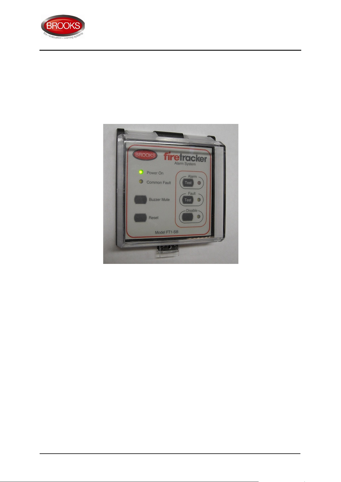
The front display of Brooks FT1-SB is shown in Figure 1.
Figure 1 FT1-SB Display
The front display of FT1SB compromises indicators and controls for all system functions. The
alarm zone facility is segregated and includes a separate control and LED indicator for each
function, i.e. alarm test, fault test an d disa ble (isola te) .
A ‘Power O N’ and ‘Common Fault’ indicators are provided to indicate that the mains power is
applied and to identify if a system fault is pr esent (s ee Table 1)
FT1-SB provides a mute facility to silence the panel buzzer. Any new event, al ar m or faul t, will reactivat e the b uzzer .
A reset control is also pr ov ided to reset any l atc hed a larm or faul t condition.
Page 8
FT1-SB System M an u al
7
MA370 I ss . 1
2.2 Terminati on an d Contr ol M odule
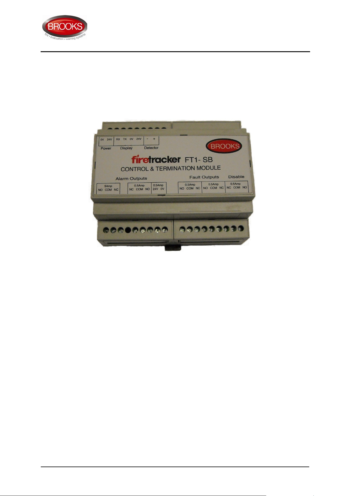
The Termination & Control Module of Brooks FT1-SB is shown in Figure 2.
Figure 3 FT1-SB Termination & Control Module
The contr ol and ter mi nati on modul e should be m o unted o n a D I N r ai l ins tal le d at a conv eni ent
locati on w it hin the sw i tchboard cabine t. The co ntrol and ter m i n ation mod ul e as shown Figure 3
provides the term inati on poi nt for all the field wiring. It is connected t o the fro nt dis play via 4 wir es,
2 of the s e ar e used to supply 24 V d c ( 0 V & 24V) a nd the oth er two for communi cations via RS23 2
(Rx & Tx).
Page 9
FT1-SB System M an u al
8
MA370 I ss . 1
2.3 Power Supply
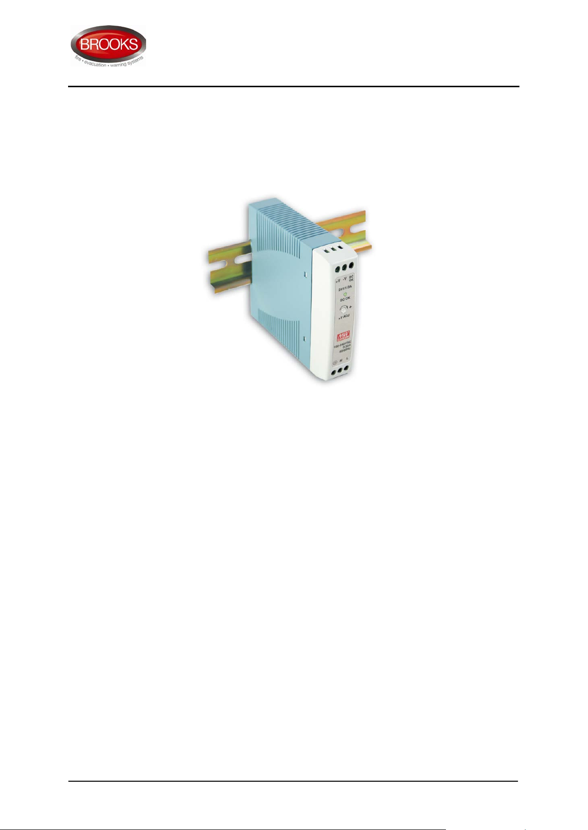
Brooks FT1-SB is powered by a DIN rail switch mode power supply as shown in
Figure 4 below
Figure 4 Din rail Power supply
Features:
• U ni ver sal AC i np ut
• Short circ uit / Ov er l oa d / O v er voltag e Protections
• C an be install e d on a 3 5m m DIN rail
• LED indic at or for power on
• N o l o ad power consumption
• C urr ent Ra nge 0-1A
• +/-10% voltage adjustment
• 84% effici e nc y
• AC c ur rent consumpti on 0.35A @ 240V
• C om pl i es w i th s a fety, EM S im m uni ty and EMI stan d ar ds
Page 10

FT1-SB System M an u al
9
MA370 I ss . 1
2.4 FT1-SB Indications
The de fa ult st a te of the L ED i n di ca t or s and the buzzer is OF F if it i s not defined below.
2.4.1 LED flash functions
The FT1-SB LED indic at ors use the foll owi ng flash pattern to signal the system conditions.
Table 1 FT1-SB LED Indic atin g Patter ns
Indicators Pattern Function
Power On Steady On Power On
Zone Al ar m
Zone F aul t
Flashing
Steady on
Flashing
Steady
Alarm Test
True Alarm
Fault Test
Open or shor t cir cuit fault
Zone Disable Steady Zone outp uts di sabl ed
Memor y Faul t
Common Fault Steady on
Communic ati on Fa ult
Monitor e d Output F a ul t
Zone F aul t
2.4.2 Buzzer I ndicatin g Patter n
Table 2 FT1-SB Buzzer Indicating Pattern
Function Pattern
Alarm Continuous sound
Fault Pulsing one pulse every 3 seconds
Mute One pulse only to sil enc e th e buzz er
Any Key One pulse for every bu tto n press ed
Page 11

FT1-SB System M an u al
MA370 I ss . 1
2.4.3 Control Func tions
Table 3 FT1-SB Control Buttons
Control Condition Description
Buzzer Mute Buzzer Off
Reset System r es et ting
Alarm LED flashes once
Alarm Test
every sec ond.
All alarm outputs active
Fault LED flash es on ce
Fault T es t
every sec ond
Fault relay activate
Disable Disable LED Steady on
Silences the panel buzzer unti l a new f ault or
alarm occurs
Reset active alarm or fa ul t
Disable active te s t mode.
Note: If alarm or fault co ndi tion stil l ac ti ve ,
the alar m or fault will re-activate
Perform z o ne alarm t es t. It takes
approxim at ely 3 secon ds for th e alar m
condition to b e d etected a nd verifi ed befor e
the alarm relay s and buz zer bec ome acti v e
Perform z o ne fault t est . It takes
approxim at ely 3 secon ds for th e faul t
condition to b e d etected a nd verifi ed befor e
the faul t r el a y a nd b uz zer bec om e ac ti ve
Disable all alarm or faul t outputs
Energis e di s able rel ay
Zone alar m or faul t LED rem ains ill um inat ing
2.4.4 Contr ol O utpu ts
Non-supervised outputs
The non-supervised outp uts include the foll ow i ng .
• Al ar m conditio n r elay ou tp ut, 2 sets o f c ha ngeover voltage contacts
• F aul t c o ndition r elay outp ut , 2 sets o f changeo v er v oltage contacts
• D i sabl e c o n di ti o n r elay ou tp ut. 1 set of changeover voltage contacts
10
Page 12
FT1-SB System M an u al
MA370 I ss . 1
Supervised Output
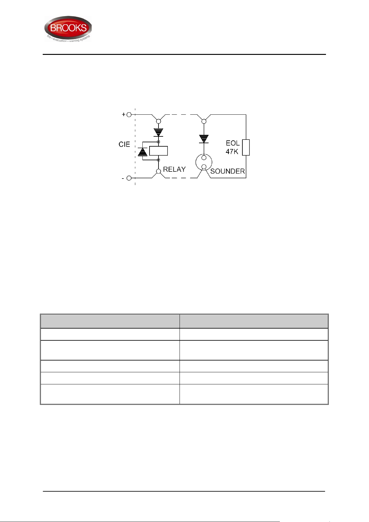
FT1-SB provides one supervised output protected with 1 Amp fuse. External relays, sounders, or
strobes, shal l b e connected as shown in Figure 5
.
Figure 5 Typical Relay or Sounder Control Circuit
If the supervised output is not used, the EOL resistor shall be installed on the output terminals on
the control / termination mod ul e . The EOL r esi s t or type is 4 7K, 1/2 W or 1 W, 1%, metal fil m .
2.5 Zone Input
The zone input speci fications a nd c ompatible devices ar e listed in tabl e 5 and t able 6.
Table 4 Zone Input Circuit Specifications
Item Description
Number o f detector s p er zone 0 – 40, includin g MCPs if any
Number o f detector s i n alarm st ate
Zone c ur r en t limit 42mA
Typical Zone q ui escent c ur ren t per z one 6mA
Typical z o ne i n put resistance in alarm
conditio ns per zone
Up to 2 d et ec t or s i n cl u di n g MCPs, heat and
smoke detectors.
560 Ohm
11
Page 13
FT1-SB System M an u al
MA370 I ss . 1
Table 5 Compatible Actuatin g Devices
Part No. Manufacturer Description
4350 Panasonic Conventio nal mul ti det ect or
4352 Panasonic Conventional photoelectr i c s moke detector
6295 Panasonic Conventio nal en c l os ed heat d et ec t or 60 degre es
6296 Panasonic Conventio nal en c l os ed heat d et ec t or 80 degre es
6297 Panasonic Conventio nal en c l os ed heat d et ec t or 100 degr ees
6298 Panasonic Conventio nal en clos ed heat det ec t or 1 20 degree s
4318 Panasonic Conventio nal com bi nati on he at detec tor
MRCSRR Menvier Red MCP complete with 470 / 680 Ohm al arm resi stanc e.
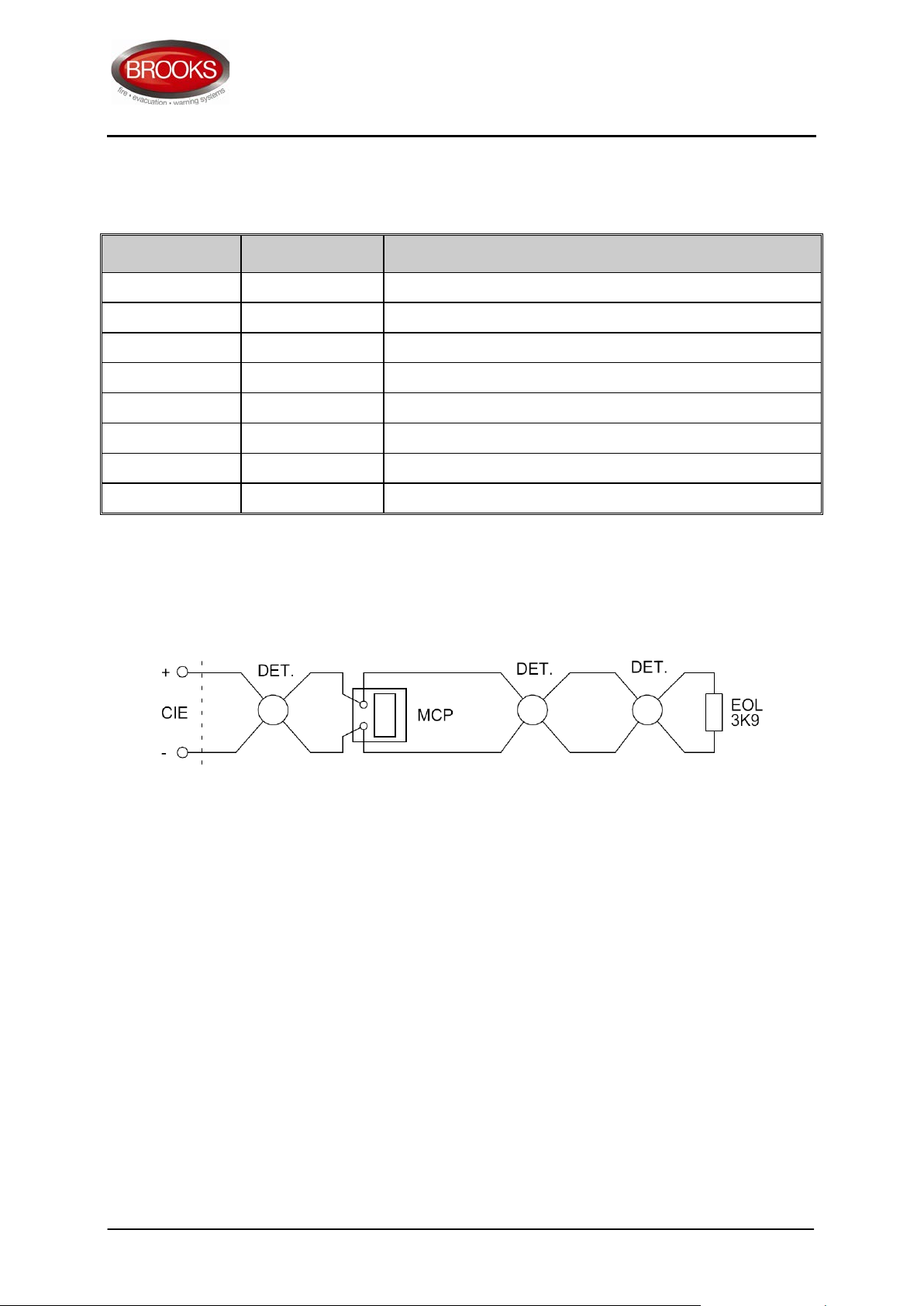
The typical zon e input c i r cui t i s shown in Figure 6
.
Figure 6 Zone Input Circuit
If a zone input is not used, an EOL resistor shall be installed. Otherwise a fault condition will
always b e gener ate d. Th e zone EOL resis tor typ e is 3k9, 1 W, 1%, metal film.
12
Page 14

FT1-SB System M an u al
MA370 I ss . 1
2.6 FT1-SB Specification
Table 6 FT1-SB General Specifications
Feature Specification
Mains P ower Suppl y
Current C o nsumption
Cable L en gth
(between displ ay & Term.)
Input 8 5-264V AC, 120-270VDC
Output 24VDC adj us t a bl e +/- 10%. 20 Watt, 1Amp
Nominal 50mA
Alarm 150mA
Up to 3 metres
Operating Temp er a ture 0°C to +50°C.
Operating Humi dity 5-95%, non-condensing.
IP Rating IP31
End of Line Resistor
Detector Circ uit 3k 9
Supervised Ou tput 47k
Display Module - 96mm x 96mm x 72mm (H/W/D)
Dimensions
Termination Module - 90mm x 106mm x 58mm (H/W/D)
Power S upply – 90mm x 22mm x 100mm (H/W/D)
13
Page 15
FT1-SB System M an u al
I
+
47K
+
-
DET.
C
680
DET.
POWER SU PPLY
24V / 1A
A
N
V+
V-
POWER
MCP
EOL
3K9
24V
0V
24V24V
0V0V
TX
TX
RXRX
DISPLAY
DETECTOR
SUB930
SUB931/931S/932
FT1 - SB
DISPLAY MODULE
FT1 - SB
CONTROL MODULE
240V AC
NO
NC
COM
NO
NC
COM
NO
COM
NC
NO
COM
NC
NO
COM
NC
DISABLE
CONTACT RATING
0.5A @ 24V DC
24VDC / 0.5 Amp
SUPERVISED
CONTACT RATING
0.5A @ 24V DC
CONTACT RATING
0.5A @ 24V DC
CONTACT RATING
0.5A @ 24V DC
CONTACT RATING
5A @ 24VDC / 240VAC
ALARM
OUTPUTS
FAULT
OUTPUTS
N
MA370 I ss . 1
3 INSTALLATION AND COMMISSIONING
This chapter provides the CIE installation and commissioning guidelines. The installation and the
commissioning of Brooks FT1-SB shall be carried out in accordance of AS3000. For detector
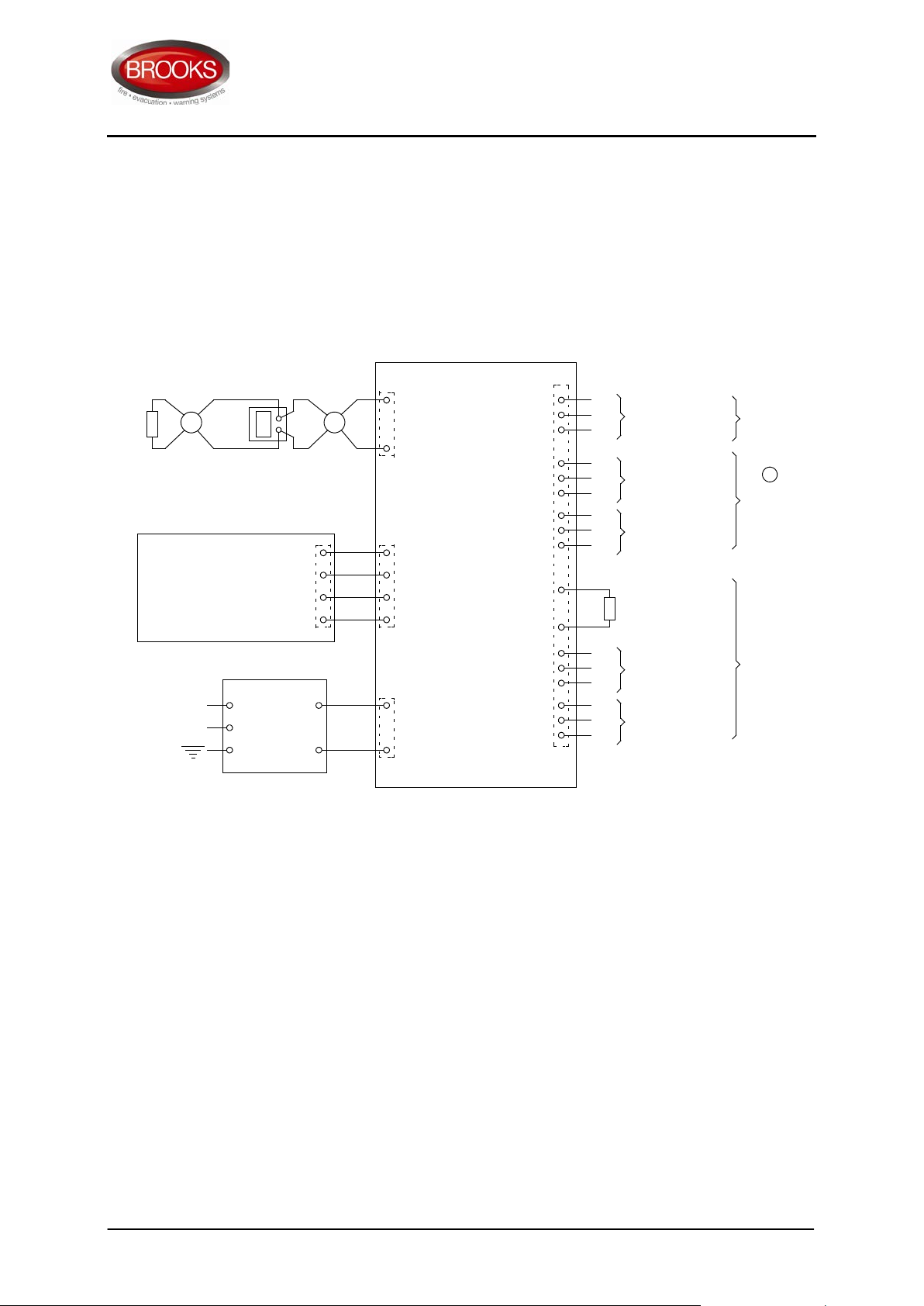
selection and location refer AS1670.1 2004 Appendix A. The block wiring diagram of FT1-SB is
shown in fi gur e 7
Figure 7 FT1-SB Block Wiring Di agram
3.1 Installation
3.1.1 FT1-SB Installation
1. The control / termination module and the power supply are designed to be rail mounted.
2. The display module shall be mounted via a standard 90x90mm square cut out on the
3. Be for e the installation is complete, check and secure all the elec tr i cal connectio ns .
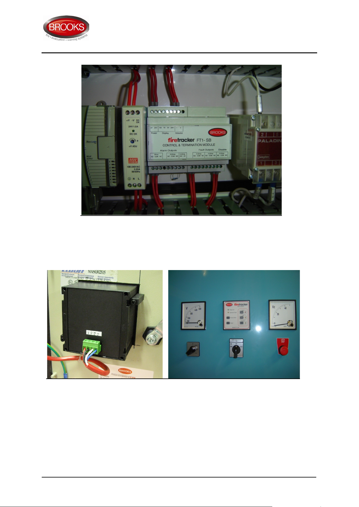
These units can be installed at any convenient location within the switchboard cabinet and
connec ted to th e displ ay mod ule via 4 c ores as sown in Figure 8.
front door o f a switch board. Pl e ase r efer to the mech ani cal drawing o f th e sys t em
cabinet as shown in figure 9
14
Page 16
FT1-SB System M an u al
MA370 I ss . 1
Figure 8 Control / Termination Module & Power Supply mounting
Rear Fron t
Figure 9 FT1-SB Front Display typical mounting
15
Page 17

FT1-SB System M an u al
MA370 I ss . 1
3.1.2 Wiring
The wiring of FT1-SB shall be according to the block wiring diagram shown in figure 7.
3.1.3 Visual inspection
Full fu nctional te s ti n g a n d v i su al c h eck have been carri ed o ut i n the fac tor y before despatchi ng the
FT1SB System. Upon completion of installation and prior to applying power a visual inspection
should be carried o ut to ensure:
• All detec tor s are c on nected with the corr ect pol ari ty.
• End of Line resis tor 3K9 is fitted in the l ast de tec tor o r MC P.
• Where the supervised output is used, the end of line resistor 47K is fitted as shown in
Figure 5.
• The conn ecti on of mains power t o the power supply is correctly terminated.
3.2 Commissioning
3.2.1 Power ON
The Pow er ON Procedures shall b e carrie d ou t durin g on-site com m i s si oning as follow:
1. Turn ON the circuit breaker that connects mains power to FT1-SB power supply. Check
that the green mains “O N” LED on the power s u p pl y module i s i l l um inated.
2. On the front Display check that only the green ‘Power ON’ LED is illuminated, all o ther
LED indi c ators s ho ul d b e e x ti n gui shed
3. Measure the DC voltage on the power supply output between +V and -V. The voltage
shall be 24Vdc +/- 0.2V. If the voltag e requires adjustment, loc ate th e “+V ADJ ” trim pot on
the front of the power supply module and adjust until the measured voltage is within
tolerance.
3.2.2 Alarm & Fault Test (Test controls)
FT1-SB fro nt displ ay pr ovid es 3 contr ols ; alarm tes t, faul t test an d disabl e. T he alarm test an d faul t
test pr oc e dures may b e carrie d o ut as follow:
1. Press t h e al ar m t es t c o ntrol button an d check:
• Alarm LED is flashing
• Buzzer is On
• Alarm relay s en er gi sed and su per v i s ed outpu t i s active
2. Press th e Silen ce Bu zzer c ontr ol, the buzz er sh all stop so undi ng.
3. Press Dis abl e, all al arm outp uts de-activ at e, t h e alarm LED remains fl ashing
4. Press th e “Reset ” b utton , alar m rel ays de-energise and the alar m LED exti ngui sh es
5. Re-Press the ‘D isable” c o ntrol to re enable the system.
6. Press t h e fault test button a nd c h ec k t h e fol l ow ing:
• Fault LED is flashing
• Buzz er is On
• F aul t r el a y is de-energised
7. Repeat s tep 2 – 5 for f ault condi tio n
16
Page 18

FT1-SB System M an u al
MA370 I ss . 1
3.2.3 Actual Test
Al arm Tes t
1. Using an aerosol smoke simulation spray, spray each smoke detector in turn and
check the foll owi ng:
• Al ar m L ED i l l uminates steady
• Buzzer is steady On
• Al ar m r elays on th e Control / Termin ation M odule are en er gized
• Supervised alarm output is active (24V on the terminal)
2. Press “Silence Buzzer” control, buzzer would si lence.
3. Press “Reset” control, alarm relay s de-energis e an d the alarm LED extin guis hes
Fault Test
1. Remove the last detector in the circuit (EOL) to sim u l ated zone open cir c uit a nd check
the following:
• Zon e fault LED and com m o n fault L ED Illuminate steady
• Buz zer is puls ing once every 3 seconds
• F aul t r el a y o n t h e C o ntrol / Ter m i n ati o n Module is de -energized
2. Press “Silence Buzzer” control, buzzer would si lence.
3. Re fit the det ector , check that the faul t LED r em ains ill um i nat e d.
4. Press “Reset” control, fault LED exting uish es
Disab le Test
1. Press di s a bl e control, ensure di s able LED i ll um inates
2. Carry out an ALARM TEST as per 3.2.2, ensure the alarm LED illuminates but the
alarm o ut puts do n ot fu nc tion.
3. Carry out an FAULT TEST as per 3.2.2, ensure the fault LED illuminates but the fault
outputs do not fu ncti on .
4. Re press th e disa ble co ntrol to re-enable the syst em .
17
Page 19

FT1-SB System M an u al
MA370 I ss . 1
4 PRODUCT GUARA NTEE
Brooks guarantees the FT1-SB control and indicating panel for a period of either fifteen (15)
months from the date of purchase or twelve (12) months from the date of installation, whichever
is the lesser. If a product has any defect due to faulty workmanship or material it will upon return
to Brooks be repair ed or replaced free of charge.
If FT1-SB panel, any smoke/heat detectors or any other equipment supplied by Brooks should
become defective within the guarantee period, it must be returned to Brooks, with proof of
purchase, carefully packaged, with the problem clearly stated. Brooks shall at its discretion repair
or replace the faulty unit. If returning the complete product all accessories and documentation
MUST be returned.
This guarantee only applies to normal conditions of use and service, and does not cover damage
caused to the product or its components as a resulting from accident, neglect, misuse,
unauthorized dismantling, or contamination howsoever caused, incorrect installation, careless
handling or where repairs have been made or attempted by others. Onsite warranty repairs are
not part of this guarantee. This guarantee excludes incidental and consequential damage. This
guarant e e do es n ot c ov er costs associated w i th the removal and /or install ation of equipment
No other guarantees written or verbal are authorised to be made on behalf of Brooks. All other
conditions and warranties whether expressed or implied are, to the extent permitted by law,
hereby excluded.
As Brooks has no control over the system's design, installation to the relevant Australian
Standard or maintenance, the Company and its agents take no responsibility for any damage,
financial loss or injury caused to any equipment, property or persons resulting from the use of
the FT1-SB syst em
Do not interfere with any components of FT1-SB system or attempt to tamper with it. This will
invalidate the guarantee, but more importantly may expose the user to shock or fire hazards. This
guarant e e i s i n addition t o your stat utory rig ht s as a consumer .
18
Page 20

FT1-SB System M an u al
MA370 I ss . 1
Head Office
New South Wales / Australian Capitol Territory
4 Pike Street, Rydalmere. 2116
Phone: 61 (0)2 9684 1466
Facsimile: 61 (0)2 9638 7700
E-mail: [email protected]
Regional Offices
Victoria / Tasmania
1/3 Molan Street, Ringwood 3134
Phone: 61 (0)3 9879 5294
Facsimile: 61 (0)3 9879 5249
E-mail: [email protected]
South Australian / Northern Territory
729A Port Road, Woodville, 5011
Phone: 61 (0)8 8347 0000
Facsimile: 61 (0)8 8347 0600
E-mail:
Queensland / Papua New Guinea
2/49 Boyland Avenue, Coopers Plains, 4108
Phone: 61 (0)7 3373 8222
Facsimile: 61 (0)7 3373 8022
E-mail:
Western Australia
4 Pike Street, Rydalmere. 2116
Phone: 61 (0)2 9684 1466
Facsimile: 61 (0)2 9638 7700
E-mail:
New Zealand
Unit 106 “The Zone” 23 Edwin St, Mt Eden, Auckland 1024
Ph: +64 9 638 4644, Toll Free 0800 220 007 (NZ only)
Fax: +64 9 638 4645
OR NATIONA L SA LES NUMB ER : 1300 65 80 00
FOR THE COST OF A LOCAL CALL
19
 Loading...