

Page 1
insTallaTiOn insTrucTiOns
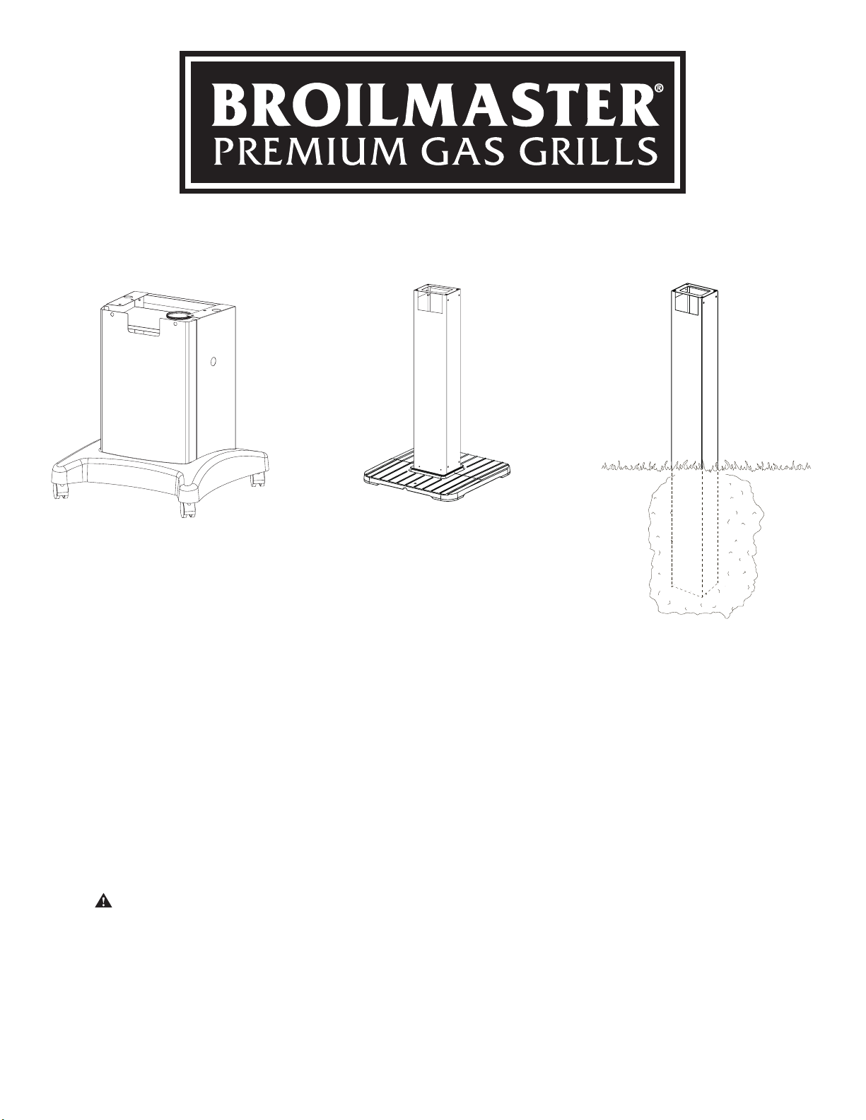
MODELS MODELS
PCB1-2
DCB1-2
BL26P-1
SS26P-1
MODELS
BL48G-1
SS48G-1
vErify thAt All pArtS liStEd on thE ExplodEd viEw of thiS mAnuAl hAvE bEEn inCludEd in
thiS CArton bEforE bEginning inStAllAtion.
CAution: uSE CAution whEn hAndling pArtS, AS thEy mAy ContAin ShArp EdgES.
work glovES ArE rECommEndEd to prEvEnt injury.
Keep This Owner’s Manual FOr FuTure reFerence.
EmpirE Comfort SyStEmS, inC • 918 frEEburg AvE. • bEllEvillE, il 62220
B101586-1-1011 Page 1
Page 2

tAblE of ContEntS
CongrAtulAtionS!
You have chosen the nest grill for your outdoor cooking pleasure. Please take time to read this entire manual before assembling your Broilmaster® Grill accessory.
Important Information ......................................................................................................... 4
PCB1-2, DCB1-2 Installation Instructions ........................................................................ 5-9
Cart Exploded View & Parts List ...................................................................................... 6
Cart Assembly ............................................................................................................ 7 - 9
BL26P-1, SS26-1 Patio Base Installation Instructions .............................................. 10 - 13
Patio Base Exploded View & Parts List .......................................................................... 11
Patio Base Installation ............................................................................................ 12 - 13
BL48G-1, SS48G-1 In-Ground Post Installation Instructions .................................... 14 - 17
In-Ground Post Exploded View & Parts List .................................................................. 15
In-Ground Post Assembly ....................................................................................... 16 - 17
Appliance Service History ................................................................................................. 18
Template for Mounting Holes ............................................................................................ 19
B101586-1-1011Page 2
Page 3

thiS gAS ACCESSory iS dESignEd for outdoor uSE only
IMPORTANT:
This manual should be read thoroughly by the person installing the grill mounting and all persons who will
use and maintain the grill mounting. The installer should be sure the manual is left in the possession of the
user. The user should retain this manual for future reference when using or cleaning the grill mounting and to
properly identify any repair parts that may be required.
WARNING:
Reference this manual for proper installation and maintenance instructions. Improper installation, adjustment,
alteration, service or maintenance can cause personal injury or property damage. For assistance or additional
information consult a qualied installer, service agency or the gas supplier.
CAUTION:
The grill and its individual shutoff valve must be disconnected from the gas supply piping system during any pressure
testing of that system at test pressures in excess of 1/2 PSIG.
CAUTION:
The grill must be isolated from the gas supply piping system by closing its individual manual shutoff valve during any
pressure testing of the gas supply piping system at test pressures equal to or less than 1/2 PSIG.
CAUTION:
Parts may have sharp edges. Wear leather work gloves and handle parts carefully during the unpacking,
assembly and the installation.
WARNING:
Do not supply LP gas to a grill designed for natural gas nor natural gas to a grill designed for LP gas.
NOTICE:
Assemble grill mount before assembling grill.
B101586-1-1011 Page 3
Page 4

iMpOrTanT inFOrMaTiOn
Grill Location
Broilmaster® Gas Grills are designed for outdoor use
ONLY.
These mounting accessories are designed for use with
Broilmaster® gas grills and must not be used with any
other grill or for any other purpose.
Never install or operate your grill in any building, garage,
or other enclosed area.
For your safety, the grill should not be installed or operated under any combustible materials, such as carports,
covered porches, awnings, or overhangs.
Never install or use your grill in or on any recreational
vehicle or boat.
CAution: thE inStAllAtion And opErAtion of thiS
grill At ClEArAnCES lESS thAn SpECifiEd bElow mAy lEAd
to thE poSSibility of firE, propErty dAmAgE, or pErSonAl
injury.
A minimum clearance of eighteen (18”) inches is re-
quired from the back of the grill to any combustible
material.
gas Types
Never use liquid propane gas with a grill designed for
natural gas, or natural gas with a grill designed for liquid
propane gas. The type of gas required for your grill is
dened on its product identication label. Questions
regarding different types of gases should be directed
to your gas supplier.
Cleaning
The exterior of your cart or post may be cleaned with
hot water and mild detergent as needed.
Touch-up paint is available through your Broilmaster
dealer.
Stainless steel surfaces may be cleaned with a sprayon stainless steel cleaner available at most hardware
stores.
Important: Do not use harsh or abrasive cleaners! Your
cart or post has a highly polished surface and may be
easily scratched.
®
Periodic Inspection and
Examples of combustible materials are patio furniture,
fences, or the wall of your home.
The area surrounding the grill should be clear to ensure
proper ventilation. Do not obstruct the ow of combustion and ventilation air in any way. The ventilation
openings on the propane cylinder enclosure must also
remain free and clear of debris.
wArning: do not inStAll or opErAtE A gAS grill
whErE gASolinE or othEr flAmmAblE mAtEriAlS ArE uSEd
or StorEd. fAilurE to Comply with thiS wArning Could
rESult in ExploSion or firE CAuSing propErty dAmAgE or
pErSonAl injury.
Maintenance
Periodic inspections and maintenance are essential. All
Broilmaster® Gas Grill products or mechanical devices
eventually begin to wear due to environment, contaminants, corrosion or aging. Inspect all components at
least twice per year and replace any that show wear.
If any parts are damaged or missing, you may order parts
from your local Broilmaster® dealer. Please refer to the
Parts Diagram and Parts List section of this manual for
more detailed information.
B101586-1-1011Page 4
Page 5
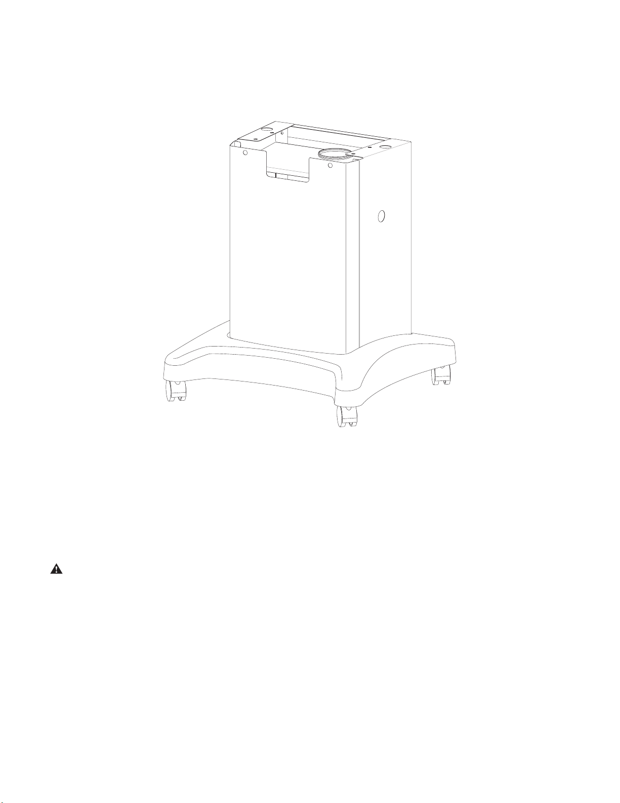
pCb1-2, dCb1-2
insTallaTiOn insTrucTiOns
vErify thAt All pArtS liStEd on thE ExplodEd viEw of thiS mAnuAl hAvE bEEn inCludEd in
thiS CArton bEforE bEginning inStAllAtion.
CAution: uSE CAution whEn hAndling pArtS, AS thEy mAy ContAin ShArp EdgES. work
glovES ArE rECommEndEd to prEvEnt injury.
rEmovE protECtivE CoAting And vErify thAt All pArtS liStEd on thE ExplodEd viEw of thiS mAnuAl hAvE
bEEn inCludEd bEforE bEginning ASSEmbly.
toolS rEquirEd: phillipS SCrEw drivEr (An ElECtriC SCrEw drivEr or drill iS
rECommEndEd to EASE inStAllAtion.)
B101586-1-1011 Page 5
Page 6
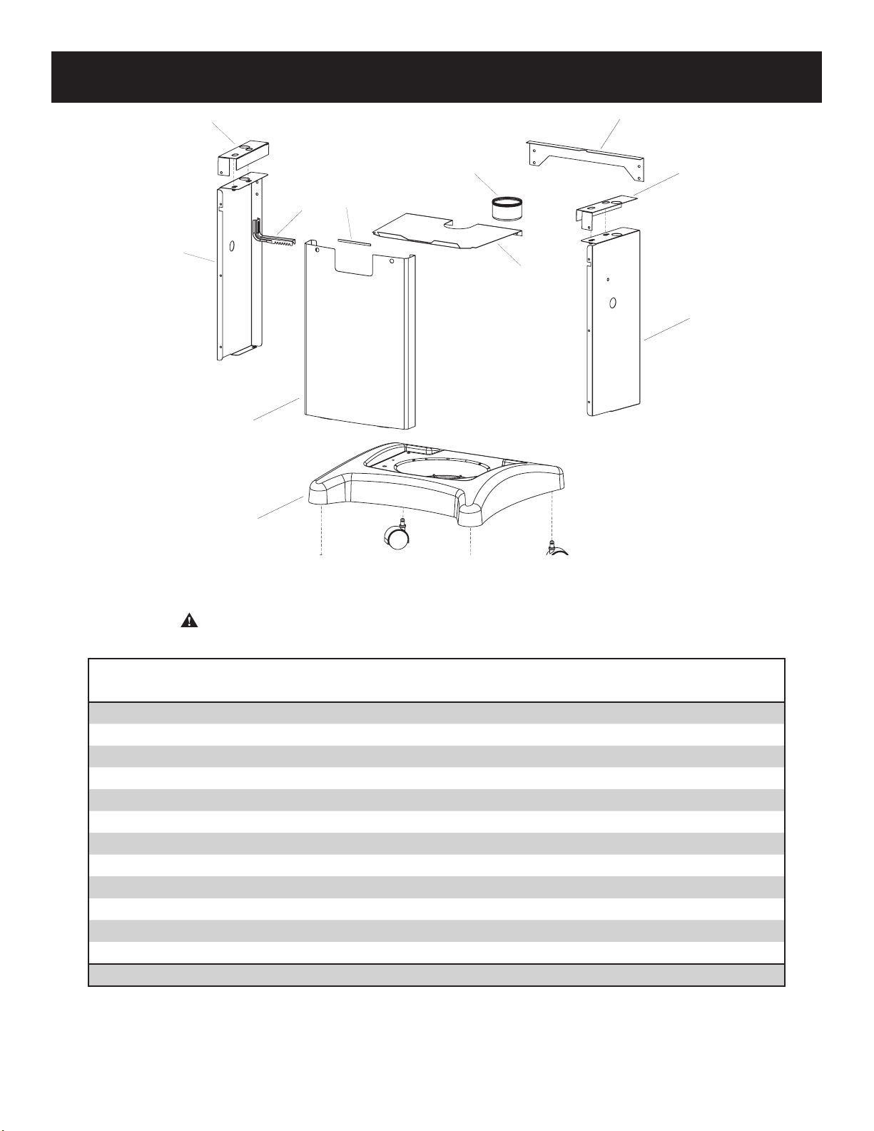
CArt ExplodEd viEw & pArtS liSt
11
6
13
10
3
5
1
7
4
12
2
Remove protective coating from stainless steel parts starting at pop rivets and verify that all parts listed in the
exploded view on this page have been included before beginning this
installation.
Caution: Use caution when handling parts, as they may contain sharp edges.
Work gloves are recommended to prevent injury.
INDEX
NO.
1 B101585 B101584 B101465 Front Panel
2 B101466 B101463 B101560 Left Side Panel Assembly
3 B101467 B101464 B101561 Right Side Panel Assembly
4 B101583 B101582 B101582 Rear Brace
5 B101633 B101633 B101633 Cart shield stainless steel
6 B101473 B101473 B101473 Grease Cup
7 B101414 B101414 B101415 Plastic Base
8 B101416 B101416 B101416 Caster with Brake
9 B101417 B101417 B101417 Caster without Brake
10 B064791 B064791 B064791 Cylinder Retainer
11 B101565 B101565 B101495 Base Support Bracket - Right
12 B101495 B101495 B101565 Base Support Bracket - Left
13 B101635 B101635 B101635
PCB1 DCB1 H3PK1
PART NO.
DESCRIPTION
Channel, Edge Protector
All repair part orders should be placed through your local Broilmaster® dealer. To locate a dealer in your area, visit
www.broilmaster.com. To ensure prompt and accurate service, please provide the following information when placing a repair part order: Model Number, Part Name, Part Number, and Quantity of parts needed.
B101586-1-1011Page 6
Page 7

CArt ASSEmbly
Caution: Be careful when handling parts, as they may
contain sharp edges. Work gloves are recommended to prevent
injury. Remove protective plastic covering.
1. For Stationary Cart Assembly: Use the template on page
23 to locate and pre-drill the three screw holes into wood or
concrete for the cart base. If applicable, drill the 1 1/2” gas line
access hole. DO NOT secure base with the screws at this time.
For Mobile Cart Assembly: Flip plastic base and insert casters
by inserting the pin provided with the casters in the proper hole.
It is recommended that the two casters with brakes should be
in the front of the base. See Figure 1.
3. Align the holes on the front and side panel assemblies and
secure with six #10-24 x 1/2” Phillips screws and 10-24 Keps
Nuts provided (3 on each side). Do not tighten these screws
until all are installed. Use black screws for black carts and
stainless steel screws for stainless steel carts. See Figures 2
and 3.
Figure 1
2. Place the base support brackets on the side panels. Slide the
short anges on the brackets between the top and side anges
of the side panels. See Figure 2.
Figure 3
4. Secure the completed assembly to the base with four
1/4-20 x 3/4” Phillips Truss screws. See Figure 4. Note: Plastic
base comes with factory installed threaded inserts. Install all
four screws before tightening.
Figure 2
B101586-1-1011 Page 7
Figure 4
Page 8

CArt ASSEmbly
5. Attach Rear Brace to the Left and Right Side Assemblies with
two 1/4-20 x 3/4” Phillips Truss Head screws and 1/4-20 Hex
nuts. See Figure 5. Important: Make sure the brace goes in
the cutout of the support bracket.
Figure 5
6. Insert busing in the front panel on the right for P and H series
and on the left for R and T series grills. See Figure 6.
Figure 6
Note: Bushing is used to protect the ignitor wires from
rubbing on the front panel when they are in place.
Note: Ignitor wires must go through the bushing before grill
head is fully installed.
7. Secure the grill head to the cart using four 1/4-20 x 3/4” Hex
Head Bolts and 1/4 x 5/8 Flat Washers. See Figure 7. Note:
To ease assembly, you may wish to install the ignitor as
shown in your Broilmaster® grill manual before attaching
the grill to the cart.
Figure 7
8. Attach the Heat Shield to the Left and Right side assemblies
with two 1/4-20 x 3/4 Phillips Truss Head screws and 1/4-20
Hex nuts. Make sure shield is resting on the cutout provided
in the side panels before tightening the screws and nuts. See
Figures 8 and 9. Note: Grill head removed for clarity.
Figure 8
Figure 9
B101586-1-1011Page 8
Page 9

CArt ASSEmbly
9. For Grill Heads other than R3 Series, continue on to Step 10.
For R3 Series Grill Heads: Press in the two sides of the
Control Housing (provided with Grill Head) and t it into the
opening under the grill head as shown in Figure 10. Grill
Assembly will look like Figure 11.
Note: It may be easier to insert one side of the control housing
rst, and then press in the other side using the cart as a brace
for the inserted side.
10. Mount the tank retainer to the cart by using 1/4-20 x 1 1/4 Phillips Truss Head screw and 1/4-20 wing nut.
Figure 12
10. Install Grease Cup by sliding it in the cutout provided in the
shield.
Figure 10
Figure 11
Figure 13
11. For Stationary Cart Assembly: Slide grill assembly into position over holes drilled in Step 1. Secure with three screws (not
supplied). If applicable, route the gas line through the hole and
attach to the grill.
B101586-1-1011 Page 9
Page 10

bl26p-1, SS26-1 pAtio bASE
insTallaTiOn insTrucTiOns
wArning: thiS pAtio bASE iS not dESignEd for uSE with An lp gAS CylindEr.
wArning: SEE your grill ownEr'S mAnuAl for propEr loCAtion, minimum ClEArAnCES,
And othEr importAnt SAfEty informAtion bEforE proCEEding with inStAllAtion of thiS
paTiO pOsT.
vErify thAt All pArtS liStEd on thE ExplodEd viEw of thiS mAnuAl hAvE bEEn inCludEd
in thiS CArton bEforE bEginning inStAllAtion.
CAution: uSE CAution whEn hAndling pArtS, AS thEy mAy ContAin ShArp EdgES. work
glovES ArE rECommEndEd to prEvEnt injury.
B101586-1-1011Page 10
Page 11

pAtio poSt ExplodEd viEw & pArtS liSt
3.08
2.63
8
Remove protective coating from stainless steel parts starting at pop rivets and verify that all parts listed in the
exploded view on this page have been included before beginning this
installation.
Caution: Use caution when handling parts, as they may contain sharp edges.
Work gloves are recommended to prevent injury.
INDEX NO.
1 B101411 B101408 Post
2 B101454 B101454 Upper Bracket Assembly
3 B100526 B100526 Grease Cup
4 B076519 B076519 Flex Line
5a B743095 B743095 Grease Retainer Top Assembly
5b B743098 B743098 Grease Retainer Bottom Assembly
6 B101579 B101579 Lower Bracket Assembly
7 B074604 B074604 Cast Base
8* B101596 B101596 Post Cover Plate - Black
8* B101597 B101597 Post Cover Plate - Stainless Steel
Not Shown B101569 R2737 #10 x 1/2 Hex Head Screw
* Post Cover Plate is used only when installing R3 Series grill head onto post.
All repair part orders should be placed through your local Broilmaster dealer. To locate a dealer in your area, contact Broilmaster
Customer Service • www.broilmaster.com To ensure prompt and accurate service, please provide the following information
when placing a repair part order: Model Number, Part Name, Part Number, and Quantity of parts needed.
SS26P BL26P
PART NO.
DESCRIPTION
B101586-1-1011 Page 11
Page 12

pAtio bASE inStAllAtion
NOTICE: Assemble post before assembling grill.
The SS26P and BL26P Patio Bases are only for use with Broilmaster
Gas Grills. Before proceeding with installation read your Owner’s
Manual for the proper location and minimum clearances to combustible materials for your grill and in-ground post.
Verify that all parts listed in the exploded view of this product have
been included before beginning this installation.
Recommended Tools:
• Drill/Driver
• Two adjustable wrenches or a socket set
• A medium Phillips screwdriver
• Pipe thread sealer or Teon tape (for gas connections)
• Soapy water solution (to test for leaks)
1. Attach lower bracket assembly to post with eight #10-1/2”
screws. See Figure 1.
NOTE: The large rectangular cut out is located at the front of the
post near the top.
2. Fasten the bottom of the post to the cast base using 1/4 lock
washers, and 1/4-20 hex bolts. See Figure 2. Anchor the
cast iron patio base to your patio using the two holes provided in the base. (Hardware not included)
Note: Make sure that the large rectangular cut out is facing in
the direction that you want your grill to face.
Figure 2
3. Insert the stainless steel ex tube assembly into the post. The
inlet side of the gas tubing may protrude from the bottom of
the patio base or through the large circular hole in the back of
the square post. See Figure 3. Note: Do not attempt to cut or
alter the ex tube in any way.
Figure 1
Figure 3
4. For Grill Heads other than R3 Series, continue on to Step 5.
For R3 Series Grill Heads: Bend the tabs on the Post Cover
Plate to 90° as shown in Figure 4.
Note: If using the stainless steel Post Cover Plate, bend the
tabs so they face away from the protective lm. Remove the
protective lm after bending the tabs.
PROTECTIVE
FILM SIDE
COVER PLATE
Figure 4
B101586-1-1011Page 12
Page 13

pAtio bASE inStAllAtion
5. For R3 Series Grill Heads: Slide the Post Cover Plate onto the
front of the post. Slide the Upper Bracket onto the post. Secure
the Post Cover Plate and Upper Bracket to the top of the square
post using four #10 – ½ screws. See Figure 5.
For Grill Heads other than R3 Series: Slide the Upper
Bracket into the post. Secure the Upper bracket to the top of
the square post using four #10 – ½ screws. See Figure 5.
Figure 5
6. Position the grill head onto the post and fasten with ¼-20 x ¾
Hex Head and lock washers. See Figure 6.
WARNING: DO NOT SUPPLY LP GAS TO A GRILL DESIGNED FOR NATURAL GAS OR NATURAL GAS TO A GRILL
DESIGNED FOR LP GAS.
Gas leak tests should be completed as directed in the grill
owner’s manual.
8. Attach the grease cup bracket assembly to the bottom of the
grill casting and fasten with #10-24 x 3/4” bolt, 9/32 ID x 5/8 OD
washer, and #10-24 wing nut.
Note: Grill head comes assembled with the bottom casting. To
ease assembly remove grill top.
Loosen the wing nut and move the slide up or down to accept
the grease cup. Be sure to trap the rim of the cup as shown on
page 10. Use only the supplied grease cup or noncombustible
containers for the grease cup (aluminum or tin cans).
DO NOT use combustible containers such as Styrofoam or
paper cups.
Figure 7
9. Continue assembly as directed by the Owner’s Manual packaged with the grill head.
Figure 6
7. Arrange with your local gas company or licensed contractor to
have a gas supply line connected to the inlet of the stainless
steel ex tube assembly. The gas supply must have a shutoff
valve that is close to the post in case of emergency and must
be shutoff when the grill is not in use.
Test for gas leaks as directed by the grill’s Owners Manual.
The grill and its individual shutoff valves must be disconnected
from the gas supply piping system during any pressure testing
of that system at test pressures in excess of 1/2 PSIG. The grill
must be isolated from the gas supply piping system by closing
its individual manual shutoff valves during any pressure testing
of the gas supply piping system at test pressures equal to or
less than 1/2 PSIG.
B101586-1-1011 Page 13
Page 14

bl48g-1, SS48g-1 in-ground poSt
insTallaTiOn insTrucTiOns
wArning: thiS in-ground poSt iS not dESignEd for uSE with An lp gAS CylindEr.
wArning: SEE your grill ownEr’S mAnuAl for propEr loCAtion, minimum ClEArAnCES, And
othEr importAnt SAfEty informAtion bEforE proCEEding with inStAllAtion of thiS in-ground
pOsT.
vErify thAt All pArtS liStEd on thE ExplodEd viEw of thiS mAnuAl hAvE bEEn inCludEd in thiS
CArton bEforE bEginning inStAllAtion.
CAution: uSE CAution whEn hAndling pArtS, AS thEy mAy ContAin ShArp EdgES. work glovES
ArE rECommEndEd to prEvEnt injury.
B101586-1-1011Page 14
Page 15

in-ground poSt ExplodEd viEw & pArtS liSt
3.08
8
Remove pRotective coating fRom stainless steel paRts staRting at pop Rivets and veRify that all paRts listed in the exploded
view on this page have been included befoRe beginning this installation.
cauTiOn: use caution when handling paRts, as they may contain shaRp edges.
woRk gloves aRe Recommended to pRevent injuRy.
INDEX NO. PART NUMBER DESCRIPTION
SS48G BL48G
1 B101413 B101409 Post
2 B101454 B101454 Upper Bracket Assembly
3 B100526 B100526 Grease Cup
4 B076519 B076519 Flex Line
5 B101569 R2737 #10 x 1/2 Hex Head Screw
6 B101490 B101546 Post Access Door
7 B100545 B100545 Grease Cup Bracket Assembly
8* B101596 B101596 Post Cover Plate - Black
8* B101597 B101597 Post Cover Plate - Stainless Steel
* Post Cover Plate is used only when installing R3 Series grill head onto post.
All repair part orders should be placed through your local Broilmaster dealer. To locate a dealer in your area, visit www.
broilmaster.com. To ensure prompt and accurate service, please provide the following information when placing a repair
part order: Model Number, Part Name, Part Number, and Quantity of parts needed.
B101586-1-1011 Page 15
Page 16

in-ground poSt ASSEmbly
NOTICE: Assemble patio base before assembling grill.
TheSS48G and BL48G In-Ground Posts are only for use with
Broilmaster Gas Grills. Before proceeding with installation read
your Owner’s Manual for the proper location and minimum clearances to combustible materials for your grill and in-ground post.
Verify that all parts listed in the exploded view of this product have
been included before beginning this installation.
Recommended Tools:
• Drill/Driver
• Two adjustable wrenches or a socket set
• A medium Phillips screwdriver
• Pipe thread sealer or Teon tape (for gas connections)
• Soapy water solution (to test for leaks)
1. Dig a posthole approximately 12” in diameter and 24” in depth
at the desired grill location.
Note: “Normal Installation” height is achieved when the
top of the 48” post is 25 1/4” above ground. This height
provides a cooking surface height of approximately
34 1/2” above ground when grids are placed in the high level.
The gas supply line should be trenched at least 10 inches
below the surface of the ground to prevent damage from dig-
ging. CAUTION: The gas supply line must be regulated
(In the case of Natural gas that means connected after your
gas meter and regulator) and that you have an easily accessible shut-off valve.
At the access door connect a 3/8” are coupling (not supplied
by Empire) to the gas supply line and stainless steel tubing.
Position the tubing in the top notch of the post. Bend the ex
tube at the top end to match the Feed Line of the grill valve.
See Figure 1.
Note: Use pipe thread sealant or Teon tape at the threads
of each connection being careful to not allow any of these
materials into the are seat. Test for gas leaks as directed by
the grill’s Owners Manual
Note: Do not attempt to cut or alter the stainless steel ex
tube assembly in any way.
Note: For R Series Grills, a Cover Plate will be supplied, so
the Flex Line will have to go through the hole on the cover
plate before mounting the Grill bottom.
Carefully lower the in-ground post into the hole using the following guidelines:
• The rectangular cut-out is located near the TOP of the
post and should be above ground after installation. See
Figure 1.
• The rectangular cut-out must face in the SAME direction
as the front of the grill.
• Hole depth and post measurements should be checked
to ensure desired height.
Note: Make any adjustments at this time.
Figure 1
Prepare concrete or a standard pre-mix according to the man-
ufacturer’s package directions. Position the 48” post in the
center of the hole. A level should be used when aligning the
post to achieve precise vertical alignment. Hold the post in
place while pouring the concrete mixture into the hole around
the post.
2. For Grill Heads other than R3 Series, continue on to
Step 3.
For R3 Series Grill Heads: Bend the tabs on the Post Cover
Plate to 90° as shown in Figure 2.
Note: If using the stainless steel Post Cover Plate, bend the
tabs so they face away from the protective lm. Remove the
protective lm after bending the tabs.
PROTECTIVE
FILM SIDE
COVER PLATE
Figure 2
B101586-1-1011Page 16
Page 17

in-ground poSt ASSEmbly
3. For R3 Series Grill Heads: Slide the Post Cover Plate onto the
front of the post. Slide the Upper Bracket onto the post. Secure
the Post Cover Plate and Upper Bracket to the top of the square
post using four #10 – ½ screws. See Figure 3.
For Grill Heads other than R3 Series: Slide the Upper
Bracket into the post. Secure the Upper bracket to the top of
the square post using four #10 – ½ screws. See Figure 3.
Figure 3
4. Place the grill bottom on top of the post and secure the grill bottom
to the post by placing four ¼-20 x ¾ Hex head screw in the threaded inserts that are in the upper bracket. See Figure 3.
Note: Grill top comes assembled with to the bottom. For ease
of assembly, remove grill top.
WARNING: DO NOT SUPPLY LP GAS TO A GRILL DESIGNED FOR NATURAL GAS OR NATURAL GAS TO A
GRILL DESIGNED FOR LP GAS.
Gas leak tests should be completed as directed in the grill
Owner’s Manual.
Completely ll remaining hole with soil.
Figure 5
6. Attach the grease cup bracket assembly to the bottom of the
grill casting and fasten with #10-24 x 3/4” bolt, 9/32 ID x 5/8
OD washer, and #10-24 wing nut. See Figure 6.
Use only the supplied grease cup or noncombustible containers for the grease cup (aluminum or tin cans). DO NOT use
combustible containers such as paper or Styrofoam cups.
Figure 6
7. Continue assembly as directed by the Owner’s Manual pack-
Figure 4
5. Arrange with your local gas company or licensed contractor to
have a gas supply line connected to the inlet of the stainless
steel ex tube assembly. The gas supply must have a shutoff
valve that is close to the post in case of emergency and must
be shutoff when the grill is not in use. See Figure 5
The grill and its individual shutoff valves must be disconnected
from the gas supply piping system during any pressure testing
of that system at test pressures in excess of 1/2 PSIG. The
grill must be isolated from the gas supply piping system by
closing its individual manual shutoff valves during any pressure testing of the gas supply piping system at test pressures
equal to or less than 1/2 PSIG.
B101586-1-1011 Page 17
aged with the grill head.
Page 18

APPLIANCE SERVICE HISTORY
Date Dealer Name Service Technician Name Service Performed/Notes
B101586-1-1011Page 18
Page 19

B101586-1-1011 Page 19
Page 20

BROILMASTER
A Division of Empire Comfort Systems, Inc.
918 Freeburg Ave.
Belleville, Illinois 62220
Phone: 1-800-851-3153
FAX: 1-800-443-8648
visit ouR web site at www.broilmaster.com
®
reTain Owner’s Manual FOr FuTure reFerence.
B101586-1-1011Page 20
 Loading...