

Broaster VF3iXP, VF-2XP Installation & Operation Manual
“An American Tradition Since 1954!”
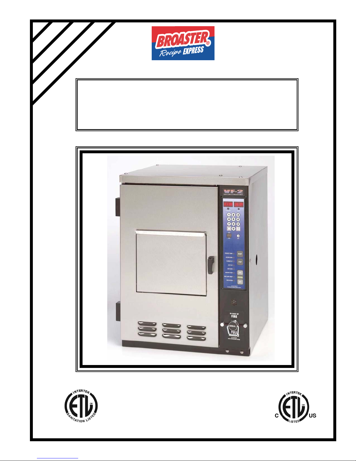
MODEL VF-2XP & VF3iXP
BROASTER
®
VENTLESS FRYER
INSTALLATION & OPERATION MANUAL
Be sure ALL installers read, understand, and have access to this manual at all times.
Broaster®,,Broasted®, Broaster Chicken®, Broaster Foods®, and Broasterie® are registered trademarks.
Usage is available only to licensed operators with written authorization from The Broaster Company.
2855 Cranston Road, Beloit, WI 53511-3991
Design Certified By:
Printed in U.S.A.
ETL (US & CAN), ETL Sanitation
The Broaster Company
608/365-0193 www.broaster.com
16887 4/09
Copyright 2006 The Broaster Company

FOR YOUR SAFETY
Do not use or store gasoline or other flammable vapors
or liquids in the vicinity of this or any other appliance.
WARNING: Improper installation, adjustments, alteration, service or maintenance can
cause property damage, injury or death. Read the installation, operating and maintenance instructions thoroughly before installing or servicing this equipment.
For the sake of safety and clarity, the following words used in this manual are defined as follows:
DANGER: Indicates an imminently hazardous situation which, if not avoided, could result
in serious injury or death.
WARNING: Indicates a potentially hazardous situation which, if not avoided, could result
in serious injury or death.
CAUTION: Indicates a potentially hazardous situation which, if not avoided, could result in
minor injury, property damage or both.
All adjustments and repairs shall be made
by an authorized Broaster Company representative.
If there is a power failure, turn power switch
OFF. DO NOT attempt to operate unit during a power failure.
WARNING: Failure to read and
understand this manual completely
could result in serious injury or death. Be
sure ALL operators read, understand and
have access to this manual at all times.
WARNING: Rags or papers containing
cooking oil can catch fire if exposed to
heat. Laundering will not remove the oil. Dispose of all oil-soiled papers and rags in a trash
container that is in a ventilated area away from
all cooking equipment or other heat sources
such as direct sunlight.
DANGER: DO NOT clean this fryer with
a water jet. Use of this cleaning method
could result in serious injury or death.
Manual #16887 5/08


NEW OWNER OR RELOCATION NOTIFICATION
If you are a new owner of a used unit or
®
have relocated your Broaster
VF-2 or VF3i
Fryer, please take a minute to fill out one of
the cards below. It is NOT a warranty registration.
PLEASE PRINT: 2
Business Name:
This card enables The Broaster Company to
better serve you and keep you informed of
changes in equipment, condiments, or service bulletins.
Address:
City: State: Zip Code:
Owner’s Name:
County:
Phone:
Model:
Serial Number:
PLEASE PRINT: 1
Business Name:
Address:
City: State: Zip Code:
Owner’s Name:
County:
Phone:
Model:
Serial Number:
Manual #16887 5/08

The Broaster Company
2855 Cranston Road
Beloit, WI 53511
The Broaster Company
2855 Cranston Road
Beloit, WI 53511
Manual #16887 5/08

TABLE OF CONTENTS
1 - OWNER RESPONSIBILITY ..........................................................................................1 - 1
2 - INSTALLATION .............................................................................................................2 - 1
LOCATION..................................................................................................................2 - 1
CLEARANCES............................................................................................................2 - 1
GENERAL REQUIREMENTS.....................................................................................2 - 1
UNPACKAGING..........................................................................................................2 - 2
FIRE SUPPRESSION ACTIVATION...........................................................................2 - 2
ELECTRICAL CHARACTERISTICS...........................................................................2 - 3
ELECTRICAL CONNECTIONS ..................................................................................2 - 3
ELECTRICAL AMPERGE RATING.............................................................................2 - 3
WIRING DIAGRAM
VF-2 EXPORT & CE...........................................................................................2 - 4
VF3i EXPORT & CE............................................................................................2 - 5
INITIAL START-UP......................................................................................................2 - 6
2 - GETTING TO KNOW YOUR BROASTER® VF-2 or VF-3i FRYER..............................2 - 1
4 - PRE-COOKING PREPARATION...................................................................................4 - 1
START-UP...................................................................................................................4 - 1
COOKING OIL ............................................................................................................4 - 1
FOOD AND CONDIMENTS........................................................................................4 - 1
5 - CONTROL PANEL ........................................................................................................5 - 1
DUAL DISPLAY FAMILIARIZATION ...........................................................................5 - 1
OPERATIONAL LOCKOUT ........................................................................................5 - 2
CONTROLLER BASIC PROGRAMMING...................................................................5 - 2
Normal Operating Mode......................................................................................5 - 2
Preset Cook Mode ..............................................................................................5 - 3
Programming Procedure.....................................................................................5 - 3
Manual #16887 5/08

6 - FIRE SUPPRESSION SYSTEMS..................................................................................6 - 1
GENERAL DESCRIPTION .........................................................................................6 - 1
AUTOMATIC OPERATION .........................................................................................6 - 1
MANUAL OPERATION ...............................................................................................6 - 1
INSPECTION & MAINTENANCE................................................................................6 - 1
Gaining Access...................................................................................................6 - 1
Monthly Inspection..............................................................................................6 - 2
Semi-Annually.....................................................................................................6 - 2
T welve Year.........................................................................................................6 - 3
SEMI-ANNUAL INSPECTION & MAINTENANCE LOG .............................................6 - 3
7 - VENTILATION SYSTEM................................................................................................7 - 1
8 - PRODUCT PREPARATION AND COOKING................................................................8 - 1
COOKING...................................................................................................................8 - 1
9 - COOKING OIL CARE....................................................................................................9 - 1
10 - CLEANING ................................................................................................................10 - 1
COOKING UTENSILS...............................................................................................10 - 1
HAND CLEANING METHOD....................................................................................10 - 1
DISHWASHER METHOD.........................................................................................10 - 1
CLEANER NEUTRALIZATION..................................................................................10 - 1
UNIT SURFACES .....................................................................................................10 - 1
DISHWASHER SAFE COMPONENTS.....................................................................10 - 1
MINIMUM PREVENTATIVE MAINTENANCE REQUIR EMENTS.............................10 - 1
11 - NIGHTLY SHUTDOWN/SEASON SHUTDOWN .......................................................11 - 1
NIGHTLY SHUTDOWN.............................................................................................11 - 1
SEASON SHUTDOWN.............................................................................................11 - 1
12 - TROUBLESHOOTING...............................................................................................12 - 1
ELECTRICAL TIPS...................................................................................................12 - 1
INDICATOR LIGHTS.................................................................................................12 - 2
SOLID STATE CONTROLLER TIPS.........................................................................12 - 3
FROZEN IQF PRODUCT..........................................................................................12 - 3
Manual #16887 5/08 rev 4/09

1 - OWNERS RESPONSIBILITY
It is the owner’s responsibility to:
• Insure the Broaster® VF-2, VF-3i Fryer
is properly maintained.
• Allow only properly trained personnel to
operate, clean and maintain a Broaster®
VF-2, VF-3i Fryer.
• Schedule and maintain documentation
that the appropriate inspection and
maintenance of the Fire Suppression
system has been completed.
• Retain this manual for future reference.
• Insure main power supply is discon-
nected before the unit is serviced.
• Ensure that all safety devices are intact
and the operation manual is included
with the unit when you sell, trade, dispose of, or give away your Broaster®
VF-2, VF-3i Fryer.
If you need replacement manuals, contact
an authorized Broaster Company representative or The Broaster Company at 608/365-
0193.
The Customer Service Department at The
Broaster Company should be contacted at
the time of sale or disposal of the Broaster®
VF-2, VF-3i Fryer so records may be
updated.
• Insure a proper surface is provided for
the Broaster® VF-2, VF-3i Fryer to sit
on.
• Keep the louvres in both the front and
the rear of unit free from obstructions.
• Ensure that access is not obstructed to
the fire suppression system. Fire suppression status can be monitored by
viewing through the right side panel
access hole.
Manual #16887 5/08
1 - 1


2 - INSTALLATION
As you progress through the set-up of your VF-2, VF-3i fryer, refer to Chapter 4, GETTING TO
KNOW YOUR BROASTER® VF-2, VF-3i FRYER for part descriptions and locations.
LOCATION
For convenience and speed, location of the
unit should be given careful consideration.
If possible, locate the unit so the flow of
cooked product is in a straight line from storage, in and out of the unit and to the customer. Landing tables should be provided
on at least one side of the unit.
• A flat, level, stable surface capable of
supporting an additional weight of 200
lbs is required for the safe operation of
this unit.
• To avoid splashing of hot liquid, unit
must be restrained to prevent tipping.
• Provision must be made to eliminate
movement of the unit which might cause
strain on electrical connections.
• DO NOT install unit where traffic areas
are on either side or in back of unit.
• DO NOT install unit where the louvres in
either the front or the rear are blocked or
void of ventilation.
• DO NOT install unit where access to fire
suppression system is blocked. Fire
suppression activation is located on front
panel. Fire suppression status can be
monitored by viewing through the right
side panel access hole.
CLEARANCES
Recommended clearances are:
Left Side: 0”
Rear: 2”
Right Side: 0” Note: You must be able to
access the right side panel periodically for
inspection and service.
GENERAL REQUIREMENTS
• When installing or servicing the unit,
always check the dataplates, located
toward the rear of the unit. This will
make certain proper parts are used and
the correct service rendered. DO NOT
apply a voltage to this unit other than
that shown on the dataplate. If in doubt,
consult your local power company.
• A remote circuit breaker or fuse should
be installed in main power supply
located in a path of exit and clearly identified.
• The VF-2 is 19 in. wide by 24.25 in. tall
by 20.12 in. deep.
• The VF-3i is 23 in. wide by 27 in. tall by
24.5 in. deep.
• Installation must conform to local codes
or in their absence with National codes
UL 197, UL 197SB, NFPA 70 for electrical, NFPA 96 for ventilation, NFPA 17A
for Wet Chemical Extinguishing Systems, also Canadian Electrical CSA
22.2.
• Unit to be sealed to countertop (ie. silicone) or elevate on legs with optional
platform.
2 - 1
Manual #16887 5/08
UNPACKING
FIRE SUPPRESSION ACTIVATION
1. Remove external cardboard packaging.
CAUTION: DO NOT cut cardboard
with utility knife. Damage to unit could
result.
2. Open Access Door by lifting Access
Door Latch and turning counter-clockwise. Remove Cooking Pot cardboard
retainer.
3. Remove Cooking Basket, Basket Platform, and cardboard/styrofoam seperator from Cooking Pot.
4. Remove tape from Air and Grease Filters.
5. Raise the Element by placing Element
Arm above Element Retainer and
remove the Cooking Pot.
6. Follow cleaning instructions as outlined
in CLEANING, Section 10 of this manual.
DANGER: DO NOT apply power to
unit until completing this procedure.
Failure to do so would leave the unit without
Fire Suppression capability.
7. To gain access to the Fire Suppression
system remove Electrical Control
Access Panel. Remove retaining
screw, slide the panel up, then pull the
bottom toward the outside of the unit.
8. Inside the cooking area, verify that
there is tension on the cable connected
to the Fusible Link.
CAUTION: If there is no tension on
the link, removing the Fire Suppression Arming Pin will activate the Fire Suppression System. Contact authorized
Broaster Company representative.
9. Verify the Fire Extinguisher gauge registers in the green.
DANGER: If the gauge does not regi-
ester green, DO NOT operate the unit.
The Fire Suppression System will not function to a satisfactory level. Contact authorized Broaster Company representative.
10. Inside the Electrical Control area,
11. Remove Fire Suppression Arming Pin
12. Replace the Electrical Control Access
2 - 2
Manual #16887 5/08
locate strap securing Fire Suppression
Arming Pin. Cut and remove the strap.
and let hang from connected chain.
The Fire Suppression System is now
active.
Panel and retaining screw.

ELECTRICAL CHARACTERISTICS
ELECTRICAL CONNECTIONS
The unit is available for 120/240 VAC or
120/208 VAC applied voltage, 30 amp,
60Hz, 1 phase electrical connection in the
USA and Canada. (4 wire with neutral and
ground)
• When installed, the unit is to be field
wired and must be electrically grounded
in accordance with local codes, or in the
absence of local codes, with the National
Electrical Code, ANSI/NFPA 70, or the
Canadian Electrical Code, CSA C22.2,
as applicable.
ELECTRICAL AMPERAGE RATING
Applied voltage should match dataplate
listed voltage.
The electrical schematics can be found on
pages 4 thru 7 of this section.
Input
Voltage
120/240 23 23 --- --- --- --120/208 27 27 --- --- --- ---
220 --- --- 21 28 --- --230 --- --- --- --- 22 29
VF2
Domestic
VF3i
Domestic
VF2
Export
VF3i
Export
VF2
CE
VF3i
CE
2 - 3
Manual #16887 5/08
 Loading...