

Broaster V4 Installation Manual
INSTALLATION, OPERATION AND
MAINTENANCE MANUAL FOR
ELECTRIC INDUSTRIAL
PROCESS WATER HEATER
ELECTRIC HEATER COMPANY
BASE MODEL “ V ”
ASME ANSI/NSF5
2009 Edition Rev. -

HUBBELL
ELECTRIC HEATER COMPANY
45 SEYMOUR STREET
P.O. BOX 288
STRATFORD, CT 06615
PHONE: (203) 378-2659
FAX: (203) 378-3593
INTERNET: http://www.hubbellheaters.com
-- IMPORTANT --
Always reference the full model number and serial number when calling the factory.
WARNING / CAUTION
1. Tank is to be completely filled with water and all air is to be vented before energizing.
2. Due to the rigors of transportation, all connections should be checked for tightness before
heater is placed in operation.
3. Safety relief valve must be installed in tapping provided.
4. The refractory material used in heating elements may absorb some moisture during
transit, periods of storage, or when subjected to a humid environment. This moisture
absorption results in a cold insulation resistance of less than twenty (20) m egohm s. If this
heater has been subjected to the above condition, each heating element must be checked
for insulation resistance before energizing. Contact the factory for a replacement element.
5. KEEP AWAY FROM LIVE ELECTRICAL CIRCUITS.
Do not perform any maintenance, make any adjustments, or replace any components
inside the control panel with the high voltage power supply turned on. Under certain
circumstances, dangerous potentials may exist even when the power supply is off. To
avoid casualties, always turn the power supply safety switch to off, turn the charge or
ground the circuit before performing any maintenance or adjustment procedure.
6. The unit is designed to operate at pressure not more than 150 psi.
7. Generalized instructions and procedures cannot anticipate all situations. For this reason,
only qualified installers should perform the installations. A qualified installer is a person
who has licensed training and a working knowledge of the applicable codes, tools,
equipment, and methods necessary for safe installation of an electric resistance water
heater. If questions regarding installation arise, check your local plumbing and electrical
inspectors for proper procedures and codes. If you cannot obtain the required
information, contact the company.
8. Water Quality Requirements – Recommended water hardness is 4 to 6 grains of
hardness per gallon (GPG). Water hardness above 6 GPG should be treated by a water
conditioner (water softener or in-line treatment). Water hardness below 4 GPG also
requires treatment to reduce potential corrosion. Excessive GPG will result in higher
operating and maintenance costs and will reduce product longevity. Chlorides must
not exceed 50 parts per million (ppm). Excessive chlorides will result in metallic
corrosion and will reduce product longevity. Water treatment has been shown to
reduce costs associated with de-liming the heater as well as reducing metallic
corrosion. Product failure caused by these conditions is not covered under warranty.
See warranty for complete details.
2

TABLE OF CONTENTS
SECTION TITLE PAGE No.
I GENERAL DESCRIPTION AND CONSTRUCTION 4
II INSTALLATION AND START-UP 9
III SCHEDULED MAINTENANCE AND OPERATION 24
IV TROUBLESHOOTING 26
V SERVICING AND REPLACEMENT OF PARTS 32
VI SERVICE PARTS LIST 35
VII TORQUE VALUES 37
VIII WARRANTY INFORMATION 38
3

SECTION I - GENERAL DESCRIPTION AND CONSTRUCTION
GENERAL DESCRIPTION
This book describes a packaged electric water heater designed for use in an industrial or
commercial application. The complete assembly consists of the storage tank, immersion electric
heating element(s), electronic control module, safety relief valve, magnetic contactor(s), and
any other required electrical operating control. Optional equipment may be supplied with your
unit. Please consult the product drawing supplied with the unit for details specific to your
assembly. The unit is factory assembled, insulated, jacketed, wired, tested, and ready for
electrical and plumbing service connections.
CAPACITY
Storage
Model
V32.9 3 2.9 20 15 12 10 V161 16 1 6 5 4 3
V35.7 3 5.7 39 29 23 19 V161.5 16 1.5 10 7 6 5
V39.9 3 9.9 68 51 41 34 V162 16 2 13 10 8 6
V310.4 3 10.4 71 53 43 36 V163 16 3 20 15 12 10
V311.4 3 11.4 78 58 47 39 V164 16 4 27 20 16 13
V411 4 11.4 78 58 47 39 V166 16 6 41 30 24 20
V415 4 15 103 77 62 51 V167 16 7 47 35 28 23
V427 4 27 185 138 111 92 V169 16 9 61 46 36 30
V61.5 6 1.5 10 8 6 5 V1613 16 13.5 92 69 55 46
V610 6 10.5 72 54 43 36 V1640 16 40.5 276 207 166 138
V612 6 12 82 62 49 41 V1645 16 45 307 230 184 153
V613 6 13.5 92 69 55 46 V1654 16 54 369 276 221 184
V615 6 15 103 77 62 51 V1658 16 58.5 399 299 239 199
V618 6 18 123 92 74 62 V1664 16 64 437 328 262 218
V624 6 24 164 123 98 82 V1666 16 66 451 338 270 225
V627 6 27 185 138 111 92 V1668 16 68 464 348 278 232
V630 6 30 205 154 123 103 V1679 16 79 539 404 323 269
V636 6 36 246 185 148 123 V1681 16 81 553 415 332 276
V639 6 39 267 200 160 133 V1685 16 85 580 435 348 290
V640 6 40.5 277 208 166 138 V1686 16 86 587 440 352 293
V645 6 45 308 231 185 154 V1688 16 88 601 451 360 300
V654 6 54 369 277 221 185 V1690 16 90 615 461 369 307
V658 6 58.5 400 300 240 200
Capacity
(gallons)
V61617543 V1612 16 12 82 61 49 41
V62 6 2 14 10 8 7 V1615 16 15 102 76 61 51
V63 6 3 21 15 12 10 V1618 16 18 123 92 73 61
V64 6 4 27 21 16 14 V1624 16 24 164 123 98 82
V65 6 5 34 26 21 17 V1627 16 27 184 138 110 92
V66 6 6 41 31 25 21 V1630 16 30 205 153 123 102
V67 6 7 48 36 29 24 V1636 16 36 246 184 147 123
V69 6 9 62 46 37 31 V1639 16 39 266 199 159 133
kW
60°F
Rise
(GPH)
80°F
Rise
(GPH)
100°F
Rise
(GPH)
120°F
Rise
(GPH)
Model
Storage
Capacity
(gallons)
kW
60°F
Rise
(GPH)
80°F
Rise
(GPH)
100°F
Rise
(GPH)
If the required temperature rise is not listed above, the following formula may be used to
determine the maximum flow rate:
Flow Rate (GPH) = kW * 410 / Temperature Rise (°F)
Required kW = Temperature Rise (°F) * Flow Rate (GPH) * 0.00244
120°F
Rise
(GPH)
4
5
6

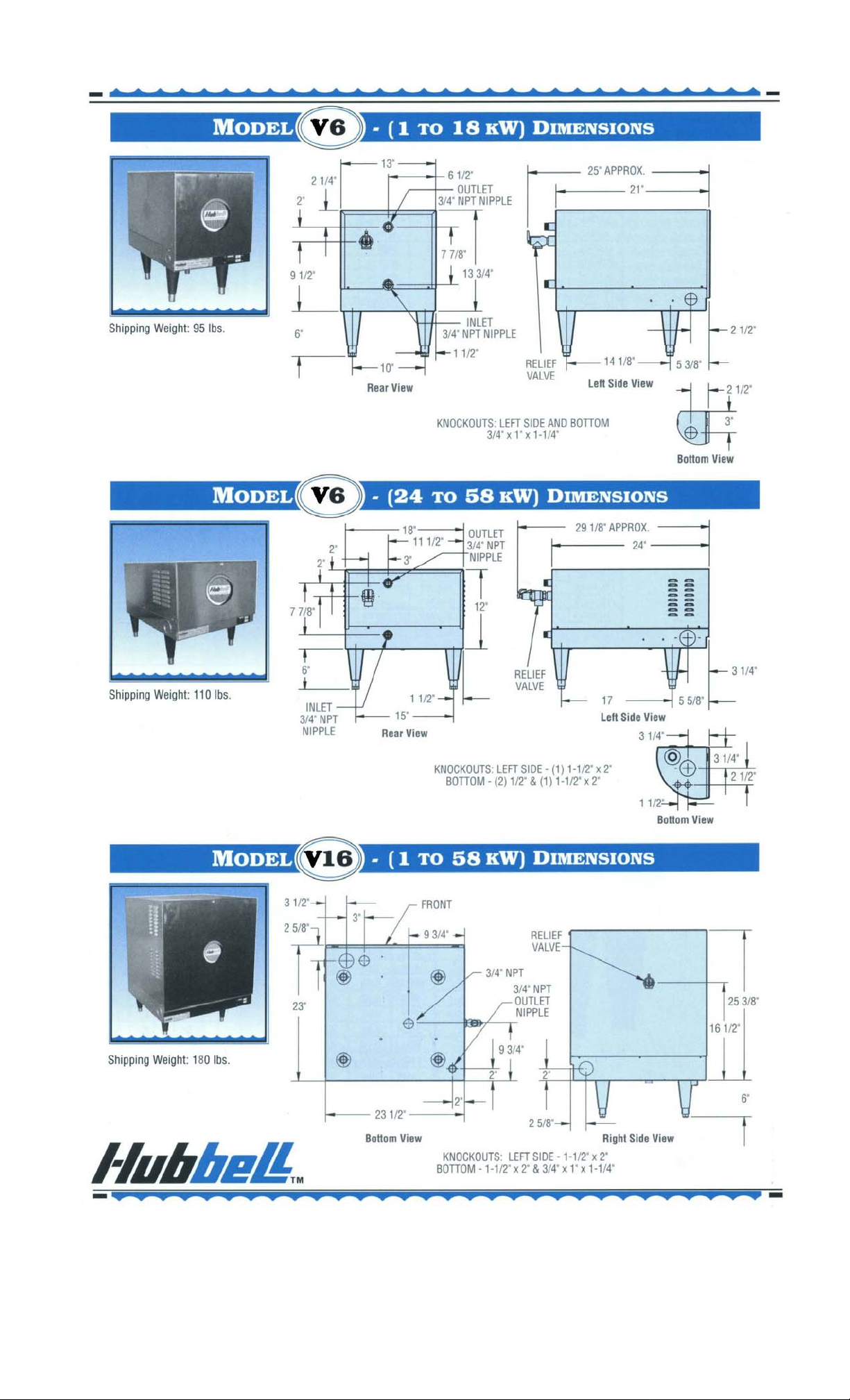
CONSTRUCTION
TANK
The storage tank is designed, manufactured, and stamped in accordance with ASME section
VIII Division 1. The tank is constructed of type 304L stainless steel and fabricated by all
welded construction and is designed for a maximum allowable working pressure of 150 psi
(225 psi TP).
TANK CONNECTIONS
The heater is supplied with separate connections for the cold/warm inlet and the hot water
outlet. Water entering the cold water inlet and leaving through the hot water outlet is evenly
circulated by means of a diffuser within the tank. A ¾-inch FNPT connection is provided for
mounting a combination safety temperature and pressure relief valve. An overflow line should
be utilized from the relief valve outlet to a floor drain. See drawing for locations and sizes.
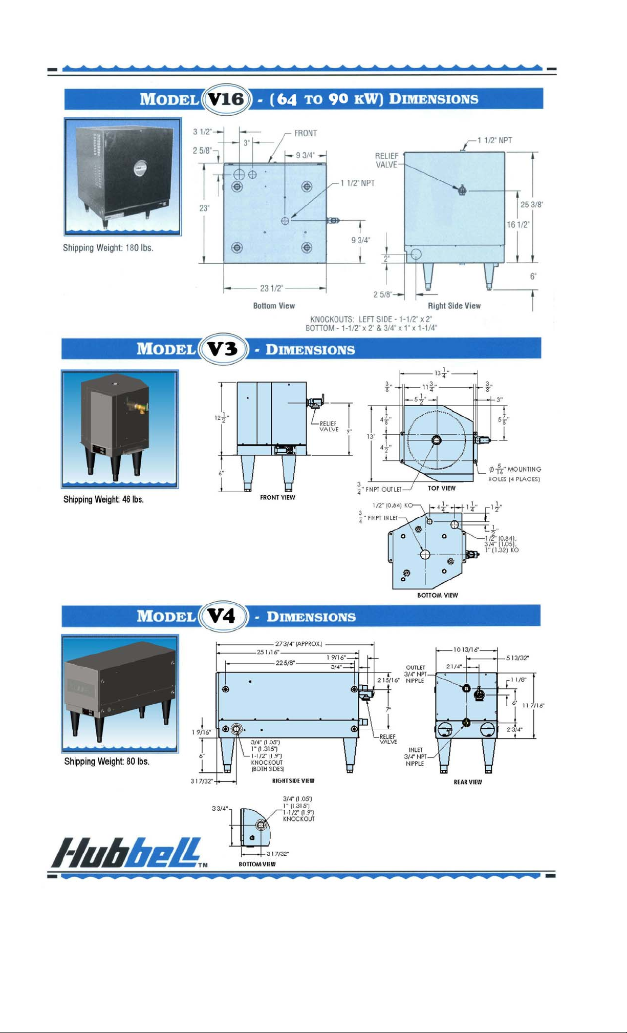
HEATING ELEMENT
The water heater is supplied with an electric
immersion heating element assembly(s), composed
of copper sheathed elements that are fitted into a
brass 1½-12UNF screw plug with 1-7/8” hex. Each
assembly is threaded into the tank and sealed with an o-ring gasket. See drawing for voltage and
power ratings. Note that the V3 model element is a 1” NPS thread with a 1 ½” hex.
MAGNETIC CONTACTOR
The definite purpose magnetic contactor(s) is a heavy-duty resistive
load type. The contactor supplies power to the heating element(s)
based on the resistive load (non-inductive) of the heater only when
the relay on the control board is closed, thereby pulling in the
contacts until the desired temperature is reached. At this point, the
contacts will drop out, which in turn disconnects power from the
elements. Units with two contactors will turn on and off in stages.
CONTROL BOARD AND DISPLAY
The control board supplies all the
necessary function for heater operation.
These include control temperature, hilimit cut-out, low water detection, and
leak detection.
LOW VOLTAGE CONTROL TRANSFORMER
A control circuit transformer is supplied with all models rated
greater than 240-volts. This component is used to step down the
primary power supply (600, 480, 440, 415, 380, or 277) to 208/240volts for safety when working with control circuits.
POWER CIRCUIT BREAKERS
When required by code, a magnetic power circuit breaker is
supplied for circuit overload protection. The circuit breaker can
be reset in the event of a current overload.
OUTER SHELL, INSULATION, AND SUPPORTS
The tank is encapsulated in high efficiency foam insulation meeting the requirements for UL 94
HF-1 rating. The protective shell is constructed of type 304 brushed stainless steel. NSF
approved adjustable plastic legs are provided for support.
DIELECTRIC UNIONS
Dielectric unions are provided for the inlet and outlet nipples to isolate stray
ground currents to reduce the possibility of galvanic corrosion.
7
OPTIONAL EQUIPMENT
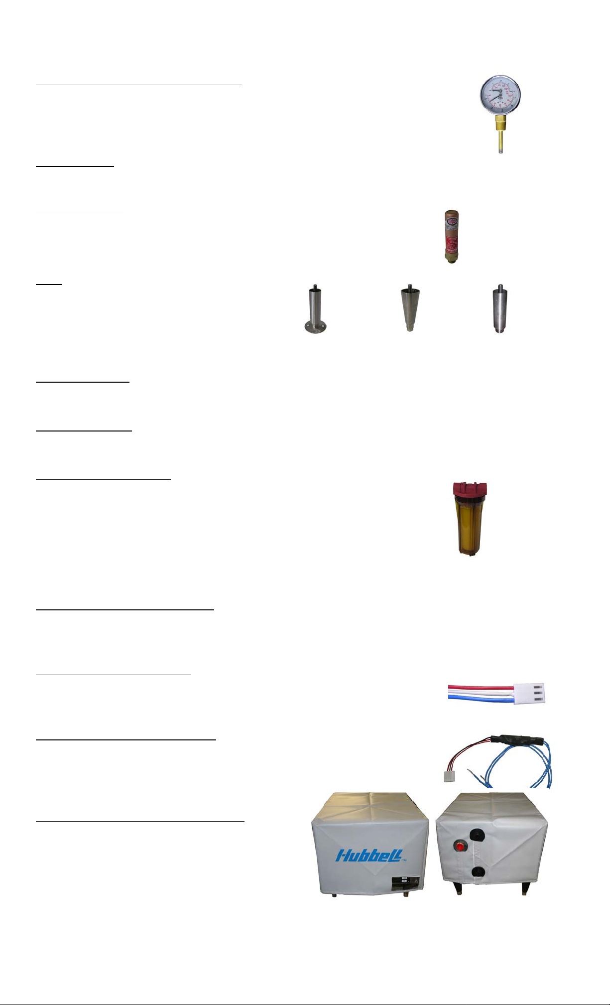
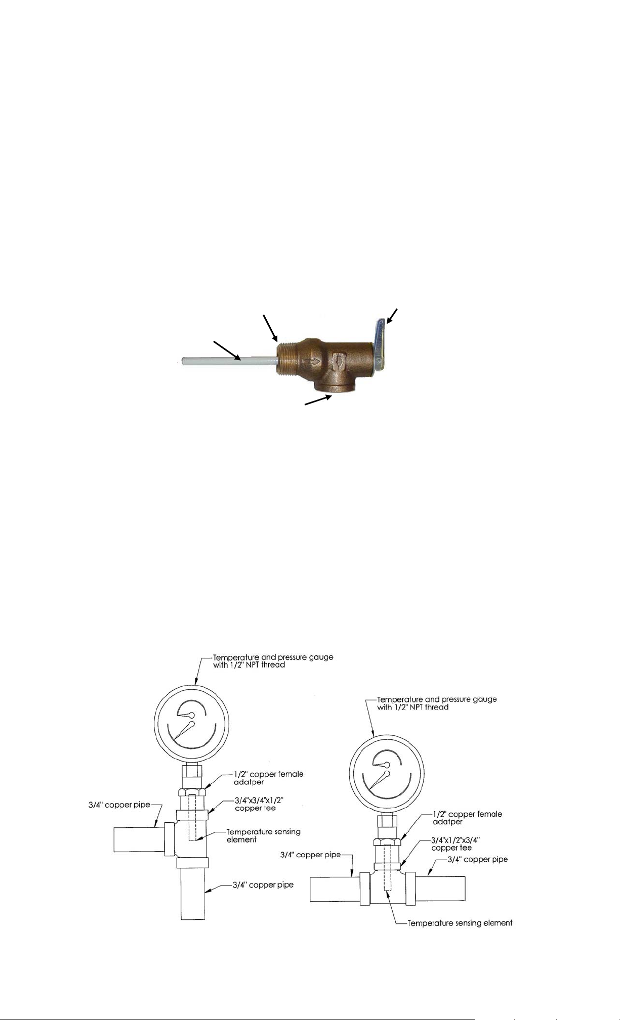
Dial Temperature and Pressure Gauge
A combination temperature (30°-240° F / 0°-120°C) and pressure (0–200 psi
/ 0-1400 kPa) gauge with 3-inch dial is supplied with the unit for in-line
installation (shipped loose). The connection is ½” NPT with a 2” long
sensing probe.
Slide Brackets
Available for the V6 Model only, these brackets allow for mounting the water heater under a
counter. See slide bracket diagram on page 9 for details.
Shock Absorber
The optional shock absorber can be installed between the heater
and the process to reduce the harmful pressures resulting from
quick closing solenoid valves.
Legs
In lieu of the standard black plastic legs,
optional adjustable legs are available in
stainless steel, die-cast nickel plated, and
floor mount stainless steel. All optional
legs are adjustable height type. Floor Mount Nickel Plated Stainless Steel
Security Package
A tamper resistant package is available. All external screws are spader type requiring a spader
wrench for removal.
Alternate Voltage
Other voltages are available, including 277V single-phase, and 380V, 415V, and 440V threephase. Consult the factory for details.
Water Treatment System
The optional water treatment system provides superior mineral
scale prevention and corrosion control by feeding a special blend
of scale control compounds into the cold water stream before the
heater. The in-line system includes a clear cartridge housing to
allow an operator to view an operator to view the cartridge and
determine when it needs replacement without the need to open the
system.
XB1 Low Temperature Interlock
An optional in-line control board with separate manual setpoint (range: 165°F – 194°F)
monitors the temperature of the water through the P65 probe and will trip a SPDT relay for
customers’ remote applications.
Remote Alarm Plug Adapter
An optional plug adapter is available to provide a remote fault alarm
signal through the J4 connector on the control board. See page 12 for
installation details.
24-Volt Heater Interlock Adapter
An optional plug adapter is available to interlock the heater via a 24-volt
signal through the J1 connector on the control board. See page 13 for
installation details. (Only available with r23 or
later software).
Protective Shrouds (V6 and V16 only)
An optional durable protective plastic shroud is
available to prevent damage to the heater due to
water intrusion. The cover fits snugly over the
entire heater and can be easily removed for
cleaning and service.
8
SECTION II – INSTALLATION AND START-UP
WARNING / CAUTION
• DO NOT TURN ON THE ELECTRIC POWER SUPPLY to this equipment until
heater is completely filled with water and all air has been released. If the heater is
NOT filled with water when the power is turned on, the heating elements will burn
out.
• For protection against excessive pressures and temperatures, local codes require the
installation of a temperature-and-pressure (T&P) relief valve certified by a nationally
recognized laboratory that maintains periodic inspection of production of listed
equipment of materials, as meeting the requirements for Relief Valves and Automatic
Gas Shutoff for Hot Water Supply Systems. ANSI Z21.22-1971. THE CUSTOMER
IS RESPONSIBLE TO PROTECT PROPERTY AND PERSONNEL FROM HARM
WHEN THE VALVE FUNCTIONS.
• All water heaters have a risk of leakage at some unpredictable time. IT IS THE
CUSTOMER'S RESPONSIBILITY TO PROVIDE A CATCH PAN OR OTHER
ADEQUATE MEANS, SO THAT THE RESULTANT FLOW OF WATER WILL
NOT DAMAGE FURNISHINGS OR PROPERTY.
• Installation or service of this unit requires ability equal to that of a licensed tradesman
in the field.
• The installation must conform to these instructions and any local authority having
jurisdiction. Grounding and electrical wiring connected to the unit must also conform
to the latest version of the National Electric Code NFPA-70.
WATER HEATER PLACEMENT
1. Place the heater on a solid, level foundation in a clean, dry location.
2. The water heater should be protected from freezing and waterlines insulated to reduce
energy and water waste.
3. Leave a minimum of 18” clearance for element withdrawal and control access.
4. Do not install in an area where flammable liquids or combustible vapors are present.
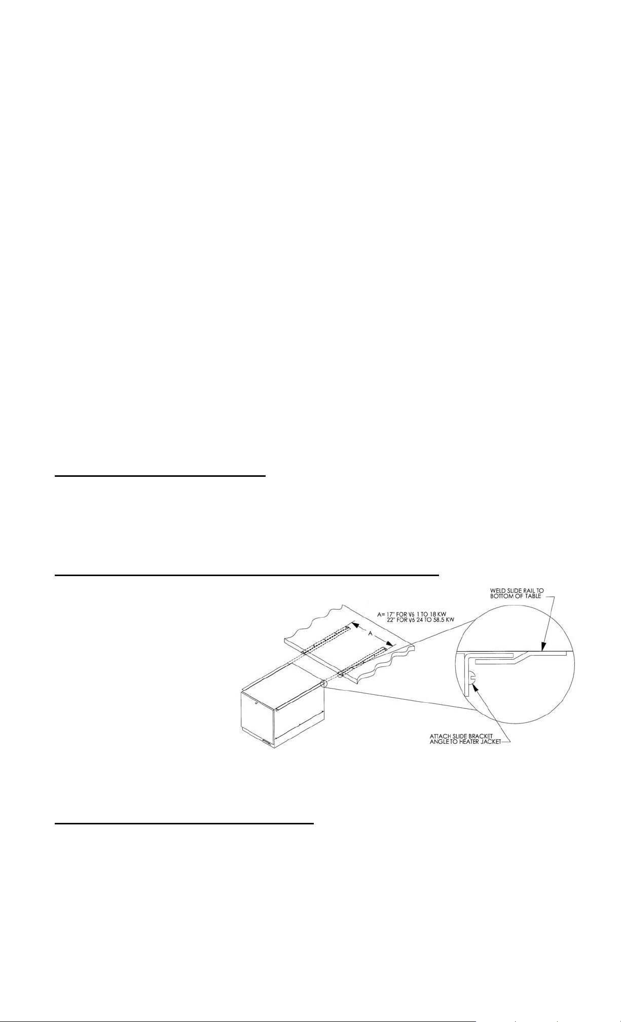
SLIDE BRACKETS FOR HANGING SUPPORT MOUNTING
1. Weld slide rails to
bottom of table.
Spacing should be 17”
for V6 models up to
18kW and 22” for V6
models 24 to 58.5kW.
V16 models are not
designed for use with
slide brackets.
2. Attach slide bracket
angles to heater with #8
sheet metal screws. It will be necessary to drill 1/8” holes into heater jacket for screw
pilot holes.
3. Slide heater onto slide rails under table.
PIPING INSTALLATION – See Diagrams
NOTES:
• No check valve may be installed in the supply line to the heater.
• All shut-off valves must be gate or ball valves – not globe valves.
• To minimize heat loss and maximize efficiency, hot water piping should be insulated.
• Teflon tape should be used on all NPT threaded pipe connections.
1. Install the factory supplied dielectric unions on the inlet and outlet piping.
9
2. Connect the cold water inlet and hot water outlet to the appropriate connections as
shown; refer to the specifications for location and sizes.
IMPORTANT (applies to V6 Models only) – Do not turn the entering cold water or
exiting hot water nipples from their factory installed positions. The internal diffusers
are aligned at the factory and turning the nipple will change the diffuser position and
affect performance. Hubbell recommends that the inlet and outlet pipes are insulated
to prevent excessive heat loss.
IMPORTANT (applies to V6 Models only) – Do not apply heat directly to the
entering cold water or exiting hot water nipples. If sweat connections are to be used,
sweat tubing to the adapter before threading the adapter to the nipple on the heater.
Any heat applied to the heater nipple will damage the internal plastic diffuser and
affect performance.
3. Install the combination temperature and pressure safety relief valve in the tapping
provided. Note that this is required by law for safety considerations.
Install into provided tapping Manual Release Lever
Temperature Probe
Outlet to floor drain
Temperature and Pressure Relief Valve
4. Install a relief valve overflow pipe to a nearby floor drain.
NOTE: Relief valve discharge piping limitations:
a. Termination to be plain end (no threads)
b. Maximum 30-feet
c. Maximum four (4) elbows
d. No reduction in line size
e. No valve of any type to be installed between the relief valve and tank or in the
drain line
f. Termination to be 6-inches above the drain
5. Install the dial temperature and pressure gauge (if supplied) in the inlet and/or outlet
line. The temperature sensing element must be in the hot water stream and the gauge
must be mounted upright.
10

FILLING THE HEATER
1. Open the valve to the cold water inlet and allow the heater and piping system to
completely fill, as indicated by a steady flow of water through process outlet.
NOTE: Flush the tank at full flow for 10 minutes prior to putting into service.
ELECTRICAL INSTALLATION
1. Enter the base through the factory cut KO’s with properly sized feeder leads, See
Wiring Chart. Single-phase installations require two (2) leads. All Hubbell 3-phase
heaters are intended for use with a 3-wire delta system plus ground. No neutral is
required. For a 4-wire plus ground system, install 3 legs of power plus the ground and
terminate the neutral leg.
2. Install these power leads into the box lugs on the power distribution block or magnetic
contactor, as required.
3. Connect incoming ground wire to ground lug supplied.
4. Check for proper grounding. Check for AC millivolts (mV) between the ground
connection at the heater and the inlet piping past the dielectric union (on the building
side, not the heater side). There should be zero potential/millivolts (mV). If not zero,
then the piping should be re-grounded.
5. All other electrical connections are made at the factory; therefore, no other electrical
connections are necessary.
6. Check all connections, including factory connections, for tightness.
OPTIONAL XB1 LOW TEMPERATURE INTERLOCK
1. If desired, the XB1 can be used as an alarm relay or a temperature interlock at a
setpoint other than the water temperature setpoint on the heater.
2. If the XB1 is not factory installed, mount the XB1 to the control panel, plug the P65
probe into the XB1, and plug the XB1 into the T1000 control board.
3. To set the XB1 setpoint, turn the potentiometer clockwise for a higher setpoint and
counter-clockwise for a lower setpoint. The range is adjustable between 150°F and
180°F.
4. Make connections as required to the relay terminal block. When the temperature drops
below the XB1 setpoint the relay is open between Normally Open (NO) and Common
(C) and the LED will flash green. When the temperature is above the XB1 setpoint the
relay is closed between NO and C and the LED will be solid green. Use NO and C for
low temperature interlock or high temperature alarm. Use Normally Closed (NC) and C
for low temperature alarm. A red LED indicates an error.
LED
Relay
Note: Rating (resistive):
Terminal Block
Max.: 5A @ 120VAC
5A @ 24VDC
Temperature Adjustment Potentiometer
FOR REMOTE ON/OFF
CONTROL
Remote Relay by Customer
Wiring by
Customer
To remotely control the On /
Off operation of the heater, it
is recommended that a DPST
switch or relay (by others) be
used to break both power legs
(white and black wires)
Wiring from Contactor,
Power Distribution Block,
or Transformer
1
2
3
4
connected to the top two
terminals of the J5 connector
Controller J5 Connector
on the control board. See
diagram at right.
Use a NC (Normally Closed)
Red Wire to
Contactor #2
Yellow Wire to
Contactor #1
11
relay to turn the heater ON when energizing the relay coil or to turn the heater OFF when de-
ying
energizing the relay coil.
Use a NO (Normally Open) relay to turn the heater OFF when energizing the relay coil or to
turn the heater ON when de-energizing the relay coil.
OPTIONAL REMOTE ALARM CONTACTS
1. If desired, the control board can be wired to a remote alarm to indicate a reset fault
condition. These fault conditions include over-temperature, no probe, and low water
(when the configuration is set to manual reset).
2. This alarm can be wired to the J4 connector on the control board as shown below. To
facilitate this installation, an optional adapter, Hubbell P/N PLUG ADAPTER J4, can
be purchased to provide wire connections.
J4 Connector
Note: Rating (resistive)
Max. Switching Power:
60W, 62.5VA
Max. Switching Voltage:
220VDC, 250VAC
Max. Switching Current: 2A
Max. Carr
Current: 3A
PLUG ADAPTER J4
(NO)
(NC)
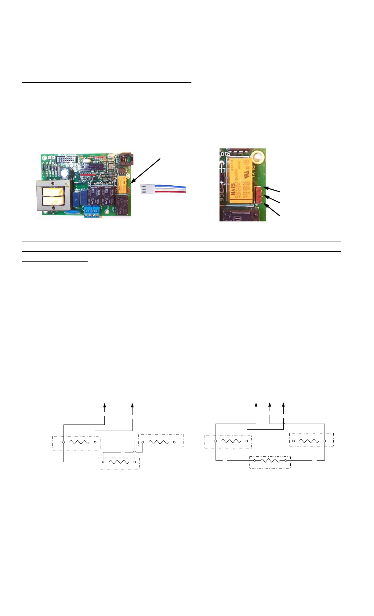
OPTIONAL FIELD CONVERSION FROM SINGLE TO THREE PHASE OR THREE
TO SINGLE PHASE (V6 and V16 models in 6, 7, and 9 kW and 208 and 240 volts and
V411 models only)
1. For V6 and V16 models:
a. Find the appropriate diagram for the unit to be converted in the following chart
titled “Wiring Chart”.
b. Re-wire the unit according to the diagram.
NOTE: The wire to be used for internal wiring must conform to SEW-2 or
PTFE (200°C) and must match the wire size currently in use. Contact the
factory for assistance if required.
c. Contact the factory for correct labels. The factory will need the serial number
for proper identification.
2. For V411 models:
a. Re-wire the unit to desired configuration as indicated below.
Single-Phase 3-Phase
TO CONTACTOR
TO CONTACTOR
12
P1
T1
P4
WIRING DIAGRAM SHOWN IS FOR MODEL V411RS (SINGLE PHASE).
TO FIELD CONVERT TO 3-PHASE, REMOVE WIRE P2 AND RECONNECT
IT BETWEEN TERMINALS T6 AND THE CONTACTOR AND REMOVE WIRE
P5 AND RECONNECT IT BETWEEN TERMINALS T2 AND T5.
T2
T3 T4
P3
T5
P5
P2
P6
P1 P2
T6
T1
P4
WIRING DIAGRAM SHOWN IS FOR MODEL V411R (3-PHASE).
TO FIELD CONVERT TO SINGLE PHASE, REMOVE WIRE P2 AND
RECONNECT IT BETWEEN TERMINALS T3 AND T5 AND REMOVE
WIRE P5 AND RECONNECT IT BETWEEN TERMINALS T2 AND T4.
T2
T3 T4
P3
P5
T5
T6
P6
 Loading...