

Broaster 1800, 1600, 1800EXP, 1800GHXP, 1800GH Service Manual
...
1600 1800
SERVICE MANUAL
BROASTER® 1600 AND 1800
PRESSURE FRYER w/SMART TOUCH CONTROL
Be sure ALL installers read, understand, and have access to this manual at all times.
Genuine Broaster Chicken®, Broasted®, Broaster Chicken®, Broaster Foods®. and Broasterie® are registered
trademarks. Usage is available only to licensed operators with written authorization from the Broaster Company.
2855 Cranston Road, Beloit, WI 53511-3991
Design Certified By:
1600: CSA, NSF and UL
1800: CSA (AGA & CGA), NSF and UL
Broaster Company
608/365-0193 broaster.com
Manual #17270 10/13 Rev 9/16
© 2013 Broaster Company
Printed In U.S.A.


All adjustments and repairs shall be made
FOR YOUR SAFETY
Do not use or store gasoline or other flammable vapors
or liquids in the vicinity of this or any other appliance.
Improper installation, adjustments, alteration, service or maintenance can cause
property damage, injury or death. Read the installation, operating and maintenance instructions thoroughly before installing or servicing this equipment.
For the sake of safety and clarity, the following words used in this manual are defined as follows:
Indicates an imminently hazardous situation which, if not avoided, could
result in serious injury or death.
Indicates a potentially hazardous situation which, if not avoided, could
result in serious injury or death.
Indicates a potentially hazardous situation which, if not avoided, could
result in minor injury, property damage or both.
by an authorized Broaster Company representative.
when the cook/filter switch is moved to
If at any time the POWER
ON light does not turn off
the OFF position, disconnect the power
If there is a power failure, turn cook/filter
switch OFF. On the Model 2400GH, also
slide switch on gas valve OFF. DO NOT
to the fryer and contact your local
Broaster Company representative for
service immediately.
attempt to operate unit during a power failure.
DO NOT operate unit
without filter pan and filter
Failure to read and
understand this manual
completely could result in serious injury
pan cover in its proper position. Filter
pan cover must be wiped clean after
each filtering cycle.
or death. Be sure ALL operators read,
understand and have access to this
manual at all times.
Rags or paper containing
ports on bottom of cover are clear of any
oil or grease buildup.
Make sure Pressure Relief
Valve and Pressure Gauge
cooking oil can catch fire
if exposed to heat. Laundering will not
remove the oil. Dispose of all oil-soiled
papers and rags in a trash container that
is in a ventilated area away from all
cooking equipment or other heat
sources such as direct sunlight.
cont’d on next page
W-1
broaster.com Manual #17270 10/13 Rev: 10/15

1800GH:
Post, in prominent locations, instructions to
be followed in the event that the user smells
gas. This information can be obtained from
your local gas supplier.
Make sure a restraining
device is used that
complies with the Standard for
Commercial Gas Ranges, ANSI Z83.11/
CSA 1.8 to guard against transmission of
strain to the gas connectors.
Failure to restrain the
fryer could allow it to
move, causing hot shortening to spill
out, or a possible break in the gas line
causing an explosive condition.
broaster.com Manual #17270 10/13 Rev: 10/15
W-2

TABLE OF CONTENTS
1 - WARNING SIGNS AND LABELS
1600 ........................................................................................................................ 1 - 1
1800 ........................................................................................................................ 1 - 2
Pictures .................................................................................................................... 1 - 3
2 - ELECTRIC POWER SUPPLY
WIRING DIAGRAMS
Electrical Connection - Single and Three Phase Power Connection ................. 2 - 1
DOMESTIC 1600/1800E ST ............................................................................... 2 - 2
EXPORT 1600XP ST .......................................................................................... 2 - 3
EXPORT 1800EXP ST ........................................................................................ 2 - 4
DOMESTIC 1800GH ST...................................................................................... 2 - 5
EXPORT 1800GHXP ST ..................................................................................... 2 - 6
3 - SMART TOUCH CONTROL PANEL
FAMILIARIZATION ......................................................................................................3 - 1
COOK TAB .................................................................................................................. 3 - 2
Cook Time Display ............................................................................................... 3 - 2
Temperature Display ............................................................................................. 3 - 2
Select Preset Display ........................................................................................... 3 - 3
Cycles Since last Filtered ..................................................................................... 3 - 3
FILTER TAB ................................................................................................................ 3 - 4
SETUP TAB ................................................................................................................ 3 - 5
PIN Number .......................................................................................................... 3 - 5
Setup Display ....................................................................................................... 3 - 5
Time & Date Adjustment ....................................................................................... 3 - 5
Temperature Adjustment ....................................................................................... 3 - 5
Energy Save Setting .............................................................................................3 - 6
Pin Maintenance ................................................................................................... 3 - 6
Presets ..................................................................................................................3 - 7
Name Edit ....................................................................................................... 3 - 7
Position Edit .................................................................................................... 3 - 7
Time & Temperature Edit ................................................................................. 3 - 7
Auto Comp On / Off ........................................................................................ 3 - 7
Active ..............................................................................................................
Add New ......................................................................................................... 3 - 8
Menu Transfer ................................................................................................. 3 - 8
Export Menu .............................................................................................. 3 - 8
Load Menu ................................................................................................. 3 - 9
Shortening Management ................................................................................ 3 - 9
Language Selection ........................................................................................ 3 - 9
Alert Settings ..................................................................................................3 - 9
HELP TAB ................................................................................................................ 3 - 10
CALIBRATION ........................................................................................................... 3 - 11
3 - 7
broaster.com Manual #17270 10/13 Rev 5/16
i

4 - POWER INPUT BOX
1600/1800E
CONTACTORS (1600/1800E)............................................................................ 4 - 2
FUSE (1600/1800E) ...........................................................................................4 - 3
HEATING ELEMENTS (1600/1800E).................................................................4 - 3
LIMIT SWITCH ...................................................................................................4 - 5
1800GH
TRANSFORMER (1800GH)...............................................................................4 - 6
5 - COVER AND YOKE
PROPER COVER OPERATION ..............................................................................5 - 1
FAMILIARIZATION...................................................................................................5 - 2
ADJUSTMENTS.......................................................................................................5 - 3
REMOVAL................................................................................................................ 5 - 4
DISASSEMBLY........................................................................................................5 - 4
ASSEMBLY..............................................................................................................5 - 5
PRESSURE GAUGE ...............................................................................................5 - 6
SAFETY RELIEF VALVE..........................................................................................5 - 7
6 - 1600 PRESSURE SYSTEM
SYSTEM FAM ILIARIZATION................................................................................... 6 - 1
EXHAUST DRAIN TUBE ......................................................................................... 6 - 2
EXHAUST TANK...................................................................................................... 6 - 2
EXHAUST TUBE......................................................................................................6 - 3
PRESSURE REGULATING VALVE.........................................................................6 - 4
7 - 1800 PRESSURE SYSTEM
SYSTEM FAM ILIARIZATION................................................................................... 7 - 1
EXHAUST DRAIN TUBE ......................................................................................... 7 - 2
EXHAUST TANK...................................................................................................... 7 - 2
EXHAUST TUBE......................................................................................................7 - 3
PRESSURE REGULATING VALVE.........................................................................7 - 3
8- 1800GH MAIN BURNER SYSTEM ............................................................................. 8 - 1
MODEL 1800GH LIGHTING INSTRUCTIONS........................................................8 - 1
GAS CONVERSION ................................................................................................ 8 - 1
HIGH ALTITUDE...................................................................................................... 8 - 1
VENTILATION..........................................................................................................8 - 2
GAS VALVE.............................................................................................................. 8 - 2
FLAME ADJUSTMENTS..........................................................................................8 - 4
AIR SHUTTER.........................................................................................................8 - 5
COMBUSTION CHAMBER...................................................................................... 8 - 6
MAIN BURNER ORIFICE ........................................................................................ 8 - 7
PILOT BURNER ORIFICE....................................................................................... 8 - 8
broaster.com Manual #17270 10/13 Rev 12/14
ii

9 - DRAIN VALVE AND FILTER SYSTEM
DRAIN VALVE........................................................................................................... 9 - 1
FILTER PAN.............................................................................................................. 9 - 2
CHECK VALVE ......................................................................................................... 9 - 3
MOTOR .................................................................................................................... 9 - 4
PUMP....................................................................................................................... 9 - 6
10 - TROUBLESHOOTING
ELECTRICAL TIPS ................................................................................................. 10 - 1
SMART TOUCH CONTROLLER TIPS ................................................................... 10 - 2
GAS TIPS (1800GH) ............................................................................................... 10 - 3
COVER AND YOKE TIPS .......................................................................................10 - 4
PRESSURE SYSTEM TIPS .................................................................................... 10 - 4
PRODUCT TIPS .....................................................................................................10 - 5
FILTERING TIPS ..................................................................................................... 10 - 7
FLOW CHART - 1600 & 1800E .............................................................................. 10 - 8
FLOW CHART - 1800GH ....................................................................................... 10 - 9
broaster.com Manual #17270 10/13 Rev 3/16
iii

1 - WARNING SIGNS
CAUTION
N
S
F
iyvhz{ly
jvtwhu
zthy{{v|jo
When servicing a Broaster
® Pressure Fryer,
be sure all safety devices and warning signs
are in place and legible. If not, The Broaster
Company should be notified in writing of the
lack of warning signs and the existence of
an unsafe condition.
1600 Domestic Labeling
If you need replacement warning signs or
manuals, contact an authorized Broaster
Company representative or The Broaster
Company Service Department at 608/365-
0193.
1-1
broaster.com Manual #17270 10/13 Rev 12/14
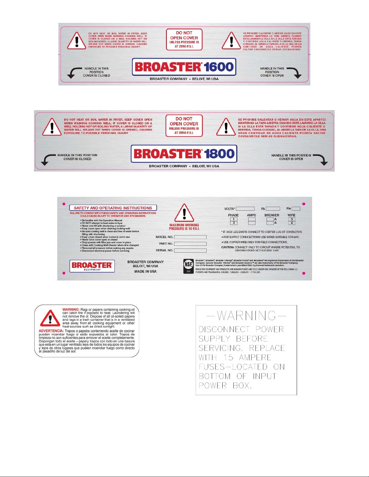
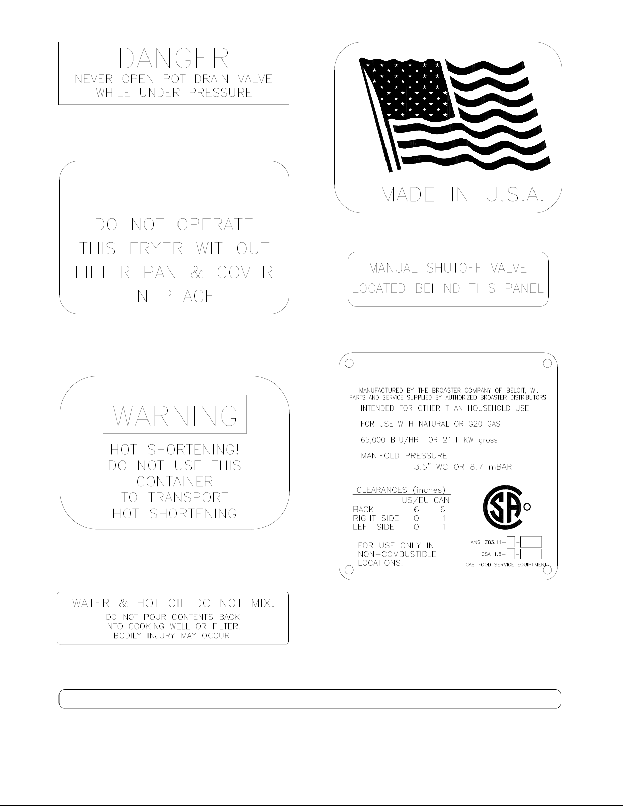
1800 Domestic Labeling
DO NOT OPERATE THIS FRYER WITH OUT FILTER PAN & COVER IN PLACE
CAUTION:
CAUTION
N
S
F
iyvhz{ly
jvtwhu
zthy{{v|jo
1-2
broaster.com Manual #17270 10/13 Rev 12/14
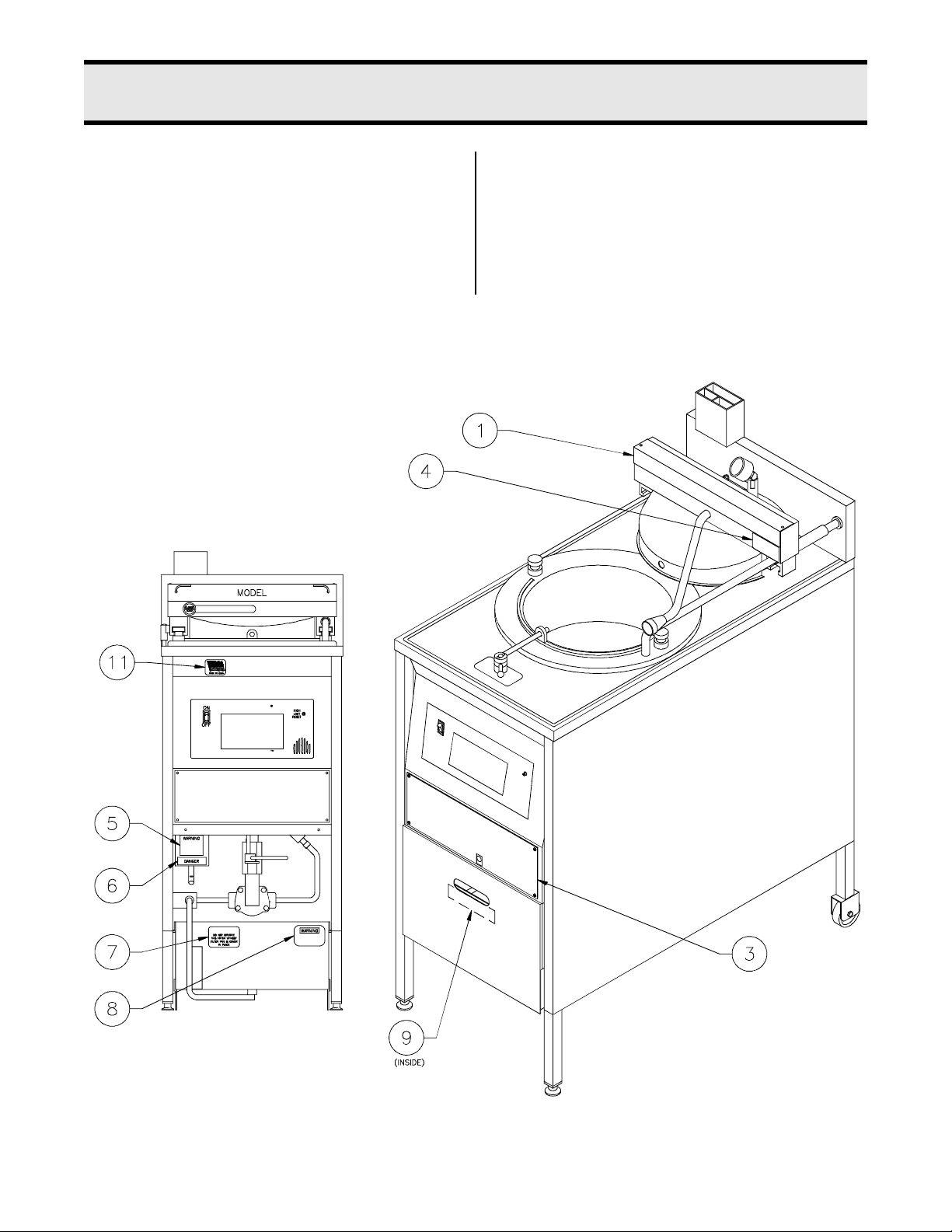
Item 1 - Part #10733
Item 2 - Part #10886
Item 3 - Part #11027
Item 4- Part #16368
Item 5 - Part #11073
1-3
broaster.com Manual #17270 10/13 Rev 12/14
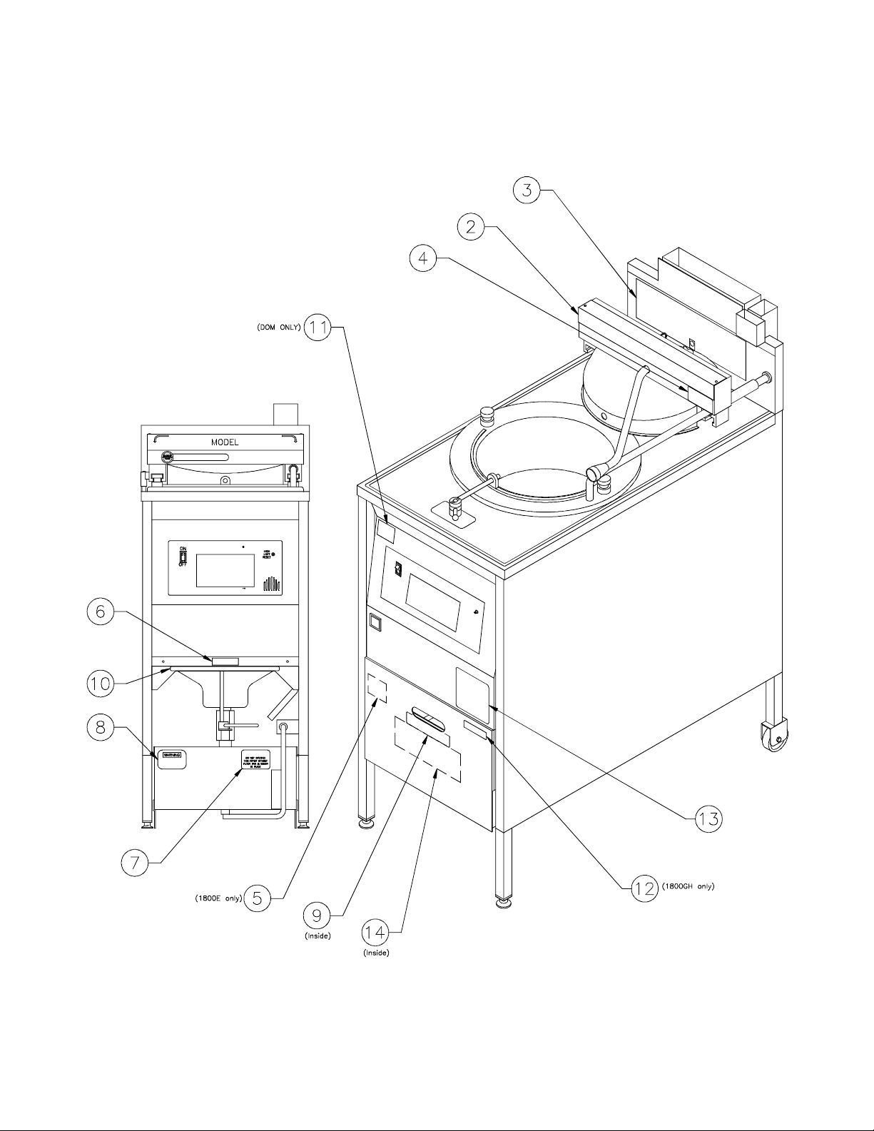
Item 6 - Part #06375
CAUTION
DO NOT OPERATE THIS FRYER WITHOUT FILTER PAN & COVER IN PLACE
CAUTION:
MODEL 1800GH
C US
R
Item 11 - Part #15398 Domestic Only
Item 7 - Part #15725
Item 8 - Part #11028
Item 12 - Part #11746 (1800GH Only)
Item 13 - (1800GH after July 2003)
#15777 for Nat Gas
#16993 for LP Gas
Item 9 - Part #10900
Item 10 - Part #15785
broaster.com Manual #17270 10/13 Rev 12/14
1-4

OPERATING INSTRUCTIONS
START UP
YOU ARE NOT REQURIED TO PHYSICALLY LIGHT THE PILOT ON THIS UNIT.
1. TURN THE MANUAL SHUT-OFF VALVE TO THE "ON" POSITION. WAIT
5 MINUTES BEFORE TURNING GAS VALVE ON.
2. MOVE SLIDE SWITCH ON GAS VALVE TO "ON"
3. MOVE COOK / FILTER SWITCH TO THE "COOK" POSITION.
SHUT DOWN
1. TURN COOK / FILTER SWITCH TO "OFF" POSITION.
2. MOVE SLIDE SWITCH ON GAS VALVE TO "OFF".
3. TURN THE MANUAL SHUT-OFF VALVE TO THE "OFF" POSITION.
INSTALL IN ACCORDANCE WITH AMERICAN NATIONAL STANDARD FUEL GAS CODE ANSI Z223. 1 LATEST ADDITION
Item 14 - Part #15694 Domestic
broaster.com Manual #17270 10/13 Rev 12/14
1-5

2 - ELECTRIC POWER SUPPLY
3Ph 50/60Hz
1Ph. 50/60Hz
Many sections in this
manual pertain to checking and repairing electrical components.
High voltage
will be encountered in several instances. Only persons trained and
equipped for checking high voltage shall
undertake such repairs.
If no component operates, check main
power supply. Be sure main circuit breaker
is ON and main fuses are good.
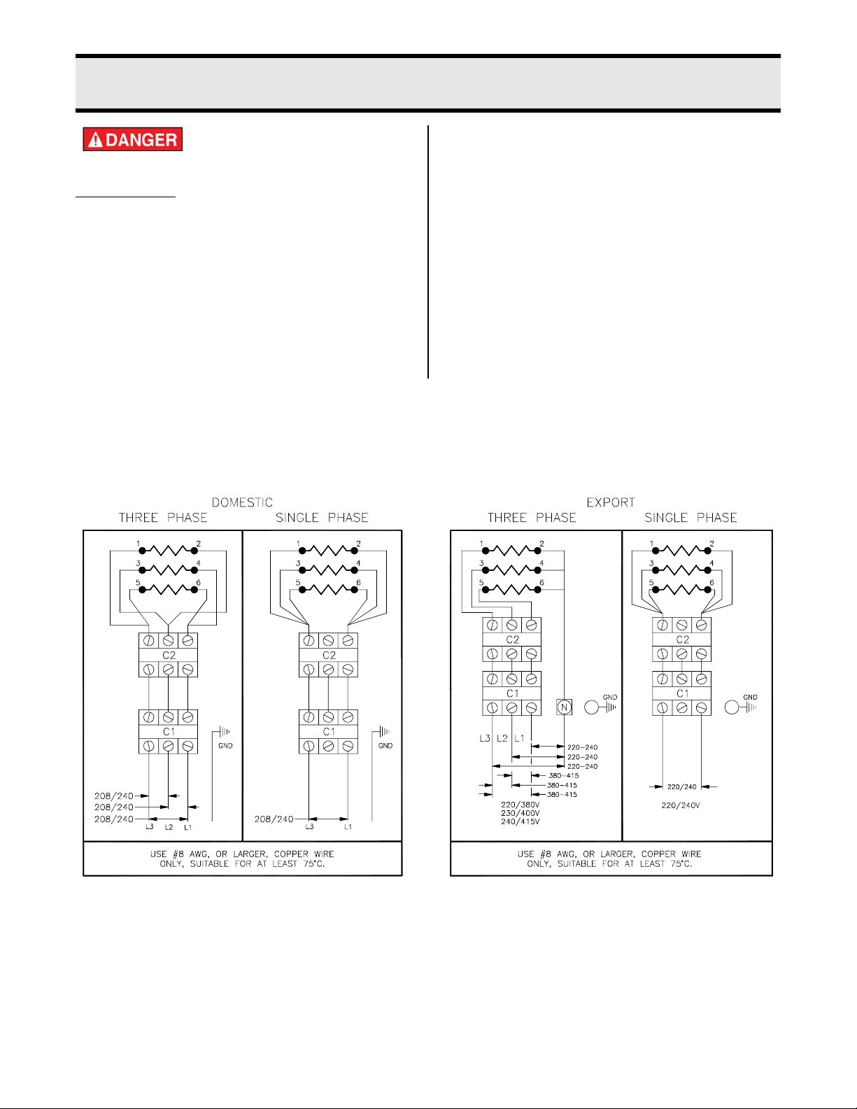
Correct voltage will be either 208 or 240V.
WIRING DIAGRAMS
Three and Single Phase Wiring Connections:
Perform the following if unit will not turn on:
1. Disconnect main power supply.
2. Be sure all connections are tight. If
power supply is proper, see TROUBLESHOOTING section.
Wiring diagrams are located on inside front
panel.
2-1
broaster.com Manual #17270 10/13 rev 6/15
NC
NO
C
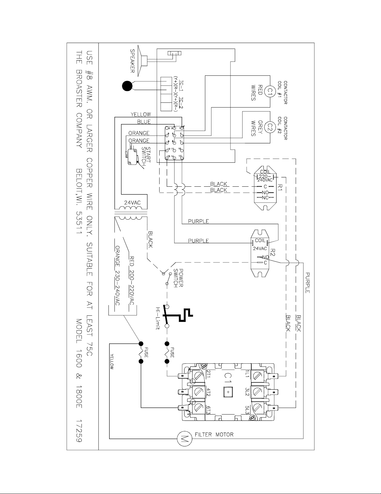
DOMESTIC - 1600 and 1800E SmartTouch
broaster.com Manual #17270 10/13 rev 6/15
2-2
EXPORT 1600XP SmartTouch
broaster.com Manual #17270 10/13 rev 5/16
2-3
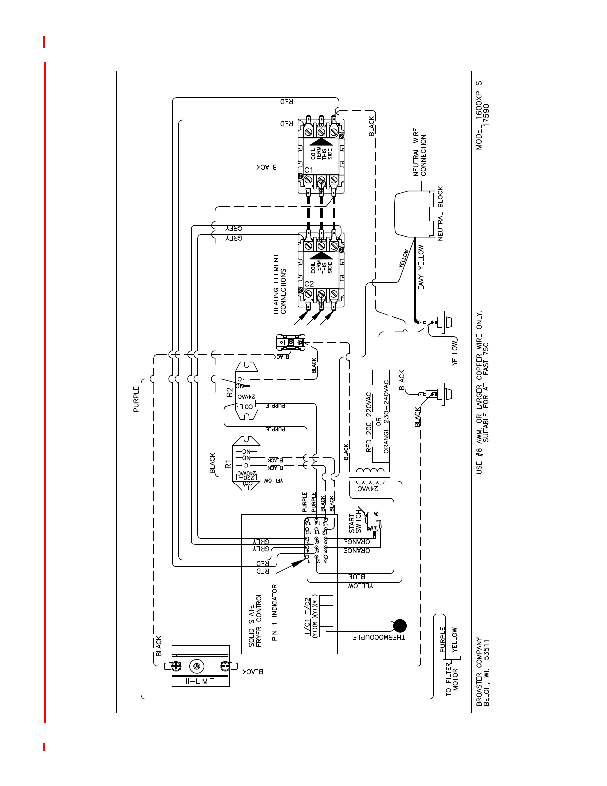
EXPORT 1800EXP SmartTouch
broaster.com Manual #17270 10/13 rev 5/16
2-4
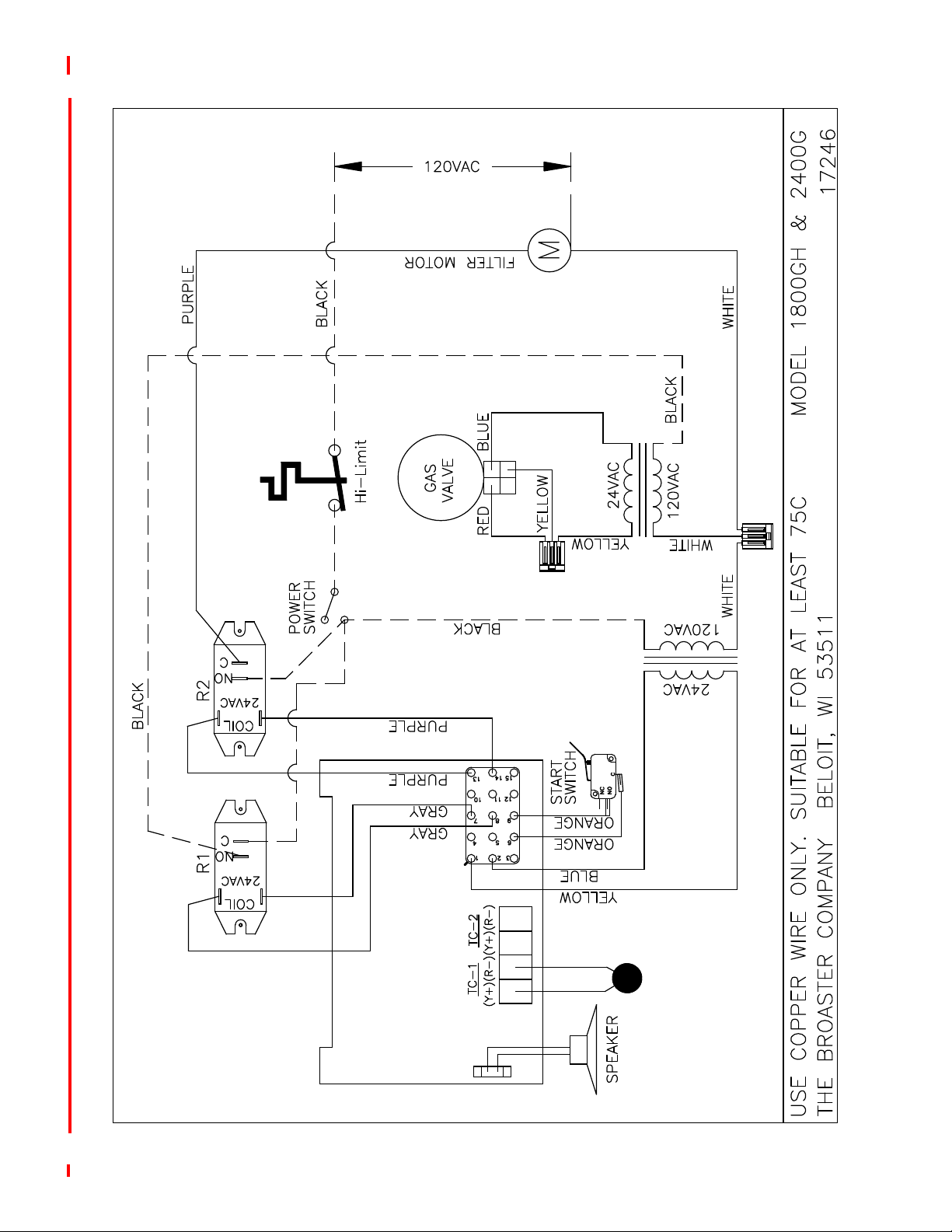
DOMESTIC - 1800GH SmartTouch
broaster.com Manual #17270 10/13 rev 5/16
2-5
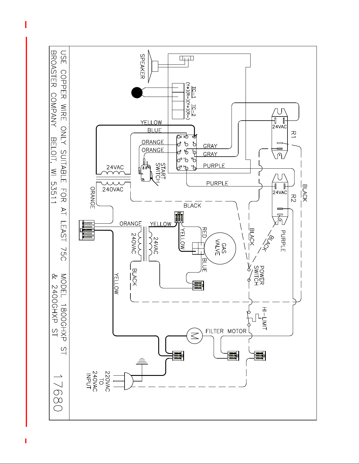
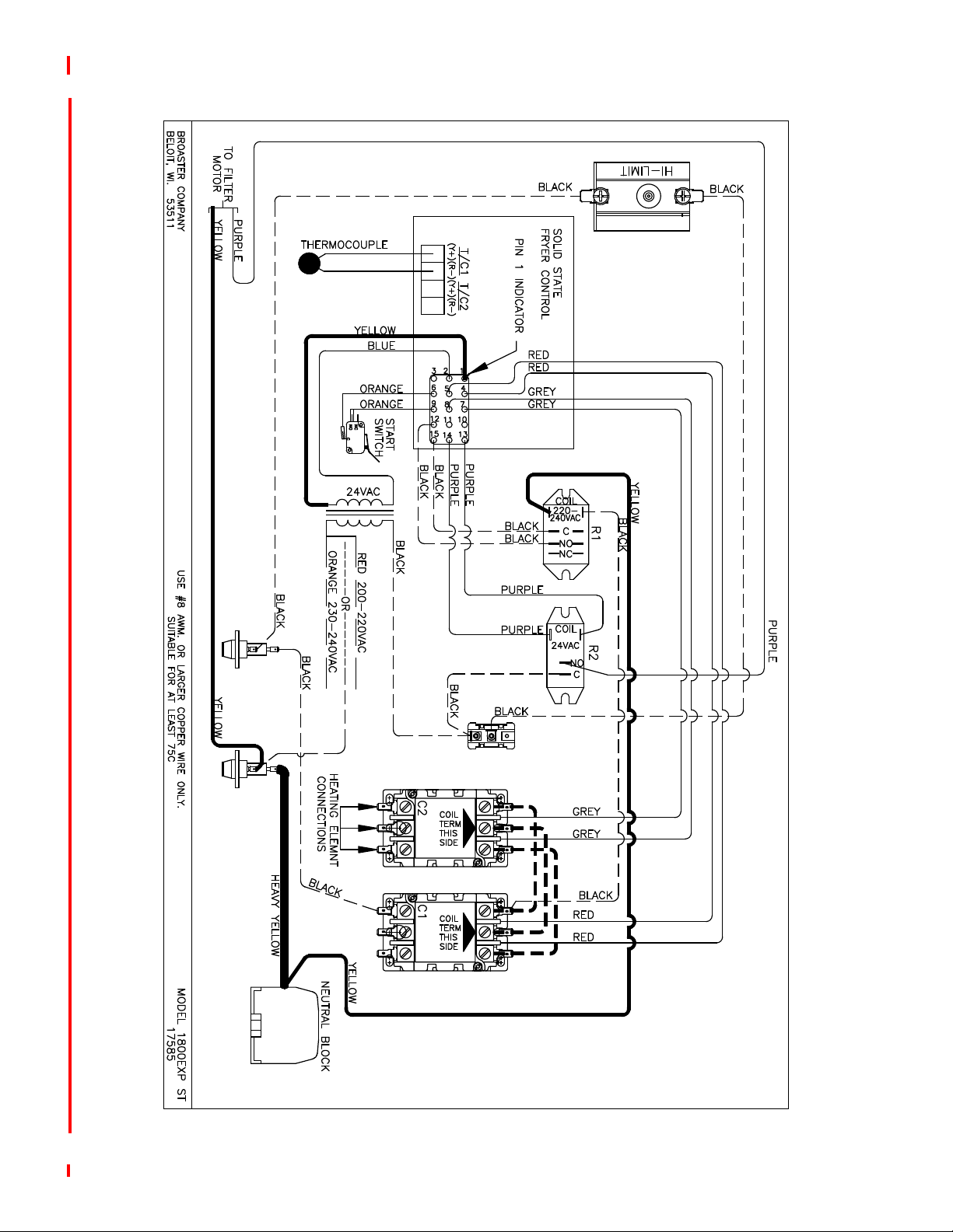
EXPORT - 1800GHXP SmartTouch
broaster.com Manual #17270 10/13 rev 5/16
2-6

3 - SMART TOUCH CONTROL PANEL
ON
OFF
HIGH
LIMIT
RESET
iyvhz{ly
jvtwhu
zthy{{v|jo
SMART TOUCH FAMILIARIZATION
1. Power Switch: This switch has two posi-
tions: ON or OFF.
2. Hi-Limit Control: Prevents oil temperature from exceeding 475°F. When this control trips, the power to the unit will be shut
down. Turn unit OFF and DO NOT attempt
to operate until it has been serviced by an
authorized Broaster Company representative.
It is possible for this con-
trol to trip during shipment. If it does, fully depress red reset
button. If control “clicks” it was tripped.
If not, it is correctly reset.
3. Touch Control Screen: Touching this
screen controls the many options of the
fryer.
On initial power up you may be asked to
enter the current date and time, and verify
the Serial Number. Or the screen will have
the word CAUTION flashing on the screen.
If the date and time entry screen appears
press the box after “Month” and a keypad
will appear. Enter the number of the month
and press the enter key. Repeat this action
for the Day, Year, Hours, Minutes, Seconds,
AM and PM boxes. When finished press the
green OK button in the bottom right corner
of the screen. The next display will ask you
if this date should be used to establish the
warranty start date. Press the green OK
button.
You will then see a display asking you to
verify the serial number of your fryer. Enter
the serial number using the keyboard and
press enter.
The date/time display and
the serial number display
will not appear again
when the power switch is turned off and
back on.
If the CAUTION screen appears it is there to
remind you to check the oil level before the
heating elements or burner are activated. If
the oil is at the proper level, press the green
OK button in the bottom right corner of the
screen.
Along the top of the screen are four tabs
(Cook, Filter, Setup and Help) to help you
setup and use your fryer.
This tab is the main working screen. From
broaster.com Manual #17270 10/13 Rev 12/14
3-1
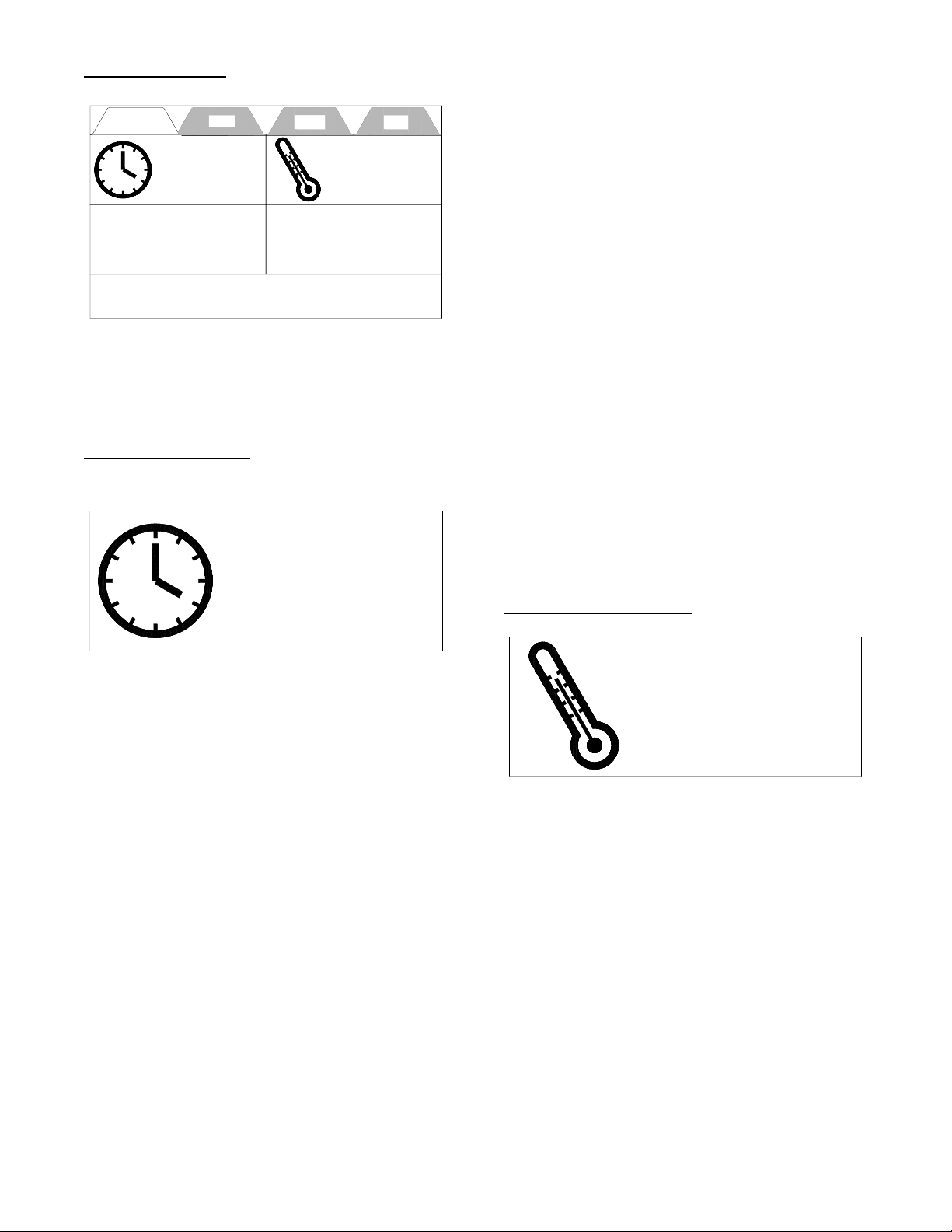
COOK TAB
05:00
Auto Comp ON
360F
Heat ON
Set
Select Preset
Select Preset
01
Cycles Since Last Filtered
Cook Filter Setup Help
05:00
Auto Comp ON
360F
Heat ONSet
At the end of the cycle the left box alternates between red and white, the alert
sounds and continues until the exhaust
valve is opened by turning the small handle
on the Counter Top, from “CLOSED” to
“OPEN”.
Auto Comp
In the upper right corner of the cook time
display is the Auto Comp indicator. It will be
black if Auto Comp is off and green if AutoComp is on.
this screen can be set the Cook Cycle Time,
Cook Temperature, Product Preset and the
number of loads cooked since the last time
the oil was filtered.
CookTime Display:
The cook time is indicated in the box next
to the clock face. To change the time press
the time display twice and a keypad will
appear.
Enter the cook time for the product you are
cooking, as you enter the time it will appear
above the keypad. To save this time press
the enter key the new time will be entered
and the keypad will disappear.
If no entry is made or the enter key is not
pressed with in 25 seconds, no change is
made to the time.
When a cooking cycle is started the box
below the cook time turns yellow and
shows the amount of time remaining in the
cycle. The right box displays “CUSTOM”.
The word “CUSTOM” also replaces the
tabs across the top of the display. “CUSTOM” indicates you are in manual cooking
mode.
To turn Auto Comp on or off press the cook
time display twice. When the keypad
appears the Auto Comp toggle switch is in
the upper right corner of the keypad. If the
button is red Auto Comp is off, if it is green
Auto Comp is on. Press the Auto Comp
button to change it then press the enter key.
Our recommendation is that Auto Comp
should be on when cooking a load of product.
Temperature Display:
The temperature is indicated next to the
thermometer.
When the fryer is turned on in the morning
this box will be yellow and “Heat On” will be
displayed. The temperature will alternate
between “LOW” and the set temperature
until the oil temperature reaches the set
temperature.
There are other times when this will occur;
1. Anytime the temperature is changed.
2. After a filtering cycle.
3. When a preset is selected and the oil
temperature is not at the preset temperature.
3-2
broaster.com Manual #17270 10/13 Rev 12/14

In any of these cases when the oil tempera-
Select Preset
01
Cycles Since Last Filtered
ture reaches the set temperature the box
turns green indicating the oil is up to the set
temperature.
The temperature shown in this box can be
either the “Set” temperature of the “Actual”
temperature as indicated above the thermometer. To change from one to the other
press anywhere in the box for 3 seconds.
An alert will sound when you press the box
and a second alert will sound when the
change is made.
To set the temperature, press the temperature box twice and a keypad will appear.
Enter the temperature for the product you
want to cook, as you enter the temperature,
it will appear above the keypad. To save this
temperature press the enter key.
Select Preset Display:
When the item has been selected a picture
of the item will appear in the left box and a
description of the item will appear in the
right box. When a cook cycle is started the
left box turns yellow and the time remaining
in the cycle is displayed. The picture moves
to the right box.
If the menu item to be cooked uses a different temperature the temperature box will
either remain green meaning it is all right to
start a cook cycle or it will turn yellow
meaning the temperature is too low to start
a load. Wait to start a cook cycle until the
temperature is green.
When the temperature is green. Load the
product as recommended and move the
small handle on the top of the fryer from
open to close. This will start the cycle timer
counting down. When the load is done an
alert will signal that the cooking cycle is
complete.
There are 2 “Select Preset” boxes.
All of the Broaster Company Products are
preloaded into the memory of the control
and can be selected when you want to
cook that product. The cook time and cook
temperature for that product will be automatically entered in the Time and Temperature displays.
To select a product, press either preset box
and a menu of the products will be displayed. Tap the product you wish to select.
If the wrong product comes up, don’t worry!
Tap the preset box again and the menu will
appear.
Cycles Since Last Filtered:
It is recommended the oil should be filtered
every 5 loads.
This box indicates how many cook cycles
have been done since the last time the oil
was filtered. It is active and can be pressed
at any time to go to the filter display except
during a cooking cycle. Once you reach a
preset number of cycles, you will be shown
a filter options screen. If a filter cycle is
bypassed the next cycle will turn red and
start flashing.
This number can be changed and the procedure will be explained in the Setup Tab
section.
broaster.com Manual #17270 10/13 Rev 12/14
3-3
Stop
Pump
X
Start / Stop Filter Pump
Filter Pump Running
00:00
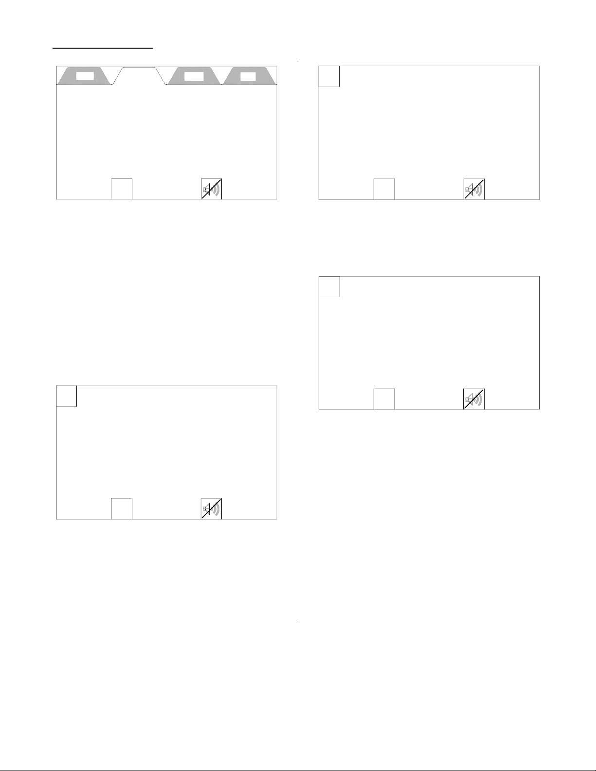
FILTER TAB
Cook Filter Setup Help
* Check Filter Pan & Components
* Stir Oil Before Opening Drain Valve
Start
Pump
Stop
Pump
X
Start / Stop Filter Pump
Filter Pump Running
00:00
Close Drain Valve
Start
Pump
X
Start / Stop Filter Pump
Filter Pump Run Time
10:00
Limit Reached
This tab is the filter motor control and has
two buttons; a Start Pump button and a
Alert Silence button.
There are also two reminders to observe
before filtering the oil. SEE SECTION 9 COOKING OIL CARE AND FILTERING
before starting the pump motor.
The pump will continue to run and will automatically stop when the counter says 10:00
minutes. You will see the display below.
When the Start Pump button is pressed the
filter running display appears as shown
below.
The timer in the middle of the screen starts
counting up. When it reaches 5:00 minutes
an alert sounds and a reminder flashes (see
below) to close the drain valve. To silence
the alert press the button with the speaker
on it. DO NOT press the Stop Pump button.
To return to the Cook Tab, press the red X in
the upper left corner. The Caution Display
will appear advising the oil level be
checked. If the oil level is OK press the
green OK button.
broaster.com Manual #17270 10/13 Rev 12/14
3-4
 Loading...