

Broaster 1600, 1800, 1800E, 1600XP, 1600CE Installation Manual
...
INSTALLATION MANUAL
BROASTER® 1600 AND 1800
PRESSURE FRYER
Be sure ALL installers read, understand, and have access to this manual at all times.
Genuine Broaster Chicken®, Broasted®, Broaster Chicken®, Broaster Foods®. and Broasterie® are registered
trademarks. Usage is available only to licensed operators with written authorization from the Broaster Company.
2855 Cranston Road, Beloit, WI 53511-3991
Design Certified By:
1600: CSA, NSF and UL
1800: CSA (AGA & CGA), NSF and UL
The Broaster Company
608/365-0193 broaster.com
#14678 1/99 Rev: 10/14
© 1999 the Broaster Company
Printed In U.S.A.

All adjustments and repairs shall be made
FOR YOUR SAFETY
Do not use or store gasoline or other flammable vapors
or liquids in the vicinity of this or any other appliance.
Improper installation, adjustments, alteration, service or maintenance can cause
property damage, injury or death. Read the installation, operating and maintenance instructions thoroughly before installing or servicing this equipment.
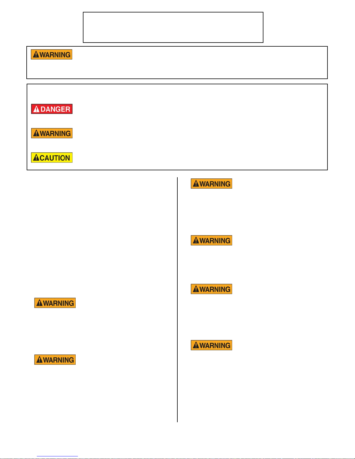
For the sake of safety and clarity, the following words used in this manual are defined as follows:
Indicates an imminently hazardous situation which, if not avoided, could
result in serious injury or death.
Indicates a potentially hazardous situation which, if not avoided, could
result in serious injury or death.
Indicates a potentially hazardous situation which, if not avoided, could
result in minor injury, property damage or both.
by an authorized Broaster Company representative.
when the cook/filter switch is moved to
If at any time the POWER
ON light does not turn off
the OFF position, contact your local
If there is a power failure, turn cook/filter
switch OFF. On the Model 2400GH, also
Broaster Company representative for
service immediately.
slide switch on gas valve OFF. DO NOT
attempt to operate unit during a power failure.
DO NOT operate unit
without filter pan and filter
pan cover in its proper position. Filter
2400GH: Post, in prominent locations,
instructions to be followed in the event that
pan cover must be wiped clean after
each filtering cycle.
the user smells gas. This information can be
obtained from your local gas supplier.
Make sure Pressure Relief
Valve and Pressure Gauge
Failure to read and
completely could result in serious injury
or death. Be sure ALL operators read,
understand this manual
ports on bottom of cover are clear of any
oil or grease buildup.
1600 Mechanical Controls:
understand and have access to this
manual at all times.
if exposed to heat. Laundering will not
remove the oil. Dispose of all oil-soiled
papers and rags in a trash container that
is in a ventilated area away from all
Rags or paper containing
cooking oil can catch fire
the cook/filter switch is moved to the
cook position, contact your local
If at any time the unit fails
to operate properly when
Broaster Company representative for
service immediately.
cooking equipment or other heat
sources such as direct sunlight.
W-1
broaster.com Manual #14678 1/99 Rev: 2/14

1600/1800E Solid State Controls:
If at any time the POWER
ON light does not turn off
when the cook/filter switch is moved to
the OFF position, contact your local
Broaster Company representative for
service immediately.
broaster.com Manual #14678 1/99 Rev: 2/14
W-2

TABLE OF CONTENTS
1 - PRE-INSTALLATION ....................................................................................................1 - 1
LOCATION...................................................................................................................1 - 1
CLEARANCE...............................................................................................................1 - 1
LEVELING ...................................................................................................................1 - 1
RECOMMENDED VENTILATION REQUIREMENTS....................................................1 - 2
General Requirements ........................................................................................1 - 2
1600 Hood Dimensions In Inches .......................................................................1 - 3
1800 Hood Dimensions In Inches .......................................................................1 - 4
1600/1800 Hood Dimensions In Millimeters .......................................................1 - 5
2 - FILTER PAN ASSEMBLY ..............................................................................................2 - 1
HARDWARE LIST........................................................................................................2 - 1
ASSEMBLY .................................................................................................................2 - 1
ADDITIONAL ADJUSTMENTS IF NEEDED.................................................................2 - 3
3 - 1600/1800E INSTALLATION.........................................................................................3 - 1
ELECTRICAL CHARACTERISTICS .............................................................................3 - 1
ELECTRICAL CONNECTIONS....................................................................................3 - 1
1600 Suggested Wiring Capacity Table..............................................................3 - 1
1800 Suggested Wiring Capacity Table..............................................................3 - 1
ELECTRICAL HOOK-UP .............................................................................................3 - 2
Access For Hook-Up ..........................................................................................3 - 2
Phase Wiring .......................................................................................................3 - 2
Unit Dimensions For Electrical Hook-Up ............................................................3 - 3
Wiring Diagrams
DOMESTIC:
1600 Mechanical ......................................................................................3 - 4
1600/1800E Solid State............................................................................3 - 8
EXPORT:
1600XP/1800EXP Mechanical ...............................................................3 - 12
1600XP/1800EXP Solid State ................................................................3 - 15
EU:
1600CE Mechanical ...............................................................................3 - 18
1600CE/1800ECE Solid State ................................................................3 - 19
United Kingdom:
1600UK/1800EUK ..................................................................................3 - 20
480V Units:
1800E 480V Δ.........................................................................................3 - 21
1600XP 240/480V...................................................................................3 - 22
1800XP 480V..........................................................................................3 - 24
broaster.com Manual #14678 1/99 Rev 3/14
i

4 - 1800GH INSTALLATION ...............................................................................................4 - 1
GENERAL REQUIREMENTS.......................................................................................4 - 1
EU: ......................................................................................................................4 - 1
USA & Canada ....................................................................................................4 - 1
ELECTRICAL CHARACTERISTICS .............................................................................4 - 2
ELECTRICAL CONNECTIONS....................................................................................4 - 2
WirIng Diagrams ....................................................................................................4 - 2
DOMESTIC: 1800GH .........................................................................................4 - 2
EXPORT: 1800GH .............................................................................................4 - 3
EU: 1800GHCE .................................................................................................4 - 4
EU: 1800GHCE for United Kingdom..................................................................4 - 5
GAS CHARACTERISTICS ...........................................................................................4 - 6
BTU/HR Ratings..................................................................................................4 - 6
Gas Pressure And Orifices..................................................................................4 - 6
Gas Conversion ..................................................................................................4 - 6
High Altitude .......................................................................................................4 - 6
GAS PIPING ................................................................................................................4 - 7
Unit Dimensions For Gas Hook-Up ....................................................................4 - 7
Example Of Piping System Design .....................................................................4 - 8
5 - OPERATIONAL CHECK-OUT ......................................................................................5 - 1
COVER ASSEMBLY ....................................................................................................5 - 1
INITIAL STARTUP
Electric .............................................................................................................. 5 - 1
Gas .....................................................................................................................5 - 2
1800GH LIGHTING INSTRUCTIONS ..........................................................................5 - 2
Start-Up ..............................................................................................................5 - 2
Shut Down ..........................................................................................................5 - 3
AIR SHUTTER ADJUSTMENT ...................................................................................5 - 3
broaster.com Manual #14678 1/99 Rev: 3/14
ii

1 - PRE-INSTALLATION
LOCATION
For convenience and speed, location of the
unit should be given careful consideration.
If possible, locate the unit so the flow of
cooked product is in a straight line from
storage, in and out of the unit and to the
customer. Landing tables should be provided on at least one side of the unit.
• To avoid splashing of hot liquid, unit
must be restrained to prevent tipping.
This can be done by installing the unit in
a battery of appliances, in an alcove or
with adequate ties
• Provision must be made to eliminate
movement of the unit which might cause
strain on electrical and gas connections.
• DO NOT install unit where traffic areas
are on either side or in back of unit.
CLEARANCE
USA & EU:
Gas units are to be installed only in noncombustible locations. Minimum clearances for non-combustible construction is 0 inches from sides and 6 inches
from back.
CANADA:
Gas units are certified for installation on
a combustible floor. Minimum clearances for combustible construction is 1
inch from sides and 6 inches from back.
LEVELING
Adjust front feet to level entire unit. Add
additional blocking if necessary on a sloping floor.
1-1
broaster.com Manual #14678 1/99 Rev 2/14

RECOMMENDED VENTILATION
General Requirements:
REQUIREMENTS
Exhaust hood should comply with ANSI/
NFPA #96 or national, state and local
codes. All units must be under an adequate
power exhaust hood for ventilation of cooking vapors and products of combustion.
Precautions should be taken in the design
of the exhaust hood to avoid interference
with operation of the unit. Consult a local
ventilation company for fire suppression,
design and installation of a hood.
DO NOT extend the
exhaust stack or exhaust
flue of any unit. Doing so may cause a negative back draft causing malfunction and
interference with burner operation on the
1800GH and improper exhausting of cooking vapors on all units.
1. Exhaust hood must conform to applicable national, state and local codes.
2. It is recommended that requirements
of the National Fire Protection Association (NFPA), Standard No. 96 be followed for the design, installation and
use of exhaust system components.
This includes hoods, grease removal
devices, exhaust ducts, dampers, air
moving devices, auxiliary equipment
and fire extinguishing equipment for
the exhaust system and the cooking
equipment used therewith in commercial, industrial, institutional and similar
cooking applications.
3. Hood Size: The overhead canopy
type hood should be sized to completely cover the equipment it is
designed to ventilate plus an overhang
of at least 6 inches on all sides of
equipment not immediately adjacent
to walls or other construction extending above the cooking surface. Noncanopy, prefabricated “backshelf”
type hoods should be sized according
to the manufacturers specifications.
4. Exhaust Air Volume (minimum):
Canopy hood open on all four sides:
1800 cu. ft./minute. Canopy hood
open on three sides or less: 1200 cu.
ft./minute.
5. Exhaust Air Velocity: All exhaust
ducts should be sized to provide an air
velocity in the ducts of at least 1500
ft./minute.
1-2
broaster.com Manual #14678 1/99 Rev 2/14
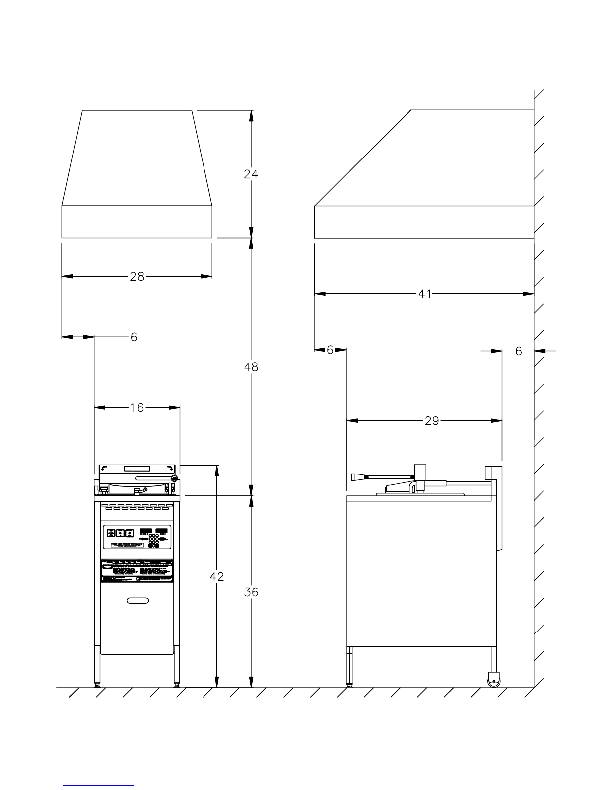
1600 Hood Dimensions In Inches:
DANGER
MAXIMUM WORKING
PRESSURE 15 PSI
BEFORE OPERATINGCHECK OIL LEVELCAUTION!
0
21
475
8
3
6
9
MADE IN U.S.A.
SAFETY AND OPERATIN G INSTRUCTIONS
NSF
MANUFACT URED BY THE BROA STER COM PANY
MODEL 1600
UNLESS PRESSURE IS AT ZERO P.S.I.
DO NOT O PEN COVER
COVER CLOSED
COVER OPEN
1-3
broaster.com Manual #14678 1/99 Rev 2/14

1800 Hood Dimensions In Inches:
1-4
broaster.com Manual #14678 1/99 Rev 2/14
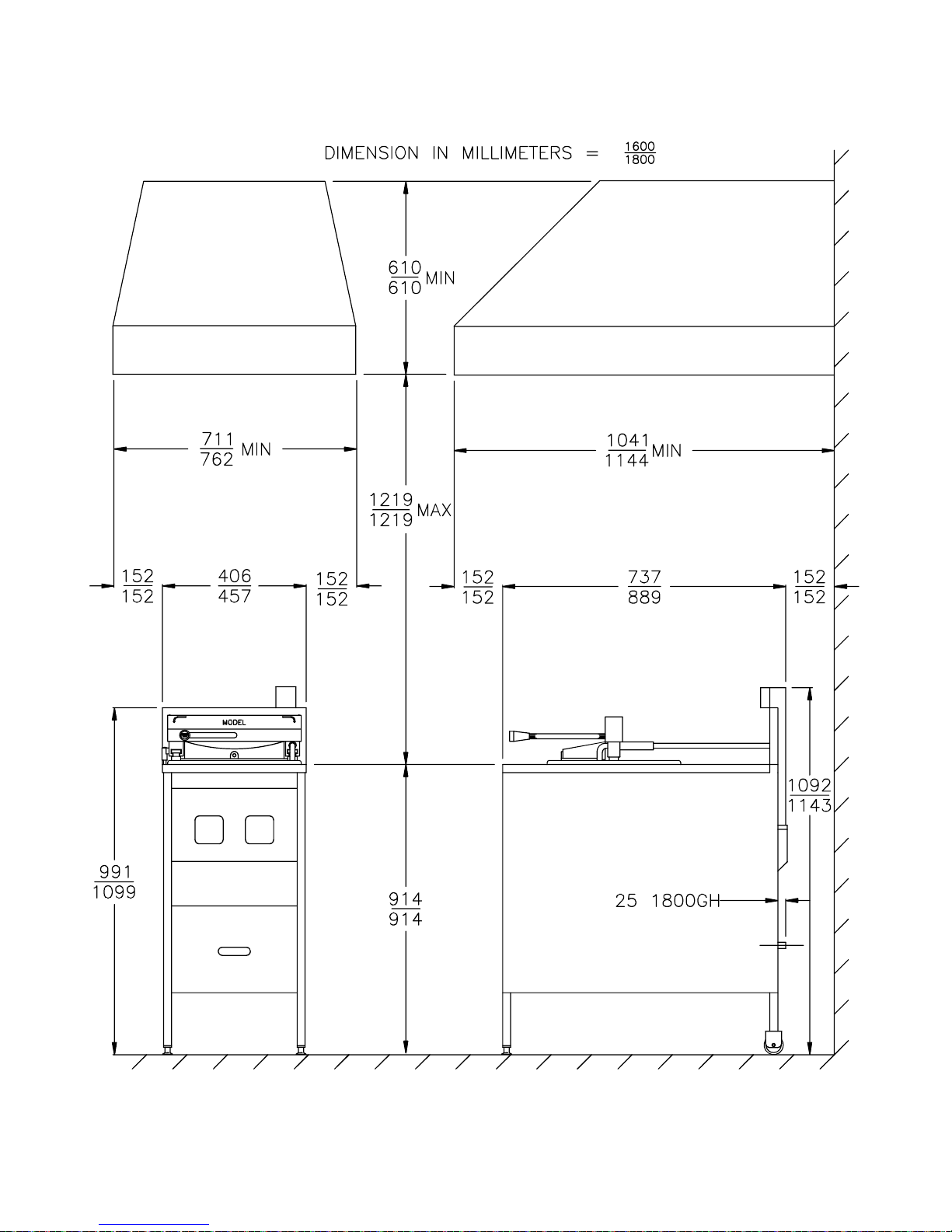
1600/1800 Hood Dimension In
Millimeters:
1-5
broaster.com Manual #14678 1/99 Rev 2/14

2 - FILTER PAN ASSEMBLY
HARDWARE LIST
1600:
1 - Compression Nut #02536 (1)
2 - Brass Ferrule #02537 (1)
3 - Riser Line #11314 (1)
6 - Keps Nut #00522 (2)
7 - O-ring #09883 (3)
9 - Nipple #08696 (1)
1800:
1 - Compression Nut #02536 (1)
2 - Brass Ferrule #02537 (1)
3 - Riser Line #11308 (1)
6 - Keps Nut #00522 (2)
7 - O-ring #09883 (3)
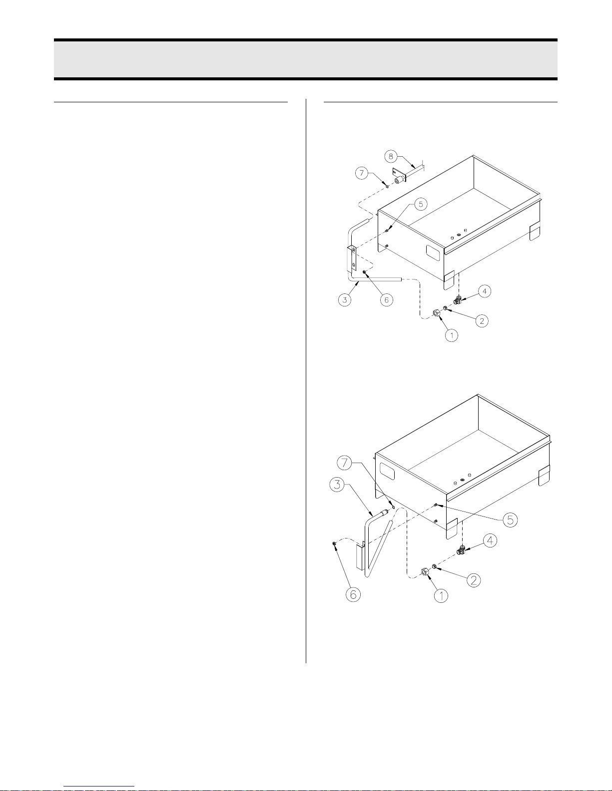
ASSEMBLY
1600:
1800:
1. From bag of hardware, install compression nut (1) then ferrule (2) onto
riser line (3).
2-1
broaster.com Manual #14678 1/99 Rev 2/14
2. Install riser line (3) onto pan. First
install line into elbow (4) on bottom
center of pan while handle fits over
studs (5) on front of pan.
3. Install keps nuts (6) onto studs (5) but
do not tighten.
4. Tighten nut onto elbow (4).
Elbow may have to be
turned with a wrench if nut
will not start onto elbow.
5. .Lubricate O-ring (7) with cooking oil.
1600: Install O-ring (7) into inner
groove in suction line (6). Screw nipple
(9) into drain valve (10).
1800: Install O-ring (7) into groove on
riser line (3).
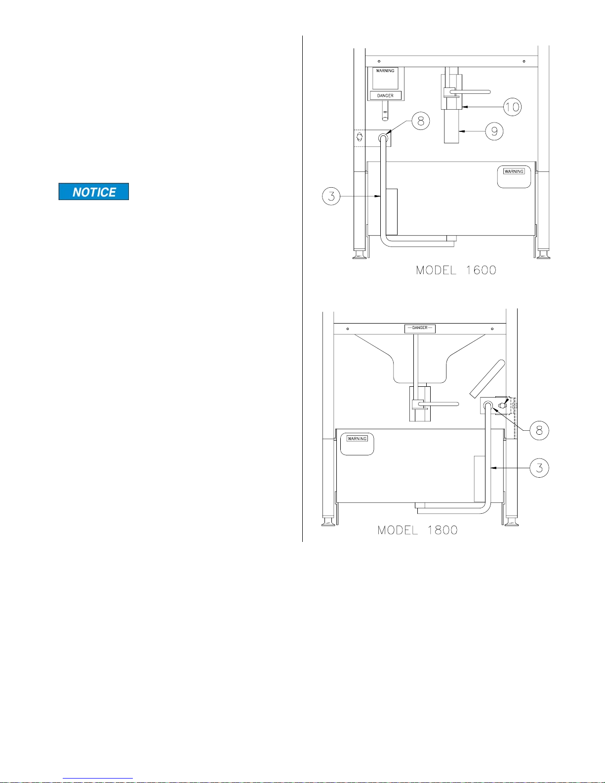
6. Install filter pan under unit and align
riser line (3) with suction line (8).
7. Tighten keps nuts (6) mounting riser
line (3) to filter pan.
8. See Operation Manual for additional
assembly.
2-2
broaster.com Manual #14678 1/99 Rev 2/14
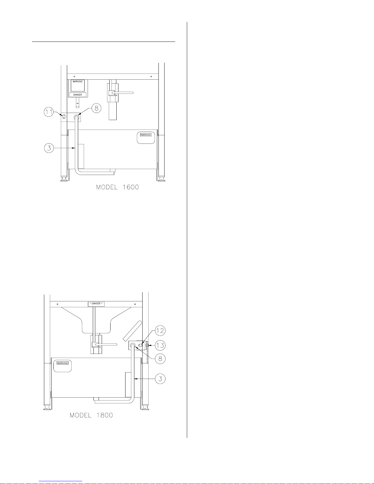
ADDITIONAL ADJUSTMENTS
2. Loosen bolt (12) and nut and bolt (13).
IF NEEDED
1600:
1. Loosen nut and bolt (11).
3. Push pan under unit. By hand, move
suction line (8) until riser line (3) is fully
inserted into suction line.
4. Tighten all nuts and bolts.
5. Replace side panel
2. Push pan under unit. By hand, move
suction line (8) until riser line (3) is fully
inserted into suction line.
3. Tighten all nuts and bolts.
1800:
1. Remove side panel.
2-3
broaster.com Manual #14678 1/99 Rev 2/14


3 - 1600/1800E INSTALLATION
ELECTRICAL CHARACTERISTICS
These models are available for either 208,
240 or 480 applied voltage, 60Hz, 3 phase
electrical connection in the USA and several voltages for export applications.
Be sure to check the wiring diagram located
inside the front panel. It shows electrical
circuits and connections. See Access For
Hook-Up under ELECTRICAL HOOK-UP.
• All electrical work must conform with the
requirements of national, state and local
electrical codes.
• When installing or servicing the unit,
always check the dataplate located on
the front panel (1600) or toward the rear
of the counter top (1800) to make certain proper parts are used and the correct service rendered. DO NOT apply a
voltage to any unit other than that
shown on the dataplate. If in doubt,
consult your local power company.
1600 Suggested Wiring Capacity Table:
Phase Volts Amps Wire
1 208 29 #8 40
1 220 30.5 #8 40
1 230 26 #8 40
1 240 27 #8 40
3 208 17 #10 25
3 240 16 #10 20
3 220/380 10.2 #10 15
3 230/400 8.7 #10 15
3 240/415 9.1 #10 15
Breaker
or Fuse
1800E Suggested Wiring Capacity Table:
Phase Volts Amps Wire
1 208 48 #8 60
Breaker
or Fuse
ELECTRICAL CONNECTIONS
• A remote circuit breaker or fuse should
be installed in main power supply
located in a path of exit and clearly identified.
• When installed, the unit must be electrically grounded in accordance with local
codes, or in the absence of local codes,
with the National Electrical Code, ANSI/
NFPA 70, or for Canada, the Canadian
Electrical Code, CSA C22.2, as applicable.
• Use copper wire only for connections.
• If power run is over 50 feet, use next
larger size wire.
1 220 50 #8 60
1 230 43 #8 60
1 240 45 #8 60
3 208 28 #8 40
3 240 26 #8 40
3 220/380 16.8 #10 20
3 230/400 14.3 #10 20
3 240/415 15 #10 20
broaster.com Manual #14678 1/99 Rev 2/14
3-1
 Loading...