

Broan EC62 SERIES, elite EC622301SS, elite EC621306SS Installation Instructions Manual
EC62 SERIES
INTENDED FOR DOMESTIC COOKING ONLY
INSTALLER: LEAVE THIS MANUAL WITH HOMEOWNER.
HOMEOWNER: USE AND CARE INFORMATION ON PAGES 12 AND 13.
Broan-NuTone Canada Inc.; Mississauga, Ontario www.broan.ca 877-896-1119
www.broan.ca
REGISTER YOUR PRODUCT ON LINE AT: www.broan.com/register
SV08970 rev. B
HB0091
INSTALLATION INSTRUCTIONS
READ AND SAVE THESE INSTRUCTIONS
!
!

WARNING WARNING
- 2 -
TO REDUCE THE RISK OF FIRE, ELECTRIC
SHOCK OR INJURY TO PERSONS, OBSERVE
THE FOLLOWING:
1. Use this unit only in the manner intended by the
manufacturer. If you have questions, contact the
manufacturer at the address or telephone number
listed in the warranty.
2. Before servicing or cleaning unit, switch power off
at service panel and lock service disconnecting
means to prevent power from being switched on
accidentally. When the service disconnecting
means cannot be locked, securely fasten a prominent
warning device, such as a tag, to the service panel.
3. Installation work and electrical wiring must be done
by qualified personnel in accordance with all
applicable codes and standards, including fire-rated
construction codes and standards.
4. Sufficient air is needed for proper combustion and
exhausting of gases through the flue (chimney) of
fuel burning equipment to prevent backdrafting.
Follow the heating equipment manufacturer’s
guidelines and safety standards such as those
published by the National Fire Protection
Association (NFPA), and the Amer ican Society for
Heating, Refrigeration and Air Conditioning
Engineers (ASHRAE), and the local code authorities.
5. When cutting or drilling into wall or ceiling, do not
damage electrical wiring and other hidden utilities.
6. Ducted fans must always be vented to the
outdoors.
7. WARNING - To reduce the risk of fire or electric
shock, do not use this unit with any additional solid-state
speed control device.
8. WARNING - TO REDUCE THE RISK OF FIRE,
USE ONLY METAL DUCTWORK.
9. This unit must be grounded.
10.
When applicable local regulations comprise more
restrictive installation and/or certification requirements,
the aforementioned requirements prevail on those
of this document and the installer agrees to
conform to these at his own expenses.
WARNING - TO REDUCE THE RISK OF A
RANGE TOP GREASE FIRE:
a) Never leave surface units unattended at high settings.
Boilovers cause smoking and greasy spillovers that
may ignite. Heat oils slowly on low or medium settings.
b) Always turn hood ON when cooking at high heat or
when flambeing food (i.e. Crêpes Suzette, Cherries
Jubilee, Peppercorn Beef Flambé).
c) Clean ventilating fans frequently. Grease should not
be allowed to accumulate on fan or filters.
d) Use proper pan size. Alw ays use cookw are appropriate
for the size of the surface element.
TO REDUCE THE RISK OF INJURY TO PERSONS
IN THE EVENT OF A RANGE TOP GREASE
FIRE, OBSERVE THE FOLLOWING*:
1. SMOTHER FLAMES with a close-fitting lid,
cookie sheet or metal tray, then turn off the
burner. BE CAREFUL TO PREVENT BURNS. IF
THE FLAMES DO NOT GO OUT IMMEDIATELY,
EVACUATE AND CALL THE FIRE DEPARTMENT.
2. NEVER PICK UP A FLAMING PAN – You may
be burned.
3. DO NOT USE WATER, including wet dishcloths or
towels – This could cause a violent steam explosion.
4. Use an extinguisher ONLY if:
A. You own a Class ABC extinguisher and
you know how to operate it.
B. The fire is small and contained in the area
where it started.
C. The fire department has been called.
D. You can fight the fire with your back to an exit.
* Based on “Kitchen Fire Safety Tips” published by NFPA.
CAUTION
1. For indoor use only.
2. For general ventilating use only. Do not use to exhaust
hazardous or explosive materials and vapors.
3. To avoid motor bearing damage and noisy and/or
unbalanced impellers, keep drywall spray,
construction dust, etc. off power unit.
4. Your power pack motor has a thermal overload
which will automatically shut off the motor if it
becomes overheated. The motor will restart when it
cools down. If the motor continues to shut off and
restart, have the power pack serviced.
5. The minimum hood distance above cooktop must
not be less than 24”. A maximum of 30” above
cooktop is highly recommended for best capture of
cooking impurities.
6. Two installers are recommended because of the
large size and weight of this unit.
7. To reduce the r isk of fire and to properly exhaust
air, be sure to duct air outside – Do not exhaust air
into spaces within walls or ceiling or into attics,
crawl space or garage.
8. This product is equipped with a thermostat which
may start blower automatically. To reduce the risk
of injury and to prevent power from being switched
on accidentally, switch power off at service panel
and lock or tag service panel.
9. Because of the high exhausting capacity of this
unit, you should make sure enough air is entering
the house to replace exhausted air by opening a
window close to or in the kitchen.
10. To reduce the r isk of fire and electrical shock, the
Broan Elite EC62 Series models must be installed
only with their own built-in blow er(s). Other blowers
cannot be substituted.
11. Please read specification label on product for
further information and requirements.
!
!
- 3 -
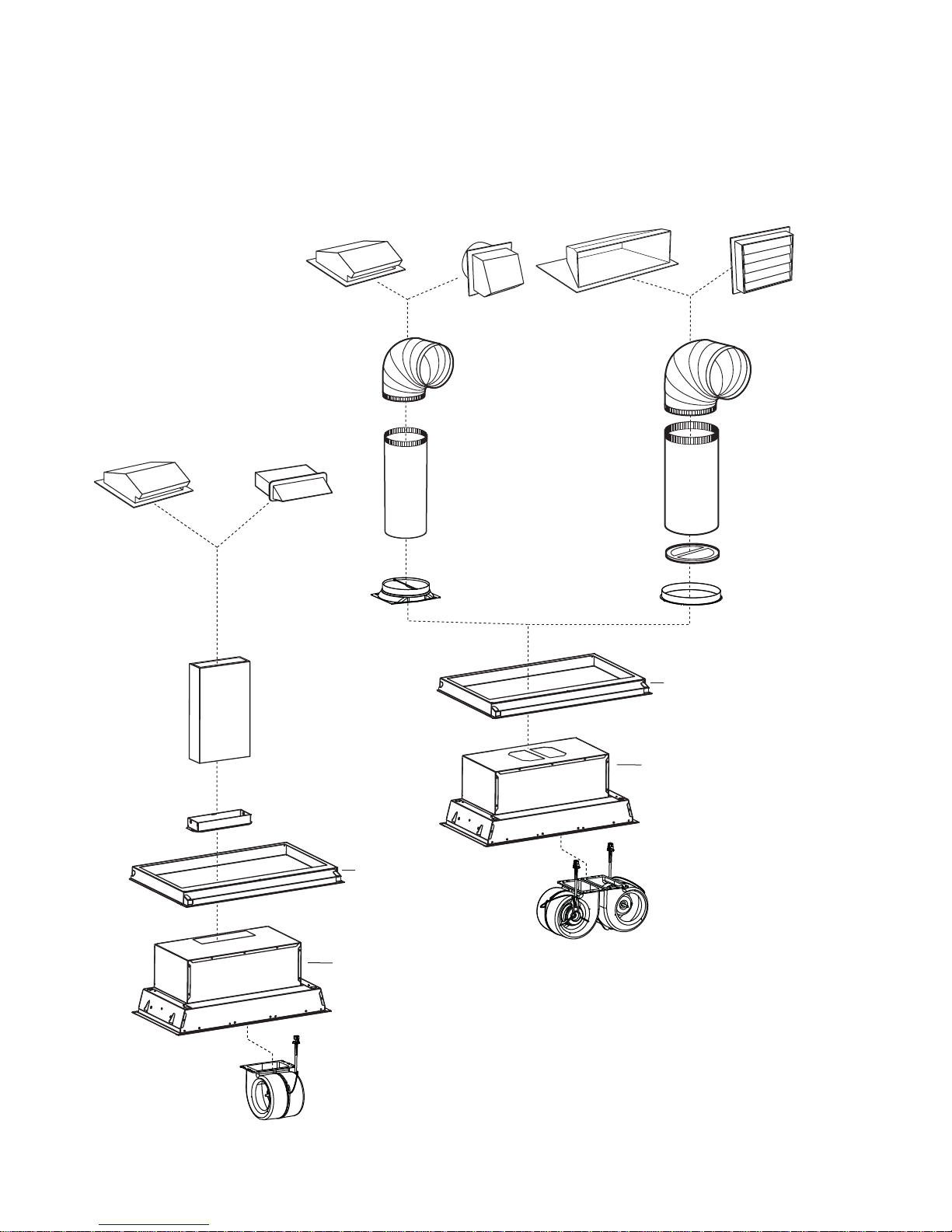
- EC62 SERIES POWER PACK SYSTEM -
MODEL 634 OR 644
ROOF CAP
(NOT INCLUDED)
M
ODEL 643
8” ROUND WALL CAP
(NOT INCLUDED)
3¼”
X 10” ADAPTER AND DAMPER
(SUPPLIED WITH SINGLE BLOWER
POWER PACK
)
S
INGLE BLOWER
(600 CFM, SUPPLIED
WITH POWER PACK
)
D
UAL BLOWER
(900 CFM OR 1100 CFM,
SUPPLIED WITH POWER PACK)
L6230SS,
L6236SS
OR L6242SS
CUSTOM HOOD LINER
(OPTIONAL)
8” R
OUND
ADAPTER AND DAMPER
(SUPPLIED WITH 900 CFM
DUAL BLOWER POWER PACK
)
S
TANDARD
3¼” X 10” DUCT
(NOT INCLUDED)
EC622309SS OR
EC622301SS
POWER PACK
EC621306SS
POWER PACK
STANDARD
3¼” X 10” ROOF CAP
(NOT INCLUDED)
STANDARD
3¼” X 10” WALL CAP
(NOT INCLUDED)
M
ODEL 437
HIGH CAPACITY ROOF CAP
(NOT INCLUDED)
MODEL 441
10” ROUND WALL CAP
(NOT INCLUDED)
8” R
OUND
ADJUSTABLE ELBOW
(NOT INCLUDED)
8” R
OUND
STANDARD DUCT
(NOT INCLUDED)
M
ODEL 418
10” ROUND
ADJUSTABLE ELBOW
(NOT INCLUDED)
M
ODEL 410
10” ROUND DUCT
— 2 FT. SECTIONS
(NOT INCLUDED)
10” R
OUND VERTICAL
IN-LINE DAMPER
(SUPPLIED WITH 1100 CFM
DUAL BLOWER POWER PACK
)
10” R
OUND ADAPTER
(SUPPLIED WITH 1100 CFM
DUAL BLOWER POWER PACK
)
L6230SS,
L6236SS OR L6242SS
CUSTOM HOOD LINER
(OPTIONAL)
HL0126
- 4 -
1. PREPARE THE INSTALLATION
2. INSTALL DUCTWORK AND ELECTRICAL WIRING
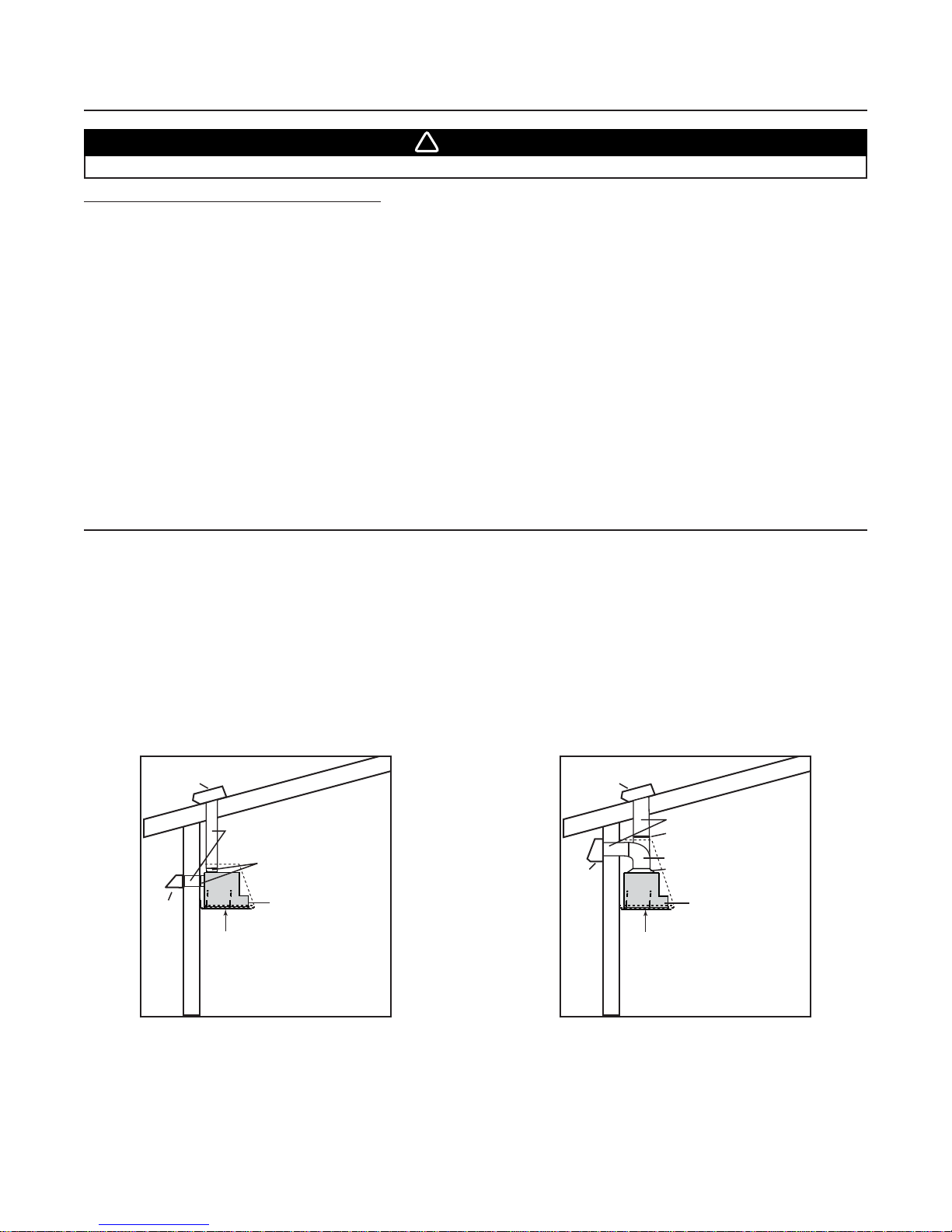
Plan where and how the ductwork will be installed. Access to the top of the hood is preferred for connection of ductwork.
Install proper-sized ductwork, elbows and roof or wall cap for the type of po w er pac k y ou are installing. If installing EC621306SS
single blower power pack, use 3¼” x 10” ductwork. For double blower power packs, if installing EC622309SS, use 8” round ductwork
and if installing EC622301SS, use 10” round ductwork. Use 2” metal duct tape to seal duct joints.
The minimum hood distance above cooktop must not be less than 24”.
A maximum of 30” above cooktop is recommended for best capture of cooking impurities.
Distances over 30” are at the installer and users discretion.
Run 3-wire power supply cable to installation location. Its length should extend at least 4 feet below the bottom of the custom
hood.
Power pack
Roof cap
Wall
cap
HH0116A
3¼” x 10”
adapter & damper
24” to 30”
above
cooking surface
3¼” x 10” duct
MODEL EC621306SS
(SINGLE BLOWER) TYPICAL DUCTWORK
Power pack
Roof cap
Wall
cap
HH0117A
8” or 10” round duct
8” round adapter & damper
or 10” round adapter
24” to 30”
above
cooking surface
8” or 10” round elbow
10” in line
vertical damper
MODEL EC622309SS OR EC622301SS
(DUAL BLOWER) TYPICAL DUCTWORK
Make sure that the following items are included:
- Power Pack
- Accessories: • 2 Filters
• 2 Filter knobs with screws, taped inside the hood
• 2 Shielded halogen lamps (120 V, 50 W, MR16 with GU10 base)
• 3¼” x 10” adapter and damper (supplied witih600 CFM single blower power pack)
• 8” round adapter and damper (supplied with 900 CFM dual blower power pack)
• 10” round in-line vertical damper (supplied with 1100 CFM dual blower power pack)
• 10” round adapter (supplied with 1100 CFM dual blower power pack)
• Bag of parts including: (1) wire clamp, (2) wire connectors, (4) no. 8 x 3/8” screws,
(9) no. 8 x 1/2” chrome plated screws, (10) no. 8-32 x 1/4” screws. If need be, discard extra screws.
Parts sold separately:
- Custom hood liner Model L6230SS, L6236SS or L6242SS (optional)
- Ducts, elbows, wall and roof caps. Refer to page 3 for a complete list of venting options and model numbers.
NOTE: During installation, protect countertop and/or cooktop.
When performing installation, servicing or c leaning the unit, it is recommended to wear safety glasses and glo ves.
WARNING
!
NOTE: Although the horizontal discharge installation is feasible with EC621306SS power pack model, this installation
type should be performed in specific situation only since it requires particular knowledge and technical skills
from the installers.
NOTE: The dual blower models have the same dimensions than the single blow er model, b ut do not ha ve a horizontal discharge.
Refer to single blow er pow er pack illustr ation f or bac k and side vie ws, and discard horizontal discharge measurements .
3. CUSTOM HOOD PREPARATION
WARNING
When building a custom hood, always follow all applicable construction codes and standards. The custom
hood must be p o s itively secured to wall studs or other wooden framework behind the drywall. Make sure
it is capable of supporting its own weight and the weight of the power pack. Failure to do so may cause
personal injury or damage to countertop or cooktop.
!
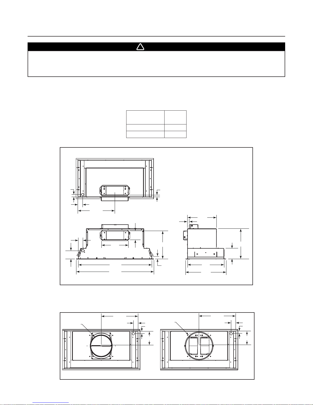
The custom hood must be constructed to fit the shape and total weight of the EC62 power pack model. The recommended
minimum thickness for the custom hood base is 5/8”. If an optional custom hood liner will be installed, we recommend the sides
and front of the custom hood to be 3/4” thick. If the optional custom hood liner will not be installed, the custom hood sides and
front thickness are at the installer’s discretion. See char t and illustration for details.
POWER PACK
TYPES
TOTAL
WEIGHT
SINGLE BLOWER 33 LB
DUAL BLOWER 45 LB
- 5 -
SINGLE BLOWER POWER PACK
DUAL BLOWER POWER PACKS
TOP VIEW
HK0114A
13 5/16”
1¾”
7/8”
5¼”
13 5/16”
1¾”
7/8”
5¼”
ø10”
ø 8”
TOP VIEW
7/8”
1¾”
15
/16”
2
1¾”
13 5/16”
TOP VIEW
9¾”
5/8”
3 ³/
16”
10 1/8”
10½”
5/8”
3 ³/
16”
10
15
/16”
HK0104A
5
/8”
26
28 1/8”
BACK VIEW SIDE VIEW
11/16”
13¼”
14¾”
 Loading...