

Broan 744C Instructions Manual

MODEL 744C
®
Page 1
RECESSED
FAN / LIGHT
READ AND SAVE
THESE INSTRUCTIONS
WARNING
TO REDUCE THE RISK OF FIRE, ELECTRIC SHOCK, OR INJURY TO PERSONS, OBSERVE THE FOLLOWING:
1. Use this unit only in the manner intended by the manufacturer. If you have questions, contact the manufacturer at the
address or telephone number listed in the warranty.
2. Before servicing or cleaning unit, switch power off at service
panel and lock the service disconnecting means to prevent
power from being switched on accidentally. When the service disconnecting means cannot be locked, securely fasten
a prominent warning device, such as a tag, to the service
panel.
3. Installation work and electrical wiring must be done by a
qualified person(s) in accordance with all applicable codes
and standards, including fire-rated construction codes and
standards.
4. Sufficient air is needed for proper combustion and exhausting of gases through the flue (chimney) of fuel burning equipment to prevent backdrafting. Follow the heating equipment
manufacturer’s guideline and safety standards, and the local
code authorities.
5. When cutting or drilling into wall or ceiling, do not damage
electrical wiring and other hidden utilities.
6. Ducted fans must always be vented to the outdoors.
7. If this unit is to be installed over a tub or shower, it must be
marked as appropriate for the application and be connected
to a GFCI (Ground Fault Interrupter) - protected branch circuit.
8. Never place a switch where it can be reached from a tub or
shower.
9. Install this unit in a flat ceiling only.
10. For use in non fire rated installations only.
11. Not for use in environmental air handling spaces.
12. CAUTION - RISK OF FIRE: 75W MAX. LAMP. Use R30,
BR30, PAR30L, or PAR30LN lamps only (75W Max.). For
wet locations (tub or shower) - use PAR30L or PAR30LN
(75W Max.) lamp only. Use no other lamp types. Do not
install a lamp indentified for use only in enclosed luminaries.
13. This unit must be grounded.
CAUTION
1. For general ventilating use only. Do not use to exhaust hazardous or explosive materials and vapors.
2. To avoid motor bearing damage and noisy and/or unbalanced blower wheels, use the cardboard protector (provided)
to keep drywall spray, construction dust, etc. off power unit.
3. Please read specification label on product for further information and requirements.
!
OPERATION
The fan and light can be operated using various combinations
of on/off switches and timer controls:
• Fan and light controlled with single on/off switch
• Fan and light controlled with separate on/off switches
• Fan controlled with on/off switch - light with dimmer switch
• Fan controlled with timer control
Do not use a speed control to operate the fan in this unit.
See “Connect Wiring” section for various wiring options.
CLEANING
T o clean trim ring / baffle: Vacuum with a soft brush attachment
or remove trim ring / baffle and clean with a soft cloth and mild
soap or detergent. Dry thoroughly before reinstalling.
To clean inside of housing: Remove trim ring / baffle and vacuum
inside of housing with a soft brush attachment.
MAINTENANCE
Motor is permanently lubricated. Do not oil or disassemble motor.
See “Service Parts” section for a list and illustrations of service parts.
W ARRANTY
BROAN-NUTONE CANADA INC. ONE YEAR LIMITED WARRANTY
Broan-NuT one Canada warrants to the original consumer purchaser of its products that
such products will be free from defects in materials and workmanship for a period of one
(1) year from the date of original purchase. THERE ARE NO OTHER W ARRANTIES,
EXPRESSED OR IMPLIED, INCLUDING, BUT NOT LIMITED TO, IMPLIED
WARRANTIES OF MERCHANTABILITY OR FITNESS FOR A PARTICULAR
PURPOSE.
During this one-year period, Broan-NuTone Canada will, at its option, repair or replace,
without charge, any product or part which is found to be defective under normal use and
service. THIS WARRANTY DOES NOT EXTEND TO FLUORESCENT LAMP
STARTERS OR TUBES, BULBS OR BATTERIES, FILTERS, DUCT, ROOF CAPS,
WALL CAPS AND OTHER ACCESSORIES FOR DUCTING. This warranty does not
cover (a) normal maintenance and service or (b) any products or parts which have been
subject to misuse, negligence, accident, improper maintenance or repair (other than by
Broan-NuT one Canada or an authorized representative), faulty installation or installation
contrary to recommended installation instructions.
The duration of any implied warranty is limited to the one-year period as specified for the
express warranty.
BROAN-NUTONE CANADA’S OBLIGATION TO REPAIR OR REPLACE, AT
BROAN-NUTONE CANADA’S OPTION, SHALL BE THE PURCHASER’S SOLE
AND EXCLUSIVE REMEDY UNDER THIS WARRANTY. BROAN-NUTONE
CANADA SHALL NOT BE LIABLE FOR INCIDENTAL, CONSEQUENTIAL OR
SPECIAL DAMAGES ARISING OUT OF OR IN CONNECTION WITH PRODUCT
USE OR PERFORMANCE. This warranty supersedes all prior warranties.
T o qualify for warranty service, you must (a) notify Broan-NuTone Canada at the address
or telephone number stated below (b) give the model number and part identification
and (c) describe the nature of any defect in the product or part. At the time of requesting
warranty service, you must present evidence of the original purchase date.
Date of Installation: Builder or Installer:
Model Number and Product Description:
IF YOU NEED ASSISTANCE OR SERVICE:
For the location of your nearest Broan-NuTone Canada Inc. dealer: Dial Toll Free: 1888-882-7626
Please be prepared to provide: Product model number • Date and proof of purchase •
The nature of the difficulty
Broan-NuTone Canada Inc. 1140 Tristar Drive, Mississauga, Ontario L5T 1H9
MODEL 744C
®
Page 2
Installer: Leave this manual with
the homeowner.
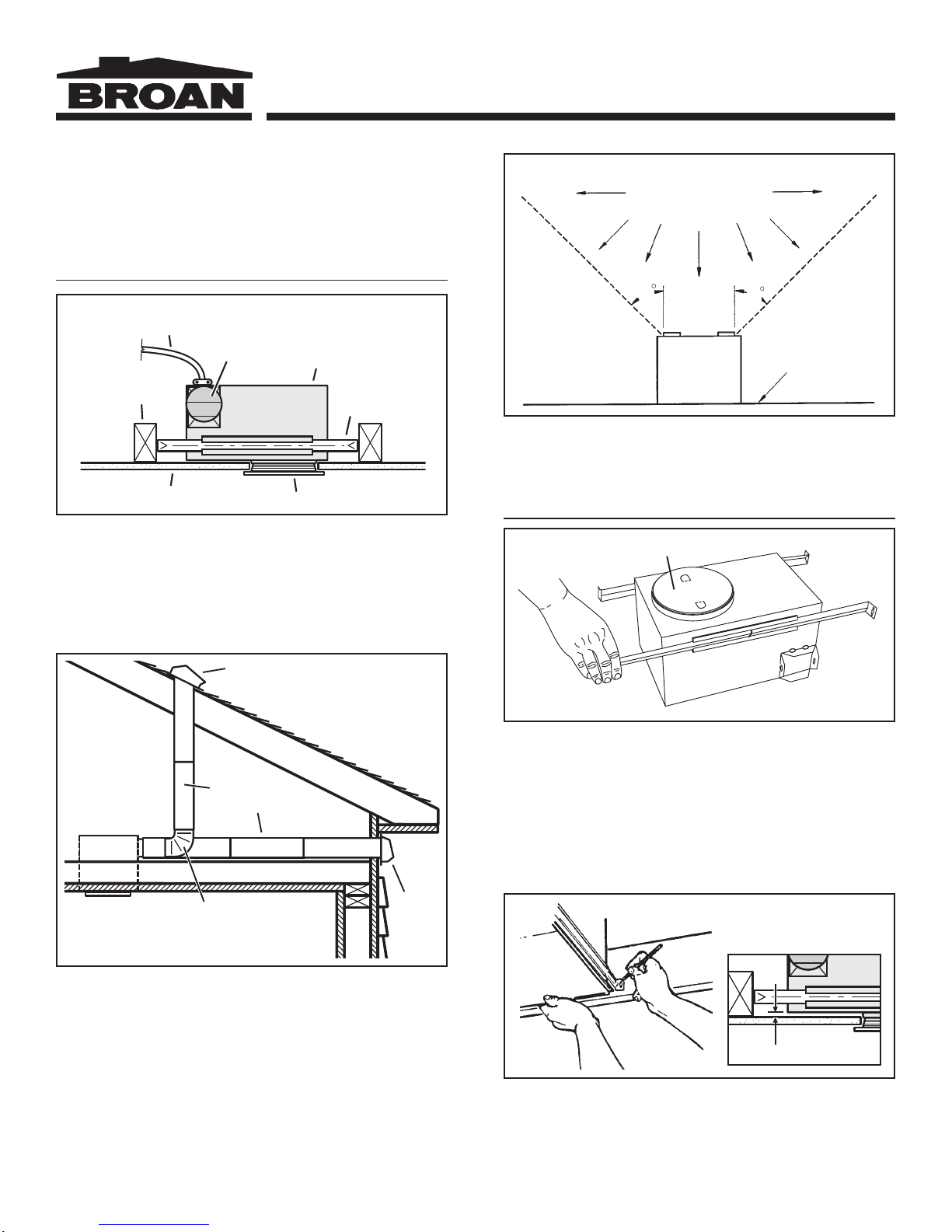
PLAN THE INSTALLATION
POWER
CABLE
CEILING
JOIST
FINISHED CEILING
The unit can be installed anywhere between ceiling joists using
mounting brackets provided.
Install in a flat ceiling only.
*
4" ROUND
DAMPER/DUCT
CONNECTOR
*
TRIM RING / BAFFLE
HOUSING
Typical Installation
MOUNTING
BRACKET
COOKING AREA
Do not install above
or inside this area
45
Cooking
Equipment
45
Floor
Do not install in a cooking area.
The unit must not be installed above or inside the cooking area
shown.
INSTALLATION
CARDBOARD PROTECTOR
4-IN. ROUND
Purchase separately
**
4-IN. ROUND
ELBOW
ROOF CAP
DUCT
**
**
**
WALL
CAP
**
Two of the most common ways to
connect ductwork to the unit.
The unit will operate most quietly and efficiently when located
where the shortest possible duct run and minimum number of
elbows will be needed.
Plan to supply the unit with proper line voltage and appropriate
power cable.
1. Install mounting brackets.
Slide the adjustable mounting brackets into the bracket channels
on the housing.
Bend the tabs on the cardboard protector and insert protector
into opening in housing.
NOTE: The cardboard protector shields the inside of the housing
from drywall spray and construction dust. Do not remove it until
after construction is completed.
1/8" GAP
2. Mark mounting location.
Position unit between joists and extend mounting brackets.
IMPORTANT: Position brackets so there will be an 1/8” gap
between bottom of housing and ceiling material. Mark the top
of keyhole slot on all four mounting brackets.
MODEL 744C
®
Page 3
VERTICAL
POWER
CABLE
CONNECTION
HORIZONT AL POWER
CABLE CONNECTION
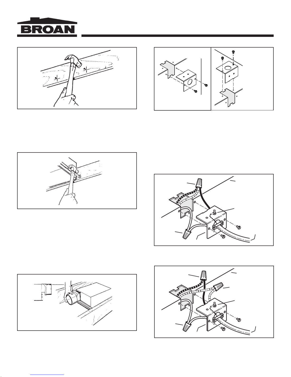
3. Pound in nails.
Remove unit temporarily, and pound nails partially into joists at
all four marked locations.
4. Hang and secure housing.
Hang unit from nails. Check to make sure that there will be a 1/
8” gap between bottom of housing and ceiling material. Pound
nails tight. For wide joist centers: A #8 x 3/8 self-tapping screw
can be used to join extended brackets together and create a
rigid mount. To ensure a noise-free mount, crimp the bracket
channels tightly around mounting brackets.
6. Choose power cable direction.
Remove wiring plate. When re-attached, the wiring plate allows
the power cable to enter unit horizontally or vertically.
7. Connect wiring.
Unit can be wired from outside of housing as shown. Use UL
approved connectors to wire per local codes.
BLUE AND RED
TO BLACK
WHITE
TO
WHITE
WIRING PLATE
TOP / BACK
OF HOUSING
GROUND TO
WIRING PLATE
2-WIRE PLUS
GROUND
POWER
CABLE
Fan and Light operated with single on/off switch
FLUSH
5. Attach damper/duct connector.
Snap the damper/duct connector onto housing. Make sure that
tabs on the connector lock in housing slots. (Top of damper/duct
connector will be flush with top of housing.)
BLUE (FAN)
TO
BLACK
WHITE
TO
WHITE
WIRING PLATE
TOP / BACK
OF HOUSING
RED (LAMP) TO RED
GROUND TO
WIRING PLATE
3-WIRE PLUS
GROUND
POWER
CABLE
Fan operated with separate on/off switch or timer.
Light operated with separate on/off switch
or dimmer switch.
 Loading...