

Broan 508N, 509N Installation Instructions Manual
Models 508N / 509N
INSTALLATION INSTRUCTIONS
Broan-NuTone Canada
Mississauga, Ontario
www.broan.ca 877-896-1119
1. All electrical connections must be in accordance with local
codes, ordinances, or Canadian Electrical Code. If you are
unfamiliar with methods of installing electrical wiring, secure
the service of a qualified electrician.
2. To avoid motor bearing damage and/or noisy and unbalanced
impellers, keep drywall spray, construction dust, etc. off power
unit.
TYPICAL INSTALLATION
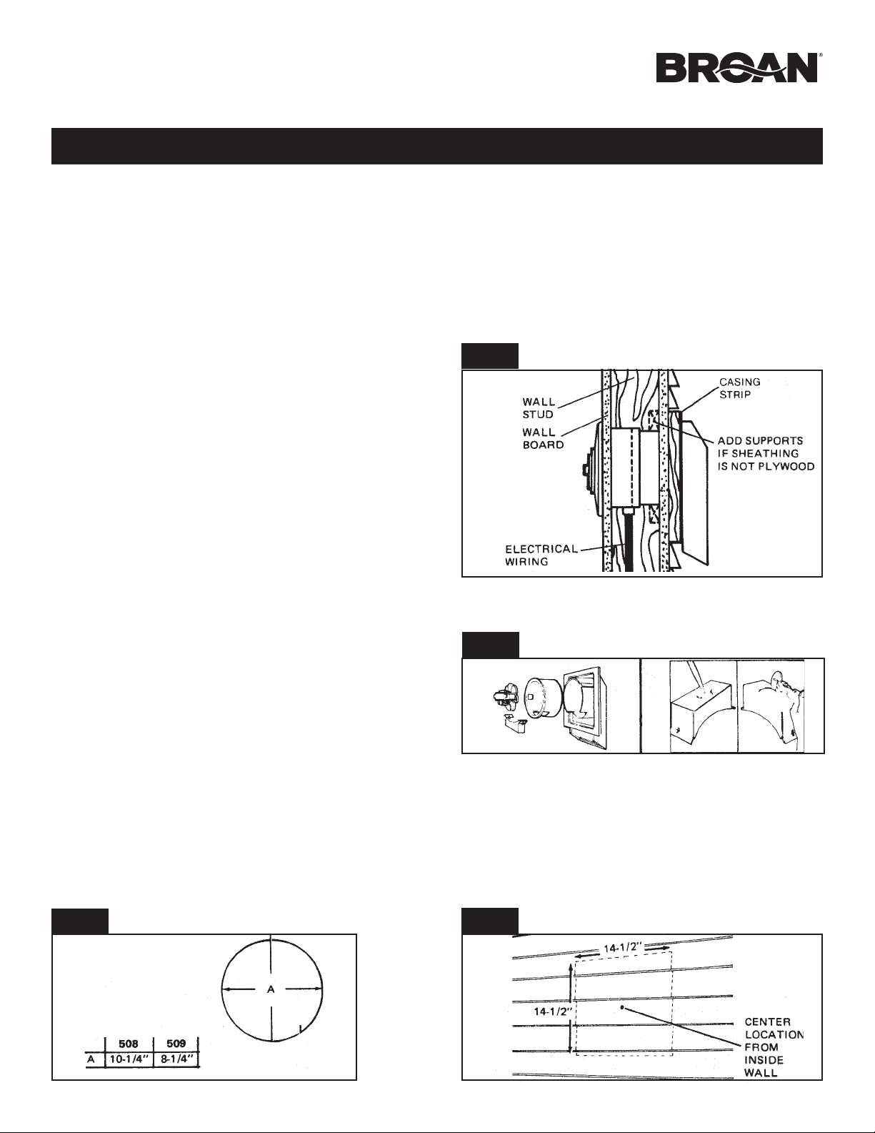
This unit mounts between walls 4½” to 9½” thick. Outside housing
flange is fastened to casing strips (1 x 2’s). See Fig. 1. If sheathing
behind siding is not wood, provide extra supports between walls
(Nailed or screwed to siding).
3. Use care when handling motor bracket assembly to prevent
damage to blade. Do not set down assembly with weight of
motor resting on the blade.
4. Disconnect electrical power supply before installing or servicing fan.
fIG. 1
FIG. 1
PREPARE FAN
1. Remove motor assembly by loosening mounting screws, rotating assembly and lifting motor assembly out of inner housing
(Figure 2).
2. Use care when handling motor bracket assembly to prevent
damage to blade. Do not set down assembly with weight of
motor resting on the blade.
3. Pull inner housing out of outer housing.
4. Remove wiring knockout from bottom of wiring box (provided
in plastic parts bag) (Figure 2).
NOTE
Remove bottom knockout ONLY!
INSTALL FAN
1. Choose fan location from inside room. Make sure that wall stud
does not run through opening. Lay out hole on wall (Figure
3).
2. Transfer center of hole to outside wall.
FIG. 3
FIG. 2
FIG. 2
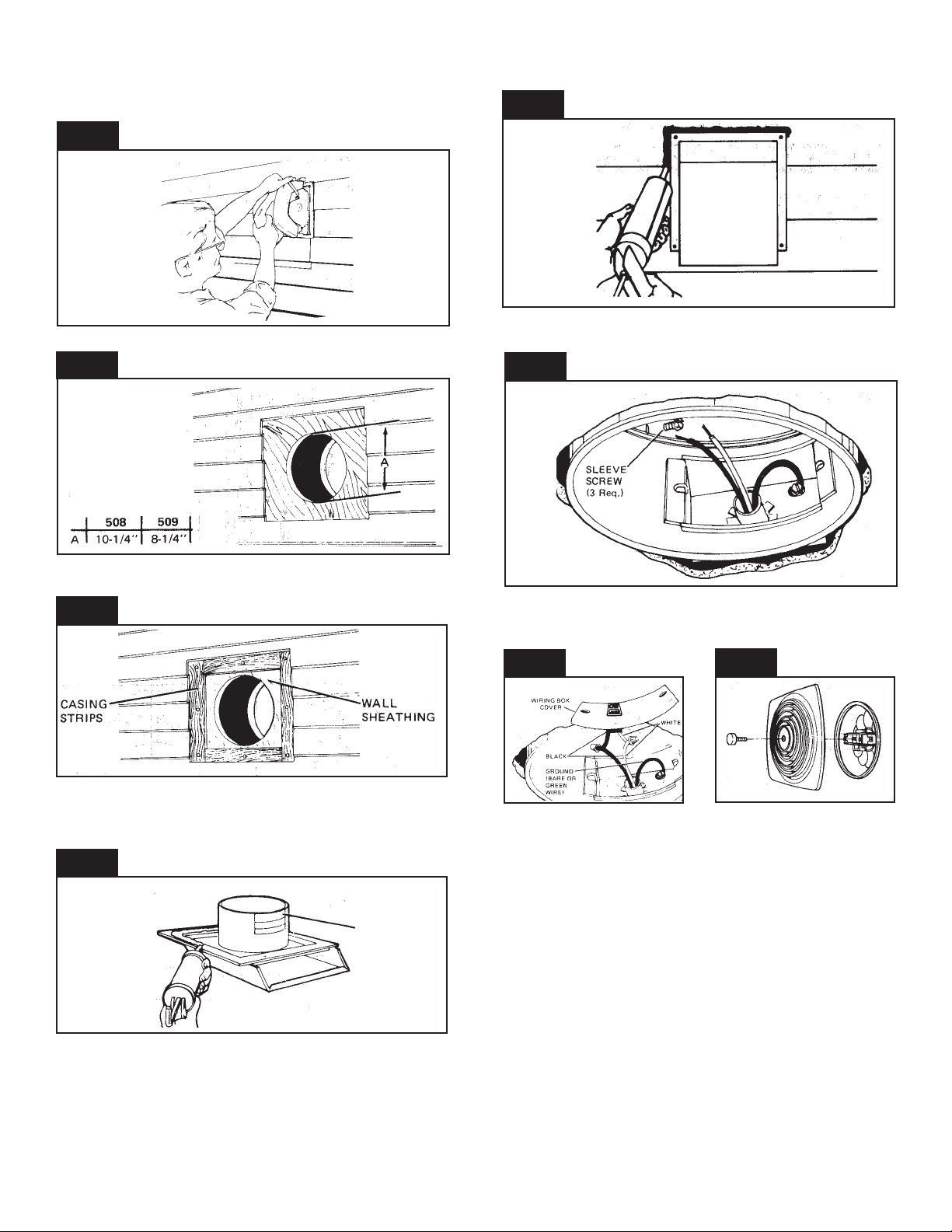
3. Cut out hole on side wall.
4. Lay out 14½” square around center location transferred from
inside room (Figure 4).
FIG. 4
INSTALL FAN (Cont’d)
5. Cut square hole in SIDING ONLY! DO NOT CUT SHEATHING
(Figure 5)! Nail down all siding ends.
FIG. 5
FIG. 9
6. Cut round hole for fan housing in sheathing (Figure 6).
FIG. 6
7. Nail or screw 1 x 2 casing strips inside square opening (Figure
7).
FIG. 7
12. Attach wiring to wiring box with proper connector for type of
wire being used. Drop box into opening in housing.
FIG. 10
13. Remove receptacle from motor plug. Snap receptacle into
wiring box cover. Make electrical connections as shown in
Figure 12.
FIG. 12
FIG. 5
FIG. 13
8. Put a large bead of caulk on the inside of flange on outer
housing (Figure 8).
9. If wall is less than 8” thick, remove one or more knockouts on
outer sleeve (Figure 8). Use inner sleeve for test fit.
FIG. 8
KNOCKOUT
PANELS
10. Insert outer housing through hole on outside wall and nail or
screw housing to casing strips. Caulk all around filler strips
and flange (Figure 9).
11. Run wiring to fan location. Pull wire through both sleeves (Figure 10). Insert inner sleeve into opening and fasten sleeves
together with three black sheet metal screws provided in plastic
bag.
30040037
14. Install wiring box cover. Use two screws provided in plastic
bag.
15.Reinstall motor assembly and plug in motor.
16. Install grille with center knob and threaded stud provided in
plastic bag. (Fig. 13)
USE AND CARE
DISCONNECT ELECTRICAL POWER SUPPLY BEFORE SERVICING FAN.
Always unplug the fan motor before servicing the fan. The motor
bearings on this fan are lifetime lubricated and will never need
oiling.
Clean the fan blade and motor every six months by removing
the grille, unplugging the motor, and gently vacuuming the fan
blade and motor.
Clean the grille in warm, soapy water. Use a mild detergent, such
as a dishwashing liquid. DO NOT USE ABRASIVE CLOTHS,
STEEL WOOL OR SCOURING POWDERS.
2
99045053A
 Loading...