

Broan 43000 Series Instructions Manual
43000 SERIES
RANGE HOOD
READ AND SAVE THESE INSTRUCTIONS
WARNING
TO REDUCE THE RISK OF FIRE, ELECTRIC SHOCK, OR INJURY TO PERSONS, OBSERVE THE FOLLOWING:
1. Use this unit only in the manner intended by the manufacturer. If you have questions, contact the manufacturer at the
address or telephone number listed in the warranty.
2. Before servicing or cleaning unit, switch power off at service
panel and lock service panel to prevent power from being
switched on accidentally. When the service disconnecting
means cannot be locked, securely fasten a prominent warning device, such as a tag, to the service panel.
3. Installation work and electrical wiring must be done by a qualified person(s) in accordance with all applicable codes and standards.
4. Sufficient air is needed for proper combustion and exhausting
of gases through the flue (chimney) of fuel burning equipment
to prevent backdrafting. Follow the heating equipment
manufacturer’s guideline and safety standards such as those
published by the National Fire Protection Association (NFPA),
and the American Society for Heating, Refrigeration and Air
Conditioning Engineers (ASHRAE), and the local code authorities.
5. When cutting or drilling into wall or ceiling, do not damage
electrical wiring and other hidden utilities.
6. Ducted fans must always be vented to the outdoors.
7. Do not use this unit with any solid-state speed control device.
8. To reduce the risk of fire, use only metal ductwork.
9. This unit must be grounded.
TO REDUCE THE RISK OF A RANGE TOP GREASE FIRE:
1. Never leave surface units unattended at high settings.
Boilovers cause smoking and greasy spillovers that may
ignite. Heat oils slowly on low or medium settings.
2. Always turn hood ON when cooking at high heat or when
cooking flaming foods.
3. Clean ventilating fans frequently. Grease should not be
allowed to accumulate on fan or filter.
4. Use proper pan size. Always use cookware appropriate for
the size of the surface element.
TO REDUCE THE RISK OF INJURY TO PERSONS IN THE
EVENT OF A RANGE TOP GREASE FIRE, OBSERVE THE
FOLLOWING:*
1. SMOTHER FLAMES with a close-fitting lid, cookie sheet, or
metal tray, then turn off the burner. BE CAREFUL TO PREVENT BURNS. If the flames do not go out immediately,
EVACUATE AND CALL THE FIRE DEPARTMENT.
2. NEVER PICK UP A FLAMING PAN - You may be burned.
3. DO NOT USE WATER, including wet dishcloths or towels - a
violent steam explosion will result.
4. Use an extinguisher ONLY if:
A. Y ou know you have a Class ABC extinguisher and you already
know how to operate it.
B. The fire is small and contained in the area where it started.
C. The fire department is being called.
D. You can fight the fire with your back to an exit.
*Based on “Kitchen Firesafety Tips” published by NFPA.
CAUTION
1. For general ventilating use only. Do not use to exhaust hazardous or explosive materials and vapors.
2. T o avoid motor bearing damage and noisy and/or unbalanced
impellers, keep drywall spray , construction dust, etc. off power
unit.
3. For best capture of cooking impurities, your range hood should
be mounted 18-25” above the cooking surface.
4. Please read specification label on product for further information and requirements.
IMPORT ANT : OBSER VE ALL GOVERNING CODES AND ORDINANCES
Your range hood has been designed to filter out smoke, odors,
and grease which rise from the cooking surface. Before you being the installation be sure that all parts and accessories are removed from carton. For best results and ease in the installation
of this range hood, read the instructions sheet to become familiar
with the step-by-step installation.
TOOLS AND MATERIALS
REQUIRED
q Drill, electric or ratchet drive
q 1/8" drill bit for drilling pilot holes
q 1-1/4" wood bit for drilling electrical wiring access hole
q One common head screwdriver for securing hood mounting
screws to the cabinet and hood sheet metal parts
q Pliers for opening knockouts
q Pencil, rule and level for marking cabinet locations
q Saber saw or keyhole saw for cutting the wall or cabinet open-
ings
q Metal snips, duct tape, duct (with elbows and transition, if nec-
essary), roof cement or caulk, and roof or wall cap, as required
q Electrical wiring and supplies of type to comply with local codes
The following materials are required only for installation on re-
cessed bottom kitchen cabinets:
q Two 1" x 2" x 12" (approximate length) wood strips (purchase
locally)
q Four 1-1/4" long flat head wood screws (purchase locally)
INSTALLER:
LEAVE THIS MANUAL WITH THE HOMEOWNER.
HOMEOWNER:
USE AND CARE INSTRUCTIONS ON
PAGE 4.
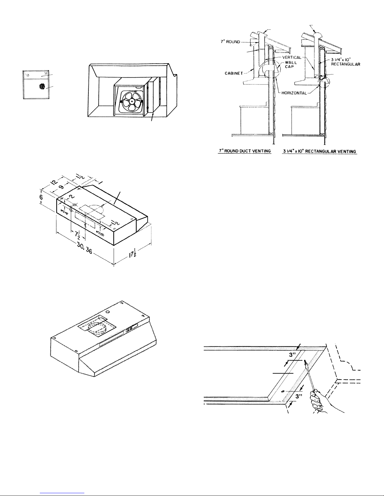
PREPARING THE HOOD
1. Unpack hood and check contents. You should receive:
1 – Filter with built-in light lens
1 – 3-1/4" x 10" damper/duct connector
1 – Installation parts bag
LIGHT LENS
ALUMINUM OR
COMBINATION
FILTER
BP87 DAMPER (NOT INCLUDED) LOCATED AT
LEAST 6" FROM HOOD
IN VERTICAL SECTION
OF DUCT
ROOF CAP
ROOF CAP
DAMPER
(INCLUDED)
REMOVE THE
HOOD DAMPER
FLAP IF IT
INTERFERES
WITH THE WALL
CAP DAMPER
2. Remove junction box cover.
JUNCTION BOX
3. Remove top or rear electrical knockout.
4. Select one of the three types of venting available:
• Non-Vented — Remove vent cover from hood front. Replace
the aluminum filter with a non-ducted filter (BP57 or R610050
- purchase separately). Go to "Preparing the Installation Location".
VENT COVER
➀➁
➂
• Rectangular Vented — 3-1/4" x 10" vertical or horizontal. Remove knockout #
venting. Install damper/duct connector over opening. Go to
"Planning Ductwork Installation".
for vertical or knockout #➂ for horizontal
➁
• Ducting directly through the wall (for range hoods mounted on
an exterior wall). Shown are two ways to duct through an outside wall. If a wall cap is used directly off the back of the hood,
special care must be taken to make sure that the damper in
the damper/duct connector on the hood and damper in the
wall cap do not interfere with each other when the hood is
operating. This could result in either inadequate air delivery or
back drafts. If this condition does exist, remove the hood
damper flap. Sometimes when using a wall cap, it is easier to
duct vertically and then use an elbow.
• Ducting straight up through roof using 3-1/4" x 10" or 7" round
duct. For single story installations.
• Ducting between ceiling joists for multi-story installations or
through soffits above cabinets where soffit connects to outside walls.
PREPARING THE
INSTALLATION LOCATION
NOTE: MOUNT HOOD SO THAT BOTTOM OF HOOD IS 18"
TO 25" ABOVE COOKING SURF ACE. TOP FRONT OF HOOD
SHOULD BE FLUSH WITH FRONT OF CABINET FRAME.
IF DISTANCE BETWEEN WALL AND FRONT OF CABINET
FRAME IS MORE THAN 12", THERE WILL BE A SPACE BETWEEN BACK OF HOOD AND WALL. THIS IS NORMAL.
OMIT STEP 1 IF HOOD WILL BE INSTALLED UNDER CABINETS WITH FLUSH BOTTOM.
• Round Vented — 7" vertical. Remove knockouts #
exposing duct collar. Go to "Planning Ductwork Installation".
PLANNING DUCTWORK
INSTALLATION
This section for vented hoods only. Non-vented hoods skip
this section and go on to "Preparing the Installation Location".
Begin planning ductwork by deciding where duct will run between
hood and outside. For best performance, use shortest possible
duct run and a minimum number of elbows. There are several
choices.
➀
and #
FILLER STRIP
➁
1. For cabinets with recessed bottoms only: Install wood filler
strips on each side of recessed area under cabinet. Use two
1" x 2" strips cut to length (use thicker strips if necessary).
Fasten strips with wood screws about 3" in from each end.
2. Measure and mark the following:
a.) Electrical wiring opening in wall or cabinet.
b.) Duct opening in wall or cabinet (vented hoods only).
2
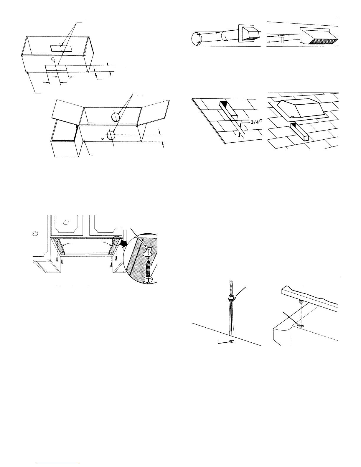
CABINET CUTOUTS
3-1/4" x 10"
RECTANGULAR
VENTING
4" (10.2 cm)
5¼"
5¼" (13.3 cm)
STARTER HOLES
1½" (3.8 cm)
CABINET
CUTOUTS
7" ROUND
VENTING
5"
STARTER HOLES
WARNING: WHEN CUTTING OR DRILLING INTO WALL OR
CABINET, BE CAREFUL NOT TO CUT EXISTING ELECTRICAL WIRING.
3. Drill 1-1/4" electrical wiring opening in wall or cabinet bottom.
4. Drill four pilot holes in corners of marked duct opening and cut
opening with saber or keyhole saw (vented hoods only).
5. Hold hood up against cabinet bottom and trace keyhole slots
onto cabinet bottom or filler strips.
KEYHOLE SLOT OUTLINE
FILLER
STRIPS
6. Screw the four supplied screws for mounting the hood into the
exact center of the narrow end of the keyhole slots marked
underneath the cabinet. Allow 3/8" of the screws to project, so
the hood can be fitted into place.
(12.7 cm)
Wall Cap Discharge: Use saber saw or keyhole saw to cut hole
slightly larger than duct size used so that duct will line up easily
with damper/duct connector on hood. Install casing strips if cap
will be installed on siding. Attach required amount of duct to wall
cap and run duct back to hood. Fasten cap to wall and caulk well.
Make sure that enough duct runs into the room so that the duct
will overlap the damper/duct connector when the hood is installed.
Roof Cap Discharge: Cut a hole in roof slightly larger than duct
size being used. Trim shingles around hole so that they will fit
snugly around hood of cap when cap is installed. Assemble the
ductwork and tape all joints. Run ductwork down to hood location. Make sure that enough duct runs into the room so that the
duct will overlap damper/duct connector when hood is put into
place. Leave 3/4" of duct projecting above roof surface on high
side.
Trim duct parallel to roof pitch and seal all around duct with roof
cement.
Carefully trim shingles and slide back of roof sheet under shingles.
Nail roof sheet to roof under shingles at top two corners and two
sides. Nail sheet directly to roof in four places at bottom.
Using roof cement, seal all nail heads and shingles which were
cut or lifted. Do not seal bottom edge of roof sheet.
INSTALLING RANGE HOOD
WARNING: TURN OFF THE PROPER CIRCUIT AT THE SERVICE ENTRANCE BEFORE WIRING THIS RANGE HOOD.
1. Check baffle for correct venting. (Non-vented or outside vented)
CONNECTOR
KEYHOLE SLOTS
INSTALLING THE DUCTWORK
THESE INSTRUCTIONS ARE FOR VENTED HOODS ONLY.
NON-VENTED HOODS SKIP THIS SECTION AND GO ON TO
"INSTALLING THE RANGE HOOD".
ST ART AT THE EXTERIOR AND RUN DUCTWORK BACK TO
THE RANGE HOOD.
FOR BEST PERFORMANCE OF YOUR RANGE HOOD, USE
THE SHORTEST POSSIBLE DUCT RUN AND A MINIMUM
NUMBER OF ELBOWS.
NEVER VENT A RANGE HOOD INTO AN ATTIC SPACE BECAUSE A BUILDUP OF GREASE WILL BECOME A FIRE HAZARD.
USE ONLY METAL DUCTWORK (DO NOT USE PLASTIC
DUCT). ASSEMBLE SECURELY SO THAT IN CASE OF A
GREASE FIRE ON THE RANGE, THE FIRE WILL BE CONTAINED INSIDE METAL DUCTWORK.
IT IS A GOOD PRACTICE TO TAPE ALL DUCT CONNECTIONS, MAKING THEM BOTH SECURE AND AIR TIGHT.
1. Follow appropriate directions below for type of ductwork you
are installing.
KNOCKOUT
OPENING
2. Run electric wiring through hole drilled in wall or cabinet. Split
wiring for 6" and install proper connector for type of wire used.
3. Position hood so that:
a.) Wiring is routed through knockout opening.
b.) Large part of keyhole slots fit over hood mounting screws.
c.) Damper/duct connector slides into ductwork (3-1/4" x 10"
vented hoods only)
4. Adjust hood so that hood front is flush with cabinet frame.
5. Tighten hood mounting screws firmly.
3
 Loading...