


Tap

Instructions for use
使用說明
BRITA Tap

2
Index
I. Congratulations Page 3
II. Ensuring you get the best from your system Page 4 – 16
III. Important notes Page 17
IV. BRITA, quality and satisfaction guaranteed Page 20
I. 恭喜您 頁碼 21
II. 確保獲得本系統最大效益 頁碼 22 – 34
III. 重要須知 頁碼 35
IV. BRITA 品質與滿意保證 頁碼 36
ENGLISH
繁體中文
Installation Video
ENGLISH 3
Your BRITA Tap, is the key to cleaner, clearer
great tasting fi ltered water
Next to hot and cold unfi ltered water,
your BRITA system offers many advantages
• You will have great tasting water at your fi ngertips
• It is economical, convenient and easy to use
• It is ideal for cooking healthy food
e.g. rice is fl uffy, naturally white and smells fantastic
your pasta will smell and taste fantastic when cooked with the
best natural ingredients and that includes fi ltered water
leaves your vegetables bursting with colour and fl avour
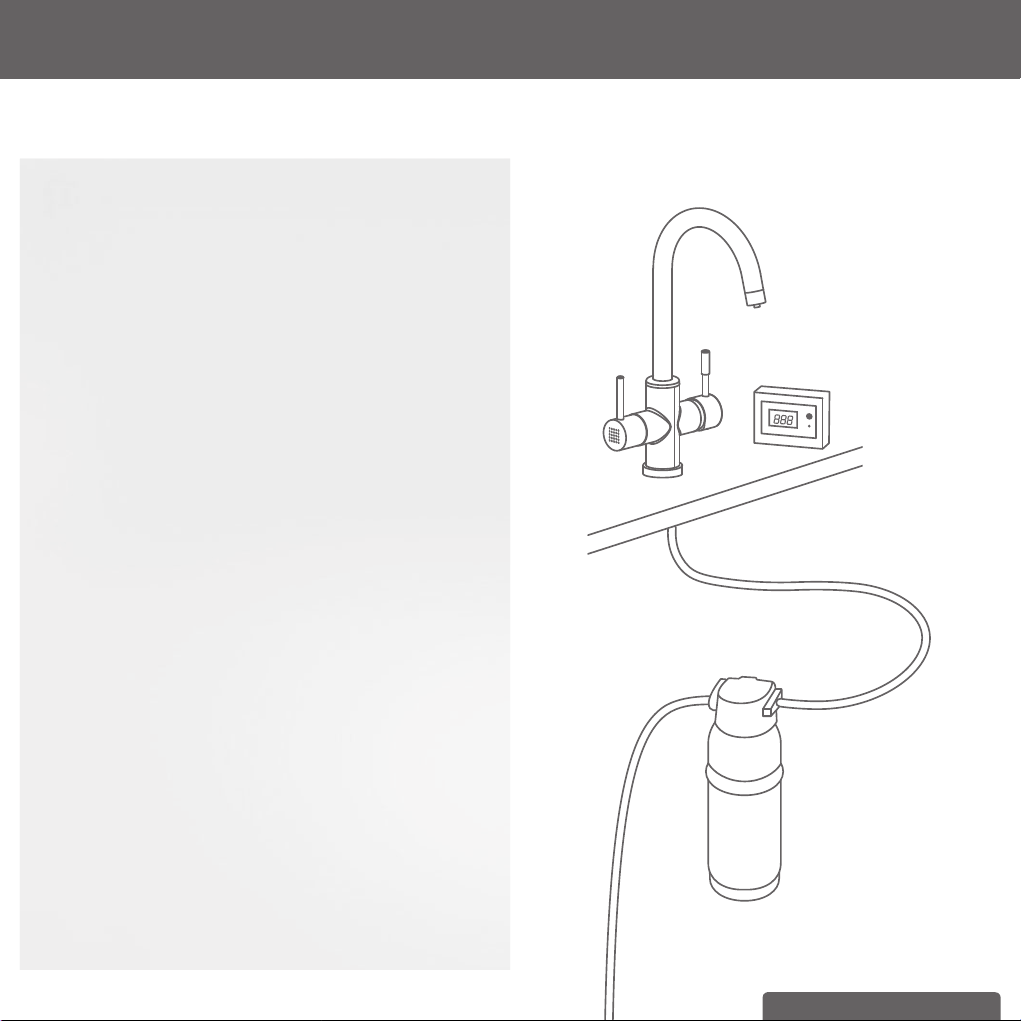
The BRITA Tap has two levers. One for BRITA fi ltered water and
the other for your regular unfi ltered hot/cold water.
The A 1000 fi lter 0.5 micron carbon block fi lter
cartridge signifi cantly reduces:
• Chlorine, unpleasant tastes and odours
• Small particles (such as rust, dust and sand)
• Organic impurities
Lifetime of the A 1000 fi lter cartridge
A 1000 fi lter cartridge life depends on local water quality.
For optimum performance and hygiene, it is recommended that
the fi lter cartridge be replaced at least six-monthly.
Your digital BRITA cartridge exchange indicator displays the
remaining number of days until the fi lter cartridge is to be replaced
and alerts you with an audible alarm after 180 days to change
the cartridge. You should check the digital display periodically. For
more information, see chapter 3.2.
I. Congratulations on your new BRITA Tap System
You are assured of BRITA quality and our commitment to our
customers.
BRITA Tap
A 1000
fi lter cartridge
BRITA cartridge
exchange indicator
4 ENGLISH
II. Ensuring you get the best from your system
1 Warranty
The BRITA Tap Systems (Models: WD 3010, WD 3020, WD 3030
and WD 3040) are warranted to be free from defects in material
and workmanship at the time of delivery. Any warranty claims will
be voided if defective installation is deemed to have contributed to
malfunction. Installation needs to take place in accordance with the
instructions and all relevant plumbing codes and standards.
The BRITA Tap Systems are designed to operate at a maximum
pressure not exceeding 0.86 MPa (860 kPa or 124 psi) and a maxi-
mum temperature of 30 °C. Ensure that pressure and temperature
do not exceed these limits.
Our goods come with guarantees that cannot be excluded under
the Australian and New Zealand Consumer Law. You are entitled to
a replacement or refund for a major failure and for compensation for
any other reasonably foreseeable loss or damage. You are also enti-
tled to have the goods repaired or replaced if the goods fail to be of
acceptable quality and the failure does not amount to a major failure.
In the event of a warranty claim, for Australia and New Zealand,
please contact BRITA Water Filter System Distributors Pty Ltd,
Level 9, 123 Epping Road North Ryde NSW 2113 Australia
email: solutions@ BRITA.com.au
Phone: Aus: 1300 557 762, NZ: 08004 BRITA
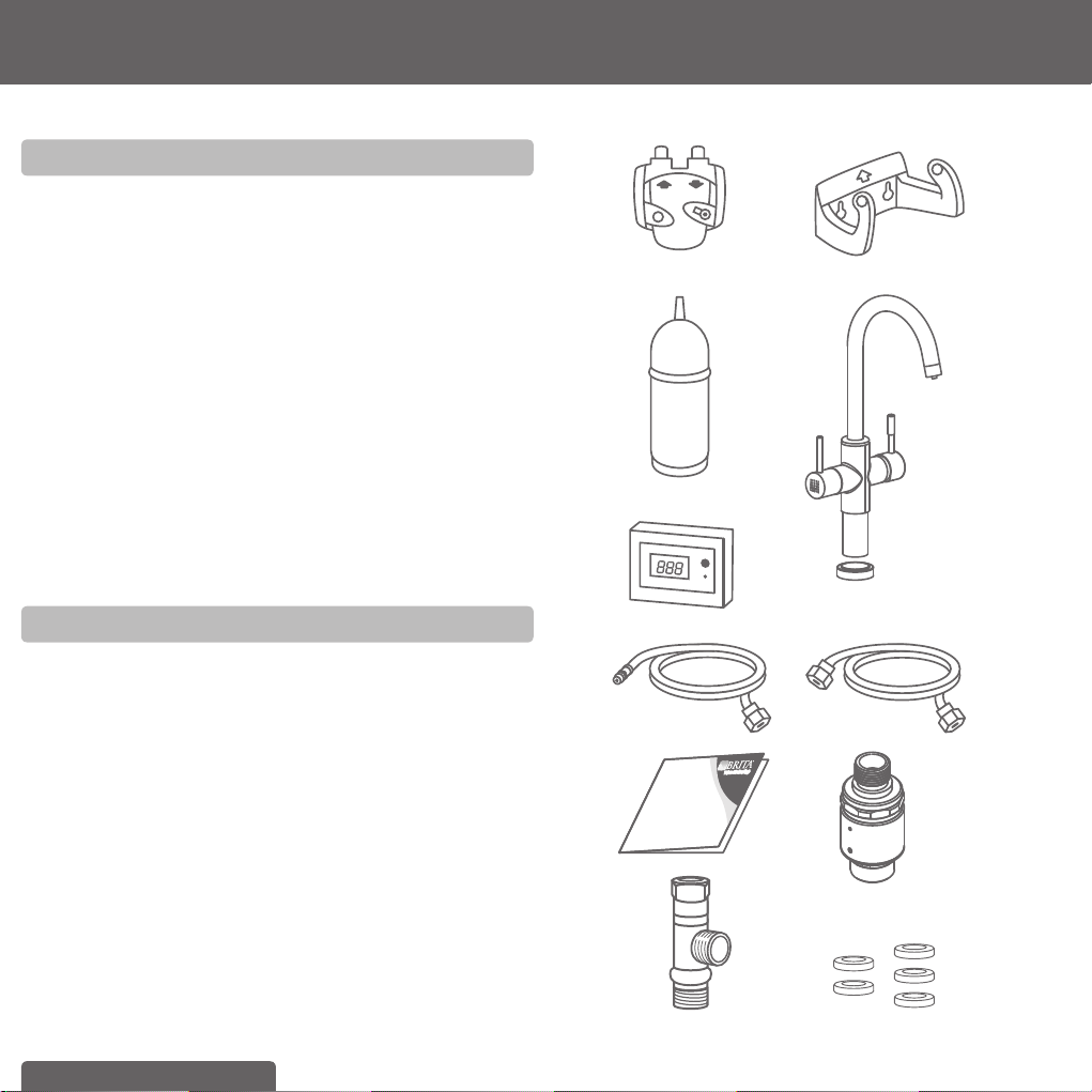
2 Contents of the BRITA Tap Starter Kit
To ensure you get the best result from your BRITA Tap System,
please follow these instructions carefully.
Your BRITA Tap Starter Kit includes the following
(see fi g. 1):
To ensure you get the best result from your BRITA Tap, please
follow these instructions carefully.
Your BRITA Tap Starter Kit includes the following (see fi g. 1):
1. Filter head with three settings (“C”, “+”, and ”++”) including
a convenient locking handle
2. Flexible wall mount bracket for fi lter head
3. A 1000 water fi lter cartridge
4. BRITA Tap (design may differ from image shown)
5. Electronic BRITA cartridge exchange indicator with digital display
and audible alarm
6. Hose (1) length = 800 mm, 1/2" nut on one side and M8
connector on the other side, 2 Hoses (2+3), length = 450 mm,
1/2" nut on one side and M8 connectors on the other side
7. Hose (4), length = 800 mm and 1/2" female nut on one end and
3/8" female nut at other end – for connection between cold
1. 2.
3. 4.
5.
6.
7.
8.
10.
(fi g. 1)
9.
11.

ENGLISH 5
water connection point and the inlet side of the fi lter head
(1/2" & 3/8" washers included in washer pack)
8. Usage instructions
9. Isolating (shut-off) valve and Pressure Limiting Valve with
back-fl ow prevention and adapter
10. T-piece
11. Washers
Recommended tools for installation: one Allen hexagonal key (4 mm),
a pipe wrench, adjustable spanner for different sizes.
Recommended for installation of the wall mount bracket: two screws
(e.g. 5 mm in size) and two wall plugs (if necessary).
Please use appropriate screws and wall plugs for the type of wall in
the under-sink compartment.
3 Installation of the BRITA Tap System
!
Installation of the fi lter system must comply with the relevant
state or local plumbing regulations and standards (AS/NZS
3500). Depending on the necessary method of connection to
the cold water supply, additional valves/adaptors/components
may be required, and the services of a licensed plumber may
be necessary. If you do not have an available connection to the
cold water supply and it is necessary to cut into the cold water
supply line, a licensed plumber is required.
Before starting, please check that you have all the components as
listed above (see fi g. 1) as well as the recommended tools.
There are 7 steps to the installation.
!
Prior to installation, read the Technical Data (chapter 8) and
the Important Information (chapter 9). (After storage and
transport below 0°C, the product must be stored in the open
original packaging for at least 24 hours at the stated ambient
temperatures (chapter 8) for operation.) The system cannot
be installed with a low pressure boiler.
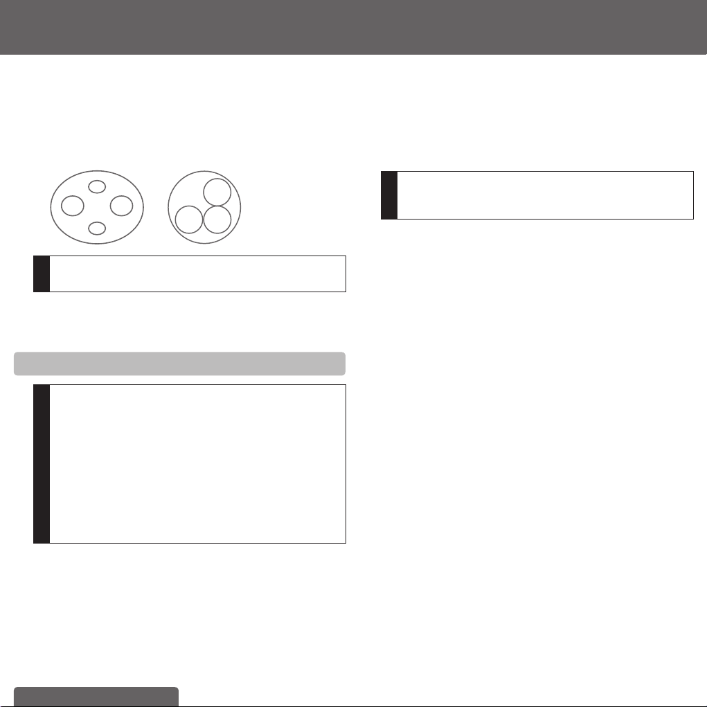
3.1 Step 1: Selecting appropriate setting on the
fi lter head
The fi lter head is set to the “++” setting by default. For use with
the supplied A 1000 fi lter cartridge you need to change the setting
in the window to “C”. Use an Allen key (hexagonal socket wrench)
and turn the hexagonal nut in the direction of the arrow in the
window until the “C” appears. Refer fi g. 2)
(fi g. 2)
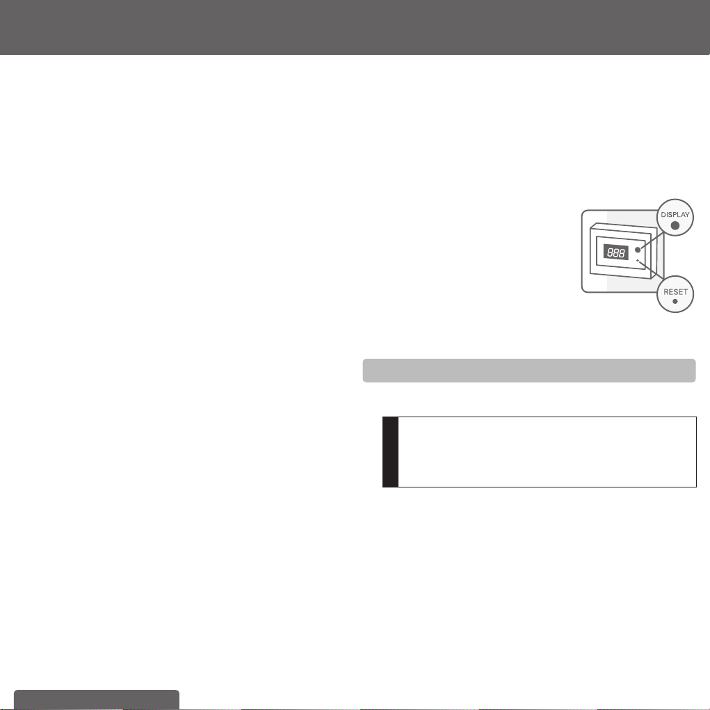
3.2 Step 2: Programming the electronic BRITA
cartridge exchange indicator
A Commissioning:
Please insert the enclosed batteries (2 x AA) into the appropriate
compartment of the electronic BRITA cartridge exchange indicator.
A long beep will sound after insertion of the batteries.
B Initial Programming:
Important: Please program the timer for 180 days.
Note: Please ensure that you activate the electronic BRITA car-
tridge exchange indicator with display during the day-time as the
alert to change the fi lter will start beeping at the exact time of day
you originally set the indicator.
Programming:
a Press the DISPLAY button briefl y to activate the display. Initially,
the default setting of 90 days fl ashes.
b Press and hold the DISPLAY button and then press the START/
RESET button briefl y. This activates the setting mode.
c Switch the display from 90 days to 180 days press the DISPLAY
button briefl y.
d Wait until the time value stops fl ashing or the DISPLAY switches
off.
e Now activate the 180-day timer by briefl y pressing DISPLAY and
then press the START/RESET button.
f A fl ashing spot in the bottom left of the display indicates that the
timer is active.
6 ENGLISH
C Reading the timer status
The display is activated by pressing the DISPLAY button briefl y
during operation. The remaining time until the exchange of the
cartridge is due is shown in days. If the time is exceeded, the time
is displayed with a minus sign.
D Audible signals
a Signal to replace the cartridge: A long signal sounds on the hour
every hour when there are less than 10 days before the end of
the programmed 180 day setting (15 double beeps). A shorter
reminder (5 double beeps) then sounds every 15 minutes until
the next signal.
b Reminder function: Press any button to deactivate the signal for
72 hours if you prefer to be reminded to replace the cartridge at
a later date.
c Battery change signal: When the batteries are depleted, a long
signal sounds (15 single beeps) followed by a short reminder
signal (5 single beeps) every 15 minutes until the next signal on
the hour.
d Switching the device off: This is only possible by removing the
batteries from the battery compartment.
E Activating the reset function when replacing the
cartridge
a Press the DISPLAY button briefl y to activate the display.
b Press and hold the START/RESET button for 5 seconds until a
long beep sounds.
c The last 180 days programmed appear in the display.
d The timer starts automatically.
F Changing the batteries
a After changing the batteries, a long beep sounds.
b After the beep, briefl y press the DISPLAY button to activate the
display.
c The remaining days since the last reset are now displayed.
(Caution: Only possible up to 16 hours after the batteries are
fully depleted. After this time, the device reverts back to the
factory setting and must be reprogrammed – see Point B).
G Installation
You can fi x the electronic BRITA cartridge exchange indicator to an
appropriate and dry place by using the supplied Velcro hook and
loop fastener. We recommend installing it under the sink in a posi-
tion of easy visibility. Avoid contact with water/splashes!
Technical data:
• Batteries: 2 AA (removable)
• Acoustic alarm: when batteries are low, or after 3 or 6 months
• To avoid loss of data, change the battery within 12 hours.
• After 16 hours without power, the appliance switches back to its
factory settings.
• The display automatically switches to stand-by mode after
10 seconds.
(fi g. 3)
3.3 Step 3: Installing the BRITA Tap
To install the BRITA Tap, fi rstly ensure you have all the components
required.
!
Please, make sure that there is enough room and access
under the sink to allow for the installation of the fi lter head
and cartridge, and to connect the two supplied hoses.
Determine the position for the convenient placement of the
exchange indicator.

ENGLISH 7
WD 3010
(fi g. 4)
1.
2.
3.
4.
5.
6.
1. BRITA Tap with 3 hoses
2. O-Ring
3. Threaded Bolt
4. Joint (Is only necessary for installa-
tion of the dispenser if you directly
mount it onto your sink. If you
mount it onto your countertop-plate,
you do not necessarily need this
part. It helps stabilizing the tap at
your sink)
5. Flat Gasket
6. Flange
7. Hex nut
WD 3020
(fi g. 5)
1.
2.
3.
4.
5.
6.
1. BRITA Tap with 3 hoses
2. O-Ring
3. Shank
4. Joint (Is only necessary for installa-
tion of the dispenser if you directly
mount it onto your sink. If you
mount it onto your countertop-plate,
you do not necessarily need this
part. It helps stabilizing the tap at
your sink)
5. Flat Gasket
6. Flange
7. Hex nut
WD 3030/ WD 3040
(fi g. 6)
1.
2.
3.
4.
5.
6.
7.
1. BRITA Tap (design may differ) with
3 hoses
2. Shank
3. Base
4. Joint (Is only necessary for installa-
tion of the dispenser if you directly
mount it onto your sink. If you
mount it onto your countertop-plate,
you do not necessarily need this
part. It helps stabilizing the tap at
your sink)
5. Flat Gasket
6. Flange
7. Hex nut
First of all, dismount your existing kitchen tap.
A a) Turn off the cold and hot water supplies
b) Please make sure you release any pressure by opening all
levers.
!
No water should run through the existing kitchen tap.
c) Unscrew the existing hoses from the cold and hot water
supply.
!
We recommend placing a suitable container under the water
supply as there will be water left in the hoses which will run
down when you unscrew them.
d) Unscrew your kitchen tap – there is no standard mounting but
in general a pipe wrench will help you to dismount it.
e) Pull out both your kitchen tap and the hoses. You’re now
ready to install the BRITA Tap (see fi g. 4).
First of all, screw the shank (2) into the BRITA Tap (1).
Screw the hoses into the dispenser (see fi g. 7).
7.
7.
8 ENGLISH
Screw the M8 connector of the hose with the blue stripe into the
hole C.
Screw the M8 connector of the hose with the red stripe into the
hole H.
Screw the M8 connector of the 800 mm hose into the hole B.
C
B
H
(fi g. 7)
WD 3010
WD 3020/ WD 3030/ WD 3040
C
BH
!
Ensure the connections are screwed tight, but avoid over-
tightening.
Then place the base (3) over the hole and fi x the BRITA Tap (1) in
position using the supplied counter plate (4), the washer (5), the
locking ring (6) and the hexagon nut (7).
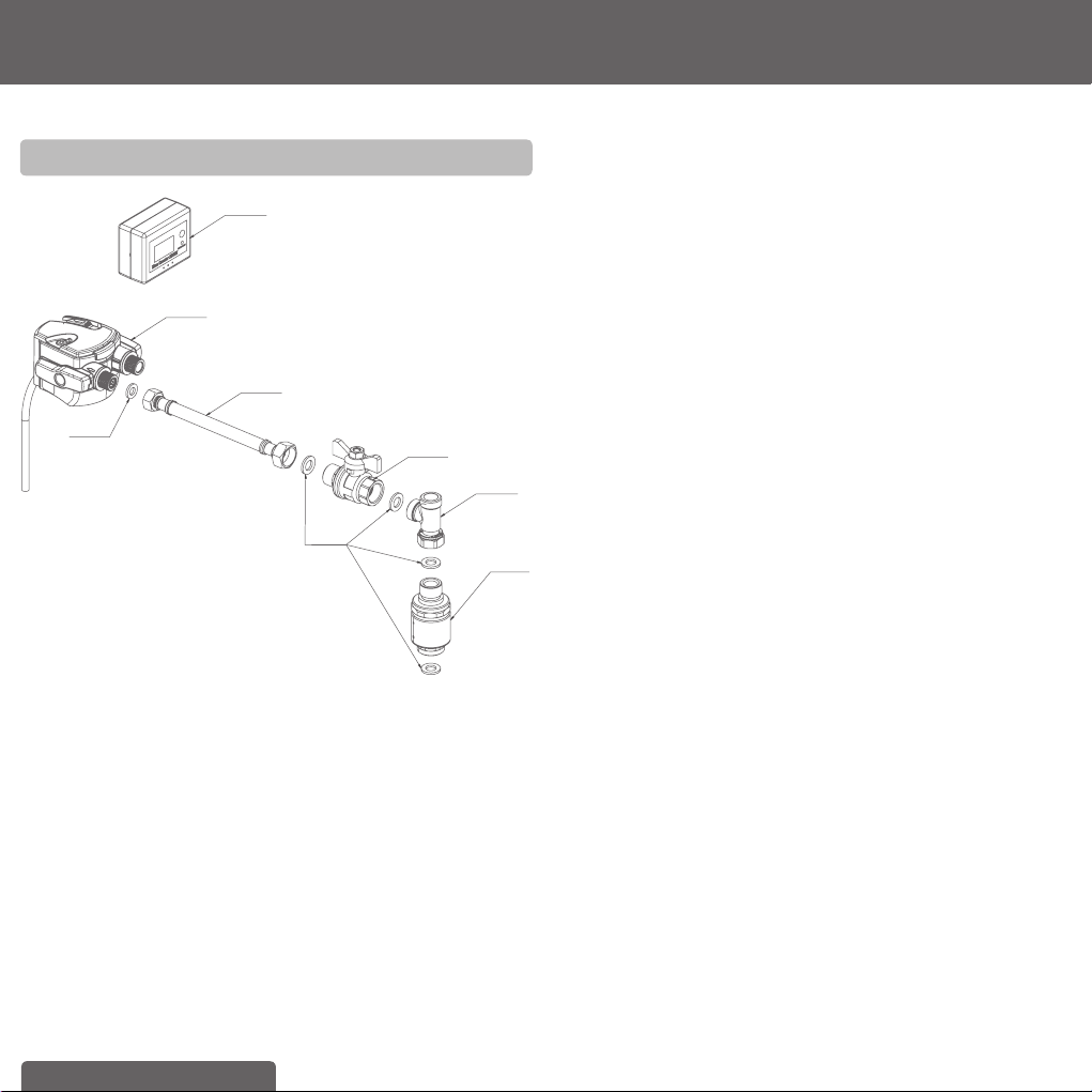
3.4 Step 4: Attaching the hoses
!
The supplied hose for connection to the cold water supply
requires the availability of an already installed ½" isolation
or angle valve). Before installation, please ensure you have
such a free ½" isolation or angle valve and that it is work-
ing properly (closeable to 100 %). If not, please contact
a licensed plumber. In accordance with regulations, the
stopcock) which is included in your kit must be installed at
the point of connection to the water supply before the fi lter
system intake hose. Behind the stopcock or isolation valve
a pressure limited valve must always be installed to ensure
the right function of the cartridge. Plumbing tape should
be used on all threads in this sub-assembly and tested to
ensure there are no leaks.
We recommend that you fi rst arrange all parts you need in front of
you.
Recommended tools for installation: one Allen key and an adjust-
able spanner.
Recommended for installation of the wall mount bracket: two
screws (e.g. 5 mm in size suited to the mounting surface) and two
wall plugs (if necessary).
Please follow the diagram below (see fi g. 7) and perform the steps
in the right order.
A Connect supplied T-piece on your cold water supply
a) Insert one 1/2" washer into the female nut of the supplied
T-piece.
b) Connect this end of the t-piece to your cold water supply.
!
If you do have an additional free 1/2" cold water supply for
the BRITA Tap in your kitchen, you do not need to install the
supplied T-piece.
B Connect the hose with the blue stripe to one side of the T-piece
or free ½” cold water supply using washer supplied.
C Take the hose with two 1/2" connectors. Insert the 1/2" washers
into the respective female threads of the two hose ends. Con-
nect one end with the free side of the T-Piece.
D Now connect the other end to the fi lter head inlet. This is labelled
“IN” and marked with an arrow. Make sure that the washers are
seated correctly!
E Connect the 800 mm hose to the “OUT” (connection point on
fi lter head) which labelled with an out arrow.
F Connect the hose with the red stripe with your hot water supply
G Make sure all connections are tightened properly. Avoid over
tightening.

ENGLISH 9
(fi g. 8)
Hot water
supply
Cold water
supply
!
The max. tightening torque for the 1/2" connections may
not exceed 14 Nm! Only hose connections with wash-
ers may be used – hoses with conical screw connections
damage the connections of the fi lter head and invalidate
any warranty claims.
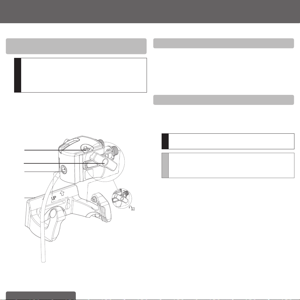
3.5 Step 5: Inserting the fi lter cartridge (see fi g. 9)
A Remove the protective strap (1).
B Insert the fi lter cartridge (4) vertically into the fi lter head (2).
C Turn the locking handle (3) until you it clicks.
(fi g. 9)
A.
B.
3.
2.
1.
4.
5.
!
The fi lter cartridge can only be inserted when the locking
handle (3) is open.
Make sure that the fi lter cartridge is positioned correctly and
all o-rings are correctly positioned.
10 ENGLISH
3.6 Step 6: Install fi lter-head wall-mount bracket
(see fi g. 10)
!
During assembly, note the installation dimensions, bending
radii of the hoses and dimensions of the accessories. The
system can be operated with the fi lter cartridge in either
vertical or horizontal positions. Using the mounting bracket,
it should be installed only vertically, with the “UP” arrow on
the bracket correctly positioned.
A Attach the space-saving wall mount bracket (1) in place using two
matching screws and use two wall plugs (not supplied), depend-
ing on the type of wall. Position it in an accessible place to allow
for 90° pivoting of the head for easy exchange of the fi lter.
B Engage the fi lter head (2) in the wall mount (1) using the notches
(4) on the sides of the fi lter head to connect to the arms of the
bracket.
1.
2.
3.
4.
(fi g. 10)
3.7 Step 7: Commissioning
Before use, make sure that you have followed all the steps
correctly and all the parts are fi tted. Place a suitable container
under the cartridge to catch any leakages.
A Turn on the cold and hot water supplies and check the system
carefully for any leaks.
B Open the BRITA Tap and allow water to run until the fi ltered
water runs clear and without any bubbles (at least 1 litre).
4 Replacing the fi lter cartridge
To ensure optimum performance and for hygienic reasons, the
fi lter cartridge is be replaced six months after fi rst use, irrespective
of usage. Monitor the display on the cartridge indicator at regular
intervals and be alert for the audible alarm signal that will sound at
the end of the set 180 days.
!
Read the Operating and Safety Information (chapter 9) prior
to exchange of fi lter.
NOTE
The fi lter cartridge can be pivoted by 90° in the wall mount
bracket for easy removal. When the locking handle is open,
the water supply to the cartridge is interrupted, without the
need to turn off the isolating valve.
Replacing the A 1000 fi lter cartridge (see fi g. 9):
A Open the locking handle (3).
B To release the pressure in the system, fi rst place a suitable
container under the fl ush hose to catch any water, then press the
fl ush button (5).
C Remove the exhausted fi lter cartridge (4) from the fi lter head (2).
D Insert the new fi lter cartridge (see chapter 3.5 Step 5).
E Close the locking handle (3). Open the BRITA Tap and allow
water to run until the fi ltered water runs clear and without any
bubbles (at least 1 litre).
ENGLISH 11
5 Resetting the electronic cartridge
exchange indicator
A Press the DISPLAY button briefl y to activate the display.
B Press and hold the START/RESET button for 5 seconds until a
long beep sounds.
C The previously set “180” days appears in the display.
D The timer starts automatically.
6 Maintenance
Regularly check the fi lter system for leaks. Regularly check the
hoses for kinks. Kinked hoses must be replaced.
The expected in- service life of the complete fi lter system is fi ve
years.
!
Prior to exchanging the fi lter system, read the Technical Data
(chapter 7) and the Operating and Safety Information
(chapter 9).
Regularly clean the outside of the fi lter system with a soft, damp
cloth.
!
Do not use any abrasive chemicals, cleaning solutions or
astringent cleaning agents.
7 Troubleshooting
A No water fl ow
Cause: Water intake closed.
Troubleshooting: Open the water intake at the upstream shut-off
valve or by closing the locking handle (3) on the
fi lter head (2).
B No or low water fl ow in spite of open water intake
Cause: Mains pressure too low.
Troubleshooting: Check mains pressure. If the fault continues,
check the fi lter system and fi lter cartridge and
replace if necessary.
Cause: Filter head not mounted in direction of water
fl ow.
Troubleshooting: Dismantle fi lter head and install in direction of
water fl ow (chapter 3.4).
C Leak
Cause: Screwed connections not fi tted correctly.
Troubleshooting: Check mains pressure. Check all screwed
connections in accordance with chapter 3.4.
D Incorrect display or incorrect settings on the electronic
cartridge exchange indicator with display
Cause: Buttons pressed in wrong order or wrong
buttons pressed.
Troubleshooting: Press and hold the RESET button for 8 seconds.
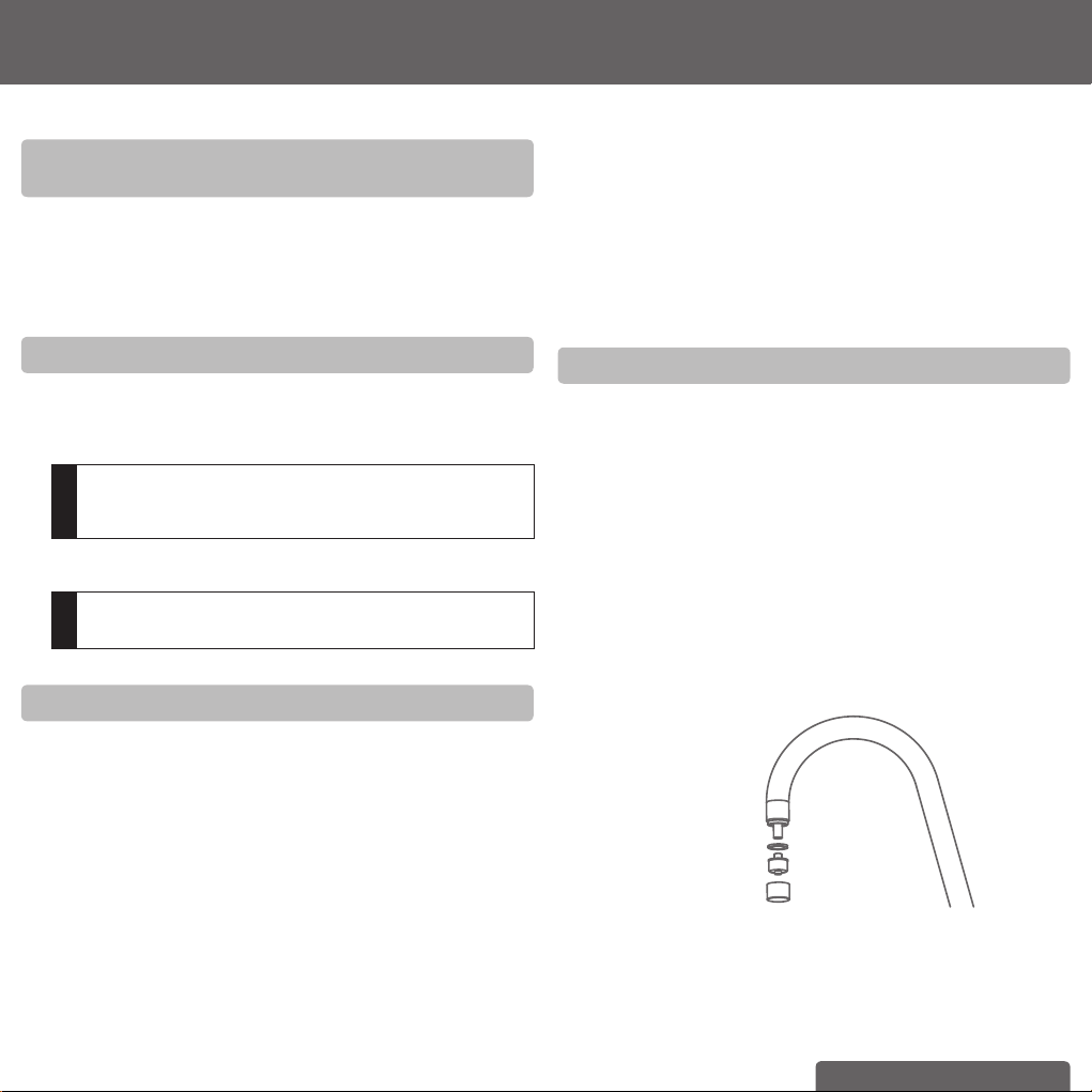
For models WD 3030 and WD 3040 only
These models have an aerator with two integrated outlets. The
Inner one is for BRITA fi ltered water, the outer area for hot and cold
water. As with every tap aerator, there can be lime scale build up
in the outer area. Therefore it is recommended to clean the aerator
on a regular basis. For cleaning: Unscrew the cap on the end of the
dispenser’s neck. The aerator is connected to a silicon hose. Detach
it carefully and clean the aerator (e.g. with vinegar). After cleaning
connect the long, thin part on the back of the aerator carefully with
the silicon hose. Place the cap over the aerator and screw it tight.
Make sure that the washer in the cap is seated correctly. When
installed correctly there should not be any leaks whilst running hot,
cold or BRITA fi ltered water.
If you want to replace the aerator with a new one, you can order
it from BRITA. You can fi nd the contact details for your BRITA
customer service team next to your country code on the back of this
booklet.
(fi g. 11)
12 ENGLISH
Spare Part Name
1004674
1012909
1004710
1008502
1004713
1004715
1014490
101449
2
(fi g. 12)
Article No. Spare Part Name
1004715 Gasket On Line 3/8" 2 mm CE + AU
1004713 Gasket On Line 1/2" 2 mm CE + AU
1004710 Hose On Line 1/2" IT - 3/8" IT AU
1012909 Filter Head G3/8" BRITA Tap spare part
1004674 BRITA cartridge exchange indicator
1014490 Isolation Valve Spare Part AU
1014492 Pressure Limting Valve Spare Part AU
1008502 T-piece 1/2"
 Loading...