


Brinkmann 810-8905-S, 810-7405-S, 810-8500-S, 810-8530-S, 810-8555-S User Manual
...NOTICE TO
PROFESSIONAL INSTALLER:
LEAVE THESE INSTRUCTIONS WITH
THE GRILL OWNER FOR FUTURE
REFERENCE.
AVISO PARA EL
INSTALADOR:
ENTREGUE ESTAS
INSTRUCCIONES AL PROPIETARIO
DE LA PARRILLA PARA
REFERENCIA FUTURA.
Universal Natural Gas Conversion Kit
Equipo Universal de Conversión a Gas Natural
PROFESSIONAL INSTALLATION MANUAL MANUAL DE INSTALACIÓN PROFESIONAL
CONVERTS THE FOLLOWING CHARMGLOW GRILLS FROM PROPANE TO NATURAL GAS: MODEL NUMBERS 810-7405-S, 810-8500-S, 810-8530-S, 810-8532-S, 810-8550-S, 810-8552-S, 810-8555-S, 810-8750-S, 810-8752-S, 810-8905-S, 810-8907-S, 810-9520-S, AND 810-9590-S.
ALSO CONVERTS MODELS 810-8640-S AND 810-8650-S. PROFESSIONAL INSTALLATION MANUALS FOR THESE MODELS ARE INCLUDED WITH THE GRILLS. IF YOU DO NOT HAVE THE PROFESSIONAL INSTALLATION MANUAL, PLEASE VISIT WWW.GRILLPARTSONLINE.COM OR CALL (800) 527-0717.
CONVIERTE LAS SIGUIENTES PARRILLAS CHARMGLOW DE PROPANO A GAS NATURAL: NÚMEROS DE MODELO 810-7405-S, 810-8500-S,
810-8530-S, 810-8532-S, 810-8550-S, 810-8552-S, 810-8555-S, 810-8750-S, 810-8752-S, 810-8905-S, 810-8907-S, 810-9520-S, Y 810-9590-S
TAMBIÉN CONVIERTE LOS MODELOS 810-8640-S Y 810-8650-S. LOS MANUALES PROFESIONALES DE INSTALACIÓN PARA ESTOS MODELOS SE INCLUYEN CON LAS PARRILLAS. SI USTED NO TIENE EL MANUAL PROFESIONAL DE INSTALACIÓN, VISITE POR FAVOR WWW.GRILLPARTSONLINE.COM O LA LLAMADA (800) 527-0717.
ASSEMBLY AND OPERATING INSTRUCTIONS
INSTRUCCIONES DE ARMADO Y OPERACIÓN
SAVE THIS MANUAL FOR FUTURE REFERENCE
GUARDE ESTE MANUAL PARA REFERENCIA FUTURA
 WARNING
HAZARDOUS EXPLOSION MAY RESULT IF THESE WARNINGS AND INSTRUCTIONS ARE IGNORED. READ AND FOLLOW ALL WARNINGS AND INSTRUCTIONS IN THIS MANUAL TO AVOID PERSONAL INJURY, INCLUDING DEATH OR PROPERTY DAMAGE.
 ADVERTENCIA
SE PUEDE PRODUCIR UNA EXPLOSIÓN PELIGROSA SI SE HACE CASO OMISO A ESTAS ADVERTENCIAS E INSTRUCCIONES. LEA Y SIGA TODAS LAS ADVERTENCIAS E INSTRUCCIONES EN ESTE MANUAL PARA EVITAR LESIONES PERSONALES, INCLUSO LA MUERTE, O LOS DAÑOS MATERIALES.

 IMPORTANT SAFETY WARNINGS
WE WANT YOU TO USE YOUR CONVERSION KIT FOR YOUR GRILL AS SAFELY AS POSSIBLE. THE PURPOSE OF THIS SAFETY ALERT SYMBOL  IS TO ATTRACT THE ATTENTION TO POSSIBLE HAZARDS AS THE GRILL IS CONVERTED AND USED AS A NATURAL GAS GRILL. WHEN YOU SEE THE SAFETY ALERT SYMBOL
PAY CLOSE ATTENTION TO THE INFORMATION WHICH FOLLOWS!
 READ ALL SAFETY WARNINGS AND INSTRUCTIONS CAREFULLY
BEFORE CONVERTING AND OPERATING YOUR GRILL.
 DANGER
IF YOU SMELL GAS:
1.Shut off gas to the appliance.
2.Extinguish any open flame.
3.Open Lid.
4.If odor continues, keep away from appliance and immediately call your gas supplier or your fire department.
 WARNING
1.Do not store or use gasoline or other flammable liquids or vapors in the vicinity of this or any other appliance.
2.An LP cylinder not connected for use shall not be stored in the vicinity of this or any other appliance.
Failure to follow the instructions as written, or installation by other than a trained professional, will void all manufacturer warranties.
Installer Company or Service Name:________________________________________________
Technician Name:____________________________________Installation Date: ____________
 WARNING
This conversion kit shall be installed by a professional service technician in accordance with the manufacturer's instructions as specified by the codes and requirements of the authority having jurisdiction. The information in these instructions must be followed to minimize the risk of fire or explosion or to prevent property damage, personal injury or death. The qualified service agency performing this conversion assumes responsibility for the proper conversion of the appliance of this kit.
IMPORTANT: Fill out product record information below.
Model Number: ____________________________________
Serial Number:_____________________________________Date Purchased: ____________
1

TABLE OF CONTENTS
General Warnings. . . . . . . . . . . . . . . . . . . . . . . . . . . . . . . . . . . . . . . . . . . . . . . . . . . . . . . . . 3
Assembly Instructions . . . . . . . . . . . . . . . . . . . . . . . . . . . . . . . . . . . . . . . . . . . . . . . . . . . 4-28
Conversion Instructions 810-8905-S, 810-8907-S . . . . . . . . . . . . . . . . . . . . . . . . . . . . . . . . . . . . . . . . . . . . . . . . . . . . . 5
Conversion Instructions 810-8750-S, 810-8752-S . . . . . . . . . . . . . . . . . . . . . . . . . . . . . . . . . . . . . . . . . . . . . . . . . . . . . 9
Conversion Instructions 810-8550-S, 810-8552-S & 810-8555-S . . . . . . . . . . . . . . . . . . . . . . . . . . . . . . . . . . . . . . . . . 13
Conversion Instructions 810-8530-S, 810-8532-S . . . . . . . . . . . . . . . . . . . . . . . . . . . . . . . . . . . . . . . . . . . . . . . . . . . . 17
Conversion Instructions 810-8500-S . . . . . . . . . . . . . . . . . . . . . . . . . . . . . . . . . . . . . . . . . . . . . . . . . . . . . . . . . . . . . . . 22
Conversion Instructions 810-7405-S . . . . . . . . . . . . . . . . . . . . . . . . . . . . . . . . . . . . . . . . . . . . . . . . . . . . . . . . . . . . . . . 25
Conversion Instructions 810-9590-S . . . . . . . . . . . . . . . . . . . . . . . . . . . . . . . . . . . . . . . . . . . . . . . . . . . . . . . . . . . . . . . 28
Conversion Instructions 810-9520-S . . . . . . . . . . . . . . . . . . . . . . . . . . . . . . . . . . . . . . . . . . . . . . . . . . . . . . . . . . . . . . . 31
Connecting to Natural Gas Source. . . . . . . . . . . . . . . . . . . . . . . . . . . . . . . . . . . . . . . . . . . 34 Leak Testing . . . . . . . . . . . . . . . . . . . . . . . . . . . . . . . . . . . . . . . . . . . . . . . . . . . . . . . . . 35-37
Pre-start Check List . . . . . . . . . . . . . . . . . . . . . . . . . . . . . . . . . . . . . . . . . . . . . . . . . . . . . . 37
Lighting Instructions . . . . . . . . . . . . . . . . . . . . . . . . . . . . . . . . . . . . . . . . . . . . . . . . . . . . . . 38
Operating Grill and Helpful Hints. . . . . . . . . . . . . . . . . . . . . . . . . . . . . . . . . . . . . . . . . . 39-43
Warranty Information . . . . . . . . . . . . . . . . . . . . . . . . . . . . . . . . . . . . . . . . . . . . . . Back Cover
DANGER: Indicates an imminently hazardous situation which, if not avoided, will result in death or serious injury.
WARNING: Be alert to the possibility of serious bodily injury if the instructions are not followed. Be sure to read and carefully follow all of the messages.
CAUTION: Indicates a potentially hazardous situation which, if not avoided, may result in minor or moderate injury.
FOR GRILL WARRANTY REPLACEMENT PARTS, PLEASE VISIT US AT:
www.grillpartsonline.com
 WARNING
•FOR OUTDOOR USE ONLY. DO NOT operate indoors or in an enclosed area such as a garage, shed or breezeway.
•Use your grill OUTDOORS in a well ventilated space away from dwellings or other buildings to prevent dangers associated with gas accumulation and toxic vapors. We recommend your grill be situated at least 10 feet (3.1 m) from buildings.
•Maintain a minimum clearance of 36 inches (91 cm) between all sides of grill and walls or other combustible material. DO NOT use grill under overhead unprotected combustible construction.
•DO NOT use or install this grill in or on a recreational vehicle and/or boat.
INSTALLATION INFORMATION:
The installation of this appliance must be in accordance with:
All applicable local codes, or in the absence of local codes, either:
•National Fuel Gas Code ANSI Z223.1 NFPA 54
•Natural Gas and Propane Installation Code: CAN/CGA B149.1
•Natural Gas Installation Code: CAN/CGA B149.1 (Canada)
This kit converts your grill for natural gas use at 7 inch water column supply pressure. To check your pressure contact your local natural gas company. If the supply pressure is different than 7 inch, contact a professional service technician for assistance. Not for use with LP gas.
2

 DANGER
Connection should be made by a professional service technician. Supply the technician with a copy of these instructions. Incorrect connection can result in a gas leak with possibility of fire.
GENERAL WARNINGS
 WARNING
•Never use liquid propane gas in a unit designed for natural gas.
•Never use charcoal or wood briquette in a gas grill. Flavoring chips must be contained in a metal smoking box to contain ash and prevent fires.
•Leak test all connections before first use, even if grill was purchased fully assembled.
•Never check for leaks using a match or open flame.
 CAUTION: Strong odors, colds, sinus congestion, etc. may prevent the detection of natural gas. Use caution and common sense when testing for leaks.
•Always keep your gas grill free and clear of gasoline, lighter fluid, paint thinner, or other flammable vapors and liquids or combustible materials.
•Always check the grill prior to each use as indicated in the "Pre-Start Check List" section of this manual.
•Only use the specific orifice designated for your grill model. Always double check the millimeter size on the side of the orifice tip prior to installation. Use of any other orifice could lead to personal injury, property damage and void your grill warranty.
•DO NOT use back rotisserie burner when main burners are in use.
•DO NOT obstruct the flow of combustion or ventilation air.
•Never place more than 15 pounds on the side burner. DO NOT lean on the side burner shelf.
•Keep children and pets away from hot grill. DO NOT allow children to use or play near this grill.
•DO NOT leave the grill unattended while in use.
•DO NOT allow the gas hose to come in contact with hot surfaces.
•DO NOT allow grease from drain hole to fall on hose.
•Keep any electrical supply cords away from water or heated surfaces.
•Keep a fire extinguisher on hand acceptable for use with gas products. Refer to your local authority to determine proper size and type.
•For household use only. DO NOT use this grill for anything other than its intended purpose.
•DO NOT use while under the influence of drugs or alcohol.
• Grill is hot when in use. To avoid burns:
•DO NOT attempt to move the grill.
•Lock the wheels so the unit does not accidentally move.
•Wear protective gloves or oven mitts.
•DO NOT touch any hot grill surfaces.
•DO NOT wear loose clothing or allow hair to come in contact with grill.
 USE CAUTION AND COMMON SENSE WHEN OPERATING YOUR GAS GRILL.
FAILURE TO ADHERE TO THE SAFETY WARNINGS AND GUIDELINES IN THIS MANUAL COULD RESULT IN SEVERE BODILY INJURY OR PROPERTY DAMAGE.
SAVE THIS MANUAL FOR FUTURE REFERENCE.
3
ASSEMBLY INSTRUCTIONS
 YOU MUST BE A PROFESSIONAL SERVICE TECHNICIAN TO CONVERT THIS GRILL. READ ALL SAFETY WARNINGS & ASSEMBLY INSTRUCTIONS CAREFULLY BEFORE ASSEMBLING OR OPERATING THE CONVERTED GRILL.
The following tools are required to assemble the Conversion Kit:
• Phillips Head Screwdriver |
• |
Adjustable Wrench |
• 3/4” Wrench |
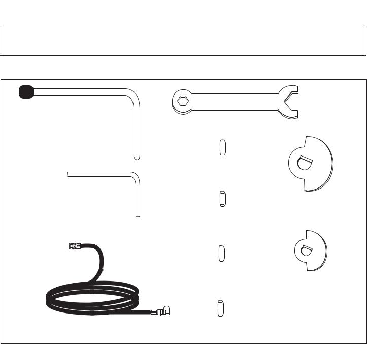
PARTS CONTENTS
Gas Orifice Tool
Large Wrench
1.51mm


8905/8907 Rotisserie Burner
1.51mm Valve Orifice x 1 Pc
(BLUE)
Small Wrench
1.35mm


8750/8752 Side Burner
1.35mm Valve Orifice x 2 Pc
(RED)
1.25mm


8905/8907 SIde Burner
1.25mm Valve Orifice x 2 Pc
(GREEN)
1.32mm


8530/8532/8550/8552/8555
10’ Natural Gas Hose Rotisserie Burner 1.32mm Valve Orifice x 1 Pc (YELLOW)
L
Large
Stop Plate
x 6 Pcs.
S
Small
Stop Plate
x 1 Pc.
(Proof of purchase will be required.)
Inspect contents of the box to ensure all parts are included and undamaged.
FOR GRILL WARRANTY REPLACEMENT PARTS, PLEASE VISIT US AT: www.grillpartsonline.com
4

CONVERSION
INSTRUCTIONS
810-8905-S & 810-8907-S
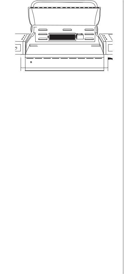
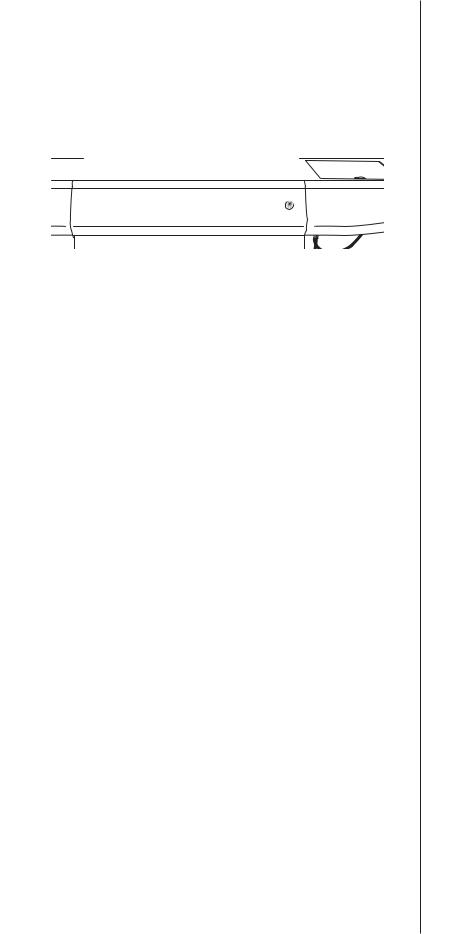
Back Panel Exit |
|
Gas Manifold |
|
|
|
|
|
|
 CAUTION: Some parts may contain sharp edges. Wear protective gloves if necessary.
 WARNING: Only use the specific orifice designated for your grill model. Always double check the millimeter size on the side of the orifice tip prior to installation. Use of any other orifice could lead to personal injury, property damage and void your grill warranty.
Note: Make sure all control knobs are in the off position, LP tank valve is closed and tank is disconnected from regulator and removed from grill.
Step 1
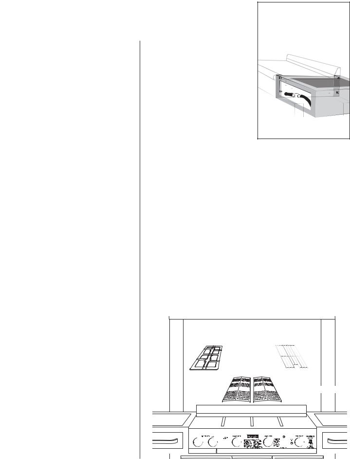
Hold the gas manifold connection with an adjustable wrench and use a 3/4” wrench to undo LP hose connection from gas manifold.
Step 2
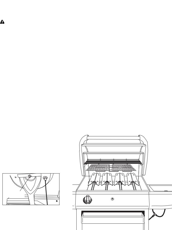
Attach 10’ hose to gas manifold. Tighten connection carefully using two wrenches. Take the end of the 10’ hose and place it through the cart back panel exit.
Step 3
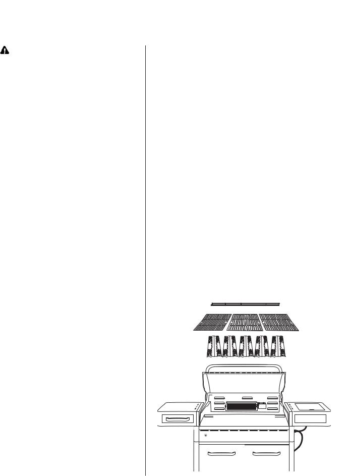
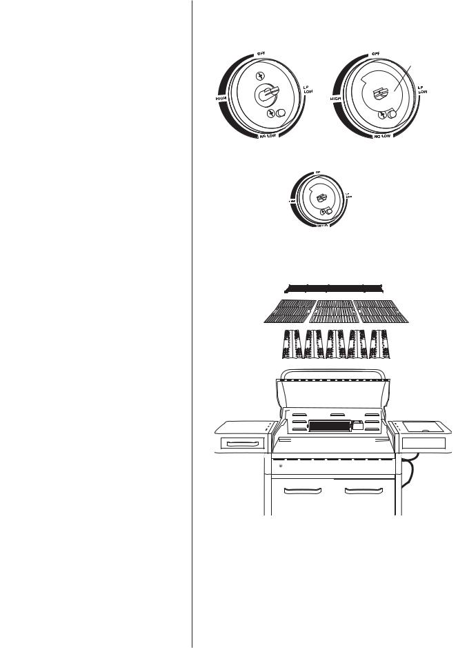
Open hood and remove warming rack, cooking grills and heat shields. Set aside for later use.
10’ Natural Gas Hose
Warming Rack
Cooking Grills
Heat Shields
5
|
Step 4 |
|
Remove two screws from each |
Wood Chip Drawer |
burner "foot" using a screwdriver. |
|
Remove wood chip drawer to get |
|
access to the wood chip burner. |
|
Remove one screw from the wood |
|
chip burner. Carefully lift each burner |
|
up and away from valve openings. |
|
Set aside for later use. |
Side View
|
|
Step 5 |
|
|
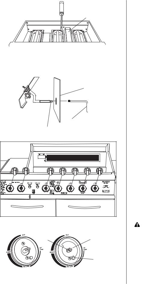
Using the gas orifice tool, remove |
|
Fire Box Front Panel |
the LP brass orifice from the tip of |
|
each gas valve assembly. Repeat |
|
|
|
this step for all main burner and |
|
|
wood chip burner valves in your |
|
|
grill. |
|
|
Note: All orifices of the grill, except |
|
Gas Orifice Tool |
rotisserie, are double orifices |
|
type (LP gas and natural gas). |
|
LP Gas Orifice |
|
|
|
You only remove the LP gas |
|
|
|
orifice tip. |
|
|
Step 6 |
|
|
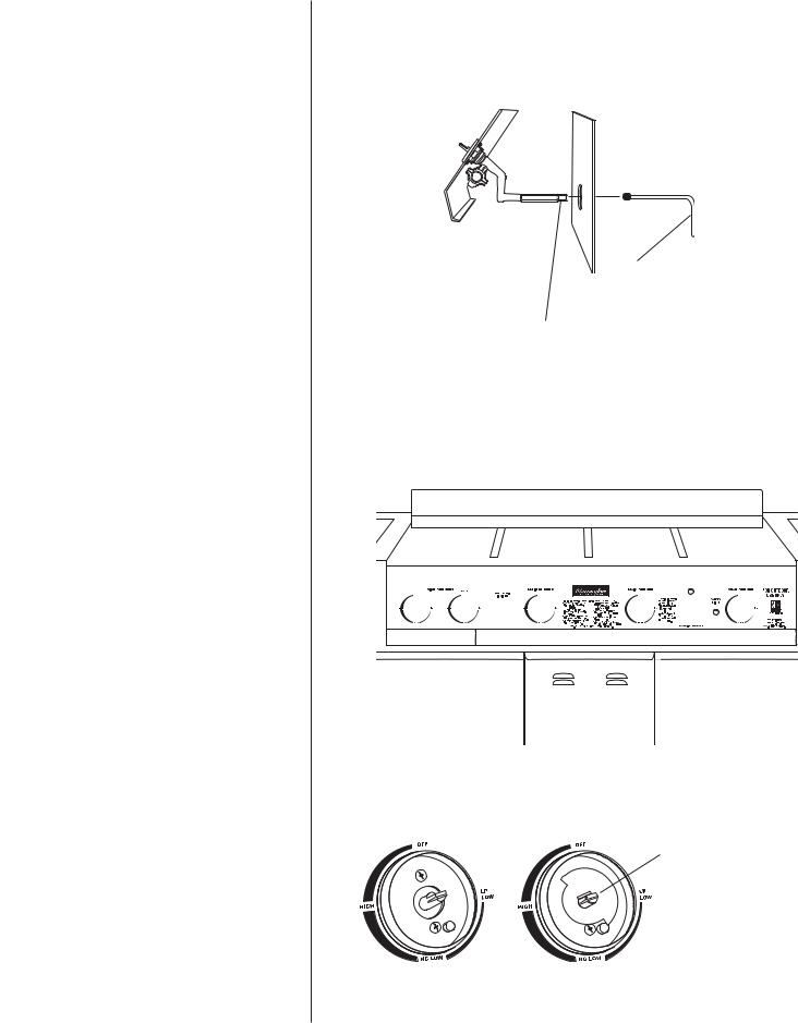
Remove all the control knobs from the |
|
|
control panel and set aside for later |
|
|
Step 7 |
|
|
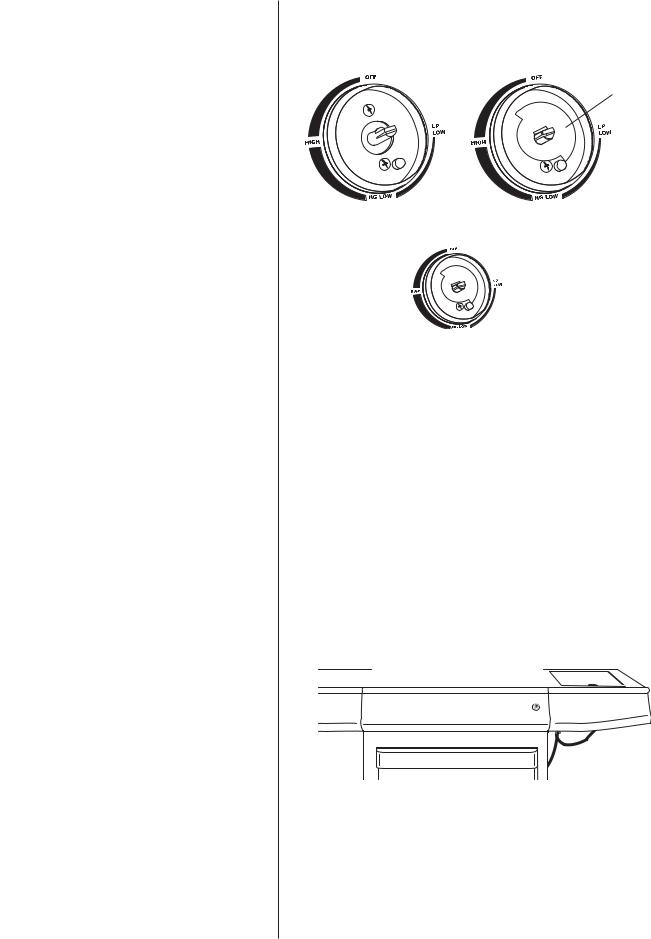
Figure 1 shows valve stem and bezel |
|
|
with both screws. Place stop plate over |
|
|
valve stem as shown in Figure 2. Verify |
|
|
the tab and the stamped letter on the |
|
|
stop plates face out. Replace control |
|
|
knobs when finished. |
|
|
WARNING: We recommend and |
|
|
request that you do not remove the |
Tab |
Stop Plate |
control panel in order to access the |
|
valve tips. If you choose to remove |
|
|
L |
|
|
the control panel, you must replace |
|
|
|
|
|
|
the control panel bezels exactly as |
|
Stop Pin |
illustrated in Figure 2. Failure to |
|
replace the bezels as illustrated |
|
|
|
|
Figure 1 |
Figure 2 |
could lead to personal injury and/or |
property damage. |
6
810-8905-S & 810-8907-S SIDE BURNERS
 CAUTION: Only use specified natural gas orifice for your grill.
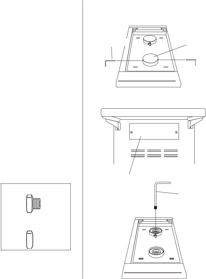
Step 8
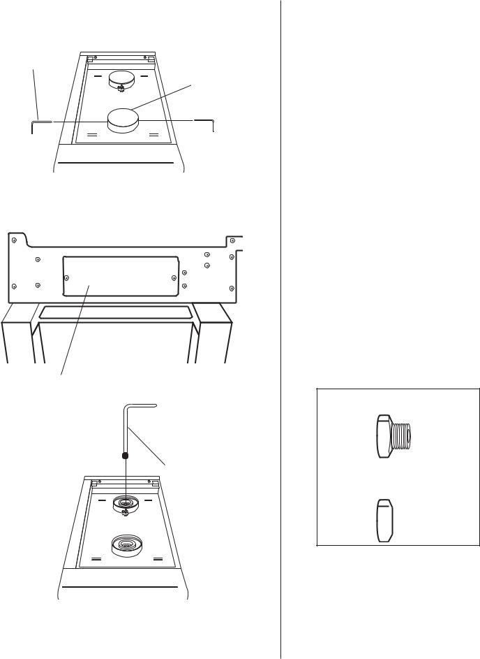
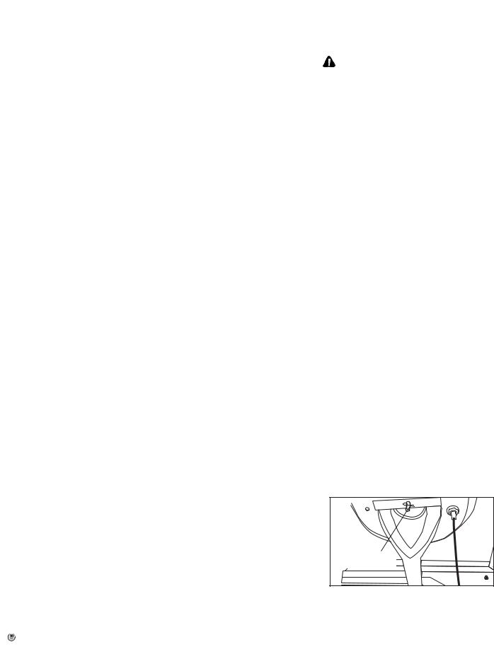
Remove the side burner brass cap by using the small wrench to unscrew the two small screws.
Step 9
Remove access panel on left side of grill for better view of gas orifice.
Step 10
Use the gas orifice tool to remove LP brass orifice from the hole on the top of side burner.
Step 11
Using gas orifice tool, install 1.25mm (GREEN) natural gas orifice. Be careful not to cross thread natural gas orifice.
Existing Side Burner LP
Gas Orifice
Replacement Side Burner
Natural Gas Orifice (identified by number)
Side Burner 1.25mm (GREEN)
1.25mm


Step 12
Replace the side burner brass cap to the burner.
Small Wrench
Brass Cap
Access Panel
Gas Orifice Tool
7
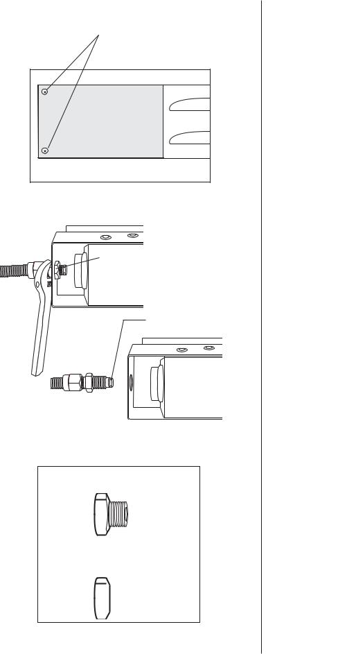
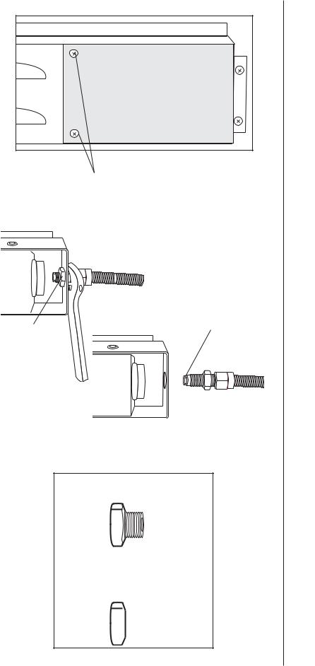
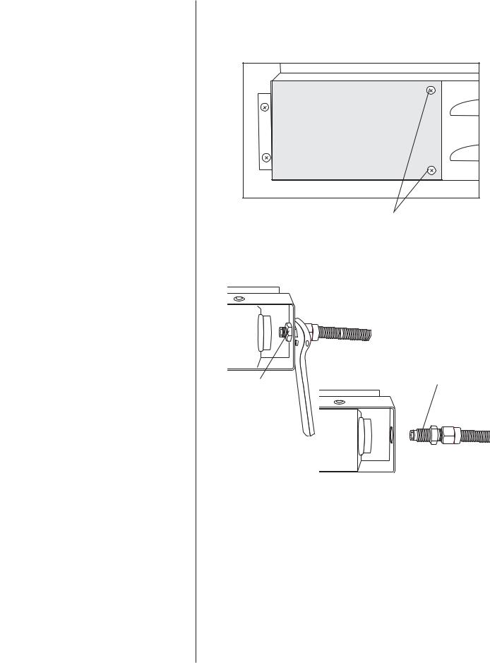
Cover Bolts
Retaining Nut
Brass Orifice
Existing Rotisserie LP
Gas Orifice
Replacement Rotisserie
Natural Gas Orifice (identified by number)
Rotisserie Burner 1.51mm (BLUE)
1.51mm


810-8905-S & 810-8907-S ROTISSERIE BURNERS
 CAUTION: Only use specified natural gas orifice for your grill.
Note: |
It is helpful to keep the screws with the |
|
components as they are removed for |
|
ease of reassembly. |
Step 13
Remove rotisserie cover bolts and remove rotisserie cover to gain access to the rotisserie LP gas orifice on back side of grill.
Step 14
Using an adjustable wrench to hold the gas line secure, use the open end wrench provided to loosen the gas line retaining nut. With the rotisserie gas supply line detached from the housing, use two wrenches to remove the LP brass orifice from the gas supply line. Replace the LP gas brass orifice with the proper natural gas orifice. (1.51mm BLUE)
Note: Bending the hose could damage the supply line.
Step 15
Reattach gas supply line to the rotisserie housing by securing with the retaining nut removed in Step 14.
Note: Leave the back panel off until the end of conversion and all gas leak testing has been completed.
Step 16
Re-install the rotisserie cover using the nuts and bolts that were set aside in Step 13.
Step 17
Carefully replace each burner, making sure burner openings slide over valve nozzles. Screw each burner "foot" down using screwdriver and screws that were set aside in Step 4.
Step 18
Replace warming rack, cooking grills, heat shields and grease trays.
Note: Follow directions in the leak testing section of this manual before using this grill.
8
CONVERSION
INSTRUCTIONS
810-8750-S & 810-8752-S
 CAUTION: Some parts may contain sharp edges. Wear protective gloves if necessary.
 WARNING: Only use the specific orifice designated for your grill model. Always double check the millimeter size on the side of the orifice tip prior to installation. Use of any other orifice could lead to personal injury, property damage and void your grill warranty.
Note: Make sure all control knobs are in the off position, LP tank valve is closed and tank is disconnected from regulator and removed from grill.
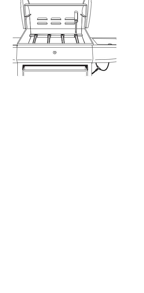
Step 1
Pull right accessory drawer out and remove. Set drawer aside until you are ready to re-insert drawer at the end of Step 2.
Step 2
Hold the gas manifold connection with an adjustable wrench and use a 3/4” wrench to undo hose connection from gas manifold. Attach 10’ hose to gas manifold. Tighten connection carefully using two wrenches.
Step 3
Open covers and remove cooking grills and heat shields. Set aside for later use.
Right
Accessory
Drawer
10’ Natural Gas Hose
Cooking Grills


 Heat Shields
9
Main Burner
Sear Burner
Note: Step 4 only applies to model 810-8750-S.
Step 4
Remove screw from each burner "foot" using a screwdriver. Carefully lift each burner up and away from valve openings. Set aside for later use.
10
 CAUTION: Some parts may
contain sharp edges. Wear Side View protective gloves if necessary.
Fire Box Front Panel
Step 5
Using the one of the gas orifice tool provided remove the LP brass orifice from the tip of each gas valve assembly.
Wrench
Note: All orifices of the grill, except
rotisserie, are double orifices
type (LP gas and natural gas). LP Gas Orifice You only remove the LP gas
orifice tip.
Step 6 |
|
|
Remove all the control knobs from the |
|
|
control panel and set aside for later |
|
|
use. |
|
|
Step 7 |
|
|
Figure 1 shows valve stem and bezel |
|
|
with both screws. Place stop plate over |
|
|
valve stem as shown in Figure 2. Verify |
|
|
the tab and the stamped letter on the |
|
|
stop plates face out. Replace control |
|
|
knobs when finished. |
|
|
WARNING: We recommend and |
|
|
request that you do not remove the |
|
|
control panel in order to access the |
|
Tab |
valve tips. If you choose to remove |
|
|
the control panel, you must replace |
|
L |
the control panel bezels exactly as |
|
|
|
|
|
illustrated in Figure 2. Failure to |
|
|
replace the bezels as illustrated |
|
Stop Pin |
could lead to personal injury and/or |
|
|
property damage. |
Figure 1 |
Figure 2 |
|
11
Small Wrench
Brass Cap
Access Panel
Gas Orifice Tool
810-8750-S & 810-8752-S SIDE BURNERS
 CAUTION: Only use specified natural gas orifice for your grill.
Step 8
Remove the left side shelf by unscrewing the four bolts.
Step 9
Remove the side burner brass cap by using the small wrench to unscrew the two small screws.
Step 10
Remove access panel on left side of grill for better view of gas orifice.
Step 11
Use the gas orifice tool to remove LP brass orifice from the hole on the top of side burner.
Step 12
Using gas orifice tool, install 1.35mm (RED) natural gas orifice. Be careful not to cross thread natural gas orifice.
Existing Side Burner LP
Gas Orifice
Replacement Side Burner
Natural Gas Orifice (identified by number) Side Burner 1.35mm (RED)
1.35mm


Step 13
Replace the side burner brass cap to the burner.
12
CONVERSION
INSTRUCTIONS 810-8550-S, 810-8552-S & 810-8555-S
CAUTION: Some parts may contain sharp edges. Wear protective gloves if necessary.
WARNING: Only use the specific orifice designated for your grill model. Always double check the millimeter size on the side of the orifice tip prior to installation. Use of any other orifice could lead to personal injury, property damage and void your grill warranty.
Note: Make sure all control knobs are in the off position, LP tank valve is closed and tank is disconnected from regulator and removed from grill.
Step 1
Using an adjustable wrench to hold the gas manifold connection secure, use a 3/4” wrench to loosen the hose connection nut. Replace existing LP hose/regulator assembly with natural gas 10’ hose assembly. Tighten both connections carefully using two wrenches.
Step 2
Remove cotter pin from side burner "foot". Carefully lift side burner up and away from valve nozzle. Set aside for later use.
Cotter Pin
Step 3
Open hood and remove warming rack, cooking grills and heat shields. Set aside for later use.
Gas Manifold Nut
10’ Natural Gas Hose
 Warming Rack
Cooking Grills
Heat Shields
13
Side View
Firebox Front Panel
LP Gas Orifice
Gas Orifice Tool
Step 4
Remove screw from each burner "foot" using a screwdriver. Carefully lift each burner up and away from valve openings. Set aside for later use.
Step 5
Use the gas orifice tool to remove the LP brass orifice from main burner valves through the hole on the firebox front panel. Repeat this step for all main, side and rotisserie burner valves in your grill. The side burner valve orifice is under the side shelf.
Note: All orifices of the grill, except rotisserie, are double orifices type (LP gas and natural gas).You only remove the LP gas orifice tip.
 CAUTION: Some parts may contain sharp edges. Wear protective gloves if necessary.
Step 6
Remove all the control knobs from the control panel and set aside for later use.
14
Step 7
Figure 1 shows valve stem and bezel with the control knob removed. Take five large stop plates from the component card and place them over the main and side burner valve stems as illustrated (Figure 2). Take the small stop plate from the component card and place it over the rotisserie burner valve stem (Figure 3). Verify the tab and the stamped letter on the stop plates face out. Replace control knobs when finished.
 WARNING: We recommend and request that you do not remove the control panel in order to access the valve tips. If you choose to remove the control panel, you must replace the control panel bezels exactly as illustrated in Figure 2. Failure to replace the bezels as illustrated could lead to personal injury and/or property damage.
Step 8
Carefully replace each burner, making sure burner openings slide over valve nozzles. Screw each main burner "foot" down using screwdriver and screws that were set aside in Step 4. Replace cotter pin in side burner “foot” that were set aside in Step 2.
Step 9
Replace warming rack, cooking grills, heat shields and grease tray.
Note: Follow directions in the leak testing section of this manual before using this grill.
Stop Plate
Tab
L
 Stop Pin
Figure 1 |
Figure 2 |
Tab |
Stop Plate |
S |
|
|
|
|
Stop Pin |
|
Figure 3 |
 Warming Rack
Cooking Grills
Heat Shields
15
Cover Bolts
Brass Orifice
Retaining Nut
Existing Rotisserie LP
Gas Orifice
Replacement Rotisserie
Natural Gas Orifice (identified by number)
Rotisserie Burner 1.32mm (YELLOW)
1.32mm


810-8550-S, 810-8552-S & 810-8555-S ROTISSERIE BURNERS
 CAUTION: Only use specified natural gas orifice for your grill.
Note: It is helpful to keep the screws with the components as they are removed for ease of reassembly.
Step 10
Remove the two screws of panel to gain access to the rotisserie LP valve on back side of grill. Set aside for later use.
Step 11
Using an adjustable wrench to hold the gas line secure, use the open end wrench provided to loosen the gas line retaining nut. With the rotisserie gas supply line detached from the housing, use two wrenches to remove the LP brass orifice from the gas supply line. Replace the LP gas brass orifice with the proper natural gas orifice. (1.32mm YELLOW)
Note: Bending the hose could damage the supply line.
Step 12
Reattach gas supply line to the rotisserie housing by securing with the retaining nut removed in Step 11.
Note: Leave the back panel off until the end of conversion and all gas leak testing has been completed.
Step 13
Re-install rotisserie cover using the bolts that were set aside in Step 10.
16
CONVERSION
INSTRUCTIONS
810-8530-S & 810-8532-S
CAUTION: Some parts may contain sharp edges. Wear protective gloves if necessary.
 WARNING: Only use the specific orifice designated for your grill model. Always double check the millimeter size on the side of the orifice tip prior to installation. Use of any other orifice could lead to personal injury, property damage and void your grill warranty.
Note: Make sure all control knobs are in the off position, LP tank valve is closed and tank is disconnected from regulator and removed from grill.
Step 1
Using an adjustable wrench to hold the gas manifold connection secure, use a 3/4” wrench to loosen the hose connection nut. Replace existing LP hose/regulator assembly with natural gas 10’ hose assembly. Tighten the connection carefully using two wrenches.
Step 2
Remove cotter pin from side burner "foot". Carefully lift side burner up and away from valve nozzle. Set aside for later use.
Cotter Pin |
Step 3
Open hood and remove warming rack, cooking grills and heat shields. Set aside for later use.
Gas Manifold Nut
Gas Hose
Grills
Heat Shields
 Warming Rack
17
Step 4
Remove screw from each burner "foot" using a screwdriver. Carefully lift each burner up and away from valve openings. Set aside for later use.
Side View |
|
Step 5 |
|
|
Use the gas orifice tool to remove the |
|
|
LP brass orifice from main burner |
|
|
valves through the hole on the firebox |
|
Firebox Front Panel |
front panel. Repeat this step for all |
|
main and side burner valves in your |
|
|
|
|
|
|
grill. The side burner valve orifice is |
|
|
under the side shelf. |
LP Gas Orifice |
|
Note: All orifices of the grill, except |
|
rotisserie, are double orifices |
|
|
Gas Orifice Tool |
type (LP gas and natural |
|
gas).You only remove the LP |
|
|
|
|
|
|
gas orifice tip. |
 CAUTION: Some parts may contain sharp edges. Wear protective gloves if necessary.
Step 6
Remove all the control knobs from the control panel and set aside for later use.
18
Step 7
Figure 1 shows valve stem and bezel with the control knob removed. Take five large stop plates from the component card and place them over the main and side burner valve stems as illustrated (Figure 2). Take the small stop plate from the component card and place it over the rotisserie burner valve stem (Figure 3). Verify the tab and the stamped letter on the stop plates face out. Replace control knobs when finished.
 WARNING: We recommend and request that you do not remove the control panel in order to access the valve tips. If you choose to remove the control panel, you must replace the control panel bezels exactly as illustrated in Figure 2. Failure to replace the bezels as illustrated could lead to personal injury and/or property damage.
Step 8
Carefully replace each burner, making sure burner openings slide over valve nozzles. Screw each main burner "foot" down using screwdriver and screws that were set aside in Step 4. Replace cotter pin in side burner “foot” that were set aside in Step 2.
Step 9
Replace warming rack, cooking grills, heat shields and grease tray.
Note: Follow directions in the leak testing section of this manual before using this grill.
Stop Plate
Tab
L
Stop Pin
Figure 1 |
Figure 2 |
Tab |
Stop Plate |
S |
Stop Pin
Figure 3
Cooking Grills |
Heat Shields |
 Warming Rack
19
Cover Bolts
Brass Orifice
Retaining Nut
Existing Rotisserie LP
Gas Orifice
Replacement Rotisserie
Natural Gas Orifice (identified by number)
Rotisserie Burner 1.32mm (YELLOW)
1.32mm


810-8530-S ROTISSERIE BURNER
 CAUTION: Only use specified natural gas orifice for your grill.
Note: It is helpful to keep the screws with the components as they are removed for ease of reassembly.
Step 10
Remove the two screws of panel to gain access to the rotisserie LP valve on back side of grill. Set aside for later use.
Step 11
Using an adjustable wrench to hold the gas line secure, use the open end wrench provided to loosening the gas line retaining nut. With the rotisserie gas supply line detached from the housing, use two wrenches to remove the LP brass orifice from the gas supply line. Replace the LP gas brass orifice with the proper natural gas orifice. (1.32mm YELLOW)
Note: Bending the hose could damage the supply line.
Step 12
Reattach gas supply line to the rotisserie housing by securing with the retaining nut removed in Step 11.
Note: Leave the back panel off until the end of conversion and all gas leak testing has been completed.
Step 13
Re-install rotisserie cover using the bolts that were set aside in Step 10.
20
810-8532-S ROTISSERIE BURNER
 CAUTION: Only use specified natural gas orifice for your grill.
Note: It is helpful to keep the screws with the components as they are removed for ease of reassembly.
Step 10
Remove the two screws of panel to gain access to the rotisserie LP valve on back side of grill. Set aside for later use.
Step 11
Using an adjustable wrench to hold the gas line secure, use the open end wrench provided to loosening the gas line retaining nut. With the rotisserie gas supply line detached from the housing, use two wrenches to remove the LP brass orifice from the gas supply line.
Note: Bending the hose could damage the supply line.
Step 12
Reattach gas supply line to the rotisserie housing by securing with the retaining nut removed in Step 11.
Note: Leave the back panel off until the end of conversion and all gas leak testing has been completed.
Step 13
Re-install rotisserie cover using the bolts that were set aside in Step 10.
Retaining Nut
Cover Bolts
Brass Orifice
21
Gas Manifold Nut |
CONVERSION |
|
INSTRUCTIONS |
810-8500-S
CAUTION: Some parts may contain sharp edges. Wear protective gloves if necessary.
WARNING: Only use the specific orifice designated for your grill model. Always double check the millimeter size on the side of the orifice tip prior to installation. Use of any other orifice could lead to personal injury, property damage and void your grill warranty.
|
Note: Make sure all control |
|
|
knobs are in the off |
|
|
position, LP tank valve is |
|
|
closed and tank is |
|
|
disconnected from |
|
10’ Natural Gas Hose |
regulator and removed |
|
from grill. |
||
|
||
|
Step 1 |
|
Using an adjustable wrench to hold |
|
|
the gas manifold connection secure, |
|
|
use a 3/4” wrench to loosen the hose |
|
|
connection nut. Replace existing LP |
|
|
hose/regulator assembly with natural |
|
|
gas 10’ hose assembly. Tighten the |
|
|
connection carefully using two |
|
Cooking Grills |
wrenches. |
|
Step 2 |
||
|
||
|
Remove cotter pin from side burner |
|
Heat Shields |
"foot". Carefully lift side burner up |
|
|
and away from valve nozzle. Set |
|
|
aside for later use. |
|
Warming Rack |
|
|
|
Cotter Pin |
|
|
Step 3 |
|
|
Open hood and remove warming |
|
|
rack, cooking grills and heat |
|
|
shields. Set aside for later use. |
22

Step 4
Remove screw from each burner "foot" using a screwdriver. Carefully lift each burner up and away from valve openings. Set aside for later use.
Step 5
Use the gas orifice tool to remove the LP brass orifice from main burner valves through the hole on the firebox front panel. Repeat this step for all main and side burner valves in your grill. The side burner valve orifice is under the side shelf.
Note: All orifices of the grill, except rotisserie, are double orifices type (LP gas and natural gas).You only remove the LP gas orifice tip.
 CAUTION: Some parts may contain sharp edges. Wear protective gloves if necessary.
Step 6
Remove all the control knobs from the control panel and set aside for later use.
Side View
Firebox Front Panel
LP Gas Orifice
Gas Orifice Tool
23

Stop Plate
Tab
L
Stop Pin
Figure 1 |
Figure 2 |
Cooking Grills
Heat Shields
Warming Rack
Step 7
Figure 1 shows valve stem and bezel with the control knob removed. Take five large stop plates from the component card and place them over the valve stems as illustrated
(Figure 2). Verify the tab and the stamped letter on the stop plates face out. Replace control knobs when finished.
 WARNING: We recommend and request that you do not remove the control panel in order to access the valve tips. If you choose to remove the control panel, you must replace the control panel bezels exactly as illustrated in Figure 2. Failure to replace the bezels as illustrated could lead to personal injury and/or property damage.
Step 8
Carefully replace each burner, making sure burner openings slide over valve nozzles. Screw each main burner "foot" down using screwdriver and screws that were set aside in Step 4. Replace cotter pin in side burner “foot” that were set aside in Step 2.
Step 9
Replace warming rack, cooking grills, heat shields and grease tray.
Note: Follow directions in the leak testing section of this manual before using this grill.
24
CONVERSION |
Gas Manifold Nut |
INSTRUCTIONS |
|
810-7405-S
CAUTION: Some parts may contain sharp edges. Wear protective gloves if necessary.
 WARNING: Only use the specific orifice designated for your grill model. Always double check the millimeter size on the side of the orifice tip prior to installation. Use of any other orifice could lead to personal injury, property damage and void your grill warranty.
Note: Make sure all control |
|
|
knobs are in the off |
|
|
position, LP tank valve is |
|
|
closed and tank is |
|
|
disconnected from |
|
|
regulator and removed |
10’ Natural Gas Hose |
|
from grill. |
||
|
Step 1
Using an adjustable wrench to hold the gas manifold connection secure, use a 3/4” wrench to loosen the hose connection nut. Replace existing LP hose/regulator assembly with natural gas 10’ hose assembly. Tighten the connection carefully using two wrenches.
Step 2 |
|
|
Remove cotter pin from side burner |
Warming Rack |
|
"foot". Carefully lift side burner up |
||
|
||
and away from valve nozzle. Set |
Cooking Grills |
|
aside for later use. |
||
|
Heat Shields |
|
Cotter Pin |
|
Step 3
Open hood and remove warming rack, cooking grills and heat shields. Set aside for later use.
25
Step 4
Remove screw from each burner "foot" using a screwdriver. Carefully lift each burner up and away from valve openings. Set aside for later use.
Side View |
Step 5 |
|
Use the gas orifice tool to remove the |
||
|
||
|
LP brass orifice from main burner |
|
|
valves through the hole on the firebox |
|
|
front panel. Repeat this step for all |
|
Firebox Front Panel |
main and side burner valves in your |
|
|
grill. The side burner valve orifice is |
|
|
under the side shelf. |
LP Gas Orifice |
Note: All orifices of the grill, except |
|
rotisserie, are double orifices |
||
|
||
|
type (LP gas and natural |
|
Gas Orifice Tool |
gas).You only remove the LP |
|
|
gas orifice tip. |
 CAUTION: Some parts may contain sharp edges. Wear protective gloves if necessary.
Step 6
Remove all the control knobs from the control panel and set aside for later use.
26
 Loading...