

Page 1
Not for
Reproduction
Installation and Operation Manual
Wireless Monitor Kit
Pages 2-5 and 10-12
Option 1 and Option 2
Questions?
Help is just a moment away!
Call: Technical Services 800-743-4115
Monday-Friday 8:00 AM to 5:00 PM Central Time
Option 2
Pages 2 and 7-12
Option 1 and Option 2
Option 1
Two fresh AA 1.5V batteries are
required. Batteries not included.
Note: Grommet is not used on every assembly.
Control Panel is equipped with an ON BOARD
RADIO.
Two fresh AA 1.5V batteries are
required. Batteries not included.
Note: Grommet is not used on every
assembly.
OFF BOARD RADIO to be installed on
Control Panel.
Copyright © Briggs & Stratton Corporation
Milwaukee, WI USA. All Rights Reserve.
en
esen
80005284 Rev. B
fr
Page 2
Not for
Reproduction
Thank you for purchasing this standby generator
accessory. When installed in accordance with the
instructions that follow, this Wireless Monitor Kit will
provide years of dependable service. After installation
keep your purchase receipt and this Installation
Instructions with your generator operator’s manual.
Record the dealer name and phone number on the
monitor label.
DEALER NAME ________
DEALER PHONE _______
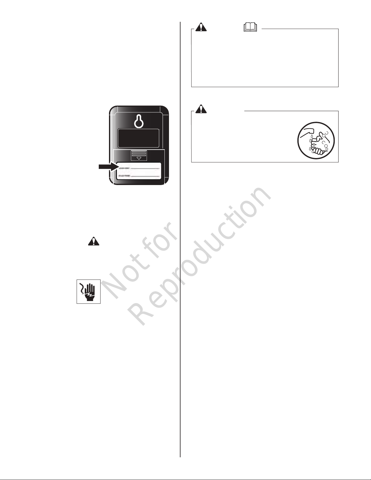
Safety
WARNING
Failure to read and follow the safety warnings and
instructions in this document and in the operator’s
manual could result in death, serious injury, and/or
property damage.
The warnings and instructions must be read,
understood, and followed when setting-up, operating,
servicing, transporting, or storing the unit.
WARNING
Certain components in this product
and related accessories contain
chemicals known to the State of
California to cause cancer, birth
defects, or other reproductive harm.
Wash hands after handling.
This device complies with part 15 of the FCC Rules.
Operation is subject to the following two conditions: (1)
This device may not cause harmful interference, and
(2) this device must accept any interference received,
including interference that may cause undesired
operation.
The safety alert symbol is used to identify
safety information about hazards that can result in
personal injury. A signal word (DANGER, WARNING, or
CAUTION) is used with the alert symbol to indicate the
likelihood and the potential severity of injury. In addition,
a hazard symbol
may be used to
represent the type
of hazard.
DANGER indicates a hazard which, if not avoided,
will result in death or serious injury.
WARNING
could result in death or serious injury.
indicates a hazard which, if not avoided,
CAUTION indicates a hazard which, if not avoided,
could result in minor or moderate injury.
NOTICE: indicates a situation that could result in
damage to the product.
Only current licensed electrical professionals should
attempt installation of this accessory. Installation must
strictly comply with all applicable codes, industry
standards and regulations.
2
Page 3
Not for
Reproduction
Preparation
Installation
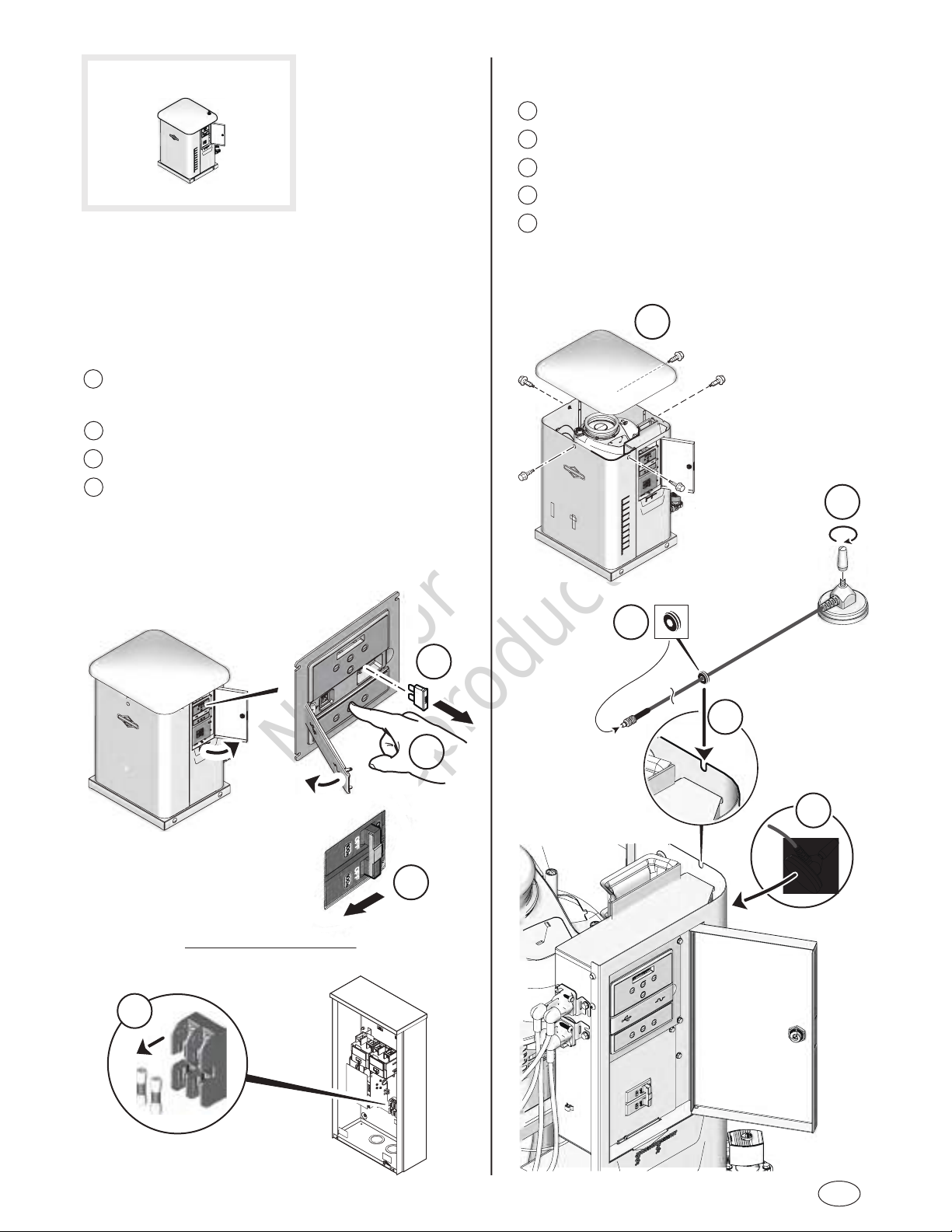
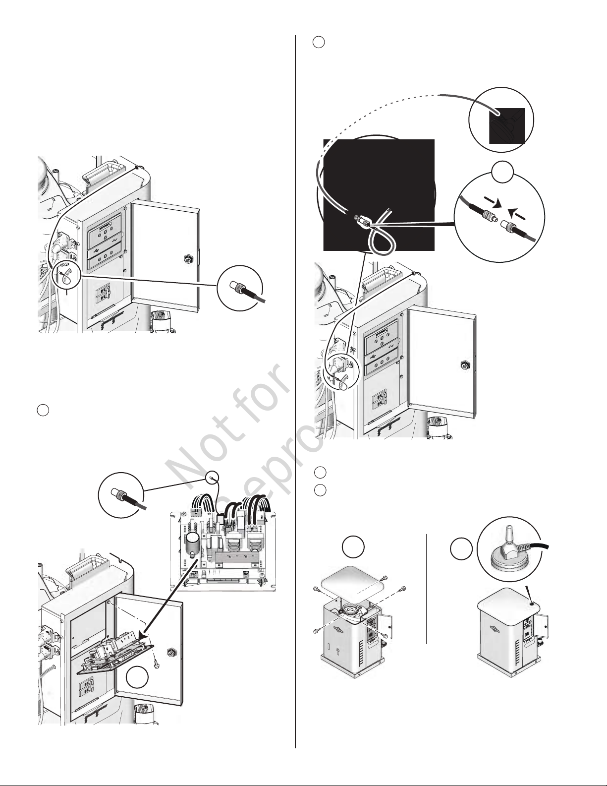
1 Remove the five screws and roof.
2 Assemble antenna piece to base.
3 Install grommet on antenna wire.
4 Insert grommet and wire into slot on rear panel.
5 Attach antenna (temporarily) onto the back panel.
Before performing any generator maintenance, always
perform the following steps:
1 Set the generator’s circuit breaker to its OFF
position.
2 Press and hold the control panel OFF button.
3 Remove 15 Amp fuse from control panel.
4 Utility voltage is present at generator control
panel. Disconnect power before servicing control
panel by removing the fuses from the transfer
switch.
3
2
1
2
3
4
4
1
5
en
3
Page 4
Not for
Reproduction
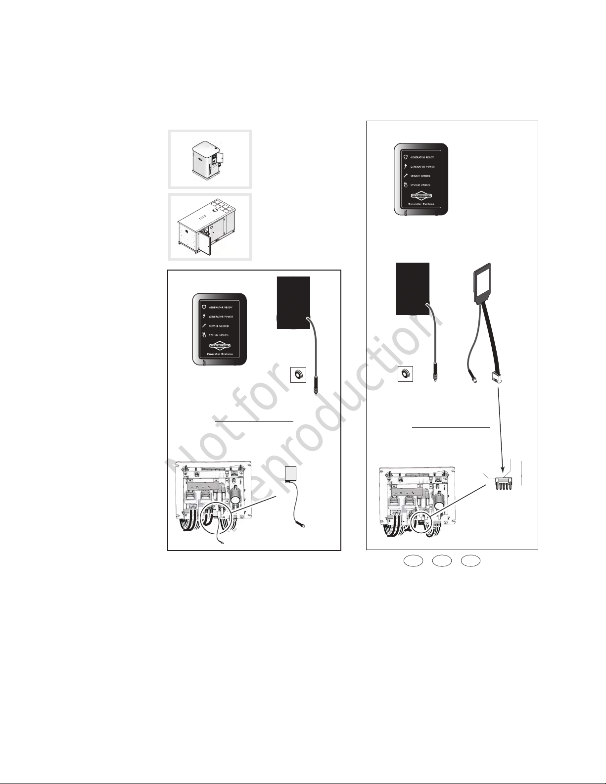
Option 1
Control Panel is equipped with an ON BOARD
RADIO.
A wire connection is available at the inside cabinet
electrical harness hole.
7 Insert the antenna wire to the ON BOARD RADIO
wire until it clicks. Route wire away from sharp
objects and secure with ties.
7
6 If the wire connection cannot be found, locate by
removing the four screws used to attach the control
panel.
6
8 Reinstall the roof.
9 Mount the antenna to the top of the roof.
8
9
4
After installation has been completed, replace fuses in
transfer switch, replace 15 Amp fuse in control panel,
and set generator circuit breaker to its ON position.
Go to: LINK MONITOR WITH GENERATOR.
Page 5

Not for
Reproduction
Option 2
OFF BOARD RADIO to be installed.
6 Remove screws on control panel and
tilt panel forward.
7 Prepare the OFF BOARD RADIO mounting surface
by cleaning with an alcohol wipe or other cleaning
solution. Make sure surface is dry before
proceeding to Step 8.
6
8
9
10
7
8 Remove RED plastic from adhesive on OFF
BOARD RADIO. Attach radio to inside wall under
control panel. Press down firmly.
9 Plug connector into control panel as shown.
10 Insert wire for antenna through side panel harness
hole.
11 Reinstall control panel and tighten screws securely.
12 Insert antenna wire to the OFF BOARD RADIO wire
until it clicks. Route wire away from sharp objects
and wire tie
13 Reinstall the roof.
14 Mount the antenna to the top of the roof.
11
12
14
13
After installation has been completed, replace fuses in
transfer switch, replace 15 Amp fuse in control panel,
and set generator circuit breaker to its ON position.
Go to: LINK MONITOR WITH GENERATOR.
en
5
Page 6

Not for
Reproduction
Notes
6
Page 7

Not for
Reproduction
Preparation
Before performing any generator maintenance, always
perform the following steps:
1 Set the generator’s circuit breaker to its OFF
position.
2 Press and hold the control panel OFF button.
3 Remove 15 Amp fuse from control panel.
4 Utility voltage is present at generator control
panel. Disconnect power before servicing control
panel by removing the fuses from the transfer
switch.
Installation
Option 1
Control Panel is equipped with an ON BOARD
RADIO
Kit parts required:
GENERATOR READY
GENERATOR POWER
SERVICE NEEDED
SYSTEM UPDATE
Generator Systems
1 Remove the four screws attaching the control panel.
2 Locate the ON BOARD RADIO wire connection.
4
1
3
1
2
2
en
7
Page 8

Not for
Reproduction
3 Insert the antenna wire through inside cabinet hole
and around the backside as shown.
4 Fasten the four screws attaching the control panel
5 Assemble antenna piece to base.
6 Loosen inside roof bolt in corner.
7 Mount the antenna to the top of the roof. While
lifting roof in corner, lay antenna wire in space
between rubber gaskets.
After installation has been completed, replace fuses in
transfer switch, replace 15 Amp fuse in control panel,
and set generator circuit breaker to its ON position.
Go to: LINK MONITOR WITH GENERATOR.
8 Insert antenna wire to the ON BOARD RADIO wire
until it clicks. Route wire away from sharp objects
and wire tie.
9 Tighten roof bolt (6) securely.
3
4
Option 2
OFF BOARD RADIO to be installed.
Kit parts required:
GENERATOR READY
GENERATOR POWER
SERVICE NEEDED
SYSTEM UPDATE
1
Remove the four screws attaching the control panel.
2 Prepare the mounting surface by cleaning with an
alcohol wipe or other cleaning solution. Make sure
surface is dry before proceeding to Step 3.
5
8
8
7
1
6
7/16
2
Page 9

Not for
Reproduction
3 Remove RED plastic from adhesive on OFF
BOARD RADIO. Attach radio to inside wall under
control panel. Press down firmly.
4 Insert the antenna wire through inside cabinet hole
and around the backside as shown.
5 Plug connector into control panel as shown.
6 Fasten the four screws attaching the control panel.
3
4
5
7 Assemble antenna piece to base.
8 Loosen inside roof bolt in corner.
9 Mount the antenna to the top of the roof. While
lifting roof in corner, lay antenna wire in space
between rubber gaskets.
10 Insert antenna wire to the OFF BOARD RADIO wire
until it clicks. Route wire away from sharp objects
and wire tie.
11 Tighten roof bolt (8) securely.
7
8
6
7/16
10
After installation has been completed, replace fuses in
transfer switch, replace 15 Amp fuse in control panel,
and set generator circuit breaker to its ON position.
Go to: LINK MONITOR WITH GENERATOR.
9
en
9
Page 10

Not for
Reproduction
Link Monitor with Generator
The REMOTE WIRELESS MONITOR
• Is for indoor use ONLY.
1 Press AUTO mode.
AUTO
auto
OROR
• Communicates with the generator
control panel.
• Has a range of up to 200 feet line
of sight.
COLOR / ICON
green GENERATOR READY
green GENERATOR POWER
red SERVICE NEEDED
BUTTON SYSTEM UPDATE
GENERATOR CONTROL PANEL
Three different styles, same button function.
MENU
OK
ESC
X
AUTO OFFMANUAL
2 Install batteries correctly.
GENERATOR READY will light for 5
seconds while the monitor starts up.
3 Press and hold together for about 5 seconds the
MENU and ESCAPE buttons.
• “LINKING MODE” will scroll across the digital
readout display.
MENU
OK
ESC
menu
ok
esc
OROR
X
auto off manual
10
menu
ok
esc
4 Press and hold for 10 seconds the
system update BUTTON on the monitor.
• All three icons should turn ON
solid after 10 seconds.
• Once link has been made - all
icons turn OFF.
• If link has been unsuccessful
the wrench icon - flashes
4 seconds ON, 4 seconds OFF.
Repeat Steps 3 and 4.
5 Important: Once the link has been made
(all icons turn OFF), press the OK button.
MENU
OK
NOTE: It may take up to 1 minute for the monitor to
begin displaying the generator status correctly.
menu
ok
OROR
Page 11

Not for
Reproduction
Monitor/Generator
Status Codes
COLOR / ICON
• Wireless Communication Lost - the wrench icon
will flash 20 fast pulses, then pause for 5 seconds,
and repeat the sequence until communication has
been restored. Communication lost issues can
typically be resolved by moving the wireless monitor
closer, within the home, to the standby generator.
See Optional Router Accessory Kit
• Linking Error or Not Linked - the wrench icon will
light red for 4 seconds, pause for 4 seconds, and
repeat the sequence until a successful link is
completed.
green GENERATOR READY
green GENERATOR POWER
red SERVICE NEEDED
BUTTON SYSTEM UPDATE
Generator Status
The wireless monitor receives data from the generator
every 10 minutes and displays the generator status
through 3 status icons
Pressing the SYSTEM UPDATE button will provide
current Generator Status by flashing the status icons.
When pressed, all 3 icons will flash until the generator
status is received.
GENERATOR READY - When active, the shield
icon will flash green once every 7 seconds. The
green shield icon indicates that the generator is
in AUTO mode and that it is ready to run in the
event of a loss of utility power.
GENERATOR POWER - When active, the power
icon will flash green every 7 seconds. The green
power icon indicates that the generator is
supplying power.
SERVICE NEEDED - When the wrench icon
flashes red, refer to the service codes on the
back of the monitor or to the troubleshooting
guide in the generator manual. Call the nearest
authorized service dealer if problem cannot be
fixed.
Icon Lighting Codes
• During the weekly exercise cycle, the generator
will run for 20 minutes, but it will not supply power to
the home. During the exercise cycle, the monitor will
continue blinking the green shield icon.
Service Code Descriptions - name and number of
flashes are listed on the back side of the wireless
monitor.
None of the service needed codes are cleared at the
wireless monitor. All alerts must be cleared at the
generator control panel.
Optional Router Accessory Kit
The monitor has a line of sight range of up to 200 feet,
but this distance will decrease if the signal has to pass
through walls or other objects.
If upon installation and setup of the wireless monitor
system communication is not reliable, Optional Router
Accessory Kit may be needed. See Authorized Dealer
for more information.
• No status icons illuminated - Generator in OFF
mode or check and replace batteries.
• Batteries Inserted - the shield icon will light for 5
seconds.
The router is a small extender that can be used to
expand the range of a generator wireless network so
that network devices can seamlessly communicate
with one another.
The router can be plugged into any standard 110VAC
outlet within the home.
en
11
Page 12

Not for
Reproduction
BRIGGS & STRATTON PRODUCTS WARRANTY POLICY January 2014
LIMITED WARRANTY
Briggs & Stratton warrants that, during the warranty period specied below, it will repair or replace, free of charge, any part that is defective in
material or workmanship or both. Transportation charges on product submitted for repair or replacement under this warranty must be borne by
purchaser. This warranty is eective for and is subject to the time periods and conditions stated below. For warranty service, nd the nearest
Authorized Service Dealer in our dealer locator map at www.briggsandstratton.com. The purchaser must contact the Authorized Service
Dealer, and then make the product available to the Authorized Service Dealer for inspection and testing.
There is no other express warranty. Implied warranties, including those of merchantability and tness for a particular purpose, are
limited to the warranty period listed below, or to the extent permitted by law. Liability for incidental or consequential damages are
excluded to the extent exclusion is permitted by law. Some states or countries do not allow limitations on how long an implied warranty
lasts, and some states or countries do not allow the exclusion or limitation of incidental or consequential damages, so the above limitation and
exclusion may not apply to you. This warranty gives you specic legal rights and you may also have other rights which vary from state to state
or country to country.**
WARRANTY PERIOD
Item Consumer Use Commercial Use
Accessory/Attachment/Equipment 12 months None
** In Australia - Our goods come with guarantees that cannot be excluded under the Australian Consumer Law. You are entitled to a replacement
or refund for a major failure and for compensation for any other reasonably foreseeable loss or damage. You are also entitled to have the goods
repaired or replaced if the goods fail to be of acceptable quality and the failure does not amount to a major failure. For warranty service, nd the
nearest Authorized Service Dealer in our dealer locator map at BRIGGSandSTRATTON.COM, or by calling 1300 274 447, or by emailing or
writing to salesenquires@briggsandstratton.com.au, Briggs & Stratton Australia Pty Ltd, 1 Moorebank Avenue, NSW, Australia, 2170.
The warranty period begins on the date of purchase by the rst retail or commercial consumer. “Consumer use” means personal residential
household use by a retail consumer. “Commercial use” means all other uses, including use for commercial, income producing or rental purposes.
Once a product has experienced commercial use, it shall thereafter be considered as a commercial use product for purposes of this warranty.
To ensure prompt and complete warranty coverage, register your product at the website shown above or at www.onlineproductregistration.com, or
mail the completed registration card (if provided), or call 1-800-743-4115 (in USA).
Save your proof of purchase receipt. If you do not provide proof of the initial purchase date at the time warranty service is requested, the
manufacturing date of the product will be used to determine the warranty period. Product registration is not required to obtain warranty service on
Briggs & Stratton products.
ABOUT YOUR WARRANTY
This warranty covers only defects in materials or workmanship. It does not cover damage caused by improper use or abuse, improper
maintenance or repair, or normal wear and tear.
Improper Use and Abuse - The proper, intended use of this product is described in the Operator’s Manual. Using the product in a way not
described in the Operator’s Manual or using the product after it has been damaged will not be covered under this warranty. Warranty coverage
will also not be provided if the serial number on the product has been removed or the product has been altered or modied in any way, or if the
product has evidence of abuse such as impact damage or water/chemical corrosion damage.
Improper Maintenance or Repair - This product must be maintained according to the procedures and schedules provided in the Operator’s
Manual, and serviced or repaired using genuine Briggs & Stratton parts or equivalent. Damage caused by lack of maintenance or use of nonoriginal parts is not covered by warranty.
Normal Wear and Tear - Like most mechanical devices, your unit is subject to wear even when properly maintained. This warranty does not
cover repairs when normal use has exhausted the life of a part or the equipment. Maintenance and wear items such as lters, belts, cutting blades,
and brake pads (except engine brake pads) are not covered by warranty due to wear characteristics alone, unless the cause is due to defects in
material or workmanship.
Other Exclusions - This warranty excludes damage due to accident, abuse, modications, alterations, improper servicing, freezing or chemical
deterioration. Attachments or accessories that were not originally packaged with the product are also excluded. This warranty does not include
used, reconditioned, second-hand, or demonstration equipment or engines. This warranty also excludes failures due to acts of God and other
force majeure events beyond the manufacturer’s control.
12
 Loading...