

Page 1
Manual No. 203903GS Revision - (06/04/2007)
BRIGGS & STRATTON POWER PRODUCTS GROUP, LLC
JEFFERSON, WISCONSIN, U.S.A.
Water Transfer Pump
Operator’s Manual
Page 2

2 BRIGGSandSTRATTON.COM
Briggs & Stratton Power Products Group, LLC
900 North Parkway
Jefferson, WI 53549
Copyright © 2007 Briggs & Stratton Power Products Group,
LLC. All rights reserved. No part of this material may be
reproduced or transmitted in any form by any means without
the express written permission of Briggs & Stratton Power
Products Group, LLC.
Thank you for purchasing this quality-built Briggs & Stratton water transfer pump. We are pleased that you’ve placed your
confidence in the Briggs & Stratton brand. When operated and maintained according to the instructions in this manual, your
Briggs & Stratton water transfer pump will provide many years of dependable service.
This manual contains safety information to make you aware of the hazards and risks associated with water transfer pumps
and how to avoid them. This water transfer pump is designed and intended only for pumping water that is not for human
consumption and is not intended for any other purpose. It is important that you read and understand these instructions
thoroughly before attempting to start or operate this equipment. Save these instructions for future reference.
This water transfer pump requires final assembly before use. Refer to the Assembly section of this manual for instructions
on final assembly procedures. Follow the instructions completely.
Where to Find Us
You never have to look far to find Briggs & Stratton support and service for your water transfer pump. Consult your Yellow
Pages. There are over 30,000 Briggs & Stratton authorized service dealers worldwide who provide quality service. You can
also contact Briggs & Stratton Customer Service by phone at (800) 743-4115, or on the Internet at
BRIGGSandSTRATTON.COM.
Water Transfer Pump
Model Number
Revision
Serial Number
Engine
Model Number
Type Number
Code Number
Date Purchased
Page 3
Table of Contents
Operator Safety . . . . . . . . . . . . . . . . . . . . . . . . . . . . . . . . . 4
Equipment Description. . . . . . . . . . . . . . . . . . . . . . . . . . . . . . . . . . . . . . . . . 4
Safety Rules. . . . . . . . . . . . . . . . . . . . . . . . . . . . . . . . . . . . . . . . . . . . . . . . . 4
Assembly . . . . . . . . . . . . . . . . . . . . . . . . . . . . . . . . . . . . . 7
Unpack Water Transfer Pump . . . . . . . . . . . . . . . . . . . . . . . . . . . . . . . . . . . 7
Attach Anti-Vibration Pads. . . . . . . . . . . . . . . . . . . . . . . . . . . . . . . . . . . . . . 7
Add Engine Oil . . . . . . . . . . . . . . . . . . . . . . . . . . . . . . . . . . . . . . . . . . . . . . . 7
Add Fuel. . . . . . . . . . . . . . . . . . . . . . . . . . . . . . . . . . . . . . . . . . . . . . . . . . . . 7
Attach Suction Hose . . . . . . . . . . . . . . . . . . . . . . . . . . . . . . . . . . . . . . . . . . 8
Connect Discharge Hose (Optional). . . . . . . . . . . . . . . . . . . . . . . . . . . . . . . 9
Features and Controls . . . . . . . . . . . . . . . . . . . . . . . . . . . . 10
Operation . . . . . . . . . . . . . . . . . . . . . . . . . . . . . . . . . . . . 11
Safe Operating Considerations. . . . . . . . . . . . . . . . . . . . . . . . . . . . . . . . . . 11
Move Water Pump to Safe Operating Location . . . . . . . . . . . . . . . . . . . . . 11
Prime the Water Pump . . . . . . . . . . . . . . . . . . . . . . . . . . . . . . . . . . . . . . . 12
Locate Strainer Basket Into Water Source . . . . . . . . . . . . . . . . . . . . . . . . . 12
Starting the Water Pump . . . . . . . . . . . . . . . . . . . . . . . . . . . . . . . . . . . . . . 13
Stopping the Water Pump . . . . . . . . . . . . . . . . . . . . . . . . . . . . . . . . . . . . . 14
Maintenance . . . . . . . . . . . . . . . . . . . . . . . . . . . . . . . . . . 15
Maintenance Schedule. . . . . . . . . . . . . . . . . . . . . . . . . . . . . . . . . . . . . . . . 15
Water Pump Maintenance . . . . . . . . . . . . . . . . . . . . . . . . . . . . . . . . . . . . . 15
Engine Maintenance. . . . . . . . . . . . . . . . . . . . . . . . . . . . . . . . . . . . . . . . . . 16
Storage . . . . . . . . . . . . . . . . . . . . . . . . . . . . . . . . . . . . . . . . . . . . . . . . . . . 19
Troubleshooting . . . . . . . . . . . . . . . . . . . . . . . . . . . . . . . . 20
Warranties. . . . . . . . . . . . . . . . . . . . . . . . . . . . . . . . . . . . 21
Emissions Control System Warranty . . . . . . . . . . . . . . . . . . . . . . . . . . . . . 21
Water Transfer Pump Owner Warranty . . . . . . . . . . . . . . . . . . . . . . . . . . . 23
Specifications . . . . . . . . . . . . . . . . . . . . . . . . . . . . . . . . . 24
Product Specifications. . . . . . . . . . . . . . . . . . . . . . . . . . . . . . . . . . . . . . . . 24
Common Service Parts . . . . . . . . . . . . . . . . . . . . . . . . . . . . . . . . . . . . . . . 24
3
FrançaisEspañol
Page 4
Operator Safety
Equipment Description
Read this manual carefully and become familiar
with your water pump. Know its applications, its
limitations and any hazards involved.
This water pump can be used to transfer water from a
flooded or unwanted location such as a basement. It can
also be used for draining swimming pools or for irrigation.
Every effort has been made to ensure that information in this
manual is accurate and current. However, we reserve the
right to change, alter or otherwise improve the product and
this document at any time without prior notice.
The Emissions Control System for this water pump is
warranted for standards set by the Environmental Protection
Agency and the California Air Resources Board.
Safety Rules
This is the safety alert symbol. It is used to alert
you to potential personal injury hazards. Obey all
safety messages that follow this symbol to avoid
possible injury or death.
The safety alert symbol ( ) is used with a signal word
(DANGER, CAUTION, WARNING), a pictorial and/or a safety
message to alert you to hazards. DANGER indicates a hazard
which, if not avoided, will result in death or serious injury.
WARNING indicates a hazard which, if not avoided, could
result in death or serious injury. CAUTION indicates a hazard
which, if not avoided, might result in minor or moderate
injury. NOTICE, indicates a situation that could result in
equipment damage. Follow safety messages to avoid or
reduce the risk of injury or death.
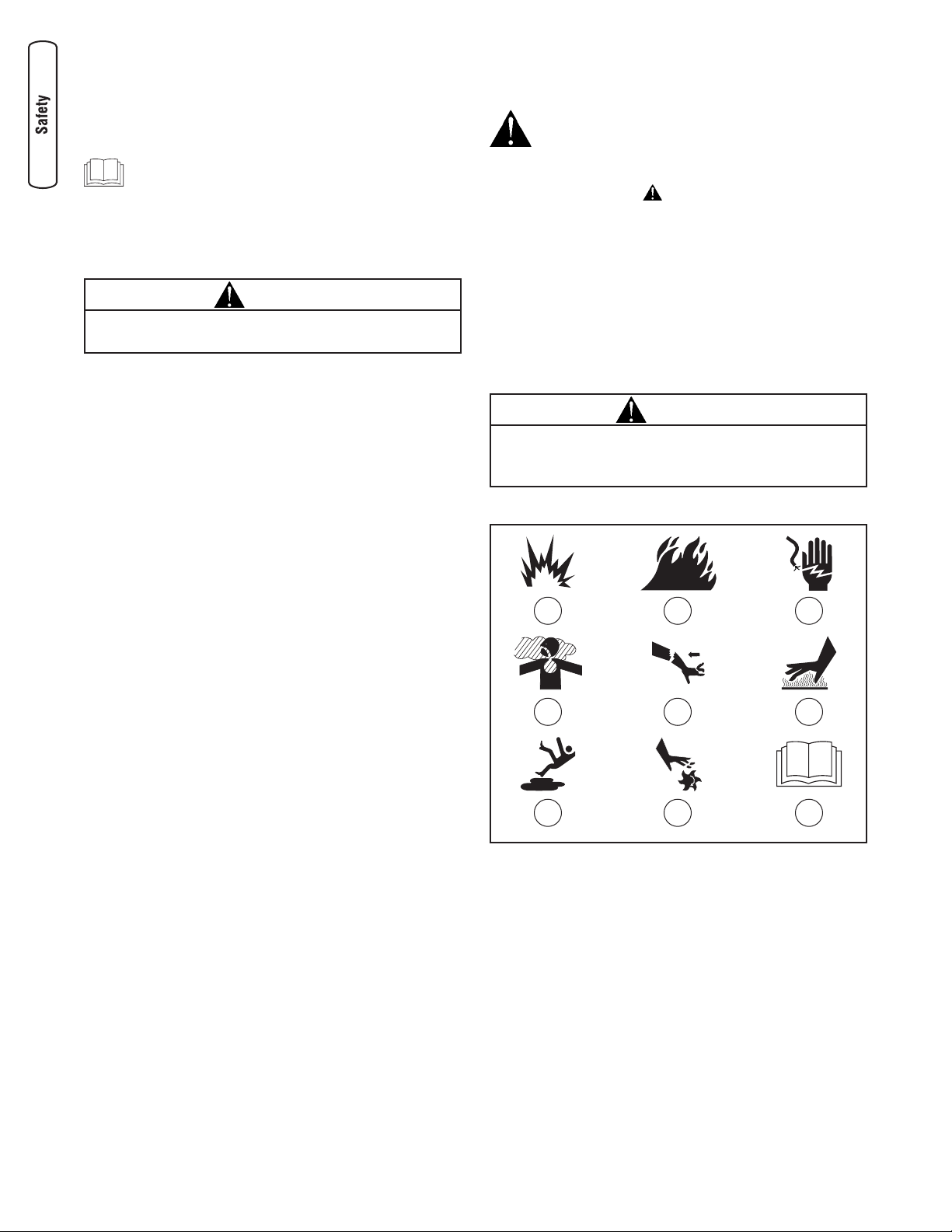
Hazard Symbols and Meanings
A - Explosion F - Hot Surface
B - Fire G - Slippery Surface
C - Electric Shock H - Moving Parts
D - Toxic Fumes J - Read Manual
E - Kickback
4 BRIGGSandSTRATTON.COM
WARNING
The engine exhaust from this product contains chemicals
known to the State of California to cause cancer, birth
defects, or other reproductive harm.
A B C
D E
G H
F
J
CAUTION
These water pumps are manufactured to pump ONLY clear
water that is not intended for human consumption.
Page 5
5
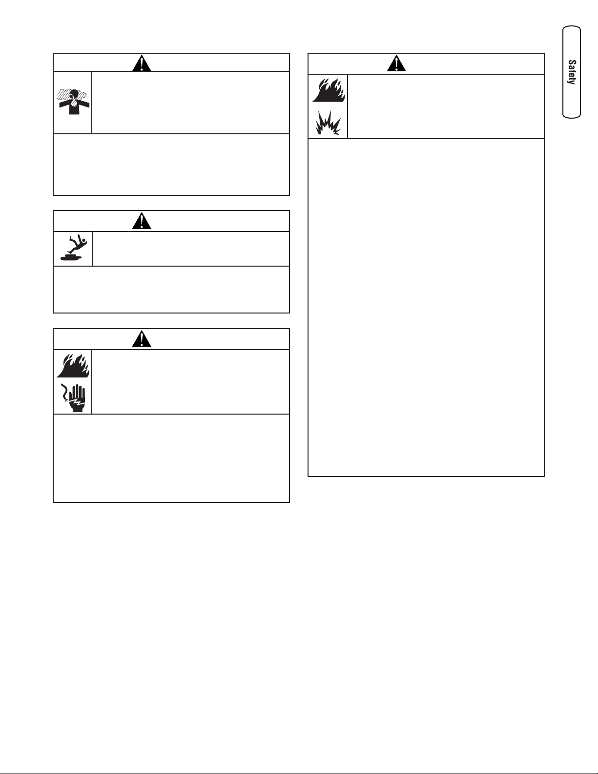
WARNING
Use of water transfer pump can create puddles
and slippery surfaces.
• Operate water transfer pump from a stable surface.
• The area should have adequate slopes and drainage to reduce
the possibility of a fall due to slippery surfaces.
WARNING
Fuel and its vapors are extremely flammable and
explosive.
Fire or explosion can cause severe burns or
death.
WHEN ADDING OR DRAINING FUEL
• Turn water transfer pump OFF and let it cool at least 2 minutes
before removing fuel cap. Loosen cap slowly to relieve pressure
in tank.
• Fill or drain fuel tank outdoors.
• DO NOT overfill tank. Allow space for fuel expansion.
• If fuel spills, wait until it evaporates before starting engine.
• Keep fuel away from sparks, open flames, pilot lights, heat, and
other ignition sources.
• DO NOT light a cigarette or smoke.
WHEN STARTING EQUIPMENT
• Ensure spark plug, muffler, fuel cap, and air cleaner are in place.
• DO NOT crank engine with spark plug removed.
WHEN OPERATING EQUIPMENT
• DO NOT pump flammable liquids, such as fuel or fuel oils.
• This water pump is not for use in mobile equipment or marine
applications.
• DO NOT tip engine or equipment at angle which causes fuel
to spill.
• Secure water pump. Loads from hoses may cause tipover.
WHEN TRANSPORTING OR REPAIRING EQUIPMENT
• Transport/repair with fuel tank EMPTY or with fuel shutoff
valve OFF.
• Disconnect spark plug wire.
WHEN STORING FUEL OR EQUIPMENT WITH FUEL IN TANK
• Store away from furnaces, stoves, water heaters, clothes dryers,
or other appliances that have pilot light or other ignition source
because they can ignite fuel vapors.
WARNING
Running engine gives off carbon monoxide, an
odorless, colorless, poison gas.
Breathing carbon monoxide can cause headache,
fatigue, dizziness, vomiting, confusion, seizures,
nausea, fainting or death.
• Operate water transfer pump ONLY outdoors.
• Keep exhaust gas from entering a confined area through
windows, doors, ventilation intakes, or other openings.
• DO NOT start or run engine indoors or in an enclosed area, even
if windows and doors are open.
WARNING
Unintentional sparking can result in fire or
electric shock.
WHEN ADJUSTING OR MAKING REPAIRS TO YOUR WATER
TRANSFER PUMP
• Disconnect the spark plug wire from the spark plug and place
the wire where it cannot contact spark plug.
WHEN TESTING FOR ENGINE SPARK
• Use approved spark plug tester.
• DO NOT check for spark with spark plug removed.
Page 6
6 BRIGGSandSTRATTON.COM
WARNING
Contact with muffler area can result in serious
burns.
Exhaust heat/gases can ignite combustibles,
structures or damage fuel tank causing a fire.
• DO NOT touch hot parts and AVOID hot exhaust gases.
• Allow equipment to cool before touching.
• Keep at least 5 feet (1.5 m) of clearance on all sides of water
transfer pump including overhead.
• Code of Federal Regulation (CFR) Title 36 Parks, Forests, and
Public Property require equipment powered by an internal
combustion engine to have a spark arrester, maintained in
effective working order, complying to USDA Forest service
standard 5100-1C or later revision. In the State of California a
spark arrester is required under section 4442 of the California
Public resources code. Other states may have similar laws.
WARNING
Starter and other rotating parts can entangle
hands, hair, clothing, or accessories.
• NEVER place hands or body parts inside of running pump or
hoses.
• NEVER operate water transfer pump without protective housing
or covers.
• DO NOT wear loose clothing, jewelry or anything that may be
caught in the starter or other rotating parts.
• Tie up long hair and remove jewelry.
NOTICE
Improper treatment of water transfer pump can damage it
and shorten its life.
• If you have questions about intended use, ask dealer or contact
qualified service center.
• Be sure pump chamber is filled with water before starting the
engine. Never run pump without priming.
• Use a non-collapsible hose on the suction side of pump.
• Use water pump only for intended uses.
• Pumping sea water, beverages, acids, chemical solutions, or any
other liquid that promotes corrosion can damage the pump.
• Ensure all connections are air tight.
• DO NOT obstruct the suction or discharge hose in any way.
• NEVER operate pump without strainer basket connected to end
of suction hose.
• DO NOT exceed suction head maximum of 8m (25 ft.) and total
head of 32m (106 ft.). Use shortest suction head possible (see
page 10).
• NEVER allow vehicles to drive over hoses. If a hose must be
positioned across a roadway, use planking on each side of hose
to allow vehicles to pass over without obstructing or collapsing
hose.
• Anchor pump to avoid “walking” or equipment movement,
especially if located near a ditch or edge of open ravine. The
equipment could fall in.
• Keep equipment away from edge of river or lake where it could
cause the bank to collapse.
• DO NOT insert any objects through cooling slots.
• NEVER operate units with broken or missing parts, or without
protective housing or covers.
• DO NOT by-pass any safety device on this machine.
• NEVER move machine by pulling on hoses. Use frame on unit.
• Check fuel system for leaks or signs of deterioration, such as
chafed or spongy hose, loose or missing clamps, or damaged
tank or cap. Correct all defects before operating water transfer
pump.
• This equipment is designed to be used with Briggs & Stratton
Power Products authorized parts ONLY. If equipment is used
with parts that DO NOT comply with minimum specifications,
user assumes all risks and liabilities.
CAUTION
Excessively high operating speeds increase risk of injury
and damage to water pump.
Excessively low speeds impose a heavy load.
• DO NOT tamper with governed speed.
• DO NOT modify water pump in any way.
• DO NOT allow unqualified persons or children to operate or
service water pump.
WARNING
Starter cord kickback (rapid retraction) can result
in bodily injury. Kickback will pull hand and arm
toward engine faster than you can let go.
Broken bones, fractures, bruises, or sprains
could result.
Keep hands and body clear from discharge of
pump.
• When starting engine, pull cord slowly until resistance is felt and
then pull rapidly to avoid kickback.
• Secure discharge hose to avoid whipping.
Page 7
7
Assembly
Read entire operator’s manual before you attempt
to assemble or operate your new water transfer
pump.
Your water transfer pump requires some assembly and is
ready for use after it has been properly serviced with the
recommended oil and fuel.
If you have any problems with the assembly of your water
transfer pump, please call the water transfer pump helpline
at (800) 743-4115. If calling for assistance, please have the
model, revision, and serial number from the data tag
available. See Controls section for data tag location.
Unpack Water Transfer Pump
1. Remove the parts bag, accessories, and inserts
included with water transfer pump.
2. Open carton completely by cutting each corner from
top to bottom.
3. Ensure you have all included items prior to assembly.
Items in the carton include:
• Water pump
• Oil bottle
• Parts bag (which includes the following):
• This operator’s manual
• Owner’s registration card
• Strainer basket and barb
• Hose barb (2)
• Barb cuff (2)
• Rubber seal (2)
• Hose clamp (3)
• Anti-vibration kit
• Anti-vibration pad (4)
• Bolt (4)
• Washer (4)
• Lock nut (4)
• Instruction sheet
To prepare your water transfer pump for operation, you
will need to perform these tasks:
1. Fill out and send in registration card.
2. Attach anti-vibration pads.
3. Add oil to engine crankcase.
4. Add fuel to fuel tank.
5. Attach suction hose.
6. Connect discharge hose (optional).
7. Move water pump to safe operating location.
8. Prime the water pump.
9. Locate strainer basket into water source.
Attach Anti-Vibration Pads
You will need the following tools to install the anti-vibration
pads:
• 10mm wrench
• Socket wrench with a 10mm socket
Attach anti-vibration pads to water pump as shown on
instruction sheet included with anti-vibration kit.
IMPORTANT: You must attach anti-vibration pads prior to
adding engine oil and fuel.
Add Engine Oil
1. Place water transfer pump on a flat, level surface.
2. Clean area around oil fill and remove yellow oil fill cap.
NOTE: See Oil Recommendations in Maintenance section.
Verify provided oil bottle is the correct viscosity for current
ambient temperature.
3. Using oil funnel (optional), slowly pour contents of
provided oil bottle into oil fill opening.
4. Replace oil fill cap and fully tighten.
Add Fuel
Fuel must meet these requirements:
• Clean, fresh, unleaded gasoline.
• A minimum of 87 octane/87 AKI (91 RON). High
altitude use, see High Altitude.
• Gasoline with up to 10% ethanol (gasohol) or up to
15% MTBE (methyl tertiary butyl ether) is acceptable.
To protect the fuel system from gum formation, mix in a fuel
stabilizer when adding fuel. See Storage. All fuel is not the
same. If you experience starting or performance problems
after using fuel, switch to a different fuel provider or change
brands. This engine is certified to operate on gasoline. The
emission control system for this engine is EM (Engine
Modifications).
NOTICE
Improper treatment of water transfer pump can damage it
and shorten its life.
• DO NOT attempt to crank or start the engine before it has been
properly serviced with the recommended oil. This may result in
an engine failure.
NOTICE
Avoid water transfer pump damage.
Failure to follow Operator’s Manual for fuel
recommendations voids warranty.
• DO NOT use unapproved gasoline such as E85.
• DO NOT mix oil in gasoline.
• DO NOT modify engine to run on alternate fuels.
Page 8
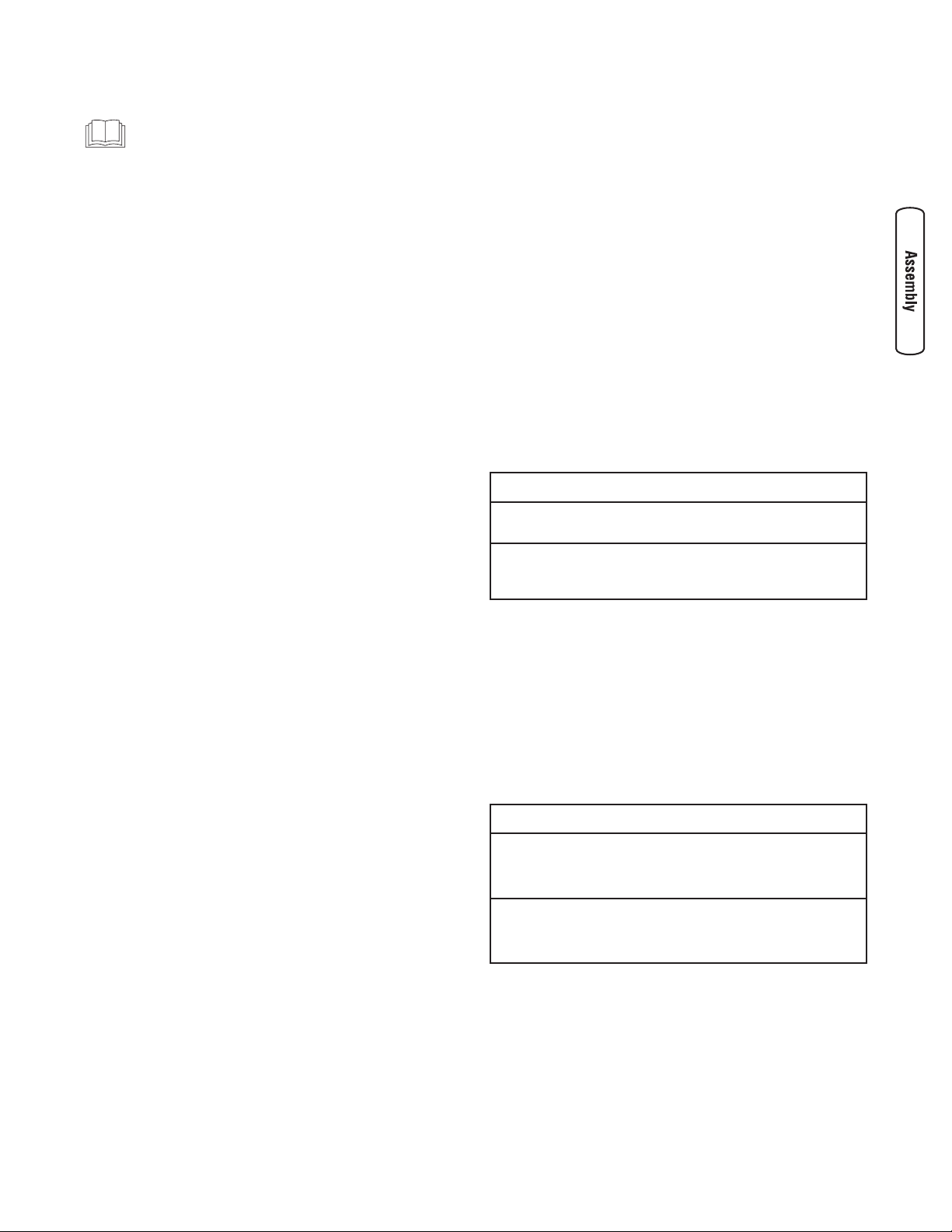
1. Clean area around fuel fill cap, remove cap.
2. Slowly add regular unleaded fuel to fuel tank. Fill to red
level indicator (A). Be careful not to overfill.
3. Install fuel cap and let any spilled fuel evaporate before
starting engine.
High Altitude
At altitudes over 5,000 feet (1524 meters), a minimum
85 octane / 85 AKI (89 RON) gasoline is acceptable. To
remain emissions compliant, high altitude adjustment is
required. Operation without this adjustment will cause
decreased performance, increased fuel consumption, and
increased emissions. See an Authorized Briggs & Stratton
dealer for high altitude adjustment information. Operation of
the engine at altitudes below 2,500 feet (762 meters) with
the high altitude kit is not recommended.
Attach Suction Hose
You will need the following tool to install the hoses to the
water pump:
• 1/4" or 6mm standard screwdriver
Connect Suction Hose to Pump
Use a commercially available hose. The suction hose must
be reinforced with a non-collapsible wall or braided material.
DO NOT use a hose with an inside diameter smaller than the
pumps suction port size.
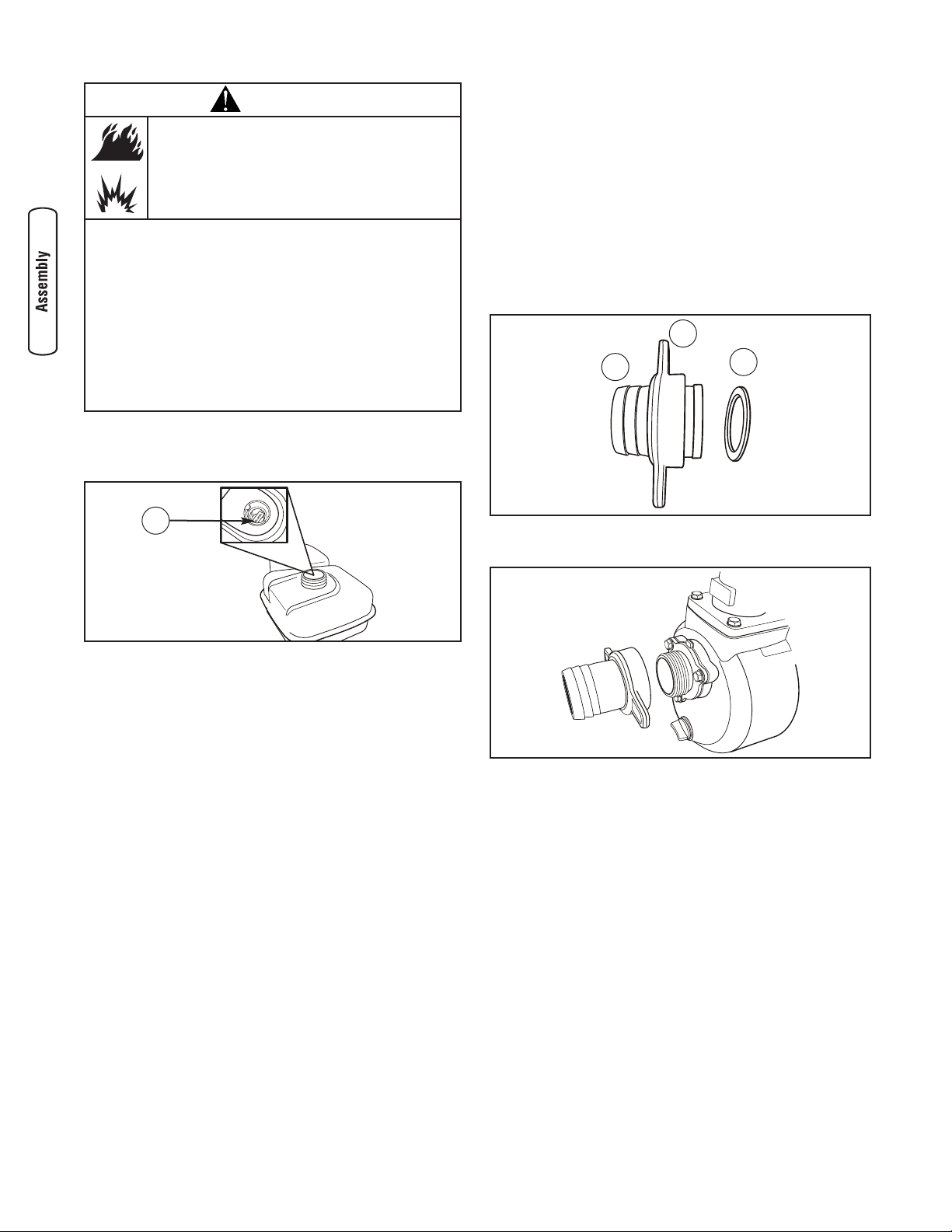
1. Slide barb cuff (B) over hose barb (C). Insert rubber
seal (D) into end of barb cuff.
2. Screw hose barb assembly onto pump in clockwise
rotation until hose barb assembly is tightened securely.
8 BRIGGSandSTRATTON.COM
WARNING
Fuel and its vapors are extremely flammable and
explosive.
Fire or explosion can cause severe burns or
death.
WHEN ADDING FUEL
• Turn water transfer pump OFF and let it cool at least 2 minutes
before removing fuel cap. Loosen cap slowly to relieve pressure
in tank.
• Fill fuel tank outdoors.
• DO NOT overfill tank. Allow space for fuel expansion.
• If fuel spills, wait until it evaporates before starting engine.
• Keep fuel away from sparks, open flames, pilot lights, heat, and
other ignition sources.
• DO NOT light a cigarette or smoke.
A
D
B
C
Page 9
9
3. Slide hose clamp (A) over end of hose (B). Slide
suction hose onto hose barb (C). Tighten hose clamp
securely using a standard 1/4” (6mm) screwdriver.
Attach Suction Hose to Strainer Basket
Slide hose clamp over hose. Attach open end of suction hose
to strainer hose barb. Tighten hose clamp securely using a
standard 1/4” (6mm) screwdriver.
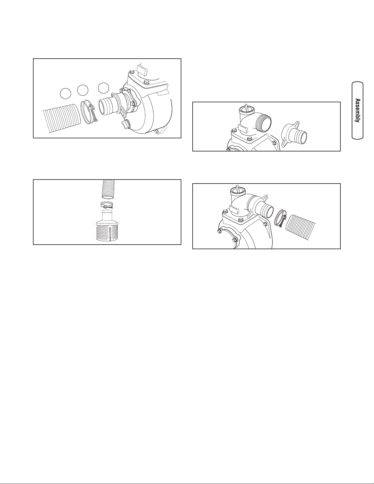
Connect Discharge Hose (Optional)
If desired, use a commercially available hose. DO NOT use a
hose with an inside diameter smaller than the pump’s
discharge port size.
1. Slide barb cuff over hose barb. Insert rubber seal into
end of barb cuff as shown earler.
2. Screw hose barb assembly onto pump in clockwise
rotation until hose barb assembly is tightened securely.
3. Slide hose clamp over end of discharge hose. Slide
discharge hose onto hose barb. Tighten hose clamp
securely using a standard 1/4” (6mm) screwdriver.
C
A
B
Page 10

10 BRIGGSandSTRATTON.COM
A - Fuel Tank — Fill tank with regular unleaded fuel. Always
leave room for fuel expansion.
B - Priming Plug — Fill pump with water here to prime
pump before starting.
C - Discharge Outlet — Connect discharge hose here.
D - Choke Lever — Prepares a cold engine for starting.
E - Air Cleaner — Protects engine by filtering dust and
debris out of intake air.
F - Recoil Starter — Used for starting the engine manually.
G - Engine Speed Lever — Used to adjust engine speed to
control pump output.
H - On/Off Switch — Set this switch to “On” before using
recoil starter. Set switch to “Off” to stop a running
engine.
J - Oil Drain — Drain engine oil here.
K - Oil Fill — Check and add engine oil here.
L - Data Tag — Provides model and serial number of water
transfer pump. Please have these readily available if
calling for assistance.
M - Suction Inlet — Connect reinforced suction hose here.
N - Water Drain Plug — Remove to drain water from pump
and flush internal components with clean water.
P - Pump Chamber — Be sure to fill with water before
starting.
R - Engine Information — Stamped on valve cover. Provides
model, type and code number of engine. Please have
these readily available when calling for assistance.
S - Fuel Shutoff Valve — Used to turn fuel supply on and
off to engine.
Item Not Shown:
Strainer Basket — Used to limit passage of abrasive
materials into the pump.
10 BRIGGSandSTRATTON.COM
G
E
J
F
K
D
Unit may vary slightly from that shown
Features and Controls
Read this Operator’s Manual and safety rules before operating your water transfer pump.
Compare the illustrations with your water transfer pump, to familiarize yourself with the locations of various controls
and adjustments. Save this manual for future reference.
H L M N P S
CBA
R
Page 11
11
Operation
If you have any problems operating your water transfer
pump, please call the water transfer pump helpline at
(800) 743-4115.
Safe Operating Considerations
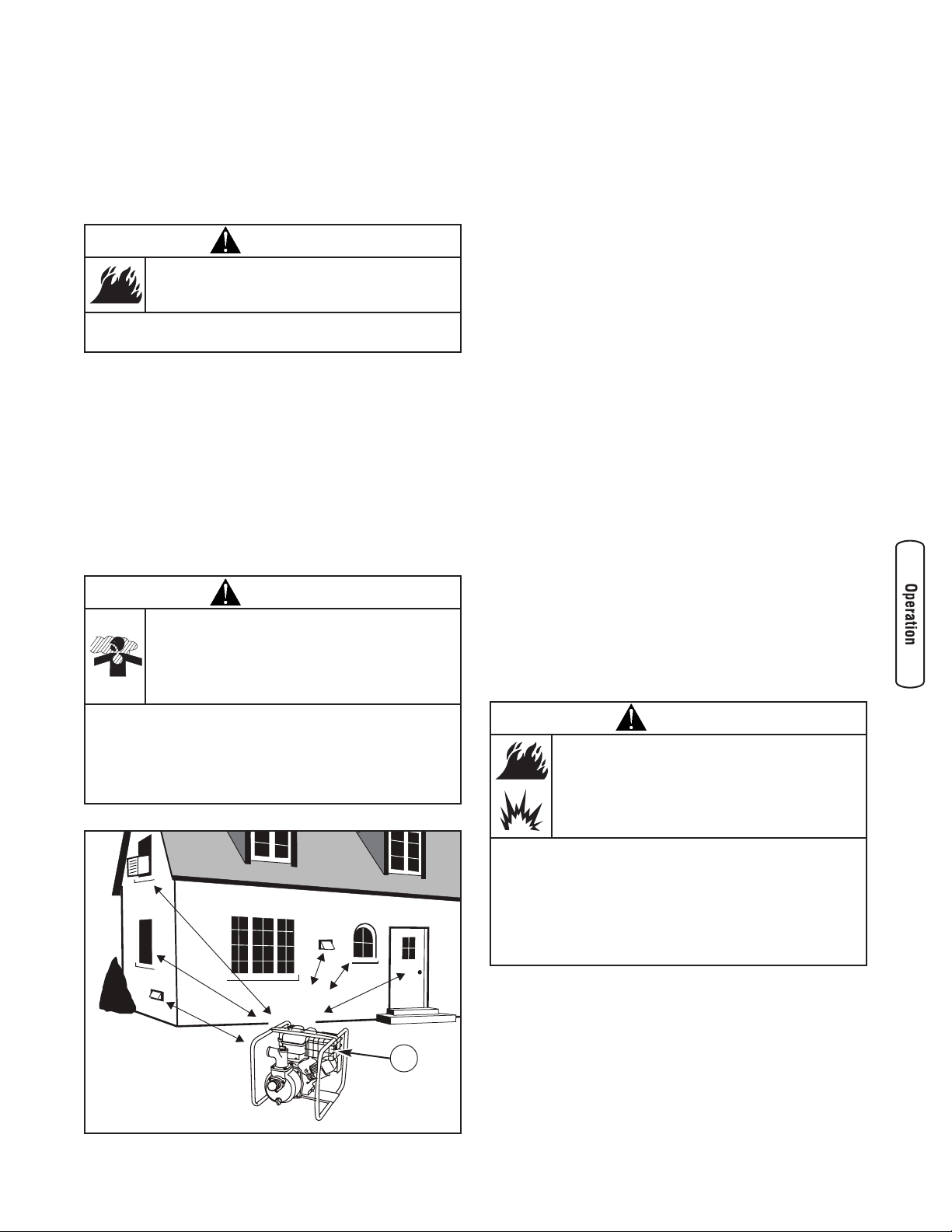
Clearances and Air Movement
Place water transfer pump outdoors in an area that will not
accumulate deadly exhaust gas. DO NOT place water transfer
pump where exhaust gas (A) could accumulate and enter
inside or be drawn into a potentially occupied building.
Ensure exhaust gas is kept away from any windows, doors,
ventilation intakes, or other openings that can allow exhaust
gas to collect in a confined area. Prevailing winds and air
currents should be taken into consideration when positioning
water transfer pump.
What is “Head”?
Head refers to the height of a column of water that can be
delivered by the discharge of the pump.
Suction Head is the vertical distance between the center of
the pump and the surface of the liquid on the suction side of
the pump. May also be referred to as “suction lift”. The
atmospheric pressure of 14.7 psi at sea level limits suction
head lift to less than approximately 26 feet for any pump.
Discharge Head is the vertical distance between the pump’s
discharge port and the point of discharge, which is the liquid
surface if the hose is submerged or pumping into the bottom
of a tank.
Total Head is the sum of the suction head value plus the
discharge head value.
As water pumping height increases, pump output decreases.
The length, type, and size of the suction and discharge hoses
can also significantly affect pump output.
It is important for the suction operation to be the shorter
part of the total pumping action. This will decrease the
priming time and improve pump performance by increasing
the discharge head.
Suction head is a maximum of 25 feet and discharge head
should be a maximum of 81 feet. Total head can not be more
than 106 feet as shown on next page.
Move Water Pump to Safe Operating Location
For best pump performance, locate the pump on a flat, level
surface as close as possible to the water to be pumped.
Secure water pump to avoid tipover. Use hoses that are no
longer than necessary.
IMPORTANT: Direct open end of discharge hose away from
home, electrical devices or anything not desired to get wet.
WARNING
Exhaust heat/gases can ignite combustibles,
structures or damage fuel tank causing a fire.
• Keep at least 5 ft. (1.5 m) clearance on all sides of water
transfer pump including overhead.
WARNING
Running engine gives off carbon monoxide, an
odorless, colorless, poison gas.
Breathing carbon monoxide can cause headache,
fatigue, dizziness, vomiting, confusion, seizures,
nausea, fainting or death.
• Operate water transfer pump ONLY outdoors.
• Keep exhaust gas from entering a confined area through
windows, doors, ventilation intakes, or other openings.
• DO NOT start or run engine indoors or in an enclosed area, even
if windows and doors are open.
A
WARNING
Fuel and its vapors are extremely flammable and
explosive.
Fire or explosion can cause severe burns or
death.
WHEN OPERATING EQUIPMENT
• This water pump is not for use in mobile equipment or marine
applications.
• DO NOT tip engine or equipment at angle which causes fuel to
spill.
• Secure water pump. Loads from hoses may cause tip over.
Page 12
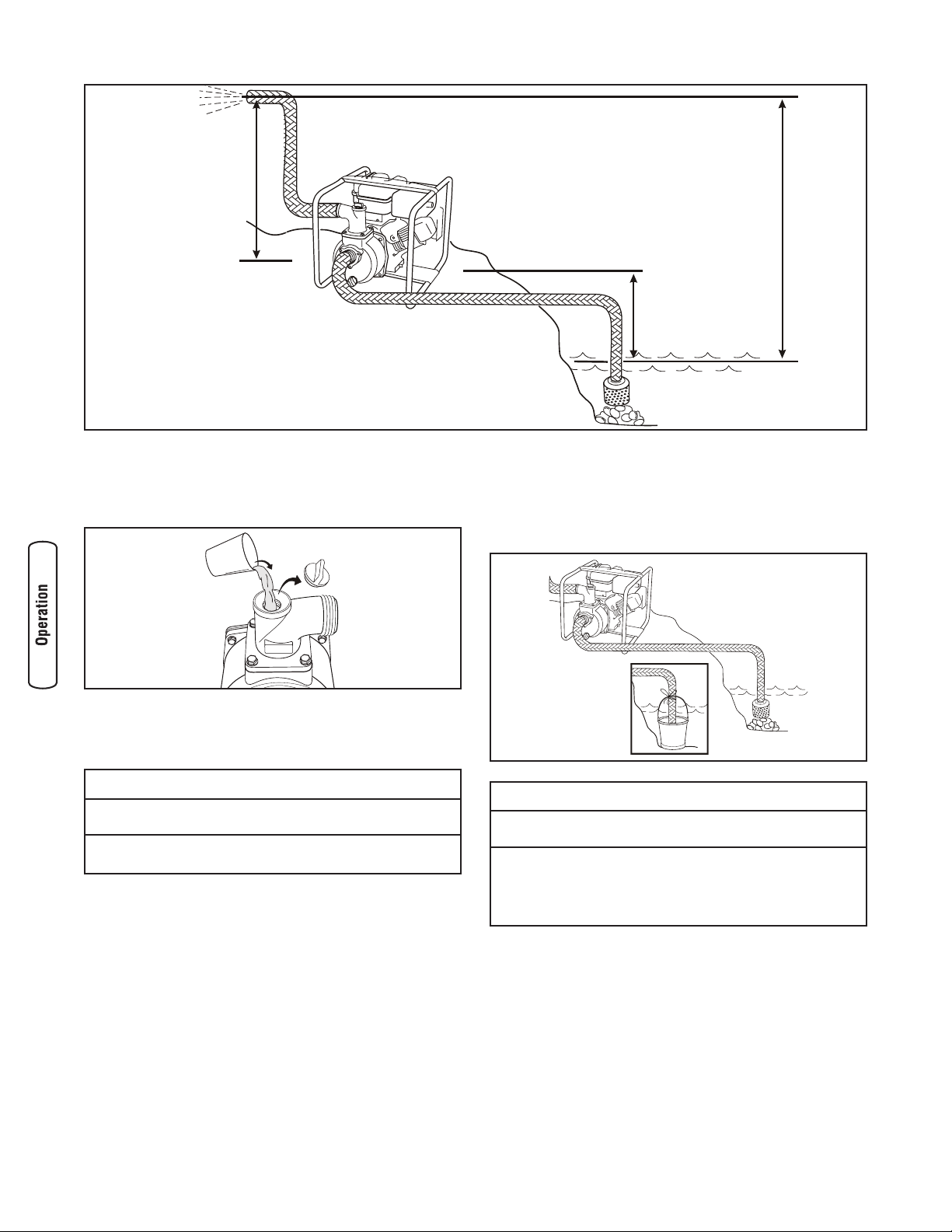
Prime the Water Pump
1. Remove priming plug from top of pump.
2. Fill pump with clean, clear water up to top of discharge
outlet.
3. Replace priming plug.
Locate Strainer Basket Into Water Source
Place strainer basket into water to be pumped. Basket must
be fully immersed in water.
12 BRIGGSandSTRATTON.COM
Discharge Head
- 81 feet (25m)
Maximum
Suction Head
- 25 feet (8m)
Maximum
Total Head
- 106 feet (32m)
Maximum
NOTICE
Improper treatment of water pump can damage it and
shorten its life.
• Be sure pump chamber is filled with water before starting the
engine. NEVER run pump without priming.
NOTICE
Improper treatment of water pump can damage it and
shorten its life.
• NEVER operate pump without strainer connected to end of
suction hose.
• Keep strainer out of sand or silt, place in bucket or on stones.
• DO NOT let pump run dry or damage to seals may result.
Page 13
13
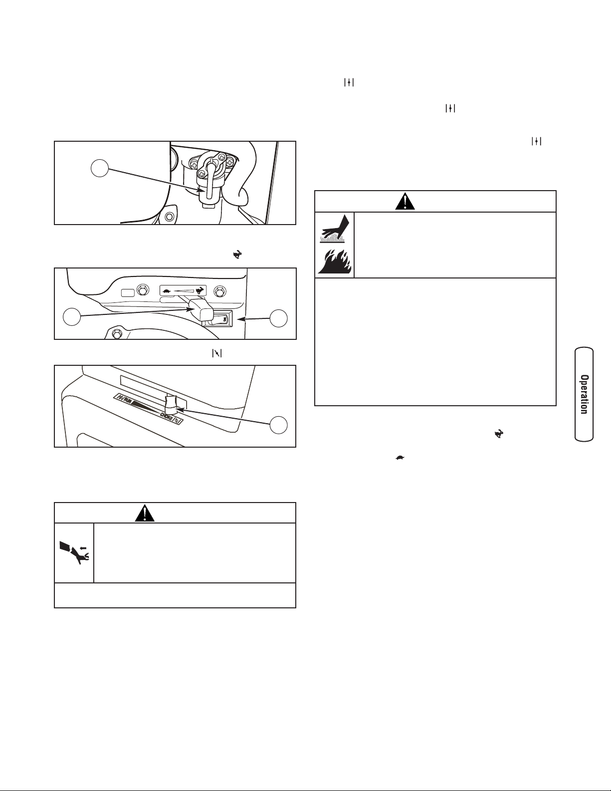
Starting the Water Pump
Use the following start instructions:
1. Make sure unit is on a flat, level surface and pump
chamber is primed.
2. Turn fuel valve (A) to “On” position. The fuel valve
handle will be vertical (pointing toward the ground).
3. Push on/off switch (B) to “On” position.
4. Move engine speed lever (C) to “Fast” ( ) position.
5. Move choke lever (D) to “Choke” ( ) position.
6. Grasp recoil handle and pull slowly until slight
resistance is felt. Then pull handle rapidly to overcome
compression, prevent kickback and start engine.
IMPORTANT: If excessive fuel is present in the air/fuel
mixture causing a “flooded” condition, move choke lever to
“Run” ( ) position and pull handle repeatedly until engine
starts.
7. Move choke lever to “Run” ( ) position a short
distance at a time over several seconds in warm weather
or minutes in cold weather. Let engine run smoothly
before each change. Operate with choke in “Run” ( )
position.
IMPORTANT: It may take a few minutes for water pump to
begin pumping water.
Pump output is controlled by adjusting engine speed.
Moving the engine speed lever in the “Fast” ( ) direction
will increase pump output, and moving the engine speed
lever in the “Slow” ( ) direction will decrease pump output.
WARNING
Contact with muffler area can result in serious
burns.
Exhaust heat/gases can ignite combustibles,
structures or damage fuel tank causing a fire.
• DO NOT touch hot parts and AVOID hot exhaust gases.
• Allow equipment to cool before touching.
• Keep at least 5 feet (1.5 m) of clearance on all sides of water
transfer pump including overhead.
• Code of Federal Regulation (CFR) Title 36 Parks, Forests, and
Public Property require equipment powered by an internal
combustion engine to have a spark arrester, maintained in
effective working order, complying to USDA Forest service
standard 5100-1C or later revision. In the State of California a
spark arrester is required under section 4442 of the California
Public resources code. Other states may have similar laws.
WARNING
Starter cord kickback (rapid retraction) can result
in bodily injury. Kickback will pull hand and arm
toward engine faster than you can let go.
Broken bones, fractures, bruises, or sprains
could result.
• When starting engine, pull cord slowly until resistance is felt and
then pull rapidly to avoid kickback.
A
B
C
D
Page 14
Stopping the Water Pump
1. Move engine speed lever to “Slow” ( ) position.
2. Push on/off switch to “Off” position.
3. Turn fuel valve to “Off” position.
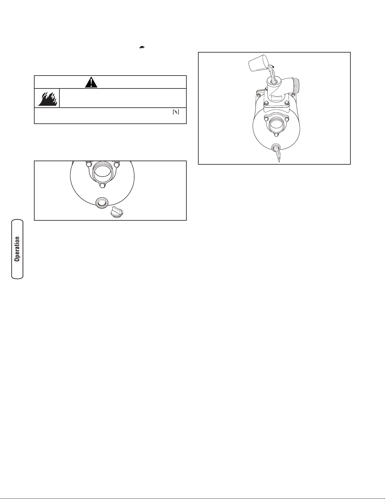
Drain and Flush Water Pump
1. Disconnect and drain suction and discharge hoses.
2. Remove drain plug at bottom of pump.
3. Remove primer plug from top of pump and flush
internal components of pump with clean water.
4. Replace both plugs and finger tighten.
14 BRIGGSandSTRATTON.COM
WARNING
Backfire, fire or engine damage could occur.
• DO NOT stop engine by moving choke control to “Choke” ()
position.
Page 15
15
Maintenance
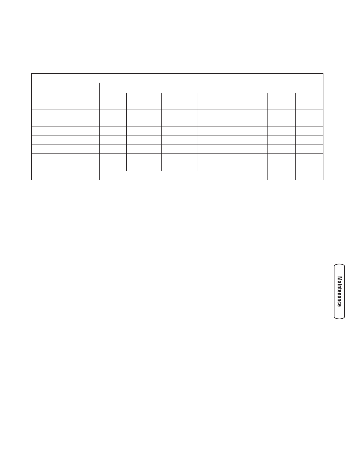
Maintenance Schedule
Follow the hourly or calendar intervals, whichever occurs first. More frequent service is required when operating in adverse
conditions noted below.
1
Change oil after the first (5) operating hours and every 50 hours or every year, whichever occurs first, thereafter. Change oil sooner when operating under dirty or dusty conditions.
2
Replace more often under dirty or dusty conditions.
General Recommendations
Regular maintenance will improve the performance and
extend the life of the water pump. See any authorized Briggs
& Stratton dealer for service.
The water pump’s warranty does not cover items that have
been subjected to operator abuse or negligence. To receive
full value from the warranty, the operator must maintain
water pump as instructed in this manual.
Some adjustments will need to be made periodically to
properly maintain your water pump.
All service and adjustments should be made at least once
each season. Follow the requirements in the Maintenance
Schedule chart above.
NOTE: Once a year you should clean or replace the spark
plug and replace the air filter. A new spark plug and clean air
filter assure proper fuel-air mixture and help your engine run
better and last longer.
Emissions Control
Maintenance, replacement, or repair of the emissions
control devices and systems may be performed by any
non-road engine repair establishment or individual.
However, to obtain ”no charge” emissions control service,
the work must be performed by a factory authorized dealer.
See the Emissions Warranty.
Water Pump Maintenance
Maintenance consists of keeping the water pump clean.
Store the unit in a clean dry environment where it will not be
exposed to excessive dust, dirt, moisture or any corrosive
vapors. Cooling air slots in the water pumps engine must not
become clogged with dirt, leaves or any other foreign
material.
NOTE: DO NOT use a garden hose to clean water pumps
engine. Water can enter engine fuel system and cause
problems.
Maintenance Schedule - Fill in Dates as You Complete Regular Service
Maintenance Task
Service Intervals
Service Dates
Before
Each Use
Every 25 Hours
or Yearly
Every 50 Hours
or Yearly
Every 100 Hours
or Yearly
Clean debris
X
Check oil level
X
Change engine oil
X
1
Service air cleaner
X
2
Service spark plug
X
Service spark arrester
X
Clean cooling system
X
2
Prepare for storage
If unit is to remain idle for longer than 30 days.
Page 16
16 BRIGGSandSTRATTON.COM
Cleaning
Daily or before use, look around and underneath water pump
for signs of oil or fuel leaks. Clean accumulated debris from
inside and outside water pump. Keep linkage, spring and
other engine controls clean. Keep area around and behind
muffler free from any combustible debris. Use low pressure
air (not to exceed 25 psi) to blow away dirt. Inspect cooling air
slots and opening on water pump. These openings must be
kept clean and unobstructed.
Engine parts should be kept clean to reduce the risk of
overheating and ignition of accumulated debris.
• Use a damp cloth to wipe exterior surfaces clean.
• Use a soft bristle brush to loosen caked on dirt or oil.
• Use a vacuum cleaner to pick up loose dirt and debris.
Remove silt and sludge buildup in pump body:
• Open priming plug and remove drain plug.
• Flush internal components of pump with clean water.
Engine Maintenance
Oil
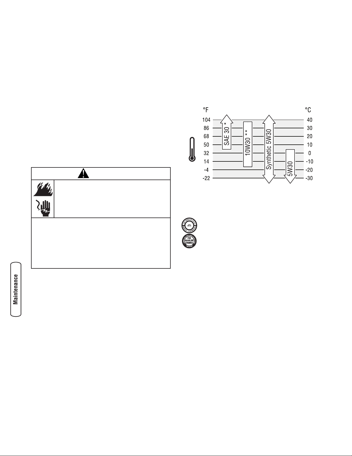
Oil Recommendations
We recommend the use of Briggs & Stratton Warranty
Certified oils for best performance. Other high-quality
detergent oils are acceptable if classified for service SF, SG,
SH, SJ or higher. DO NOT use special additives.
Outdoor temperatures determine the proper oil viscosity for
the engine. Use the chart to select the best viscosity for the
outdoor temperature range expected.
* Below 40°F (4°C) the use of SAE 30 will result in hard starting.
** Above 80°F (27°C) the use of 10W30 may cause increased oil
consumption. Check oil level more frequently.
NOTE: Synthetic oil meeting ILSAC GF-2, API
certification mark and API service symbol with
“SJ/CF ENERGY CONSERVING” or higher, is an
acceptable oil at all temperatures. Use of synthetic
oil does not alter required oil change intervals.
Checking Oil Level
Oil level should be checked prior to each use or at least
every 5 hours of operation. Keep oil level maintained.
1. Make sure water pump is on a level surface.
2. Clean area around oil fill and remove oil fill cap.
3. Verify oil is at the point of overflowing at oil fill opening.
4. Replace and tighten oil fill cap.
Adding Engine Oil
1. Make sure water pump is on a level surface.
2. Check oil level as described in Checking Oil Level.
3. If needed, slowly pour oil into oil fill opening to the
point of overflowing at oil fill.
4. Replace and tighten oil fill cap.
WARNING
Unintentional sparking can result in fire or
electric shock.
WHEN ADJUSTING OR MAKING REPAIRS TO YOUR WATER
PUMP
• Disconnect the spark plug wire from the spark plug and place
the wire where it cannot contact spark plug.
WHEN TESTING FOR ENGINE SPARK
• Use approved spark plug tester.
• DO NOT check for spark with spark plug removed.
Page 17
17
Changing Engine Oil
Change the oil after the first 5 hours of operation. Change oil
every 50 hours thereafter. If you are using your water pump
under extremely dirty or dusty conditions, or in extremely
hot weather, change the oil more often.
KEEP OUT OF REACH OF CHILDREN. DON’T
POLLUTE. CONSERVE RESOURCES. RETURN
USED OIL TO COLLECTION CENTERS.
Change the oil while the engine is still warm from running,
as follows:
1. Make sure water pump is on a level surface.
2. Disconnect the spark plug wire from the spark plug and
place the wire where it cannot contact spark plug.
3. Clean area around oil drain plug (A). The oil drain plug is
located at base of engine, opposite carburetor.
4. Remove oil drain plug and drain oil completely into a
suitable container.
5. Reinstall oil drain plug and tighten securely. Remove oil
fill cap.
6. Slowly pour oil (about 20 oz.) into oil fill opening (B)
to the point of overflowing (C) at oil fill cap. DO NOT
overfill.
7. Reinstall oil fill cap. Finger tighten cap securely.
8. Wipe up any spilled oil.
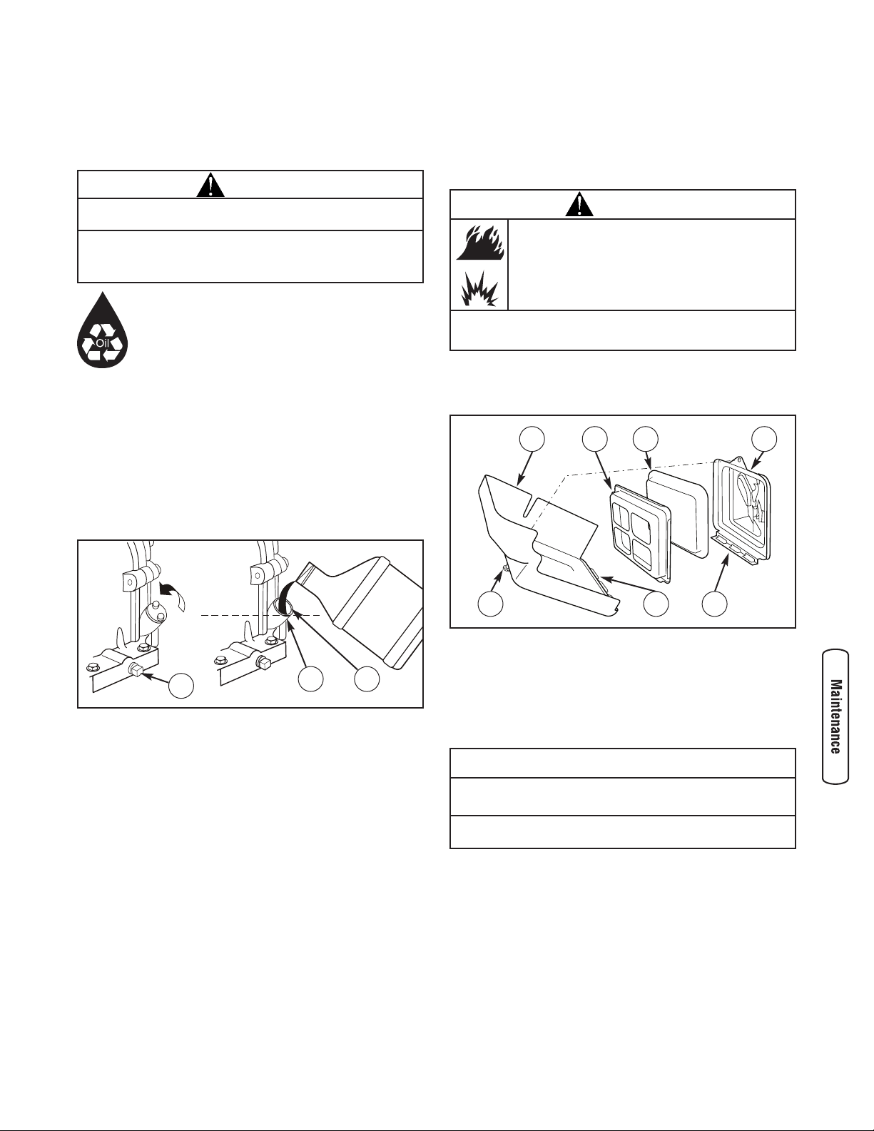
Service Air Cleaner
Your engine will not run properly and may be damaged if
you run it with a dirty air cleaner.
Clean or replace the air cleaner every 25 hours of operation
or once each year, whichever comes first. Clean or replace
more often if operating under dirty or dusty conditions.
To service the air cleaner, follow these steps:
1. Loosen screw (D) and tilt cover (E) down.
2. Remove air cleaner assembly from cover.
3. Carefully separate foam air cleaner (F) from air cleaner
plate (G).
4. Wash foam air cleaner in liquid detergent and water.
To dry, squeeze foam air cleaner in a clean cloth.
5. Saturate foam air cleaner with clean engine oil.
To remove excess oil, squeeze foam air cleaner in a
clean cloth.
6. Reinstall cleaned and oiled foam air cleaner in
air cleaner plate.
7. Firmly fit air cleaner assembly into cover.
8. Insert cover’s tabs (H) into slots (J) in bottom of base (K).
9. Tilt cover up and tighten screw securely to base.
NOTICE
DO NOT use pressurized air or solvents to clean the foam
air cleaner.
• Pressurized air can damage the foam air cleaner and solvents
will dissolve the foam air cleaner.
WARNING
Fuel and its vapors are extremely flammable and
explosive.
Fire or explosion can cause severe burns or
death.
• NEVER start or run the engine with the air cleaner assembly or
the foam air cleaner removed.
F
D
E
H
G K
J
CAUTION
Avoid prolonged or repeated skin contact with used motor
oil.
• Used motor oil has been shown to cause skin cancer in certain
laboratory animals.
• Thoroughly wash exposed areas with soap and water.
A
B
C
Page 18
18 BRIGGSandSTRATTON.COM
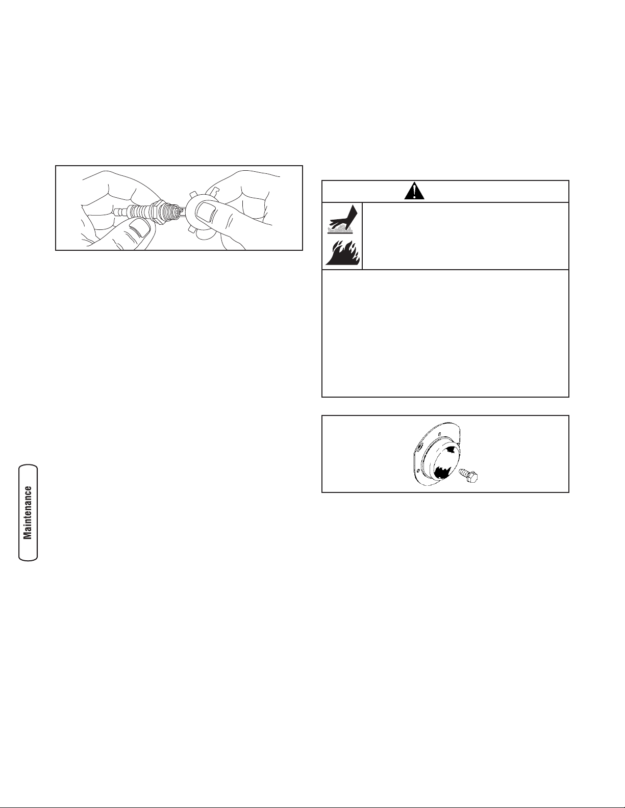
Service Spark Plug
Change the spark plug every 100 hours of operation or once
each year, whichever comes first. This will help your engine
to start easier and run better.
1. Clean area around spark plug.
2. Remove and inspect spark plug.
3. Check electrode gap with wire feeler gauge and set
spark plug gap to 0.030 inch (0.76mm) if necessary.
4. Replace spark plug if electrodes are pitted, burned or
porcelain is cracked. Use the recommended
replacement plug. See Specifications.
5. Install spark plug and tighten firmly.
Clean Spark Arrester Screen
The engine exhaust muffler may be equipped a spark arrester
screen. If equipped, inspect and clean the screen every
50 hours of operation or once each year, whichever comes first.
If you use your water pump on any forest-covered, brushcovered, or grass-covered unimproved land, it must have a
spark arrester. The spark arrester must be maintained in
good condition by the owner/operator.
If the engine has been running, the muffler will be very hot.
Allow the muffler to cool before servicing the spark arrester.
1. Remove spark arrester screen for cleaning and inspection.
2. Inspect screen and replace if torn, perforated or
otherwise damaged. DO NOT use a defective screen. If
screen is not damaged, clean it with commercial solvent.
3. Reattach spark arrester screen to muffler.
NOTE: You can purchase a new spark arrester screen by
contacting your local Briggs & Stratton service center.
Air Cooling System
Over time debris may accumulate in cylinder cooling fins and
cannot be removed without partial engine disassembly. For
this reason, we recommend you have an authorized Briggs &
Stratton service dealer clean the cooling system per
recommended intervals (see Maintenance Schedule in
beginning of Maintenance section). Equally important is to
keep top of engine free from debris. See Cleaning.
WARNING
Contact with muffler area can result in serious
burns.
Exhaust heat/gases can ignite combustibles,
structures or damage fuel tank causing a fire.
• DO NOT touch hot parts and AVOID hot exhaust gases.
• Allow equipment to cool before touching.
• Keep at least 5 feet (1.5 m) of clearance on all sides of water
pump including overhead.
• Code of Federal Regulation (CFR) Title 36 Parks, Forests, and
Public Property require equipment powered by an internal
combustion engine to have a spark arrester, maintained in
effective working order, complying to USDA Forest service
standard 5100-1C or later revision. In the State of California a
spark arrester is required under section 4442 of the California
Public resources code. Other states may have similar laws.
Page 19
19
Storage
The water pump should be started at least once every seven
days and allowed to run at least 30 minutes. If this cannot be
done and you must store the unit for more than 30 days, use
the following information as a guide to prepare it for storage.
Long Term Storage Instructions
It is important to prevent gum deposits from forming in
essential fuel system parts, such as the carburetor, fuel filter,
fuel hose or tank during storage. Also, experience indicates
that alcohol-blended fuels (called gasohol, ethanol or
methanol) can attract moisture, which leads to separation
and formation of acids during storage. Acidic fuel can
damage the fuel system of an engine while in storage.
Protect Fuel System
Fuel Additive:
Fuel can become stale when stored over 30 days. Stale fuel
causes acid and gum deposits to form in the fuel system or
on essential carburetor parts. To keep fuel fresh, use Briggs
& Stratton FRESH START™ fuel stabilizer, available as a
liquid additive or a drip concentrate cartridge.
There is no need to drain gasoline from the engine if a fuel
stabilizer is added according to instructions. Run the engine
for 2 minutes to circulate the stabilizer throughout the fuel
system. The engine and fuel can then be stored up to
24 months.
If gasoline in the engine has not been treated with a fuel
stabilizer, it must be drained into an approved container. Run
the engine until it stops from lack of fuel. The use of a fuel
stabilizer in the storage container is recommended to
maintain freshness.
Change Engine Oil
While engine is still warm, drain oil from crankcase. Refill
with recommended grade. See Changing Engine Oil in Engine
Maintenance.
Oil Cylinder Bore
• Remove spark plug and pour about 1/2 ounce (15 ml)
of clean engine oil into the cylinder.
• Install spark plug and pull starter handle slowly to
distribute oil.
Water Pump
1. Drain water pump as described in Drain and Flush
Water Pump.
2. Clean water pump as described in Cleaning.
3. Check that openings on water pump are open and
unobstructed.
Other Storage Tips
1. DO NOT store fuel from one season to another unless it
has been treated as described in Protect Fuel System.
2. Replace fuel can if it starts to rust. Contaminated fuel
will cause engine problems.
3. Cover unit with a suitable protective cover that does not
retain moisture.
4. Store water pump in clean, dry area.
WARNING
Fuel and its vapors are extremely flammable and
explosive.
Fire or explosion can cause severe burns or
death.
WHEN STORING FUEL OR EQUIPMENT WITH FUEL IN TANK
• Store away from furnaces, stoves, water heaters, clothes dryers,
or other appliances that have pilot light or other ignition source
because they can ignite fuel vapors.
WHEN DRAINING FUEL
• Turn water pump OFF and let it cool at least 2 minutes before
removing fuel cap. Loosen cap slowly to relieve pressure in
tank.
• Drain fuel tank outdoors.
• Keep fuel away from sparks, open flames, pilot lights, heat, and
other ignition sources.
• DO NOT light a cigarette or smoke.
WARNING
Unintentional sparking can result in fire or
electric shock.
• NEVER pull starter handle with spark plug removed.
WARNING
Storage covers can be flammable.
• DO NOT place a storage cover over a hot water pump.
• Let equipment cool for a sufficient time before placing the cover
on the equipment.
Page 20

20 BRIGGSandSTRATTON.COM
Troubleshooting
Problem Cause Correction
No pump output or low pump
output when water pump is
running.
1. Pump not primed.
2. Suction hose restricted, collapsed,
damaged, too long, or diameter too
small.
3. Strainer not completely under water.
4. Air leak at suction hose connector.
5. Strainer clogged.
6. Discharge hose restricted, damaged, too
long, or diameter too small.
7. Excessive or marginal head.
8. Engine speed lever is in “Slow” position.
1. Fill pump chamber with water and
prime pump.
2. Replace suction hose.
3. Sink the strainer and the end of
suction hose completely under water.
4. Replace sealing washer if missing or
damaged. Tighten hose connector
and clamp.
5. Clean debris from strainer.
6. Replace discharge hose.
7. Relocate pump and/or hoses to
reduce head.
8. Move engine speed lever to “Fast”
position.
Engine will not start; lacks
power; starts and runs rough;
or "hunts" or falters.
1. Rocker switch set to "Off".
2. Fuel valve is in "Off" position.
3. Dirty air cleaner.
4. Out of fuel.
5. Stale or contaminated fuel or water in
fuel.
6. Spark plug wire not connected to spark
plug.
7. Bad spark plug.
8. Excessive fuel is present in the air/fuel
mixture causing a “flooded” condition.
9. Carburetor is out of adjustment.
1. Set switch to "On".
2. Turn fuel valve to "On" position.
3. Clean or replace air cleaner.
4. Wait two minutes and fill fuel tank.
5. Drain fuel tank and carburetor; fill
with fresh fuel.
6. Connect wire to spark plug.
7. Replace spark plug.
8. Wait 5 minutes and re-crank engine.
9. Contact Authorized service facility.
Engine shuts down when
running.
Out of fuel. Wait two minutes and fill fuel tank.
Page 21

Warranties
Emissions Control System Warranty
Briggs & Stratton Corporation (B&S), the California Air
Resources Board (CARB) and the United States
Environmental Protection Agency (U.S. EPA)
Emissions Control System Warranty Statement (Owner’s
Defect Warranty Rights and Obligations)
California, United States and Canada Emissions Control
Defects Warranty Statement
The California Air Resources Board (CARB), U.S. EPA and
B&S are pleased to explain the Emissions Control System
Warranty on your small off-road engine (SORE). In
California, new small off-road engines model year 2006 and
later must be designed, built and equipped to meet the
State’s stringent anti-smog standards. Elsewhere in the
United States, new non-road, spark-ignition engines certified
for model year 1997 and later must meet similar standards
set forth by the U.S. EPA. B&S must warrant the emissions
control system on your engine for the periods of time listed
below, provided there has been no abuse, neglect or
improper maintenance of your small off-road engine.
Your emissions control system includes parts such as the
carburetor, air cleaner, ignition system, fuel line, muffler and
catalytic converter. Also included may be connectors and
other emissions related assemblies.
Where a warrantable condition exists, B&S will repair your
small off-road engine at no cost to you including diagnosis,
parts and labor.
Briggs & Stratton Emissions Control Defects Warranty
Coverage
Small off-road engines are warranted relative to emissions
control parts defects for a period of two years, subject to
provisions set forth below. If any covered part on your
engine is defective, the part will be repaired or replaced by
B&S.
Owner’s Warranty Responsibilities
As the small off-road engine owner, you are responsible for
the performance of the required maintenance listed in your
Operating and Maintenance Instructions. B&S recommends
that you retain all your receipts covering maintenance on
your small off-road engine, but B&S cannot deny warranty
solely for the lack of receipts or for your failure to ensure the
performance of all scheduled maintenance.
As the small off-road engine owner, you should however be
aware that B&S may deny you warranty coverage if your
small off-road engine or a part has failed due to abuse,
neglect, improper maintenance or unapproved modifications.
You are responsible for presenting your small off-road engine
to an Authorized B&S Service Dealer as soon as a problem
exists. The undisputed warranty repairs should be completed
in a reasonable amount of time, not to exceed 30 days.
If you have any questions regarding your warranty rights and
responsibilities, you should contact a B&S Service
Representative at (414) 259-5262.
The emissions warranty is a defects warranty. Defects are
judged on normal engine performance. The warranty is not
related to an in-use emissions test.
Briggs & Stratton Emissions Control Defects Warranty
Provisions
The following are specific provisions relative to your
Emissions Control Defects Warranty Coverage. It is in
addition to the B&S engine warranty for non-regulated
engines found in the Operator’s Manual.
1. Warranted Parts
Coverage under this warranty extends only to the parts
listed below (the emissions control systems parts) to
the extent these parts were present on the engine
purchased.
a. Fuel Metering System
• Cold start enrichment system (soft choke)
• Carburetor and internal parts
• Fuel Pump
• Fuel line, fuel line fittings, clamps
• Fuel tank, cap and tether
• Carbon canister
b. Air Induction System
• Air cleaner
• Intake manifold
• Purge and vent line
c. Ignition System
• Spark plug(s)
• Magneto ignition system
d. Catalyst System
• Catalytic converter
• Exhaust manifold
• Air injection system or pulse valve
e. Miscellaneous Items Used in Above Systems
• Vacuum, temperature, position, time sensitive
valves and switches
• Connectors and assemblies
21
Page 22

22 BRIGGSandSTRATTON.COM
2. Length of Coverage
B&S warrants to the initial owner and each subsequent
purchaser that the Warranted Parts shall be free from
defects in materials and workmanship which caused the
failure of the Warranted Parts for a period of two years
from the date the engine is delivered to a retail
purchaser.
3. No Charge
Repair or replacement of any Warranted Part will be
performed at no charge to the owner, including
diagnostic labor which leads to the determination that a
Warranted Part is defective, if the diagnostic work is
performed at an Authorized B&S Service Dealer. For
emissions warranty service contact your nearest
Authorized B&S Service Dealer as listed in the “Yellow
Pages” under “Engines, Gasoline,” “Gasoline Engines,”
“Lawn Mowers,” or similar category.
4. Claims and Coverage Exclusions
Warranty claims shall be filed in accordance with the
provisions of the B&S Engine Warranty Policy.
Warranty coverage shall be excluded for failures of
Warranted Parts which are not original B&S parts or
because of abuse, neglect or improper maintenance as
set forth in the B&S Engine Warranty Policy. B&S is not
liable to cover failures of Warranted Parts caused by
the use of add-on, non-original, or modified parts.
5. Maintenance
Any Warranted Part which is not scheduled for
replacement as required maintenance or which is
scheduled only for regular inspection to the effect of
“repair or replace as necessary” shall be warranted as
to defects for the warranty period. Any Warranted Part
which is scheduled for replacement as required
maintenance shall be warranted as to defects only for
the period of time up to the first scheduled replacement
for that part. Any replacement part that is equivalent in
performance and durability may be used in the
performance of any maintenance or repairs. The owner
is responsible for the performance of all required
maintenance, as defined in the B&S Operator’s Manual.
6. Consequential Coverage
Coverage hereunder shall extend to the failure of any
engine components caused by the failure of any
Warranted Part still under warranty.
Emission Information
Engines that are certified to meet the California Air
Resources Board (CARB) Tier 2 Emission Standards must
display information regarding the Emissions Durability
Period and Air Index. The engine manufacturer makes this
information available to the consumer on emission labels.
The engine emission label will indicate certification
information.
The Emissions Durability Period describes the number of
hours of actual running time for which the engine is certified
to be emissions compliant, assuming proper maintenance in
accordance with the Operating & Maintenance Instructions.
The following categories are used:
Moderate: Engine is certified to be emission compliant for
125 hours of actual engine running time.
Intermediate: Engine is certified to be emission compliant
for 250 hours of actual engine running time.
Extended: Engine is certified to be emission compliant for
500 hours of actual engine running time.
For example, a typical walk-behind lawn mower is used 20 to
25 hours per year. Therefore, the Emissions Durability
Period of an engine with an intermediate rating would
equate to 10 to 12 years.
Certain engines will be certified to meet the United States
Environmental Protection Agency (USEPA) Phase 2 emission
standards. For phase 2 certified engines, the Emissions
Compliance Period referred to on the Emissions Compliance
label indicates the number of operating hours for which the
engine has been shown to meet Federal emission
requirements.
For engines less than 225 cc displacement:
Category C = 125 hours
Category B = 250 hours
Category A = 500 hours.
For engines of 225 cc or more displacement:
Category C = 250 hours
Category B = 500 hours
Category A = 1000 hours.
Page 23

23
BRIGGS & STRATTON POWER PRODUCTS GROUP, LLC WATER PUMP OWNER WARRANTY POLICY
LIMITED WARRANTY
Briggs & Stratton Power Products Group, LLC will repair or replace, free of charge, any part(s) of the water pump that is defective in material or
workmanship or both. Transportation charges on product submitted for repair or replacement under this warranty must be borne by purchaser. This
warranty is effective for the time periods and subject to the conditions stated below. For warranty service, find the nearest Authorized Service Dealer in
our dealer locator map at BRIGGSandSTRATTON.COM.
THERE IS NO OTHER EXPRESS WARRANTY. IMPLIED WARRANTIES, INCLUDING THOSE OF MERCHANTABILITY AND FITNESS FOR A PARTICULAR
PURPOSE, ARE LIMITED TO ONE YEAR FROM PURCHASE, OR TO THE EXTENT PERMITTED BY LAW. ANY AND ALL IMPLIED WARRANTIES ARE
EXCLUDED. LIABILITY FOR INCIDENTAL OR CONSEQUENTIAL DAMAGES ARE EXCLUDED TO THE EXTENT EXCLUSION IS PERMITTED BY LAW. Some
states or countries do not allow limitations on how long an implied warranty lasts, and some states or countries do not allow the exclusion or limitation
of incidental or consequential damages, so the above limitation and exclusion may not apply to you. This warranty gives you specific legal rights and
you may also have other rights which vary from state to state or country to country.
The warranty period begins on the date of purchase by the first retail consumer or commercial end user, and continues for the period of time stated above.
“Consumer use" means personal residential household use by a retail consumer. “Commercial use" means all other uses, including use for commercial,
income producing or rental purposes. Once equipment has experienced commercial use, it shall thereafter be considered as commercial use for purposes of
this warranty.
NO WARRANTY REGISTRATION IS NECESSARY TO OBTAIN WARRANTY ON BRIGGS & STRATTON PRODUCTS. SAVE YOUR PROOF OF PURCHASE
RECEIPT. IF YOU DO NOT PROVIDE PROOF OF THE INITIAL PURCHASE DATE AT THE TIME WARRANTY SERVICE IS REQUESTED, THE MANUFACTURING
DATE OF THE PRODUCT WILL BE USED TO DETERMINE THE WARRANTY PERIOD.
ABOUT YOUR WARRANTY
We welcome warranty repair and apologize to you for being inconvenienced. Any Authorized Service Dealer may perform warranty repairs. Most warranty
repairs are handled routinely, but sometimes requests for warranty service may not be appropriate. For example, warranty service would not apply if
equipment damage occurred because of misuse, lack of routine maintenance, shipping, handling, warehousing or improper installation. Similarly, the
warranty is void if the manufacturing date or the serial number on the water pump or engine has been removed or the equipment has been altered or
modified. During the warranty period, the Authorized Service Dealer, at its option, will repair or replace any part that, upon examination, is found to be
defective under normal use and service. This warranty will not cover the following repairs and equipment:
• Normal Wear: Outdoor Power Equipment, like all mechanical devices, needs periodic parts and service to perform well. This warranty does not cover
repair when normal use has exhausted the life of a part or the equipment.
• Installation and Maintenance: This warranty does not apply to equipment or parts that have been subjected to improper or unauthorized installation or
alteration and modification, misuse, negligence, accident, overloading, overspeeding, improper maintenance, repair or storage so as, in our judgment,
to adversely affect its performance and reliability. This warranty also does not cover normal maintenance such as air filters, adjustments, fuel system
cleaning and obstruction (due to chemical, dirt, etc.).
• Other Exclusions: This warranty excludes wear items such as seals, o-rings, etc.This warranty also excludes pumps that have been run without water
or subjected to freezing or chemical deterioration. This water pump is warranted for use in clear water applications, as certain components will
experience accelerated wear depending on the percentage and abrasive degree of sediment passing through the pump. Accessory parts, such as hoses
or strainers, are excluded from the product warranty. This warranty excludes failures due to acts of God and other force majeure events beyond the
manufacturers control. 198260E, Rev. C, 12/31/2006
BRIGGS & STRATTON POWER PRODUCTS GROUP, LLC
JEFFERSON, WI, USA
Effective September 1, 2005 replaces all undated Warranties and all Warranties dated before September 1, 2005
2 years
1 year
Consumer Use
Commercial Use
WARRANTY PERIOD
Page 24

24 BRIGGSandSTRATTON.COM
Product Specifications
Model 073019
Suction Port Diameter . . . . . . . . . . . . . . . . . . 2 in (50 mm)
Discharge Ports Diameter . . . . . . . . . . . . . . . . 2 in (50 mm)
Total Head . . . . . . . . . . . . . . . . . . . . . . . . . . . 106 ft (32 m)
Maximum Head
Suction Lift . . . . . . . . . . . . . . . . . . . . . . . . . . . 25 ft (8 m)
Discharge Lift . . . . . . . . . . . . . . . . . . . . . . . . 81 ft (25 m)
Maximum Discharge Capacity 155 US gal (586 l) per minute
Shipping Weight . . . . . . . . . . . . . . . . . . . . . .70 lbs. (32 kg)
Displacement . . . . . . . . . . . . . . . . . . .11.57 cu. in. (190 cc)
Spark Plug Gap . . . . . . . . . . . . . . . . . . .0.030 in. (0.76 mm)
Fuel Capacity . . . . . . . . . . . . . . . . . . . .1.0 Gal. (3.78 Liters)
Oil Capacity . . . . . . . . . . . . . . . . . . . .20 Ounces (0.6 Liters)
Model 073020
Suction Port Diameter . . . . . . . . . . . . . . . . . . 3 in (76 mm)
Discharge Ports Diameter . . . . . . . . . . . . . . . . 3 in (76 mm)
Total Head . . . . . . . . . . . . . . . . . . . . . . . . . . . 106 ft (32 m)
Maximum Head
Suction Lift . . . . . . . . . . . . . . . . . . . . . . . . . . . 25 ft (8 m)
Discharge Lift . . . . . . . . . . . . . . . . . . . . . . . . 81 ft (25 m)
Maximum Discharge Capacity 240 US gal (908 l) per minute
Shipping Weight . . . . . . . . . . . . . . . . . . . . . .82 lbs. (38 kg)
Displacement . . . . . . . . . . . . . . . . . . .11.57 cu. in. (190 cc)
Spark Plug Gap . . . . . . . . . . . . . . . . . . .0.030 in. (0.76 mm)
Fuel Capacity . . . . . . . . . . . . . . . . . . . .1.0 Gal. (3.78 Liters)
Oil Capacity . . . . . . . . . . . . . . . . . . . .20 Ounces (0.6 Liters)
Briggs & Stratton Power Products Group, LLC
900 N. Parkway
Jefferson, Wisconsin, 53549 U.S.A.
Power Ratings: The gross power rating for individual gas engine models is labeled in accordance with SAE (Society of Automotive Engineers)
code J1940 (Small Engine Power & Torque Rating Procedure), and rating performance has been obtained and corrected in accordance with
SAE J1995 (Revision 2002-05). Torque values are derived at 3060 RPM; horsepower values are derived at 3600 RPM. Actual gross engine
power will be lower and is affected by, among other things, ambient operating conditions and engine-to-engine variability. Given both the wide
array of products on which engines are placed and the variety of environmental issues applicable to operating the equipment, the gas engine
will not develop the rated gross power when used in a given piece of power equipment (actual "on-site" or net power). This difference is due to
a variety of factors including, but not limited to, accessories (air cleaner, exhaust, charging, cooling, carburetor, fuel pump, etc.), application
limitations, ambient operating conditions (temperature, humidity, altitude), and engine-to-engine variability. Due to manufacturing and capacity
limitations, Briggs & Stratton may substitute an engine of higher rated power for this Series engine.
(800) 743-4115
Common Service Parts
Air Cleaner . . . . . . . . . . . . . . . . . . . . . . . . . . . . . . . .696263
Resistor Spark Plug . . . . . . . . . . . . . . . . . . . . . . . .491055S
Engine Oil Bottle . . . . . . . . . . . . . . . . . . . . . . . . . . . .100005
Fuel Stabilizer . . . . . . . . . . . . . . . . . . . . . .100002 or 5041D
Spark Arrester . . . . . . . . . . . . . . . . . . . . . . . . . . . . . .398067
Water Pump
Page 25
BRIGGS & STRATTON POWER PRODUCTS GROUP, LLC
JEFFERSON, WISCONSIN, U.S.A.
Bomba de Transferencia de Agua
Manual del Operario
Page 26

2 BRIGGSandSTRATTON.COM
Briggs & Stratton Power Products Group, LLC.
900 North Parkway
Jefferson, WI 53549
Copyright © 2007 Briggs & Stratton Power Products Group,
LLC. Reservados todos los derechos. Queda prohibida la
reproducción o transmisión total o parcial de este material,
sea cual sea la forma y el medio empleados para ello, sin el
permiso previo y por escrito de Briggs & Stratton Power
Products Group, LLC.
Muchas gracias por comprar este bomba de transferencia de agua Briggs & Stratton de gran calidad. Nos alegra que haya
depositado su confianza en la marca Briggs & Stratton. Siempre que sea utilizado de acuerdo con las instrucciones de este
manual, su bomba de transferencia de agua Briggs & Stratton le proporcionará muchos años de buen funcionamiento.
Este manual contiene información de seguridad sobre los riesgos asociados con las bombas de transferencia de agua y
sobre cómo evitarlos. Esta bomba de transferencia de agua se ha diseñado exclusivamente para bombear agua no destinada
al consumo humano. Es importante leer detenidamente y comprender estas instrucciones antes de poner en marcha o utilizar
el equipo. Conserve este manual para futuras consultas.
Este bomba de transferencia de agua requiere montaje final antes de ser usado. Consulte la sección Montaje de este
manual, donde encontrará instrucciones para el montaje final. Siga las instrucciones al pie de la letra.
Dónde encontrarnos
Usted no tendrá que ir muy lejos para encontrar el servicio técnico de Briggs & Stratton para su bomba de transferencia de
agua. Consulte las Páginas Amarillas. Hay más de 30.000 proveedores de Briggs & Stratton autorizados en todo el mundo,
proporcionando un servicio de calidad. También puede ponerse en contacto con Atención al Cliente de Briggs & Stratton
llamando al (800) 743-4115 o por Internet en BRIGGSandSTRATTON.COM.
Bomba de Transferencia de Agua
Número de Modelo
Revisión
Número de Serie
Motor
Número de Modelo
Número de Tipo
Número de Código
Fecha de compra
Page 27

3
Español
Tabla de Contenido
Seguridad de Operario . . . . . . . . . . . . . . . . . . . . . . . . . . . . 4
Descripción del equipo . . . . . . . . . . . . . . . . . . . . . . . . . . . . . . . . . . . . . . . . 4
Reglas de seguridad . . . . . . . . . . . . . . . . . . . . . . . . . . . . . . . . . . . . . . . . . . 4
Montaje . . . . . . . . . . . . . . . . . . . . . . . . . . . . . . . . . . . . . . 7
Desembalaje de la bomba de transferencia de agua . . . . . . . . . . . . . . . . . . 7
Agregar aceite al motor . . . . . . . . . . . . . . . . . . . . . . . . . . . . . . . . . . . . . . . . 7
Agregue combustible. . . . . . . . . . . . . . . . . . . . . . . . . . . . . . . . . . . . . . . . . . 7
Fijación de la manguera de aspiración. . . . . . . . . . . . . . . . . . . . . . . . . . . . . 8
Conexión de la manguera de descarga . . . . . . . . . . . . . . . . . . . . . . . . . . . . 9
Características y mandos. . . . . . . . . . . . . . . . . . . . . . . . . . 10
Operando . . . . . . . . . . . . . . . . . . . . . . . . . . . . . . . . . . . . 11
Consideraciones para un uso seguro. . . . . . . . . . . . . . . . . . . . . . . . . . . . . 11
Colocación de la bomba de transferencia de agua en una posición segura . 11
Cebado de la bomba de transferencia de agua . . . . . . . . . . . . . . . . . . . . . 12
Colocación de la cesta del filtro en la fuente de agua . . . . . . . . . . . . . . . . 12
Puesta en marcha de la bomba de transferencia de agua . . . . . . . . . . . . . 13
Parada de la bomba de transferencia de agua. . . . . . . . . . . . . . . . . . . . . . 14
Vaciado y limpieza de la bomba de transferencia de agua. . . . . . . . . . . . . 14
Mantenimiento. . . . . . . . . . . . . . . . . . . . . . . . . . . . . . . . . 15
Plan de mantenimiento . . . . . . . . . . . . . . . . . . . . . . . . . . . . . . . . . . . . . . . 15
Mantenimiento del bomba de transferencia de agua . . . . . . . . . . . . . . . . . 15
Mantenimiento del motor. . . . . . . . . . . . . . . . . . . . . . . . . . . . . . . . . . . . . . 16
Almacenamiento . . . . . . . . . . . . . . . . . . . . . . . . . . . . . . . . . . . . . . . . . . . . 19
Resolución de Problemas . . . . . . . . . . . . . . . . . . . . . . . . . 20
Garantías . . . . . . . . . . . . . . . . . . . . . . . . . . . . . . . . . . . . 21
Garantía del sistema de control de emisiones . . . . . . . . . . . . . . . . . . . . . . 21
Garantía para el propietario de una bomba de aqua . . . . . . . . . . . . . . . . . 23
Especificaciones. . . . . . . . . . . . . . . . . . . . . . . . . . . . . . . . 24
Especificaciones del producto . . . . . . . . . . . . . . . . . . . . . . . . . . . . . . . . . . 24
Servicio común despide. . . . . . . . . . . . . . . . . . . . . . . . . . . . . . . . . . . . . . . 24
Page 28

Seguridad de Operario
Descripción del equipo
Lea atentamente este manual y familiarícese con
la bomba de transferencia de agua. Conozca sus
aplicaciones, limitaciones y riesgos.
Esta bomba de transferencia de agua se puede utilizar para
extraer agua de un lugar inundado, como un sótano.
También se puede utilizar para vaciar piscinas o para
aplicaciones de irrigación.
Se ha realizado el máximo esfuerzo para reunir en este
manual la información más precisa y actualizada. No
obstante, nos reservamos el derecho de modificar, alterar o
mejorar de cualquier otra forma el producto y este
documento en cualquier momento y sin previo aviso.
El sistema de control de emisiones de la bomba de
transferencia de agua está garantizado conforme a las
normas definidas por la Environmental Protection Agency y
el California Air Resources Board.
Reglas de seguridad
Éste es el símbolo de alerta de seguridad. Sirve
para advertir al usuario de un posible riesgo para
su integridad física. Siga todos los mensajes de
seguridad que figuren después de este símbolo
para evitar lesiones o incluso la muerte.
El símbolo de alerta de seguridad ( ) se utiliza con una
palabra de señalización (PELIGRO, PRECAUCIÓN,
ADVERTENCIA), una imagen y/o un mensaje de seguridad
para advertir al usuario de un riesgo. PELIGRO indica un
riesgo que, de no evitarse, provocará la muerte o lesiones de
gravedad. ADVERTENCIA indica un riesgo que, de no
evitarse, puede provocar la muerte o lesiones de gravedad.
PRECAUCIÓN indica un riesgo que, de no evitarse, puede
provocar lesiones moderadas. AVISO indica una situación
que podría producir daños en el equipo. Siga en todo
momento los mensajes de seguridad para evitar o reducir el
riesgo de lesiones y de muerte.
Símbolos de peligro y sus significados
A - Explosión F - Superficie Caliente
B - Fuego G - Superficies Resbalosas
C - Descarga Eléctrica H - Partes en Movimiento
D - Gases Tóxicos J - Manual del Operario
E - Contragolpe
PRECAUCIÓN
Estas bombas de agua SÓLO están diseñadas para
bombear agua limpia no destinada al consumo humano.
4 BRIGGSandSTRATTON.COM
ADVERTENCIA
El escape del motor de este producto contiene
elementos químicos reconocidos en el Estado de
California por producir cáncer, defectos de nacimiento u
otros daños de tipo reproductivo.
A B C
D E
G H
F
J
Page 29

5
Español
ADVERTENCIA
Al motor funcionar, se produce monóxido de
carbono, un gas inodoro y venenoso.
Respirar monóxido de carbono puede provocar
dolor de cabeza, fatiga, mareos, vómitos,
confusión, ataques, náuseas, desmayos o incluso
la muerte.
• Opere el bomba de transferencia de agua SOLAMENTE al aire
libre.
• Asegúrese de que los gases de escape no puedan entrar por
ventanas, puertas, tomas de aire de ventilación u otras aberturas
en un espacio cerrado en el que puedan acumularse.
• NO arranque ni deje funcionar el motor en interiores ni en zonas
cerradas, aunque haya ventanas y puertas abiertas.
ADVERTENCIA
El uso de bomba de transferencia de agua puede
crear los charcos y superficies resbalosas.
• Utilice la bomba de transferencia de agua desde una superficie
estable.
• El área tener inclinaciones y drenajes adecuados para disminuir
la posibilidad de caídas debido a superficies resbalosas.
ADVERTENCIA
Chispear involuntario puede tener como
resultado el fuego o el golpe eléctrico.
CUANDO AJUSTE O HAGA REPARACIONES A SU MÁQUINA
BOMBA DE TRANSFERENCIA DE AGUA
• Siempre desconecte el alambre de la bujía y colóquelo donde no
pueda entrar en contacto con la bujía.
CUANDO PRUEBE LA BUJÍA DEL MOTOR
• Utilice un comprobador de bujías homologado.
• NO comprueba la chispa sin la bujía instalada.
ADVERTENCIA
La gasolina y sus vapores son extremadamente
inflamables y explosivos.
El fuego o una explosión pueden causar
quemaduras severas e inclusive la muerte.
CUANDO ANADA COMBUSTIBLE O VACÍE EL DEPÓSITO
• Apague el bomba de transferencia de agua (posición OFF) y
déjelo enfriar al menos por 2 minutos antes de remover la tapa
de la combustible. Afloje la tapa lentamente para dejar que la
presión salga del tanque.
• Llene o vacíe el depósito de combustible a la intemperie.
• NO llene demasiado el tanque. Permita al menos espacio para la
expansión del combustible.
• Si se ha derramado combustible, espere a que se evapore antes
de arrancar el motor.
• Mantenga la gasolina alejada de chispas, llamas abiertas,
pilotos, calor y otras fuentes de ignición.
• NO encienda un cigarrillo o fume.
CUANDO PONGA EN FUNCIONAMIENTO EL EQUIPO
• Compruebe que la bujía, el silenciador, el tapón del depósito de
combustible y el filtro de aire están instalados.
• NO arranque el motor sin la bujía instalada.
CUANDO OPERE EL EQUIPO
• NO bombee líquidos inflamables, como combustibles o aceites.
• Este bomba de transferencia de agua no es apto para el uso en
equipos móviles ni en aplicaciones marinas.
• NO incline el motor ni el equipo de forma que pueda derramarse
el combustible.
• Asegure la bomba de transferencia de agua. Las cargas de las
mangueras pueden provocar la caída de la bomba.
CUANDO TRANSPORTE O REPARE EL EQUIPO
• Transporte o repare el equipo con el tanque de combustible
vacío, o con la válvula para apagar el combustible, apagada
(posición OFF).
• Desconecte el cable de la bujía.
CUANDO ALMACENE O GUARDE EL EQUIPO CON COMBUSTIBLE
EN EL TANQUE
• Almacene alejado de calderas, estufas, calentadores de agua,
secadoras de ropa u otros aparatos electrodomésticos que
posean pilotos u otras fuentes de ignición, porque ellos pueden
encender los vapores de la combustible.
ADVERTENCIA
El arrancador y otras piezas que rotan pueden
enredar las manos, el pelo, la ropa, o los
accesorios.
• NUNCA coloque las manos ni ninguna otra parte del cuerpo en
el interior de la bomba ni en las mangueras cuando el equipo
esté en funcionamiento.
• NUNCA utilice la bomba de transferencia de agua sin su carcasa
o sus tapas de protección.
• NO utilice ropa suelta, joyas ni objetos que puedan quedar
atrapados en el arrancador o en otras piezas rotativas.
• Recoja el pelo largo y quítese cualquier joya.
Page 30

6 BRIGGSandSTRATTON.COM
ADVERTENCIA
El contacto con la zona del silenciador puede
producir quemaduras graves.
Los gases y el calor de escape pueden inflamar
los materiales combustibles y las estructuras o
dañar el depósito de combustible y provocar un
incendio.
• NO toque las superficies calientes y EVITE los gases del escape
a alta temperatura.
• Permita que el equipo se enfríe antes de tocarlo.
• Deje un espacio mínimo de 1.5 m (5 pies) alrededor del bomba
de transferencia de agua, incluida la parte superior.
• El Código de Normativa Federal (CFR, Título 36: Parques,
Bosques y Propiedad Pública) obliga a instalar una pantalla
apagachispas en los equipos con motor de combustión interno
y a mantenerla en buenas condiciones de funcionamiento,
conforme a la norma 5100-1C (o posterior) del Servicio Forestal
de la USDA. En el Estado de California, la ley exige el uso de una
pantalla apagachispas (Sección 4442 del Código de Recursos
Públicos de California). En otros estados puede haber leyes
similares en vigor.
ADVERTENCIA
El retroceso (repliegue rápido) del cable del
arrancador puede producir lesiones. El retroceso
impedirá que el usuario suelte el cable a tiempo y
tirará de su mano y brazo hacia el motor.
Como resultado, podrían producirse fracturas,
contusiones o esguinces.
Mantenga las manos y el cuerpo alejados de la
descarga de la bomba.
• Cuando arranque el motor, tire lentamente del cable hasta sentir
una resistencia y, a continuación, tire rápidamente de él para
evitar su retroceso.
• Sujete la manguera de descarga para evitar latigazos.
AVISO
El tratamiento inadecuado del bomba de transferencia de
agua puede dañarlo y acortar su vida productiva.
• En caso de dudas sobre su uso, diríjase al distribuidor o a un
servicio técnico cualificado.
• Asegúrese de que la cámara de la bomba esté llena de agua
antes de arrancar el motor. NUNCA utilice la bomba sin cebarla
previamente.
• Utilice una manguera no plegable en el lado de aspiración de la
bomba.
• Utilice la bomba de transferencia de agua sólo para los usos
previstos.
• El bombeo de agua de mar, bebidas, ácidos, soluciones
químicas o cualquier otro líquido corrosivo puede deteriorar la
bomba.
• Asegúrese de que todas las conexiones sean herméticas.
• NO obstruya las mangueras de entrada y salida.
• NUNCA utilice la bomba sin un filtro en el extremo de la
manguera de aspiración.
• NO supere la altura máxima de aspiración, 8 m (25 pies), ni la
altura total, 69 m (225 pies). Utilice la menor altura de
aspiración posible.
• NUNCA permita que un vehículo pase sobre las mangueras. Si
es necesario cruzar una calzada con la manguera, utilice
planchas en ambos lados de la manguera para que los vehículos
puedan pasar sin obstruirla.
• Asegure la bomba para evitar que se mueva, especialmente si
está situada cerca de una cuneta o del borde de un barranco. El
equipo podría caerse.
• No sitúe el equipo cerca de la orilla de un río o lago donde
pudiera causar el desprendimiento del suelo.
• NO inserte ningún objeto por las ranuras de refrigeración.
• NUNCA deberán ser operadas las unidades con partes rotas o
ausentes, o sin la caja o cubiertas de protección.
• NO eluda ningún dispositivo de seguridad de esta máquina.
• NUNCA mueva la máquina halando la manguera de alta presión.
Utilice la manija que viene con la unidad.
• Revise que el sistema de combustible no presente fugas o
signos de deterioro, como mangueras desgastadas o porosas,
sujetadores flojos o ausentes, tapa o tanque dañados. Corrija
todos los defectos antes de operar la máquina bomba de
transferencia de agua.
• El equipo de alta presión está diseñado para ser utilizado
UNICAMENTE con las partes autorizadas Briggs & Stratton
Power Products. Si utiliza este equipo con partes que no
cumplan con las especificaciones mínimas, el usuario asume
todos los riesgos y responsabilidades.
PRECAUCIÓN
Las velocidades de funcionamiento excesivamente altas
aumentan el riesgo de lesiones y de daños en la bomba de
transferencia de agua.
Las velocidades excesivamente bajas incrementan la carga
de trabajo.
• NO intente alterar la velocidad controlada.
• NO haga ninguna modificación en la bomba de transferencia de
agua.
• NO permita que personas no cualificadas o niños utilicen o
reparen la bomba de transferencia de agua.
Page 31

Montaje
Lea totalmente el manual del operario antes que
intente ensamblar u operar su bomba de
transferencia de agua.
Su bomba de transferencia de agua requiere de ciertos
procedimientos de montaje y solo estará listo para ser
utilizado después de haberle suministrado servicio con el
combustible y aceite recomendados.
Si usted tiene problemas con el montaje de su bomba de
transferencia de agua, por favor llame a la línea de ayuda
para bomba de transferencia de agua al (800) 743-4115.
Si llamar para la ayuda, tiene por favor el modelo, la revisión
y el número de serie de etiqueta de datos disponible.
Consulte la ubicación en la sección Controles.
Desembalaje la bomba de transferencia de agua
1. Saque todo el contenido de la caja de cartón, a
excepción de la bomba de transferencia de agua.
2. Abra completamente la caja de cartón cortando cada
una de sus esquinas de arriba abajo.
3. Antes de iniciar el montaje compruebe que no falta
ninguno de los elementos incluidos.
La caja incluye los siguientes elementos:
• Bomba de transferencia de agua
• Botella de aceite
• Bolsa de piezas con el siguiente contenido:
• Este manual del propietario
• Cesta y conector del filtro
• Conector de la manguera (2)
• Puño del conector (2)
• Junta de goma (2)
• Abrazadera de la manguera (3)
• Juego antivibración
• Soporte antivibración (4)
• Perno (4)
• Arandela (4)
• Contratuerca (4)
• Hoja de instrucciones
A prepara su bomba de transferencia de agua para la
operación, usted necesitará a realiza estas tareas:
1. Llene y mande en tarjeta de matrícula.
2. Fijación de los soportes antivibración.
3. Añada aceite al motor.
4. Añada gasolina al tanque de combustible.
5. Fijación de la manguera de aspiración.
6. Conexión de la manguera de descarga (opcional).
7. Colocación de la bomba de transferencia de agua en
una posición segura.
8. Cebado de la bomba de transferencia de agua.
9. Colocación de la cesta del filtro en la fuente de agua.
Fijación de los soportes antivibración
Necesitará las siguientes herramientas para fijar los soportes
antivibración:
• Llave de 10 mm
• Llave de cubo de 10 mm
Fije los soportes antivibración a la bomba de transferencia de
agua tal como se muestra en la hoja de instrucciones
incluida en el juego antivibración.
IMPORTANTE: Fije los soportes antivibración antes de añadir
el aceite del motor y el combustible.
Agregar aceite al motor
1. Coloque la bomba de transferencia de agua en una
superficie plana y nivelada.
2. Limpie la zona de alrededor del orificio de llenado de
aceite y quite el tapón amarillo.
NOTA: Consulte la sección Aceite, para ver las
recomendaciones relativas al aceite. Compruebe que la
botella de aceite suministrada tiene la viscosidad adecuada
para la temperatura ambiente actual.
3. Con la ayuda de un embudo (opcional), vierta
lentamente todo el contenido de la botella de aceite por
el orificio de llenado de aceite.
4. Vuelva a colocar el tapón y apriételo firmemente.
Agregue combustible
El combustible debe reunir los siguientes requisitos:
• Gasolina sin plomo limpia y nueva.
• Un mínimo de 87 octanos/87 AKI (91 RON). Para uso a
gran altitud, consulte Gran altitud.
• El motor admite gasolina con hasta un 10% de etanol
(gasohol) o hasta un 15% de MTBE (éter metil
terbutílico).
7
Español
AVISO
El tratamiento inadecuado del bomba de transferencia de
agua puede dañarlo y acortar su vida productiva.
• NO procure acodar ni empezar el motor antes ha sido atendido a
apropiadamente con el aceite recomendado. Esto puede tener
como resultado una avería del motor.
AVISO
Evite el daño del bomba de transferencia de agua.
El fracaso para seguir Manual de Operario para el
combustible reccomendations garantía de vacíos.
• NO utilice gasolina no autorizada; por ejemplo, E85.
• NO mezcle aceite con gasolina.
• NO modifique el motor para hacerlo funcionar con otros
combustibles.
Page 32

Para evitar la formación de carbonilla en el circuito de
combustible, siempre que añada combustible, mézclelo con
un estabilizador. Consulte Almacenamiento. NO todos los
combustibles son iguales. Si detecta problemas de arranque
o de rendimiento después de utilizar un combustible, pruebe
a cambiar de proveedor o de marca. Este motor está
certificado para funcionar con gasolina. Su sistema de
control de emisiones es EM (Modificaciones del motor).
1. Limpie el área alrededor de la tapa de llenado del
combustible, retire la tapa.
2. Añada lentamente gasolina normal sin plomo al
depósito. Llene hasta el indicador de nivel rojo (A).
No añada combustible en exceso.
3. Instale la tapa del tanque de combustible y la espera
para algún combustible rociado para evaporar.
Gran altitud
En altitudes superiores a 1.524 metros (5.000 pies), se deberá
utilizar gasolina con un mínimo de 85 octanos / 85 AKI (89
RON). Para seguir cumpliendo la normativa sobre emisiones,
es necesario ajustar la unidad para su uso a gran altitud. De
no realizarse este ajuste, el rendimiento se reducirá y el
consumo de combustible y las emisiones aumentarán. Para
obtener más información sobre el ajuste para gran altitud,
consulte con un distribuidor cualificado de Briggs &Stratton.
No se recomienda utilizar el motor a altitudes inferiores a 762
metros (2.500 pies) con el juego de gran altitud.
Fijación de la manguera de aspiración
Necesitará la siguiente herramienta para fijar las mangueras
a la bomba de transferencia de agua:
• Destornillador normal de 1/4" o 6 mm
Conexión de la manguera de aspiración a la bomba
Utilice una manguera de aspiración normal de pared no
plegable o reforzada con material trenzado. NO utilice una
manguera cuyo diámetro interior sea inferior al del orificio de
aspiración de la bomba.
1. Introduzca el conector de la manguera (C) por el puño
del conector (B). Inserte la junta de goma (D) en el
extremo del puño del conector.
2. Enrosque el conjunto del conector de la manguera en la
bomba hasta apretarlo firmemente.
8 BRIGGSandSTRATTON.COM
ADVERTENCIA
La gasolina y sus vapores son extremadamente
inflamables y explosivos.
El fuego o una explosión pueden causar
quemaduras severas e inclusive la muerte.
CUANDO ANADA COMBUSTIBLE EL DEPÓSITO
• Apague el bomba de transferencia de agua (posición OFF) y
déjelo enfriar al menos por 2 minutos antes de remover la tapa
de la combustible. Afloje la tapa lentamente para dejar que la
presión salga del tanque.
• Llene el depósito de combustible a la intemperie.
• NO llene demasiado el tanque. Permita al menos espacio para la
expansión del combustible.
• Si se ha derramado combustible, espere a que se evapore antes
de arrancar el motor.
• Mantenga la gasolina alejada de chispas, llamas abiertas,
pilotos, calor y otras fuentes de ignición.
• NO encienda un cigarrillo o fume.
D
B
C
A
Page 33
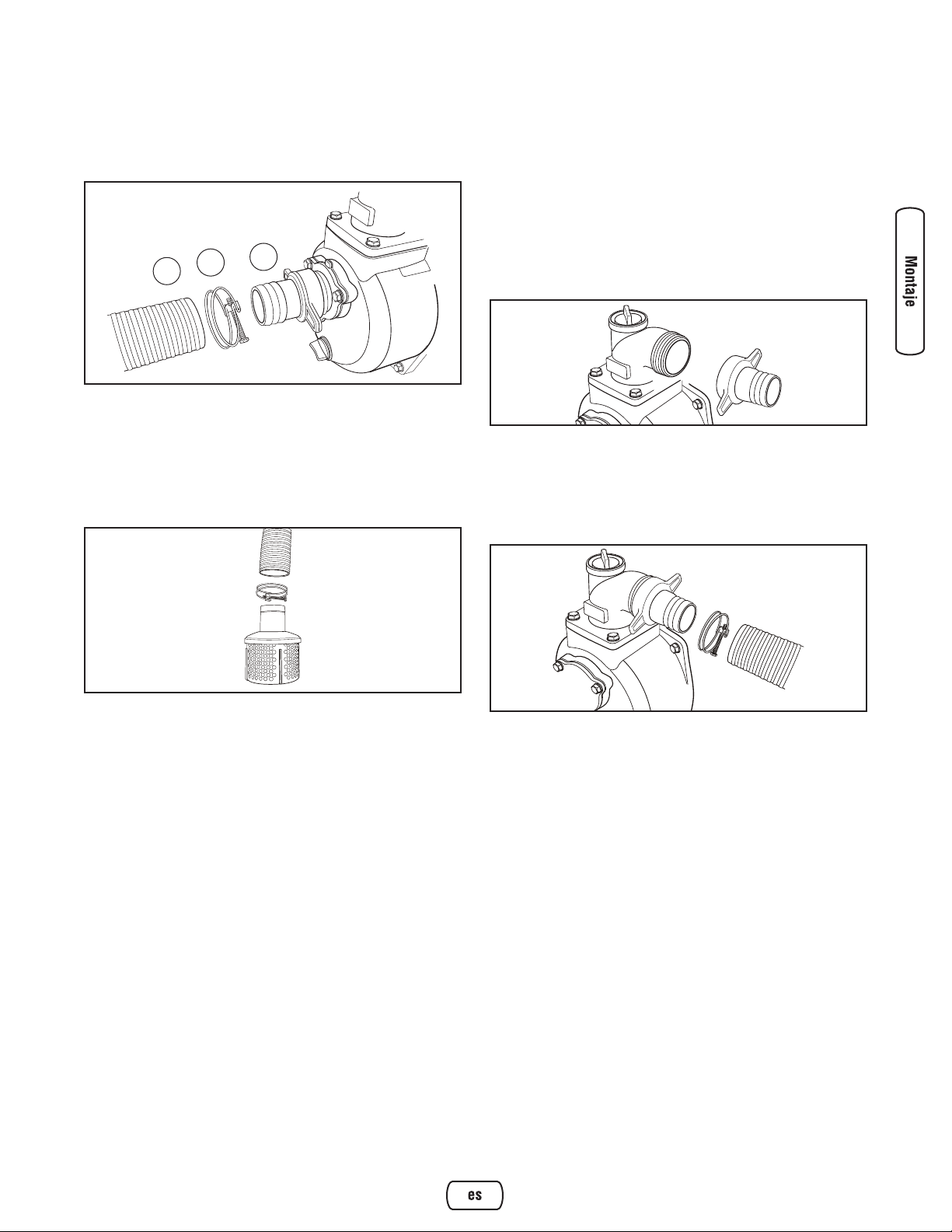
3. Introduzca el extremo de la manguera (B) en la
abrazadera de la manguera (A). Introduzca la manguera
de aspiración en el conector de la manguera (C).
Apriete firmemente la abrazadera con un destornillador
normal de 1/4" (6 mm).
Conexión de la manguera a la cesta del filtro
Introduzca la manguera en la abrazadera de la manguera.
Conecte el extremo abierto de la manguera de aspiración en
el conector de la manguera del filtro. Apriete firmemente la
abrazadera con un destornillador normal de 1/4" (6 mm).
Conexión de la manguera de descarga (opcional)
Si lo desea, utilice una manguera adquirida en un
establecimiento comercial. NO utilice una manguera cuyo
diámetro interior sea inferior al del orificio de descarga de la
bomba.
1. Introduzca el conector de la manguera por el puño del
conector. Inserte la junta de goma en el extremo del
puño del conector como se ha mostrado anteriormente.
2. Enrosque el conjunto del conector de la manguera en la
bomba hasta apretarlo firmemente.
3. Introduzca el extremo de la manguera de descarga en la
abrazadera de la manguera. Introduzca la manguera de
descarga en el conector de la manguera. Apriete
firmemente la abrazadera con un destornillador normal
de 1/4" (6 mm).
9
Español
C
A
B
Page 34

10 BRIGGSandSTRATTON.COM
A - Depósito de combustible — Llene el tanque con
gasolina regular sin contenido de plomo en este punto.
Siempre habitación de hoja para la expansión del
combustible.
B - Tapón de cebado — Permite llenar la bomba de
transferencia de agua para cebarla antes de la puesta en
marcha.
C - Salida de descarga — Conecte aquí la manguera de
descarga.
D - Palanca estranguladora — Se utiliza para arrancar un
motor en frío.
E - Filtro de aire — Protege el motor filtrando el polvo y los
residuos del aire de admisión.
F - Arrancador de retroceso — Permite arrancar el motor.
G - Palanca del acelerador — Permite regular la velocidad
del motor para controlar el rendimiento de la bomba.
H - Interruptor On/Off — Sitúe el interruptor en la posición
"On" antes de utilizar el arrancador de retroceso. Sitúelo
en la posición "Off" para parar el motor.
J - Tapón de Vaciado de Aceite — Permite vaciar el aceite
del motor.
K - Tapón de aceite — Permite comprobar el nivel de aceite
y llenar el motor.
L - Etiqueta de datos — Indica los números de modelo,
revisión y serie de la bomba de transferencia de agua.
Tenga esta información preparada si llama al servicio
técnico.
M - Entrada de aspiración — Conecte aquí la manguera de
aspiración reforzada.
N - Tapón de vaciado de agua — Permite vaciar el agua de
la bomba y limpiar los componentes internos con agua
limpia.
P - Cámara de la bomba — Asegúrese de llenarla de agua
antes de la puesta en marcha.
R - Información de motor — Estampado en la cubierta de
válvula. Indica los números de modelo, tipo y códiga de
la motor. Tenga esta información preparada si llama al
servicio técnico.
S - Válvula de paso de combustible — Permite abrir y
cerrar la alimentación de combustible al motor.
No mostrado:
Cesta del filtro — Utilizado para limitar el pasaje de
materias abrasivas en la bomba.
Características y mandos
Lea el Manual del Operario y las reglas de seguridad antes de poner en marcha su máquina bomba de
transferencia de agua. Compare las ilustraciones con su máquina bomba de transferencia de agua para familiarizarse
con las ubicaciones de los diferentes controles y ajustes. Guarde este manual para referencias futuras.
G
E
J
F
K
D
H L M N P S
CBA
R
Page 35
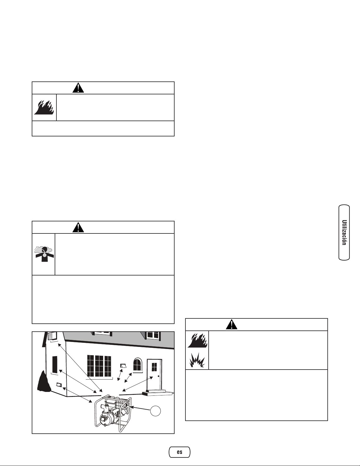
Operando
Si tiene problemas operando su bomba de transferencia de
agua, por favor llame a la línea de ayuda para máquinas
bomba de transferencia de agua al (800) 743-4115.
Consideraciones para un uso seguro
Espacio libre y circulación de aire
Coloque la bomba de transferencia de agua a la intemperie en
una zona en donde no se acumulen gases de escape mortales.
NO instale el bomba de transferencia de agua en lugares en
los que los gases de escape (A) se puedan acumular o entrar
en un edificio que pueda estar ocupado. Asegúrese de que los
gases de escape no puedan entrar por ventanas, puertas,
tomas de aire de ventilación u otras aberturas en un espacio
cerrado en el que puedan acumularse. Tenga en cuenta los
vientos y las corriente de aire preponderantes cuando elija la
ubicación del bomba de transferencia de agua.
¿Qué es la "altura total"?
La altura total es la altura de la columna de agua que puede
generar la descarga de la bomba.
La altura de aspiración es la distancia vertical entre el centro
de la bomba y la superficie del líquido en el lado de la
succión de la bomba. Se puede referir también a como
“ascensor de succión”. La presión atmosférica de 14,7 psi
en nivel del mar limita la succión ascensor de cabeza a
menos que aproximadamente 26 pies para cualquier bomba.
La altura de descarga es la distancia vertical entre el puerto
de la descarga de bomba y el punto de la descarga, que es la
superficie líquida si la manga se sumerge o bombeando en el
fondo de un tanque.
La altura total es la suma del valor de cabeza de succión más
el valor de cabeza de descarga.
A medida que aumenta la altura del bombeo de agua, se
reduce el rendimiento de la bomba. La longitud, el tipo y el
tamaño de las mangueras de aspiración y descarga también
pueden afectar en gran medida al rendimiento de la bomba.
La capacidad de descarga de agua es siempre superior a la
de aspiración, por lo que es importante que la aspiración sea
la parte más corta de la acción de bombeo. Esto reducirá el
tiempo de cebado y mejorará el rendimiento de la bomba
aumentando la altura total de descarga.
La altura máxima de aspiración es de 8 m (25 pies), y la
altura máxima de descarga, de 25 m (81 pies). La altura total
no puede superar 32 m (106 pies) (página siguiente).
Colocación de la bomba de transferencia de
agua en una posición segura
Para mejorar el rendimiento de la bomba, ubíquela en una
superficie plana y nivelada, lo más cerca posible del agua
bombeada. Asegure la bomba de transferencia de agua para
impedir su caída. No utilice mangueras más largas de lo
necesario.
IMPORTANTE: No dirija el extremo abierto de la manguera
de descarga hacia edificios, aparatos eléctricos u otros
elementos que no desee mojar.
11
Español
ADVERTENCIA
Los gases y el calor de escape pueden inflamar
los materiales combustibles y las estructuras o
dañar el depósito de combustible y provocar un
incendio.
• Deje un espacio mínimo de 152 cm (5 pies) alrededor del
bomba de transferencia de agua, incluida la parte superior.
ADVERTENCIA
Al motor funcionar, se produce monóxido de
carbono, un gas inodoro y venenoso.
Respirar monóxido de carbono puede provocar
dolor de cabeza, fatiga, mareos, vómitos,
confusión, ataques, náuseas, desmayos o incluso
la muerte.
• Opere el bomba de transferencia de agua SOLAMENTE al aire
libre.
• Asegúrese de que los gases de escape no puedan entrar por
ventanas, puertas, tomas de aire de ventilación u otras aberturas
en un espacio cerrado en el que puedan acumularse.
• NO arranque ni deje funcionar el motor en interiores ni en zonas
cerradas, aunque haya ventanas y puertas abiertas.
ADVERTENCIA
La gasolina y sus vapores son extremadamente
inflamables y explosivos.
El fuego o una explosión pueden causar
quemaduras severas e inclusive la muerte.
CUANDO OPERE EL EQUIPO
• Este bomba de transferencia de agua no es apto para el uso en
equipos móviles ni en aplicaciones marinas.
• NO incline el motor ni el equipo de forma que pueda derramarse
el combustible.
• Asegure la bomba de transferencia de agua. Las cargas de las
mangueras pueden provocar la caída de la bomba.
A
Page 36
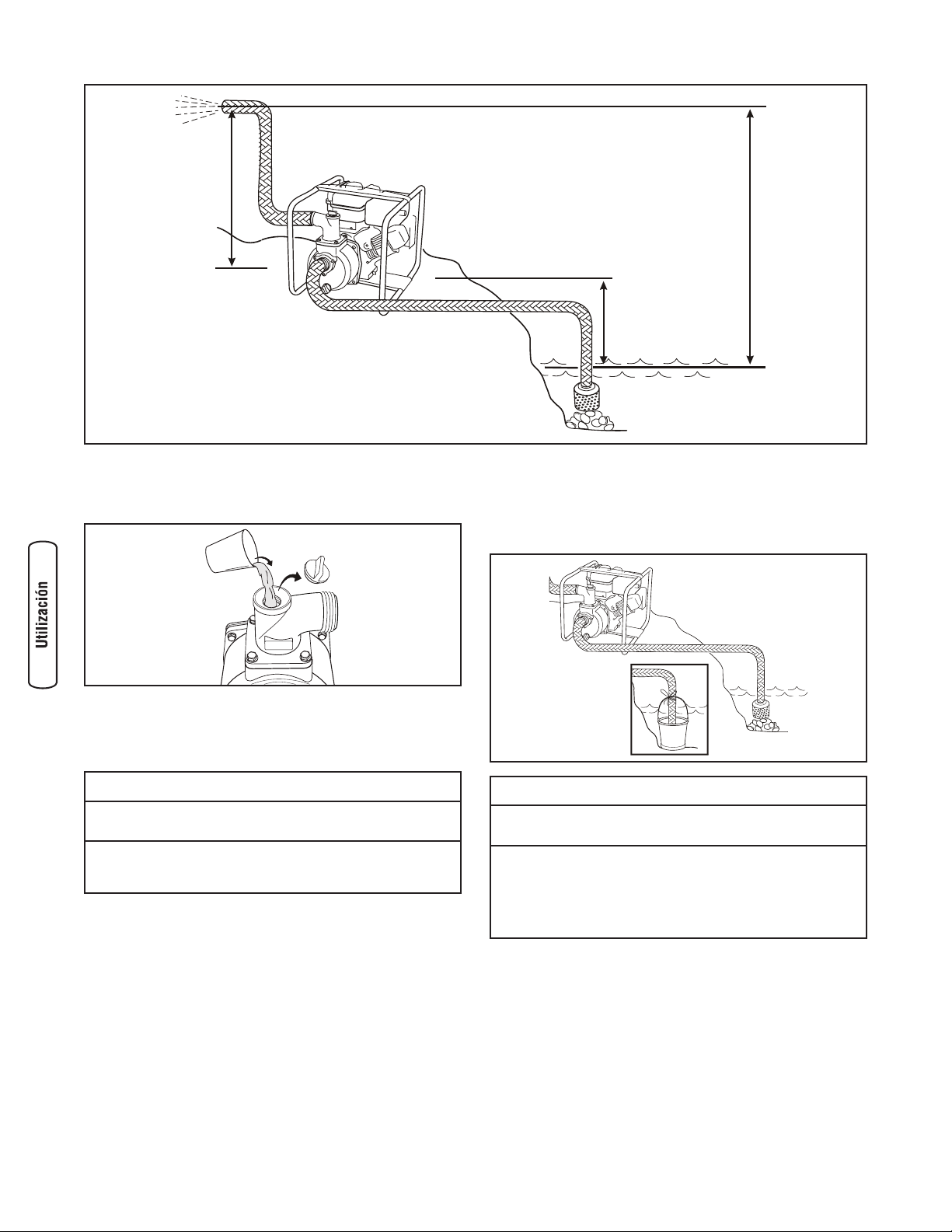
Cebado de la bomba de transferencia de agua
1. Quite el tapón de la parte superior de la bomba.
2. Llene la bomba con agua limpia y clara hasta la parte
superior del orificio de descarga.
3. Vuelva a colocar el tapón de la bomba.
Colocación de la cesta del filtro en la fuente de
agua
Coloque la cesta del filtro en el agua de bombeo. La cesta
debe quedar totalmente sumergida.
12 BRIGGSandSTRATTON.COM
Bomba de transferencia de agua habitual
Altura de descarga
- 25 m (81 pies) máx
Altura de aspiración
- 8 m (25 pies) máx
Altura total
- 32 m (106 pies) máx
AVISO
El tratamiento inadecuado del bomba de transferencia de
agua puede dañarlo y acortar su vida productiva.
• Asegúrese de que la cámara de la bomba esté llena de agua
antes de arrancar el motor. NUNCA utilice la bomba sin cebarla
previamente.
AVISO
El tratamiento inadecuado del bomba de transferencia de
agua puede dañarlo y acortar su vida productiva.
• NUNCA utilice la bomba sin un filtro en el extremo de la
manguera de aspiración.
• Evite el contacto del filtro con la arena o el cieno, colóquelo en
un cubo o sobre unas piedras.
• EVITE que la bomba funcione en seco para no dañar las juntas.
Page 37

Puesta en marcha de la bomba de transferencia
de agua
Siga las siguientes instrucciones de puesta en marcha:
1. Asegúrese de que la unidad está ubicada en una
superficie plana y nivelada y de que la cámara se ha
cebado.
2. Sitúe la válvula de combustible (A) en la posición "On".
El tirador de la válvula de combustible quedará en
posición vertical, apuntando hacia el suelo.
3. Sitúe el interruptor on/off (B) en la posición "On".
4. Mueva la palanca del acelerador (C) hasta la posición
"Rápido" ( ).
5. Mueva la palanca estranguladora (D) hasta la posición
"Estrangular" ( ).
6. Agarre el asa del arrancador de retroceso y tire
lentamente hasta notar una ligera resistencia. A
continuación, tire rápidamente del asa para vencer la
compresión, evitar el retroceso y arrancar.
IMPORTANTE: Si el motor se ahoga, sitúe la palanca
estranguladora en la posición "Funcionamiento" ( ) y tire
del asa repetidamente hasta que el motor arranque.
7. Mueva poco a poco la palanca estranguladora hacia la
posición "Funcionamiento" ( ) a intervalos de
segundos (tiempo cálido) o minutos (tiempo frío).
Espere a que el motor funcione suavemente antes de
cada cambio. Utilice la bomba con la palanca
estranguladora en la posición "Funcionamiento" ( ).
IMPORTANTE: La bomba puede necesitar que transcurran
varios minutos para empezar a bombear agua.
El rendimiento de la bomba se controla regulando la
velocidad del motor. Mueva la palanca de velocidad del
motor hacia la posición "Rápido" ( ) para aumentar el
rendimiento del motor. Si la mueve hacia la posición
"Lento" ( ), reducirá el rendimiento del motor.
13
Español
A
B
C
D
ADVERTENCIA
El retroceso (repliegue rápido) del cable del
arrancador puede producir lesiones. El retroceso
impedirá que el usuario suelte el cable a tiempo y
tirará de su mano y brazo hacia el motor.
Como resultado, podrían producirse fracturas,
contusiones o esguinces.
• Cuando arranque el motor, tire lentamente del cable hasta sentir
una resistencia y, a continuación, tire rápidamente de él para
evitar su retroceso.
ADVERTENCIA
El contacto con la zona del silenciador puede
producir quemaduras graves.
Los gases y el calor de escape pueden inflamar
los materiales combustibles y las estructuras o
dañar el depósito de combustible y provocar un
incendio.
• NO toque las superficies calientes y EVITE los gases del escape
a alta temperatura.
• Permita que el equipo se enfríe antes de tocarlo.
• Deje un espacio mínimo de 1.5 m (5 pies) alrededor del bomba
de transferencia de agua, incluida la parte superior.
• El Código de Normativa Federal (CFR, Título 36: Parques,
Bosques y Propiedad Pública) obliga a instalar una pantalla
apagachispas en los equipos con motor de combustión interno
y a mantenerla en buenas condiciones de funcionamiento,
conforme a la norma 5100-1C (o posterior) del Servicio Forestal
de la USDA. En el Estado de California, la ley exige el uso de una
pantalla apagachispas (Sección 4442 del Código de Recursos
Públicos de California). En otros estados puede haber leyes
similares en vigor.
Page 38
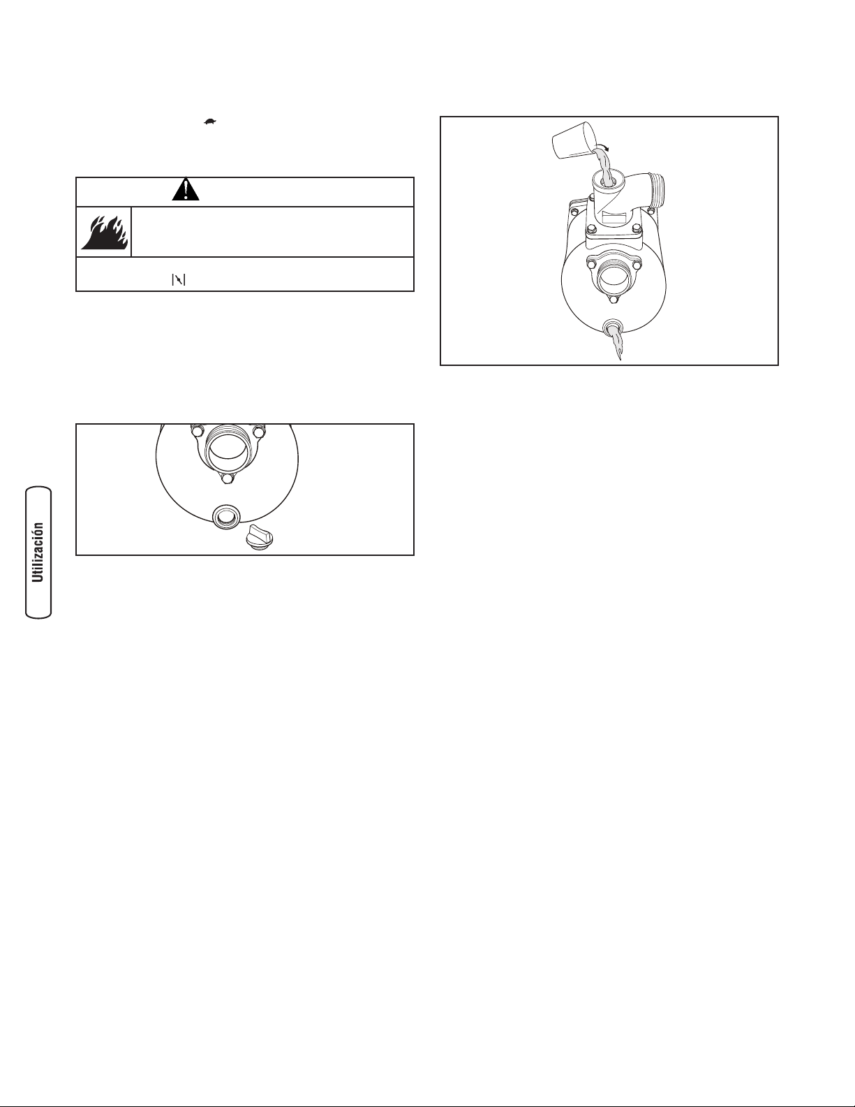
Parada de la bomba de transferencia de agua
1. Mueva la palanca de velocidad del motor hasta la
posición "Lento" ( ).
2. Sitúe el interruptor on/off en la posición "Off".
3. Gire la válvula de combustible hasta la posición "Off".
Vaciado y limpieza de la bomba de transferencia
de agua
1. Desconecte y vacíe las mangueras de aspiración y
descarga.
2. Quite el tapón de vaciado, situado en la parte inferior
de la bomba.
3. Quite el tapón de la parte superior de la bomba y lave
los componentes internos con agua limpia.
4. Vuelva a colocar ambos tapones y apriételos con
la mano.
14 BRIGGSandSTRATTON.COM
ADVERTENCIA
El motor podría petardear, incendiarse o dañarse.
• NO coloque la palanca estranguladora en la posición
"
Estrangular" ( ) para parar el motor.
Page 39
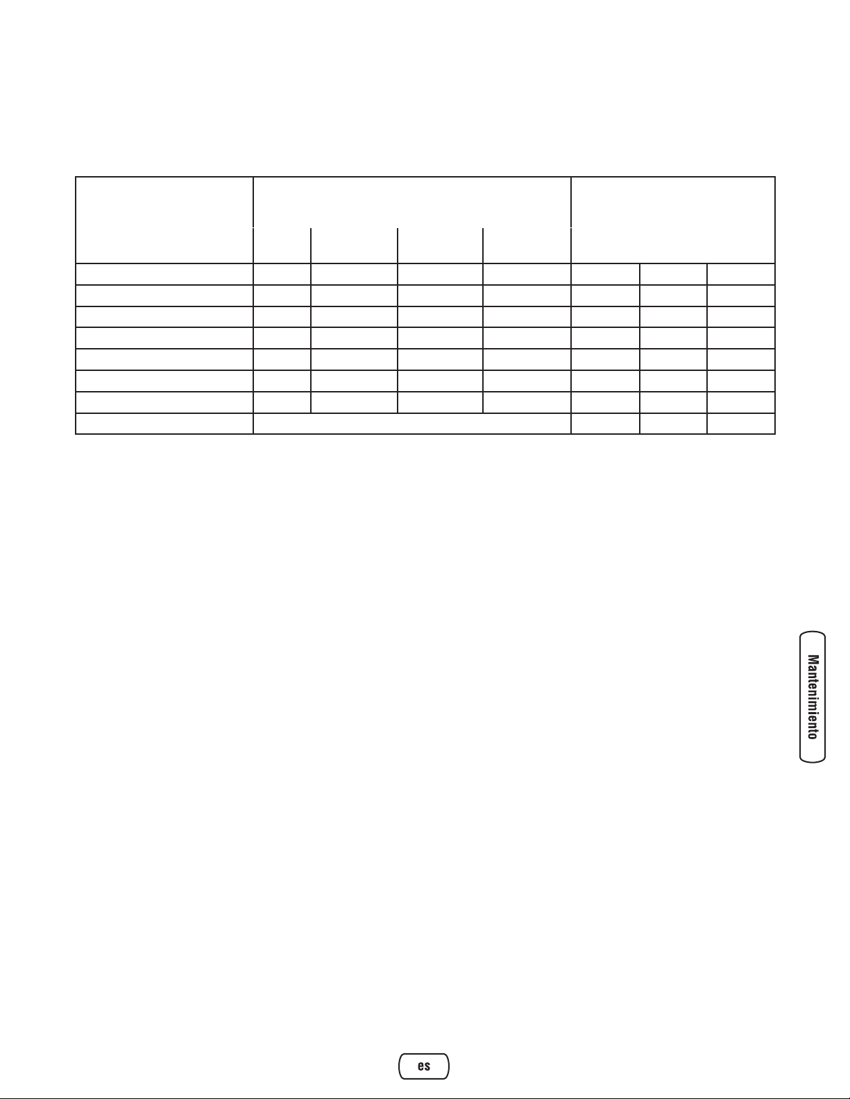
15
Español
Mantenimiento
Plan de mantenimiento
Observe los intervalos de horas o de calendario, lo que suceda antes. Se requiere un mantenimiento más frecuente al operar
en condiciones adversas como se indica a continuación.
¹ Cambie el aceite después de las primeras 5 horas de funcionamiento y, en lo sucesivo, cada 50 horas o una vez al año, lo que suceda antes.
Cámbielo antes si el motor funciona en condiciones de suciedad o polvo.
² Sustitúyalo con más frecuencia en condiciones de suciedad o polvo.
TAREA DE MANTENIMIENTO
FECHAS DE MANTENIMIENTO
FECHAS DE MANTENIMIENTO
Antes de
cada uso
Cada 25 horas o
una vez al año
Cada 50 horas o
una vez al año
Cada 100 horas o
una vez al año
Limpie los residuos
X
Compruebe el nivel de aceite
X
Cambie el aceite del motor
X¹
Revise el filtro de aire
X²
Revise la bujía
X
Revise el apagachispas
X
Limpie el sistema de refrigeración
X²
Prepare el almacenamiento Si la unidad no se va a utilizar durante 30 o más días.
Recomendaciones generales
El mantenimiento periódico mejorará el rendimiento y
prolongará la vida útil de la bomba de transferencia de agua.
Acuda a un distribuidor autorizado de Briggs & Stratton para
reparar la unidad.
La garantía de la bomba de transferencia de agua no cubre
los elementos sujetos a un uso indebido o negligente. Para
hacer valer la garantía, el usuario deberá mantener la bomba
conforme a las instrucciones de este manual.
Para mantener la bomba de transferencia de agua en buen
estado, será necesario realizar algunos ajustes
periódicamente.
La totalidad de las reparaciones y los ajustes se deberán
realizar al menos una vez por temporada. Siga las
indicaciones del cuadro Plan de mantenimiento.
NOTA: Limpie o cambie la bujía y cambie el filtro de aire una
vez al año. Una bujía nueva y un filtro de aire limpio
aseguran la mezcla adecuada de combustible y aire y
contribuyen a mejorar el rendimiento del motor y a prolongar
su vida útil.
Control de emisiones
Cualquier establecimiento o individuo especializado en la
reparación de motores que no sean de automoción puede
encargarse del mantenimiento, la sustitución y la
reparación de los dispositivos y sistemas de control de
emisiones. No obstante, para realizar la revisión gratuita de
control de emisiones, deberá acudir a un distribuidor
autorizado por el fabricante. Véase Garantía de emisiones.
Mantenimiento del bomba de transferencia
de agua
El mantenimiento consiste en mantener limpia la bomba de
transferencia de agua. Guarde la unidad en un espacio limpio
y seco, sin exceso de polvo, suciedad, humedad y vapores
corrosivos. Las ranuras del aire de refrigeración del motor
de la bomba de transferencia de agua no deben quedar
obstruidas por hojas ni por ningún otro tipo de suciedad o
material.
NOTA: NO utilice una manguera de jardinería para limpiar el
motor de la bomba. Podría entrar agua en el conducto de
combustible y causar problemas.
Page 40
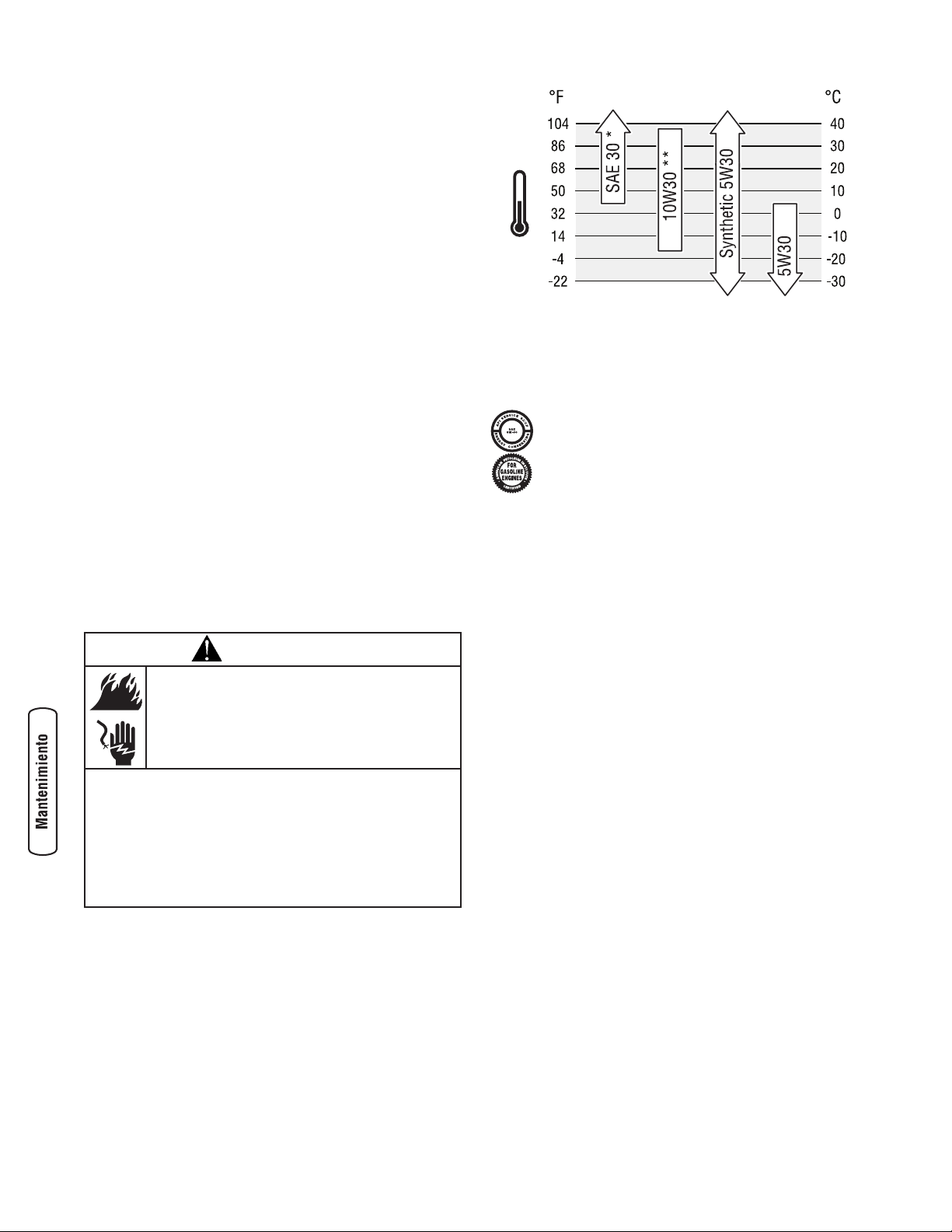
Limpieza
Cada día, o antes de cada uso, examine la parte de alrededor y
de debajo de la bomba en busca de signos de pérdida de
aceite o combustible. Limpie los residuos acumulados en el
interior y el exterior de la bomba. Mantenga limpias las
conexiones, los muelles y los mandos del motor. Elimine los
restos de combustible de la zona de alrededor y de encima del
silenciador. Utilice aire a baja presión (no superior a 25 psi)
para eliminar la suciedad. Inspeccione las ranuras y aberturas
de aire de refrigeración de la bomba de transferencia de agua.
Las aberturas deben estar limpias y despejadas.
Mantenga limpios los componentes del motor para reducir el
riesgo de sobrecalentamiento e ignición de los residuos
acumulados.
• Utilice un trapo húmedo para limpiar las superficies
exteriores.
• Utilice un cepillo de cerda suave para eliminar los
restos de suciedad o aceite endurecidos.
• Utilice una aspiradora para eliminar los restos sueltos
de suciedad.
Elimine toda acumulación de cieno y sedimentos del cuerpo
de la bomba.
• Abra el tapón de cebado y retire el tapón de vaciado.
• Lave los componentes internos de la bomba con agua
limpia.
Mantenimiento del motor
Aceite
Recomendaciones sobre el aceite
Para obtener el mejor rendimiento, recomendamos utilizar
aceites certificados con garantía Briggs & Stratton. También
se pueden utilizar otros aceites detergentes de alta calidad
con clasificación de servicio SF, SG, SH, SJ o superior. NO
utilice aditivos especiales.
Las temperaturas exteriores determinan la viscosidad
adecuada del aceite para el motor. Utilice el cuadro para
seleccionar la mejor viscosidad para el intervalo de
temperatura exterior previsto.
* Por debajo de 4 °C (40 °F), el uso de aceite SAE 30 provocará
dificultades de arranque.
** Por encima de 27 °C (80 °F) el uso de aceite 10W30 puede
aumentar el consumo de aceite. Compruebe el nivel de aceite
con mayor frecuencia.
NOTA: Todo aceite sintético que cumpla las
especificaciones ILSAC GF-2, con marca de
certificación API y con símbolo de servicio API (se
muestra a la izquierda) con “SJ/CF ENERGY
CONSERVING” o superior es un aceite aceptable a
todas las temperaturas. El uso de aceite sintético no
altera los intervalos de cambio de aceite indicados.
Comprobación del nivel de aceite
Compruebe el nivel de aceite antes de cada uso o cada
5 horas de funcionamiento, como mínimo. Rellene si es
necesario.
1. Coloque el bomba de transferencia de agua sobre una
superficie nivelada.
2. Quite el tapón de llenado de aceite y límpielo con un
trapo.
3. Compruebe que el aceite llega hasta el punto de
desbordamiento en el orificio de llenado.
4. Instale el tapón de llenado de aceite, apriete
firmemente.
Adición de Aceite del Motor
1. Coloque el bomba de transferencia de agua sobre una
superficie nivelada.
2. Compruebe el nivel de aceite tal como se indica en la
sección Comprobación del nivel de aceite.
3. Si es necesario, vierta lentamente aceite por el orificio
de llenado hasta el punto de desbordamiento en el
tapón de llenado de aceite.
4. Instale el tapón de llenado de aceite, apriete
firmemente.
16 BRIGGSandSTRATTON.COM
ADVERTENCIA
Chispear involuntario puede tener como
resultado el fuego o el golpe eléctrico.
CUANDO AJUSTE O HAGA REPARACIONES A SU MÁQUINA
BOMBA DE TRANSFERENCIA DE AGUA
• Siempre desconecte el alambre de la bujía y colóquelo donde no
pueda entrar en contacto con la bujía.
CUANDO PRUEBE LA BUJÍA DEL MOTOR
• Utilice un comprobador de bujías homologado.
• NO comprueba la chispa sin la bujía instalada.
Page 41
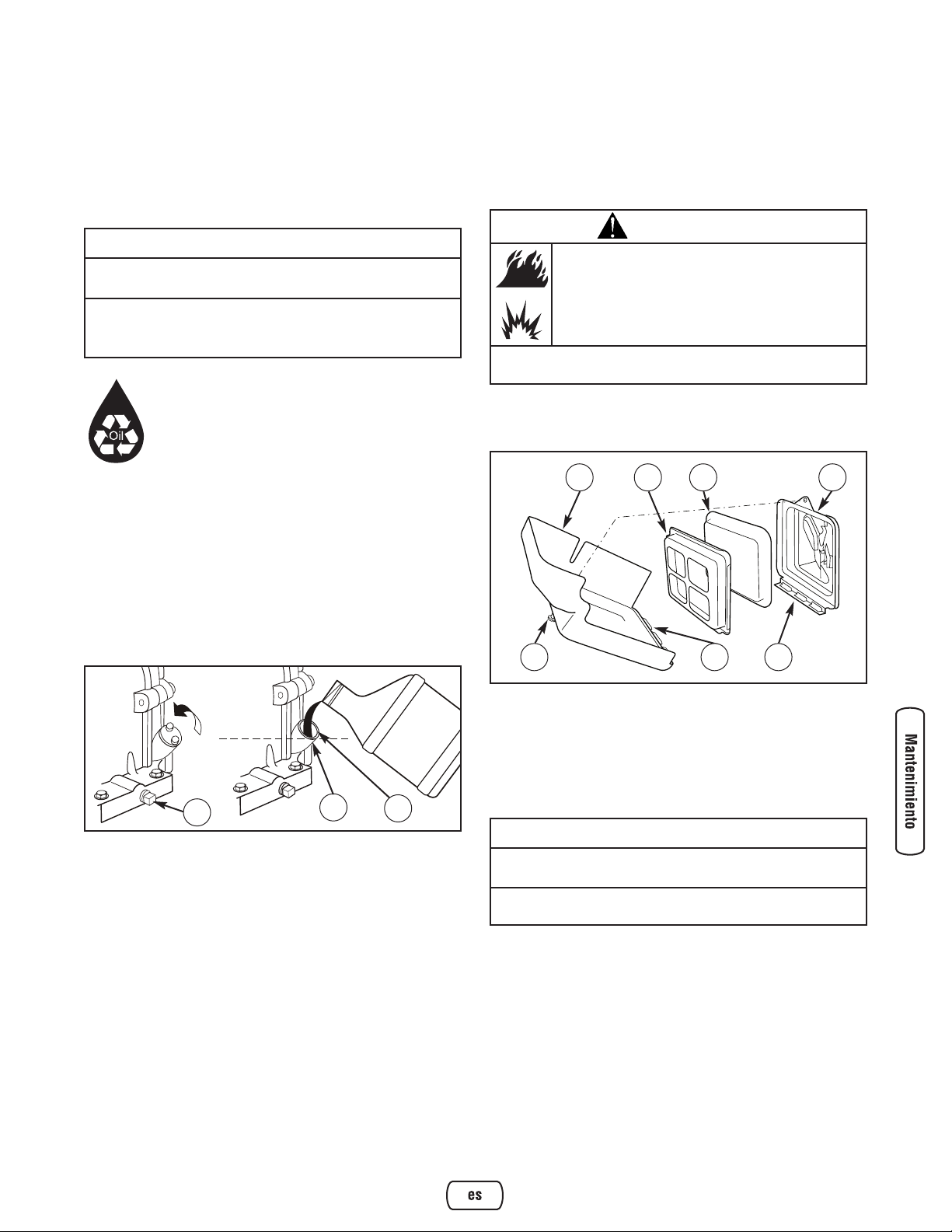
17
Español
Cambio de aceite del motor
Cambie el aceite después de las primeras 5 horas de
operación. Cambie el aceite cada 50 horas de ese momento
en adelante. Si está utilizando su bomba de transferencia de
agua bajo condiciones de extrema suciedad o polvo, o en un
clima demasiado caliente, haga el cambio de aceite más
frecuentemente.
MANTENER FUERA DEL ALCANCE DE LOS NIÑOS.
NO CONTAMINE. CONSERVE LOS RECURSOS.
DEPOSITE EL ACEITE USADO EN UN PUNTO DE
RECOGIDA.
Cambie el aceite cuando el motor siga estando caliente
después de haber funcionado:
1. Asegúrese de que la unidad esté en una superficie
plana.
2. Desconecte el cable de la bujía de esta y colóquelo
donde no pueda entrar en contacto con la bujía.
3. Limpie la zona de alrededor del tapón de vaciado de
aceite (A), situado en la base del motor, al otro lado del
carburador.
4. Quite el tapón de llenado de aceite y vacíe todo el aceite
en un recipiente adecuado.
5. Vuelva a colocar el tapón de vaciado y apriételo bien.
Quite el tapón de llenado de aceite.
6. Vierta lentamente unos 0,6 litros (20 onzas) de aceite
por el orificio de llenado (B) hasta el punto de
desbordamiento (C). NO añada aceite en exceso.
7. Vuelva a colocar el tapón de llenado de aceite. Apriételo
firmemente a mano.
8. Limpie los residuos de aceite.
Revisión del filtro de aire
Si se utiliza con un filtro de aire sucio, el motor no
funcionará correctamente y puede sufrir daños.
Cambie el filtro de aire cada 25 horas de funcionamiento o
una vez al año, lo que suceda antes. Haga cambios más
frecuentes si trabaja en zonas sucias o donde hay polvo.
Para revisar el filtro de aire, siga estos pasos:
1. Afloje el tornillo (D) y quite la cubierta (E).
2. Quite el conjunto del filtro de aire de la tapa.
3. Separe con cuidado el filtro de aire de espuma (F) de la
placa del filtro de aire (G).
4. Lave el filtro de aire de espuma en detergente líquido y
agua. Para secarlo, escúrralo en un trapo limpio.
5. Empape el filtro de aire de espuma en aceite de motor
limpio. Para eliminar el exceso de aceite, escúrralo en
un trapo limpio.
6. Vuelva a montar el filtro de aire de espuma limpio y
empapado en aceite en la placa del filtro de aire.
7. Encaje bien el conjunto del filtro de aire en la tapa.
8. Inserte las lengüetas (H) de la cubierta en las ranuras (J)
que se encuentran en el fondo de la base (K).
9. Coloque la cubierta en su lugar y apriete el tornillo
firmemente a la base.
A
B
C
AVISO
Evite el contacto prolongado o repetido de piel con aceite
usado de motor.
• El aceite usado del motor ha sido mostrado al cancer de la piel
de la causa en ciertos animales del laboratorio.
• Completamente lavado expuso áreas con el jabón y el agua.
AVISO
NO utilice aire comprimido ni disolventes para limpiar el
filtro de aire de espuma.
• El aire comprimido puede dañar el filtro de aire de espuma, y los
disolventes lo disolverían.
ADVERTENCIA
La gasolina y sus vapores son extremadamente
inflamables y explosivos.
El fuego o una explosión pueden causar
quemaduras severas e inclusive la muerte.
• NUNCA arranque ni deje funcionar el motor sin el conjunto del
filtro de aire o sin el filtro de aire de espuma.
F
D
E
H
G K
J
Page 42

Revisión de la bujía
Cambie la bujía cada 100 horas de funcionamiento o una vez
al año, lo que suceda antes. Esta operación hará que el
motor arranque más fácilmente y funcione mejor.
1. Limpie la zona de alrededor de la bujía.
2. Retire e inspeccione la bujía.
3. Revise la separación del electrodo con un calibrador de
alambre y ajuste la separación a 0.030 pulgadas
(0.76 mm) si es necesario.
4. Cambie la bujía si los electrodos están picados o
quemados o si la porcelana está agrietada. Utilice la
bujía de repuesto recomendada. Consulte
Especificaciones.
5. Instale la bujía y apriete firmemente.
Limpieza de la pantalla apagachispas
El silenciador del escape del motor puede estar equipado con
una pantalla apagachispas. Si es así, inspeccione y limpie la
pantalla cada 50 horas de funcionamiento o una vez al año,
lo que suceda primero.
Si utiliza la bomba de transferencia de agua en un terreno
boscoso, con maleza o cubierto de hierba, debe utilizar un
apagachispas. El propietario y el usuario son responsables
del buen estado del mismo.
Si el motor ha estado en funcionamiento, la temperatura del
silenciador será muy elevada. Deje enfriar el silenciador
antes de realizar ninguna operación en el apagachispas.
1. Retire la pantalla del apagachispas para proceder a su
limpieza e inspección.
2. Examine la pantalla y cámbiela si está rota o perforada
o si presenta algún otro daño. NO utilice una pantalla
que no esté en perfectas condiciones. Si la pantalla no
presenta daños, límpiela con un disolvente comercial.
3. Vuelva a montar la pantalla apagachispas en el
silenciador.
NOTA: Puede adquirir una nueva pantalla apagachispas
contacte su local centro de reparaciones de Briggs &
Stratton.
Sistema de refrigeración de aire
Con el tiempo, se pueden acumular residuos en las aletas de
refrigeración del cilindro y pasar inadvertidos mientras no se
desmonte parcialmente el motor. Recomendamos que
encargue la limpieza del sistema de refrigeración a un
distribuidor autorizado de Briggs & Stratton siguiendo los
intervalos recomendados (consulte la sección Plan de
Mantenimiento en la sección Mantenimiento). Es igualmente
importante que no se acumulen residuos en la parte superior
del motor ni en la pantalla giratoria. Consulte la sección
Limpieza.
Almacenamiento
La bomba de transferencia de agua debe funcionar durante
un mínimo de 30 minutos cada siete días, como mínimo. Si
esta operación no es posible y necesita almacenar la unidad
durante más de 30 días, utilice la siguiente información para
prepararla.
Instrucciones de almacenamiento a largo plazo
Durante el almacenamiento, es importante evitar la formación
de residuos en los componentes esenciales del circuito de
combustible: carburador, filtro de combustible, manguera de
combustible y depósito. La experiencia también indica que
los combustibles con mezcla de alcohol (gasohol, etanol o
metanol) pueden atraer la humedad y provocar la separación
y formación de ácidos durante el almacenamiento. Los
combustibles ácidos pueden dañar el circuito de combustible
y el motor durante el almacenamiento.
18 BRIGGSandSTRATTON.COM
ADVERTENCIA
El contacto con la zona del silenciador puede
producir quemaduras graves.
Los gases y el calor de escape pueden inflamar
los materiales combustibles y las estructuras o
dañar el depósito de combustible y provocar un
incendio.
• NO toque las superficies calientes y EVITE los gases del escape
a alta temperatura.
• Permita que el equipo se enfríe antes de tocarlo.
• Deje un espacio mínimo de 1.5 m (5 pies) alrededor del bomba
de transferencia de agua, incluida la parte superior.
• El Código de Normativa Federal (CFR, Título 36: Parques,
Bosques y Propiedad Pública) obliga a instalar una pantalla
apagachispas en los equipos con motor de combustión interno
y a mantenerla en buenas condiciones de funcionamiento,
conforme a la norma 5100-1C (o posterior) del Servicio Forestal
de la USDA. En el Estado de California, la ley exige el uso de una
pantalla apagachispas (Sección 4442 del Código de Recursos
Públicos de California). En otros estados puede haber leyes
similares en vigor.
Page 43

19
Español
Proteja el sistema de combustible
Aditivo para combustible:
El combustible puede estar pasado 30 días después de su
almacenamiento. El combustible pasado provoca la
formación de residuos ácidos y de carbonilla en el circuito
de combustible y en los componentes básicos del
carburador. Para mantener el combustible en buen estado,
utilice el estabilizador de combustible FRESH START™ de
Briggs & Stratton en cualquiera de sus variantes: líquido o
cartucho concentrado con goteo.
Si se añade un estabilizador de combustible conforme a las
instrucciones, no será necesario vaciar el motor de
combustible. Haga funcionar el motor durante dos minutos
para que el estabilizador circule por todo el circuito de
combustible. El motor y el combustible se pueden almacenar
hasta 24 meses.
Si no se ha añadido un estabilizador de combustible a la
gasolina, deberá vaciar completamente el motor utilizando
un contenedor homologado. Deje funcionar el motor hasta
que se agote el combustible. Se recomienda utilizar un
estabilizador de combustible en el contenedor de
almacenamiento para mantener la gasolina en buen estado.
Cambio de aceite del motor
Con el motor todavía caliente, drene el aceite de la caja del
cigüeñal. Vuelva a llenarlo con el grado de aceite
recomendado. Vea Cambio de Aceite del Motor en la sección
Mantenimiento del Motor.
Aceite el diámetro interior del cilindro
• Quite la bujía y vierta aproximadamente 15 ml
(1/2 onza) de aceite de motor limpio en el interior del
cilindro.
• Coloque la bujía y arranque lentamente para distribuir el
aceite.
Bomba de transferencia de agua
1. Vacíe la bomba de transferencia de agua tal como se
indica en la sección Vaciado y limpieza de la bomba de
transferencia de agua.
2. Limpie la bomba de transferencia de agua según se
describe en Limpieza.
3. Compruebe que las aberturas de la bomba de
transferencia de agua estén abiertas y despejadas.
Otras sugerencias para el almacenamiento
1. NO guarde combustible de una temporada a otra a
menos que lo haya tratado como se indica en la
sección Aditivo para combustible.
2. Reemplace la caneca de gasolina si comienza a
oxidarse. El óxido y/o la suciedad en la gasolina le
causará problemas.
3. Cubra la unidad con una funda adecuada que no
retenga la humedad.
4. Almacene la bomba de transferencia de agua en una
zona limpia y seca.
ADVERTENCIA
La gasolina y sus vapores son extremadamente
inflamables y explosivos.
El fuego o una explosión pueden causar
quemaduras severas e inclusive la muerte.
CUANDO ALMACENE O GUARDE EL EQUIPO CON COMBUSTIBLE
EN EL TANQUE
• Almacene alejado de calderas, estufas, calentadores de agua,
secadoras de ropa u otros aparatos electrodomésticos que
posean pilotos u otras fuentes de ignición, porque ellos pueden
encender los vapores de la combustible.
CUANDO VACÍE EL DEPÓSITO
• Apague el bomba de transferencia de agua (posición OFF) y déjelo
enfriar al menos por 2 minutos antes de remover la tapa de la
combustible. Afloje la tapa lentamente para dejar que la presión
salga del tanque.
• Vacíe el depósito de combustible a la intemperie.
• Mantenga la gasolina alejada de chispas, llamas abiertas,
pilotos, calor y otras fuentes de ignición.
• NO encienda un cigarrillo o fume.
ADVERTENCIA
Chispear involuntario puede tener como
resultado el fuego o el golpe eléctrico.
• NUNCA tire del asa del arrancador cuando la bujía no esté
instalada.
ADVERTENCIA
Las cubiertas para almacenamiento pueden ser
inflamables.
• NO coloque una cubierta encima de un bomba de transferencia
de agua caliente.
• Deje que la unidad se enfríe lo suficientemente antes de que le
coloque la cubierta.
Page 44

20 BRIGGSandSTRATTON.COM
Resolución de Problemas
Problema Motivo Solución
La bomba funciona pero
descarga poca o ningún
agua.
1. La bomba no se ha cebado.
2. La manguera de aspiración está doblada,
atascada o dañada, es demasiado larga o
su diámetro es insuficiente.
3. El filtro no está totalmente sumergido en
agua.
4. Fuga de aire en el conector de la
manguera de aspiración.
5. Filtro obstruido.
6. La manguera de descarga está doblada o
dañada, es demasiado larga o su
diámetro es insuficiente.
7. Exceso de altura marginal.
8. La palanca de velocidad del motor está
en la posición "Lento".
1. Llene la cámara de bomba con agua y
cebe la bomba.
2. Cambie la manguera de aspiración.
3. Sumerja por completo en el agua el
filtro y el extremo de la manguera de
aspiración.
4. Cambie la arandela si está dañada.
Apriete el conector de la manguera y la
abrazadera.
5. Limpie los residuos del filtro.
6. Cambie la manguera de descarga.
7. Cambie la posición de la bomba y/o las
mangueras para reducir la altura.
8. Mueva la palanca de velocidad del
motor hasta la posición "Rápido".
El motor no arranca, no tiene
potencia, arranca y funciona
irregularmente o falla.
1. El interruptor on/off está en la posición
"Off".
2. La válvula de combustible está en la
posición "Off".
3. El filtro de aire está sucio.
4. No queda combustible.
5. El combustible está viejo, contaminado o
contiene agua.
6. El cable de la bujía no está conectado a
ésta.
7. Bujía en mal estado.
8. El exceso de combustible en la mezcla de
aire/combustible ahoga el motor.
9. El carburador está mal ajustado.
1. Sitúe el interruptor on/off en la posición
"On".
2. Sitúe la válvula de combustible en la
posición "On".
3. Limpie o cambie el filtro de aire.
4. Espere dos minutos y llene el depósito.
5. Vacíe el depósito de combustible y el
carburador. Llene el depósito con
combustible nuevo.
6. Conecte el cable a la bujía.
7. Sustituya la bujía.
8. Espere 5 minutos y vuelva a arrancar el
motor.
9. Póngase en contacto con el servicio
técnico autorizado.
El motor se para. No queda combustible. Espere dos minutos y llene el depósito.
Page 45

21
Español
GARANTÍAS
Garantía del sistema de control de emisiones
Briggs & Stratton Corporation (B&S), el California Air
Resources Board (CARB, Consejo de recursos de aire de
California) y la United States Environmental Protection
Agency (U.S. EPA, Agencia estadounidense de protección
del medioambiente)
Declaración de garantía del sistema de control de
emisiones (derechos y obligaciones del propietario para la
garantía contra defectos)
Garantía contra defectos del sistema de control de
emisiones de California, Estados Unidos y Canadá
California Air Resources Board (CARB), U.S. EPA y B&S le
explican a continuación la garantía del sistema de control de
emisiones de su pequeño motor para máquinas de servicio
(SORE, Small Offroad Engine). En California, los modelos de
pequeños motores para máquinas de servicio a partir del año
2006 deben estar diseñados, fabricados y equipados
conforme a los exigentes estándares de lucha contra la
contaminación del Estado. En otros lugares de Estados
Unidos, los modelos de motores para máquinas de servicio
con encendido por bujía a partir del año 1997 deben cumplir
normas similares determinadas por la U.S. EPA. B&S debe
garantizar el sistema de control de emisiones de su motor
durante los períodos que se indican a continuación, siempre
que no se haya hecho un uso indebido o negligente ni un
mantenimiento inadecuado del pequeño motor para
máquinas de servicio.
El sistema de control de emisiones incluye las siguiente
piezas carburador, filtro de aire, sistema de encendido,
conducto de combustible, silenciador y convertidor
catalítico. También puede incluir conectores y otros
conjuntos relacionados con las emisiones.
Si se cumplen las condiciones de la garantía, B&S reparará
el motor sin coste alguno, incluido el diagnóstica, las piezas
y la mano de obra.
Cobertura de la garantía contra defectos del sistema de
control de emisiones de Briggs & Stratton
Los pequeños motores para máquinas de servicio están
garantizados contra defectos de las piezas de control de
emisiones durante un período de dos años, conforme a las
siguientes disposiciones. Si cualquier pieza del motor con
cobertura es defectuosa, será reparada o sustituida por B&S.
Responsabilidades de la garantía del propietario
Como propietario del pequeño motor para máquinas de
servicio, usted es responsable de la correcta realización de las
operaciones de mantenimiento que se enumeran en las
Instrucciones de uso y mantenimiento. B&S recomienda
conservar todas las facturas relativas al mantenimiento del
motor, pero B&S no puede denegar la garantía basándose
únicamente en la falta de facturas o en la imposibilidad por
parte del propietario de asegurar la correcta realización de
todas las operaciones de mantenimiento.
Como propietario del pequeño motor para máquinas de
servicio, debe ser consciente de que B&S puede denegar la
cobertura de la garantía si el motor o uno de sus
componentes falla debido a un uso indebido o negligente, un
mantenimiento inadecuado o modificaciones no autorizadas.
Usted es responsable de presentar su pequeño motor para
máquinas de servicio a un distribuidor autorizado de servicio
B&S en el momento en que surja un problema. Las
reparaciones cubiertas por la garantía se llevarán a cabo en
un plazo razonable, no superior a 30 días en ningún caso.
En caso de preguntas sobre los derechos y responsabilidades
relativos a la garantía, consulte con un representante de
servicio de B&S llamando al 1-414- 259-5262.
La garantía de emisiones es una garantía contra defectos.
Los defectos se juzgan en función del rendimiento normal
del motor. La garantía no dependerá de ninguna prueba de
emisiones en funcionamiento.
Disposiciones de la garantía contra defectos del sistema
de control de emisiones de Briggs & Stratton
A continuación se detallan las disposiciones concretas
relativas a la Cobertura de la garantía contra defectos del
sistema de control de emisiones. Se añaden a la garantía de
motores de B&S para motores no regulados, que figura en el
Manual del Operario.
1. Piezas garantizadas
La presente garantía cubre únicamente las piezas que
se enumeran a continuación (piezas del sistema de
control de emisiones) siempre que tales piezas
estuvieran presentes en el motor adquirido.
a. Sistema de regulación de combustible
• Sistema de enriquecimiento para arranque en frío
(estrangulador electrónico)
• Carburador y piezas internas
• Bomba de combustible
• Conducto de combustible, acoplamientos del
conducto de combustible, abrazaderas
• Depósito de combustible, tapón y cadena
• Bote de carbono
b. Sistema de inducción de aire
• Filtro de aire
• Colector de admisión
• Línea de purga y ventilación
c. Sistema de encendido
• Bujía(s)
• Sistema de encendido magnético
d. Sistema catalizador
• Convertidor catalítico
• Colector de escape
• Sistema de inyección de aire o válvula de impulso
Page 46

e. Elementos diversos utilizados en los sistemas
anteriores
• Válvulas y conmutadores de aspiración,
temperatura, posición y temporizados
• Conectores y unidades
2. Duración de la cobertura
B&S garantiza al propietario inicial y a cada comprador
posterior que las piezas garantizadas no tendrán
defectos de materiales ni de mano de obra que
provoquen su fallo durante un período de dos años a
partir de la fecha de entrega del motor a su comprador.
3. Servicio gratuito
La reparación o sustitución de toda pieza garantizada se
realizará sin cargo alguno para el propietario, incluido
el trabajo de diagnóstico que permita determinar que la
pieza garantizada es defectuosa, siempre que se realice
en un distribuidor autorizado de servicio B&S. En el
caso del servicio de garantía de emisiones, póngase en
contacto con el distribuidor autorizado de servicio B&S,
que figurará en las Páginas Amarillas, en la sección de
"Motores de gasolina", "Gasolina, motores",
"Cortacéspedes" o similar.
4. Solicitudes y exclusiones de cobertura
Las solicitudes de garantía se cumplimentarán con
arreglo a las disposiciones de la Política de garantía de
motores B&S. La cobertura no incluye los fallos de
piezas garantizadas que no sean originales de B&S ni
los fallos debidos al uso indebido o negligente o al
mantenimiento inadecuado, conforme a las
disposiciones de la Política de garantía de motores
B&S. B&S no será responsable de la cobertura de fallos
de piezas garantizadas provocados por el uso de piezas
complementarias, no originales o modificadas.
5. Mantenimiento
Los fallos de toda pieza garantizada que no se deba
sustituir como parte del plan de mantenimiento
obligatorio o que sólo se deba inspeccionar
periódicamente para proceder a su "reparación o
cambio en caso de ser necesario" quedarán cubiertos
durante el período de garantía Los fallos de toda pieza
garantizada que deba sustituirse como parte del
mantenimiento obligatorio quedarán cubiertos
únicamente durante el período comprendido entre la
compra y la primera sustitución indicada en el plan de
mantenimiento. En las operaciones de mantenimiento y
reparación, se podrá utilizar cualquier pieza de
recambio de rendimiento y durabilidad equivalentes. El
propietario es responsable del cumplimiento de todas
las operaciones de mantenimiento obligatorio que se
definen en el manual del operario de B&S.
6. Cobertura de daños derivados
La cobertura se ampliará a los fallos de cualquier
componente del motor derivados del fallo de cualquier
pieza garantizada y cubierta por la garantía.
Información sobre emisiones
Los motores con certificación de cumplimiento de la
normativa sobre emisiones de nivel 2 del California Air
Resources Board (CARB) deben mostrar información sobre
el período de durabilidad de las emisiones y el índice de aire.
El fabricante del motor ofrece esta información al
consumidor mediante etiquetas de emisiones. La etiqueta de
emisiones del motor contiene la información de certificación.
El Período de Durabilidad de las Emisiones indica el
número de horas durante las cuales el motor puede
funcionar cumpliendo las normas sobre emisiones, siempre
que se realicen las operaciones de mantenimiento que se
detallan en las instrucciones de uso y mantenimiento. Se
utilizan las siguientes categorías:
Moderado: El motor está certificado para cumplir la
normativa sobre emisiones durante 125 horas de
funcionamiento real.
Intermedio: El motor está certificado para cumplir la
normativa sobre emisiones durante 250 horas de
funcionamiento real.
Prolongado: El motor está certificado para cumplir la
normativa sobre emisiones durante 500 horas de
funcionamiento real.
Por ejemplo, un cortacésped con operario a pie se suele
utilizar entre 20 y 25 horas al año. Por tanto, el Período de
Durabilidad de las Emisiones de un motor con clasificación
intermedia equivaldría a 10-12 años.
Algunos motores cuentan con la certificación de
cumplimiento de la fase 2 de las normas sobre emisiones de
la United States Environmental Protection Agency (USEPA,
Agencia estadounidense de protección del medioambiente ).
En el caso de los motores con certificación de fase 2, el
período de cumplimiento de la normativa sobre emisiones
que figura en la etiqueta de cumplimiento de emisiones
indica el número de horas de funcionamiento durante las
cuales el motor ha demostrado cumplir los requisitos
federales sobre emisiones.
Para motores de menos de 225 cc:
Categoría C = 125 horas
Categoría B = 250 horas
Categoría A = 500 horas.
Para motores de 225 cc o más:
Categoría C = 250 horas
Categoría B = 500 horas
Categoría A = 1000 horas.
22 BRIGGSandSTRATTON.COM
Page 47

23
Español
POLÍTICA DE GARANTÍA PARA EL PROPIETARIO DE UNA BOMBA DE AGUA
BRIGGS & STRATTON POWER PRODUCTS GROUP, LLC
GARANTÍA LIMITADA
Briggs & Stratton Power Products Group, LLC reparará o sustituirá sin cargo alguno cualquier componente de la bomba de agua que presente defectos
de materiales y/o mano de obra. Los gastos de transporte de las producto enviadas para reparar o sustituir conforme a los términos de esta garantía
correrán a cargo del comprador. El período de vigencia y las condiciones de esta garantía son los que se estipulan a continuación. Para obtener servicio
en garantía, localice el distribuidor de servicio autorizado más próximo en nuestro mapa de distribuidores, en www.BRIGGSandSTRATTON.COM.
NO EXISTE NINGUNA OTRA GARANTÍA EXPLÍCITA. LAS GARANTÍAS IMPLÍCITAS, INCLUIDAS LAS DE COMERCIABILIDAD O IDONEIDAD PARA UN
FIN CONCRETO, SE LIMITAN A UN AÑO A PARTIR DE LA FECHA DE COMPRA O AL LÍMITE DE TIEMPO PERMITIDO POR LA LEY. QUEDAN
EXCLUIDAS TODAS LAS GARANTÍAS IMPLÍCITAS QUEDA EXCLUIDA LA RESPONSABILIDAD POR DAÑOS SECUNDARIOS Y DERIVADOS HASTA EL
LÍMITE PERMITIDO POR LA LEY. Algunos países o estados no permiten limitar la duración de una garantía implícita ni excluir o limitar los daños
secundarios y derivados. Por tanto, es posible que las limitaciones y exclusiones mencionadas no sean aplicables en su caso. Esta garantía le otorga
determinados derechos legales y es posible que tenga otros derechos que pueden variar de un país o estado a otro.
2 años
1 año
Uso del consumidor
Uso comercial
El período de garantía comienza en la fecha de compra del primer consumidor o usuario comercial final y se prolonga durante el tiempo especificado
anteriormente. "Uso del consumidor" significa uso doméstico personal por parte de un consumidor final. "Uso comercial" significa cualquier otro uso,
incluidos los usos con fines comerciales, de generación de ingresos o alquiler. Una vez que el equipo se haya usado con fines comerciales, se considerará
como equipo de uso comercial a efectos de esta garantía.
NO ES NECESARIO REGISTRAR LA GARANTÍA PARA OBTENER SERVICIO DE BRIGGS & STRATTON PRODUCTS. GUARDE SU RECIBO DE COMPRA. SI NO
APORTA LA PRUEBA DE LA FECHA DE COMPRA INICIAL EN EL MOMENTO DE SOLICITAR EL SERVICIO EN GARANTÍA, SE UTILIZARÁ LA FECHA DE
FABRICACIÓN DEL PRODUCTO PARA DETERMINAR EL PERÍODO DE GARANTÍA.
ACERCA DE LA GARANTÍA
Esperamos que disfrute de nuestra garantía y le pedimos disculpas por las molestias causadas. Cualquier distribuidor de servicio autorizado puede llevar a
cabo reparaciones en garantía. La mayoría de las reparaciones en garantía se gestionan normalmente, pero algunas veces la solicitud de servicio en garantía
puede no ser procedente. Por ejemplo, la garantía no será válida si el equipo presenta daños debidos al mal uso, la falta de mantenimiento, el transporte, la
manipulación, el almacenamiento o la instalación inadecuados. De manera similar, la garantía quedará anulada si se ha borrado la fecha de fabricación o el
número de serie de la bomba de agua o del motor, o si el equipo ha sido alterado o modificado. Durante el período de garantía, el distribuidor de servicio
autorizado podrá reparar o sustituir, a su libre elección, cualquier pieza que, previa inspección, sea defectuosa en condiciones normales de uso y servicio.
Esta garantía no cubre las reparaciones y los equipos que se detallan a continuación:
• Desgaste normal. Al igual que cualquier otro aparato mecánico, los equipos de uso en exteriores necesitan piezas y mantenimiento periódicos para
funcionar correctamente. Esta garantía no cubre las reparaciones cuando el uso normal haya agotado la vida útil de una pieza concreta del equipo.
• Instalación y mantenimiento. Esta garantía no cubre los equipos ni las piezas cuya instalación sea incorrecta o no haya sido autorizada, ni aquellos
que hayan sido objeto de cualquier tipo de alteración, mal uso, negligencia, accidente, sobrecarga, exceso de velocidad o mantenimiento, reparación o
almacenamiento inadecuados que, a nuestro juicio, haya afectado negativamente a su funcionamiento y su fiabilidad. La garantía tampoco cubre el
mantenimiento normal, como los filtres de aire, los ajustes y la limpieza o la obstrucción del sistema de combustión (debido a materias químicas,
suciedad, etc.).
• Otras exclusiones. Esta garantía excluye los elementos sujetos a desgaste, como las juntas, las juntas tóricas, etc. También excluye las bombas que
hayan funcionado sin agua o que hayan sufrido daños derivados de la congelación o el uso de productos químicos. La garantía de la bomba sólo cubre
las aplicaciones con agua limpia, ya que ciertos componentes sufren un mayor desgaste cuando aumenta el porcentaje y el grado abrasivo de los
sedimentos que pasan por la bomba. Los accesorios, como mangueras y filtros, quedan excluidos de la garantía del producto. Esta garantía excluye
los fallos debidos a hechos fortuitos y a otros acontecimientos de fuerza mayor que escapan al control del fabricante.
198260S, Rev. C, 12/31/2006
BRIGGS & STRATTON POWER PRODUCTS GROUP, LLC
JEFFERSON, WI, EE.UU.
PERÍODO DE GARANTÍA
Fecha de entrada en vigor:1 de septiembre de 2005. Sustituye a todas las garantías sin fecha y a las de fecha anterior al 1 septiembre de 2005.
Page 48

24 BRIGGSandSTRATTON.COM
Especificaciones del producto
Modelo 073019
Diámetro del orificio de aspiración . . . 50 mm (2 pulgadas)
Diámetro del orificio de descarga . . . . 50 mm (2 pulgadas)
Altura total . . . . . . . . . . . . . . . . . . . . . . . . . 32 m (106 pies)
Altura máxima
Altura de aspiración . . . . . . . . . . . . . . . . . . 8 m (25 pies)
Altura de descarga . . . . . . . . . . . . . . . . . . 25 m (81 pies)
Capacidad máxima
de descarga . . . . . . 586 l (155 galones EE.UU.) por minuto
Peso con embalaje . . . . . . . . . . . . . . . . . . .32 kg (70 libras)
Cilindrada . . . . . . . . . . . . . . . . . . . .190 cc (11,57 pulgadas)
Bujía separación . . . . . . . . . . . . .0,76 mm (0.030 pulgadas)
Capacidad de combustible . . . . . . . .3,78 l (1 galón EE.UU.)
Capacidad de aceite . . . . . . . . . . . . . . . . . . .0,6 l (20 onzas)
Modelo 073020
Diámetro del orificio de aspiración . . . 76 mm (3 pulgadas)
Diámetro del orificio de descarga . . . . 76 mm (3 pulgadas)
Altura total . . . . . . . . . . . . . . . . . . . . . . . . . 32 m (106 pies)
Altura máxima
Altura de aspiración . . . . . . . . . . . . . . . . . . 8 m (25 pies)
Altura de descarga . . . . . . . . . . . . . . . . . . 25 m (81 pies)
Capacidad máxima
de descarga . . . . . . 908 l (240 galones EE.UU.) por minuto
Peso con embalaje . . . . . . . . . . . . . . . . . . .38 kg (82 libras)
Cilindrada . . . . . . . . . . . . . . . . . . . .190 cc (11,57 pulgadas)
Bujía separación . . . . . . . . . . . . .0,76 mm (0,030 pulgadas)
Capacidad de combustible . . . . . . . .3,78 l (1 galón EE.UU.)
Capacidad de aceite . . . . . . . . . . . . . . . . . . .0,6 l (20 onzas)
Briggs & Stratton Power Products Group, LLC
900 N. Parkway
Jefferson, Wisconsin, 53549 U.S.A.
Potencia nominal: El valor de potencia bruta de cada modelo de motor de gasolina se indica en la etiqueta conforme a los requisitos del
código J1940 (Procedimiento de valoración de potencia y par de pequeños motores) de la SAE (Society of Automotive Engineers, Sociedad
de ingenieros de automoción). Los valores nominales se han obtenido y corregido conforme al código SAE J1995 (Revisión 2002-05). Los
valores de par se obtienen a 3060 rpm, y los valores de potencia, a 3600 rpm. La potencia bruta real del motor será inferior y dependerá,
entre otros factores, de las condiciones ambientales de uso y de las variaciones entre distintos motores del mismo modelo. Dada la amplia
variedad de productos que utilizan nuestros motores y la multitud de factores ambientales que pueden afectar a su funcionamiento, es
posible que el motor de gasolina no desarrolle toda su potencia bruta nominal en determinados equipos (potencia “en la aplicación” o neta
real). Esta diferencia se debe, entre otros, a los siguientes factores: accesorios (filtro de aire, escape, carga, refrigeración, carburador,
bomba de combustible, etc.), limitaciones de la aplicación, condiciones ambientales de uso (temperatura, humedad, altitud) y variaciones
entre distintos motores de un mismo modelo. Briggs & Stratton podrá sustituir el motor de esta serie por otro de mayor potencia nominal
en caso de limitaciones de fabricación o capacidad.
Servicio común despide
Depurador de aire . . . . . . . . . . . . . . . . . . . . . . . . . . .696263
Bujía de reóstato . . . . . . . . . . . . . . . . . . . . . . . . . . .491055S
Botella de aceite de motor . . . . . . . . . . . . . . . . . . . .100005
Estabilizador de combustible . . . . . . . . . .100002 or 5041D
Apagachispas . . . . . . . . . . . . . . . . . . . . . . . . . . . . . .398067
Bomba de Transferencia de Agua
(800) 743-4115
24 BRIGGSandSTRATTON.COM
Page 49

BRIGGS & STRATTON POWER PRODUCTS GROUP, LLC
JEFFERSON, WISCONSIN, U.S.A.
Pompe de transfert d’eau
Manuel d’utilisation
Page 50

2 BRIGGSandSTRATTON.COM
Briggs & Stratton Power Products Group, LLC.
900 North Parkway
Jefferson, WI 53549
Copyright © 2007 Briggs & Stratton Power Products Group,
LLC. Tous droits réservés. Aucune partie de ce manuel ne peut
être reproduite ou transmise sous n’importe quelle forme et
par quelque moyen que ce soit sans l’autorisation expresse
écrite de Briggs & Stratton Power Products Group, LLC.
Merci d’avoir acheté cette pompe de transfert d’eau de qualité Briggs & Stratton. Nous sommes heureux que vous fassiez
confiance à la marque Briggs & Stratton. Si vous respectez les instructions d’utilisation et d’entretien de ce manuel, vous
pourrez vous fiez à votre pompe de transfert d’eau Briggs & Stratton durant de nombreuses années.
Ce manuel contient des renseignements sur la sécurité pour vous informer des dangers et des risques associés aux pompes
de transfert d’eau ainsi que de la façon de les éviter. Cette pompe de transfert d’eau a été conçue pour être utilisée seulement
pour pomper de l’eau qui n’est pas destinée à la consommation humaine et n'a pas été conçue pour aucune autre utilisation.
Il est important de bien lire et comprendre entièrement ces directives avant de tenter de démarrer et d'utiliser cet équipement.
Conservez ces instructions pour référence future.
Cette pompe de transfert d’eau exige un assemblage final avant utilisation. Consultez la section Assemblage de ce manuel
pour les directives sur les procédures d’assemblage finales. Suivez ces instructions à la lettre.
Où nous trouver
Vous n’aurez jamais à chercher bien loin pour trouver un centre de support et service Briggs & Stratton pour votre pompe de
transfert d’eau. Consultez les Pages Jaunes. Il y a plus de 30 000 distributeurs de service après-vente agréés Briggs &
Stratton dans le monde qui offrent un service de qualité. Vous pouvez aussi téléphoner au Service à la clientèle de Briggs &
Stratton au (800) 743-4115 ou communiquer avec eux par Internet à l’adresse BRIGGSandSTRATTON.COM.
Pompe de transfert d’eau
Numéro de modèle
Révision
Numéro de série
Moteur
Numéro de modèle
Numéro de type
Numéro de code
Date d’achat
Page 51

3
Français
Table des Matières
Sécurité de l’opérateur . . . . . . . . . . . . . . . . . . . . . . . . . . . . 4
Description de l équipement . . . . . . . . . . . . . . . . . . . . . . . . . . . . . . . . . . . . 4
Règles de sécurité . . . . . . . . . . . . . . . . . . . . . . . . . . . . . . . . . . . . . . . . . . . . 4
Assemblage. . . . . . . . . . . . . . . . . . . . . . . . . . . . . . . . . . . . 7
Déballage de la pompe de transfert d’eau . . . . . . . . . . . . . . . . . . . . . . . . . . 7
Ajoutez de l'huile à moteur . . . . . . . . . . . . . . . . . . . . . . . . . . . . . . . . . . . . . 7
Ajoutez de l'essence . . . . . . . . . . . . . . . . . . . . . . . . . . . . . . . . . . . . . . . . . . 7
Fixation du boyau d'aspiration. . . . . . . . . . . . . . . . . . . . . . . . . . . . . . . . . . . 8
Branchement du boyau d'évacuation (facultatif) . . . . . . . . . . . . . . . . . . . . . 9
Fonctions et commandes . . . . . . . . . . . . . . . . . . . . . . . . . . 10
Opération . . . . . . . . . . . . . . . . . . . . . . . . . . . . . . . . . . . . 11
Pour un fonctionnement sécuritaire. . . . . . . . . . . . . . . . . . . . . . . . . . . . . . 11
Déplacement de la pompe vers un emplacement sécuritaire. . . . . . . . . . . 11
Amorçage de la pompe de transfert d’eau . . . . . . . . . . . . . . . . . . . . . . . . . 12
Localisation du panier-filtre dans la source d'eau . . . . . . . . . . . . . . . . . . . 12
Démarrage de la pompe de transfert d’eau . . . . . . . . . . . . . . . . . . . . . . . . 13
Arrêt de la pompe de transfert d’eau . . . . . . . . . . . . . . . . . . . . . . . . . . . . . 14
Vidange et rinçage de la pompe de transfert d’eau . . . . . . . . . . . . . . . . . . 14
Entretien . . . . . . . . . . . . . . . . . . . . . . . . . . . . . . . . . . . . . 15
Calendrier d'entretien. . . . . . . . . . . . . . . . . . . . . . . . . . . . . . . . . . . . . . . . . 15
Entretien du pompe de transfert d’eau. . . . . . . . . . . . . . . . . . . . . . . . . . . . 15
Entretien du moteur . . . . . . . . . . . . . . . . . . . . . . . . . . . . . . . . . . . . . . . . . . 16
Entreposage. . . . . . . . . . . . . . . . . . . . . . . . . . . . . . . . . . . . . . . . . . . . . . . . 19
Dépannage . . . . . . . . . . . . . . . . . . . . . . . . . . . . . . . . . . . 20
Garanties . . . . . . . . . . . . . . . . . . . . . . . . . . . . . . . . . . . . 21
Garantie du dispositif antipollution . . . . . . . . . . . . . . . . . . . . . . . . . . . . . . 21
Garantie du propriétaire d'une pompe de transfert d’eau . . . . . . . . . . . . . 23
Caractéristiques . . . . . . . . . . . . . . . . . . . . . . . . . . . . . . . . 24
Caractéristiques du produit . . . . . . . . . . . . . . . . . . . . . . . . . . . . . . . . . . . . 24
Pièces d’entretien courant . . . . . . . . . . . . . . . . . . . . . . . . . . . . . . . . . . . . . 24
Page 52
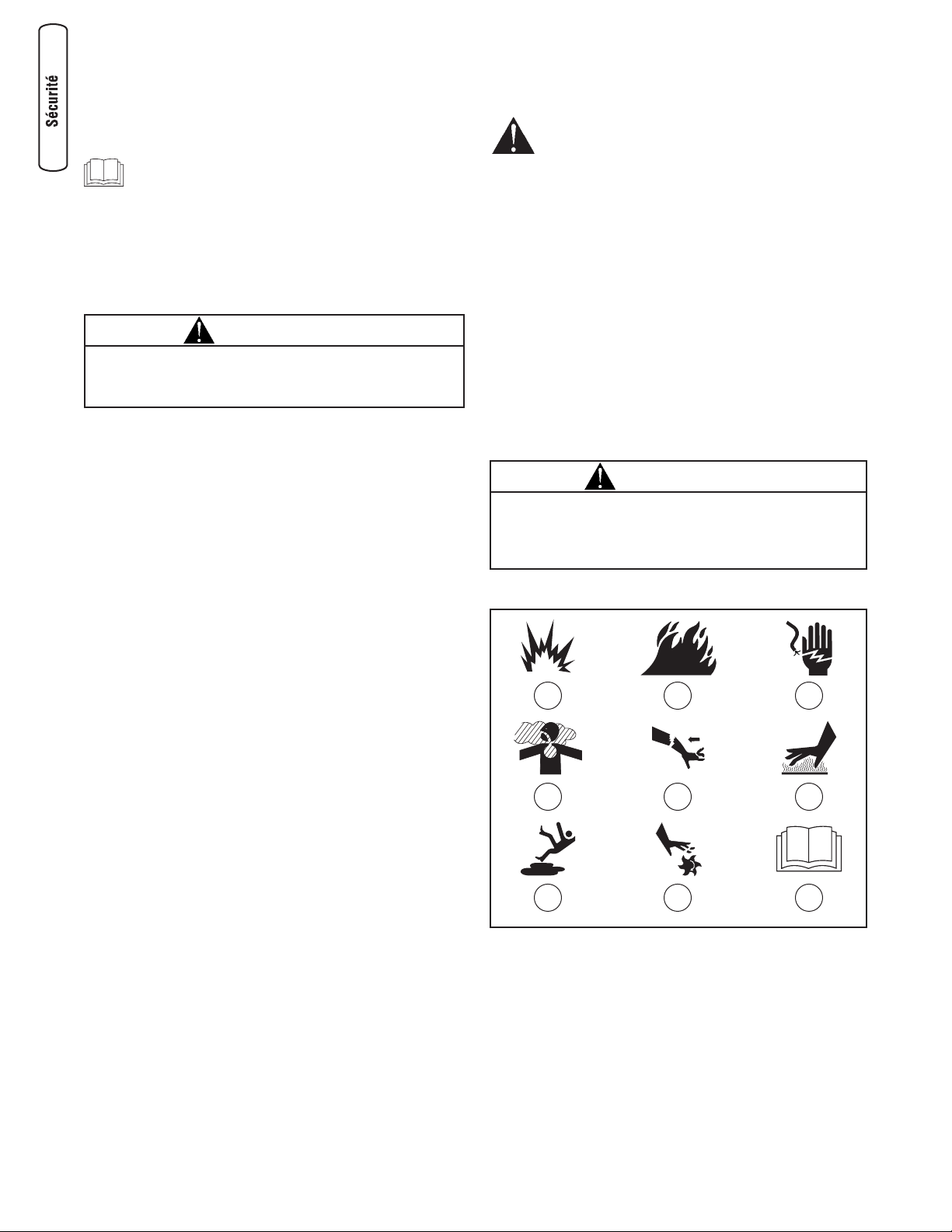
4 BRIGGSandSTRATTON.COM
Sécurité de l’opérateur
Description de l équipement
Lisez bien ce manuel et familiarisez-vous avec
votre pompe de transfert d’eau. Sachez à quoi elle
peut servir, ses limites et les dangers qui y sont
associés.
Cette pompe de transfert d’eau peut être utilisée pour
transférer de l’eau d’un emplacement inondé ou non voulu,
tel que le sous-sol. Elle peut aussi servir pour la vidange des
piscines ou pour l’irrigation.
Tout a été fait pour s'assurer que les renseignements
contenus dans ce manuel soient exacts et à jour. Toutefois,
nous nous réservons le droit de changer, de modifier ou
d'améliorer le produit et ce document en tout temps, et ce,
sans préavis.
Le dispositif antipollution de cette pompe de transfert d’eau
répond aux normes de la Environmental Protection Agency et
le California Air Resources Board.
Règles de sécurité
Ceci est la sûreté le symbole vif. Il est utilisé pour
vous alerter aux dangers de blessure personnels
potentiels. Obéir tous messages de sûreté qui
suivent ce symbole éviter la blessure ou la mort
possibles.
Le symbole indiquant un message de sécurité est
accompagné d'un mot indicateur (DANGER, ATTENTION,
AVERTISSEMENT), d'un message illustré et/ou d'un message
de sécurité visant à vous avertir des dangers. DANGER
indique un danger qui, s'il n'est pas évité, provoquera des
blessures graves, voire fatales. AVERTISSEMENT indique un
danger qui, s'il n'est pas évité, peut provoquer des blessures
graves, voire fatales. MISE EN GARDE indique un danger qui,
s'il n'est pas évité, peut provoquer des blessures mineures ou
légères. Le mot AVIS indique une situation pouvant
endommager l'équipement. Suivez les messages de sécurité
pour éviter ou réduire les risques de blessures ou de mort.
Symboles de danger et moyens
A - Explosion F - Surface chaude
B - Feu G - Surface glissante
C - Choc électrique H - Parties en mouvement
D - Emanations toxiques J - Manuel d'utilisation
E - Effet de recul
MISE EN GARDE
Cette pompe de transfert d’eau sont conçues pour pomper
SEULEMENT de l'eau claire qui n'est pas destinée à la
consommation par des humains.
AVERTISSEMENT
L’échappement du moteur de ce produit contient des produits
chimiques que l’État de Californie considère comme causant le
cancer, des déformations à la naissance ou d’autres dangers
concernant la reproduction.
A B C
D E
G H
F
J
Page 53

5
Français
AVERTISSEMENT
Un moteur en marche dégage du monoxyde de
carbone, un gaz inodore, incolore et toxique.
L’inhalation du monoxyde de carbone peut
causer des maux de tête, de la fatigue, des
étourdissements, le vomissement, de la
confusion, des crises épileptiques, des nausées,
l’évanouissement ou la mort.
• Faites fonctionner la pompe de transfert d’eau SEULEMENT à
l'extérieur.
• Évitez que les gaz d'échappement entrent dans un espace
restreint, par une fenêtre, une porte, une prise d'aération ou
toute autre ouverture.
• NE démarrez, ni ne faites fonctionner un moteur à l'intérieur ou
dans un espace fermé, même si les fenêtres ou les portes sont
ouvertes.
AVERTISSEMENT
Unintentional peut résulter dans feu ou
électrique.
LORSQUE VOUS RÉGLEZ OU RÉPAREZ VOTRE POMPE À EAU
• Débranchez toujours le câble de bougie et placez-le de façon à
ce qu'il ne soit pas en contact avec la bougie.
LORS DE TESTS D'ALLUMAGE DU MOTEUR
• Utilisez un vérificateur de bougies d'allumage approuvé.
• NE vérifiez PAS l'allumage lorsque la bougie d'allumage est enlevée.
AVERTISSEMENT
L'essence et ses vapeurs sont extrêmement
inflammables et explosives.
Le feu ou l'explosion risque de provoquer des
blessures graves, pouvant être fatales.
LORS DE L'AJOUT OU DE LA VIDANGE DU CARBURANT
• Éteignez la pompe de transfert d’eau et laissez-le refroidir au
moins 2 minutes avant de retirer le capuchon du réservoir de
carburant. Desserrez lentement le capuchon pour laisser la
pression s'échapper du réservoir.
• Remplissez ou vidangez le réservoir d'essence à l'extérieur.
• NE REMPLISSEZ PAS trop le réservoir. Laissez l'expansion de
l'essence.
• Si du carburant est renversé, attendez qu'il s'évapore avant de
démarrer le moteur.
• Éloignez l'essence des étincelles, des flammes, des veilleuses,
de la chaleur et de toute autre source d'inflammation.
• N'ALLUMEZ PAS de cigarette ou ne fumez pas à proximité de
l'appareil.
LORS DU DÉMARRAGE DE L'ÉQUIPEMENT
• Assurez-vous que la bougie d'allumage, le silencieux, le
bouchon à essence et le filtre à air sont en place.
• NE démarrez PAS le moteur lorsque la bougie d'allumage est
enlevée.
LORSQUE L'ÉQUIPEMENT FONCTIONNE
• NE pompez PAS des liquides inflammables comme de l'essence
ou du mazout.
• Cette pompe de transfert d’eau n'est pas conçue pour être
utilisée dans de l'équipement mobile ou les applications
marines.
• NE penchez PAS le moteur ou l'équipement à un angle où
l'essence peut se déverser.
• Fixez la pompe de transfert d’eau. Les charges contenues dans
les boyaux peuvent entraîner un renversement.
• N'arrêtez PAS le moteur en plaçant le levier d'étrangleur à la
position "Choke".
LORSQUE VOUS TRANSPORTEZ OU RÉPAREZ L'ÉQUIPEMENT
• Le réservoir d'essence doit être VIDE ou le robinet d'arrêt de
carburant doit être à la position fermée (OFF) pendant le
transport ou la réparation.
• Débranchez le câble de bougie.
LORSQUE VOUS ENTREPOSEZ L'ESSENCE OU UN ÉQUIPEMENT
AVEC UN RÉSERVOIR À ESSENCE
• Entreposez-le loin des appareils de chauffage, des fours, des
chauffe-eau, des sécheuses ou de tout autre appareil
électroménager disposant d'une veilleuse ou de toute autre
source d'inflammation risquant d'enflammer les vapeurs
d'essence.
AVERTISSEMENT
Usage de la pompe de transfert d’eau peut créer
puddles et glissant.
• Utilisez la pompe de transfert d’eau à partir d’une surface stable.
• La surface doit être inclinée et équipée d'écoulements afin de
réduire la possibilité de chutes dues aux surfaces glissantes.
AVERTISSEMENT
Démarreur et autre tourneres peut empêtrer
mains, cheveux, vêtement, ou accessoires.
• Ne placez JAMAIS vos mains ou des parties de votre corps à
l'intérieur de la pompe ou des boyaux lorsqu'elle fonctionne.
• N’utilisez JAMAIS la pompe de transfert d’eau sans bâti ou
couvercles protecteurs.
• NE portez PAS de vêtements lâches, de bijoux ou tout ce qui
risquerait d'être pris dans le démarreur ou toute autre pièce
rotative.
• Embouteiller des cheveux longs et enlève la bijouterie.
Page 54
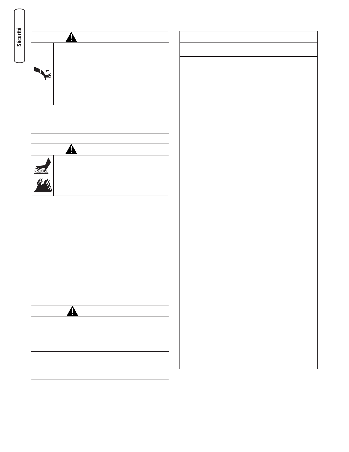
6 BRIGGSandSTRATTON.COM
AVERTISSEMENT
Un effet de recul (rétroaction rapide) de la corde
du démarreur pourrait entraîner des blessures
corporelles. L’effet de recul tirera votre main et
votre bras vers le moteur plus rapidement que
vous ne pouvez relâcher la corde.
Vous risquez ainsi de subir des fractures, des
ecchymoses ou des entorses.
Tenir les mains et le corps éloignés du dispositif
d'échappement de la pompe.
• Lors du démarrage du moteur, tirez lentement sur la corde
jusqu’à ce que vous sentiez une résistance et tirez alors
rapidement afin d’éviter un effet de recul.
• Fixez le tuyau d'échappement pour éviter un coup de fouet.
AVERTISSEMENT
Tout contact avec la zone du silencieux peut
causer des brûlures graves.
La chaleur et les gaz d’échappement peuvent
enflammer des matériaux combustibles et les
structures ainsi que causer des dommages au
réservoir d’essence et entraîner un incendie.
• NE touchez PAS aux pièces chaudes et évitez le contact avec les
gaz d’échappement.
• Laissez l'équipement refroidir avant de le toucher.
• Laissez un dégagement d’au moins 1,5 m (5 pi) tout autour de
la pompe de transfert d’eau, y compris au-dessus.
• Le Code of Federal Regulation (CFR) Title 36 Parks, Forests, and
Public Property exige que de l’équipement alimenté par un
moteur à combustion interne soit doté d’un pare-étincelles et
constamment maintenu en bon état fonctionnement,
conformément à la norme de service 5100-1C de la USDA
Forest ou à une révision de celle-ci. Dans l’État de la Californie,
un pare-étincelles est requis en vertu de la section 4442 du
California Public Resources Code. Il se peut que d’autres États
aient des lois semblables.aux terres fédérales. Si vous équipez le
silencieux d'un pare-étincelles, il doit être en bon état de
fonctionnement.
AVIS
Le traitement inadéquat de la pompe de transfert d’eau
peut l'endommager et réduire sa durée de vie utile.
• Si vous avez des questions à propos de l’utilisation prévue de
cet appareil, consultez votre détaillant ou communiquez avec un
centre de service qualifié.
• Assurez-vous que la chambre de la pompe est pleine d'eau
avant de lancer le moteur. Ne faites JAMAIS fonctionner la
pompe sans l'amorcer.
• Utilisez un boyau semi-rigide du côté aspiration de la pompe.
• Utilisez la pompe de transfert d’eau seulement pour les
utilisations pour lesquelles elle est conçue.
• Ne pompez que de l'eau qui n'est pas destinée à la
consommation des humains.
• Pomper de l'eau de mer, des breuvages, des acides, des
solutions chimiques ou tout autre liquide qui favorise la
corrosion peut endommager la pompe.
• Assurez-vous que toutes les connexions sont étanches à l'air.
• N'obstruez PAS le boyau d'entrée ou d'évacuation, d'aucune
manière.
• Ne faites JAMAIS fonctionner la pompe sans panier-filtre à
l'extrémité du boyau d'aspiration.
• NE dépassez PAS la hauteur d’aspiration maximale de 8 m
(25 pi) et une hauteur totale de 69 m (225 pi). Utilisez la hauteur
d’aspiration la plus courte possible.
• Ne laissez JAMAIS de véhicules passer sur les boyaux. Si un
boyau doit traverser une route, utilisez des planches de chaque
côté du boyau pour permettre aux véhicules de passer sans
l'obstruer ou l'écraser.
• Ancrez la pompe pour l'empêcher de bouger ou empêcher le
déplacement de l'équipement, en particulier si elle est située
près d'un fossé ou d'un ravin ouvert. L'équipement pourrait
tomber dans le fossé ou le ravin.
• Placez l'équipement loin du bord d'une rivière ou d'un lac dont
la berge pourrait s'effondrer.
• N'insérez AUCUN objet dans les fentes de refroidissement.
• N'utilisez JAMAIS un appareil ayant des pièces brisées ou
manquantes ou sans bâti ou couvercles protecteurs.
• NE neutralisez AUCUN dispositif de sécurité de cette machine.
• N'utilisez JAMAIS le tuyau à haute pression comme poignée
pour déplacer l'appareil. Utilisez toujours la poignée de
l'appareil.
• Vérifiez la présence de fuites ou les signes de détérioration du
système de combustible, comme un tuyau usé ou spongieux,
des brides de serrage desserrées ou manquantes, ou un
réservoir ou un bouchon endommagé. Réparez toutes les
défectuosités avant d'utiliser le nettoyeur à pression.
• Cet appareil est conçu pour être utilisé uniquement avec des
pièces Briggs & Stratton approuvées. Si l'appareil est utilisé
avec des pièces qui NE sont PAS conformes aux
caractéristiques minimales, tous les risques et responsabilités
incomberont à l'utilisateur.
MISE EN GARDE
Des vitesses de fonctionnement excessivement élevées
peuvent causer des blessures ou endommager la pompe
de transfert d’eau.
Des vitesses excessivement lentes produisent une charge
importante.
• NE modifiez PAS la vitesse régulée du moteur.
• NE modifiez PAS la pompe de transfert d’eau, d'aucune façon.
• NE laissez PAS les personnes non qualifiées ou les enfants
opérer ou entretenir la pompe de transfert d’eau.
Page 55
7
Français
Assemblage
Lisez le manuel de l’opérateur en entier avant de
tenter d’assembler ou d’utiliser votre nouveau
nettoyeur à haute pression.
Votre pompe de transfert d’eau doit être assemblée et vous
pourrez l’utiliser après l’avoir correctement remplie d’huile et
d’essence recommandées.
Si vous avez n'importe quels problèmes avec l'assemblée
de votre pompe de transfert d’eau, s'il vous plaît appeler le
helpline de pompe de transfert d’eau à (800) 743-4115.
Si vous téléphonez pour obtenir de l'aide, veuillez avoir
disponibles les renseignements du données étiquettent:
numéro de modèle, de révision et de série. Consultez la
section Commandes et fonctions de la pompe de transfert
d’eau pour connaître l’emplacement de l’étiquette de données.
Déballage du pompe de transfert d’eau
1. Saque todo el contenido de la caja de cartón, a
excepción de la pompe de transfert d’eau.
2. Ouvrez la boîte d’expédition en coupant tous les coins
du haut vers le bas.
3. Vérifiez que tous les articles fournis sont présents avant
de commencer le montage.
Les articles dans la boîte incluent:
• Pompe de transfert d’eau
• Bouteille d'huile
• Sac de pièces (comprenant ce qui suit):
• Ce manuel d'utilisation
• Carte d'enregistrement du propriétaire
• Panier-filtre et barbelure
• Barbelure de boyau (2)
• Manchon de barbelure (2)
• Joint d'étanchéité en caoutchouc (2)
• Bride de serrage (3)
• Ensemble anti-vibrations
• Tampon anti-vibrations (4)
• Boulon (4)
• Rondelle (4)
• Contre-écrou (4)
• Feuillet d'instructions
Pour mettre la pompe de transfert d’eau en état de
fonctionnement, les tâches suivantes doivent être
effectuées:
1. Remplir et envoyer la carte d'enregistrement.
2. Fixation des tampons anti-vibrations.
3. Ajoutez de l'huile au carter du moteur.
4. Ajoutez de l'essence dans le réservoir.
5. Fixation du boyau d'aspiration.
6. Fixation du boyau d'évacuation (facultatif).
7. Déplacement de la pompe vers un emplacement
sécuritaire.
8. Amorçage de la pompe de transfert d’eau.
9. Localisation du panier-filtre dans la source d'eau.
Fixation des tampons anti-vibrations
Pour installer les tampons anti-vibrations, vous aurez besoin
des outils suivants:
`• Clé de 10 mm
• Clé à douilles avec douille de 10 mm
Fixez les tampons anti-vibrations sur la pompe de transfert
d’eau de la façon illustrée sur le feuillet d'instructions inclus
avec l'ensemble anti-vibrations.
IMPORTANT: Vous devez fixer les tampons anti-vibrations
avant d'ajouter de l'huile ou de l'essence.
Ajoutez de l'huile à moteur
1. Placez le pompe de transfert d’eau sur une surface
plane.
2. Nettoyez la surface autour de l’orifice de remplissage
d’huile et enlevez la jauge d’huile.
REMARQUE: Consultez la section Huile au sujet des
recommandations relatives à l’huile. Vérifiez si la viscosité de
la bouteille d’huile fournie est appropriée à la température
ambiante.
3. À l'aide d'un entonnoir pour huile (optionnel), versez
lentement le contenu complet de la bouteille d'huile
fournie dans l'orifice de remplissage.
4. Replacez la jauge d’huile et serrez-la solidement.
Ajoutez de l'essence
L’essence satisfait les exigences suivantes:
• Essence sans plomb fraîche et propre.
• Un indice d’octane minimum de 87/87 AKI (91 IOR).
Utilisation à des altitudes élevées, consultez la section
Altitude élevée.
• Une essence avec jusqu’à 10 % d’éthanol (gazohol) ou
jusqu’à 15 % d’éther méthyltertiobutylique est acceptable.
AVIS
Un traitement inapproprié du pompe de transfert d’eau risque
de l'endommager et de raccourcir sa durée d'utilisation.
• NE tentez JAMAIS de démarrer le moteur sans d’abord vérifier
s'il a été entretenu de façon appropriée avec l’huile
recommandée. Cela risquerait d'entraîner un bris de moteur.
Page 56
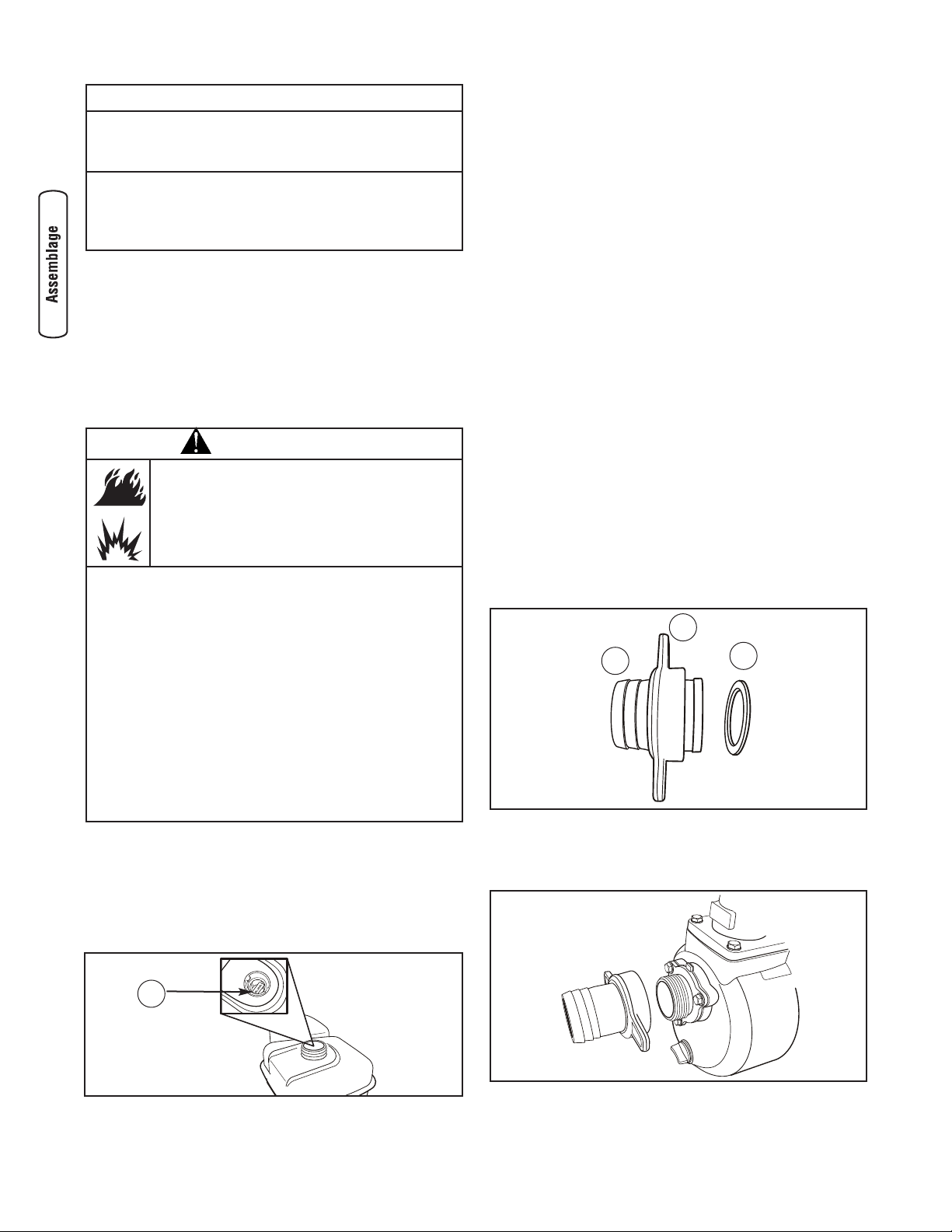
8 BRIGGSandSTRATTON.COM
Au moment d’ajouter de l’essence, la mélanger avec un
stabilisateur d’essence afin de protéger le circuit d’alimentation
contre la formation de dépôts de gomme. Voir Entreposage.
Les essences ne sont pas toutes pareilles. Si vous éprouvez
des problèmes de démarrage ou de performance après avoir
utilisé une essence, changez de fournisseur d’essence ou de
marque d’essence. Le fonctionnement du moteur avec de
l’essence est certifié. Ce dispositif antipollution pour ce moteur
est de type EM (Modifications de moteur).
1. Nettoyez la partie autour du bouchon du réservoir
d'essence, enlevez le bouchon.
2. Ajoutez lentement de l'essence sans plomb ordinaire dans
le réservoir d'essence. Remplissez jusqu'à la marque de
niveau de carburant (A). Faites attention pour ne pas trop
remplir.
3. Remettez le bouchon à essence et attendre le carburant
renversé pour s'évaporer.
Altitude élevée
À des altitudes de plus de 5 000 pi (1 524 m), il convient
d’utiliser des essences présentant un indice d’octane minimal
de 85/85 AKI (89 IOR). Un réglage pour les altitudes élevées
est requis pour respecter les normes relatives aux émissions.
Une utilisation sans ce réglage entraîne une diminution de la
performance ainsi qu’une augmentation de la consommation
d’essence et des émissions. Consultez un détaillant autorisé
Briggs & Stratton pour des renseignements sur les réglages
pour les altitudes élevées. L’utilisation à des altitudes
inférieures à 762 mètres (2 500 pieds) avec la trousse pour
les altitudes élevées est déconseillée.
Fixation du boyau d'aspiration
Vous aurez besoin des outils suivants pour fixer le boyau
d’aspiration au panier-filtre:
• Tournevis standard de 1/4" ou 6 mm
Branchement du boyau d'aspiration à la pompe
Utilisez un boyau disponible sur le marché. Le boyau
d'aspiration doit être renforcé et possédé une paroi semirigide ou faite de matériau tressé. N'utilisez PAS un boyau
dont le diamètre interne est plus petit que la taille de l'orifice
d'aspiration de la pompe.
1. Glissez le manchon de barbelure (B) sur la barbelure
(C). Insérez un joint d'étanchéité en caoutchouc (D) à
l'extrémité du manchon de barbelure.
2. Vissez le manchon de boyau sur la pompe en sens
horaire jusqu'à ce que la barbelure soit fixée
solidement.
AVIS
Évitez d’endommager le pompe de transfert d’eau.
Le manquement à suivre les recommandations relatives à
l’huile du manuel d’utilisation annule la garantie.
• NE PAS utiliser d’essence non approuvée telle que E85.
• NE PAS mélanger l’huile avec l’essence.
• NE PAS modifier le moteur afin qu’il fonctionne avec d’autres
types d’essence.
AVERTISSEMENT
L'essence et ses vapeurs sont extrêmement
inflammables et explosives.
Le feu ou l'explosion risque de provoquer des
blessures graves, pouvant être fatales.
LORS DE L'AJOUT DU CARBURANT
• Éteignez le pompe de transfert d’eau et laissez-le refroidir au
moins 2 minutes avant de retirer le capuchon du réservoir de
carburant. Desserrez lentement le capuchon pour laisser la
pression s'échapper du réservoir.
• Remplissez ou vidangez le réservoir d'essence à l'extérieur.
• NE remplissez PAS trop le réservoir. Laissez l'expansion de
l'essence.
• Attend le carburant renversé pour s'évaporer avant de démarrer
le moteur.
• Éloignez l'essence des étincelles, des flammes, des veilleuses,
de la chaleur et de toute autre source d'inflammation.
• N'ALLUMEZ PAS de cigarette ou ne fumez pas à proximité de
l'appareil.
D
B
C
A
Page 57

9
Français
3. Glissez la bride de serrage (A) sur l'extrémité du boyau
(B). Glissez le boyau d'aspiration sur la barbelure (C).
Serrez la bride de serrage à l'aide d'un tournevis
régulier de 1/4 po (6 mm).
Fixation du boyau d'aspiration au panier-filtre
Glissez la bride de serrage sur le boyau. Fixez l'extrémité
ouverte du boyau d'aspiration à la barbelure du panier-filtre.
Serrez la bride de serrage à l'aide d'un tournevis régulier de
1/4 po (6 mm).
Branchement du boyau d'évacuation (facultatif)
Si désiré, utilisez un boyau disponible sur le marché.
N'utilisez PAS un boyau dont le diamètre interne est plus
petit que la taille de l'orifice d'évacuation de la pompe.
1. Glissez le manchon de barbelure sur la barbelure.
Insérez un joint d'étanchéité en caoutchouc à
l’extrémité du manchon de barbelure tel que montré
plus haut.
2. Vissez le manchon de boyau sur la pompe en sens
horaire jusqu'à ce que la barbelure soit fixée
solidement.
3. Glissez la bride de serrage sur l'extrémité du boyau
d'évacuation. Glissez le boyau d'évacuation sur la
barbelure. Serrez la bride de serrage à l'aide d'un
tournevis régulier de 1/4 po (6 mm).
C
A
B
Page 58
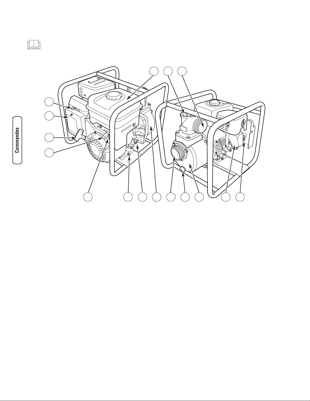
10 BRIGGSandSTRATTON.COM
A - Réservoir d'essence — Remplissez le réservoir avec de
l'essence ordinaire sans plomb. Laissez toujours de la
place pour l'expansion de l'essence.
B - Amorceur — Remplissez la pompe d'eau ici pour
amorcer la pompe avant de la faire démarrer.
C - Orifice d'évacuation — Branchez le boyau d'évacuation
à cet endroit.
D - Levier d'étrangleur — Utilisé lors du démarrage à froid
d'un moteur.
E - Filtre à air — Protège le moteur en filtrant la poussière
et les débris dans la prise d'air.
F - Lanceur — Utilisé pour le démarrage du moteur.
G - Levier de papillon — Utilisé pour régler la vitesse du
moteur afin de contrôler le débit de la pompe.
H - Interrupteur ON/OFF — Réglez cet interrupteur sur "On"
avant d'utiliser le lanceur. Réglez l'interrupteur sur "Off"
pour arrêter le moteur.
J - Bouchon de vidange d’huile — Vidangez l’huile du
moteur ici.
K - Bouchon de remplissage — Vérifiez le niveau d'huile et
videz l'huile à moteur ici.
L - Étiquette de données — Indique le numéro de modèle,
de révision et de série de la pompe de transfert d’eau.
Veuillez avoir ces renseignements sous la main lors
d'appel de service.
M - Prise d'aspiration — Branchez le boyau d'aspiration
renforcé ici.
N - Bouchon de vidange d'eau — Retirez-le pour vidanger
l'eau de la pompe et rincez les composants internes avec
de l'eau claire.
P - Chambre de la pompe — Assurez-vous qu'elle est pleine
d'eau avant de lancer le moteur.
R - Information de moteur — Affranchi sur la couverture de
soupape. Indique le numéro de modèle, de type et code
de la moteur. Veuillez avoir ces renseignements sous la
main lors d'appel de service.
S - Robinet d'arrêt de carburant — Utilisé pour alimenter le
moteur en essence ou pour couper l'alimentation en
essence du moteur.
Article non montrés:
Panier-filtre — Utilisé pour limiter le passage de matériels
abrasifs dans la pompe.
Fonctions et commandes
Lisez ce manuel d'utilisation ainsi que les règles de sécurité avant de faire fonctionner votre pompe de transfert d’eau.
Comparez les illustrations avec votre nettoyeur à pression pour vous familiariser avec l'emplacement des différents
boutons et réglages. Conservez ce manuel pour référence ultérieure.
G
E
J
F
K
D
H L M N P S
CBA
R
Page 59

11
Français
Opération
Si vous éprouvez des problèmes lors de l’utilisation de votre
pompe de transfert d’eau, veuillez appeler la ligne d’aide du
pompe de transfert d’eau au (800) 743-4115.
Pour un fonctionnement sécuritaire
Dégagements et mouvement de l'air
Placez la pompe de transfert d’eau dans un endroit bien ventilé
qui permet l'élimination des gaz d'échappement mortels.
N'installez PAS la pompe de transfert d’eau dans un endroit où
les gaz d'échappement (A) pourraient s'accumuler et pénétrer
ou être aspirés dans un édifice qui pourrait être occupé.
Assurez-vous que les gaz d'échappement ne puissent entrer
par une fenêtre, une porte, une prise d'aération ou une autre
ouverture qui pourrait leur permettre de s'accumuler dans un
espace restreint. Tenez aussi compte des vents dominants et
des courants d'air au moment de choisir l'endroit où vous
installerez la pompe de transfert d’eau.
Qu'est-ce que la "hauteur"?
La hauteur fait référence à la hauteur d’une colonne d’eau qui
peut être évacuée de la pompe.
La hauteur de succion est la distance verticale entre le centre
de la pompe et la surface du liquide sur le côté de succion
de la pompe. Peut être aussi référé à comme “l'ascenseur de
succion”. La pression atmosphérique de 14,7 livres par
pouce carré à l'ascenseur de tête de succion de limites de
niveau de la mer à moins qu'approximativement 26 pieds
pour n'importe quelle pompe.
La hauteur de décharge est la distance verticale entre le port
de décharge de la pompe et le point de décharge, qui est la
surface liquide si le tuyau est submergé ou pompant dans le
fond d'un réservoir.
La hauteur totale est la somme de la valeur de tête de
succion plus la valeur de tête de décharge.
À mesure que la hauteur de pompage de l'eau augmente, le
débit de pompage diminue. La longueur, le type et la taille
des boyaux d'aspiration et d'évacuation peuvent aussi
modifier grandement le débit de pompage.
Est donc important que le fonctionnement de l'aspiration
représente la partie la plus courte du pompage total. Cela
réduira la durée d’amorçage et améliorera la performance de
la pompe en augmentant la hauteur d’évacuation.
La hauteur d’aspiration devrait être d’un maximum de 8 m
(25 pi) et la hauteur d’évacuation d’un maximum de 25 m
(81 pi). La hauteur totale ne peut dépasser 32 m (106 pi) (à
la page suivante).
Déplacement de la pompe vers un emplacement
sécuritaire
Pour une meilleure performance de la pompe, placez-la sur
une surface plane le plus près possible de l'eau à pomper.
Fixez la pompe de transfert d’eau afin d’éviter un
renversement. Utilisez des boyaux qui ne sont pas plus longs
que nécessaire.
IMPORTANT: Dirigez l'extrémité ouverte du boyau
d'évacuation loin de la maison, d'appareils électriques et de
tout objet ne devant pas être mouillé.
AVERTISSEMENT
La chaleur et les gaz d’échappement peuvent
enflammer des matériaux combustibles et les
structures ainsi que causer des dommages au
réservoir d’essence et entraîner un incendie.
• Laissez un dégagement d’au moins 1,5 m (5 pi) tout autour de
la pompe de transfert d’eau, y compris au-dessus.
AVERTISSEMENT
Un moteur en marche dégage du monoxyde de
carbone, un gaz inodore, incolore et toxique.
L’inhalation du monoxyde de carbone peut
causer des maux de tête, de la fatigue, des
étourdissements, le vomissement, de la
confusion, des crises épileptiques, des nausées,
l’évanouissement ou la mort.
• Faites fonctionner le pompe de transfert d’eau SEULEMENT à
l'extérieur.
• Évitez que les gaz d'échappement entrent dans un espace
restreint, par une fenêtre, une porte, une prise d'aération ou
toute autre ouverture.
• NE démarrez, ni ne faites fonctionner un moteur à l'intérieur ou
dans un espace fermé, même si les fenêtres ou les portes sont
ouvertes.
AVERTISSEMENT
L'essence et ses vapeurs sont extrêmement
inflammables et explosives.
Le feu ou l'explosion risque de provoquer des
blessures graves, pouvant être fatales.
LORSQUE L'ÉQUIPEMENT FONCTIONNE
• Cette pompe de transfert d’eau n'est pas conçue pour être
utilisée dans de l'équipement mobile ou les applications marines.
• NE penchez PAS le moteur ou l'équipement à un angle où
l'essence peut se déverser.
• Fixez la pompe de transfert d’eau. Les charges contenues dans
les boyaux peuvent entraîner un renversement.
A
Page 60

12 BRIGGSandSTRATTON.COM
Amorçage de la pompe de transfert d’eau
1. Enlevez le bouchon fixé sur le dessus de la pompe.
2. Remplissez la pompe avec de l'eau claire jusqu'à la
partie supérieure de l'orifice d'évacuation.
3. Replacez le bouchon de la pompe.
Localisation du panier-filtre dans la source d'eau
Placez le panier-filtre dans l'eau à pomper. Le panier doit
être complètement immergé.
Pompe de transfert d’eau type illustrée
Hauteur d'évacuation
- 25 m (81 pieds)
maximum
Hauteur d'aspiration
- 8 m (25 pieds)
maximum
Hauteur totale
- 32 m (106 pieds)
maximum
AVIS
Un traitement inapproprié du pompe de transfert d’eau
risque de l'endommager et de raccourcir sa durée
d'utilisation.
• Assurez-vous que la chambre de la pompe est pleine d'eau
avant de lancer le moteur. Ne faites JAMAIS fonctionner la
pompe sans l'amorcer.
AVIS
Un traitement inapproprié du pompe de transfert
d’eau risque de l'endommager et de raccourcir sa
durée d'utilisation.
• Ne faites JAMAIS fonctionner la pompe sans panier-filtre à
l'extrémité du boyau d'aspiration
• Ne placez pas le panier-filtre dans le sable ou la vase, dans un
seau ou sur des pierres.
• NE faites PAS fonctionner la pompe de transfert d’eau lorsqu'il
n'y plus d'eau car cela risquerait d'endommager les joints
d'étanchéité.
Page 61

13
Français
Démarrage de la pompe de transfert d’eau
Suivez les directives de démarrage suivantes:
1. Assurez-vous que l'unité est sur une surface plane et
que la chambre de la pompe est amorcée.
2. Tournez la vanne de combustible blanche (A) à la
position "On". La poignée de la vanne de combustible
sera à la verticale (pointant vers le sol).
3. Poussez l'interrupteur ON/OFF (B) sur "On".
4. Placez le levier du régime du moteur (C) à la position
"Fast" ( ).
5. Placez le levier d'étrangleur (D) à la position “Choke”
().
6. Prenez la poignée du lanceur et tirez-la jusqu'à ce que
vous sentiez une légère résistance. Tirez alors
rapidement sur la poignée pour dépasser la résistance
de la compression, empêcher les effets de recul et
démarrer le moteur.
IMPORTANT: Si le moteur se noie, placez le levier
d'étrangleur en position "Run" ( ) et tirez plusieurs fois sur
la poignée jusqu'à ce que le moteur démarre.
7. Déplacez le levier d'étrangleur en position "Run" ( )
un peu à la fois durant quelques secondes quand il fait
chaud ou durant quelques minutes quand il fait froid.
Laissez le moteur tourner en douceur avant chaque
changement. Faites fonctionner la pompe avec
l'étrangleur en position "Run" ( ).
IMPORTANT: Il faudra peut-être quelques minutes avant que
la pompe de transfert d’eau ne commence à pomper de l'eau.
Le débit de la pompe est contrôlé en réglant le régime du
moteur. Déplacer le levier du régime du moteur vers la
position "Fast" ( ) augmentera le débit de la pompe et le
déplacer vers la position "Slow" ( ) diminuera le débit de la
pompe.
AVERTISSEMENT
Un effet de recul (rétroaction rapide) de la corde
du démarreur pourrait entraîner des blessures
corporelles. L’effet de recul tirera votre main et
votre bras vers le moteur plus rapidement que
vous ne pouvez relâcher la corde.
Vous risquez ainsi de subir des fractures, des
ecchymoses ou des entorses.
• Lors du démarrage du moteur, tirez lentement sur la corde
jusqu’à ce que vous sentiez une résistance et tirez alors
rapidement afin d’éviter un effet de recul.
AVERTISSEMENT
Tout contact avec la zone du silencieux peut
causer des brûlures graves.
La chaleur et les gaz d’échappement peuvent
enflammer des matériaux combustibles et les
structures ainsi que causer des dommages au
réservoir d’essence et entraîner un incendie.
• NE touchez PAS aux pièces chaudes et évitez le contact avec les
gaz d’échappement.
• Laissez l'équipement refroidir avant de le toucher.
• Laissez un dégagement d’au moins 1,5 m (5 pi) tout autour de
la pompe de transfert d’eau, y compris au-dessus.
• Le Code of Federal Regulation (CFR) Title 36 Parks, Forests, and
Public Property exige que de l’équipement alimenté par un
moteur à combustion interne soit doté d’un pare-étincelles et
constamment maintenu en bon état fonctionnement,
conformément à la norme de service 5100-1C de la USDA
Forest ou à une révision de celle-ci. Dans l’État de la Californie,
un pare-étincelles est requis en vertu de la section 4442 du
California Public Resources Code. Il se peut que d’autres États
aient des lois semblables.aux terres fédérales. Si vous équipez le
silencieux d'un pare-étincelles, il doit être en bon état de
fonctionnement.
A
B
C
D
Page 62

14 BRIGGSandSTRATTON.COM
Arrêt de la pompe de transfert d’eau
1. Placez le levier du régime du moteur à la position
"Slow" ( ).
2. Poussez l'interrupteur ON/OFF sur la position "Off".
3. Tournez la vanne de combustible blanche à la position
“Off”.
Vidange et rinçage de la pompe de transfert
d’eau
1. Débranchez et vidangez les boyaux d'aspiration et
d'évacuation.
2. Enlevez le bouchon de vidange au bas de la pompe.
3. Retirez le bouchon sur le dessus de la pompe et rincez
les composants internes de la pompe avec de l'eau
claire.
4. Revissez les deux bouchons et torsion.
AVERTISSEMENT
Des explosions dans le silencieux, un incendie
ou des dommages au moteur peuvent survenir.
• N’ arrêtez PAS le moteur en plaçant le levier d’étrangleur à la
position “Choke”
().
Page 63

15
Français
Entretien
Calendrier d'entretien
Respectez le calendrier d'entretien du nettoyeur selon le nombre d'heures de fonctionnement ou le temps écoulé, le premier
des deux prévalant. Un entretien plus fréquent est requis lors d'une utilisation dans des conditions défavorables telles
qu'indiquées ci-dessous.
¹ Changez l'huile après les cinq (5) premières heures de fonctionnement et par la suite aux 50 heures de fonctionnement ou une fois l'an (selon
le premier de ces événements). Changez l'huile plus souvent si vous utilisez la pompe dans un milieu sale ou poussiéreux.
² Remplacez les pièces plus fréquemment si vous utilisez l'appareil dans un milieu sale ou poussiéreux.
TÂCHE D'ENTRETIEN
DATES D'ENTRETIEN
DATES D'ENTRETIEN
Avant chaque
utilisation
Aux 25 heures
ou 1 fois l'an
Aux 50 heures
ou 1 fois l'an
Aux 100 heures
ou 1 fois l'an
Nettoyer les débris
X
Vérifier le niveau d'huile
X
Changer l'huile du moteur
X¹
Faire l'entretien du filtre à air
X²
Faire l'entretien de la bougie
d'allumage
X
Faire l'entretien du pare-étincelles
X
Nettoyer le système de refroidissement
X²
Préparer pour l'entreposage Si le nettoyeur ne sera pas utilisé durant plus de 30 jours.
Recommandations générales
Un entretien régulier améliorera la performance et prolongera
la durée de vie de la pompe de transfert d’eau. Consultez un
détaillant autorisé Briggs & Stratton pour l'entretien.
La garantie de la pompe de transfert d’eau ne couvre pas les
éléments soumis à l'abus ou à la négligence de l'opérateur.
Pour qu'elle soit entièrement valide, l'opérateur doit
entretenir la pompe de transfert d’eau conformément aux
instructions contenues dans ce manuel.
Certains ajustements devront être faits périodiquement pour
assurer un entretien adéquat de la pompe de transfert d’eau.
Il faut effectuer toutes les opérations d'entretien et les
réglages au moins une fois par saison. Suivez les
instructions du Calendrier d'entretien ci-dessus.
REMARQUE: Une fois par année, vous devez nettoyer ou
remplacer la bougie d'allumage et remplacer le filtre à air.
Une nouvelle bougie d'allumage et un filtre à air propre
permettent d'assurer que le mélange essence-air est adéquat
en plus de contribuer au meilleur fonctionnement de votre
moteur et d'augmenter sa durée de vie.
Contrôle des émissions
L'entretien, le remplacement ou la réparation des
dispositifs et systèmes antipollution peuvent être effectués
par un établissement de réparation de moteurs hors route
ou par une personne qualifiée. Pour obtenir un entretien
« sans frais » du dispositif antipollution, le travail doit être
effectué par un détaillant autorisé par le fabricant. Voir la
garantie du dispositif antipollution.
Entretien du pompe de transfert d’eau
L'entretien consiste à garder la pompe de transfert d’eau
propre. Entreposez l'unité dans un environnement propre et
sec où elle ne sera pas exposée à une poussière, saleté,
humidité excessive ni à des vapeurs corrosives. Les fentes
de refroidissement du moteur de la pompe de transfert d’eau
ne doivent pas être obstruées par de la saleté, des feuilles ou
d'autres corps étrangers.
REMARQUE: N'utilisez PAS de boyau d'arrosage pour nettoyer
le moteur de la pompe de transfert d’eau. L'eau peut entrer
dans le système d'alimentation et causer des problèmes.
Nettoyage
À tous les jours ou avant de l'utiliser, regardez autour ou
sous la pompe s'il y a des signes de fuites d'huile ou
d'essence. Nettoyez les débris accumulés à l'intérieur et à
l'extérieur de la pompe de transfert d’eau. Gardez toujours la
tringlerie, le ressort et les autres commandes du moteur
propres. Gardez la zone autour et derrière le silencieux libre
de débris combustibles. Utilisez une faible pression d'air (25
psi au maximum) pour souffler les saletés. Inspectez les
fentes de refroidissement et les orifices de la pompe de
transfert d’eau. Ces ouvertures doivent demeurer propres et
non obstruées.
Les parties du moteur doivent être gardées propres afin de
réduire le risque de surchauffe et d'inflammation des débris
accumulés.
• Utilisez un linge humide pour nettoyer les surfaces
extérieures.
Page 64
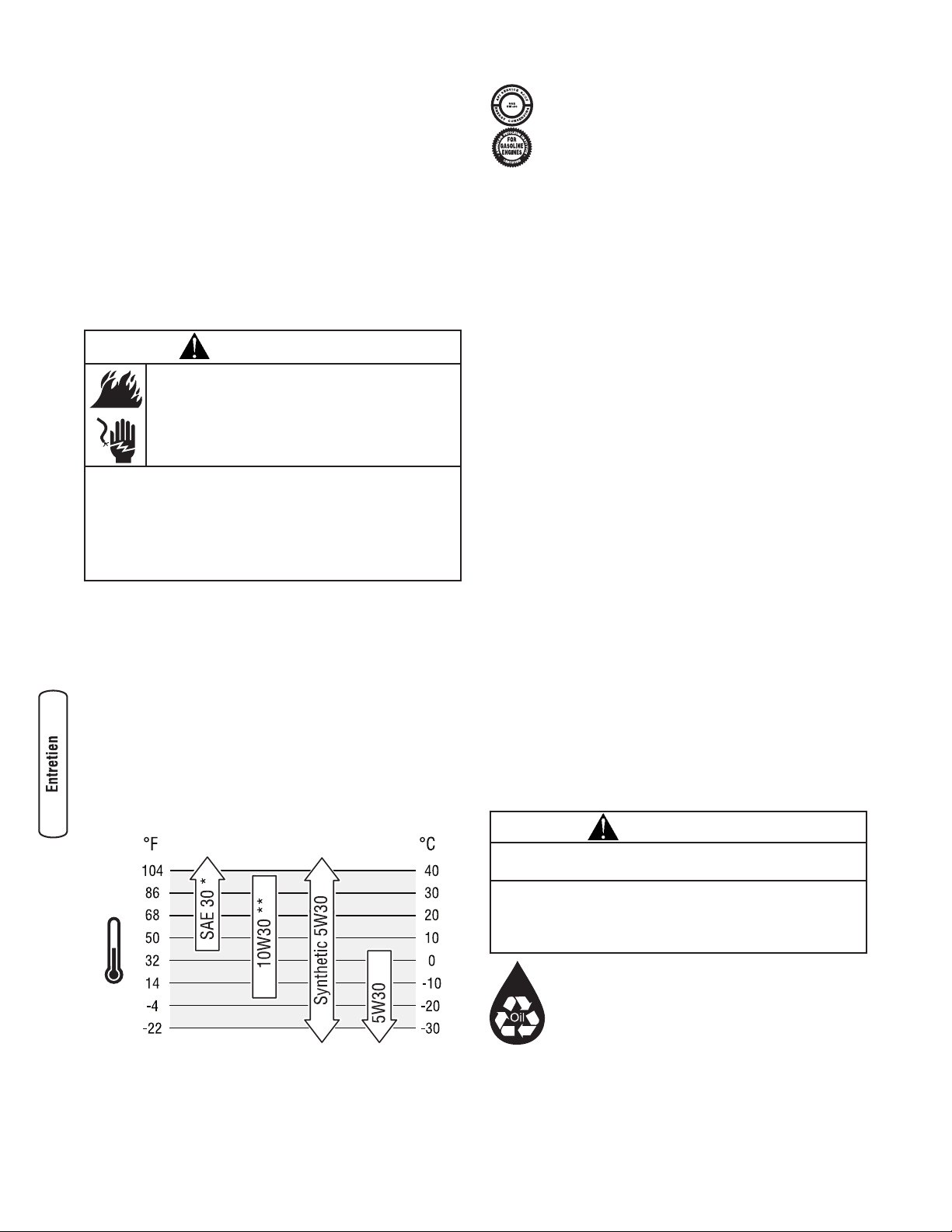
16 BRIGGSandSTRATTON.COM
• Utilisez une brosse à soies douces pour détacher les
accumulations de saletés ou d'huile.
• Utilisez un aspirateur pour ramasser les saletés et
débris.
Enlevez les dépôts de vase et de boue dans le corps de la
pompe :
• Dévissez le bouchon de l'amorceur et retirez le
bouchon de vidange.
• Rincez les composants internes de la pompe avec de
l'eau propre.
Entretien du moteur
Huile
Recommandations relatives à l’huile
Nous recommandons l’utilisation des huiles certifiées par
garantie Briggs & Stratton pour obtenir une meilleure
performance. Les autres huiles détergentes de haute qualité
sont acceptables si elles ont les cotes pour service SF, SG,
SH, SJ ou plus. N’utilisez pas d’additifs spéciaux.
Les températures extérieures déterminent la viscosité de
l’huile requise pour le moteur. Utilisez le tableau pour choisir
la meilleure viscosité pour la gamme de températures
extérieures attendues.
* Sous 40ºF (4ºC), l’utilisation d’une huile SAE 30 entraîne un
démarrage difficile.
** Au-dessus de 80ºF (27ºC), l’utilisation d’une huile 10W30 peut
entraîner une consommation d’huile plus élevée. Vérifiez
fréquemment le niveau d’huile.
REMARQUE : L’huile synthétique respectant la
marque d’homologation ILSAC GF-2, API et portant
le symbole d’entretien API (montré à la gauche) avec
la mention « SJ/CF (économie d’énergie) » ou plus,
est une huile acceptable pour toutes les
températures. L’utilisation d’huile synthétique ne
modifie pas les intervalles de changement d’huile.
Vérification du niveau d'huile
Il est nécessaire de vérifier le niveau d'huile avant chaque
utilisation ou après chaque période de 5 heures d'utilisation.
Gardez un niveau d'huile constant.
1. Assurez-vous que nettoyeur à pression se trouve sur
une surface de niveau.
2. Enlevez le bouchon de remplissage d’huile et essuyez
avec un linge.
3. Vérifiez que l’huile est sur le point de déborder par
l’orifice de remplissage.
4. Replacez-la et resserrez-la.
Ajout d’huile
1. Assurez-vous que nettoyeur à pression se trouve sur
une surface de niveau.
2. Vérifiez le niveau d’huile de la manière décrite dans la
rubrique Vérification du niveau d’huile.
3. Au besoin, videz lentement l’huile dans l’orifice de
remplissage d’huile, jusqu’à ce qu’elle déborde par
l’orifice du couvercle de remplissage d’huile.
4. Replacez-la et resserrez-la.
Vidange de l'huile moteur
Changez l'huile après la première période de 5 heures
d'utilisation. Par la suite, changez l'huile après chaque
période de 50 heures d'opération. Si vous utilisez votre
pompe de transfert d’eau dans des endroits très sales ou
poussiéreux ou dans des conditions de chaleur intense,
changez alors l'huile plus fréquemment.
CONSERVER HORS DE LA PORTÉE DES ENFANTS.
NE PAS POLLUER. PRÉSERVER LES
RESSOURCES. RETOURNER LA VIEILLE HUILE
DANS DES CENTRES DE RÉCUPÉRATION.
AVERTISSEMENT
Unintentional peut résulter dans feu ou
électrique.
LORSQUE VOUS RÉGLEZ OU RÉPAREZ VOTRE POMPE À EAU
• Débranchez toujours le câble de bougie et placez-le de façon à
ce qu'il ne soit pas en contact avec la bougie.
LORS DE TESTS D'ALLUMAGE DU MOTEUR
• Utilisez un vérificateur de bougies d'allumage approuvé.
• NE vérifiez PAS l'allumage lorsque la bougie d'allumage est enlevée.
MISE EN GARDE
Évitez tout contact cutané prolongé ou répété avec l'huile
moteur usagée.
• Il a été démontré que l'huile moteur usagée risque de provoquer
un cancer de la peau chez certains animaux de laboratoire.
• Rincez consciencieusement les zones exposées avec de l'eau et
du savon.
Page 65

17
Français
Changez l'huile alors que le moteur est encore chaud, de la
façon suivante:
1. Assurez-vous que l'unité se trouve sur une surface de
niveau.
2. Débranchez le câble de bougie de la bougie et placez-le
à un endroit où il ne peut entrer en contact avec la
bougie.
3. Nettoyez la surface autour du bouchon de vidange
d'huile (A). Le bouchon de vidange d'huile se trouve au
bas du moteur, à l'opposé du carburateur.
4. Dévissez le bouchon de vidange d'huile et vidangez
complètement l'huile dans un contenant approprié.
5. Réinstallez le bouchon de vidange d'huile et serrez le
solidement. Retirez le couvercle de l'orifice de
remplissage d'huile.
6. Videz lentement de l'huile (environ 20 oz (0,6 l)) dans
l'orifice de remplissage d'huile (B), jusqu'à ce qu'elle
déborde (C) par l'orifice du couvercle de remplissage
d'huile. NE remplissez PAS trop le carter d'huile.
7. Revissez le couvercle de l'orifice de remplissage
d'huile. Serrez-le fermement à la main.
8. Essuyez tout déversement d'huile.
Entretien du filtre à air
Votre moteur ne fonctionnera pas adéquatement et pourrait
s'endommager si vous le faites fonctionner avec un filtre à
air sale.
Faites l'entretien du filtre à air après toutes les 25 heures
d'utilisation ou une fois par an, le premier des deux
prévalant. Remplacez le filtre plus souvent si vous utilisez le
nettoyeur dans un endroit sale ou poussiéreux.
Pour faire l'entretien du filtre à air, procédez comme suit:
1. Dévissez la vis (D) et ouvrez le couvercle (E).
2. Retirez le filtre à air en mousse du couvercle.
3. Retirez avec soin le filtre à air en mousse (F) de la
plaque du filtre à air (G).
4. Nettoyez le filtre à air en mousse dans un mélange de
détergent liquide et d’eau. Pour sécher, comprimez le
filtre à air en mousse dans un linge propre.
5. Saturez le filtre à air en mousse d'huile à moteur
propre. Pour enlever l’huile excédentaire, comprimez le
filtre à air en mousse dans un linge propre.
6. Replacez le filtre à air en mousse nettoyé et huilé dans
la plaque du filtre à air.
7. Installez le filtre à air en mousse fermement dans le
couvercle.
8. Insérez les pattes (H) du couvercle dans les fentes (J)
inférieures de la base (K).
9. Refermez le couvercle et serrez fermement la vis sur la
base.
A
B
C
AVERTISSEMENT
L'essence et ses vapeurs sont extrêmement
inflammables et explosives.
Le feu ou l'explosion risque de provoquer des
blessures graves, pouvant être fatales.
• NE démarrez JAMAIS ou faire fonctionner le moteur sans son
filtre à air ou si le filtre à air en mousse est retiré.
AVIS
N’utilisez PAS d'air comprimé ou de solvants pour
nettoyer le filtre à air en mousse.
• L'air comprimé peut endommager le filtre à air en mousse; les
solvants peuvent dissoudre le filtre à air en mousse.
F
D
E
H
G K
J
Page 66
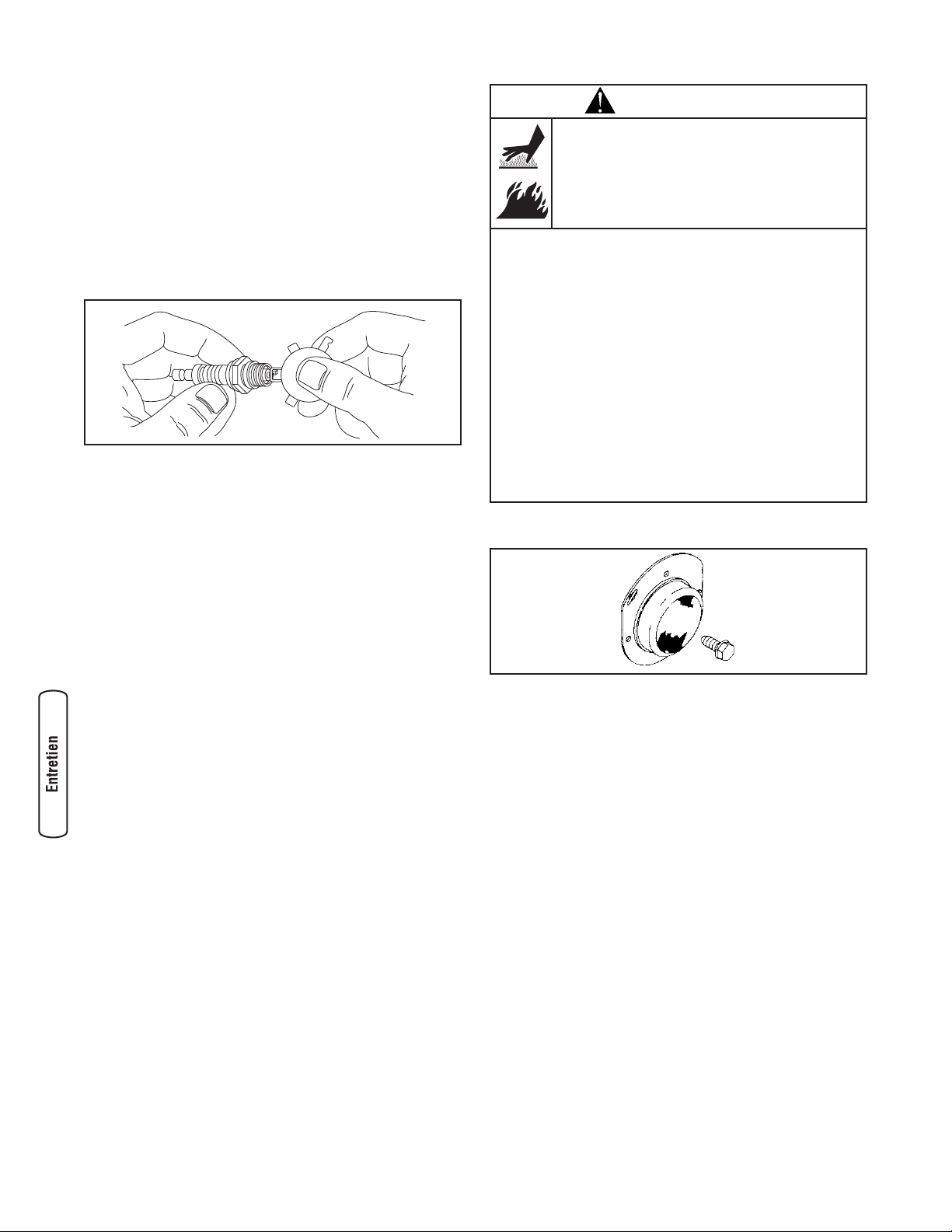
18 BRIGGSandSTRATTON.COM
Entretien de la bougie d'allumage
Changez la bougie d'allumage à toutes les 100 heures
d'utilisation ou une fois par an, le premier des deux
prévalant. Ainsi, le moteur démarrera plus facilement et
fonctionnera mieux.
1. Nettoyez la surface autour de la bougie d'allumage.
2. Enlevez la bougie d'allumage et examinez-la.
3. Vérifiez l'écartement des électrodes à l'aide d'une jauge
d'épaisseur et si nécessaire, réglez l'écartement à
0,76 mm (0,03 po).
4. Si les électrodes sont usés ou si la porcelaine est
craquée ou écaillée. Utilisez la bougie de remplacement
recommandée. Consultez Spécifications.
5. Installez la bougie d'allumage et serrez-la solidement.
Nettoyage de l'écran pare-étincelles
Le silencieux du moteur peut être doté d'un écran pareétincelles. S'il en est doté, vérifiez et nettoyez cet écran à
toutes les 50 heures d'utilisation ou une fois par an, le premier
des deux prévalant.
Si vous utilisez votre pompe de transfert d’eau sur un terrain
boisé, couvert de broussailles ou gazonné non défriché, vous
devez avoir un pare-étincelles. Le propriétaire/opérateur doit
conserver le pare-étincelles en bon état.
Si le moteur fonctionne depuis un certain temps, le
silencieux peut être très chaud. Laissez le silencieux refroidir
avant d'effectuer l'entretien du pare-étincelles.
1. Enlevez l'écran de pare-étincelles pour procéder au
nettoyage et à l'inspection.
2. Vérifiez l’écran et remplacez-le s’il est tordu, troué ou
autrement endommagé. N’utilisez PAS un écran
défectueux. Si l’écran n’est pas endommagée, nettoyezle avec du dissolvant commercial.
3. Replacez l’écran de pare-étincelles sur le silencieux.
REMARQUE: Vous pouvez acheter un nouvel écran de pareétincelles en contacter votre local centre de maintenance de
Briggs & Stratton.
Système de refroidissement à air
Avec le temps, les débris peuvent s’accumuler dans les
ailettes de refroidissement du cylindre et ne peuvent être
repérés que par un désassemblage partiel du moteur. Nous
vous recommandons donc de demander à un distributeur de
service qualifié de nettoyer le système de refroidissement
aux intervalles recommandés (consultez la section Calendrier
d'entretien figurant au début de la section Entretien). Il est
aussi important de garder la partie supérieure du moteur
libre de débris. Consultez Nettoyage.
AVERTISSEMENT
Tout contact avec la zone du silencieux peut
causer des brûlures graves.
La chaleur et les gaz d’échappement peuvent
enflammer des matériaux combustibles et les
structures ainsi que causer des dommages au
réservoir d’essence et entraîner un incendie.
• NE touchez PAS aux pièces chaudes et évitez le contact avec les
gaz d’échappement.
• Laissez l'équipement refroidir avant de le toucher.
• Laissez un dégagement d’au moins 1,5 m (5 pi) tout autour de
la pompe de transfert d’eau, y compris au-dessus.
• Le Code of Federal Regulation (CFR) Title 36 Parks, Forests, and
Public Property exige que de l’équipement alimenté par un
moteur à combustion interne soit doté d’un pare-étincelles et
constamment maintenu en bon état fonctionnement,
conformément à la norme de service 5100-1C de la USDA
Forest ou à une révision de celle-ci. Dans l’État de la Californie,
un pare-étincelles est requis en vertu de la section 4442 du
California Public Resources Code. Il se peut que d’autres États
aient des lois semblables.aux terres fédérales. Si vous équipez le
silencieux d'un pare-étincelles, il doit être en bon état de
fonctionnement.
Page 67
19
Français
Entreposage
Il est préférable de démarrer la pompe de transfert d’eau au
moins une fois tous les sept jours et de la laisser fonctionner
durant au moins 30 minutes. Si cela n'est pas possible et que
vous devez l'entreposer durant plus de 30 jours, suivez les
directives ci-après pour préparer l'unité en vue de l'entreposage.
Directives d'entreposage à long terme
Pendant la période d'entreposage, il est important d'empêcher
la formation de dépôts de gomme dans les parties
importantes du système d'alimentation comme le carburateur,
le filtre à essence, le tuyau souple de carburant ou le réservoir.
De plus, l'expérience a démontré que les carburants à l'alcool
(appelés gazohol, éthanol ou méthanol) attire l'humidité, ce
qui entraîne la séparation et la formation d'acides durant
l'entreposage. Un carburant acide peut endommager le
système d'alimentation du moteur pendant l'entreposage.
Protection du système d’alimentation
Additif de carburant :
Le carburant peut être éventé après un entreposage de plus
de 30 jours. Un carburant éventé cause la formation de
dépôts acides et de gomme dans le système d’alimentation
ou sur les pièces essentielles du carburateur. Pour garder
l’essence propre, utilisez le stabilisateur d’essence FRESH
START™ de Briggs & Stratton, disponible sous forme
d’additif liquide ou cartouche de liquide concentré.
Il est inutile de vidanger le carburant du moteur si vous ajoutez
un stabilisateur d’essence conformément aux directives. Faites
tourner le moteur pendant 2 minutes pour faire circuler le
stabilisateur dans le système de carburant. Vous pouvez
ensuite entreposer le moteur et l’essence durant une période
maximale de 24 mois.
Si le carburant du moteur n’a pas été traité avec un
stabilisateur d’essence, vous devez le vidanger dans un
contenant approuvé. Faites tourner le moteur jusqu’à ce qu’il
s’arrête par manque d’essence. Il est recommandé d’utiliser
du stabilisateur d’essence dans le contenant d’entreposage
pour en conserver la fraîcheur.
Changement de l'huile
Alors que le moteur est encore chaud, vidangez l'huile du carter.
Remplissez le carter à nouveau avec de l'huile de la qualité
recommandée. Consultez la section Changement d'huile.
Huilage de l'alésage du cylindre
• Enlevez la bougie d’allumage et versez environ 15 ml
(1/2 once) d’huile à moteur neuve dans le cylindre.
• Installez la bougie d'allumage et tirez lentement la
poignée du démarreur pour distribuer l’huile.
Pompe de transfert d’eau
1. Vidangez la pompe de transfert d’eau de la manière
décrite dans Vidange et rinçage de la pompe de
transfert d’eau.
2. Nettoyez la pompe de transfert d’eau de la façon décrite
dans Nettoyage.
3. Vérifiez si les ouvertures de la pompe de transfert d’eau
sont ouvertes et libres.
Autres conseils d'entreposage
1. N’entreposez PAS d’essence d’une saison à l’autre à
moins qu’elle ne soit traitée tel que décrit dans
Protection du système d’alimentation.
2. Remplacez le contenant à essence s’il commence à
rouiller. Un carburant contaminé peut causer des
problèmes de moteur.
3. Couvrez l’appareil à l’aide d’une housse de protection
adéquate qui ne retient pas l’humidité.
4. Entreposez la pompe de transfert d’eau dans un endroit
propre et sec.
AVERTISSEMENT
L'essence et ses vapeurs sont extrêmement
inflammables et explosives.
Le feu ou l'explosion risque de provoquer des
blessures graves, pouvant être fatales.
LORSQUE VOUS ENTREPOSEZ L'ESSENCE OU UN ÉQUIPEMENT
AVEC UN RÉSERVOIR À ESSENCE
• Entreposez-le loin des appareils de chauffage, des fours, des
chauffe-eau, des sécheuses ou de tout autre appareil
électroménager disposant d'une veilleuse ou de toute autre
source d'inflammation risquant d'enflammer les vapeurs
d'essence.
LORS DE L'VIDANGE DU CARBURANT
• Éteignez le pompe de transfert d’eau et laissez-le refroidir au
moins 2 minutes avant de retirer le capuchon du réservoir de
carburant. Desserrez lentement le capuchon pour laisser la
pression s'échapper du réservoir.
• Vidangez le réservoir d'essence à l'extérieur.
• Éloignez l'essence des étincelles, des flammes, des veilleuses,
de la chaleur et de toute autre source d'inflammation.
• N'ALLUMEZ PAS de cigarette ou ne fumez pas à proximité de
l'appareil.
AVERTISSEMENT
Unintentional peut résulter dans feu ou
électrique.
• Ne tirez JAMAIS la poignée du démarreur si la bougie
d'allumage est enlevée.
AVERTISSEMENT
Les couvertures de rangement peuvent être
inflammables.
• NE placez JAMAIS une couverture de rangement sur un pompe
de transfert d’eau.
• Laissez l’appareil refroidir suffisamment avant de placer la
couverture de rangement dessus.
Page 68

20 BRIGGSandSTRATTON.COM
Dépannage
Problèm Cause Solution
Peu ou pas de débit lorsque
la pompe fonctionne.
1. La pompe n'est pas amorcée.
2. Le boyau d'aspiration est obstrué, écrasé,
endommagé, trop long ou son diamètre
est trop petit.
3. Le panier-filtre n'est pas complètement
sous l'eau.
4. Il y a une fuite d'air au niveau du
connecteur du boyau d'aspiration.
5. Le panier-filtre est bouché.
6. Le boyau d'évacuation est obstrué,
endommagé, trop long ou son diamètre
est trop petit.
7. Hauteur excessive ou marginale.
8. Le levier du régime du moteur est à la
position "Slow".
1. Remplir la chambre de pompe avec
l'eau et amorcez la pompe.
2. Remplacez le boyau d'aspiration.
3. Immergez le panier-filtre et l'extrémité
du boyau d'aspiration complètement
sous l'eau.
4. Remplacez la rondelle d'étanchéité si elle
est manquante ou endommagée. Serrez
le connecteur et la bride du boyau.
5. Nettoyez les débris dans le panier-filtre.
6. Remplacez le boyau d'évacuation.
7. Changez la pompe et/ou les boyaux
d'endroit pour réduire la hauteur.
8. Déplacez le levier du régime du moteur
à la position "Fast".
Le moteur ne démarre pas;
manque de puissance;
démarre et a des ratés; ou a
des "à-coups" ou des
hésitations.
1. Interrupteur à bascule réglé sur "Off".
2. Vanne de combustible en position "Off".
3. Filtre à air encrassé.
4. Panne d'essence.
5. Essence éventée ou contaminée ou eau
dans l'essence.
6. Câble de bougie non branché à la bougie
d'allumage.
7. Bougie défectueuse.
8. Trop grande quantité d'essence dans le
mélange air/essence, ce qui "noie" le
moteur.
9. L’ajustement du carburateur n’est pas
adéquat.
1. Réglez l'interrupteur sur "On".
2. Tournez la vanne de combustible à la
position "On".
3. Nettoyez ou remplacez le filtre à air.
4. Attendez deux minutes et remplissez le
réservoir d'essence.
5. Vidangez le réservoir et le carburateur;
faites le plein avec de l'essence
nouvelle.
6. Branchez le fil à la bougie.
7. Remplacez la bougie.
8. Attendez 5 minutes et redémarrez le
moteur.
9. Contactez un centre de service autorisé.
Le moteur s'arrête quand il
fonctionne.
Panne d'essence. Attendez deux minutes et remplissez le
réservoir d'essence.
Page 69

21
Français
Garanties
Garantie du dispositif antipollution
Briggs & Stratton Corporation (B&S), le California Air
Resources Board (CARB) et le United States Environmental
Protection Agency (U.S. EPA)
Énoncé de garantie du dispositif antipollution (Droits et
obligations du propriétaire relatifs à la garantie contre les
défauts)
Énoncé de garantie du dispositif antipollution pour la
Californie, les États-Unis et le Canada
Le California Air Resources Board (CARB), l'U.S. EPA et B&S
sont heureux de vous expliquer la garantie couvrant le
dispositif antipollution de votre petit moteur hors route. En
Californie, les nouveaux modèles de petits moteurs hors
route de l'année 2006 et ultérieurs doivent être conçus,
construits et équipés de façon à respecter les normes antismog rigoureuses de l'état. Ailleurs aux États-Unis, les
nouveaux moteurs à étincelles hors route homologués,
modèles 1997 ou plus récents, doivent respecter des normes
semblables définies par l'U.S. EPA. B&S doit garantir le
dispositif antipollution de votre moteur pour les périodes
indiquées ci-dessous, à condition qu'il n'y ait pas eu d'abus,
de négligence, de mauvais entretien sur ledit moteur.
Votre dispositif antipollution comprend des pièces comme le
carburateur, le filtre à air, le système d'allumage, le conduit
d'essence, le silencieux et le convertisseur catalytique. Il
peut aussi y avoir des connecteurs et d'autres dispositifs
reliés aux émissions.
Dans le cas d'un défaut couvert par la garantie, B&S réparera
votre petit moteur hors route sans frais, et ce, incluant le
diagnostic, les pièces et la main d'œuvre.
Couverture de garantie contre les défauts du dispositif
antipollution de Briggs & Stratton
La garantie de votre petit moteur hors route couvre les
pièces défectueuses du dispositif antipollution pour une
période de deux ans, sujette aux dispositions détaillées cidessous. Si une pièce de votre moteur couverte par la
garantie est défectueuse, B&S la réparera ou la remplacera.
Responsabilités de la garantie du propriétaire
En tant que propriétaire de petit moteur hors route, vous
êtes responsable de l'exécution de l'entretien requis indiqué
dans vos instructions d'utilisation et d'entretien. B&S
recommande de conserver tous les reçus reliés à l'entretien
de votre petit moteur hors route; toutefois, B&S ne peut
refuser la garantie uniquement parce que vous êtes dans
l'impossibilité de produire les reçus ou que vous n'avez pas
effectué toutes les étapes de l'entretien prévu.
Néanmoins, vous devez savoir, en tant que propriétaire de petit
moteur hors route, que B&S peut renier la garantie si votre
moteur ou une pièce font défaut en raison d'abus, de négligence,
d'entretien inadéquat ou de modifications non approuvées.
Dès qu'un problème survient, vous avez la responsabilité de
faire examiner votre moteur chez un distributeur de service
B&S autorisé. Les réparations couvertes par la garantie non
contestées doivent être effectuées dans un délai raisonnable,
n'excédant pas 30 jours.
Si vous avez des questions au sujet de vos droits et
responsabilités reliés à la garantie, veuillez communiquer
avec un représentant de B&S au 1-414-259-5262.
La garantie du dispositif antipollution est une garantie contre
les défauts. Les défauts sont évalués selon la performance
normale du moteur. La garantie n'est pas reliée à un test du
dispositif antipollution à l'usage.
Dispositions de la garantie contre les défauts du dispositif
antipollution de Briggs & Stratton
Les dispositions qui suivent sont spécifiques à la couverture
de garantie contre les défauts du dispositif antipollution. Elle
est un ajout à la garantie sur les moteurs de B&S pour les
moteurs non régulés, figurant dans le manuel d'utilisation.
1. Pièces garanties
La couverture de cette garantie n'englobe que les
pièces énumérées ci-dessous (pièces du dispositif
antipollution) dans la mesure où ces pièces étaient
présentes sur le moteur au moment de l'achat.
a. Système de contrôle d'alimentation en carburant
• Dispositif d'enrichissement pour démarrage à
froid (étrangleur à glissement)
• Carburateur et pièces internes
• Pompe à carburant
• Conduit d'essence, raccords de conduit
d'essence, brides de serrage
• Réservoir d'essence, bouchon et attache
• Absorbeur de vapeurs d’essence
b. Circuit d'entrée d'air
• Filtre à air
• Collecteur d'admission
• Ligne de purge et d’évacuation
c. Système d'allumage
• Bougie(s) d'allumage
• Système d'allumage à magnéto
d. Système de catalyseur
• Catalytic converter
• Collecteur d'échappement
• Système d'injection d'air ou soupape d'impulsion
e. Éléments divers utilisés dans les systèmes
précédemment mentionnés
• Soupapes et interrupteurs de dépression, de
température, de position, à délai critique
• Connecteurs et dispositifs
Page 70

22 BRIGGSandSTRATTON.COM
2. Durée de la couverture
B&S garantit au propriétaire initial et à tous les
acheteurs ultérieurs que les pièces garanties seront
libres de tout défaut de matériel et de main d'œuvre qui
pourrait entraîner la défectuosité des pièces garanties,
et ce, pour une période de deux ans à compter de la
date de livraison du moteur à un acheteur au détail.
3. Aucun frais
La réparation ou le remplacement de toute pièce
garantie s'effectuera sans frais pour le propriétaire, y
compris la main d'œuvre reliée au diagnostic concluant
qu'une pièce garantie est effectivement défectueuse, si
le diagnostic est effectué chez un distributeur de
service B&S approuvé. Pour obtenir des services en
vertu de la garantie sur les émissions, veuillez appelez
le distributeur de service autorisé de B&S le plus près
de chez vous. Vous le trouverez dans les "Pages
Jaunes" sous "Moteurs, essence", "Essence, moteurs",
"Tondeuses à gazon" ou une catégorie similaire.
4. Réclamations et exclusions de couverture
Les réclamations au titre de la garantie doivent être
présentées conformément aux dispositions de la
politique de garantie du moteur de B&S. La couverture
de garantie n'englobe pas les défectuosités sur des
pièces garanties qui ne sont pas les pièces originales
de B&S ou les défectuosités reliées à un abus, de la
négligence ou un entretien inapproprié tel que détaillé
dans la politique de garantie du moteur de B&S. B&S
n'a pas la responsabilité de couvrir les défectuosités
des pièces garanties causées par l'utilisation de pièces
ajoutées, non originales ou modifiées.
5. Entretien
Toute pièce garantie dont le remplacement n'est pas
prévu dans l'entretien requis, ou qui ne doit faire l'objet
que d'une inspection régulière et qu'il ne faut que "
réparer ou remplacer au besoin ", est garantie contre
les défectuosités pour la durée de la période de
garantie. Toute pièce garantie dont le remplacement fait
partie de l'entretien requis est garantie contre les
défauts seulement pour la période se terminant au
premier remplacement prévu de ladite pièce. Toute
pièce de rechange dont la performance et la durabilité
sont équivalentes peut être utilisée pour l'entretien ou
les réparations. Le propriétaire est responsable de
l'exécution de l'entretien requis, indiqué dans le manuel
d'utilisation de B&S.
6. Couverture indirecte
La couverture prévue aux présentes englobe toute
défectuosité de l'un des composants du moteur causée
à la suite d'une défectuosité d'une des pièces garanties
encore couverte par la garantie.
Renseignements sur les émissions
Les renseignements concernant la période de durabilité des
émissions et l’indice de pollution atmosphérique doivent être
fournis avec les moteurs qui répondent aux normes relatives
aux émissions de catégorie 2 de la California Air Resources
Board (CARB). Le fabricant du moteur doit fournir ces
renseignements aux consommateurs sur des étiquettes
d’émissions. L’étiquette des émissions du moteur fournit des
renseignements sur la certification.
La période de durabilité des émissions décrit le nombre
d’heures pendant lesquelles le moteur peut fonctionner en
respectant les normes relatives aux émissions, en supposant
que l’entretien est effectué conformément aux directives de
fonctionnement et d’entretien. Les catégories utilisées sont
les suivantes:
Modéré : Le moteur peut fonctionner pendant 125 heures
tout en respectant la norme relative aux émissions.
Intermédiaire : Le moteur peut fonctionner pendant 250
heures tout en respectant la norme relative aux émissions.
Prolongé : Le moteur peut fonctionner pendant 500 heures
tout en respectant la norme relative aux émissions.
Par exemple, l’utilisation d’une tondeuse poussée est
d’environ 20 à 25 heures par année. Par conséquent, la
période de durabilité des émissions d’un moteur de
catégorie intermédiaire équivaut à une période de 10 à 12
années.
Certains moteurs respecteront les normes relatives aux
émissions de phase 2 de la United States Environmental
Protection Agency (USEPA). Dans le cas des moteurs
homologués phase 2, la période de conformité des
émissions indiquée sur l’étiquette de conformité des
émissions indique le nombre d’heures de fonctionnement
pendant lesquelles le moteur a démontré qu’il respectait les
exigences fédérales en matière d’émissions.
Pour les moteurs de cylindrée inférieure à 225 cc:
Catégorie C = 125 heures
Catégorie B = 250 heures
Catégorie A = 500 heures.
Pour les moteurs de cylindrée égale ou supérieure à 225 cc:
Catégorie C = 250 heures
Catégorie B = 500 heures
Catégorie A = 1000 heures.
Page 71

23
Français
GARANTIE DU PROPRIÉTAIRE D'UNE POMPE À EAU DE BRIGGS & STRATTON POWER PRODUCTS GROUP, LLC
GARANTIE LIMITÉE
Briggs & Stratton Power Products Group, LLC réparera ou remplacera, sans frais, toutes pièces défectueuses de la pompe à eau comportant un vice de
matériau ou un défaut de fabrication ou les deux. En vertu de la présente garantie, les frais de transport des produit soumises pour réparation ou
remplacement sont à la charge de l'acheteur. La présente garantie sera en vigueur durant les périodes stipulées ci-dessous et est assujettie aux
conditions stipulées ci-dessous. Pour obtenir des services en vertu de la garantie, veuillez consulter notre Outil de recherche d'un Service après-vente
agréé au http://www.BRIGGSandSTRATTON.COM afin de trouver un distributeur de service après-vente agréé dans votre région.
IL N'EXISTE AUCUNE AUTRE GARANTIE EXPRESSE. LES GARANTIES IMPLICITES, INCLUANT CELLES DE QUALITÉ MARCHANDE ET D'ADAPTATION À
UN USAGE PARTICULIER, SONT LIMITÉES À UNE PÉRIODE D'UN AN À PARTIR DE LA DATE D'ACHAT OU JUSQU'À LA LIMITE PERMISE PAR LA LOI,
TOUTE GARANTIE IMPLICITE EST EXCLUE. LA RESPONSABILITÉ POUR DOMMAGES ACCESSOIRES OU INDIRECTS EST EXCLUE DANS LA MESURE
OÙ UNE TELLE EXCLUSION EST PERMISE PAR LA LOI. Certains États/provinces ou pays n'autorisent aucune restriction sur la durée d'une garantie
implicite, et certains États/provinces ou pays n'autorisent pas l'exclusion ou la limitation des dommages consécutifs ou indirects. Par conséquent, les
restrictions et exclusions décrites ci-dessus pourraient ne pas s'appliquer dans votre cas. La présente garantie vous accorde certains droits légaux
spécifiques et vous pourriez également en avoir d'autres, qui peuvent varier d'un État ou d'une province à l'autre et d'un pays à l'autre.
2 ans
1 an
Usage par un consommateur
Usage à des fins commerciales
La période de garantie débute à la date d'achat par le premier acheteur au détail ou par le premier utilisateur commercial final, et se prolonge pour la durée
stipulée ci-dessus. " Usage par un consommateur " signifie utilisation domestique personnelle dans une résidence, par l'acheteur au détail. " Usage à des fins
commerciales " signifie toute autre utilisation, y compris à des fins commerciales, de génération de revenus ou de location. Aux fins de la présente garantie,
dès qu'un équipement a été utilisé commercialement une fois, il est par la suite considéré comme étant d'usage à des fins commerciales.
POUR EXERCER LA GARANTIE SUR TOUT PRODUIT FABRIQUÉ PAR BRIGGS & STRATTON, IL N'EST PAS NÉCESSAIRE DE L'ENREGISTRER. CONSERVEZ
LE REÇU COMME PREUVE D'ACHAT. SI, LORS D'UNE RÉCLAMATION DE GARANTIE, VOUS NE POUVEZ PROUVER LA DATE INITIALE DE L'ACHAT, NOUS
UTILISERONS LA DATE DE FABRICATION DU PRODUIT COMME DATE DE RÉFÉRENCE POUR DÉTERMINER LA PÉRIODE DE GARANTIE.
À PROPOS DE LA GARANTIE
Nous acceptons de faire effectuer les réparations couvertes par la garantie et tenons à nous excuser pour tout inconvénient subi. Tout agent d'un service
après-vente agréé peut exécuter les réparations couvertes par la garantie. La plupart des réparations couvertes par la garantie sont traitées automatiquement;
cependant, il arrive parfois que les demandes de service en vertu de la garantie soient non fondées. Par exemple, la garantie ne couvre pas les dommages
causés à l'équipement par une utilisation abusive, par un manque d'entretien périodique, durant l'expédition, la manutention ou l'entreposage, ou en raison
d'une installation inadéquate. De même, la garantie sera annulée si la date de fabrication ou le numéro de série apposé à la pompe à eau ou au moteur a été
enlevé ou si l'équipement a été changé ou modifié. Durant la période de garantie, le distributeur de service après-vente agréé réparera ou remplacera, à son
gré, toute pièce qui, après examen, est trouvée défectueuse à la suite d'une utilisation et d'un entretien normaux. La présente garantie ne couvre pas les
réparations et les équipements suivants
• Usure normale: Comme tout autre dispositif mécanique, les groupes électrogènes d'extérieur nécessitent l'entretien périodique de certaines pièces
pour fonctionner adéquatement. La présente garantie ne couvre pas les frais de réparation des pièces ou des équipements dont la durée de vie utile a
été dépassée à la suite d'une utilisation normale.
• Installation et entretien: La présente garantie ne couvre pas les équipements ou les pièces qui ont fait l'objet d'une installation ou de modifications et
de changements inadéquats ou non autorisés, d'une mauvaise utilisation, de négligence, d'un accident, d'une surcharge, d'emballement, d'entretien
inadéquat, de réparation ou d'entreposage qui, selon nous, auraient nui à la performance et à la fiabilité du produit. De plus, la garantie ne couvre pas
l'entretien normal tel que les filtres à air, le réglage, le nettoyage du circuit d'alimentation et son obstruction (causée par l'accumulation de produits
chimiques, de saletés, etc.).
• Exclusions supplémentaires: La présente garantie exclut les pièces qui s'usent tels que les joints d'étanchéité et les joints toriques, etc. La présente
garantie exclut également les pompes ayant fonctionné sans alimentation en eau, soumise au gel ou à une détérioration chimique. Cette pompe est
garantie pour une utilisation dans des applications reliées à l'eau claire, puisque certains composants subiront une usure accélérée variant selon le
pourcentage et le niveau d'abrasion des dépôts passant dans la pompe. Les pièces accessoires telles que les boyaux ou les filtres ne sont pas
couvertes par la garantie du produit. Cette garantie exclut toute défaillance due à une catastrophe naturelle ou à toute autre force majeure hors du
contrôle du fabricant. 198260F, Rev. C, 12/31/2006
BRIGGS & STRATTON POWER PRODUCTS GROUP, LLC
JEFFERSON, WI, USA
PÉRIODE DE GARANTIE
À partir du 1er septembre 2005, la présente garantie remplace toute garantie non datée et toute garantie dont la date est antérieure au 1er septembre 2005.
Page 72

24 BRIGGSandSTRATTON.COM
Briggs & Stratton Power Products Group, LLC
900 N. Parkway
Jefferson, Wisconsin, 53549 U.S.A.
Puissance nominale: La puissance nominale brute des modèles avec moteur à essence est indiquée sur une étiquette, conformément au
code J1940 (Small Engine Power & Torque Rating Procedure) de la SAE (Society of Automotive Engineers), et la performance nominale a été
obtenue et corrigée conformément au code J1995 (révision 05-2002) de la SAE. Les valeurs de couple ont été mesurées à 3 060 tr/min; les
valeurs de puissance ont été mesurées à 3 600 tr/min. La puissance brute réelle du moteur sera inférieure et sera affectée, entre autres
choses, par les conditions de fonctionnement ambiantes ainsi que par les différents entre moteurs. Étant donné la vaste gamme de produits
sur lesquels nos moteurs sont installés, ainsi que la variété de problèmes environnementaux reliés au fonctionnement de l’équipement, il est
possible que le moteur à essence que vous avez acheté ne développe pas la puissance nominale brute indiquée lorsqu’il est utilisé pour
entraîner un appareil électrique donné (puissance « sur site » ou net réelle). Cette différence est causée par différents facteurs dont, entre
autres, les accessoires (filtre à air, échappement, chargement, refroidissement, carburateur, pompe à essence, etc.), les limites de l’appareil,
les conditions de fonctionnement ambiante (température, humidité, l’altitude) et les différences entre moteurs. En raison des limites de
fabrication et de capacité, Briggs & Stratton peut substituer un moteur de plus grande puissance pour un moteur de cette série.
(800) 743-4115
Pompe de transfert d’eau
Caractéristiques du produit
Modèle 073019
Diamètre de l'orifice d'aspiration . . . . . . . . . . 50 mm (2 po)
Diamètre de l'orifice d'évacuation . . . . . . . . . . 50 mm (2 po)
Hauteur totale . . . . . . . . . . . . . . . . . . . . . . . . . 32 m (106 pi)
Hauteur maximale
Hauteur géométrique d'aspiration . . . . . . . . . . 8 m (25 pi)
Hauteur géométrique d'évacuation . . . . . . . . 25 m (81 pi)
Capacité maximale
d'évacuation . . . . 586 l (155 gallons américains) par minute
Poids à l'expédition . . . . . . . . . . . . . . . . . . . . . .32 kg (70 lb)
Cylindrée . . . . . . . . . . . . . . . . . . . . . . . . . .190 cc (11,57 po)
Écartement des électrodes . . . . . . . . . . .0,76 mm (0.030 po)
Capacité du réservoir d'essence . .3,78 l (1 gallon américain)
Capacité du carter d'huile . . . . . . . . . . . . . . .0,6 l (20 onces)
Modèle 073020
Diamètre de l'orifice d'aspiration . . . . . . . . . . 76 mm (3 po)
Diamètre de l'orifice d'évacuation . . . . . . . . . . 76 mm (3 po)
Hauteur totale . . . . . . . . . . . . . . . . . . . . . . . . . 32 m (106 pi)
Hauteur maximale
Hauteur géométrique d'aspiration . . . . . . . . . . 8 m (25 pi)
Hauteur géométrique d'évacuation . . . . . . . . 25 m (81 pi)
Capacité maximale
d'évacuation . . . . 908 l (240 gallons américains) par minute
Poids à l'expédition . . . . . . . . . . . . . . . . . . . . . .38 kg (82 lb)
Cylindrée . . . . . . . . . . . . . . . . . . . . . . . . . .190 cc (11,57 po)
Écartement des électrodes . . . . . . . . . . .0,76 mm (0,030 po)
Capacité du réservoir d'essence . .3,78 l (1 gallon américain)
Capacité du carter d'huile . . . . . . . . . . . . . . .0,6 l (20 onces)
Pièces d’entretien courant
Filtre à air . . . . . . . . . . . . . . . . . . . . . . . . . . . . . . . . . .696263
Bougie antiparasite . . . . . . . . . . . . . . . . . . . . . . . . . .491055S
Bouteille d’huile à moteur . . . . . . . . . . . . . . . . . . . . . .100005
Stabilisateur d’essence . . . . . . . . . . . . . . . .100002 or 5041D
Pare-étincelles . . . . . . . . . . . . . . . . . . . . . . . . . . . . . .398067
 Loading...