

Page 1
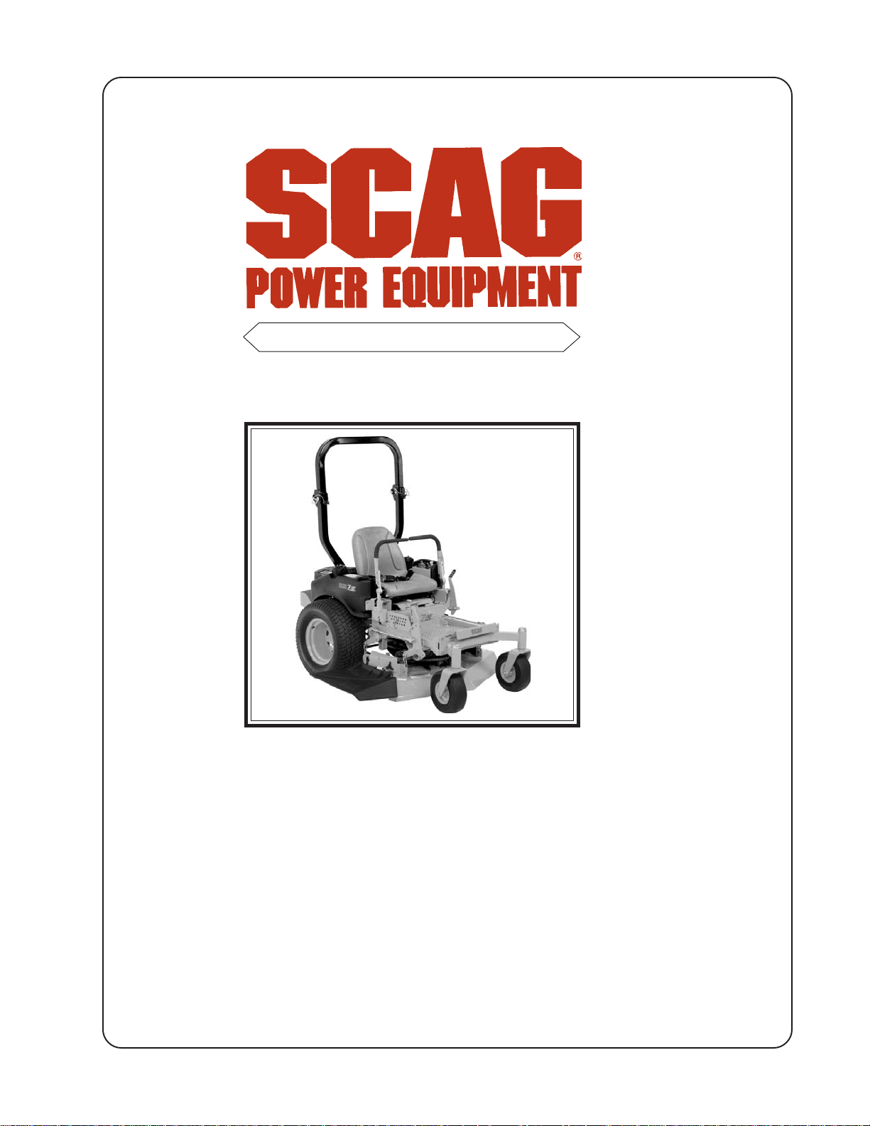
MODEL SZC
OPERATOR’S MANUAL
THIS MANUAL CONTAINS THE OPERATING
INSTRUCTIONS AND SAFETY INFORMATION FOR YOUR SCAG MOWER. READING
THIS MANUAL CAN PROVIDE YOU WITH
ASSISTANCE IN MAINTENANCE AND ADJUSTMENT PROCEDURES TO KEEP YOUR
MOWER PERFORMING TO MAXIMUM EFFICIENCY. THE SPECIFIC MODELS THA T THIS
BOOK COVERS ARE CONTAINED ON THE
INSIDE COVER. BEFORE OPERA TING YOUR
MACHINE, PLEASE READ ALL THE INFORMATION ENCLOSED.
© 2005
SCAG POWER EQUIPMENT
DIVISION OF MET ALCRAFT OF MA YVILLE, INC.
P ART NO. 03169
PRINTED 8/05
PRINTED IN USA
Page 2

WARNING:
FAILURE TO FOLLOW SAFE OPERATING PRACTICES
MAY RESULT IN SERIOUS INJURY.
* Keep all shields in place, especially the grass discharge chute.
* Before performing any maintenance or service, stop the machine and
remove the spark plug wire and ignition key.
* If a mechanism becomes clogged, stop the engine before cleaning.
* Keep hands, feet and clothing away from power-driven parts.
* Read this manual completely as well as other manuals that came
with your mower.
* Keep others off the tractor (only one person at a time)
REMEMBER - YOUR MOWER IS ONLY AS SAFE AS THE OPERATOR!
Hazard control and accident prevention are dependent upon the awareness,
concern, prudence, and proper training of the personnel involved in the
operation, transport, maintenance, and storage of the equipment.
This manual covers the operating instructions
and illustrated parts list for:
SZC36A-16HN with a serial number of B3900001 to B3999999
SZC36A-17KAI with a serial number of B4000001 to B4099999
SZC36A-19KAI with a serial number of B4100001 to B4199999
SZC42A-19KAI with a serial number of B4400001 to B4499999
SMZC-36A with a serial number of B4600001 to B4699999
SMZC-42A with a serial number of B4700001 to B4799999
Always use the entire serial number listed on the serial number
tag when referring to this product.
Page 3

TABLE OF CONTENTS
SUBJECT PAGE
Section 1 - General Information
1.1 Introduction .............................................................................................................................1
1.2 Directional Reference .............................................................................................................1
1.3 Servicing the Engine and Drive Train Components ................................................................1
1.3 Symbols ............................................................................................................................... 2-3
Section 2 - Safety Information
2.1 Introduction .............................................................................................................................4
2.2 Signal W ords ...........................................................................................................................4
2.3 Before Operation Considerations ...........................................................................................4
2.4 Operation Considerations ........................................................................................................5
2.5 Roll Over Protection System (Optional) .................................................................................7
2.6 Maintenance Considerations ...................................................................................................9
2.7 Safety and Instructional Decals ............................................................................................10
Section 3 - Specifications ....................................................................................................11-12
Section 4 - Operating Instructions
4.1 Controls and Instrument Identification..................................................................................13
4.2 Safety Interlock System ........................................................................................................14
4.3 Initial Run-In Procedures ......................................................................................................15
4.4 Starting the Engine................................................................................................................15
4.5 Ground Travel and Steering ..................................................................................................15
4.6 Engaging the Deck Drive .....................................................................................................16
4.7 Hillside Operation .................................................................................................................17
4.8 Parking the Mower ...............................................................................................................17
4.9 After Operation ....................................................................................................................17
4.10 Removing Clogged Material .................................................................................................18
4.1 1 Moving Mower with Engine Stopped ...................................................................................18
4.12 Recommendations for Mowing .............................................................................................18
4.13 Adjusting Cutting Height.......................................................................................................18
4.14 Adjusting the Steering Levers...............................................................................................19
Section 5 - Troubleshooting Cutting Conditions .............................................................. 20-22
I
Page 4

TABLE OF CONTENTS (CONT'D)
SUBJECT PAGE
Section 6 - Adjustments
6.1 Parking Brake Adjustment....................................................................................................23
6.2 Travel Adjustments ...............................................................................................................24
6.3 Throttle Control and Choke Adjustments..............................................................................25
6.4 Belt Adjustment ....................................................................................................................25
6.5 Belt Alignment ......................................................................................................................25
6.6 Cutter Deck Adjustments .....................................................................................................26
Section 7 - Maintenance
7.1 Maintenance Chart ...............................................................................................................29
7.2 Lubrication Fitting Points ......................................................................................................30
7.3 Hydraulic System..................................................................................................................32
7.4 Engine Oil .............................................................................................................................33
7.5 Engine Fuel System ..............................................................................................................33
7.6 Engine Air Cleaner................................................................................................................34
7.7 Battery ..................................................................................................................................34
7.8 Drive Belts ............................................................................................................................36
7.9 Cutter Blades ........................................................................................................................36
7.10 Tires ......................................................................................................................................37
7.11 Body , Deck and Upholstery..................................................................................................37
Section 8 - Replacement Parts
SZWC36A, 42A Cutter Deck .................................................................................................. 38-39
Cutter Deck Controls................................................................................................................ 40-41
Sheet Metal Components.......................................................................................................... 42-43
SZC Roll Over Protection System............................................................................................ 44-45
Drive System Components ....................................................................................................... 46-47
Engine and Attaching Parts ...................................................................................................... 48-49
Steering Components ................................................................................................................ 50-51
Brake Components ................................................................................................................... 52-53
Fuel and Hydraulic System ....................................................................................................... 54-55
Electrical System ...................................................................................................................... 56-57
Hydraulic Pump (BDP-10A) .................................................................................................... 48-59
Replacement Decals ................................................................................................................. 60-61
Electrical Schematic .......................................................................................................................62
Warranty Statement ............................................................................................. Inside Back Cover
II
Page 5
Section 1
GENERAL INFORMATION
1.1 INTRODUCTION
Your mower was built to the highest standards in the
industry. However, the prolonged life and maximum
efficiency of your mower depends on you following the
operating, maintenance and adjustment instructions in this
manual.
If additional information or service is needed, contact your
Scag Power Equipment Dealer.
We encourage you to contact your dealer for repairs. All
Scag dealers are informed of the latest methods to service
this equipment and provide prompt and efficient service in
the field or at their service shop. They carry a full line of
Scag service parts.
USE OF OTHER THAN ORIGINAL SCAG
REPLACEMENT PARTS WILL VOID THE
WARRANTY.
Scag approved attachments and accessories:
GC-4D (p/n 9054)
GC-4F (p/n 9055)
Mulch Plate (p/n 9281, 9282)
Blade Buddy (p/n 9212)
STC Lights (p/n 9274)
WARNING:
For pictorial clarity , some illustrations and figures
in this manual may show shields, guards or plates
open or removed. Under no circumstances should
your mower be operated without these devices in
place.
All information is based upon product information
available at the time of approval for printing. Scag
Power Equipment reserves the right to make changes
at any time without notice and without incurring any
obligation.
When ordering parts, always give the model and serial
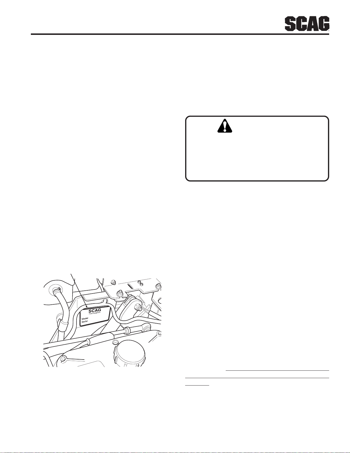
number of your tractor. The serial number plate is located
under the seat as shown in Figure 1-1.
SERIAL NUMBER
PLATE LOCATION
Figure 1-1 T ractor Serial Number Plate Location
USE ONLY SCAG APPROVED ATTACHMENTS
AND ACCESSORIES.
1.2 DIRECTION REFERENCE
The “Right” and “Left”, “Front” and “Rear” of the machine
are referenced from the operator’s right and left when
seated in the normal operating position and facing the
forward travel direction.
1.3 SERVICING THE ENGINE AND DRIVE
TRAIN COMPONENTS
The detail servicing and repair of the engine and hydraulic
pumps are not covered in this manual; only routine
maintenance and general service instructions are provided.
For service of these components during the limited warranty
period, it is important to contact your Scag dealer or find a
local authorized servicing agent of the component
manufacturer.
components during the warranty period may void your
warranty.
Any unauthorized work done on these
Attachments and accessories manufactured by companies
other than Scag Power Equipment are not approved for use
on this machine.
1
Page 6
Section 1
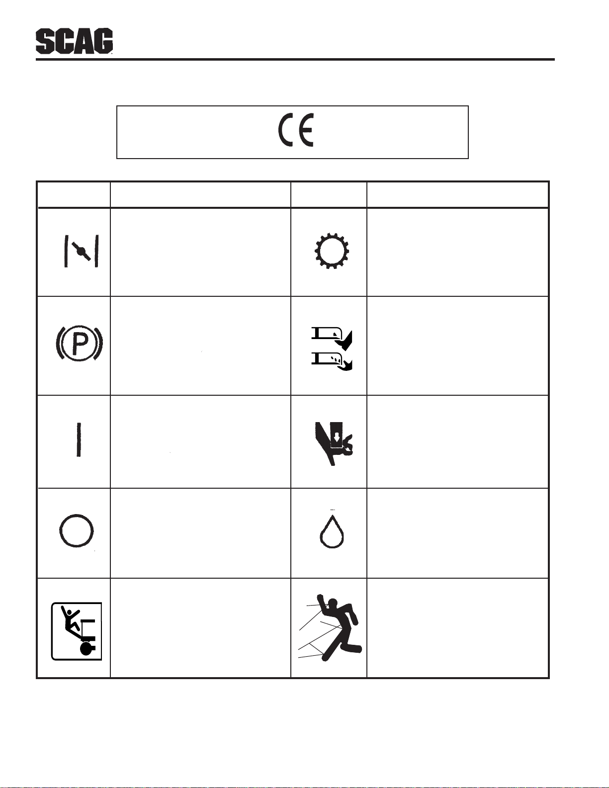
ISO Symbols
SYMBOL DESCRIPTION
Parking Brake
CE Mark
SYMBOL DESCRIPTION
TransmissionChoke
Spinning Blade
48071S
On/Start
Off/Stop
Falling Hazard
WARNING
FALLING HAZARD
USE ONLY SCAG APPROVED
RIDING ATTACHMENTS
SEE OPERATOR'S MANUAL
481109
Spring T ension on Idler
Oil
Thown Object Hazard
2
Page 7
Section 1
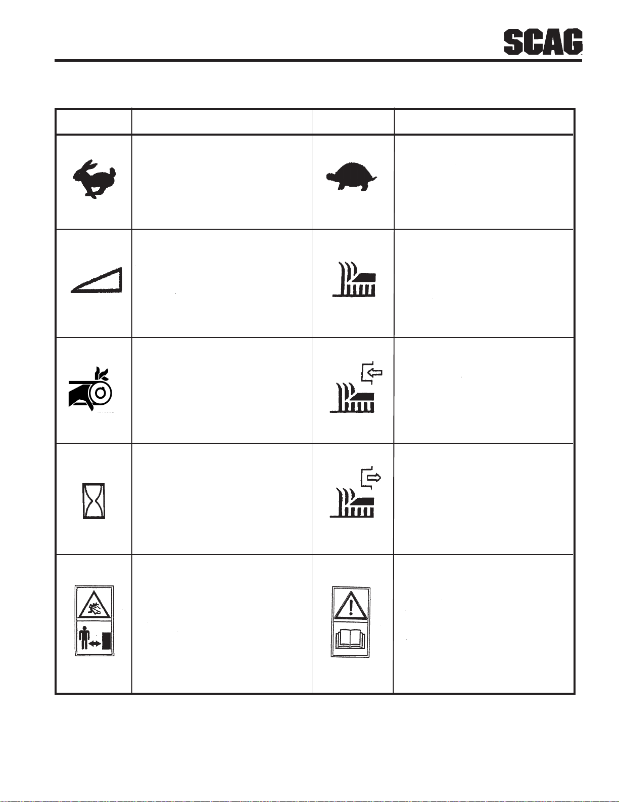
SYMBOL DESCRIPTION SYMBOL DESCRIPTION
481039S
Fast
Continuously V ariable - Linear
Pinch Point
Slow
Cutting Element - Basic symbol
Cutting Element - Engage
Hourmeter/Elapsed Operating Hours
Thown Object Hazard
Keep Bystanders Away
Cutting Element - Disengage
Read Operator's Manual
3
Page 8
2.1 INTRODUCTION
Section 2
SAFETY INFORMATION
Your mower is only as safe as the operator.
Carelessness or operator error may result in serious
bodily injury or death. Hazard control and accident
prevention are dependent upon the awareness, concern,
prudence, and proper training of the personnel involved in
the operation, transport, maintenance and storage of the
equipment.
and thoroughly familiar with all of the controls before
operating the mower. The owner/user can prevent and is
responsible for accidents or injuries occuring to
themselves, other people or property .
READ THIS OPERATOR’S MANUAL BEFORE
ATTEMPTING TO START YOUR MOWER.
A replacement manual is available from your authorized
Scag Service Dealer or by contacting Scag Power
Equipment, Service Department at P.O. Box 152,
Mayville, WI 53050 or via the Internet at
www.scag.com. The manual for your machine can be
downloaded by using the model and serial number or use
the contact form to make your request. Please indicate
the complete model and serial number of your Scag
product when requesting replacement manuals.
Make sure every operator is properly trained
2.2 SIGNAL WORDS
The signal word “DANGER” denotes that an extremely
hazardous situation exists on or near the machine that
could result in high probability of death or irrepairable
injury if proper precautions are not taken.
WARNING:
The signal word “WARNING” denotes that a hazard
exists on or near the machine that can result in injury or
death if proper precautions are not taken.
CAUTION:
The signal word “CAUTION” is a reminder of safety
practices on or near the machine that could result in
personal injury if proper precautions are not taken.
Your safety and the safety of others depends significantly
upon your knowledge and understanding of all correct
operating practices and procedures of this machine.
2.3 BEFORE OPERATION
CONSIDERATIONS
This symbol means “Attention! Become Alert! Your
Safety is Involved!" The symbol is used with the
following signal words to attract your attention to safety
messages found on the decals on the machine and
throughout this manual. The message that follows the
symbol contains important information about safety . T o
avoid injury and possible death, carefully read the
message! Be sure to fully understand the causes of
possible injury or death.
Signal Word:
It is a distinctive word found on the safety decals on the
machine and throughout this manual that alerts the
viewer to the existence and relative degree of the
hazard.
1. NEVER allow children to operate this riding mower.
Do not allow adults to operate this machine without
proper instructions.
2. DO NOT mow when children and/or others are
present. Keep children out of the mowing area and
in the watchful care of a responsible adult other than
the operator. Be alert and turn machine off if a child
enters the area.
3. Clear the area to be mowed of objects that could be
picked up and thrown by the cutter blades.
4. DO NOT carry passengers.
5. DO NOT operate the machine under the influence
of alcohol or drugs.
4
Page 9
Section 2
2.3 BEFORE OPERATION
CONSIDERATIONS (CONT'D)
6. If the operator(s) or mechanic(s) cannot read English
or Spanish, it is the owner's responsibility to explain
this material to them.
7. DO NOT wear loose fitting clothing. Loose
clothing, jewelry or long hair could get tangled in
moving parts. Do not operate the machine wearing
shorts; always wear adequate protective clothing
including long pants. Wearing safety glasses, safety
shoes and a helmet is advisable and is required by
some local ordinances and insurance regulations.
8. Operator hearing protection is recommended,
particularly for continuous operation of the mower.
W ear suitable hearing protection. Prolonged
exposure to loud noise can cause hearing
impairment or loss.
9. Keep the machine and attachments in good operating
condition. Keep all shields and safety devices in
place. If a shield, safety device or decal is defective
or damaged, repair or replace it before operating the
machine.
12. DO NOT add fuel to a running or hot engine. Allow
the engine to cool for several minutes before adding
fuel.
13. Keep flammable objects (cigarettes, matches, etc.),
open flames and sparks away from the fuel tank and
fuel container.
14. Equipment must comply with the latest requirements
per SAE J137 and/or ANSI/ASAE S279 when
driven on public roads.
-NOTE-
If the mower is driven on public roads, it must
comply with state and local ordinances as well as
SAE J137 and/or ANSI / ASAE S279
requirements. Contact your local authorities for
regulations and equipment requirements.
15. DO NOT operate without the side discharge chute
installed and in the down position or with an optional
grass catcher or mulch plate completely installed.
16. Check the blade mounting bolts at frequent intervals
for proper tightness.
WARNING:
This machine is equipped with an interlock system
intended to protect the operator and others from
injury. This is accomplished by preventing the
engine from starting unless the deck drive is
disengaged, the parking brake is on, the steering
control levers are in the neutral position and the
operator is in the seat. The system shuts off the
engine if the operator leaves the seat with the deck
drive engaged and/or the steering control levers are
not in the neutral postion and/or the parking brake
is not engaged. Never operate equipment with the
interlock system disconnected or malfunctioning.
10. Be sure the interlock switches are functioning
correctly.
1 1. Fuel is flammable; handle it with care. Fill the fuel
tank outdoors. Never fill it indoors. Use a funnel or
spout to prevent spillage. Clean up any spillage
before starting the engine.
17. Make sure all hydraulic fluid connections are tight
and all hydraulic hoses and lines are in good condition
before starting the machine.
2.4 OPERATION CONSIDERATIONS
1. Know the function of all controls and how to stop
quickly.
2. Reduce speed and exercise extreme caution on
slopes and in sharp turns to prevent tipping or loss of
control. Be especially cautious when changing
directions on slopes.
WARNING:
DO NOT operate on steep slopes. T o check a slope,
attempt to back up it (with the cutter deck down). If
the machine can back up the slope without the
wheels slipping, reduce speed and use extreme
caution. ALWAYS FOLLOW OSHA APPROVED
OPERATION.
5
Page 10
Section 2
2.4 OPERATION CONSIDERATIONS
(CONT'D)
3. To prevent tipping or loss of control, start and stop
smoothly , avoid unnecessary turns and travel at reduced
speed.
4. When using any attachment, never direct the discharge
of material toward bystanders or allow anyone near
the machine while in operation.
5. Before attempting to start the engine, with the operator
in the seat, disengage power to the cutter deck, place
the steering control levers in the neutral position and
engage the parking brake.
6. If the mower discharge ever plugs, shut off the engine,
remove the ignition key , and wait for all movement to
stop before removing the obstruction.
WARNING:
12. NEVER raise the deck with the blades engaged.
13. Take all possible precautions when leaving the machine
unattended, such as disengaging the mower, lowering
the attachments, setting the parking brake, stopping the
engine, and removing the key.
14. Disengage power to the attachments when transporting
or when not in use.
15. The machine and attachments should be stopped and
inspected for damage after striking a foreign object,
and damage should be repaired before restarting and
operating the machine.
CAUTION:
DO NOT touch the engine or the muffler while
the engine is running or immediately after
stopping. These areas may be hot enough to
cause a burn.
DO NOT use your hand to dislodge the clogged
discharge chute. Use a stick or other device to
remove clogged material.
7. Be alert for holes, rocks, roots and other hidden hazards
in the terrain. Keep away from any dropoff. Beware
of overhead obstructions (low limbs, etc.) and
underground obstacles (sprinklers, pipes, tree roots,
etc.). Cautiously enter a new area. Be alert for hidden
hazards.
8. Disengage power to cutter deck before backing up.
Do not mow in reverse unless absolutely necessary
and then only after observation of the entire area behind
the mower.
9. DO NOT turn sharply. Use care when backing up.
10. Disengage power to cutter deck before crossing roads,
walks or gravel drives.
WARNING:
DO NOT run the engine inside a building or a
confined area without proper ventilation. Exhaust
fumes are hazardous and could cause death.
16. Keep hands and feet away from cutter blades and
moving parts. Contact can injure.
17. Use care when loading or unloading the machine onto
a trailer or truck.
18. Use care when approaching blind corners, shrubs, trees,
or other objects that may obscure vision.
11 . Mow only in daylight or good artificial light.
6
Page 11
Section 2
2.5 ROLL-OVER PROTECTION SYSTEM
WARNING:
Keep the roll bar in the raised and locked
position and the seat belt securely fastened
during operation. Failure to do so could
cause serious injury or loss of life.
This mower has been designed for good traction and
stability under normal mowing conditions. However,
caution must be used when traveling on slopes, especially
when the grass is wet. Do not mow on wet grass. Wet
grass reduces traction and steering control.
Any or all parts of the Roll-Over Protection System MUST
NOT be removed. Failure to adhere to this guideline could
result in injury or death.
WARNING:
Lower the roll bar only when absolutely necessary .
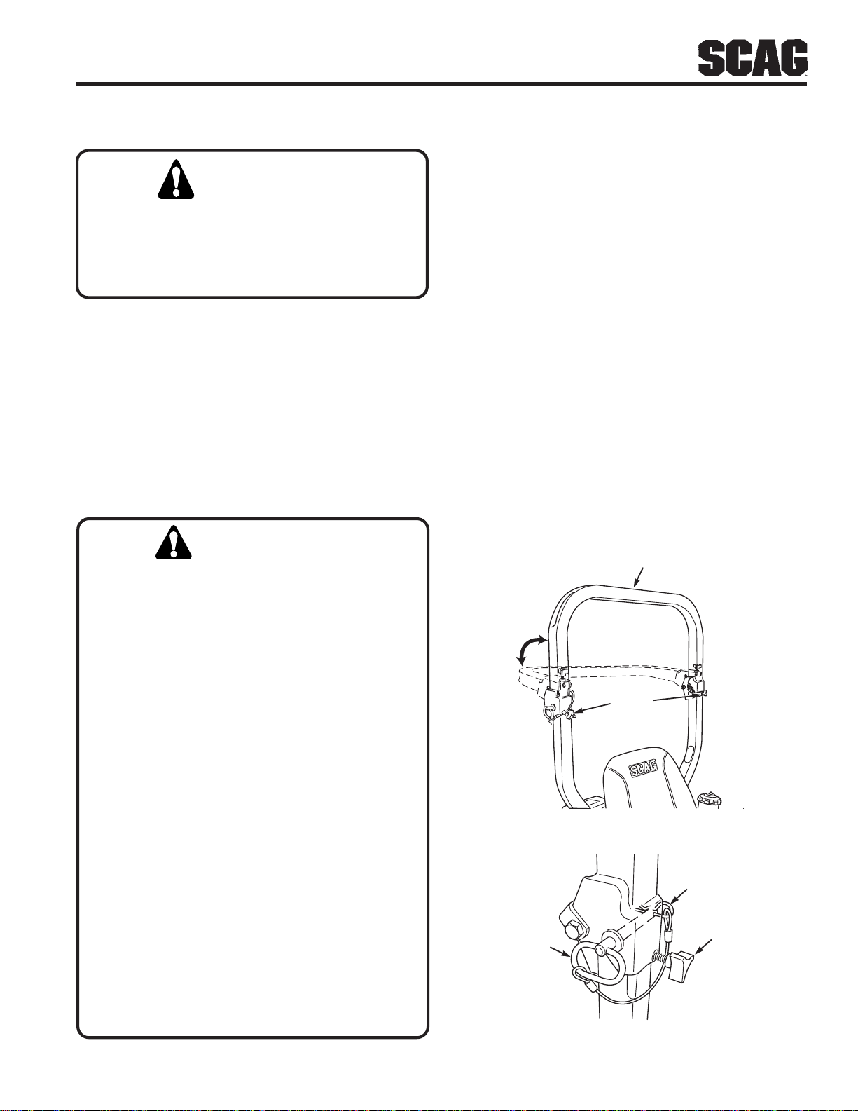
1. T o lower the roll bar, loosen the tension knob on both
the left hand and right hand bar. See Figure 2-1.
2. Remove the hairpin cotter pins and remove the (2) two
lock pins. See Figure 2-2.
3. Lower the roll bar to the down position.
4. Attach the seat belt to the retainer brackets as shown
in Figure 2-3, page 8. The seat belt should only be
attached to the retainer brackets when the roll bar is in
the down position.
5. T o raise the roll bar , lift the bar to the upright position.
6. Install the two (2) lock pins through the hole, secure
with the two (2) hairpin cotter pins and tighten the
tension knobs. See Figure 2-2. Remove the seat belt
from the retainer brackets.
UPRIGHT AND
LOCKED POSITION
There is no roll-over protection when the roll bar is
in the down position.
Lower the roll bar only when absolutely
necessary.
DO NOT wear the seat belt when the roll bar is
in the down position.
ALWAYS wear seat belt when roll bar is in the
up position.
Operate the machine smoothly, no sudden turns,
starts or stops.
Raise the roll bar as soon as clearance permits.
Check the area carefully before mowing for proper
overhead clearance (i.e. branches, doorways, etc.).
TENSION
KNOBS
Figure 2-1 Foldable Roll-Over Protection System
HAIR PIN
TENSION
LOCK PIN
KNOB
DO NOT contact any overhead object with the roll
bar.
Figure 2-2 ROPS Hinge
7
Page 12
Section 2
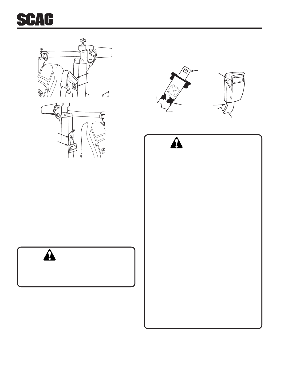
3. Check the buckle and latch for proper operation and
determine if the latch plate is excessively worn,
deformed, or if the buckle is damaged or cracked. See
Figure 2-4.
SEAT BELT
RETAINER
BRACKET
RETAINER
BRACKET
SEAT BELT
Figure 2-3 Seat Belt Retainer Brackets
The potential exposure of the seat belt to severe
enviromental conditions make it crucial to inspect the seat
belt system regularly .
It is recommended that the seat belt be inspected on a
daily basis for signs of damage. Any seat belt system that
shows cuts, fraying, extreme or unusual wear, significant
discoloration due to UV exposure, dirt or stiffness, abrasion
to the seat belt webbing, or damage to the buckle, latch
plate, hardware or any other obvious problem should be
replaced immediately.
WARNING:
INSPECT BUCKLE
& LATCH
INSPECT WEBBING
Figure 2-4 Seat Belt Inspection
WARNING:
Reduce speed when turning, operating on slopes,
slick or wet surfaces. Allow extra distance to stop.
Stay off of slopes too steep for safe operation. To
check a slope, attempt to back up it (with the cutter
deck down). If the machine can not back up the
slope without the wheels slipping, do not operate
the machine on this slope.
ALWAYS travel up or down the slope whenever
possible. Never across the slope.
DO NOT mow near drop-offs, ditches or
embankments. The machine could suddenly roll
over if a wheel goes over the edge or if the edge
caves in.
Failure to properly inspect and maintain the
seat belt can cause serious injury or loss of
life.
1. Check the full length of the seat belt webbing for cuts,
wear, fraying, dirt and stiffness. See Figure 2-4.
2. Check the seat belt webbing in areas exposed to ultra
violet rays from the sun or extreme dust or dirt. If the
original color of the webbing in these areas is extremely
faded and/or is packed with dirt, the physical strength
of this webbing may have deteriorated. If this condition
exists, replace the seat belt system.
Operate the machine smoothly, no sudden turns,
starts or stops on a slope.
NEVER tow on slopes. The weight of the towed
equipment may cause loss of traction and loss of
control.
DO NOT permit untrained personnel to operate
the machine.
8
Page 13
Section 2
2.6 MAINTENANCE CONSIDERATIONS &
STORAGE
1. Never make adjustments to the machine with the
engine running unless specifically instructed to do so.
If the engine is running, keep hands, feet, and
clothing away from moving parts.
2. Disengage drives, lower implement, set parking
brake, stop engine and remove key or disconnect
spark plug wire to prevent accidental starting of the
engine when servicing or adjusting the machine.
W ait for all movement to stop before adjusting,
cleaning or repairing.
3. Disconnect battery or remove spark plug wire before
making any repairs. Disconnect the negative
terminal first and the positive last. Reconnect the
positive first and the negative last.
4. Keep all nuts, bolts and screws tight, to ensure the
machine is in safe working condition. Check blade
mounting bolts frequently to be sure they are tight.
11. Use jack stands to support components when
required.
12. Carefully release pressure from components with
stored energy.
WARNING:
Hydraulic fluid is under high pressure. Keep
body and hands away from pinholes or nozzles
that eject hydraulic fluid under high pressure.
If you need service on your hydraulic system,
please see your authorized Scag dealer. If
hydraulic fluid is injected into the skin, it must
be surgically removed within a few hours by a
doctor or gangrene may result.
13. Let the engine cool before storing.
14. DO NOT store the machine near an open flame.
15. Shut off fuel while storing or transporting.
5. Do not change the engine governor settings or
overspeed the engine. See the engine operator's
manual for information on engine settings.
6. T o reduce fire hazard, keep the cutting units, drives
muffler and engine free of grass, leaves, excessive
grease, oil and dirt.
7. Park the machine on level ground and engage the
parking brake.
8. NEVER allow untrained personnel to service the
machine.
9. Use care when checking blades. Wrap the blade(s)
or wear gloves and use caution when servicing
blades. Only replace blades. NEVER straighten or
weld blades.
10. Keep all parts in good working condition. Replace all
worn or damaged decals.
16. DO NOT store fuel near flames or drain indoors.
17. Charge batteries in an open well ventilated area,
away from spark and flames. Unplug charger before
connecting or disconnecting from battery . Wear
protective clothing and use insulated tools.
9
Page 14
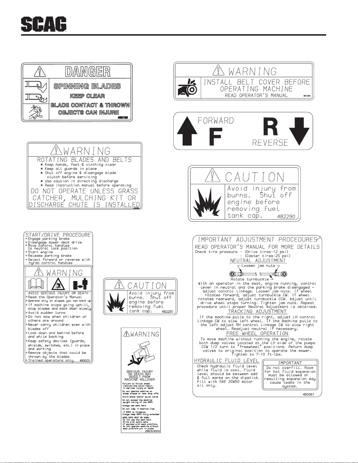
2.7 SAFETY AND INSTRUCTIONAL DECALS
483206
Section 2
481039
482100
483023
482286
482290
482291
10
483061
2006 SZC Safety Decals
Page 15

Section 3
SPECIFICATIONS
3.1 ENGINE
General T ype .............................................................................. Heavy Duty Industrial/Commercial Gasoline
Brand ......................................................................................... Kawasaki, Honda, Briggs & Stratton
Horsepower................................................................................ 16HP (Spec. #) (Scag Model SZC36A-16HN)
17HP (Spec.#) (Scag Model SZC36A-17KAI)
19HP (Spec. #) (Scag Model SZC36A-19KAI, SZC42A-19KAI)
T ype 4-Cycle Gasoline, T win Cylinder, V ertical Shaft
Cylinders.................................................................................... 2 with Cast-Iron Sleeves
Governor .................................................................................... Mechanical Type with V ariable Speed Control Set At 3600 RPM
Idle Speed .................................................................................. 1550 RPM - Kawasaki
Fuel Pump Group ....................................................................... Pulse Fuel Pump with In-Line Fuel Filter, Fixed Jet Carburetor.
Fuel ............................................................................................ Non-Leaded Gasoline with a Minimum Octane Rating of 87
Oil Pump Group .......................................................................... Positive Displacement Gerotor™ Oil Pump
Starter......................................................................................... Electric Starting with Solenoid Shift Starter
Belts: .......................................................................................... Kevlar cord. Self-adjusting, Self-tightening
Pump Drive Belt ......................................................................... Scag Part Number - 483000
3.2 ELECTRICAL
Battery ....................................................................................... 12 V ol t
Charging System........................................................................ Alternator
Charging Output ........................................................................ 12 Volt, 13 Amp - Kawasaki
System Polarity .......................................................................... Negative Ground
Starter......................................................................................... 12 V olt Electric Ring Gear T ype, Key and Solenoid Operated Interlock
Switches..................................................................................... Seat, Neutral Control, Mower Engagement (BBC), Parking Brake
Instrument Panel ........................................................................ Key Switch, Throttle Lever, Manual Choke, PTO Switch
Fuses ......................................................................................... Two (2) 20 Amp
3.3 TRACT OR
Drive System.............................................................................. Hydraulic Drive with Two Variable Displacement Pumps and T wo
Cast-iron High Torque Motors
Hydrostatic Pumps .................................................................... Two Hydro-Gear™ BDP 10A Pumps with Dump V alves for
movement without running the engine
Drive Wheel Motors .................................................................. Two Hydro-Gear™ Cast-Iron High T orque Motors
Steering/Travel Control.............................................................. Twin Lever Fingertip Steering Control with Individual Control to
Each Wheel with Gas Spring Dampers
Parking Brake ............................................................................. Lever Actuated Linkage to Brakes on Both Drive Wheel Axles
Wheels:
(2) Front Caster...................................................................... 11 X 4-5 Four-Ply w/tapered roller bearing pivots
(2) Drive - (48"-52" Deck) ...................................................... 23 X 8.50 X 12 (SZC36A) 23 X 9.50 X 12 (SZC42A)
................................................................................................... Four-Ply Pneumatic Tubeless, Radius Edge
Fuel Tanks.................................................................................. Dual 2.5-Gallon Seamless Polyethylene T anks with large opening ,
Fuel Cap and molded in cup holder
Tire Pressure:
Front Caster........................................................................... Flat Free
Drive ...................................................................................... 12 PS I
Seat ............................................................................................ Molded, Cushioned
11
Page 16

Section 3
3.3 TRACT OR (CONT'D)
Travel Speed:
Forward ................................................................................. 0-7.5 MPH
Reverse.................................................................................. 0-5 MPH
3.4 CUTTER DECK
Type:.......................................................................................... Floating, Adjustable, Anti-scalping, Hybrid Design Combines
Out-front and Belly-mount Designs
Construction: ............................................................................. Dual-plate deck construction, top of deck consists of two steel
................................................................................................... plates 10-gauge and 7 gauge, 7-gauge (3/16") deck skirt.
True Cutting Width:................................................................... 36" (91.44 cm), 42" (106.68 cm)
Cutting Height Adjustment: ....................................................... Foot Operated Lever Adjustment from Operator's Seat, 1.50" to
5.5" in 1/4"increments
Cutter Blades:............................................................................. 197 Thick, Milled Edge, Wear Resistant Marbain™
Blade Engagement: ................................................................... Electric Blade Engagement Clutch with Control Panel Switch
Connected to the Cutter Deck through a Belt.
Discharge Opening: ................................................................... Extra Wide Discharge Opening with Spring Loaded Discharge
Chute and Turbo Baffle
Spindles: .................................................................................... Heavy-duty 1-1/8" Top Dimension Spindle Shaft, Cast Housing,
Taper Roller Bearing, Low Maintenance with Top Access Grease
Fitting and Grease Overfill Relief Poppet
Spindle Pulleys:.......................................................................... Cast Iron (SZC36A), Split Steel (SZC42A) with Easily Removed
................................................................................................... Taper Hubs
Cutter Deck Belts: ...................................................................... B-section with Kevlar Cord. Self-adjusting, self-tightening
SMZC36 ................................................................................ Scag Part Numbers - 483001
SMZC42 ................................................................................ Scag Part Numbers - 483002
Electric Clutch T ype ................................................................... Ogura Heavy Duty PTO Clutch Brake
-NOTE-
The machine will travel at 7.5 mph for
transport purposes. For best cutting
performance the forward travel speed
should be adjusted depending upon the
cutting conditions.
3.6 HYDRAULIC SYSTEM
Hydraulic Oil Filter ..................................................................... 10 Micron Spin-on Element T ype
Hydraulic Reservoir ................................................................... Cast Aluminum; 2 Quart Capacity
3.7 PRODUCTIVITY
The following chart will aid you in determining how many acres your Scag mower will cut per day .
The chart is an estimate based on 8 hours per day cutting time at 6 MPH with a 20% allowance for overlap and turns.
Cutting Width: 36" 42"
Acres Per Day: 14 16
12
Page 17
Section 4
OFF
ON
START
FAST
SLOW
OPERATING INSTRUCTIONS
CAUTION:
Do not attempt to operate this mower unless you
have read this manual. Learn the location and
purpose of all controls and instruments before you
operate this mower .
4.1 CONTROLS AND INSTRUMENT
IDENTIFICATION
Before operating the mower, familiarize yourself with
all mower and engine controls. Knowing the location,
function and operation of these controls is important for
safe and efficient operation of the mower.
1 . Ignition Switch (Figure 4-1). Used to start the
engine and has three positions; OFF, ON, and
START.
2 . Mower Deck Switch (Figure 4-1). Used to
engage and disengage the mower drive system.
Pulling up on the switch will engage the deck drive.
Pushing down on the switch will disengage the deck
drive.
3 . Engine Choke Control (Figure 4-1). Used to
start a cold engine.
4 . Engine Throttle Control (Figure 4-1). Used to
control the engine speed. Pushing the lever forward
increases engine speed. Pulling the lever back
decreases engine speed. Full backward position is
the IDLE position. Full forward is the cutting
position.
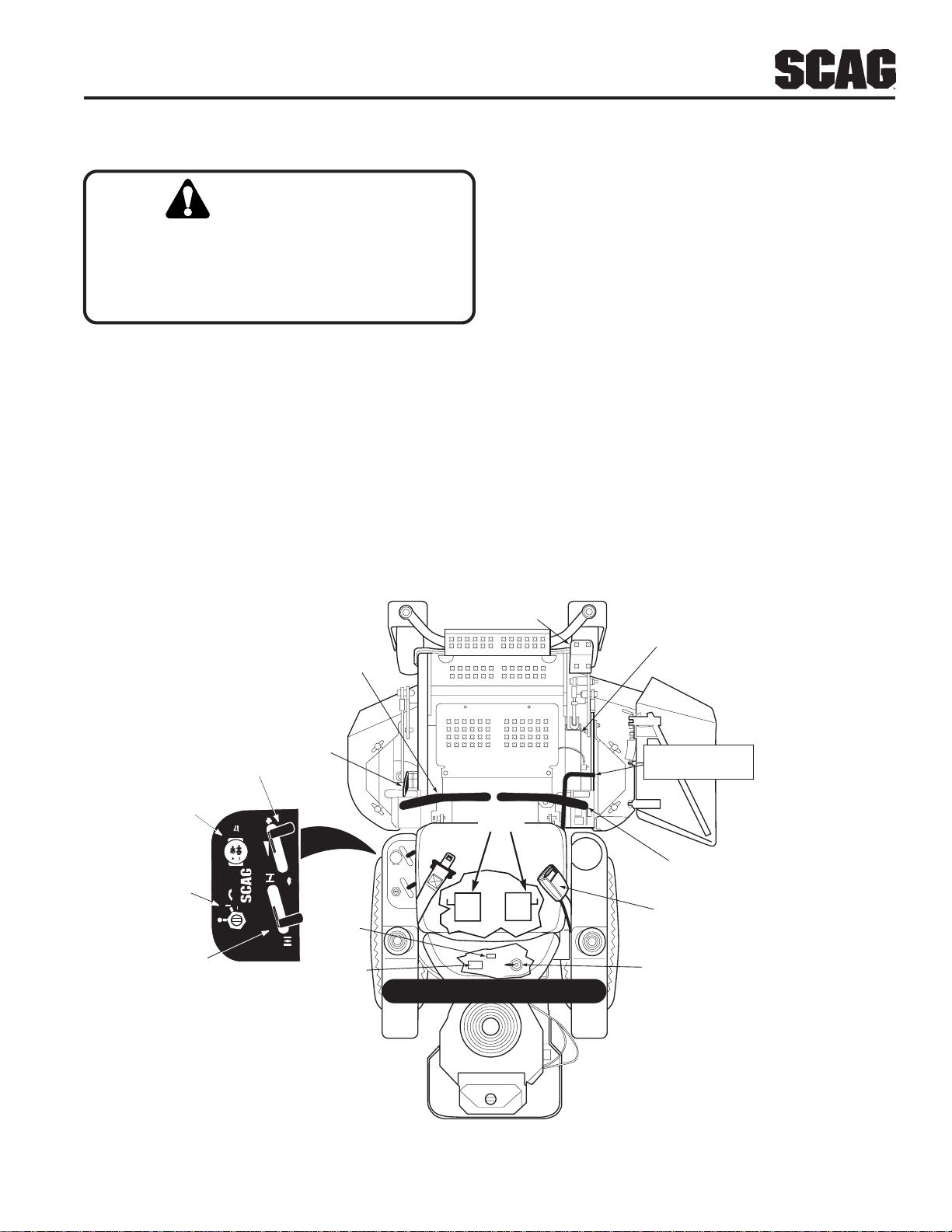
ENGINE THROTTLE CONTROL
MOWER
DECK
SWITCH
IGNITION
SWITCH
ENGINE
CHOKE
CONTROL
DECK LIFT
LEFT STEERING
CONTROL
PARKING
BRAKE
FAST
DISENGAGE
PUSH IN TO
TO ENGAGE
PULL OUT
MOWER DECK
SLOW
START
POWER EQUIPMENT
ON
OFF
CHOKE
FUSES
HOUR
METER
DUMP
VALV E
CUTTING HEIGHT
ADJUSTMENT
CUTTER DECK
RELEASE LEVER
RIGHT STEERING
CONTROL
SEAT BELT
FUEL SWITCHING
VALV E
SZC 2005 CAI
Figure 4-1 Controls and Instruments
13
Page 18
Section 4
5 . Hourmeter (Figure 4-1). Indicates the number of
hours the engine has been operated. It operates
whenever the ignition key switch is in the ON
position. Has preset maintenance reminders for
engine and hydraulic system oil changes. Will start
flashing scheduled maintenance 2 hours before
preset time and continue flashing until 2 hours after.
Automatically resets.
6 . Fuse Holders (Figure 4-1). Two 20-amp fuses
protect the mower’s electrical system. To replace
fuses, pull fuse out of the socket and install a new
fuse.
7 . Left Steering Control (Figure 4-1). Used to
control the mower's left wheel when traveling
forward or reverse.
8 . Right Steering Control (Figure 4-1). Used to
control the mower's right wheel when traveling
forward or reverse.
DUMP VALVE
CONTROL
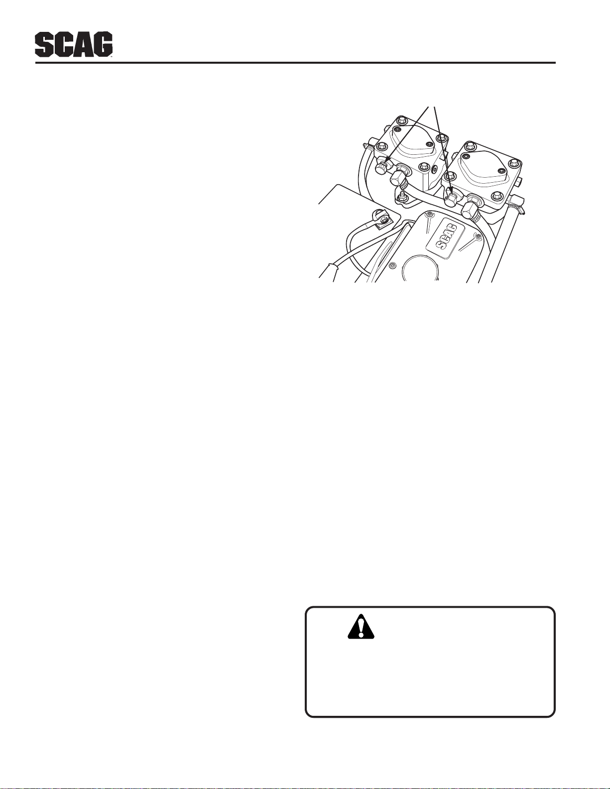
Figure 4-2 Dump Valve Control
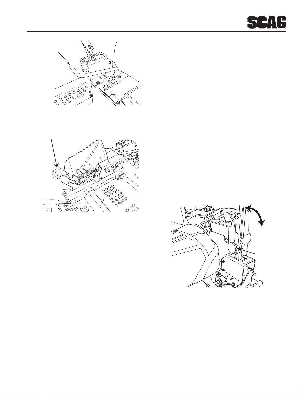
14. Cutter Deck Release Lever (Figure 4-1). Used
to lock the cutter deck in the transport position. Push
the foot pedal forward and lift up on the release lever
to release the cutter deck for normal mowing.
9 . Parking Brake Control (Figure 4-1). Used to
engage and disengage the parking brakes. Pull the
lever back to engage the parking brakes. Push the
lever forward to disengage the parking brakes.
10 . Fuel Switching Valve (Figure 4-1). Located on
the left side of the machine. Used to shut off fuel
supply to the engine and change fuel supply between
the fuel tanks. Rotate the valve counter-clockwise
to supply fuel from the tank on the left side only.
Rotate the valve clockwise to supply fuel from the
tank on the right side only .
11. Dump Valve Control (Figure 4-2). Located on
the hydraulic pumps, used to “free-wheel” the
mower. Rotating the levers clockwise until they stop
allows the unit to move under hydraulic power. The
levers must be in this position and torqued to 10ft/lbs
during operation of the mower. Rotating the levers
counter-clockwise, 1-2 turns, allows the mower to be
moved by hand (free-wheeling).
12. Deck Lift Foot Lever (Figure 4-1). Used to raise
and lower the cutter deck.
15 . Seat Belt (Figure 4-1). Used to secure the
operator. Seat belt must be worn at all times during
operation.
4.2 SAFETY INTERLOCK SYSTEM
The mower is equipped with a safety interlock system
that prevents the engine from starting unless the deck
drive is disengaged, the parking brake is engaged, the
steering control levers are in the neutral position and the
operator is in the seat. The interlock system shuts off
the engine if the operator leaves the seat with the
steering control levers not in the neutral position and/or
the cutter blades engaged and/or the parking brake not
engaged.
WARNING:
Never operate the mower with the interlock
system disconnected or malfunctioning. Do not
disengage or bypass any switch; injury to yourself
and others or property damage could result.
13 . Cutting Height Adjustment (Figure 4-1). Used
to set the cutter deck at the desired cutting height.
14
Page 19
Section 4
4.3 INITIAL RUN-IN PROCEDURES (First
Day of Use or Approximately 10 Hours)
1. Check all belts for proper alignment and wear at 2, 4
and 8 hours.
2. Change the engine oil and oil filter after the first 20
hours of operation. (See Section 7.4.)
3. Check hydraulic oil level in reservoir. (See Section
7.3)
4. Check for loose hardware. Tighten as needed.
5. Check interlock system for proper operation. (See
Section 4.2)
6. Check tire pressure. Adjust pressure if necessary.
(See Section 7.10)
4.4 STARTING THE ENGINE
6. Turn the ignition key to the START position and
release the key as soon as the engine starts. Do not
hold the key in the ST ART position for more than 15
seconds at a time. Allow at least 60 seconds
between each cranking attempt to prevent
overheating of the starter motor. Prolonged cranking
can damage the starter motor and shorten battery
life.
7. Allow engine to warm before operating the mower.
4.5 GROUND TRAVEL AND STEERING
-IMPORTANT-
If you are not familiar with the operation of a
machine with lever steering and/or
hydrostatic transmissions, the steering and
ground speed operations should be learned
and practiced in an open area, away from
buildings, fences, or obstructions. Practice
until you are comfortable with the handling of
the machine before attempting to mow. Learn
the operation on flat ground before operating
on slopes.
CAUTION:
DO NOT USE STARTING FLUIDS. Use of starting
fluids in the air intake system may be potentially
explosive or cause a “runaway” engine condition
that could result in engine damage and/or personal
injury.
1. Be sure the fuel shutoff valve, located behind the
operator's seat by the left fuel tank, is completely
open. (See Section 7.5)
2. Sit in the operator’s seat, fasten seat belt and place
the steering control levers in the neutral position.
3. Engage the parking brake.
4. If the engine is cold, choke the engine as needed.
5. Move the engine throttle control to about half engine
speed.
-IMPORTANT-
Start practicing with a slow engine speed and
slow forward travel. Learn to feather the
steering controls to obtain a smooth
operating action.
Forward T ravel
T o travel forward with the mower, disengage the parking
brake, pull levers inward out of the neutral lock position
and slowly push the steering control levers forward an
equal distance. The further the steering control levers
are pushed forward the greater the forward speed will
be. To increase the speed, push the steering control
levers further forward and to decrease the speed, pull the
steering control levers back.
T o stop the forward travel, pull the steering control levers
back to the neutral position.
T o steer the mower left while traveling forward, pull the
left steering lever back. The further the lever is pulled
back, the quicker the mower will turn left.
15
Page 20
Section 4
T o steer the mower right while traveling forward, pull the
right steering control lever back. The further the lever is
pulled back, the quicker the mower will turn right.
-NOTE-
Smooth operation of the steering levers will
produce smooth mower operation. While
learning the operation of the steering
controls, keep the travel speed low.
-IMPORTANT-
Do not travel forward over a curb. The
mower may hang up on the curb. Raise the
deck and travel backwards over the curb at a
45 degree angle. (see section 4.1, item 12 for
cutter deck raising instructions)
Reverse Travel
CAUTION:
Disengage power to the mower before backing up.
Do not mow in reverse unless absolutely necessary
and then only after observation of the entire area
behind the mower .
CAUTION:
T o steer right while traveling in reverse, allow the right
steering control lever to move forward. The further the
control is allowed to move forward, the quicker the
mower will turn right.
T o stop the reverse travel, allow the steering control
levers to return to the neutral position. If the mower is to
be parked, place the handles in the neutral lock position
and engage the parking brake.
4.6 ENGAGING THE DECK DRIVE (CUTTER
BLADES)
1. Set the throttle at about 3/4 speed. Do not attempt to
engage the deck drive at high speed as this shortens
the electric clutch life — use only moderate engine
speed when engaging the deck drive.
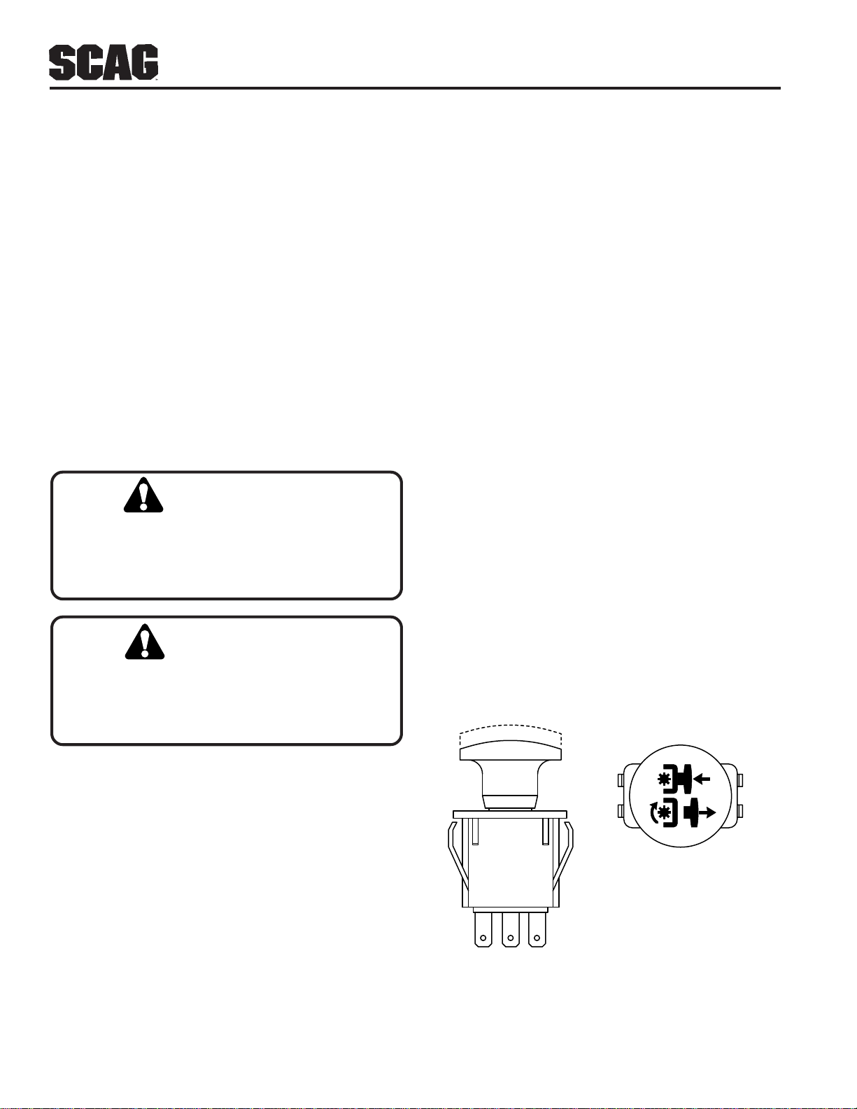
2. Engage the deck drive by pulling out on the yellow
switch, located on the instrument panel, (Figure 4-3)
to the engage position.
-NOTE-
A squealing noise may be heard when
engaging or disengaging the deck drive. It is
caused by the electric clutch plates meshing
as the mower comes up to speed. This is
normal.
Before backing up, obser ve the rear for persons
and obstructions. Clear the area before backing
up. P ossible injury or property damage could occur.
T o travel in reverse, pull levers inward out of the neutral
lock position and pull both handles back. Keep the travel
speed low while traveling in reverse.
-NOTE-
The mower may not travel straight in reverse.
Slight adjustments must be made using the
steering controls.
T o steer left while traveling in reverse, allow the left
steering control lever to move forward. The further the
control is allowed to move forward, the quicker the
mower will turn left.
PULL UP TO ENGAGE
PUSH DOWN TO DISENGAGE
STT99CES
Figure 4-3 Cutter Deck Engage Switch
16
Page 21
Section 4
3. T o disengage the deck drive, push the switch in to
the disengage position.
4. Always operate the engine at full throttle to properly
maintain cutting speed. If the engine starts to lug
down, reduce the forward speed and allow the
engine to operate at maximum RPM.
4.7 HILLSIDE OPERATION
WARNING:
DO NOT operate on steep slopes. T o check a slope,
attempt to back up it (with the cutter deck down). If
the machine can back up the slope without the
wheels slipping, reduce speed and use extreme
caution. ALWAYS FOLLOW OSHA APPROVED
OPERATION.
1. The mower has been designed for good traction and
stability under normal mowing conditions. However,
caution must be used when traveling on slopes,
especially when the grass is wet. Wet grass reduces
traction and steering control. The Roll-Over
Protection System is standard equipment for this
machine. See section 2.5, page 7 of this manual for
further details.
2. T o prevent tipping or loss of control, do not start or
stop suddenly, avoid unnecessary turns and travel at
reduced speed. If tires lose traction, disengage
blades and proceed slowly off the slope.
4.8 PARKING THE MOWER
1. Park the machine on a flat, level surface only. Do not
park the machine on an incline.
2. Place the steering control levers in the neutral
position.
3. Disengage the cutter blades.
4. Slow the engine to idle speed.
5. Engage the parking brake.
6. Turn the ignition key to the OFF position and remove
the key.
4.9 AFTER OPERA TION
1. Wash the entire mower after each use. Do not use
high pressure spray or direct the spray onto
electrical components.
-IMPORTANT-
Do not wash a hot or running engine. Cold
water will damage the engine. Use compressed
air to clean the engine if it is hot.
2. Keep the entire mower clean to inhibit serious heat
damage to the engine or hydraulic oil circuit.
3. Check the drive belts for proper alignment and any
signs of wear. Correct and adjust if necessary.
3. A void sudden starts when mowing uphill. Sudden
starts may cause the machine to tip backwards.
4. Loss of traction may occur when traveling down hill.
Weight transfers to the front of the machine and may
cause the drive wheels to slip causing loss of braking
or steering.
5. Keep tires properly inflated.
T o avoid injury from b urns, allo w the mower to cool
before removing the fuel tank cap and refueling.
4. After the mower has cooled down, fill the fuel tanks
with fresh, clean fuel at the end of every day of
operation. See Engine Owner's Manual for proper
octane requirements.
5. Check the tire pressure. Adjust pressure if necessary.
17
Page 22
Section 4
WARNING
4.10 REMOVING CLOGGED MATERIAL
ROTATING BLADES
NEVER PUT Y OUR HANDS INT O THE DISCHARGE
CHUTE FOR ANY REASON! Shut off the engine and
remove the key and only then use a stick or similar
object to remove material if clogging has occurred.
1. If the discharge chute becomes clogged, shut off the
engine and remove the ignition key . Using a stick or
similar item, dislodge the clogged material. Then
resume normal mowing.
4.11 MOVING MOWER WITH ENGINE
STOPPED
To “free-wheel” or move the mower around without the
engine running, place the dump valve levers in the FREEWHEEL position (Figure 4-2, page 14). Disengage the
parking brake and move the mower by hand. The dump
valve levers must be returned to the DRIVE position and
torqued to 7-10 ft/lbs to drive the mower.
4. Keep mower and discharge chute clean.
5. When mowing wet or tall grass, mow the grass
twice. Raise the mower to the highest setting for the
first pass and then make a second pass to the desired
height.
6. Use a slow travel speed for trimming purposes.
7. Operate the engine at full throttle for best cutting.
Mowing with a lower RPM causes the mower to
tear the grass. The engine is designed to be
operated at full speed.
8. Use the alternate stripe pattern for best lawn
appearance. Vary the direction of the stripe each
time the grass is mowed to avoid wear patterns in
the grass.
4.13 ADJUSTING CUTTING HEIGHT
The mower deck can be adjusted from a height of 1-1/2
inch to 5-1/2 inches at 1/4-inch intervals. T o adjust the
cutting height:
4.12 RECOMMENDATIONS FOR MO WING
1. Do not mow with dull blades. A dull blade will tear
grass, resulting in poor lawn appearance and require
extra power.
2. The discharge chute must not be removed and must
be kept in the lowest position to deflect grass
clippings and thrown objects downward. Direct the
side discharge away from sidewalks or streets to
minimize cleanup of clippings. When mowing close
to obstacles, direct the discharge away from the
obstacles to reduce the chance of property damage
by thrown objects.
WARNING
DO NOT OPERATE WITHOUT DISCHARGE CHUTE, MULCHING
KIT, OR ENTIRE GRASS CATCHER INSTALLED
3. Cut grass when it is dry and not too tall. Do not cut
grass too short (cut off 1/3 or less of existing grass
for best appearance). Mow frequently.
WARNING:
DO NOT adjust the cutting height with the mower
blades rotating. Disengage the power to the cutter
blades and then adjust cutting height.
1. Disengage the power to the cutter blades.
2. Push the cutting height adjustment foot pedal all the
way forward using your right foot until it locks in
place. (Figure 4-5, page 19).
3. Insert the lanyard pin into the cutting height index at
the desired cutting height. Push forward on the deck
lift foot lever, hold in place and lift up on the deck
release lever, (Figure 4-4). Slowly release the foot
pedal. A deck height decal is located on the cutting
height index as an aid in adjusting the deck to the
desired height. (Figure 4-5).
18
Page 23
Section 4
DECK RELEASE
LEVER
Figure 4-4 Deck Release Lever
HEIGHT ADJUSTMENT
PEDAL
4.14 Adjusting the Steering Levers
1. Position the seat to the desired location.
2. While in the operator's position with out the engine
running, move both steering levers forward and
reverse to check for full function control and
comfort.
3. If adjustment of the steering levers is needed, use the
following instructions to adjust.
A. Loosen the tension knob on the lever assembly .
B. Rotate the steering lever forward or backward to
achieve the optimum operating position.
C. Tighten the tension knob and repeat on the
opposite side.
D. While in the operators position, bring the steering
levers out of the neutral lock position and check
to make sure both levers are even before
operating.
Figure 4-5 Adjusting Cutting Height
RO TATE
LEVER
TENSION
KNOB
Figure 4-6 Adjusting Steering Levers
4. The control handle can also be adjusted in two
different positions. If necessary, remove the two
bolts securing the control handle to the control lever.
Install the handle in the desired position.
19
Page 24
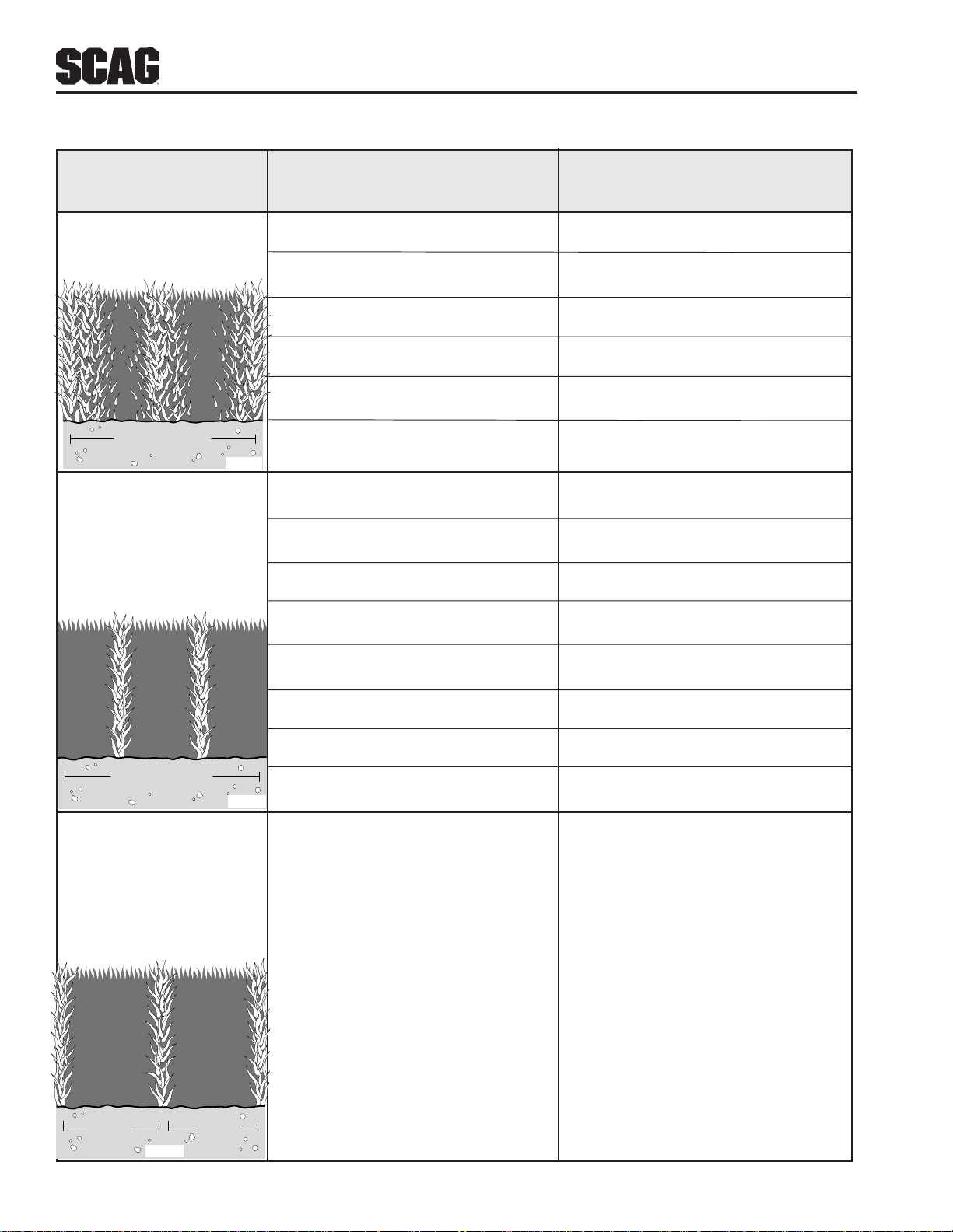
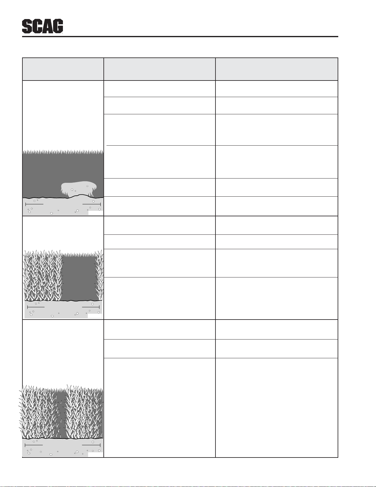
TROUBLESHOOTING CUTTING CONDITIONS
Section 5
CONDITION
CAUSE
CURE
Stringers - Occasional Low engine RPM Run engine at full RPM
Blades of Uncut
Grass Ground speed too fast Slow speed to adjust for conditions
Wet grass Cut grass after it has dried out
Dull blades, incorrect sharpening Sharpen blades
Deck plugged, grass accumulation Clean underside of deck
Width of Deck
SGB020
Belts slipping Adjust belt tension
Streaking - Strips of Dull, worn blades Sharpen blades
Uncut Grass in Cutting
Path Incorrect blade sharpening Sharpen blades
Low engine RPM Run engine at full RPM
Belt slipping Adjust belt tension
Deck plugged, grass accumulation Clean underside of deck
Ground speed too fast Slow speed to adjust for conditions
Wet grass Cut grass after it has dried out
Width of Deck
SGB018
Bent blades Replace blades
Streaking - Strips of Not enough overlapping Increase the overlap of each
Uncut Grass Between between rows pass
Cutting Paths
Width
of
Deck
SGB019
Width
of
Deck
20
Page 25
Section 5
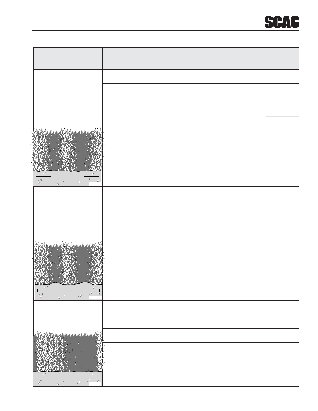
TROUBLESHOOTING (CONT'D)
CONDITION
CAUSE
CURE
Uneven Cut on Flat Lift worn from blade Replace blade
Ground - Wavy
High-Low Blade upside down Mount with cutting edge toward
Appearance, ground
Scalloped Cut, or
Rough Contour Deck plugged, grass accumulation Clean underside of deck
Too much blade angle (deck pitch) Adjust pitch and level
Deck mounted improperly See your authorized SCAG dealer
Bent spindle area See your authorized SCAG dealer
Dull blade Sharpen blade
Width of Deck
SGB020
Uneven Cut on Uneven ground May need to reduce ground speed,
Uneven Ground - raise cutting height, and/or change
Wavy Appearance, direction of cut
High-Low Scalloped
Cut, or Rough Contour
Width of Deck
SGB021
Sloping Ridge Across Tire pressures not equal Check and adjust tire pressure
Width of Cutting Path
Wheels uneven Check and adjust tire pressure
Deck mounted incorrectly See your authorized SCAG dealer
Deck not level side-to side Check for level and correct
Width of Deck
SGB023
21
Page 26
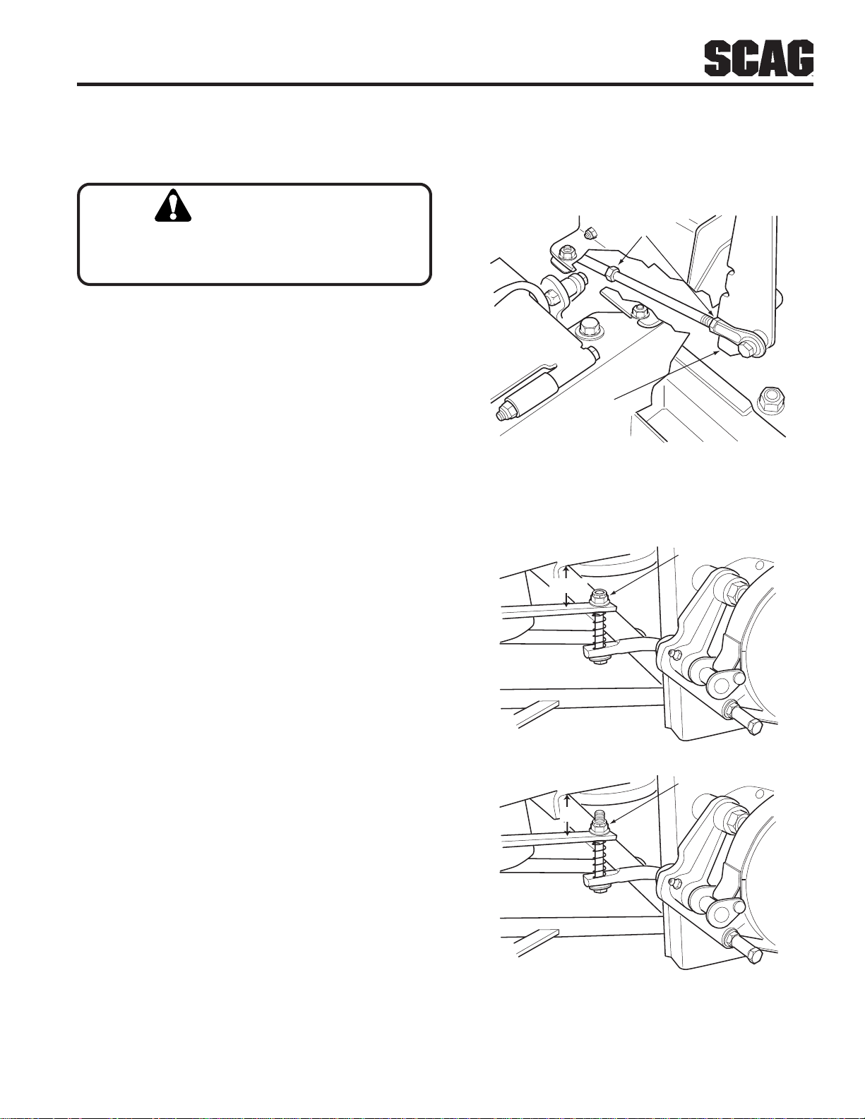
TROUBLESHOOTING (CONT'D)
Section 5
CONDITION
CAUSE
CURE
Scalping - Blades Low tire pressures Check and adjust pressures
Hitting Dirt or
Cutting Very Close to Ground speed too fast Slow speed to adjust for conditions
the Ground
Cutting too low May need to reduce ground speed,
raise cutting height, change direction
of cut, and/or change pitch and level
Rough terrain May need to reduce ground speed,
raise cutting height, and/or change
direction of cut
Ground speed too fast Slow speed to adjust for conditions
Width of Deck
SGB022
Step Cut -Ridge Blades not mounted evenly Adjust pitch and level
in Center of
Cutting path Bent blade Replace blade
Wet grass Cut grass after it has dried out
Internal spindle failure See your authorized SCAG dealer
Mounting of spindle incorrect See your authorized SCAG dealer
Width of Deck
SGB024
Slope Cut - Sloping Bent spindle mounting area See your authorized SCAG dealer
Ridges Across Width
of Cutting Path Internal spindle failure See your authorized SCAG dealer
Bent deck housing See your authorized SCAG dealer
Width of Deck
SGB025
22
Page 27
Section 6
ADJUSTMENTS
6.1 PARKING BRAKE ADJUSTMENT
WARNING:
DO NOT operate the mower if the parking brake is
not operable. Possib le severe injury could result.
The parking brake linkage should be adjusted whenever
the parking brake lever is placed in the “ENGAGE”
position and the parking brake will not prevent the mower
from moving. If the following procedures do not allow
you to engage the parking brake properly , contact your
Scag dealer for further brake adjustments.
1. Position a floor jack under the rear of the machine.
Raise the machine and support it to prevent it from
falling. Block the caster wheels to prevent the
machine from moving. Remove the drive wheels.
-NOTE-
If this procedure does not achieve proper brake
adjustment, please contact your authorized Scag
dealer.
LOOSEN
HERE
BRAKE
HANDLE
SZC 2005 BA
Figure 6-1. Brake Adjustment
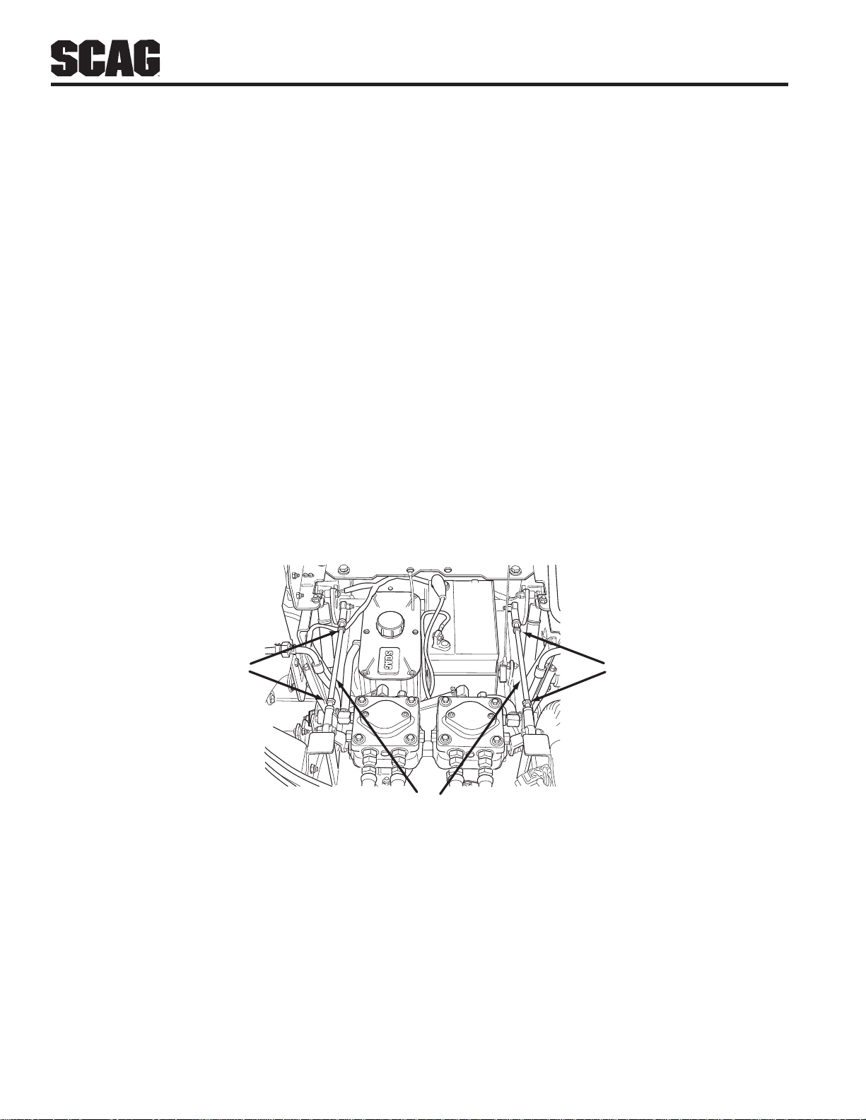
2. Loosen the nut on the top of the actuator bar until it
is flush with the end of the bolt. (See Figure 6-2, top
view).
3. Measure the distance between frame and the top of
the actuator bar. The distance should be 1-1/4". If
this measurement is not at the specified 1-1/4", adjust
the brake control rod. Adjust by loosening the jam
nuts at both ends of the brake control rod and turning
the rod until the proper distance is achieved. Tighten
the jam nuts. (See Figure 6-1).
5. When the 1-1/4" measurement has been acheived,
tighten the nut on the top of the actuator bar until the
measurement between the frame and actuator bar is
approximately 2".
6. Check the measurement on the RH side between the
frame and actuator bar. This measurement should
be approximately 2". If the measurement is not at 2",
tighten or loosen the nut on top of the actuator bar
until the 2" measurement is acheived.
LOOSEN
HERE
1-1/4"
TIGHTEN
HERE
2"
SZC 2005 BRA
7. Replace the drive wheels and test the brake.
Figure 6-2. Brake Rod Adjustment
23
Page 28
Section 6
6.2 TRAVEL ADJUSTMENTS
Neutral or tracking adjustments will need to be made if:
A. The steering control levers are in the neutral
position and the machine creeps forward or
backward. (See Neutral Adjustment).
B. The steering control levers are in the full forward
position and the mower pulls to one side or the
other when traveling in a forward direction.
(Tracking Adjustment, See Page 25).
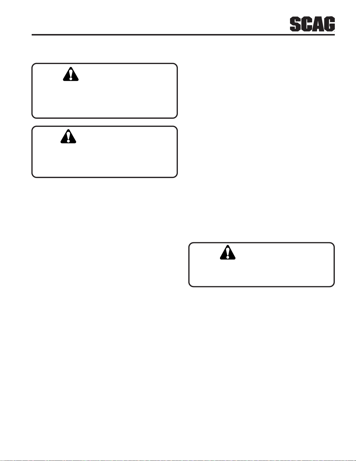
Neutral Adjustment
1. Be sure the dump valve levers are in the run position
and the steering control levers are in the neutral lock
position.
2. With an operator in the seat, start the engine and
disengage the parking brake.
3. Run the engine at full operating speed and check if
the machine creeps forward or backwards.
4. Adjust the RH wheel by loosening the jam nuts on
the steering control rod and turning the rod until the
drive wheel turns in the forward direction. Turn the
rod back until the drive wheel stops moving. Turn
the rod back an additional 1/2 turn. (See Figure 6-3).
5. Tighten the jam nuts and repeat for the LH wheel.
6. Actuate the steering control levers forward and
reverse several times and return them to the neutral
position.
7. Check that the drive wheels remained in neutral and
readjust if necessary.
8. Check that the steering control levers hit the stop
before the pumps reach full stroke. Adjust as
needed.
LEFT STEERING
CONTROL ROD
LOOSEN HERE
RIGHT STEERING
CONTROL ROD
LOOSEN HERE
ADJUST
HERE
Figure 6-3. Steering Control Rods Adjustment
24
Page 29
Section 6
Tracking Adjustment
CAUTION:
Stop the engine and remove the key from the
ignition before making any adjustments. W ait for
all moving parts to come to a complete stop
before beginning work.
CAUTION:
The engine and drive unit can get hot during
operation causing burn injuries. Allow engine
and drive components to cool before making any
adjustments.
-NOTE-
Before proceeding with this adjustment, be sure
that the caster wheels turn freely and that the tire
pressure in the drive wheels is correct. If the tire
pressure is not correct, the machine will pull to
the side with the lower pressure.
A. Stop the machine and place the steering control
levers in the neutral position. Loosen the lock
nuts securing the ball joints at each end of the
RH steering control rod. Rotate the control rod
to shorten the rod and tighten the lock nuts.
This will cause the control rod to stroke the RH
pump less, slowing down the RH wheel. (See
Figure 6-3, page 24).
-NOTE-
If after making the adjustment as outlined in step
2A, the machine creeps forward or backward, the
neutral adjustment must be made as described on
page 24.
6.3 THROTTLE CONTROL AND CHOKE
ADJUSTMENTS
Throttle control and choke adjustments must be
performed by your Scag dealer to ensure proper and
efficient running of the engine. Should either need
adjustment, contact your authorized Scag service center.
6.4 BELT ADJUSTMENT
1. If at full speed the mower pulls right, it is an
indication that the left wheel is turning faster than the
right wheel. T o adjust this condition, proceed as
follows:
A. Stop the machine and place the steering control
levers in the neutral position. Loosen the lock
nuts securing the ball joints at each end of the
LH steering control rod. Rotate the control rod
to shorten the rod and tighten the lock nuts.
This will cause the control rod to stroke the LH
pump less, slowing down the LH wheel. (See
Figure 6-3).
-NOTE-
If after making the adjustment as outlined in step
1A, the machine creeps forward or backward, the
neutral adjustment must be made as described on
page 24.
2. If at full speed the mower pulls left, it is an indication
that the right wheel is turning faster than the left
wheel. T o adjust this condition, proceed as follows:
WARNING:
Before removing any guards, shut the
engine off and remove the ignition key.
All drive belts and cutter deck belts are spring-loaded
and self-tensioning. The belts should be checked
periodically for proper alignment and wear.
6.5 BELT ALIGNMENT
Belt alignment is important for proper performance of
your Scag mower. If you experience frequent belt wear
or breakage, see your authorized Scag service center for
belt adjustment.
25
Page 30
Section 6
6.6 CUTTER DECK ADJUSTMENTS
Cutter deck level, pitch and height are set at the factory.
However, if these adjustments should ever need to be
made, the following procedures will aid in obtaining the
proper cutter deck adjustment.
-NOTE-
Before proceeding with the cutter deck
adjustments, be sure that all tires are properly
inflated.
Cutter Deck Level
The cutter deck should be level from side-to-side for
proper cutting performance. To check for level, be sure
that the mower is on a flat, level surface, the tires are
properly inflated and the cutter deck is set at the most
common cutting height that you will use. On the RH side
of the machine, check the distance from the top of the
cutter deck to the floor. Next check the distance from
the top of the cutter deck to the floor on the LH side of
the machine. Both measurements should be the same.
If the two measurements are different, the cutter deck
level must be adjusted as follows:
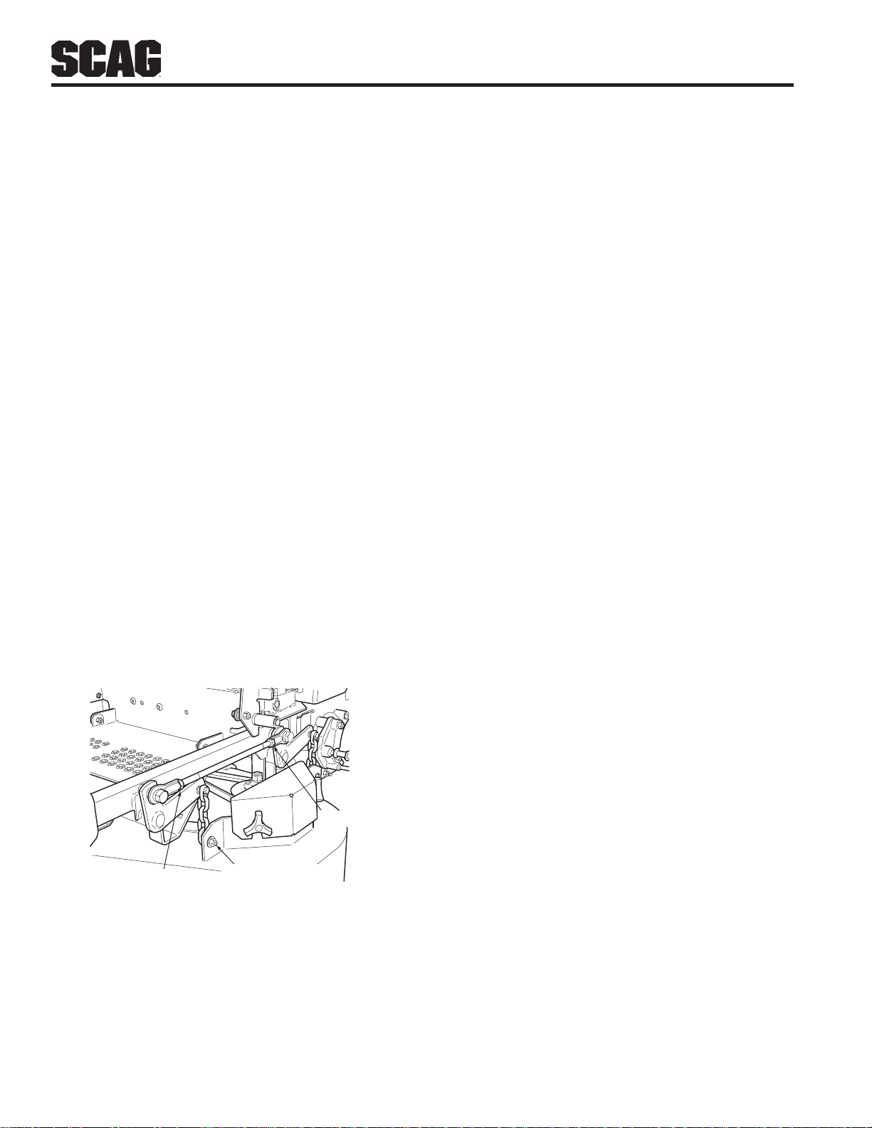
1. On the front LH side of the cutter deck locate the
cutter deck adjusting bolt. (See Figure 6-4)
2. Loosen the elastic stop nut and move the bolt up or
down in the slot to adjust the cutter deck until the
distance from the top of the cutter deck to the floor
is the same as the measurement on the RH side of
the machine.
3. Tighten the elastic stop nut to secure the cutter deck
in the proper position.
Cutter Deck Pitch
The pitch of the cutter deck should be equal between the
front and rear of the cutter deck for proper cutting
performance. To check for proper deck pitch, be sure
that the mower is on a flat, level surface and the tires are
properly inflated.
Check the distance from the top of the cutter deck to the
floor at the rear RH side of the cutter deck directly
behind the cutter deck hanging chains. Next check the
distance from the top of the cutter deck to the floor at
the front RH side of the cutter deck directly in front of
the cutter deck hanging chains. The measurement at the
front of the cutter deck should be the same as the rear of
the deck. Make these measurements at the LH side of
the cutter deck also. If the measurement at the front of
the deck is not the same, the cutter deck pitch must be
adjusted as follows:
LOCK NUT
LOCK NUT
CUTTER DECK
ADJUSTING BOLT
Figure 6-4. Cutter Deck Adjustment
1. Loosen the lock nuts on both adjusting rods.
(See Figure 6-4)
2. Using an adjustable jaw pliers, turn the adjusting rods
on the non-threaded portion of the rod until the deck
is equal front to back on both the RH and the LH
side of the cutter deck. Tighten both lock nuts.
-NOTE-
To prevent the cutter deck from teetering, all four
cutter deck hanging chains must have tension on
them. If all four chains do not have tension on
them and the deck teeters, you must readjust the
cutter deck as outlined in the procedures above.
All measurements should be taken from the top
edge of the deck as the Advantage decks have an
uneven bottom edge.
26
Page 31
Section 6
Cutter Deck Height
The cutter deck height adjustment is made to ensure that
the cutter deck is cutting at the height indicated on the
cutting height index gauge. To check for proper deck
height, be sure that the mower is on a flat, level surface
and the tires are properly inflated.
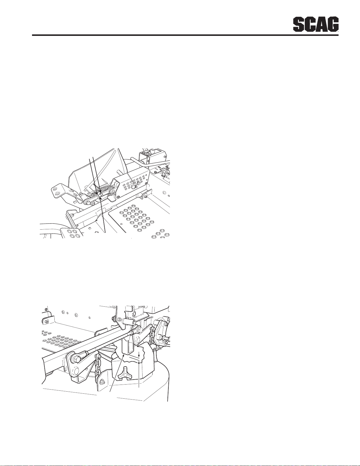
1. Place the cutter deck in the transport position.
Loosen the jam nuts on both ends of the deck height
control rod. (See Figure 6-5)
LOOSEN
HERE
CONTROL ROD
3. Check the cutter deck cutting height by placing the
lanyard pin in the 3" position on the cutting height
index. Release the deck from the transport positon
and allow the deck to move to the 3" cutting height
position.
4. Check the measurement from the floor to the cutter
blade tip. If the measurement is not at 3", an
adjustment can be made using the deck height
control rod. (See Figure 6-5)
-NOTE-
If an adjustment had to be made, be sure that the
cutter deck can easily be locked into the
transport position.
Custom-Cut Baffle Adjustment
The Custom-Cut Baffle is designed to deliver optimum
airflow and superior cutting performance in any type of
grass. The Custom-Cut Baffle can be raised or lowered
to precisely tailor the deck's performance for the type of
grass being cut. The baffle can be set in three (3)
different positions for optimum performance.
Figure 6-5. Cutter Deck Height Adjustment
2. Turn the control rod (See Figure 6-6) until there is a
1/4" space between the rear deck stop and the top of
the cutter deck. (See Figure 6-6). Tighten the jam
nuts on the control rod.
DECK
STOP
1/4"
SZC 2005 CDS
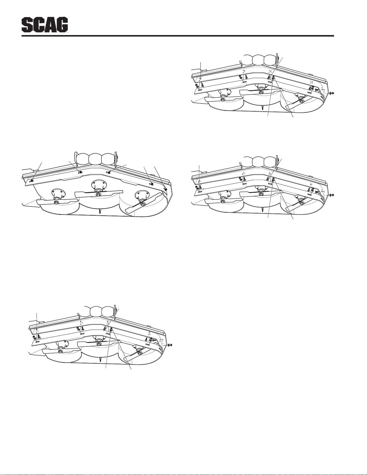
A. 3" Position - baffle is installed using the top set of
holes on the front baffle welded inside the cutter
deck. (See Figure 6.8). The Advantage cutter deck
will deliver the best quality-of-cut in very tall, wiry ,
tough to cut grass.
B. 3-1/2" Position (factory setting) - baffle is installed
using the middle set of holes on the front baffle
welded inside the cutter deck. (See Figure 6.9). For
general purpose cutting, place the Custom-Cut Baffle
in the 3-1/2" position. This gives the best mix of
cutting performance in all types of grass.
C. 4" Position - baffle is installed using the bottom set of
holes on the front baffle welded inside the cutter
deck. (See Figure 6.10). Placing the baffle in the 4"
setting will enhance fall cutting (leaf pickup) and
reduce cutter deck "blowout".
Figure 6-6. Cutter Deck Stop
27
Page 32
Section 6
T o adjust the Custom-Cut Baffle height:
1. Place the cutter deck in the transport position.
2. Remove the hardware securing the Custom-Cut
Baffle to the cutter deck. (See Figure 6.7).
-NOTE-
Hardware location used in the illustrations are
for reference only. Location of hardware may
vary depending on cutter deck size.
MOUNTING
HARDWARE
MOUNTING
HARDWARE
Figure 6-7. Custom-Cut Baffle
2004 CCB
MIDDLE SET OF HOLES
FOR 3-1/2" SETTING
FLATWASHER
CARRIAGE BOLT
2004 CCB - 3-1/2" Setting
ELASTIC STOP
NUT
Figure 6-9. 3-1/2" Custom-Cut Baffle Position
BOTTOM SET OF HOLES
FOR 4" SETTING
FLATWASHER
CARRIAGE BOLT
2004 CCB - 4" Setting
ELASTIC STOP
NUT
Figure 6-10. 4" Custom-Cut Baffle Position
3. Move the Custom-Cut Baffle to desired position.
(See Figures 6.8 through 6.10 for position).
4. Reinstall the mounting hardware as shown. (See
Figures 6.8 though 6.10). Torque hardware to 39 ft/
lbs.
TOP SET OF HOLES
FOR 3" SETTING
FLATWASHER
CARRIAGE BOLT
2004 CCB - 3" Setting
ELASTIC STOP
NUT
Figure 6-8. 3" Custom-Cut Baffle Position
28
Page 33
Section 7
MAINTENANCE
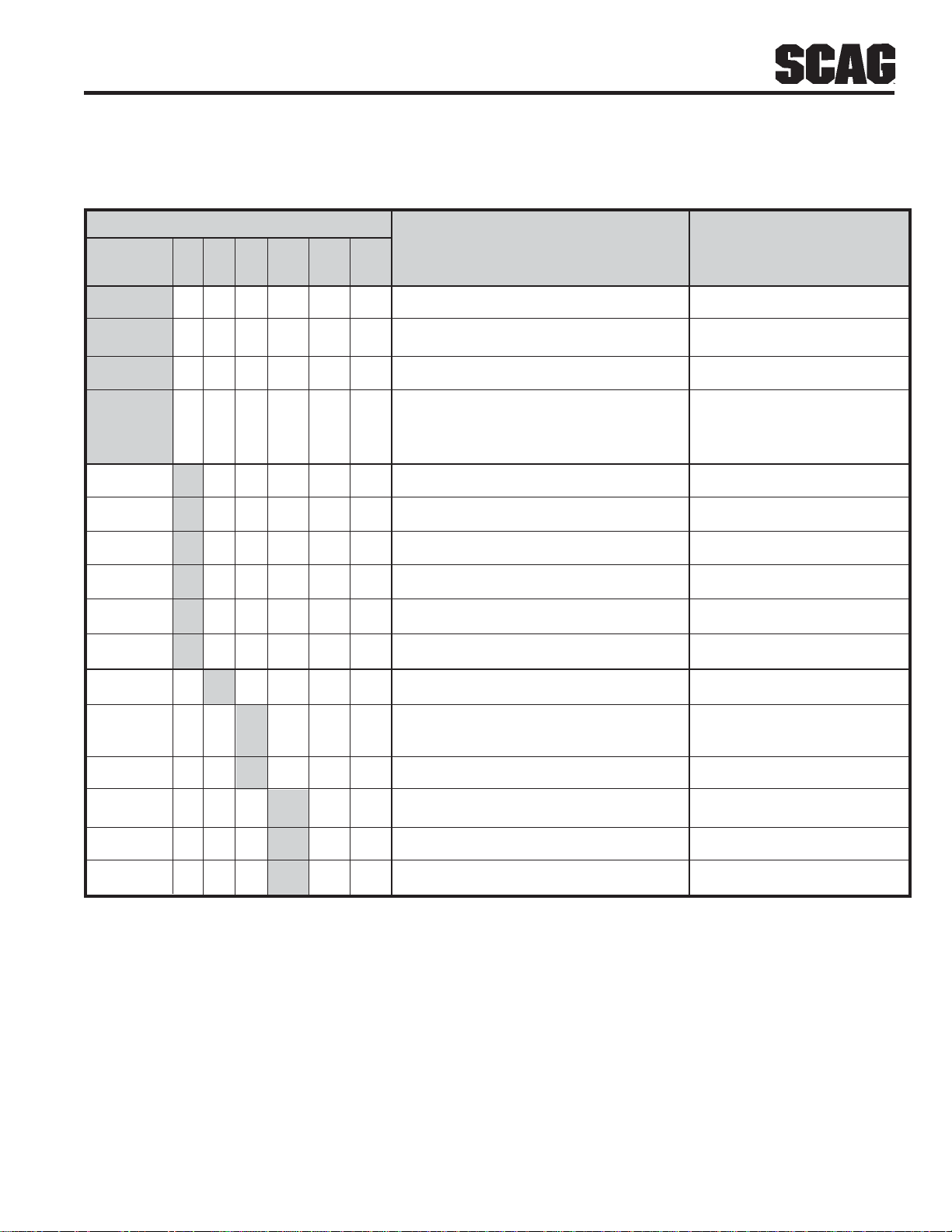
7.1 MAINTENANCE CHART - RECOMMENDED SERVICE INTERVALS
HOURS
Break-In 8 20 40 100 200 500 Procedure Comments
(First 10)
X Check all hardware for tightness
X Check hydraulic oil level See paragraph 7.3
X Check all belts for proper alignment See paragraph 7.8
X Check hydraulic hoses for leaks Use extreme caution when
checking the hydraulic hoses
See paragraph 2.6
X Check seat belts for damage See paragraph 2.5
X Check engine oil level See paragraph 7.4
X *Clean mower See paragraph 7.11
X Check condition of blades See paragraph 7.9
X Apply grease to fittings See paragraph 7.2
X Check tire pressure See paragraph 7.10
X Change engine oil and filter See paragraph 7.4
X Check battery electrolyte level, See paragraph 7.7
clean battery posts and cables
X Check belts for proper alignment See paragraph 7.8
X Apply grease to fittings See paragraph 7.2
X Change engine oil See paragraph 7.4
X *Clean air cleaner element See paragraph 7.6
* Perform these maintenance procedures more frequently under extreme dusty or dirty conditions.
29
Page 34
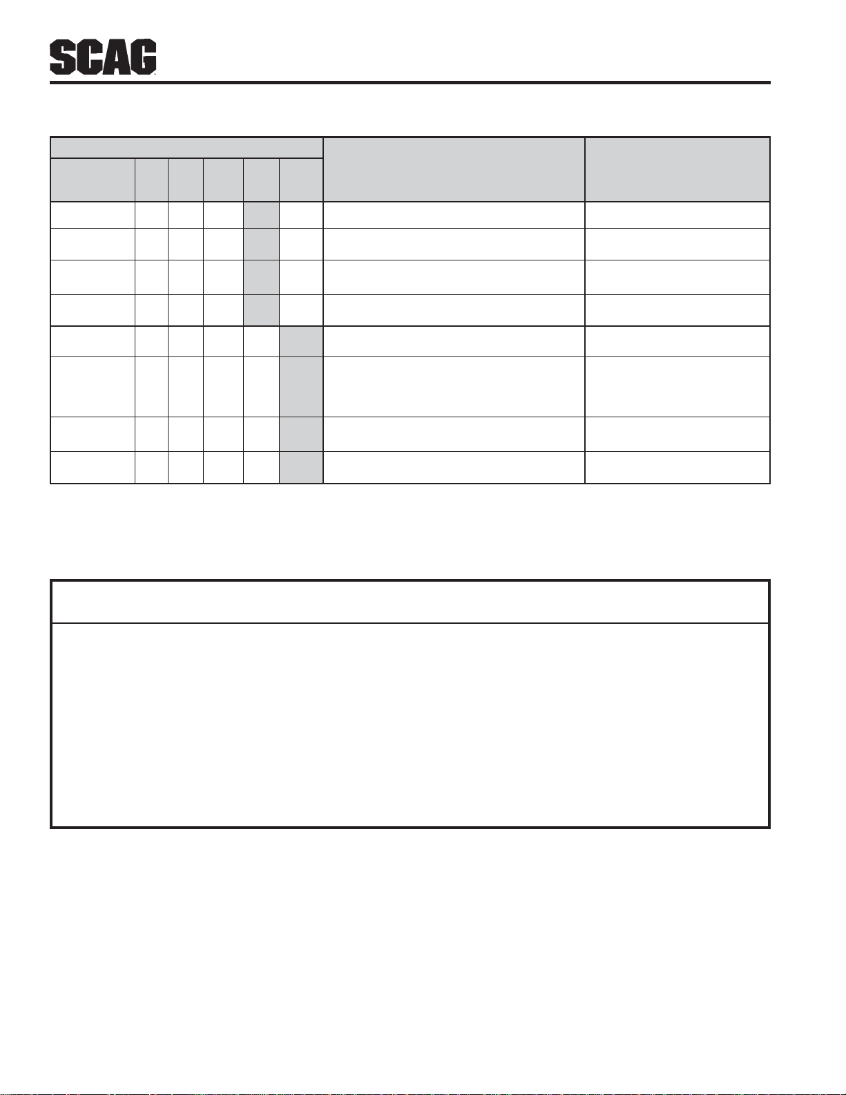
MAINTENANCE CHART - RECOMMENDED SERVICE INTERVALS (CONT'D)
HOURS
Break-In 8 40 100 200 500 Procedure Comments
(First 10)
X Apply grease to fittings See paragraph 7.2
X Check hardware for tightness
X Change engine oil filter See paragraph 7.4
X Check hydraulic oil level See paragraph 7.3
X Replace engine fuel filter See paragraph 7.5
X Drain hydraulic system and See paragraph 7.3
replace hydraulic oil Use SAE 20W50
Motor Oil
X Replace hydraulic oil filter See paragraph 7.3
X Adjust electric PTO clutch See Scag Dealer
Section 7
7.2 LUBRICATION - GREASE FITTING LUBRICATION CHART
(SEE FIGURE 7-1)
LUBRICATION NO. OF
LOCATION INTERVAL LUBRICANT PL ACES
1 Caster Wheel Pivot * 500 Hours/Yearly Chassis Grease 2
2 Caster Wheel Bearings 100 Hours/Bi-W eekly Chassis Grease 2
3 Brake Actuator 200 Hours/Monthly Chassis Grease 2
4 Cutter Deck Bellcranks 100 Hours/Bi-Weekly Chassis Grease 4
5 Cutter Deck Pusharms 100 Hours/Bi-W eekly Chassis Grease 2
6 Control Pivot 100 Hours/Bi-W eekly Chassis Grease 2
7 Cutter Deck Spindle 40 Hours/W eekly +Lithium MP White Grease 2125 3
8 Brake Handle 200 Hours/Monthly Chassis Grease 1
* PROCEDURE: Remove grease cap, part number 481559. Remove plug, part number 482028-01, and install
grease zerk. Apply grease to the fitting until new grease appears at the top of the caster extension. Remove the
grease zerk and reinstall the plug. Reinstall the grease cap. Special tool, part number 47007, is recommended for
use in the installation of the grease cap.
+ Compatible Greases: Mobilix #2 found at Mobil Service Stations
Ronex MP found at Exxon Service Stations
Super Lube MEP #2 & Super Stay-M #2 found at Conoco Stations
Shell Alvania #2 found at Shell Service Stations
Lidok EP #2 found at industrial shops
30
Page 35
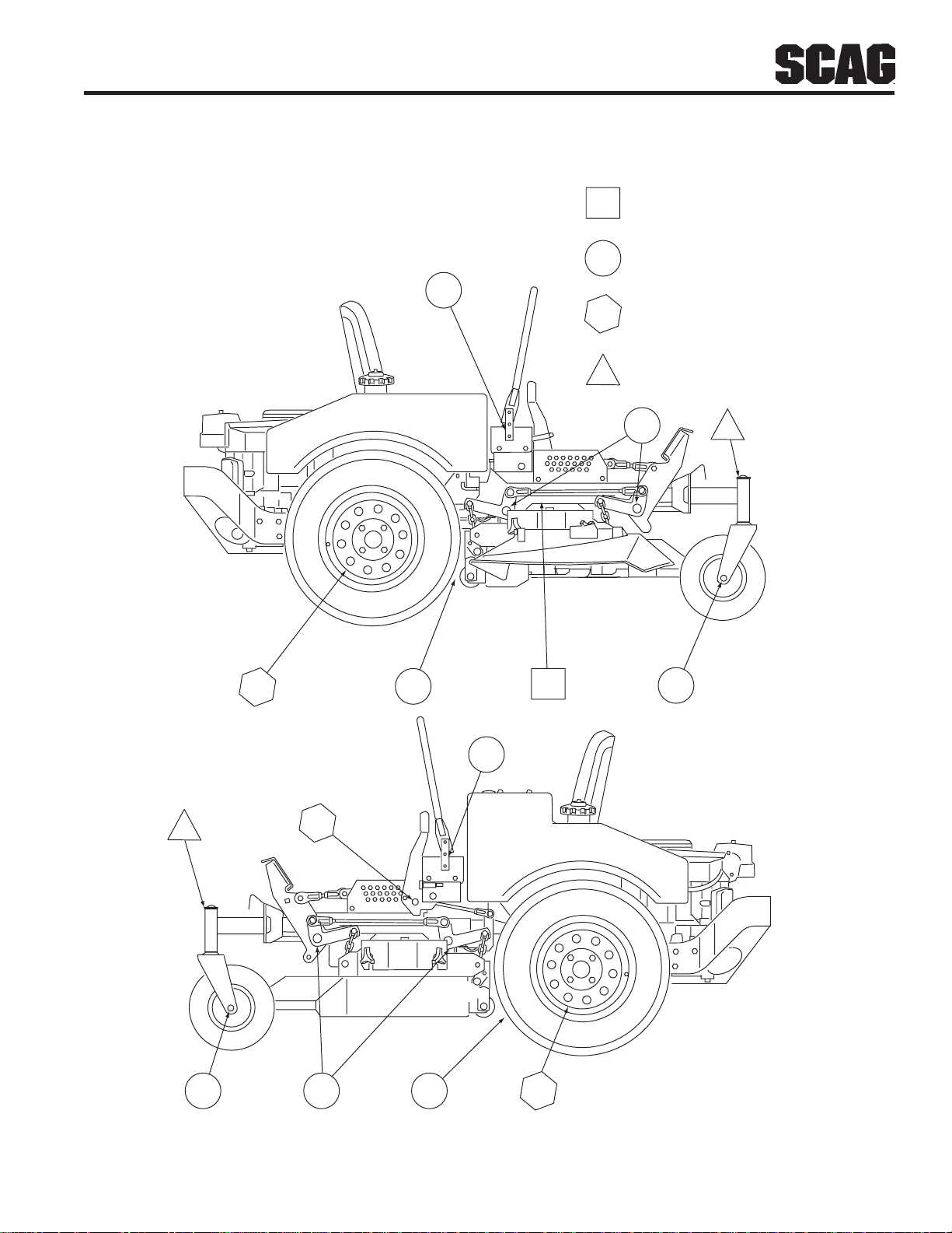
Section 7
GREASE FITTING LUBRICATION
Lubricant Interval
Lithium MP White Grease 2125
(40 Hours/Weekly)
Chassis Grease
(100 Hours/Bi-monthly)
6
Chassis Grease
(200 Hours/Monthly)
Chassis Grease
(500 Hours/Yearly)
4
3
1
8
5
6
7
2
1
3542
Figure 7.1 Lubrication Fitting Points
31
SZC 2005 LFP
Page 36
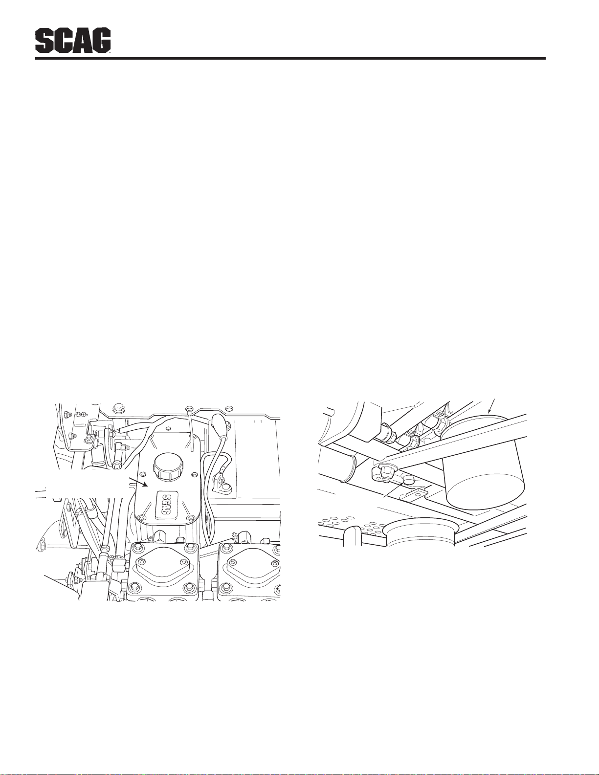
Section 7
7.3 HYDRAULIC SYSTEM
A. Checking Hydraulic Oil Level
The hydraulic oil level should be checked after the first 10
hours of operation. Thereafter, check the oil after every
200 hours of machine operation or monthly, whichever
occurs first.
-IMPORTANT-
If the oil level is consistently low, check for leaks
and correct immediately.
1. Wipe dirt and contaminants from around the reservoir
cap. Remove the cap from the hydraulic oil reservoir.
2. Visually check the level of hydraulic oil. Hydraulic oil
must be at the full tab below the filler neck. If the fluid
is low, add 20W50 motor oil. DO NOT overfill;
(overfilling the oil reservoir may cause oil seepage).
B. Changing Hydraulic Oil
The hydraulic oil should be changed after every 500 hours
or annually, whichever occurs first. The oil should also be
changed if the color of the fluid has become black or milky .
A black color and/or a rancid odor usually indicates possible
overheating of the oil, and a milky color usually indicates
water in the hydraulic oil.
-IMPORTANT-
The hydraulic oil should be changed if you notice
the presence of water or a rancid odor to the
hydraulic oil.
1. Park the mower on a level surface and stop the engine.
2. Place a suitable container under the hydraulic oil filter.
Tilt the seat forward. Remove the fill cap from the
reservoir and the drain plug from the bottom of the
reservoir. (See Figure 7-3). Allow the fluid to drain
into the container and properly discard it.
3. Clean the fill cap and install it onto the reservoir.
HYDRAULIC OIL
RESERVOIR
SZC 2005 HOR
Figure 7-2 Hydraulic Oil Reservoir
HYDRAULIC
OIL FILTER
HYDRAULIC OIL
DRAIN PLUG
SZC 2005 HODP
Figure 7-3 Hydraulic Oil Filter and Drain Plug
3. Re-install the drain plug into the tee fitting and be sure
it is tight.
-NOTE-
Before refilling the hydraulic oil reservoir the
hydraulic oil filter should be changed as outlined
in section C -Changing Hydraulic Oil Filter
Element- on the next page.
32
Page 37
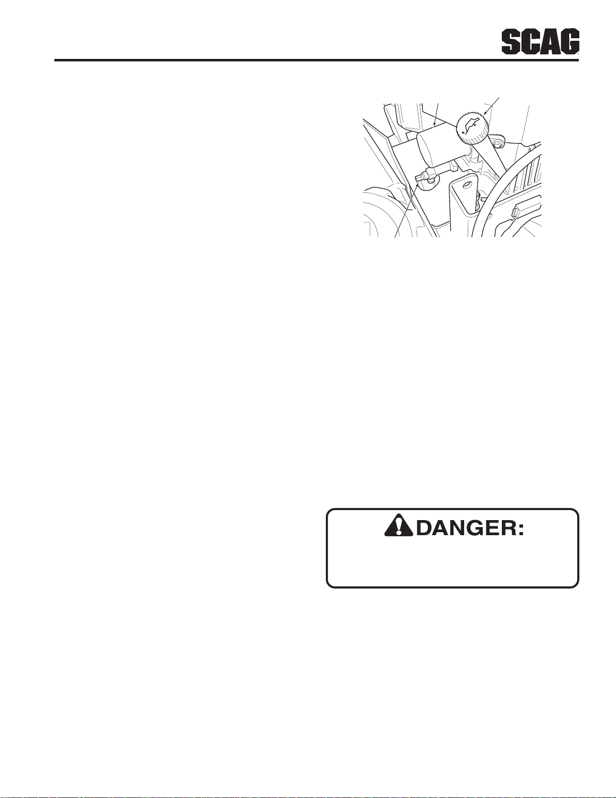
Section 7
4. Fill the reservoir to the full tab below the filler neck
with SAE 20W50 motor oil.
5. Replace the reservoir fill cap. Start the engine and
drive forward and backward for two minutes. Check
the oil level in the reservoir. If necessary , add oil to the
reservoir.
C. Changing Hydraulic Oil Filter Element
The hydraulic oil filter should be changed after every 500
hours of operation or annually , whichever occurs first.
1. Remove the oil filter element (Figure 7-3, Page 32)
and properly discard it. Fill the new filter with clean
SAE 20W50 engine oil and install the filter . Hand tighten
only .
2. Run the engine at idle speed with the speed control
lever in neutral for five minutes.
3. Check the oil level in the hydraulic tank. It must be
3-1/4" inches from the top of the filler neck. If
necessary , add SAE 20W50 motor oil.
7.4 ENGINE OIL
ENGINE OIL
FILTER
ENGINE OIL
DRAIN PLUG
ENGINE OIL
FILLER
SZC 2005 EOFD
Figure 7-5 Kawasaki Engine Oil Fill/Dipstick,
Filter and Drain Plug Locations
C. Changing Engine Oil Filter
After the first 10 hours of operation, replace the engine oil
filter. Thereafter, replace the oil filter after every 200 hours
of operation or every month, whichever occurs first. Refer
to Engine Operator’s Manual for instructions.
-NOTE-
The engine oil filter for the Honda engine is
supplied by Scag Power Equipment. Use only the
part number listed in the illustrated parts list of
this manual when replacing.
A. Checking Engine Crankcase Oil Level
The engine oil level should be checked after every 8 hours
of operation or daily as instructed in the Engine Operator’s
Manual furnished with this mower.
B. Changing Engine Crankcase Oil
After the first 20 hours of operation, change the engine
crankcase oil and replace the oil filter. Thereafter , change
the engine crankcase oil after every 100 hours of operation
or bi-weekly, whichever occurs first. Refer to the Engine
Operator’s Manual furnished with this mower for
instructions.
7.5 ENGINE FUEL SYSTEM
T o a v oid injury fr om burns, allow the mower to
cool before removing the fuel tank cap and
refueling.
A. Filling the Fuel Tank
Fill the fuel tank at the beginning of each operating day to
within 1 inch below the filler neck. Do not overfill. Use
clean, fresh unleaded gasoline with a minimum octane
rating of 87.
T o avoid personal injury or property damage, use
extreme care in handling gasoline. Gasoline is extremely
flammable and the vapors are explosive.
33
Page 38
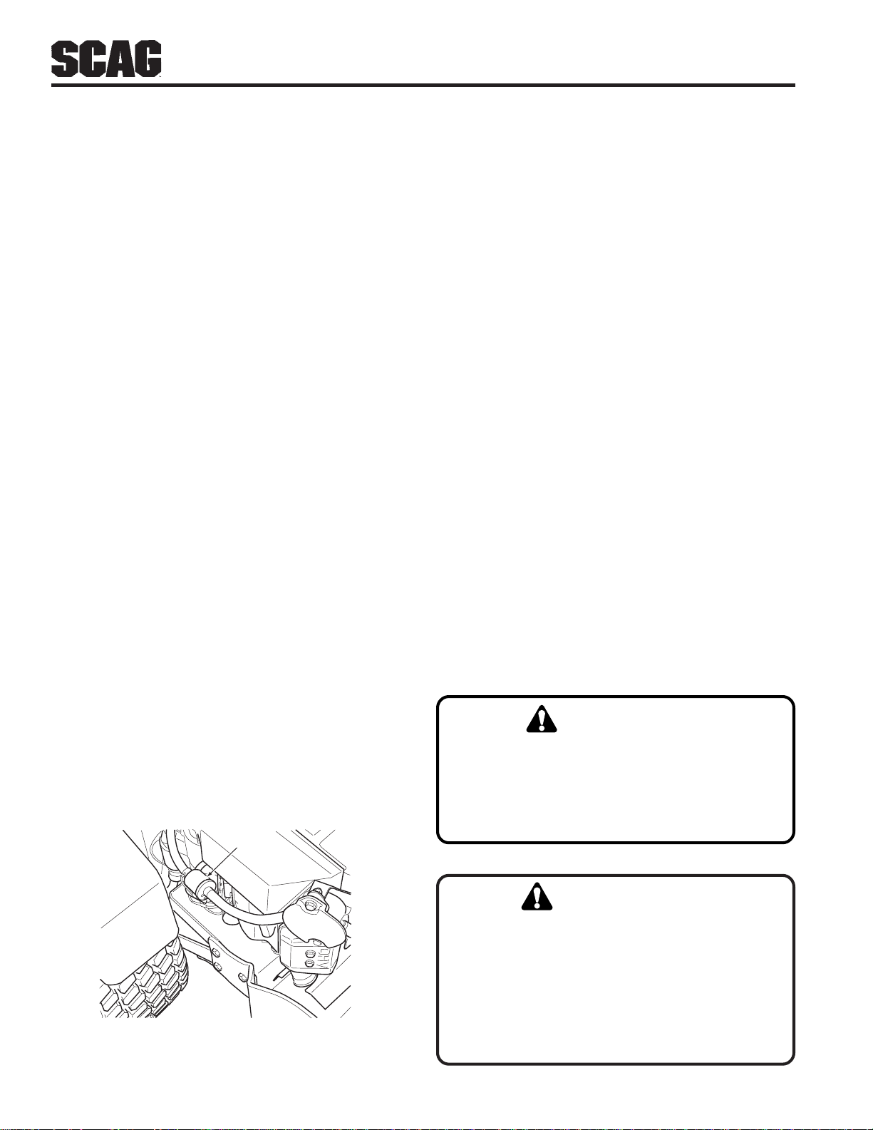
Section 7
1. Extinguish all cigarettes, cigars, pipes and other
sources of ignition.
2. Use only an approved gasoline container.
3. Never remove the gas cap or add fuel with the
engine running. Allow the engine to cool before
fueling.
4. Never fuel the machine indoors or in an enclosed
trailer.
5. Never store the machine or fuel container where
there is an open flame, spark or pilot light such as on
a water heater or other appliances.
6. Never fill containers inside a vehicle or on a truck or
trailer bed with a plastic liner. Always place
containers on the ground away from your vehicle
before filling.
7.6 ENGINE AIR CLEANER
A. Cleaning and/or Replacing Air Cleaner
Element
For any air cleaner, the operating environment dictates
the air cleaner service periods. Inspect and clean the air
cleaner element after every 100 hours of operation or
bi-weekly, whichever occurs first and replace the
element if required.
-NOTE-
In extremely dusty conditions it may be necessary
to check the element once or twice daily to
prevent engine damage.
1. Release the two latches securing the air cleaner
cover to the air cleaner assembly and remove the
cover. Set aside.
2 Remove the air cleaner and inspect.
7. Remove the machine from the truck or trailer and
fuel on the ground. If this is not possible, then refuel
the machine with a portable container, rather than
from a gasoline dispenser nozzle.
8. Keep the nozzle in contact with the rim of fuel tank
or container opening at all times until fueling is
complete. Do not use a nozzle lock-open device.
9. If fuel is spilled on clothing, change clothing
immediately and wash affected skin.
10. Replace gas cap and tighten securely.
FUEL
FILTER
SZC 2005 EFF
Figure 7-6 Engine Fuel Filter Location
3. Clean or replace the air cleaner and foam
pre-cleaner as recommended by the engine
manufacturer.
7.7 BATTERY
WARNING:
Battery posts, terminals, and related accessories contain lead and lead compounds,
chemicals known to the State of California
to cause cancer and reproductive harm.
Wash hands after handling.
WARNING:
Lead-acid batteries produce flammable and
explosive gases. To av oid personal injury
when checking, testing or charging
batteries, DO NOT use smoking materials
near batteries. Keep arcs, sparks and flames
away from batteries. Provide proper
ventilation and wear safety glasses.
34
Page 39
Section 7
WARNING:
Electric storage battery fluid contains sulfuric
acid which is POISON and can cause SEVERE
CHEMICAL BURNS. Avoid contact of fluid
with eyes, skin, or clothing. Use proper
protective gear when handling batteries. DO
NOT tip any battery beyond 45° angle in any
direction. If fluid contact does occur, follow
first aid suggestions below.
A. Charging the Battery
Refer to the battery charger’s manual for specific
instructions.
Under normal conditions the engine’ s alternator will have
no problem keeping a charge on the battery. If the
battery has been completely discharged for a long period
of time, the alternator may not be able to recharge the
battery, and a battery charger will be required.
BATTERY ELECTROLYTE FIRST AID
EXTERNAL CONTACT — Flush with water.
EYES — Flush with water for at least 15
minutes and get medical attention
immediately.
INTERNAL — Drink large quantities of water.
Follow with Milk Of Magnesia, beaten egg,
or vegetable oil. Get medical attention
immediately. In case of internal contact, DO
NOT give fluids that would induce vomiting.
DO NOT charge a frozen battery. It may explode and
cause injury. Let the battery warm before attaching a
charger.
Whenever possible, remove the battery from the mower
before charging and make sure the electrolyte covers the
plates in all cells.
WARNING:
BATTERIES PRODUCE EXPLOSIVE GASES.
Charge the battery in a well ventilated space
so gases produced while charging can
dissipate.
Charging rates between 3 and 50 amperes are satisfactory
if excessive gassing or spewing of electrolyte does not occur
or the battery does not feel excessively hot (over 125°F).
If spewing or gassing occurs or the temperature exceeds
125°F, the charging rate must be reduced or temporarily
stopped to permit cooling.
B. Jump Starting
1. The booster battery must be a 12 volt type. If a vehicle
is used for jump starting, it must have a negative ground
system.
2. When connecting the jumper cables, connect the
positive cable to the positive battery post, then connect
the negative cable to the negative battery post.
35
Page 40
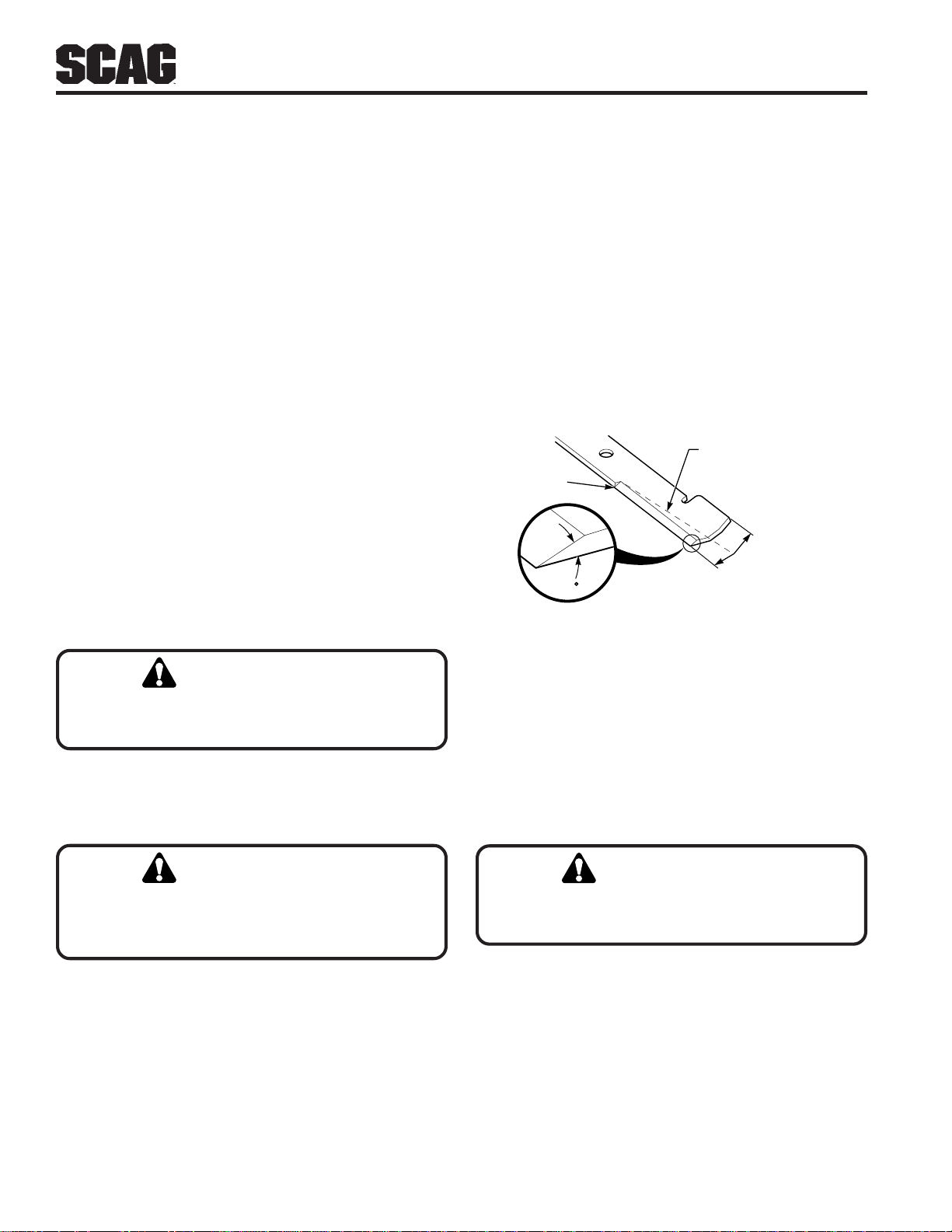
Section 7
7.8 DRIVE BELTS
All drive belts are spring-loaded and self-tensioning,
however after the first 2, 4, 8 and 10 hours of operation,
the belts should be checked for proper alignment and wear.
Thereafter, check the belts after every 40 hours of operation
or weekly, whichever occurs first.
-NOTE-
If you experience frequent belt wear or breakage,
see your authorized Scag Dealer for belt
adjustment.
7.9 CUTTER BLADES
A. Blade Inspection
1. Remove the ignition key before servicing the blades.
2. Raise the mower deck to the highest position. Place
the lanyard pin in the highest cutting height positon to
prevent the cutter deck from falling.
B. Blade Sharpening
-NOTE-
If possible, use a file to sharpen the blade. Using
a wheel grinder may burn the blade.
-NOTE-
DO NOT sharpen the blades beyond 1/3 of the width
of the blade.
1. Sharpen the cutting edge at the same bevel as the
original (See Figure 7-9). Sharpen only the top of the
cutting edge to maintain sharpness.
Angle Blade Back
Do Not Cut In
X
X Must NOT Exceed
30
1/3 Blade Width
SGB033
WARNING:
Always wear proper hand and eye protection
when working with cutter blades.
3. Check the cutter blades for straightness. If the cutter
blades appear bent, they will need to be replaced.
WARNING:
Do not attempt to straighten a bent blade, and
never weld a broken or cracked blade. Always
replace it with a new blade to assure safety.
4. If a blade cutting edge is dull or nicked, it should be
sharpened. Remove the blades for sharpening. See
"Blade Replacement."
-NOTE-
Keep the blades sharp. Cutting with dull blades
not only yields a poor mowing job, but slows the
cutting speed of the mower and causes extra wear
on the engine and the blade drive.
Figure 7-9 Blade Sharpening
2. Check the balance of the blade. If the blades are out
of balance, vibration and premature wear can occur.
See your authorized Scag dealer for blade balancing
or special tools, if you choose to balance your own
blades.
C. Blade Replacement
WARNING:
Always wear proper hand and eye protection
when working with cutter blades.
1. Remove the ignition key before replacing the blades.
2. Raise the mower deck to the highest position. Place
the lanyard pin in the highest cutting height positon to
prevent the cutter deck from falling.
36
Page 41
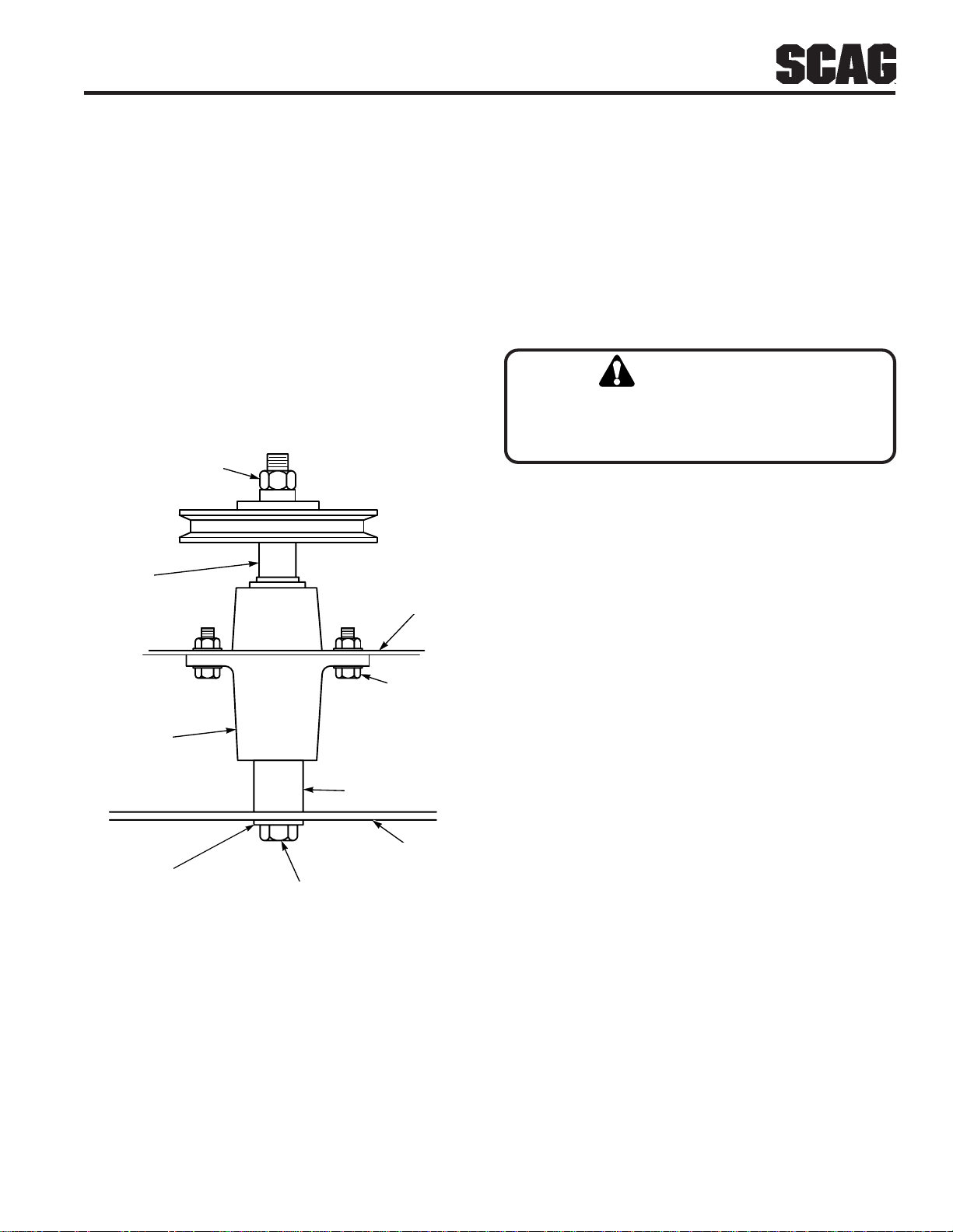
Section 7
3. Secure the cutter blades to prevent them from rotating,
(Use the optional Blade Buddy tool, P/N 9212, to assist
in securing the cutter blades), remove the nut from the
blade attaching bolt. Remove the cutter blade, bolt
and spacer from the spindle shaft. (Figure 7-10).
-NOTE-
The front of the machine will have to be raised
slightly to remove the blade bolt from the cutter
spindle.
4. T o install the new cutter blade, put the flat washer onto
the blade bolt and slide the bolt into the hole in the
cutter blade.
HEX NUT-TORQUE
TO 75 LB-FT
SPINDLE
SHAFT
CUTTER
DECK
7.10 TIRES
Check the tire pressures after every 8 hours of operation
or daily.
Caster Wheels ........................................ Flat Free
Drive Wheels ......................................... 12 PSI
7.11 BODY, DECK, AND UPHOLSTERY
CAUTION:
Do not wash any portion of the equipment
while it is hot. Do not wash the engine; use
compressed air .
1. After each use, wash the mower and cutter deck. Use
cold water and automotive cleaners. Do not use
pressure cleaners.
2. Do not spray electrical components.
HEX HEAD
BOLT / NUT
SPINDLE
ASSEMBLY
CUTTER BLADE
SPACER
CUTTER
WASHER
HEX HEAD BOLT
BLADE
390S0160
Figure 7-10 Blade Replacement
-NOTE-
Be sure that the blade is installed with the lift wing
toward the top of the cutter deck.
5. Install the spacer onto the blade bolt and insert the bolt
into the cutter spindle shaft.
3. Use a mild soap solution or a vinyl/rubber cleaner to
clean the seat.
4. Repair damaged metal surfaces using Scag touch-up
paint (P/N 48521) available from your authorized Scag
dealer. Wax the mower with an automotive paint wax
for maximum paint protection.
6. Install the hex nut to the blade bolt at the top of the
cutter spindle. Secure the blades from rotating and
torque to 75 ft-lbs. (See Figure 7-10)
37
Page 42
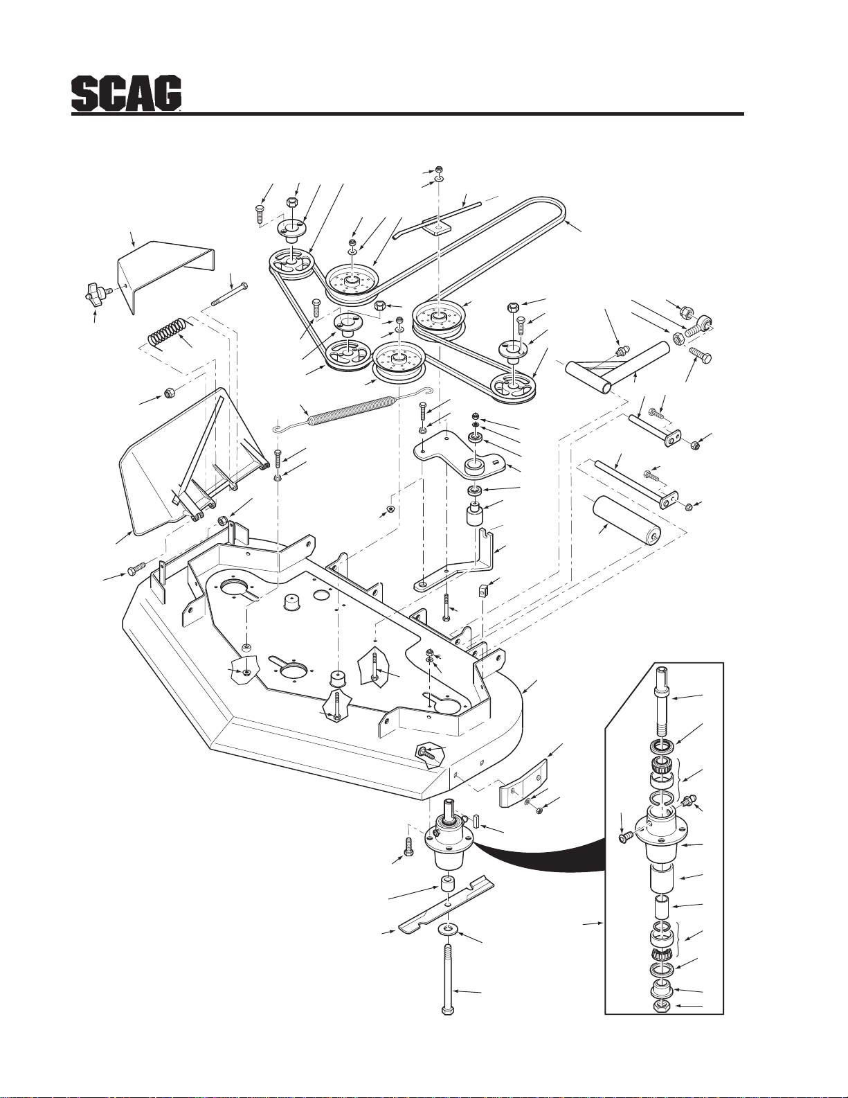
36A”& 42A" CUTTER DECKS
Section 8
54
50
58
55
51
52
53
51
3
56
2
4
5
45
6
7
8
23
24
24
2
6
7
8
7
3
6
23
24
64
57
A
27
26
A
63
6
7
21
22
21
9
13
20
10
12
11
19
15
16
17
14
18
17
18
3
2
4
5
24
46
31
30
29
47
49
48
59
25
32
33
28
1
61
60
62
34
SZC 2006 CD
39
35
36
37
38
40
41
42
37
43
44
45
38
Page 43

Section 8
36A”& 42A" CUTTER DECKS
Ref. Part
No. No. Description 3 6 42
1 461850 Cutter Deck (incl. decals) x
461851 Cutter Deck (incl. decals) x
2 04015-14 Bolt, Hex Head 1/4-20 x 3/4” x
04001-172 Bolt, Hex Head 1/4-20 x 1” x
3 04020-09 Nut, 5/8-11 x x
4 48926 Tapered Hub, 1.125” Bore x x
5 483110 Pulley, 4.15 O.D. (36”) x
482646 Pulley, 4.75 O.D. (42”) x
6 04021-09 Nut, Elastic Stop 3/8-16 x
7 04043-04 Flatwasher, 3/8-.391 x .938 x .105 x x
8 483215 Pulley, 5” Idler x x
9 483001 Belt, Cutter Deck (36”) x
483002 Belt, Cutter Deck (42”) x
10 48114-04 Grease Fitting 1/4-28 Self Tapping x x
11 04020-08 Nut, 1/2-20 UNF x x
12 48542 Rod End, 1/2-20 RH Thread x x
13 04021-07 Nut, Elastic Stop 1/2-13 x x
14 04001-87 Bolt, Hex Head 1/2-13 x 4” x x
15 461769 Push Arm Assembly (incl. 10, 11, 12) x x
16 451240 Rod Weldment, Push Arm x x
17 04001-09 Bolt, Hex Head 5/16-18 x 1” x x
18 04019-03 Nut, Serrated Flange 5/16-18 x x
19 45944 Shaft Weldment, Guide Roller x x
20 48038 Roller x x
21 48224 Bearing x x
22 461632 Idler Arm Assembly (incl. item 21) x x
23 04001-136 Bolt, Hex Head 3/8-16 x 1-1/2” Gr. 8 x x
24 04019-04 Nut, Serrated Flange 3/8-16 x x
25 04001-54 Bolt, Hex Head 3/8-16 x 3” x x
26 43660 Pivot, Idler x x
27 04110-03 U-Nut, 3/8-16 x x
28 04063-20 Key, 1/4 x 1/4 x 1” x x
29 04001-176 Bolt, 5/16-18 x 1-3/4” Gr. 8 x x
30 43590 Spacer, Spindle x x
31 482959 Cutter Blade, 12.20” x
483014 Cutter Blade, 14-3/4” x
32 04043-06 Flatwasher, 5/8-.688 x .75 x .134 HD x x
33 04001-180 Bolt, Hex Head 5/8-11 x 8-1/2” x
04001-41 Bolt, Hex Head 5/8-11 x 9-1/2” x
34 461776 Spindle Assembly (36”) x
461663 Spindle Assembly x
Ref. Part
No. No. Description 3 6 42
35 43663 Shaft, Cutter Spindle (36”) x
43589 Shaft, Cutter Spindle x
36 481024 Seal, Top x x
37 481022 Bearing Assembly x x
38 48114-04 Grease Fitting x x
39 48677 Relief Fitting, Tapered Spindle x x
40 43644 Spindle Housing x x
41 43312 Spacer, Outside x x
42 43296 Spacer, Inside x x
43 481025 Seal, Bottom x x
44 43297 Spindle Bushing, Bottom x x
45 481035 Nut, Special 1 - 1/16-18 x x
46 04001-23 Bolt, 3/8-16 x 4-1/2” x x
47 04001-77 Bolt, 3/8-16 x 3-1/2” x x
48 04030-03 Lock washer, 5/16” x x
49 04021-22 Nut, Elastic Stop 5/16-18 Gr. 8 x x
50 04001-11 Bolt, 5/16-18 x 1-1/2” x x
04001-12 Bolt, 5/16-18 x 1-3/4” x x
51 04021-10 Nut, Elastic Stop 5/16-18 x x
52 482245 Spring, Discharge Chute x x
53 04001-154 Bolt, Hex Head 5/16-18 x 4-3/4” x x
54 481625-01 Knob w/stud, 3/8-16 x 1-1/4” x x
55 424055 Belt Cover x
56 483112 Spring x x
57 483210 Pulley, 5” Idler x x
58 461295 Discharge Chute x x
59 04003-12 Bolt, Carr. 5/16-18 x 3/4” x x
60 483175 Wear Pad x x
61 04040-04 Flatwasher x x
62 04021-04 Nut, Center Lock 5/16-18 x x
63 424411 Bracket, Belt Guide x x
64 451839 Rod, Belt Guide x x
39
Page 44
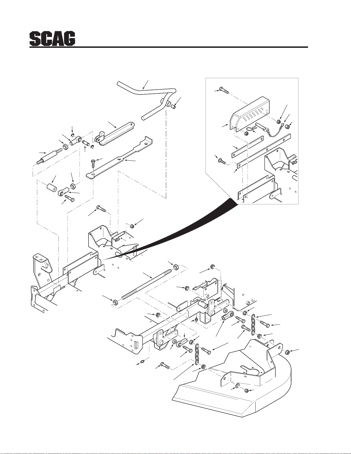
CUTTER DECK CONTROLS
8
Section 8
9
11
7
10
16
5
4
2
1
12
14
6
3
13
15
20
26
27
28
19
29
18
17
30
2
32
36
3
36
24
34
23
34
35
31
23
22
31
33
31
CUTTER DECK
34
25
31
35
34
31
34
31
21
SZC 2005 CDC
40
Page 45

Section 8
CUTTER DECK CONTROLS
Ref. Part
No. No. Description
1 483136 Link, Deck Lift
2 04020-28 Nut, 1/2-20 UNF LH Thread Jam
3 04020-27 Nut, 1/2-20 UNF RH Jam
4 483134 Rod End, 1/2-20 LH Female
5 04050-10 Ring, Retaining 1/2” External “E”
6 43487 Pin, Deck Lift
7 483062 Slide, Deck Height Adjust
8 451703 Deck Latch Weldment
9 43668 Bushing, .502 O.D.
10 422346 Lock Plate, Deck Lift
11 04014-03 Screw, Cap 5/16-18 x 3” FHHS
12 43666 Spacer, Foot Pedal SZC
13 483135 Rod End, 1/2-20 RH Female
14 04001-145 Bolt, Hex Head 1/2-13 x 3-1/2”
15 04001-31 Bolt, Hex Head 3/8-16 x 2-1/2”
16 04021-09 Nut, Elastic Stop 3/8-16
17 04003-04 Bolt, Carriage 5/16-18 x 1”
18 422381 Guide, Short
19 423463 Bracket, Cutting Height Adjustment
20 04001-77 Bolt, Hex Head 3/8-16 x 3-1/2”
21 04021-09 Nut, Elastic Stop 3/8-16
22 483130 Rod End, 1/2-20 RH Female
23 48114-04 Grease Fitting, 1/4-28 Self Tap
24 43432 Spacer
25 04041-07 Flatwasher, 3/8-.391 x .938 x .105
26 04019-04 Nut, Serr. Flange 3/8-16
27 04067-09 Pin
481547 Lanyard
28 04021-09 Nut, Elastic Stop 3/8-16
29 04062-04 Hair Pin Cotter, .177 x 3-1/4”
30 422380 Guide, Long
31 04019-04 Nut, Serr. Flange 3/8-16
32 483132 Link, Lift 1/2-20 x 14.18”
33 483131 Rod End, 1/2-20 LH Female
34 04001-20 Bolt, Hex Head 3/8-16 x 1-1/2”
35 48540 Chain
36 04021-23 Nut, Center Lock 5/8-11
41
Page 46
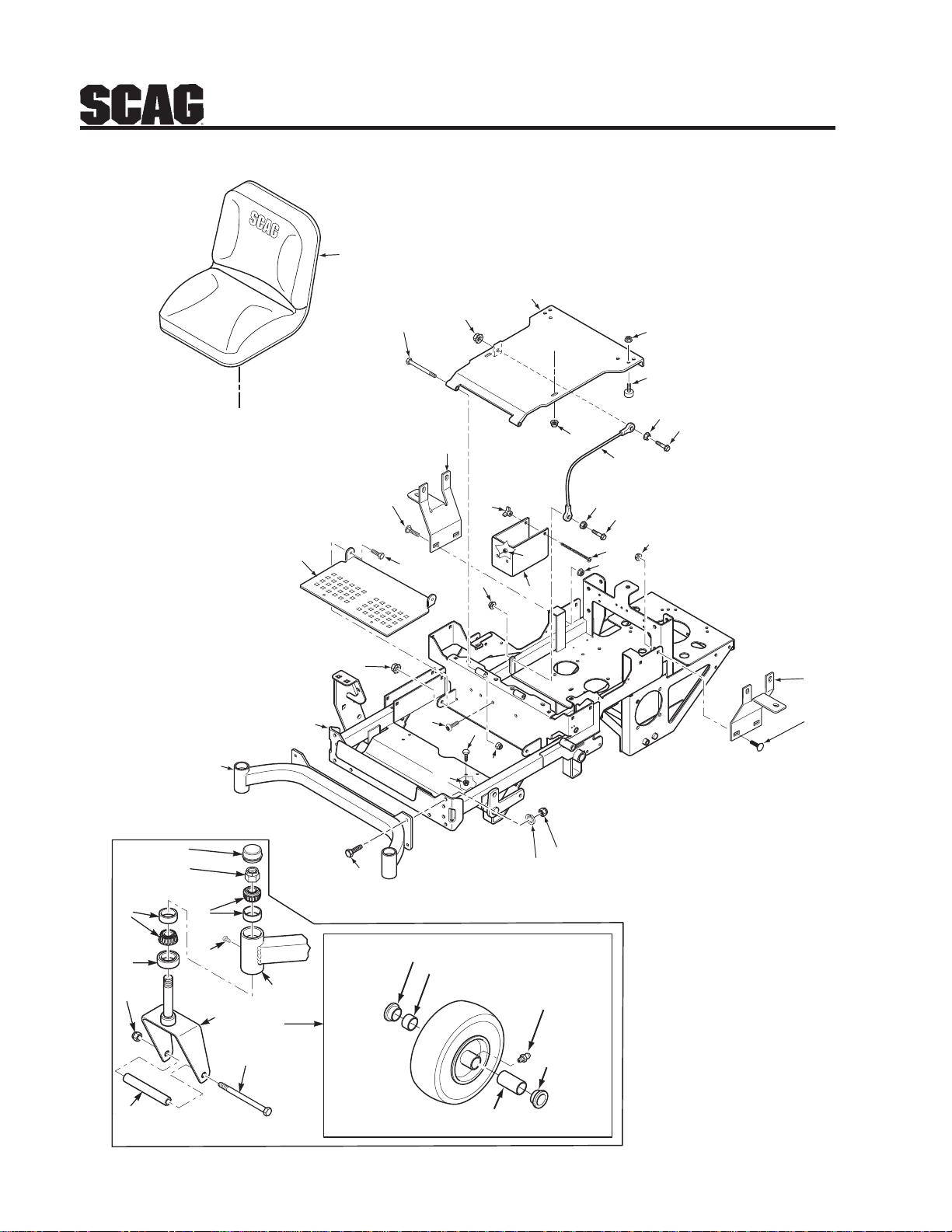
SHEET METAL COMPONENTS
1
3
2
33
A
Section 8
36
4
18
19
17
A
15
36
33
10
16
11
13
35
14
6
9
28
12
36
33
4
7
39
38
34
33
31
37
31
10
8
6
9
20
22
23
25
20
21
24
26
17
27
29
30
32
29
SZC 2006 SMC
5
42
Page 47

Section 8
SHEET METAL COMPONENTS
Ref. Part
No. No. Description
1 483116 Seat Assembly
2 04001-51 Bolt, Hex Head 3/8-16 x 3-3/4”
3 451732 Seat Mounting Base Weldment
4 481284 Bumper, Rubber
5 481769 Roller Bearing, .625 x 3-1/4”
6 424200 Bracket, Fuel Tank Mounting
7 04029-01 Wing Nut, 1/4-20
8 04003-39 Bolt, Carriage 1/4-20 x 6”
9 04003-12 Bolt, Carriage 5/16-18 x 3/4”
10 04019-03 Nut, Serr. Flange 5/16-18
11 423557 Foot Plate
12 04104-01 Bolt, Torx 3/8-16 x 1”
13 461835 Mainframe Weldment
14 04001-28 Bolt, Hex Head 7/16-14 x 1-1/4”
15 04030-05 Lockwasher, 7/16”
16 04021-11 Nut, Elastic Stop 7/16-14
17 451728 Caster Support Weldment - 36”
451729 Caster Support Weldment - 42”
18 481559 Cap, Grease
19 04021-20 Nut, Elastic Stop 1”-14 Jam
20 48668 Bearing w/Race
21 482028-01 Plug, 1/4-28 Self Tap
22 481025 Seal, 2” O.D. x 1.625 I.D.
23 04021-07 Nut, Elastic Stop 1/2-13
24 451727 Caster Yoke Weldment
25 43511 Sleeve, Caster Wheel
26 04001-80 Bolt, Hex Head 1/2-13 x 6-1/2”
27 9276 Caster Wheel Assy. (incl. 5, 29, 30, 32)
28 04001-19 Bolt, Hex Head 3/8-16 x 1”
29 481770 Bearing, Oilite
30 481846 Roller Bearing, .625 x 1”
Ref. Part
No. No. Description
31 04001-59 Bolt, Hex Head 1/4-20 x 1-1/4”
32 48114-05 Grease Fitting, 1/4-28 Straight
33 04019-02 Nut, Serr. Flange 1/4-20
34 04021-10 Nut, Elastic Stop 5/16-18
35 04021-09 Nut, Elastic Stop 3/8-16
36 04019-03 Nut, Serr. Flange 5/16-18
37 48566 Cable, Seat Stop
38 424058 Battery Box
39 04019-04 Nut, Serr. Flange 3/8-16
43
Page 48
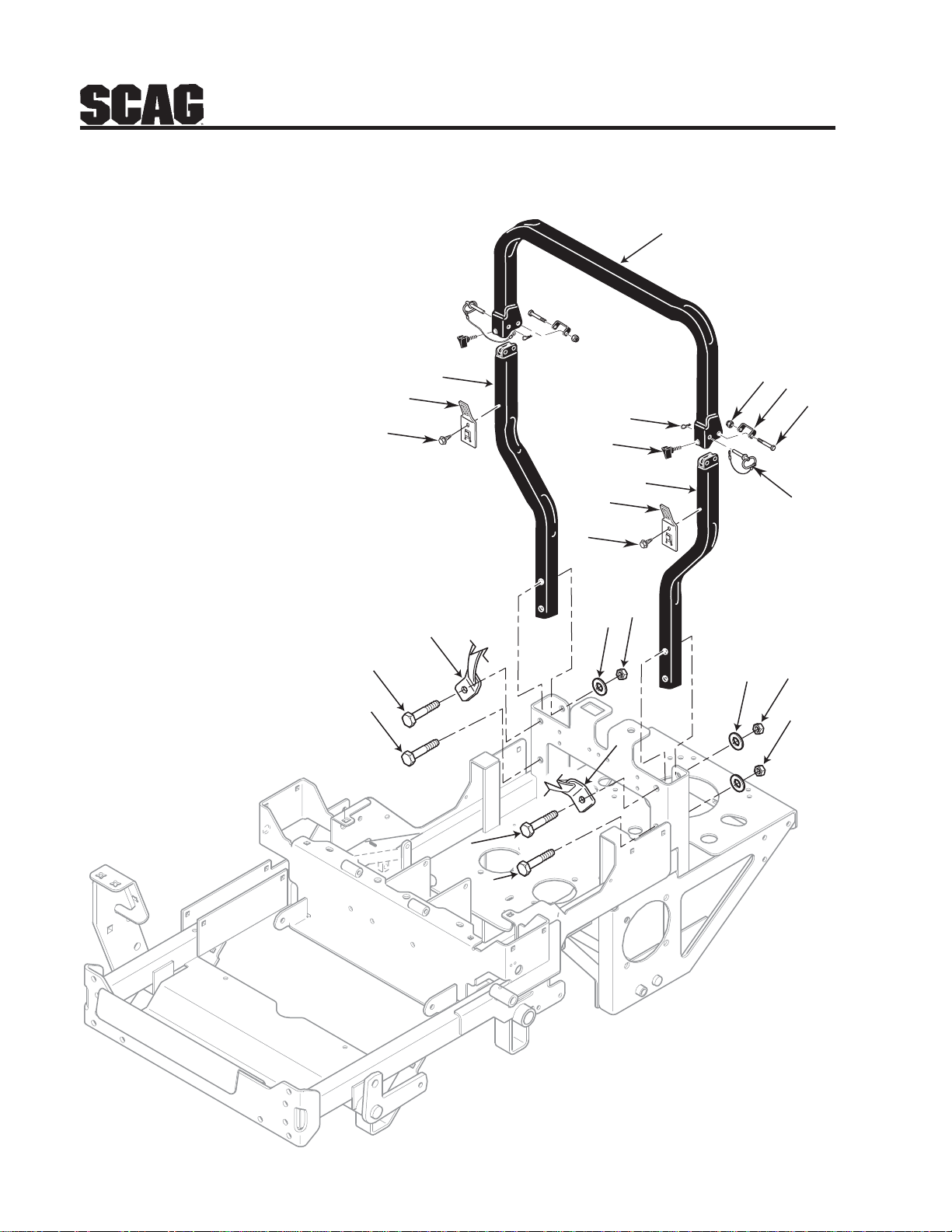
SZC ROLL-OVER PROTECTION SYSTEM
1
Section 8
1
12
12
7
6
1
5
4
2
13
13
2
3
3
9
10
11
8
5
4
5
44
3
3
2005 SZC ROPS
Page 49

Section 8
SZC ROLL-OVER PROTECTION SYSTEM
Ref. Part
No. No. Description
1 483140 SZC ROPS
2 483150 Seat Belt, ROPS
3 04001-145 Bolt, Hex Head 1/2-13 x 3-1/2”
4 04040-13 Flatwasher, 1/2-.562 x 1.375 x .109
5 04021-19 Nut, Center Lock 1/2-13
6 481625-03 Thumb Screw, 5/16-18 NC x 3-4”
7 04062-06 Hair Pin, Cotter
8 483262 Pin
9 04021-19 Nut, Center Lock 1/2-13
10 424407 Bracket, Stop
11 04001-145 Bolt, Hex Head 1/2-13 x 3-1/2”
12 424400 Bracket, Seat Belt Hanger
13 04011-13 Screw, 1/4-20 x 3/4”
45
Page 50
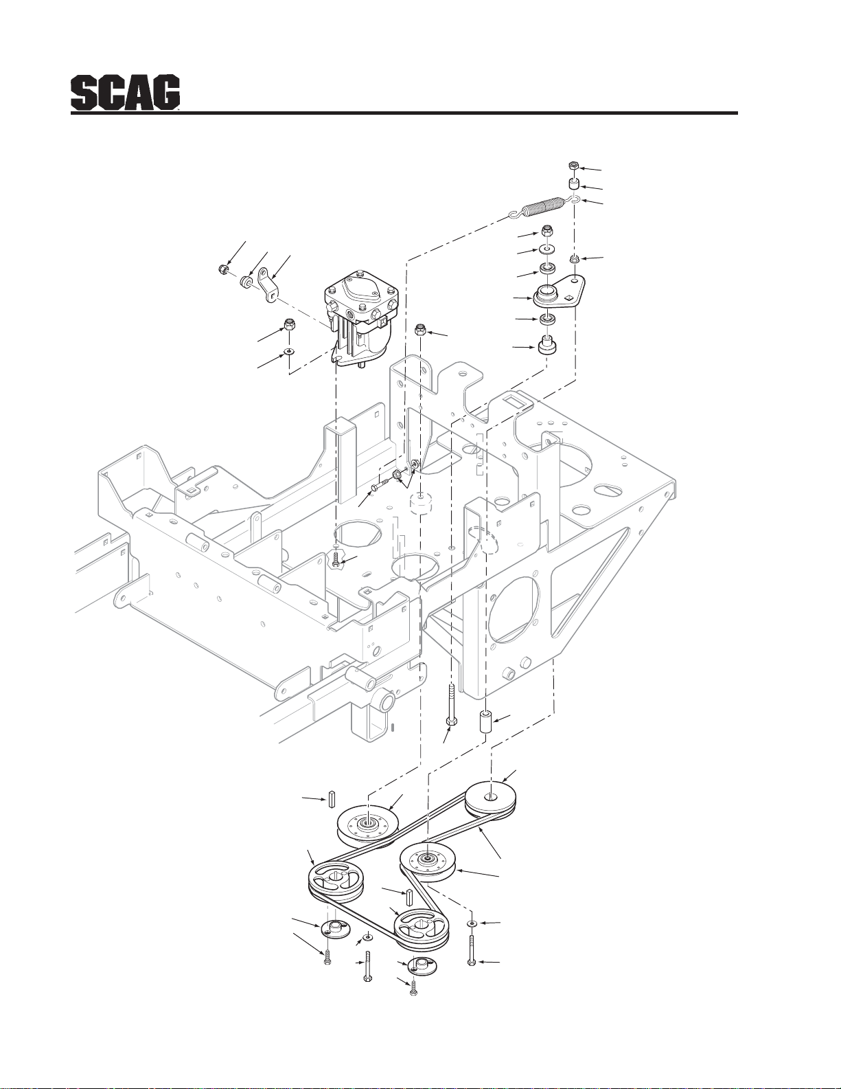
DRIVE SYSTEM COMPONENTS
C
Section 8
5
3
2
27
26
23
24
25
21
18
22
1
10
15
6
15
1
14
22
12
16
4
20
19
7
11
12
16
28
8
9
10
17
SZC 2006 DS
7
11
10
13
46
Page 51

Section 8
DRIVE SYSTEM COMPONENTS
Ref. Part
No. No. Description
1 04021-09 Nut, Elastic Stop 3/8-16
2 483088 Spring, SZC Pump Drive
3 43212 Sleeve
4 43674 Spacer, Pump Idler
5 04021-05 Nut, Center Lock 3/8-16
6 49922 Idler Arm Assembly, Pump Drive
7 04063-14 Key, 5 x 5 x 25mm
8 483164 Belt, Pump Drive SZC
9 483208 Pulley, Idler 3” Dia.
10 04043-04 Flatwasher, 3/8-.391 x .938 x .105 HD
11 482649 Pulley, 5.45 O.D. Tapered Bore
12 482085 Hub, Tapered, 15mm Bore
13 04001-45 Bolt, Hex Head 3/8-16 x 2”
14 43503 Pivot, Idler Short
15 48224 Bearing
16 04001-172 Bolt, Hex Head 1/4-20 x 1” Grade 8 Black
17 04001-62 Bolt, Hex Head 3/8-16 x 3-1/4”
18 04001-20 Bolt, Hex Head 3/8-16 x 1-1/2”
19 482968 Pulley, 5.45” Dia. 1” Bore
20 04001-31 Bolt, Hex Head 3/8-16 x 2-1/2”
21 04001-136 Bolt, Hex Head 3/8-16 x 1-1/4 Grade 8 Black
22 04019-04 Nut, Serr. Flange 3/8-16
23 04021-12 Nut, Center Lock 5/16-24
24 483123 Retainer, Pump Lever
25 424061 Control Lever, Pump
26 04043-04 Flatwasher, 3/8-.391 x .938 x .105
27 04021-09 Nut, Elastic Stop 3/8-16
28 483212 Pulley, Idler
47
Page 52
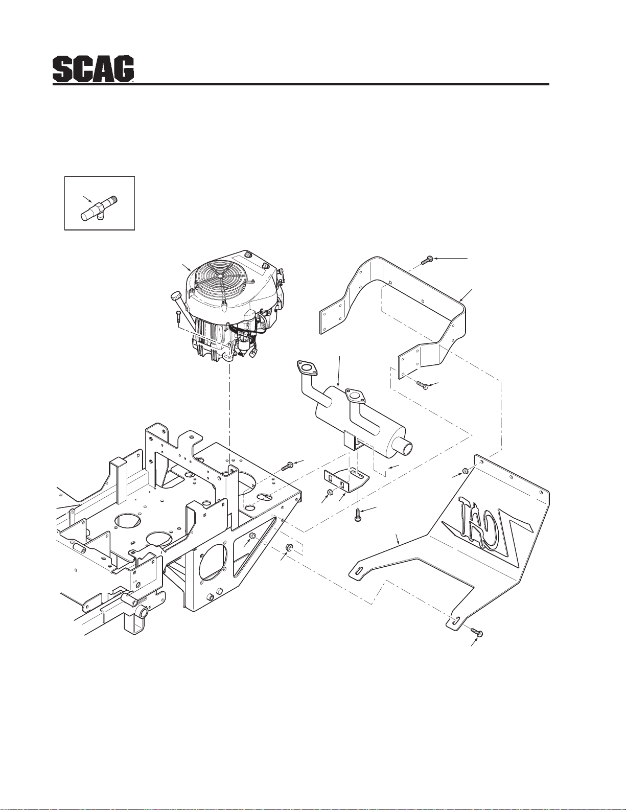
Section 8
A
ENGINE AND ATTACHING PARTS
2
1
6
12
13
13
14
9
8
11
3
4
5
7
48
10
SZC 2005 EAPK
Page 53

Section 8
ENGINE AND ATTACHING PARTS
Ref. Part
No. No. Description
1 483196 Engine, Honda 16hp
482931 Engine, Kawasaki 17hp (FH541V-AS36)
483024 Engine, Kawasaki 19hp (FH580V-AS33)
2 482349 Extension, Oil Drain 4”
3 04104-01 Bolt, Torx 3/8-16 x 1”
4 424014 Bumper, Rear
5 04001-19 Bolt, Hex Head 3/8-16 x 1”
6 483102 Muffler, SZC Kawasaki
483236 Muffler, SZC Honda
7 04019-04 Nut, Serr. Flange 3/8-16
8 04011-12 Bolt, 5/16-18 x 3/4” Self Tap
9 424133 Mounting Bracket, Muffler
10 04104-01 Bolt, Torx 3/8-16 x 1”
11 424072 Skidplate
12 04003-12 Bolt, Carriage 5/16-18 x 3/4”
13 04019-04 Nut, Elastic Stop 3/8-16
14 04019-03 Nut, Elastic Stop 5/16-18
15 04003-12 Bolt, Carriage 5/16-18 x 3/4”
42
49
Page 54
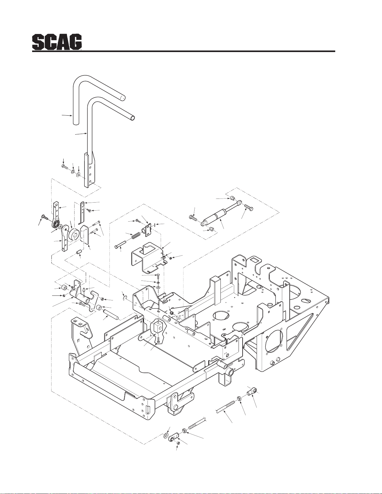
Section 8
STEERING COMPONENTS
1
2
3
4
5
43
44
28
31
27
20
18
18
20
19
11
29
32
6
7
8
26
33
27
12
13
14
24
25
15
23
35
36
16
33
17
21
22
9
45
9
10
28
30
37
38
To Pump
42
41
40
39
34
SZC 2006 SSC
50
Page 55

Section 8
STEERING COMPONENTS
Ref. Part
No. No. Description
1 482340 Grip, Handle Bar
2 461914 Handle Bar, LH (Includes item 1)
461923 Handle Bar, RH (Includes item 1)
3 04001-32 Bolt, Hex Head 3/8-16 x 1-1/4”
4 04030-04 Lock Washer, 3/8”
5 04041-07 Flatwasher, 3/8-.391 x .938 x .105
6 423057 Bracket, Switch Actuator
7 04017-16 Bolt, Hex Serr. Flange 5/16-18 x 3/4”
8 04001-17 Bolt, Hex Head 5/16-18 x 2”
9 483238 Control Lever
10 43559 Spacer, Control
11 423599 Plate, Control Lever
12 43477 Pin Retainer
13 481389 Spring
14 04003-02 Bolt, Carr. 1/4-20 x 3/4”
15 45918 Bracket, Control Return
16 04060-01 Roll Pin, Spring 5/32 x 3/4”
17 461770 Control Bracket with Decal, L.H.
461771 Control Bracket with Decal, R.H.
18 43602 Spacer, Pump Dampener
19 482452 Gas Damper
20 04001-12 Bolt, Hex Head 5/16-18 x 1-3/4”
21 04019-03 Nut, Serr., Flange, 5/16-18
22 04021-08 Nut, Elastic Stop 1/4-20
23 04001-18 Bolt, Hex Head 3/8-16 x 3/4”
24 04030-04 Lock Washer, 3/8”
25 04041-07 Flatwasher, 3/8-.391 x .938 x .105
26 04050-02 Retaining Ring, 3/4” Ext.
27 48100-06 Bushing, .753 ID
28 04021-10 Nut, Elastic Stop 5/16-18
29 48114-04 Grease Fitting, 1/4-28 Self Tap
30 04001-20 Bolt, Hex Head 3/8-16 x 1-1/2”
31 49921 Linkage Bellcrank Assembly R.H.(Incl. Items 27, 29)
49920 Linkage Bellcrank Assembly L.H.(Incl. Items 27, 29)
32 43616 Shaft, Steering Control
33 04021-10 Nut, Elastic Stop 5/16-18
34 482330 Rod End, 3/8-24 RH Female
35 482099 Block, Clamping
36 04001-19 Bolt, Hex Head 3/8-16 x 1”
37 04041-07 Flatwasher, 3/8-.391 x .938 x .105
38 04021-09 Nut, Elastic Stop 3/8-16
39 04020-14 Nut, 3/8-24 RH Thread
40 483133 Link, Pump 3/8-24 x 10.89”
41 04020-17 Nut, 3/8-24 UNF-2B LH Thread
42 482331 Rod End, 3/8-24 LH Thread
43 04003-05 Bolt, Carriage 3/8-16 x 1-1/2”
44 483250 Rubber Spacer
45 483269 Knob
51
Page 56
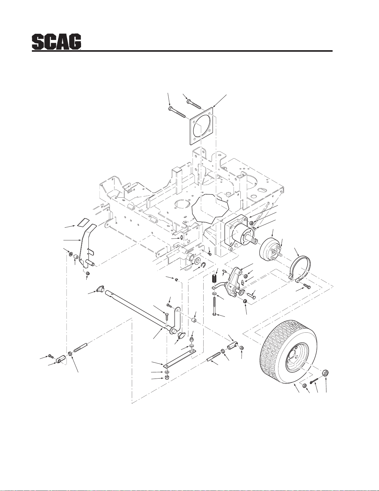
38
29
39
BRAKE COMPONENTS
1
2
13
14
35
Section 8
3, 3A
4
5
6
7
8
34
37
33
36
31
28
30
29
28
34
32
40
34
31
16
29
15
28
33
17
13
27
25
18
19
26
24
41
10
11
4
12
9
20
21
23
22
52
SZC 2005 BSC
Page 57

Section 8
BRAKE COMPONENTS
Ref. Part
No. No. Description
1 04001-163 Bolt, Hex Head 1/2-13 x 3-3/4”
2 04001-52 Bolt, Hex Head 1/2-13 x 2-1/2”
3 483190 Wheel Motor, L.H. - Hydro-Gear
3A 483191 Wheel Motor, R.H. - Hydro-Gear
4 04021-19 Nut, 1/2-13 Center Lock
5 04063-25 Key, Woodruff 5/16 x 1”
6 461438 Wheel Hub Assembly
7 04008-01 Bolt, Serr. Flange 1/2-20 x 1.563”
8 481601 Brake Band Assembly
9 04001-31 Bolt, Hex Head 3/8-16 x 2-1/2”
10 451730 Brake Linkage Weldment, L.H. SZC
451731 Brake Linkage Weldment, R.H. SZC
11 04069-01 Pin, Rue Cotter 3/8 Dia.
12 04064-16 Clevis Pin, 3/8 x 1.93”
13 48114-04 Grease Fitting, 1/4-28
14 04001-08 Bolt, Hex Head 5/16-18 x 3/4”
15 04050-01 Retaining Ring, .625 Ext.
16 04043-06 Flatwasher, 5/8-.688 x 1.75 x .134
17 483124 Spring, Brake
18 04043-04 Flatwasher, 3/8-.391 x .938 x .105 HD
19 04001-77 Bolt, Hex Head 3/8-16 x 3-1/2”
20 48680 Nut, Hex Castle 1.0-20 UNEF
21 04061-06 Cotter Pin, 9/64 x 1-1/2”
22 04028-02 Lug Nut, 1/2-20
23 482185 Wheel Assembly, 23 x 8.5-12 4 Ply (36”)
482186 Rim w/Valve Stem (36”)
481833 Tire, 23 x 8.5-12 4 Ply (36”)
482413 Wheel Assembly, 23 x 9.5-12 4 Ply (42”)
482414 Rim w/Valve Stem (42”)
482194 Tire, 23 x 9.5-12 4 Ply (42”)
24 04021-09 Nut, Elastic Stop 3/8-16
25 483128 Rod End, 3/8-24 R.H. Female
26 04020-25 Nut, 3/8-24 UNF Jam
27 483129 Link, Brake 3/8-24 x 8-5/8”
28 04021-09 Nut, Elastic Stop 3/8-16
29 04043-04 Flatwasher 3/8-.391 x .938 x .105 HD
30 483111 Spring, Flat Brake
31 482061 Bushing, Self Align
32 451733 Brake Shaft Weldment, SZC
33 43063 Spacer
34 04001-21 Bolt, Hex Head 3/8-16 x 1-3/4”
35 423279 Plate Weldment, Motor Backing
36 04020-26 Nut, 3/8-24 UNF L.H. Jam
37 483127 Rod End, 3/8-24 L.H. Female
38 461509 Brake Lever (includes item 39)
39 482102 Grip, Brake Lever
40 04021-10 Nut, Elastic Stop 5/16-18
41 04019-04 Nut, Serr. Flange 3/8-16
53
Page 58
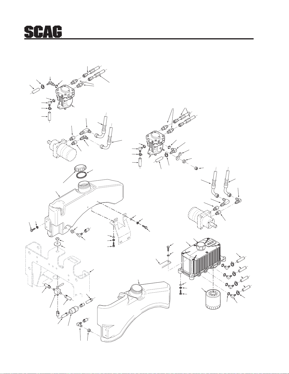
FUEL AND HYDRAULIC SYSTEM
Section 8
33
32
A
B
4
3
3
3
33
4
5
7
A
B
3
5
6
7
8
2
F
K
C
D
6
12
13
D
C
14
3
9
11
3
10
3
7
G
6
5
1
5
6
7
8
E
31
30
1
9
11
10
11
27
28
25
29
28
22
M
29
26
26
M
25
26
25
24
23
34
L
23
22
28
27
FRAME
21
TO
ENGINE
L
27
FRAME
TAB
18
17
16
19
18
17
15
20
11
5
SZC 2005 FHS
8
E
K
8
G
33
33
F
7
6
54
Page 59

Section 8
FUEL AND HYDRAULIC SYSTEM
Ref. Part
No. No. Description
1 483106 Pump, R.H. BDP-10A (PG-1GCC-D11X-XXXX)
2 483105 Pump, L.H. BDP-10A (PG-1JCC-D11X-XXXX)
3 482994 Hose Assembly, Wheel Motor SZC
4 48572-04 Fitting, 1/2” JIC x 1/2” O-Ring
5 48603-06 O-Ring
6 482266-01 Elbow, 90 Degree O-Ring 9/16-18 x 3/8 Hose
7 48136-13 Clamp, Hose .69 Max Dia.
8 48811 Hose, 3/8” Pushlock (order by inch)
9 481761-01 Elbow, 90 Degree JIC to O-Ring
10 48350-02 Elbow, 90 Degree 1/2 x 1/2” JIC to O-Ring
11 48938-02 O-Ring Bushing, 5/8”
12 424061 Control Lever, Pump
13 483123 Retainer, Pump Lever
14 04021-12 Nut, Center Lock 5/16-24
15 483094 Cap, Oil Reservoir
16 461752 Oil Reservoir (incl. items 6, 15, 20)
17 04001-09 Bolt, Hex Head 5/16-18 x 1”
** Available through the individual engine manufacturer.
Ref. Part
No. No. Description
18 04030-03 Lockwasher, 5/16” Spring
19 04040-15 Flatwasher, 5/16-.375 x .875 x .083
20 48462-01 Filter, Spin On
21 461828 Fuel Tank, L.H. SZC
22 48309 Tank Bushing
23 481602 Elbow, 90 Degree
24 ** Fuel Filter
25 48058 Fuel Hose, 1/4 ID
26 482212 Valve, Fuel Shutoff
27 04001-08 Bolt, Hex Head 5/16-18 x 3/4”
28 04030-03 Lockwasher, 5/16
29 04040-15 Flatwasher, 5/16-.375 x .875 x .083
30 461829 Fuel Tank, R.H. SZC
31 482547 Cap, Fuel Tank (incl. item #32)
32 482774 Gasket, Gas Tank Cap
33 483146 Hose, 3/8” Pushlock Gray (order by inch)
34 48059-01 Clamp, Fuel Hose 1/4 Hose ID
55
Page 60
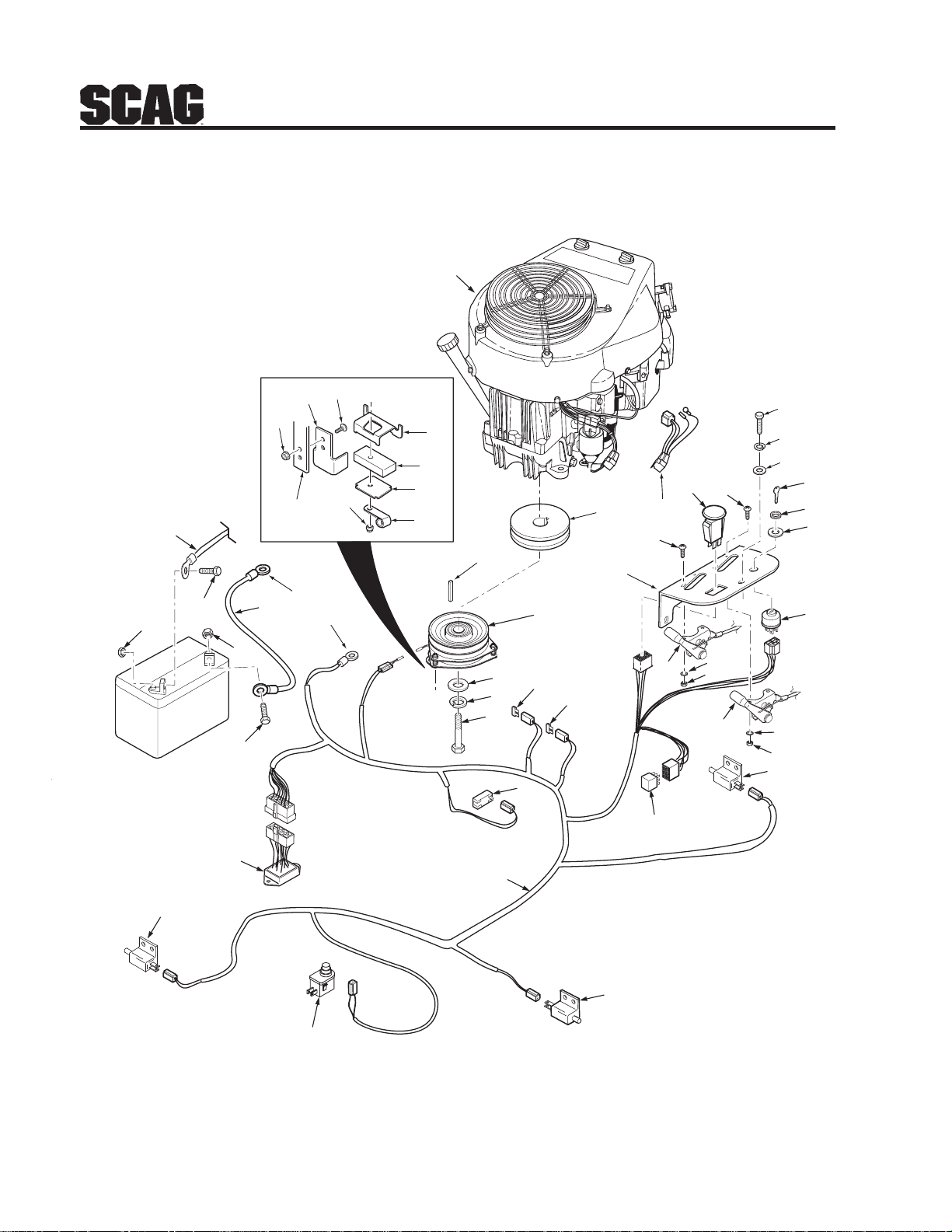
TO STARTER
32
33
FRAME
TAB
ELECTRICAL SYSTEM
1
35
34
A
36
37
38
40
39
19
11
13
12
Section 8
3
4
5
10
2
12
6
7
8
30
17
29
RIGHT
HANDLE
28
29
30
31
ENGINE
MOUNT
SEAT
27
20
21
24
A
22
23
25
26
LEFT
HANDLE
24
17
15
18
9
16
15
BRAKE
14
9
16
17
56
SZC 2005 ESKA
Page 61

Section 8
Ref. Part
No. No. Description
1 483196 Engine, Honda 16hp
482931 Engine, Kawasaki 17hp (FH541V-AS36)
483024 Engine, Kawasaki 19hp (FH580V-AS33)
2 483103 Wire Harness Adapter, SZC Kawasaki
483103 Wire Harness Adapter, SZC Honda
3 04001-08 Bolt, Hex Head 5/16-18 x 3/4”
4 04030-03 Lockwasher, 5/16
5 04040-15 Flatwasher, 5/16-.375 x .875 x .083
6 48017-02 Key, Ignition
7 48017-04 Nut, Hex 5/8-32
8 48017-03 Lockwasher, 5/8” Internal
9 04031-01 Lock Washer, #10 External Tooth
10 483162 Switch, PTO
11 482968 Pulley, 5.45” Dia. 1” Bore
12 04010-12 Screw, #10-32 x 3/4”
13 461836 Instrument Panel
14 48798 Switch, Ignition
15 483168 Control Cable
16 04020-01 Nut, Hex #10-32
17 481637 Switch, N/O
18 483013 Relay
19 04063-23 Key, 1/4 x 1/4 x 3-1/4”
20 461772 Clutch Assembly, GT2.5 - 1” Bore (incl. items 33, 34, 35, 36, 37, 38, 39, 40)
21 04041-28 Flatwasher, 7/16-.469 x 1.75 x .25
22 04030-05 Lockwasher, 7/16 Spring
23 04102-04 Bolt, Hex Head 7/16-20 x 2-1/2” w/Patch
24 48298 Fuse, 20 amp
25 483072 Hourmeter
26 483020 Wire Harness, SZC
27 481638 Switch, Seat
28 483029 Electric Module
29 04001-44 Bolt, Hex Head 1/4-20 x .5”
30 04020-02 Nut, Hex 1/4-20
31 48029-15 Battery Cable, Negative Black
32 48029-12 Battery Cable, Positive Red
33 04021-10 Nut, Elastic Stop 5/16-18
34 421370 Plate, Clutch Anti-Rotation
35 04003-04 Bolt, Carriage 5/16-18 x 1”
36 422533 Retainer, Clutch
37 481716 Rubber Pad, Clutch Stop
38 422534 Plate, Backing
39 48030-09 Clamp, Cable 1/2” ID
40 04021-10 Nut, Elastic Stop 5/16-18
ELECTRICAL SYSTEM
57
Page 62
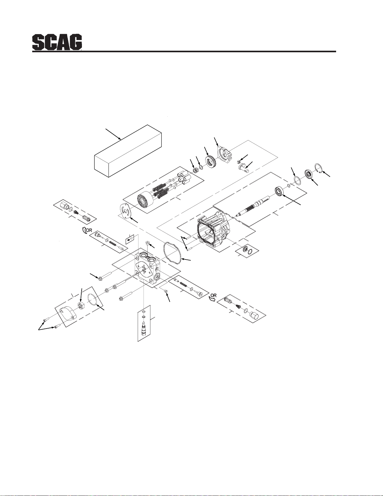
HYDRAULIC PUMP ASSEMBLY
29
Overhaul Seal Kit
17
18
Section 8
20
21
23
22
15
14
13
16
30
PORT "A"
SIDE
6
9
24
4
7
8
25
19
27
10
3
1
5
2
24
28
PORT "B"
SIDE
26
30
11
12
58
Page 63

Section 8
Ref. Part
No. No. Description
1 HG 70516 Housing Kit
2 HG 70573 End Cap Kit
3 HG 50641 Straight Headless Pin
4 HG 50969 Hex Flange Bolt, M8-1.25 x 60mm
5 HG 51232 Housing O-Ring
6 HG 2513027 Charge Pump Kit
7 HG 50273 Gerotor Assembly
8 HG 9004101-1340 O-Ring
9 HG 50095 Socket Head Screw, M6 x 1.0-20mm
10 HG 2513030 Bypass Valve Kit
11 HG 70521 Pumpshaft Kit
12 HG 50315 Ball Bearing, 17 x 40 x 12
13 HG 51161 Lip Seal
14 HG 50329 Retaining Ring
15 HG 50951 Spacer
16 HG 70331 Cylinder Block Kit
17 HG 2003014 Block Spring
18 HG 2003017 Block Thrust Washer
19 HG 51444 Valve Plate
20 HG 2003087 Swash Plate
21 HG 50551 Ball Thrust Bearing
22 HG 50807 Trunnion Arm
23 HG 2000015 Slot Guide
24 HG 2510062 Check Valve Kit (.024” Orfice) port “A” on Left Hand Pump, port “B” on Right Hand Pump
25 HG 70403 Charge Relief Kit
26 HG 2513043 Trunnion Seal with Retainer
27 HG 9005110-4400 Straight Thread Plug
28 HG 9005110-3100 Straight Thread Plug
29 HG 70525 Overhaul Seal Kit
30 HG 70589 System Check Relief Kit, port “B” on Left Hand Pump, port “A” on Right Hand Pump
HYDRAULIC PUMP ASSEMBLY
59
Page 64
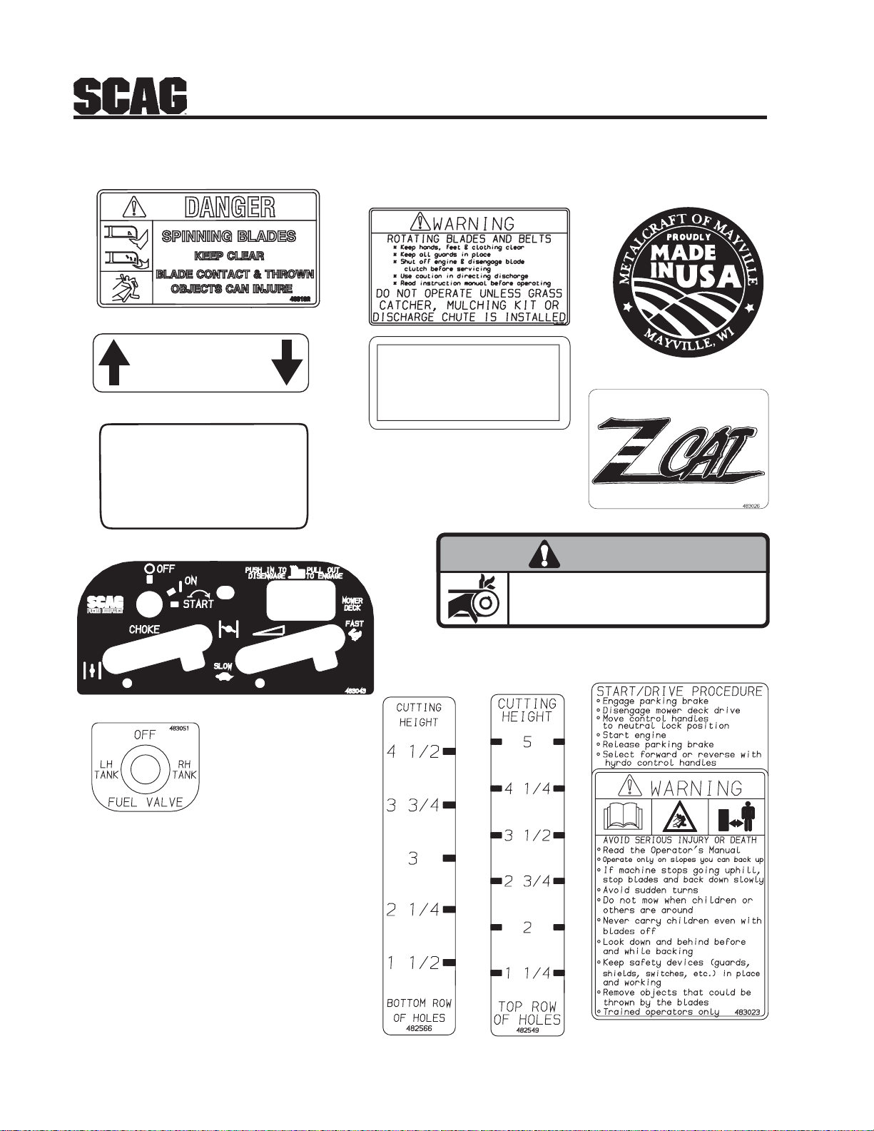
REPLACEMENT DECALS AND INFORMATION PLATES
12
FORWARD
F
R
REVERSE
482100
6
MANUFACTURED UNDER ONE OR MORE
OF THE FOLLOWING PATENTS:
4,487,006 4,885,903 4,920,733 4,967,543
4,991,382 4,998,948 5,042,239 5,118,617
5,133,176 5,826,416 5,832,708 5,865,018
6,192,666 6,766,633 6,892,519
PATENTS PENDING
5
Section 8
48404
8
Hea
vy-
Duty
Co mmerc
11
ial
481971
13
7
WARNING
INSTALL BELT COVER BEFORE
OPERATING MACHINE
READ OPERATOR'S MANUAL
10
481039
9
60
12
18
4
SZC 2005 RDP1
Page 65
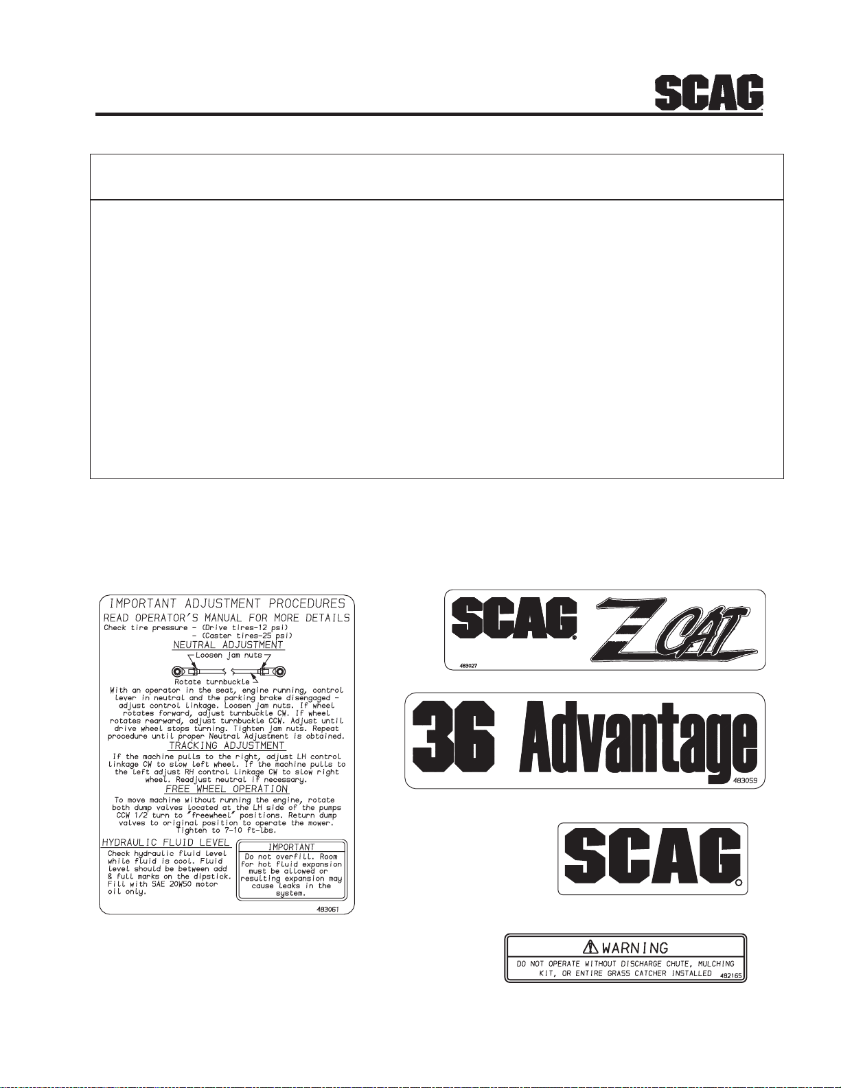
Section 8
REPLACEMENT DECALS AND INFORMATION PLATES
Ref. Part
No. No. Description
1 483206 Decal, Danger-Spinning Blades
2 482286 Decal, Warning-Rotating Blades
3 483059 Decal, 36 Advantage
483060 Decal, 42 Advantage
4 483023 Decal, Fuel Tank Start/Drive
5 483044 Decal, Patents
6 482100 Decal, Traction Control
7 481971 Decal, Heavy Duty Commercial
8 48404 Decal, Metalcraft - Made in USA
9 481039 Decal, Belt Cover
10 483163 Decal, Instrument Panel
11 483051 Decal, Fuel Shutoff
12 482566 Decal, Cutting Height Bottom Row of Holes
13 483026 Decal, Front SZC
14 483061 Decal, Seat Support
15 483027 Decal, Rear SZC
16 482166 Decal, Front Footplate
17 482165 Decal, Discharge Chute
18 482549 Decal, Cutting Height Top Row of Holes
14
61
R
482166
SZC 2005 RDP2
15
3
16
17
Page 66
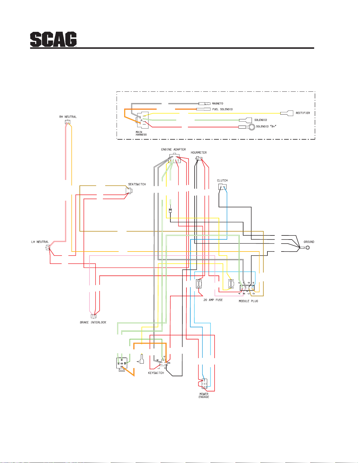
ELECTRICAL SCHEMATIC
ADAPTER HARNESS
WHITE
RED W/YEL STRIPE
YELLOW
GRN W/WHT STRIPE
RED
Section 8
BROWN
WHITE
ORANGE
RED W/WHITE STRIPE
RED
RED
RED
RED
BROWN
ORANGE
RED
RED
PINK
GRN W/WHT STRIPE
GRN W/WHT STRIPE
GREEN
RED W/YEL STRIPE
WHITE
YELLOW
GRN W/WHT STRIPE
GRN W/WHT STRIPE
WHITE
RED
YELLOW
RED
RED
RED
RED
RED
BLUE
BLACK
BLACK
BLACK
LIGHT BLUE
RED
BLUE
RED
RED
LIGHT BLUE
BLACK
BLACK
BLACK
BLACK
BROWN
RED
PINK
RED
ORANGE
62
RED
SZC Electrical Schematic
Page 67

LIMITED WARRANTY - COMMERCIAL EQUIPMENT
Any part of the Scag commercial mower manufactured by Scag Power Equipment and found, in the reasonable judgment
of Scag, to be defective in materials or workmanship, will be repaired or replaced by an Authorized Scag Service Dealer
without charge for parts and labor during the periods specified below . This warranty is limited to the original purchaser
and is not transferable. Proof of purchase will be required by the dealer to substantiate any warranty claims. All warranty
work must be performed by an Authorized Scag Service Dealer .
This warranty is limited to the following specified periods from the date of the original retail purchase for defects in
materials or workmanship:
* Wear items including drive belts, blades, hydraulic hoses and tires are warranted for ninety (90) days.
* Batteries are covered for ninety (90) days.
* Frame and structural components including oil reservoir and oil coolers are warranted for 2 years (Parts and
labor).
* Cutter decks are warranted against cracking for a period of three (3) years. (Parts and labor 1st and 2nd year;
Parts only 3rd year) The repair or replacement of the cutter deck will be at the option of Scag Power
Equipment. We reserve the right to request components for evaluation. This warranty does not cover any
mower that has been subject to misuse, neglect, negligence, accident, or that has been operated in any way
contrary to the operating instructions as specified in the Operator’s Manual.
* Engines and electric starters are covered by the engine manufacturer’s warranty period.
* Major drive system components are warranted for two (2) years by Scag Power Equipment. (Parts and labor)
(T wo year warranty exclude fittings, hoses, drive belts). The repair or replacement of the hydraulic pump or
hydraulic motor will be at the option of Scag Power Equipment. This warranty does not cover any mower that
has been subject to misuse, neglect, negligence, or accident, or that has been operated in any way contrary to
the operating instructions as specified in the Operator’s Manual.
* Electric clutches have a Limited W arranty for 2 year (Parts and labor).
* Cutter Spindle Assemblies have a Limited Warranty for three years (Parts and labor 1st year and 2nd;
Parts only 3rd year).
* Any Scag product used for rental purposes is covered by a 90 day warranty.
The Scag mower, including any defective part must be returned to an Authorized Scag Service Dealer within the warranty
period. The expense of delivering the mower to the dealer for warranty work and the expense of returning it to the owner
after repair will be paid for by the owner. Scag’ s responsibility is limited to making the required repairs and no claim of
breach of warranty shall be cause for cancellation or rescission of the contract of sale of any Scag mower.
This warranty does not cover any mower that has been subject to misuse, neglect, negligence, accident, or that has been
operated in any way contrary to the operating instructions as specified in the Operator’s Manual. The warranty does not
apply to any damage to the mower that is the result of improper maintenance, or to any mower or parts that have not been
assembled or installed as specified in the Operator’s Manual and Assembly Manual. The warranty does not cover any
mower that has been altered or modified, changing performance or durability. In addition, the warranty does not extend to
repairs made necessary by normal wear, or by the use of parts or accessories which, in the reasonable judgment of Scag,
are either incompatible with the Scag mower or adversely affect its operation, performance or durability .
Scag Power Equipment reserves the right to change or improve the design of any mower without assuming any obligation to modify any mower previously manufactured. All other implied warranties are limited in duration to the two (2) year
warranty period or ninety (90) days for mowers used for rental purpose. Accordingly, any such implied warranties
including merchantability, fitness for a particular purpose, or otherwise, are disclaimed in their entirety after the expiration
of the appropriate two year or ninety day warranty period. Scag’s obligation under this warranty is strictly and exclusively
limited to the repair or replacement of defective parts and Scag does not assume or authorize anyone to assume for them
any other obligation. Some states do not allow limitations on how long an implied warranty lasts, so the above limitation
may not apply to you.
Scag assumes no responsibility for incidental, consequential or other damages including, but not limited to, expense for
gasoline, expense of delivering the mower to an Authorized Scag Service Dealer and expense of returning it to the owner ,
mechanic’s travel time, telephone or telegram char ges, rental of a like product during the time warranty repairs are being
performed, travel, loss or damage to personal property, loss of revenue, loss of use of the mower, loss of time or inconvenience. Some states do not allow the exclusion or limitation of incidental or consequential damages, so the above limitation or exclusion may not apply to you. This warranty gives you specific legal rights, and you may also have other rights
which vary from state to state.
Page 68

GARANTÍA LIMIT ADA - EQUIPO COMERCIAL
Toda pieza del cortacésped comercial Scag fabricada por Scag Power Equipment que, según criterio razonable de Scag, presente
materiales o mano de obra defectuosos será reparada o reemplazada por un distribuidor autorizado Scag sin cargo por las piezas ni
mano de obra durante los períodos especificados abajo. Esta garantía se limita al comprador original y no es transferible. Para acceder a
cualquier reclamo de garantía, el distribuidor requerirá el comprobante de compra. T odo trabajo bajo garantía debe realizarlo un
distribuidor autorizado Scag.
Con respecto a materiales o mano de obra defectuosos, esta garantía se limita a los siguientes períodos especificados a partir de la fecha
de compra original:
* Los artículos desgastables, incluyendo correas de transmisión, cuchillas, mangueras hidráulicas y llantas, están garantizados
por noventa (90) días.
* Las baterías están garantizadas por noventa (90) días.
* El bastidor y los componentes estructurales, incluyendo el depósito de aceite y los enfriadores de aceite, tienen una garantía
de 2 años (Piezas y mano de obra).
* Las plataformas de corte están garantizadas contra grietas por un período de tres (3) años. (Piezas y mano de obra, primer y
segundo año; piezas solamente, tercer año). La reparación o el reemplazo de la plataforma de corte estarán sujetos a
discreción de Scag Power Equipment. Nos reservamos el derecho de solicitar componentes para su evaluación. Esta garantía
no cubre ningún cortacésped que haya sido sometido a uso indebido, descuido, negligencia o accidente, o que se haya operado
de manera distinta a la especificada en el manual del operador.
* Los motores eléctricos y los arrancadores están cubiertos por el período de garantía del fabricante del motor.
* Los componentes principales del sistema de transmisión están garantizados por Scag Power Equipment por dos (2) años.
(Piezas y mano de obra) (La garantía de dos años no incluye las conexiones, mangueras, correas de transmisión). La
reparación o el reemplazo de la bomba hidráulica o el motor hidráulico estarán sujetos a discreción de Scag Power Equipment.
Esta garantía no cubre ningún cortacésped que haya sido sometido a uso indebido, descuido, negligencia o accidente, o que se
haya operado de manera distinta a la especificada en el manual del operador.
* Los embragues eléctricos tienen una Garantía limitada de 2 años (Piezas y mano de obra).
* Los ensambles del eje tienen una Garantía limitada de 3 años (Piezas y mano de obra, primer y segundo año; piezas
solamente, tercer año).
* Cualquier producto Scag que se utilice para alquiler está cubierto por una garantía de 90 días.
El cortacésped Scag, incluida cualquier pieza defectuosa, debe ser llevado a un distribuidor autorizado de Scag dentro del período de
garantía. Los gastos incurridos en la entrega del cortacésped al distribuidor para que se realice el trabajo bajo garantía, así como los
gastos de devolución del cortacésped al propietario después de la reparación, estarán a cargo del propietario. La responsabilidad de Scag
se limita a la realización de las reparaciones requeridas y ninguna reclamación por incumplimiento de las obligaciones de garantía será
causa de cancelación o revocación del contrato de venta del cortacésped Scag.
Esta garantía no cubre ningún cortacésped que haya sido sometido a uso indebido, descuido, negligencia o accidente, o que se haya
operado de manera distinta a la especificada en el manual del operador. La garantía no será de aplicación en ningún caso de daño
ocasionado al cortacésped como consecuencia de mantenimiento inadecuado o a cualquier cortacésped o piezas que no se hayan
ensamblado o instalado de acuerdo con las especificaciones del manual del operador o el manual de montaje. La garantía no cubre ningún
cortacésped que haya sufrido alteraciones o modificaciones que hayan afectado su funcionamiento o durabilidad. Asimismo, la garantía
no se extiende a reparaciones necesarias por el desgaste normal o por el uso de piezas o accesorios que, según criterio razonable de Scag,
sean incompatibles con el cortacésped Scag o afecten la operación, funcionamiento o durabilidad de éste.
Scag Power Equipment se reserva el derecho de modificar o mejorar el diseño de cualquier cortacésped sin tener por ello
obligación alguna de modificar cualquier cortacésped fabricado con anterioridad. Cualquier otra garantía implícita se limita a un
período de garantía de dos (2) años o noventa (90) días en el caso de cortacéspedes destinados a alquiler. Por consiguiente, se rechaza en
su totalidad cualquier garantía implícita, incluidas las garantías de comerciabilidad, adecuación para un fin determinado, o de otro tipo,
después de la finalización del correspondiente período de garantía de dos años o noventa días. La obligación de Scag en virtud de la
presente garantía se limita estricta y exclusivamente a la reparación o el reemplazo de piezas defectuosas, y Scag no asume ni autoriza a
ningún otro a asumir en su lugar ninguna otra obligación. La limitación antes mencionada no será de aplicación en aquellos estados en los
que no esté permitida la limitación del período de validez de una garantía implícita.
Scag no asume responsabilidad alguna por daños incidentales, consecuentes ni de cualquier otro tipo, incluyendo, pero sin limitarse a,
gasto de gasolina, gasto de entrega del cortacésped a un distribuidor autorizado Scag y gasto de su devolución al propietario, tiempo de
viaje del mecánico, cargos por comunicaciones telefónicas o telegramas, alquiler de un producto similar durante el período en que se
llevan a cabo las reparaciones bajo garantía, viajes, pérdida o daño de bienes personales, lucro cesante, daños ocasionados por la pérdida
del uso del cortacésped, daños por la pérdida de tiempo o cualquier otro inconveniente. La limitación o exclusión antes mencionada no
será de aplicación en aquellos estados en los que no esté permitida la exclusión o limitación de daños incidentales o consecuentes, así
que la limitación o exclusión ya mencionadas pueden no aplicarse a su caso. La presente garantía le otorga derechos legales específicos,
aparte de los derechos de los que usted goza, según el estado.
Page 69
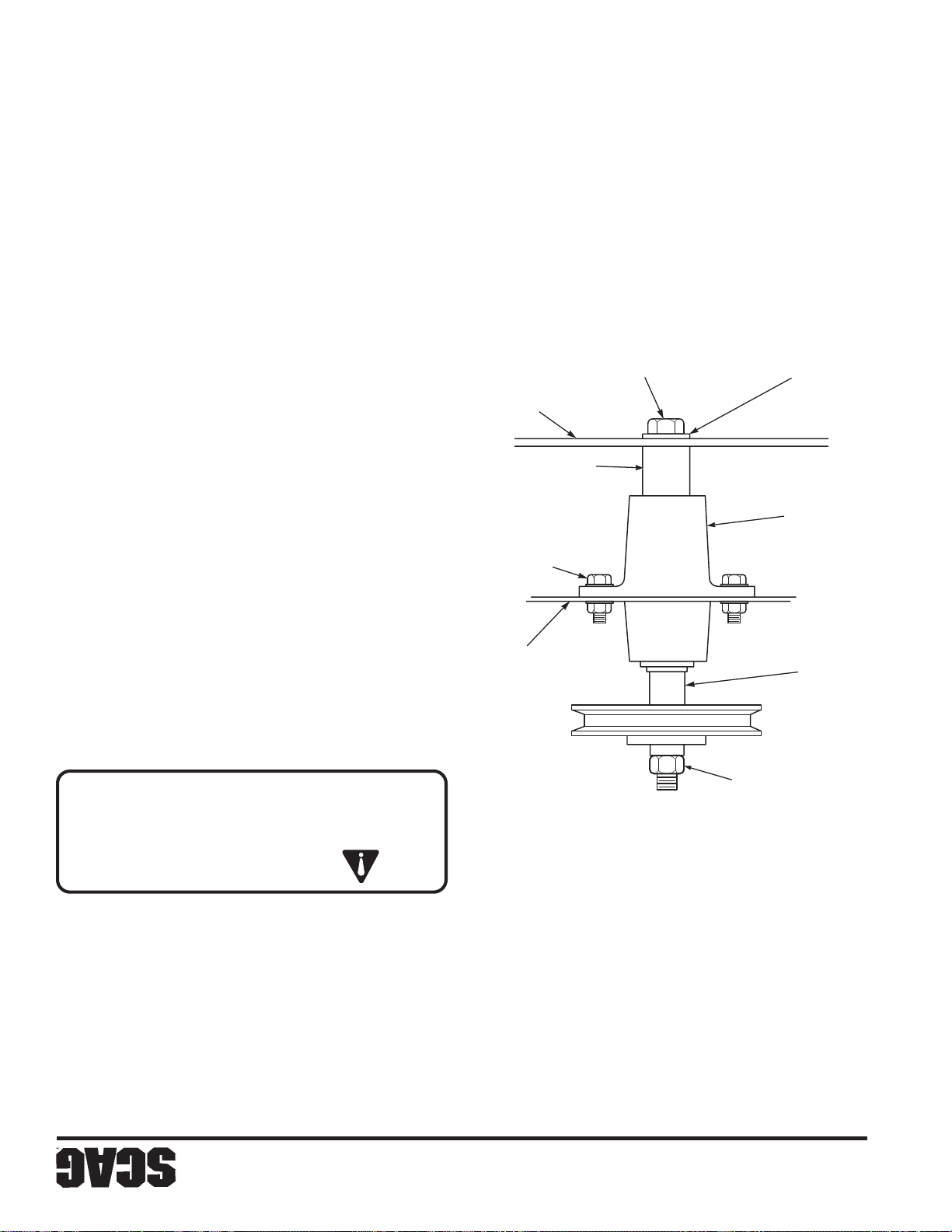
37
P
7-10).
las cuchillas con un apriete de 75 lbs-pie. (V ea la Figura
en la parte superior del eje de corte. Evite el giro de
6. Instale la tuerca hexagonal en el perno de la cuchilla
introduzca el perno en el eje de corte.
5. Instale el espaciador en el perno de la cuchilla e
de corte.
izamiento hacia la parte superior de la plataforma
Asegúrese que la cuchilla se instale con la aleta de
-NOTA-
Figura 7-10 Reemplazo de la cuchilla
390S0160 S
DE CORTE
CUCHILLA
de la pintura.
con una cera automotriz para una máxima protección
CUCHILLA DE CORTE
ESPACIADOR DE
PERNO HEXAGONAL
distribuidor autorizado Scag. Encere el cortacésped
de retoque Scag (N/P 48521) disponible en su
ARANDELA
DEL EJE
CONJUNTO
4. Repare las superficies de metal dañadas con la pintura
CABEZA HEXAGONAL
PERNO / TUERCA DE
vinilo/caucho para limpiar el asiento.
3. Use una solución suave de jabón o un limpiador de
2. No rocíe los componentes eléctricos.
DE CORTE
PLATAFORMA
EJE
automotrices. No use limpiadores a presión.
plataforma de corte. Use agua fría y limpiadores
1. Después que cada uso, lave el cortacésped y la
HEXAGONAL 75 LB-PIE
comprimido.
está caliente. No lave el motor; use aire
No lave ninguna parte del equipo mientras
PRECAUCIÓN:
TORQUE DE TUERCA
perno en el agujero de la cuchilla.
arandela plana en el perno de la cuchilla y deslice el
4. Para instalar la nueva cuchilla de corte, coloque la
7.11 CUERPO, PLATAFORMA Y TAPICERÍA
-NOTA-
Ruedas motrices ............................. 12 PSI
Ruedas locas .................................. Llantas macizas
horas de operación o diariamente.
Verifique las presiones de las llantas después de cada 8
7.10 LLANTAS
de la máquina.
tendrá que levantarse ligeramente la parte frontal
Para quitar el perno de la cuchilla del eje de corte
(Figura 7-10).
cuchilla de corte, el perno y el espaciador del eje.
la tuerca del perno de fijación de la cuchilla. Quite la
para ayudarlo a asegurar las cuchillas de corte) y quite
(Use la herramienta opcional Blade Buddy , N/P 9212,
3. Asegure las cuchillas de corte para evitar que giren,
Sección 7
Page 70
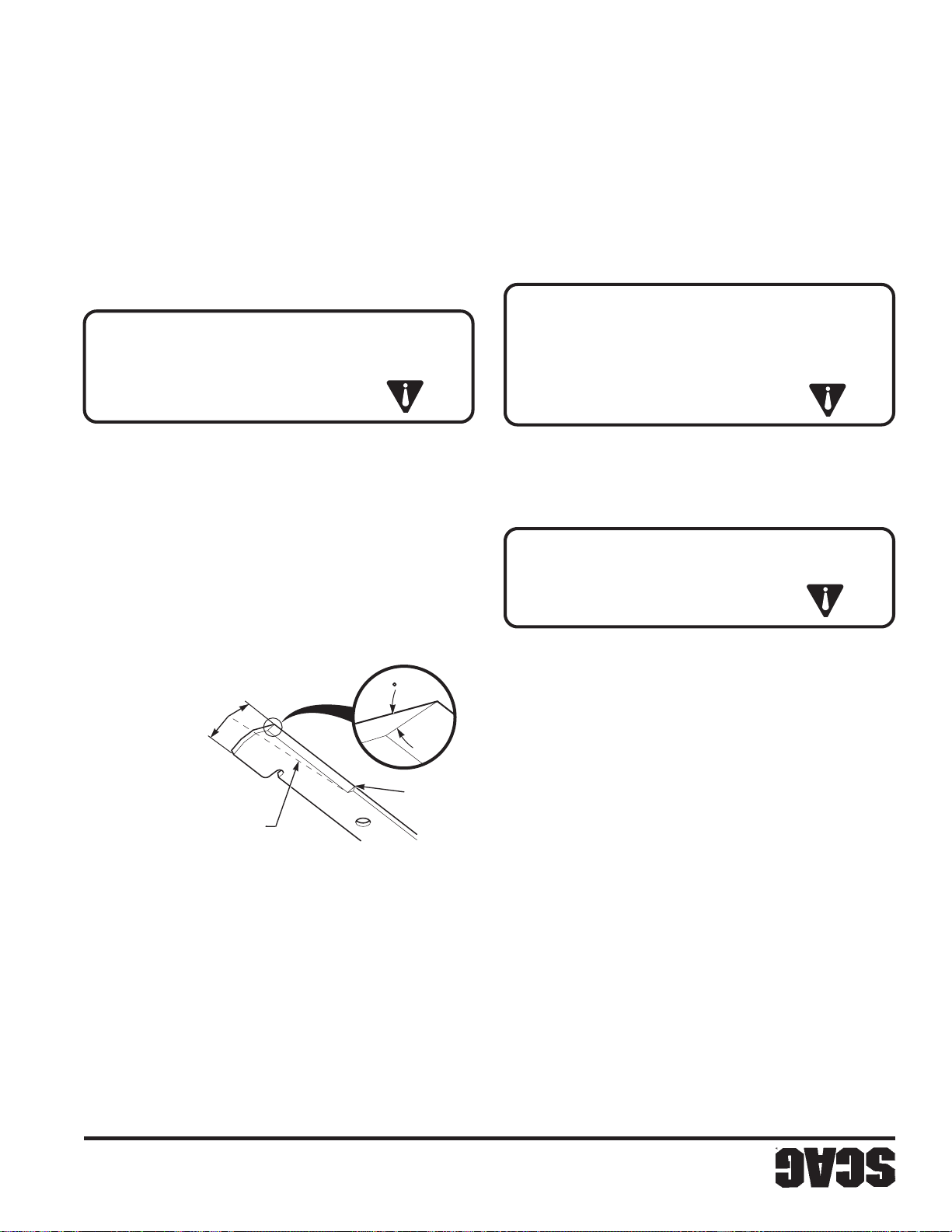
ADVERTENCIA:
36
de altura de corte para evitar que caiga la plataforma.
alta. Coloque el pin de amarre en la posición más alta
2. Levante la plataforma del cortacésped a la posición más
cuchillas.
1. Quite la llave de encendido antes de reemplazar las
manos y ojos al trabajar con cuchillas de corte.
Siempre lleve la protección apropiada para
-NOTA-
motor y del eje de la cuchilla.
del cortacésped y causa un desgaste adicional del
de césped, sino que disminuye la velocidad de corte
cuchillas desafiladas no sólo produce un mal corte
Mantenga afiladas las cuchillas. Cortar con
afilarlas. Vea “Reemplazo de la cuchilla”.
tiene muescas, debe afilarse. Quite las cuchillas para
4. Si el borde de corte de una cuchilla está desafilado o
para garantizar seguridad.
Siempre reemplácela con una cuchilla nueva
nunca suelde una cuchilla rota o rajada.
No trate de enderezar una cuchilla doblada, y
ADVERTENCIA:
C. Reemplazo de la cuchilla
cuchillas usted mismo.
herramientas especiales si prefiere balancear sus
autorizado Scag para balancear la cuchilla o por
desgaste prematuro. Consulte con su distribuidor
están desbalanceadas, puede producirse vibración y
2. Revise el balance de la cuchilla. Si las cuchillas
Figura 7-9 Afilado de la cuchilla
SGB033 SP
del ancho de la cuchilla
X NO debe exceder 1/3
X
30
ADVERTENCIA:
ser reemplazadas.
cuchillas de corte parecen estar dobladas, tendrán que
3. V erifique que las cuchillas de corte estén rectas. Si las
manos y ojos al trabajar con cuchillas de corte.
Siempre lleve la protección apropiada para
de altura de corte para evitar que caiga la plataforma.
alta. Coloque el pin de amarre en la posición más alta
2. Levante la plataforma del cortacésped a la posición más
cuchillas.
1. Quite la llave de encendido antes de dar servicio a las
A. Inspección de la cuchilla
No corte
la cuchilla
Mantenga el ángulo de
borde de corte para mantener el filo.
(Vea la Figura 7-9). Sólo afile la parte superior del
1. Afile el borde de corte en el mismo bisel que el original
-NOTA-
cuchilla.
NO afile las cuchillas más de 1/3 del ancho de la
-NOTA-
Si usa una esmeriladora, puede quemar la cuchilla.
Si es posible, use una lima para afilar la cuchilla.
-NOTA-
7.9 CUCHILLAS DE CORTE
Scag para el ajuste de la correa.
correas, consulte con su distribuidor autorizado
Si experimenta un frecuente desgaste o rotura de
o semanalmente, lo que ocurra primero.
verifique las correas después de cada 40 horas de operación
su correcta alineación y revisar su desgaste. Después,
primeras 2, 4, 8 y 10 horas de operación, debe verificarse
resortes y son auto tensionantes, pero después de las
Todas las correas de transmisión están cargadas por
Sección 7
B. Afiliado de las cuchillas
7.8 CORREAS DE TRANSMISIÓN
Page 71
ADVERTENCIA:
35
negativo al poste negativo de la batería.
positivo al poste positivo de la batería, y luego el cable
2. Cuando conecte los cables del puente, conecte el cable
tener un sistema de tierra negativo.
Si se usa un vehículo para el arranque por puente, debe
1. La batería auxiliar de arranque debe ser de 12 voltios.
B. Arranque por puente
para permitir el enfriamiento.
la tasa de carga debe reducirse o detenerse temporalmente
producción de gas, o si la temperatura excede 52°C (125°F),
125º F). Si se produce derrame de electrolito o excesiva
electrolito o si la batería no está muy caliente (encima de
si no provocan excesivos gases, si no arrojan demasiado
Las tasas de carga entre 3 y 50 amperios son satisfactorias
los gases producidos durante la carga.
bien ventilado de modo que se puede disipar
EXPLOSIVOS. Cargue la batería en un espacio
LAS BATERÍAS PRODUCEN GASES
líquidos que induzcan al vómito.
de contacto interno, NO PROPORCIONE
atención médica inmediatamente. En caso
huevos batidos, o aceite vegetal. Obtenga
agua. Continúe con leche de magnesia,
INTERNO — Beba grandes cantidades de
médica inmediatamente.
durante 15 minutos y obtenga atención
OJOS — Enjuague con agua al menos
las placas en todas las celdas.
antes de cargarla y asegúrese de que el electrolito cubre
Siempre que sea posible, quite la batería del cortacésped
de conectar un cargador.
causar lesiones. Permita que la batería se entibie antes
NO cargue una batería congelada. Puede estallar y
de baterías.
capaz de recargar la batería, y se necesitará un cargador
período largo de tiempo, el alternador puede no ser
Si la batería se ha descargado completamente por un
tendrá problemas para mantener la carga de la batería
Bajo condiciones normales el alternador del motor no
instrucciones específicas.
Consulte el manual del cargador de batería para
DE BATERÍA
ADVERTENCIA:
A. Carga de la batería
agua.
CONTACTO EXTERNO — Enjuague con
PRIMEROS AUXILIOS PARA ELECTROLITO
las sugerencias de primeros auxilios.
ocurre contacto con el líquido, siga primero
batería más de 45° en ninguna dirección. Si
manipule baterías. NO INCLINE ninguna
Use equipo de protección apropiado cuando
del líquido con los ojos, la piel, o con la ropa.
QUEMADURAS QUÍMICAS. Evite el contacto
que es TÓXICO y puede causar GRAVES
El líquido de la batería contiene ácido sulfúrico
Sección 7
Page 72
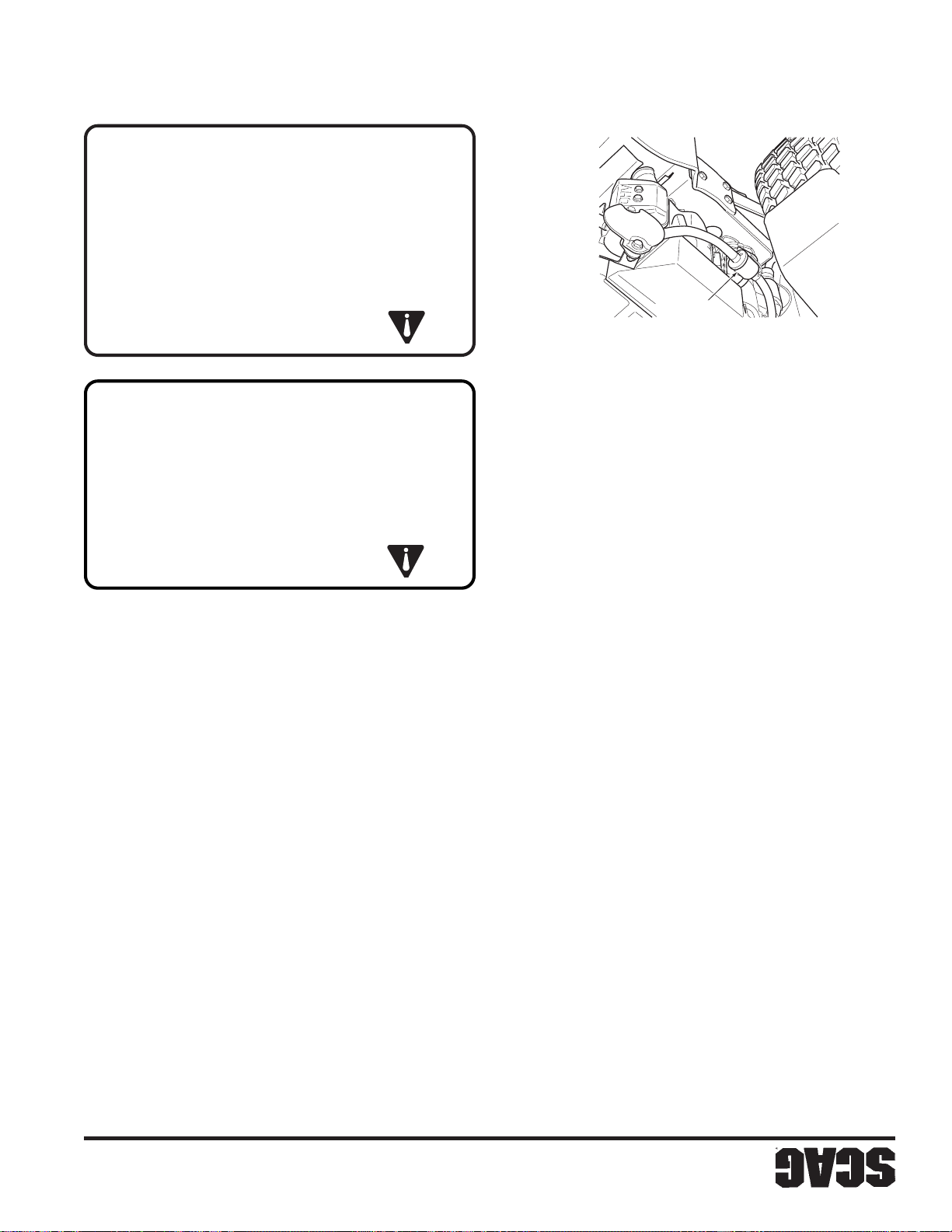
ADVERTENCIA:
34
del motor
SZC 2005 EFF SP
y use gafas de seguridad.
baterías. Proporcione ventilación apropiada
arcos, las chispas y las llamas lejos de las
humo cerca de las baterías. Mantenga los
baterías, NO USE materiales que produzcan
personales al revisar, probar o cargar
inflamables y explosivos. Para evitar lesiones
Las baterías plomo-ácido producen gases
COMBUSTIBLE
FILTRO DE
Figura 7-6 Ubicación del filtro de combustible
firmemente.
10. Coloque nuevamente la tapa de gasolina y apriete
manipular baterías.
reproductivos. Lávese las manos después de
causantes de cáncer y daño a los órganos
identifica a estas sustancias químicas como
compuestos de plomo; el Estado de California
accesorios relacionados contienen plomo y
Los postes de la batería, los terminales y los
cambiársela inmediatamente y lavar la piel afectada.
9. Si se derrama combustible en la ropa, debe
posición abierta.
No utilice un dispositivo que bloquee la boquilla en
recipiente hasta terminar de llenar el combustible.
tanque de combustible o con la abertura del
8. Mantenga la boquilla en contacto con el borde del
ADVERTENCIA:
dispensador de gasolina.
portátil en lugar de usar una boquilla de un
7.7 BATERÍA
espuma como recomienda el fabricante del motor.
3. Limpie o reemplace el filtro de aire y el pre-filtro de
2 Quite el filtro de aire e inspecciónelo.
Déjela a un costado.
filtro de aire al conjunto del filtro y retire la cubierta.
1. Libere los dos seguros que aseguran la cubierta del
al día para prevenir daños al motor.
necesario verificar el elemento una o dos veces
En condiciones de mucho polvo, puede ser
-NOTA-
primero, y reemplace el elemento si es necesario.
horas de operación o cada dos semanas, lo que ocurra
Inspeccione y limpie el filtro de aire después de cada 100
determina los períodos de servicio del filtro de aire.
Para cualquier filtro de aire, el ambiente de operación
es posible, añada el combustible con un recipiente
abastézcala de combustible en el terreno. Si esto no
7. Retire la máquina del camión o del remolque y
combustible.
terreno lejos de su vehículo antes de abastecerlos de
plástico. Siempre coloque los recipientes en el
un camión o remolque que tenga forro de material
6. Nunca llene recipientes dentro de un vehículo ni en
aparatos.
luz piloto, como de un calentador de agua u otros
combustible donde haya una llama abierta, chispa o
5. Nunca almacene el cortacésped o el recipiente de
techo ni en un remolque cerrado.
4. Nunca abastezca de combustible al cortacésped bajo
combustible.
que el motor se enfríe antes de abastecerlo de
combustible con el motor en funcionamiento. Permita
3. Nunca retire la tapa de la gasolina ni agregue
Sección 7
filtro de aire
A. Limpieza y/o reemplazo del elemento del
7.6 FILTRO DE AIRE DEL MOTOR
2. Use solamente un recipiente aprobado para gasolina.
fuentes de ignición.
1. Apague todos los cigarrillos, puros, pipas y otras
Page 73
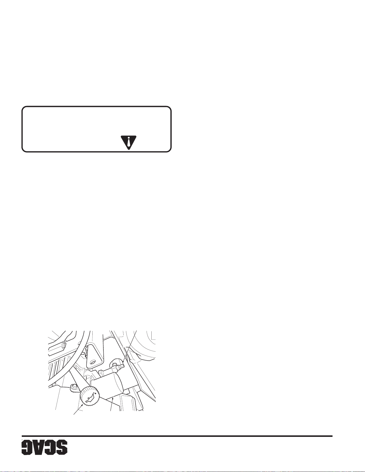
33
extremadamente inflamable y los vapores son explosivos.
tenga mucho cuidado al manipular gasolina. La gasolina es
Para evitar lesiones personales o daños a la propiedad,
reciente y sin plomo, con un octanaje mínimo de 87.
rellenador. No llene demasiado. Use gasolina limpia,
operación hasta 1 pulgada debajo del cuello del
Llene el tanque de combustible al inicio de cada día de
A. Llenado del tanque de combustible
cortacésped para instrucciones.
manual del operador del motor proporcionado con este
tanque de combustible y rellenar.
cortacésped se enfríe antes de quitar la tapa del
Para evitar quemaduras, permita que el
PELIGRO:
o cada dos semanas, lo que ocurra primero. Consulte el
cambie el aceite después de cada 100 horas de operación
aceite del cárter y reemplace el filtro de aceite. Después,
Después de las 20 primeras horas de operación, cambie el
B. Cambio de aceite del cárter
MOTOR
7.5 SISTEMA DE COMBUSTIBLE DEL
ilustradas de este manual.
números de partes incluidos en la lista de partes
Cuando reemplace alguna pieza, sólo use los
suministrado por Scag Power Equipment.
El filtro de aceite para el motor Honda es
-NOTA-
para instrucciones.
ocurra primero. Consulte el manual del operador del motor
de aceite cada 200 horas de operación o cada mes, lo que
el filtro de aceite del motor. Después, reemplace el filtro
Después de las primeras 10 horas de operación, reemplace
C. Cambio de filtro de aceite del motor
Kawasaki
aceite, filtro, y tapón de drenaje del motor
Figura 7-5 Ubicaciones del rellenador/varilla de
SZC 2005 EOFD SP
DE ACEITE DEL MOTOR
TAPÓN DE DRENAJE
cortacésped.
el manual del operador del motor proporcionado con este
cada 8 horas de operación o diariamente como se indica en
El nivel del aceite del motor se debe verificar después de
A. Verificación del nivel de aceite del cárter
7.4 ACEITE DEL MOTOR
motor SAE 20W50.
del rellenador. Si es necesario, agregue aceite para
estar a 3-1/4" pulgadas de la parte superior del cuello
3. V erifique el nivel de aceite en el tanque hidráulico. Debe
de control de velocidad en neutro durante cinco minutos.
2. Opere el motor a la velocidad de vacío con la palanca
Apriételo a mano solamente.
con aceite limpio de motor SAE 20W50 e instálelo.
32) y deséchelo adecuadamente. Llene el nuevo filtro
1. Quite el elemento del filtro de aceite (Figura 7-3, Página
horas de operación o anualmente, lo que ocurra primero.
El filtro de aceite se debe cambiar después de cada 500
MOTOR
DE ACEITE DEL
RELLENADOR
hidráulico
C. Cambio del elemento del filtro de aceite
depósito. Si es necesario, agregue aceite al depósito.
durante dos minutos. Verifique el nivel de aceite en el
el motor y conduzca hacia adelante y hacia atrás
5. Reemplace la tapa de relleno del depósito. Arranque
SAE 20W50.
DEL MOTOR
FILTRO DE ACEITE
debajo del cuello del llenador con aceite para motor
4. Llene el depósito hasta la lengüeta que indica lleno por
Sección 7
Page 74
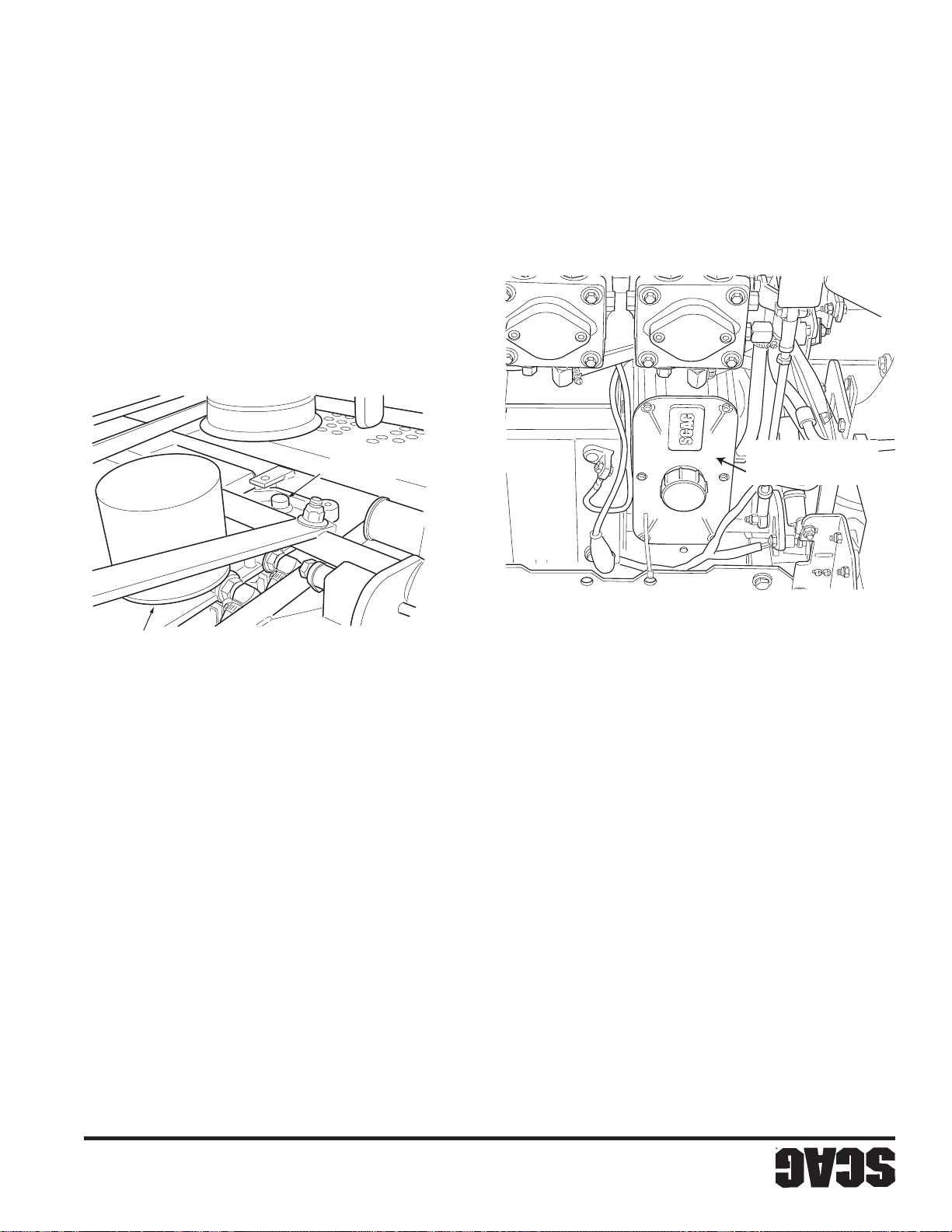
32
aceite hidráulico en la próxima página.
en la sección C -Cambio del elemento del filtro de
debe cambiar el filtro de aceite tal como se describe
Antes de rellenar el depósito de aceite hidráulico,
-NOTA-
de que esté ajustado.
SZC 2005 HOR SP
3. Vuelva a instalar el tapón de drenaje en la T y asegúrese
de drenaje
Figura 7-3 Filtro de aceite hidráulico y Tapón
SZC 2005 HODP SP
Figura 7-2 Depósito de aceite hidráulico
ACEITE HIDRÁULICO
FILTRO DE
ACEITE HIDRÁULICO
TAPÓN DE DRENAJE DE
ACEITE HIDRÁULICO
DEPÓSITO DE
3. Limpie la tapa de relleno y tape el depósito.
puede causar pérdidas de aceite).
DEMASIADO; (llenar demasiado el depósito de aceite
apropiadamente.
drenar el fluido en el recipiente y deséchelo
del fondo del depósito. (Vea la Figura 7-3). Permita
la tapa de llenado del depósito y el tapón del drenaje
bajo, agregue aceite para motor 20W50. NO LLENAR
lleno por debajo del cuello del llenador. Si el fluido está
aceite hidráulico debe estar en la lengüeta que indica
2. V erifique visualmente el nivel de aceite hidráulico. El
aceite hidráulico. Incline el asiento hacia adelante. Quite
2. Coloque un recipiente adecuado debajo del filtro de
depósito de aceite hidráulico.
alrededor de la tapa del depósito. Quite la tapa del
detenga el motor.
1. Limpie la suciedad y las sustancias contaminantes de
1. Estacione el cortacésped en una superficie plana y
inmediatamente.
presencia de agua o se percibe un olor rancio.
El aceite hidráulico se debe cambiar si se nota la
-IMPORTANTE-
-IMPORTANTE-
constante, revise si existen pérdidas y corríjalas
Si el nivel de aceite se encuentra bajo de manera
Sección 7
habitualmente la presencia de agua.
posible recalentamiento del aceite, y un color lechoso indica
color negro y/o un olor rancio indican generalmente un
debe cambiar si se ha vuelto de color negro o lechoso. Un
forma anual, lo que ocurra primero. El aceite también se
El aceite hidráulico se debe cambiar cada 500 horas o en
B. Cambio de aceite hidráulico
máquina o mensualmente, lo que ocurra primero.
aceite después de cada 200 horas de operación de la
las primeras 10 horas de operación. Después, verifique el
El nivel del aceite hidráulico se debe verificar después de
A. Verificar el nivel de aceite hidráulico
7.3 SISTEMA HIDRÁULICO
Page 75
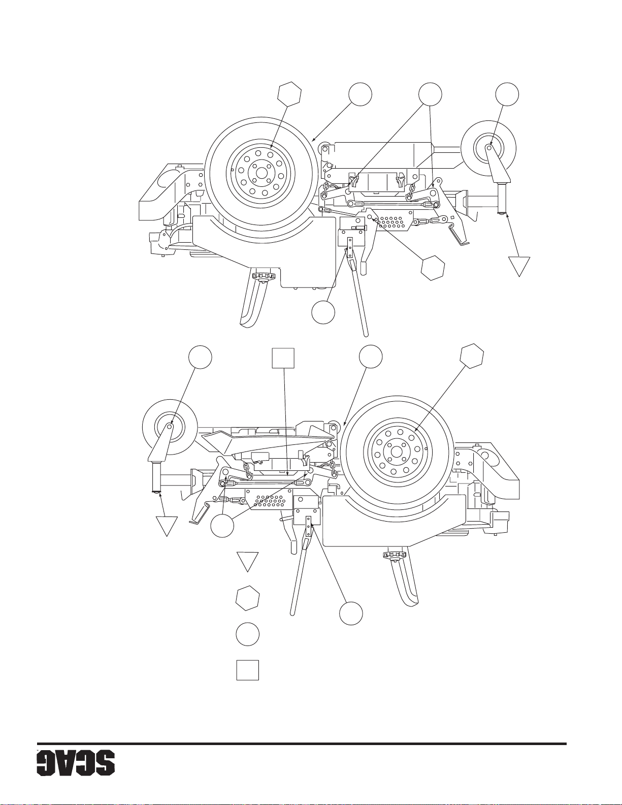
31
Figura 7.1 Lubricación de puntos de conexión
SZC 2005 LFP SP
2
3542
8
6
7
5
3
1
1
4
(500 horas/anualmente)
Grasa de chasis
(200 horas/mensualmente)
Grasa de chasis
6
(100 horas/cada dos meses)
Grasa de chasis
(40 horas/semanalmente)
Grasa blanca de litio MP 2125
Intervalo de lubricación
CONEXIONES DE GRASA DE LUBRICACIÓN
Sección 7
Page 76
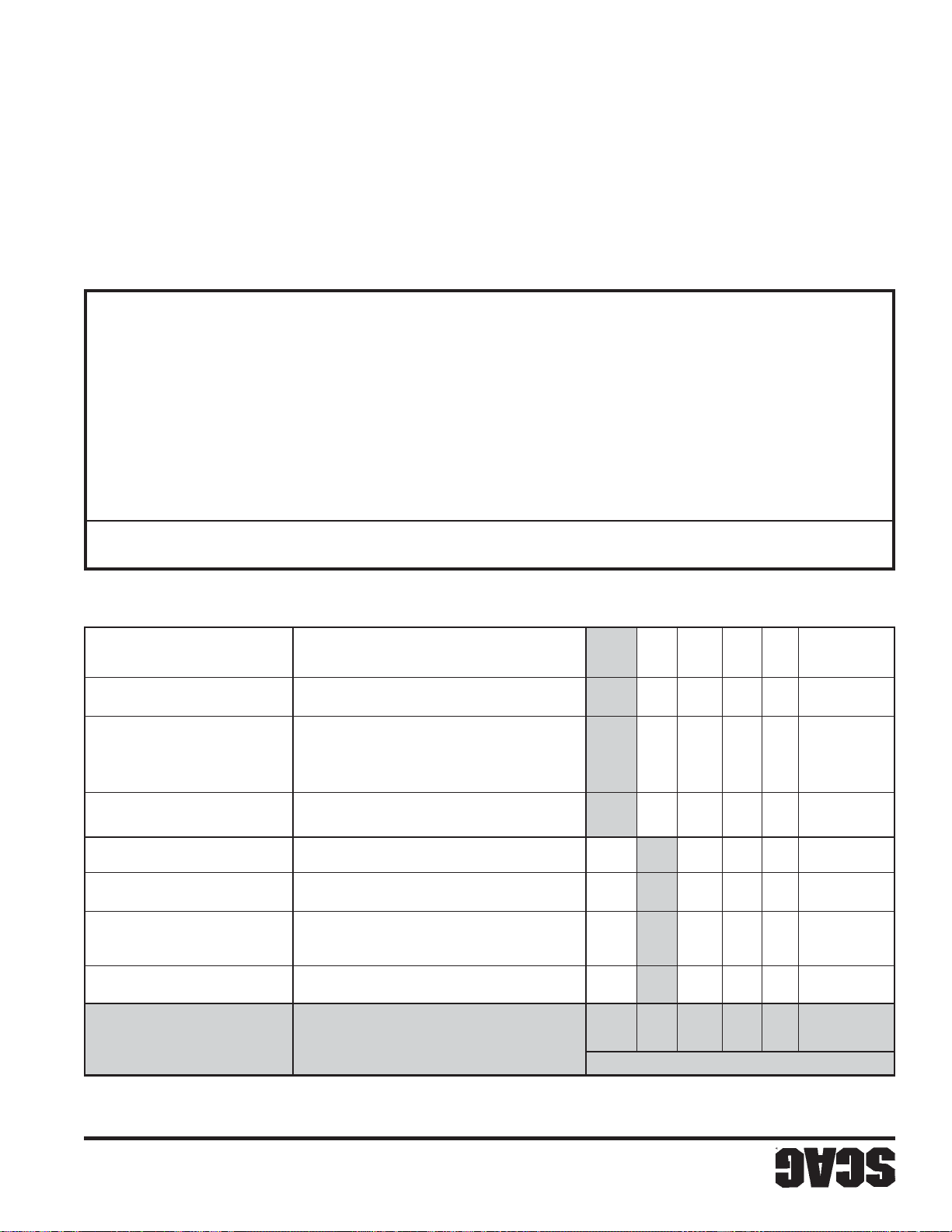
30
Lidok EP #2 encontrada en almacenes industriales
Shell Alvania #2 encontrada en estaciones de servicio Shell
Super Lube MEP #2 y Super Stay-M #2 encontradas en estaciones de servicio Conoco
Ronex MP encontrada en estaciones de servicio Exxon
+ Grasas compatibles: Mobilix #2 encontrada en estaciones de servicio Mobil
grasa. Se recomienda usar la herramienta especial número de parte 47007 para la instalación de la tapa de grasa.
rior de la extensión de la rueda libre. Quite el engrasador y vuelva a instalar el tapón. Vuelva a instalar la tapa de
482028-01, e instale un engrasador. Aplique grasa a la conexión hasta que aparezca nueva grasa en la parte supe* PROCEDIMIENTO: Quite la tapa de la grasa, número de parte 481559. Quite el tapón, número de parte
8 Mango del freno 200 horas/mensualmente Grasa de chasis 1
7 Eje de la plataforma de corte 40 horas/semanalmente +Grasa blanca de litio MP 2125 3
6 Pivote de control 100 horas/cada dos semanas Grasa de chasis 2
5 Brazos de empuje de plataforma de corte 100 horas/cada dos semanas Grasa de chasis 2
4 Balancines de plataforma de corte 100 horas/cada dos semanas Grasa de chasis 4
3 Accionador de freno 200 horas/mensualmente Grasa de chasis 2
2 Rodamientos de la rueda loca 100 horas/cada dos semanas Grasa de chasis 2
1 Pivote de rueda loca * 500 horas/anualmente Grasa de chasis 2
UBICACIÓN LUBRICACIÓN LUBRICANTE LUGARES
INTERVALO DE Nº DE
distribuidor Scag
SAE 20W50
X Ajuste el embrague eléctrico PTO Consulte con el
X Reemplace el filtro de aceite hidráulico Vea el párrafo 7.3
reemplace el aceite hidráulico Use aceite para motor
X Drene el sistema hidráulico y Vea el párrafo 7.3
del motor
X Reemplace el filtro de combustible Vea el párrafo 7.5
ajustada
X V erifique el nivel del aceite hidráulico V ea el párrafo 7.3
X Cambie el filtro de aceite del motor Vea el párrafo 7.4
X V erifique que la tornillería esté bien
X Aplique grasa a las conexiones Vea el párrafo 7.2
HORAS
7.2 LUBRICACIÓN - TABLA DE LUBRICACIÓN DE ACCESORIOS (VEA LA FIGURA 7-1)
(Primeros 10)
8 40 100 200 500 Procedimiento Observaciones
Uso inicial
Sección 7
TABLA DE MANTENIMIENTO - INTERVALOS DE SERVICIO RECOMENDADOS (CONTINUACIÓN)
Page 77
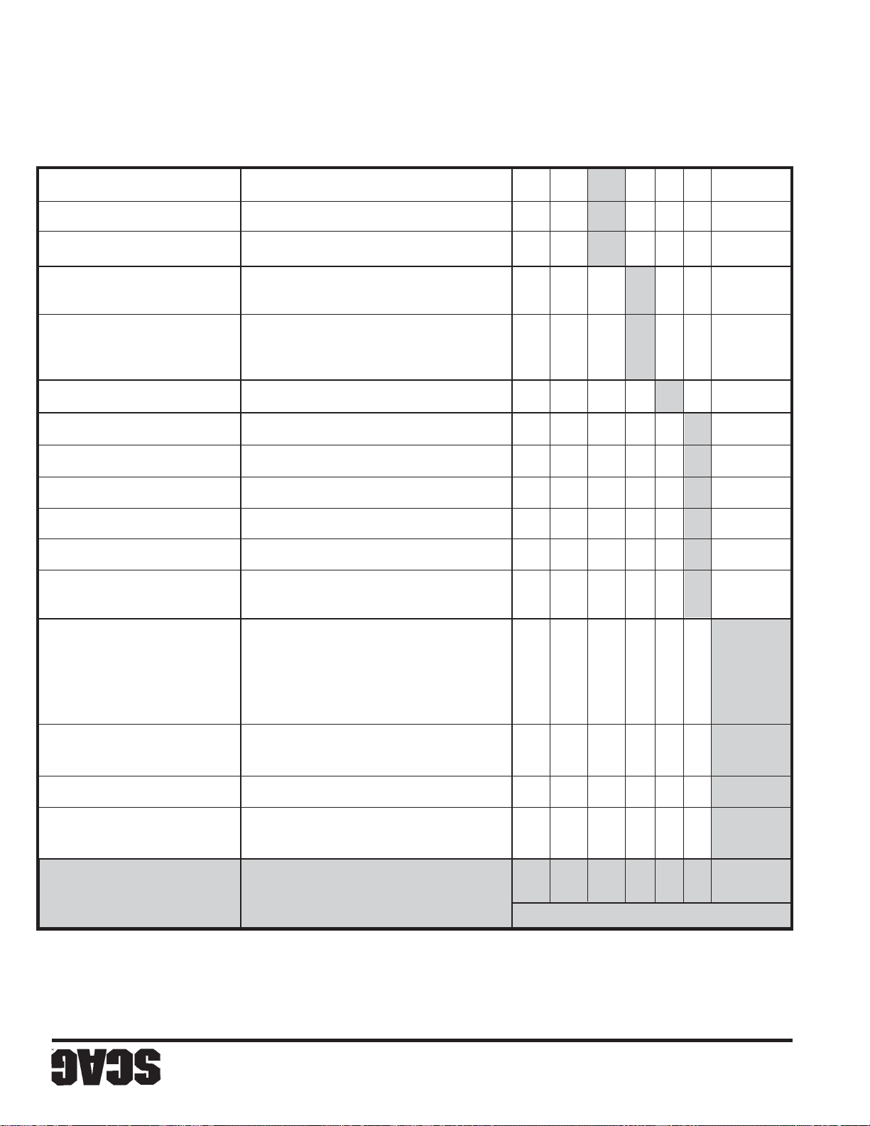
29
polvo o suciedad.
* Realice con más frecuencia estos procedimientos de mantenimiento bajo condiciones extremas de
X *Limpie el elemento del filtro de aire V ea el párrafo 7.6
X Cambie el aceite del motor Vea el párrafo 7.4
X Aplique grasa a las conexiones Vea el párrafo 7.2
las correas
X Verifique la correcta alineación de Vea el párrafo 7.8
de la misma
la batería, limpie los bornes y los cables
X V erifique el nivel de electrolito de V ea el párrafo 7.7
X Cambie el aceite del motor y el filtro Vea el párrafo 7.4
X Revise la presión de las llantas Vea el párrafo 7.10
Vea el párrafo 26
mangueras hidráulicas
presenta deterioro
las mangueras hidráulicas cuidado al verificar las
de todas las correas
bien ajustada
X Aplique grasa a las conexiones Vea el párrafo 7.2
X Verifique el estado de las cuchillas Vea el párrafo 7.9
X *Limpie el cortacésped Vea el párrafo 7.11
X Verifique el nivel de aceite del motor V ea el párrafo 7.4
X Revise si el cinturón de seguridad Vea el párrafo 2.5
X Verifique que no haya fugas en Tenga mucho
X V erifique la correcta alineación Vea el párrafo 7.8
X V erifique el nivel del aceite hidráulico V ea el párrafo 7.3
X V erifique que toda la tornillería esté
(Primeros 10)
8 20 40 100 200 500 Procedimiento Observaciones
Uso inicial
HORAS
7.1 TABLA DE MANTENIMIENTO - INTERVALOS DE SERVICIO RECOMENDADOS
MANTENIMIENTO
Sección 7
Page 78
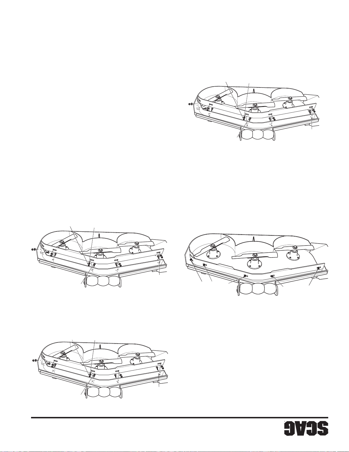
28
de corte personalizado
Figura 6-8. Posición 3" del deflector
2004 CCB - 4" Setting SP
DE TOPE
TUERCA ELÁSTICA
PLANA
ARANDELA
de corte personalizado
Figura 6-10. Posición 4" del deflector
2004 CCB SP
2004 CCB - 3" Setting SP
DE TOPE
TUERCA ELÁSTICA
PERNO DEL CARRO
PLANA
ARANDELA
AJUSTE DE 3"
DE AGUJEROS PARA
CONJUNTO SUPERIOR
tornillos con un torque de 39 pies-lb.
muestra. (Vea las Figuras 6.8 hasta 6.10). Apriete los
4. Vuelva a instalar los accesorios de montaje como se
para la ubicación).
posición deseada. (Vea las Figuras 6.8 hasta 6.10
3. Mueva el deflector de corte personalizado a la
Figura 6-7. Deflector de corte personalizado
DE TOPE
TUERCA ELÁSTICA
2004 CCB - 3-1/2" Setting SP
PERNO DEL CARRO
Sección 6
AJUSTE DE 4"
PERNO DEL CARRO
DE AGUJEROS PARA
CONJUNTO INFERIOR
de corte personalizado
Figura 6-9. Posición 3-1/2" del deflector
PLANA
ARANDELA
DE MONTAJE
TORNILLERÍA
DE MONTAJE
TORNILLERÍA
acuerdo con el tamaño de la plataforma de corte.
ubicación de los accesorios puede variar de
ilustraciones es sólo para referencia. La
La ubicación de los accesorios usados en las
-NOTA-
Figura 6.7).
corte personalizado a la plataforma de corte. (Vea la
2. Quite los accesorios que aseguran el deflector de
transporte.
AJUSTE DE 3 ½"
AGUJEROS PARA EL
CONJUNTO CENTRAL DE
1. Coloque la plataforma de corte en posición de
Para ajustar la altura del deflector de corte personalizado:
Page 79
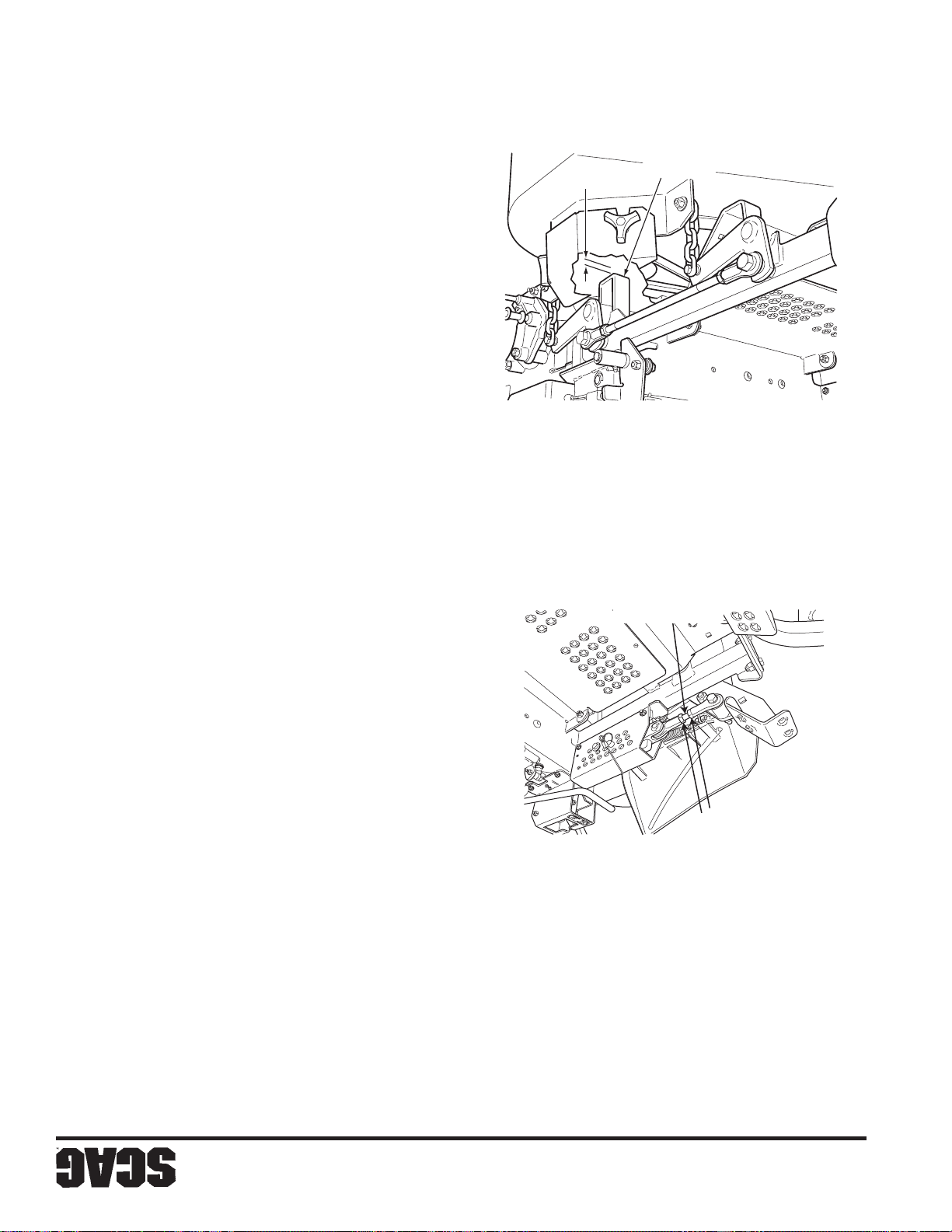
27
Figura 6-6. Tope de la plataforma de corte
y reducirá los “soplos” en la plataforma de corte.
de 4" mejorará el corte en otoño (recogida de hojas)
Figura 6.10). La colocación del deflector en el ajuste
SZC 2005 CDS SP
1/4"
LA PLATAFORMA
TOPE DE
soldado dentro de la plataforma de corte. (Vea la
conjunto inferior de agujeros en el deflector frontal
C. Posición 4" - el deflector se instala usando el
tipos de césped.
combinación de desempeño de corte en todos los
en la posición de 3-1/2". Esto le da la mejor
general, coloque el deflector de corte personalizado
corte. (Vea la Figura 6.9). Para cortes de propósito
deflector frontal soldado dentro de la plataforma de
instala usando el conjunto central de agujeros en el
B. Posición 3-1/2" (ajuste de fábrica) - el deflector se
alto, tieso y difícil de cortar.
entregará la mejor calidad de corte en césped muy
Figura 6.8). La plataforma de corte Advantage
soldado dentro de la plataforma de corte. (Vea la
conjunto superior de agujeros en el deflector frontal
A. Posición 3" - el deflector se instala usando el
de corte
diferentes para el desempeño óptimo.
El deflector se puede colocar en tres (3) posiciones
VARILLA DE CONTROL
plataforma para el tipo de césped que se está cortando.
personalizar en forma precisa el desempeño de la
personalizado puede levantarse o bajarse para
superior en cualquier tipo de césped. El deflector
entregar un óptimo flujo de aire y un desempeño de corte
El deflector de corte personalizado está diseñado para
contratuercas en la varilla de control.
de corte. (Vea la Figura 6-6). Apriete las
de la plataforma y la parte superior de la plataforma
que haya un espacio de 1/4" entre el tope posterior
2. Gire la varilla de control (Vea la Figura 6-6) hasta
Figura 6-5. Ajuste de la altura de la plataforma
Ajuste del deflector de corte personalizado
fácilmente en la posición de transporte.
la plataforma de corte se pueda bloquear
Si se tuvo que realizar un ajuste, asegúrese que
-NOTA-
6-5).
de control de altura de la plataforma. (Vea la Figura
en 3", puede realizarse un ajuste utilizando la varilla
la cuchilla de corte. Si la medida no se encuentra
4. Verifique la medida desde el suelo hasta la punta de
desplace a la posición de la altura de corte de 3".
de la posición de transporte y permita que se
indicador de la altura de corte. Libere la plataforma
colocando el pin de amarre en la posición 3" en el
3. Verifique la altura de corte de la plataforma de corte
AQUÍ
AFLOJE
plataforma. (Vea la Figura 6-5).
extremos de la varilla de control de la altura de
transporte. Afloje las contratuercas en ambos
1. Coloque la plataforma de corte en posición de
apropiadamente.
superficie plana y a nivel y que las llantas estén infladas
plataforma, asegúrese que el cortacésped esté en una
en el indicador. Para verificar la altura apropiada de la
para asegurar que la misma corte en la altura señalada
El ajuste de la altura de la plataforma de corte se realiza
Altura de la plataforma de corte
Sección 6
Page 80
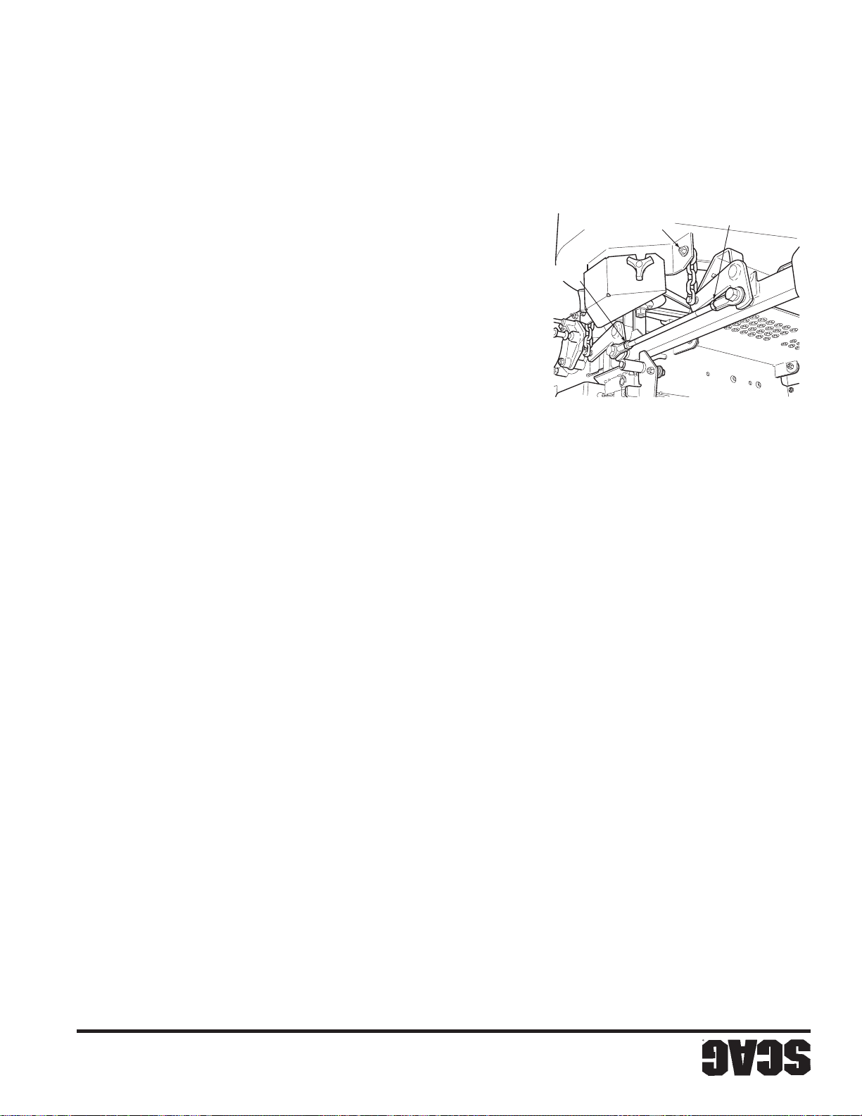
26
O
tienen un borde inferior disparejo.
plataforma, ya que las plataformas Advantage
deben tomarse desde el borde superior de la
mencionados anteriormente. Todas las medidas
de corte como se explicó en los procedimientos
plataforma oscila, debe reajustar la plataforma
las cuatro cadenas no están bajo tensión y la
plataforma de corte deben estar tensionadas. Si
corte, las cuatro cadenas suspendidas de la
DE CORTE
DE PLATAFORMA
PERNO DE AJUSTE
Para evitar la oscilación de la plataforma de
-NOTA-
de corte. Apriete ambas tuercas de bloqueo.
TUERCA DE BLOQUE
frontal a la posterior a ambos lados de la plataforma
hasta que la plataforma esté igual desde la parte
varillas de ajuste en la parte no roscada de la varilla
2. Usando unos alicates de mandíbula ajustable, gire las
ajuste. (Vea la Figura 6-4).
1. Afloje las tuercas de bloqueo en ambas varillas de
Figura 6-4. Ajuste de la plataforma de corte
TUERCA DE BLOQUEO
siguiente:
inclinación de la plataforma debe ajustarse de la manera
parte frontal de la plataforma no es la misma, la
izquierdo de la plataforma de corte. Si la medida en la
plataforma. También realice estas medidas en el lado
corte debe ser la misma que en la parte posterior de la
corte. La medida en la parte frontal de la plataforma de
frente de las cadenas suspendidas de la plataforma de
frontal del lado derecho de la misma directamente en
superior de la plataforma de corte hasta el piso en el lado
corte. Luego verifique la distancia desde la parte
detrás de las cadenas suspendidas de la plataforma de
lado derecho de la plataforma de corte directamente
plataforma de corte hasta el piso en el lado posterior del
Verifique la distancia desde la parte superior de la
las llantas estén infladas apropiadamente.
cortacésped esté en una superficie plana y a nivel y que
inclinación apropiada de la plataforma, asegúrese que el
desempeño de corte apropiado. Para verificar la
entre la parte frontal y posterior de la misma para un
La inclinación de la plataforma de corte debe ser igual
Inclinación de la plataforma de corte
-NOTA-
(Vea la Figura 6-4).
de corte, ubique el perno de ajuste de la misma.
1. En el lado frontal del lado izquierdo de la plataforma
corte se debe ajustar como sigue:
dos medidas son diferentes, el nivel de la plataforma de
la máquina. Ambas medidas deben ser iguales. Si las
plataforma de corte hasta el piso en el lado izquierdo de
Luego revise la distancia desde la parte superior de la
parte superior de la plataforma de corte hasta el piso.
derecho de la máquina, verifique la distancia desde la
altura de corte más común que usará. En el lado
apropiadamente y la plataforma de corte esté fijada en la
superficie plana y nivelada, las llantas estén infladas
nivel, asegúrese que el cortacésped esté en una
para un desempeño apropiado de corte. Para verificar el
La plataforma de corte debe ser plana de lado a lado
Nivel de la plataforma de corte
llantas se inflen apropiadamente.
plataforma de corte, asegúrese de que todas las
Antes de proceder con los ajustes de la
plataforma de corte en la posición apropiada.
3. Apriete la tuerca elástica de tope para asegurar la
de la plataforma de corte.
procedimientos lo ayudarán a obtener el ajuste apropiado
realizarse estos ajustes alguna vez, los siguientes
derecho de la máquina.
misma al piso sea igual que la medida del lado
altura se ajustan en fábrica. Sin embargo, si deben
El nivel de la plataforma de corte, la inclinación y la
plataforma de corte hasta que la distancia de la
hacia arriba o hacia abajo en la ranura para ajustar la
2. Afloje la tuerca elástica de tope y mueva el perno
CORTE
6.6 AJUSTES DE LA PLATAFORMA DE
Sección 6
Page 81
ADVERTENCIA:
25
consulte con su centro de servicio autorizado Scag.
experimenta un frecuente desgaste o rotura de correas,
desempeño apropiado de su cortacésped Scag. Si
La alineación de la correa es importante para el
6.5 ALINEACIÓN DE LA CORREA
-NOTA-
correcta alineación y el desgaste de las correas.
auto tensionantes. Deben revisarse periódicamente la
plataforma de corte están cargadas por resortes y son
Todas las correas de transmisión y las correas de la
el motor y retire la llave de encendido.
Antes de quitar cualquier guarda, apague
condición, proceda de la manera siguiente:
gira más rápido que la izquierda. Para ajustar esta
izquierda, es una indicación de que la rueda derecha
2. Si a máxima velocidad el cortacésped se tira a la
describe en la página 24.
neutral debe hacerse de la manera que se
lentamente hacia adelante o hacia atrás, el ajuste
explicó en el paso 1A, la máquina avanza
Si después de realizar el ajuste tal como se
de dicho lado. (Vea la Figura 6-3).
izquierdo, disminuyendo la velocidad de la rueda
varilla de control golpee menos la bomba del lado
las tuercas de bloqueo. Esto causará que la
varilla de control para acortar la varilla y apriete
control de dirección del lado izquierdo. Gire la
juntas de rótula en cada extremo de la varilla de
Afloje las tuercas de bloqueo que aseguran las
control de dirección en la posición neutral.
A. Detenga la máquina y coloque las palancas de
condición, proceda de la manera siguiente:
6.4 AJUSTE DE LA CORREA
centro de servicio autorizado Scag.
motor. Si requiere cualquier ajuste, contacte con su
Scag para asegurar la operación apropiada y eficiente del
estrangulación deben ser realizados por su distribuidor
Los ajustes de los controles de aceleración y
ACELERACIÓN Y ESTRANGULACIÓN
6.3 AJUSTES DE LOS CONTROLES DE
describe en la página 24.
neutral debe hacerse de la manera que se
lentamente hacia adelante o hacia atrás, el ajuste
explicó en el paso 2A, la máquina avanza
Si después de realizar el ajuste tal como se
-NOTA-
del lado derecho. (Vea la Figura 6-3, página 24).
derecho, disminuyendo la velocidad de la rueda
varilla de control golpee menos la bomba del lado
las tuercas de bloqueo. Esto causará que la
varilla de control para acortar la varilla y apriete
control de dirección del lado derecho. Gire la
juntas de rótula en cada extremo de la varilla de
Afloje las tuercas de bloqueo que aseguran las
control de dirección en la posición neutral.
A. Detenga la máquina y coloque las palancas de
-NOTA-
PRECAUCIÓN:
PRECAUCIÓN:
gira más rápido que la derecha. Para ajustar esta
derecha, es una indicación de que la rueda izquierda
1. Si a máxima velocidad el cortacésped se tira a la
máquina tirará al lado con la presión más baja.
Si la presión de la llanta no es correcta, la
de las llantas en las ruedas motrices es correcta.
las ruedas locas giren libremente y que la presión
Antes de proceder con este ajuste, asegúrese que
realizar cualquier ajuste.
componentes de transmisión se enfríen antes de
quemaduras. Permita que el motor y los
durante la operación, causando heridas por
El motor y la unidad motriz pueden calentarse
comenzar a trabajar.
todas las partes móviles se detengan antes de
antes de realizar cualquier ajuste. Espere que
Detenga el motor y quite la llave del encendido
Ajuste de alineación
Sección 6
Page 82
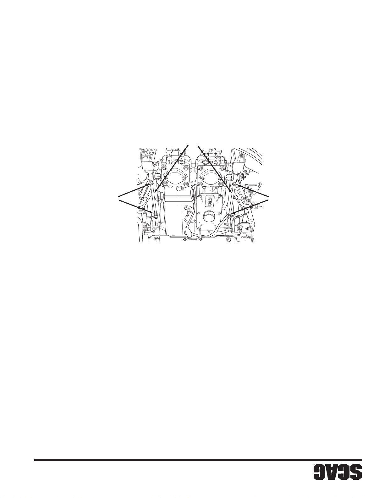
24
AQUÍ
AJUSTE
Figura 6-3. Ajuste de varillas de control de dirección
AFLOJE AQUÍ
DIRECCIÓN
DE CONTROL DE
VARILLA DERECHA
AFLOJE AQUÍ
DIRECCIÓN
DE CONTROL DE
VARILLA IZQUIERDA
necesario.
carrera completa. Ajuste como lo considere
golpeen el tope antes de que las bombas alcancen la
8. Compruebe que las palancas de control de dirección
neutral y ajuste de nuevo si es necesario.
7. Compruebe que las ruedas motrices permanezcan en
neutral.
adelante y en reversa y regréselas a la posición
6. Accione las palancas de control de dirección hacia
rueda izquierda.
5. Apriete las contratuercas y repita el proceso para la
hacia atrás. (Vea la Figura 6-3).
deje de moverse. Gire la varilla 1/2 vuelta adicional
varilla en sentido contrario hasta que la rueda motriz
hasta que la rueda motriz gire hacia adelante. Gire la
en la varilla de control de dirección y gire la varilla
4. Ajuste la rueda izquierda aflojando las contratuercas
libere el freno de estacionamiento.
2. Con un operador en el asiento, arranque el motor y
neutral de bloqueo.
palancas de control de dirección estén en la posición
descarga estén en la posición de operación y que las
1. Asegúrese de que las palancas de la válvula de
Ajuste neutral
Vea página 25).
desplazarse hacia adelante. (Ajuste de alineación,
cortacésped se tira a un lado o al otro al
posición completamente hacia adelante y el
B. Las palancas del control de dirección están en la
adelante o hacia atrás. (Vea Ajuste neutral).
posición neutral y la máquina se arrastra hacia
A. Las palancas de control de dirección están en la
Sección 6
o hacia atrás.
y compruebe si la máquina se arrastra hacia adelante
3. Opere el motor a la máxima velocidad de operación
Se tendrán que realizar ajustes neutrales o de alineación si:
6.2 AJUSTES DE DESPLAZAMIENTO
Page 83
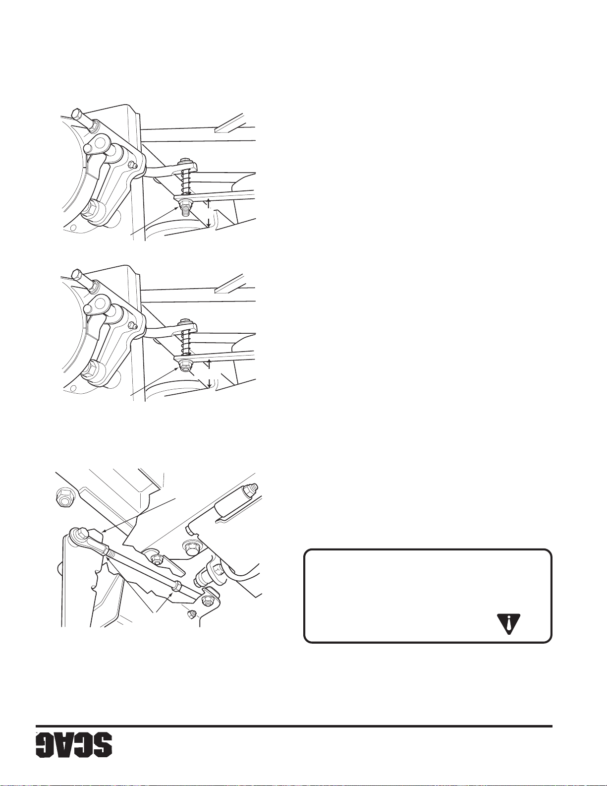
23
7. Reemplace las ruedas motrices y pruebe el freno.
SZC 2005 BRA SP
AQUÍ
APRIETE
2"
Figura 6-2. Ajuste de la varilla de freno
barra del accionador hasta alcanzar la medida de 2".
apriete o afloje la tuerca en la parte superior de la
aproximadamente 2". Si la medida no es de 2",
la barra del accionador. Esta medida debe ser de
6. Verifique la medida en el lado RH entre el bastidor y
barra del accionador sea aproximadamente de 2".
accionador hasta que la medida entre el bastidor y la
apriete la tuerca en la parte superior de la barra del
5. Cuando se haya alcanzado la medida de 1-1/4",
Apriete las contratuercas. (Vea la Figura 6-1).
la varilla hasta alcanzar la distancia apropiada.
extremos de la varilla de control del freno y girando
Realice el ajuste aflojando la contratuerca en ambos
especificado, ajuste la varilla de control del freno.
1-1/4". Si esta medida no está en el valor 1-1/4"
de la barra del accionador. La distancia debe ser de
3. Mida la distancia entre el bastidor y la parte superior
perno. (Vea la Figura 6-2, vista superior).
accionador hasta que esté a nivel con el extremo del
2. Afloje la tuerca en la parte superior de la barra del
SZC 2005 BA SP
AQUÍ
AFLOJE
AQUÍ
AFLOJE
1-1/4"
Figura 6-1. Ajuste de freno
DEL FRENO
MANGO
motrices.
evitar que la máquina se mueva. Quite las ruedas
evitar que caiga. Bloquee las ruedas locas para
de la máquina. Levante la máquina y apóyela para
1. Coloque un gato de piso debajo de la parte posterior
freno.
su distribuidor Scag para cualquier ajuste adicional de
freno de estacionamiento apropiadamente, contacte con
Si los procedimientos siguientes no permiten accionar el
estacionamiento no evitará que el cortacésped se mueva.
coloca en la posición “ENGAGE”; el freno de
cuando la palanca del freno de estacionamiento se
El acople del freno de estacionamiento debe ajustarse
graves.
funcionamiento. Podrían causarse lesiones
estacionamiento no está en correcto estado de
NO opere el cortacéspedes si el freno de
ADVERTENCIA:
de Scag.
del freno, contacte con su distribuidor autorizado
Si este procedimiento no logra el ajuste apropiado
-NOTA-
ESTACIONAMIENTO
6.1 AJUSTE DEL FRENO DE
AJUSTES
Sección 6
Page 84
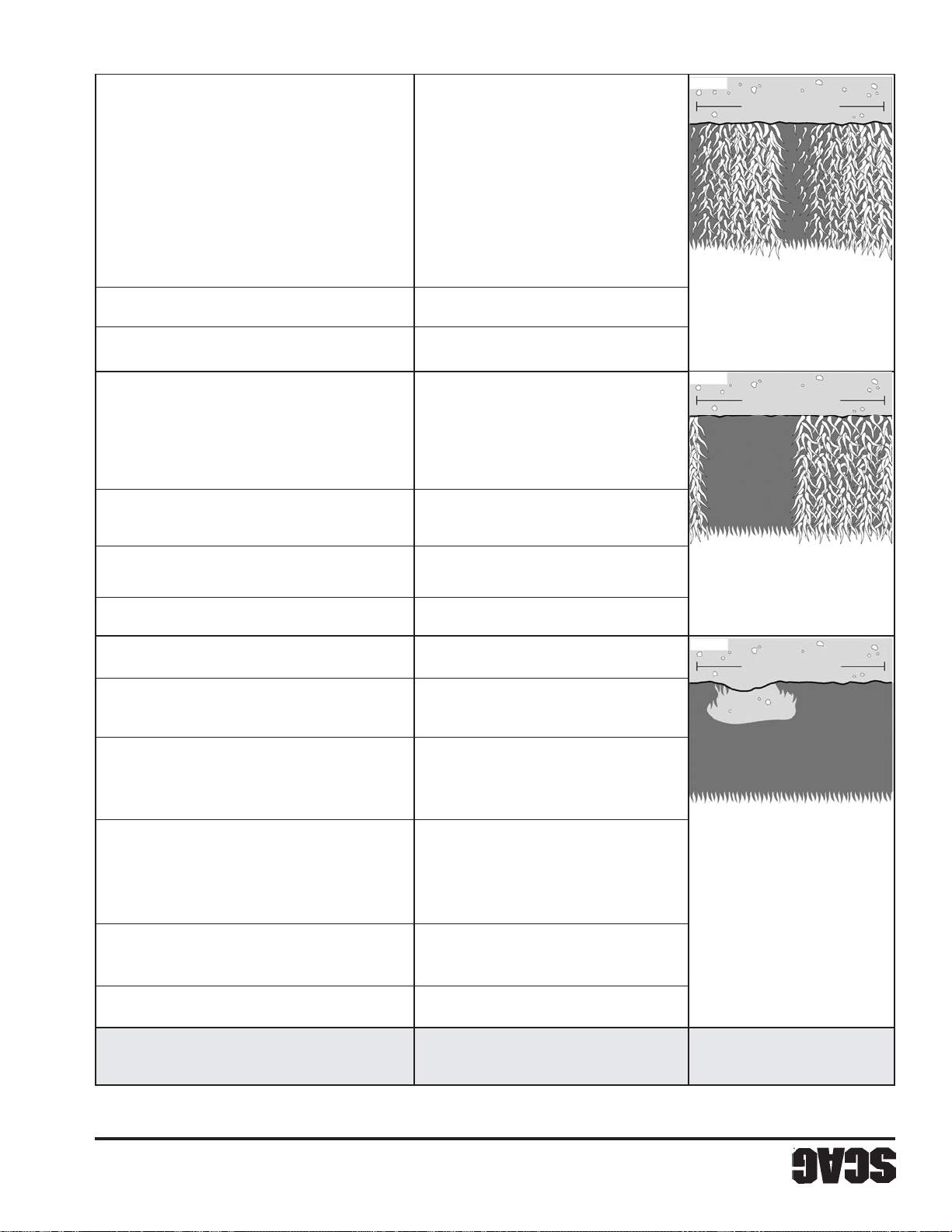
22
Alojamiento de la plataforma doblado Consulte con su distribuidor Scag autorizado
Montaje incorrecto del eje Consulte con su distribuidor Scag autorizado
Falla del eje interno Consulte con su distribuidor Scag autorizado
SGB 025
SGB 024
plataforma de corte
Ancho de la
la trayectoria de corte
través del ancho de Falla del eje interno Consulte con su distribuidor Scag autorizado
Crestas inclinadas a
Corte inclinado - Área de montaje del eje doblada Consulte con su distribuidor Scag autorizado
plataforma de corte
Ancho de la
Césped mojado Corte el césped una vez que se seque
condiciones del terreno
Velocidad demasiado alta Disminuya la velocidad para ajustarse a las
de corte y/o cambiar la dirección del corte
terreno, aumentar la altura de la plataforma
Terreno rugoso Se puede tener que reducir la velocidad en el
cambiar la inclinación y el nivel
de corte, cambiar la dirección del corte y/o
terreno, aumentar la altura de la plataforma
Corte demasiado bajo Se puede tener que reducir la velocidad en el
la trayectoria de corte Cuchilla doblada Reemplace la cuchilla
en el centro de
Corte lateral - Cresta Cuchillas mal montadas, disparejas Ajuste la inclinación y el nivel
SGB 022
plataforma de corte
Ancho de la
muy cerca al terreno a las condiciones del terreno
tierra o están cortando elocidad demasiado alta Disminuya la velocidad para ajustarse
cuchillas pegan en la
Raspadoras - Las Baja presión de las llantas Verifique y ajuste las presiones
Sección 5
SOLUCIÓN
CAUSA
CONDICIÓN
SOLUCIÓN DE FALLAS (CONTINUACIÓN)
Page 85
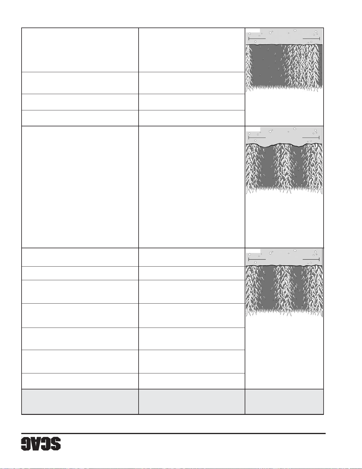
21
SGB 023
Plataforma no nivelada lado a lado Verifique el nivel y corrija
incorrectamente
Plataforma de corte montada Consulte con su distribuidor Scag autorizado
SGB 021
plataforma de corte
Ancho de la
trayectoria de corte Ruedas disparejas Revise y ajuste la presión de las llantas
a lo ancho de la
Salientes inclinadas Llantas con presión desequilibrada Revise y ajuste la presión de las llantas
plataforma de corte
Ancho de la
o perfil irregular
ondulada, corte volado dirección del corte
Apariencia baja y alta plataforma de corte y/o cambiar la
terreno disparejo - en el terreno, aumentar la altura de la
Corte disparejo en Terreno disparejo Se puede tener que reducir la velocidad
Cuchilla desafilada Afile la cuchilla
SGB 020
plataforma de
Ancho de la
Área del eje doblada Consulte con su distribuidor Scag autorizado
incorrectamente
Plataforma de corte montada Consulte con su distribuidor Scag autorizado
(inclinación de la plataforma de corte)
Demasiado ángulo en la cuchilla Ajuste la inclinación y el nivel
plataforma de corte
Césped acumulado debajo de la Limpie la parte de abajo de la plataforma
o perfil irregular
ondulada, corte volado, terreno
Apariencia baja y alta Cuchilla montada invertida Monte la cuchilla con el filo hacia el
terreno plano Corte disparejo en Levantador de la cuchilla desgastado Reemplace la cuchilla
SOLUCIÓN
CAUSA
CONDICIÓN
SOLUCIÓN DE FALLAS (CONTINUACIÓN)
Sección 5
Page 86
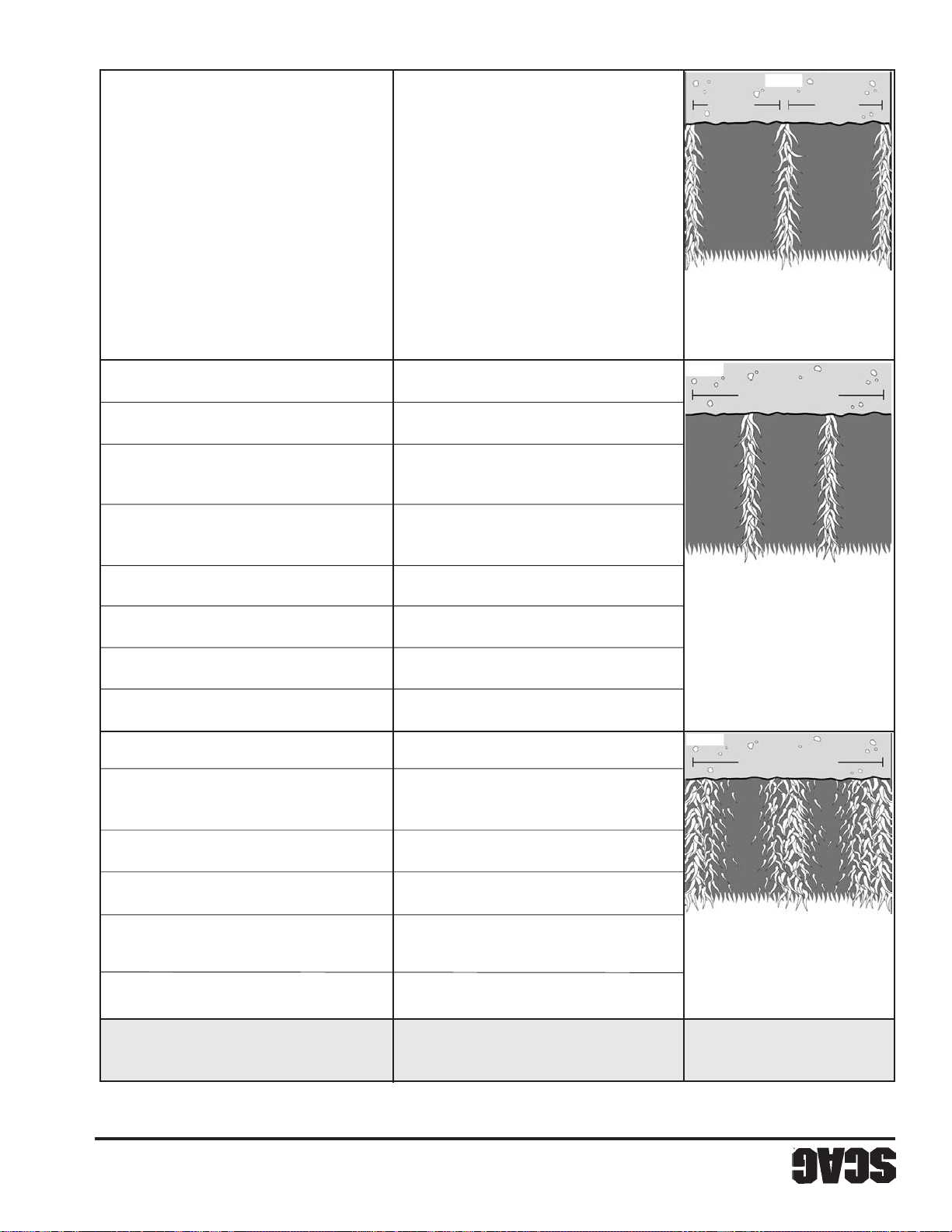
20
las condiciones del terreno
SGB
de corte
plataforma
Ancho de la
Cuchillas dobladas Reemplace las cuchillas
SGB 018
Césped mojado Corte el césped una vez que se seque
Velocidad demasiado alta Disminuya la velocidad para ajustarse a
plataforma de corte
Césped acumulado debajo de la Limpie la parte de abajo de la plataforma
de corte
plataforma
Ancho de la
trayectorias de corte
césped sin cortar entre pasadas
Vetas - Franjas de Traslape insuficiente entre Aumente el traslape de cada pase
plataforma de corte
Ancho de la
las condiciones del terreno
Correa patinando Ajuste la tensión de la correa
Bajas revoluciones (RPM) del motor Opere el motor a su máxima RPM
Correas patinando Ajuste la tensión de la correa
SGB 020
plataforma de corte
Césped acumulado debajo de la Limpie la parte de abajo de la plataforma
Cuchillas desafiladas, afilado incorrecto Afile las cuchillas
Césped mojado Corte el césped una vez que se seque
Velocidad demasiado alta Disminuya la velocidad para ajustarse a
la trayectoria de corte Afilado incorrecto de las cuchillas Afile las cuchillas
césped sin cortar en
Vetas - Franjas de Cuchillas desafiladas o desgastadas Afile las cuchillas
plataforma de corte
Ancho de la
irregular de césped
Largueros - Corte Bajas revoluciones (RPM) del motor Opere el motor a su máxima RPM
Sección 5
SOLUCIÓN
CAUSA
CONDICIÓN
IDENTIFICACIÓN DE FALLAS EN LAS CONDICIONES DE CORTE
Page 87
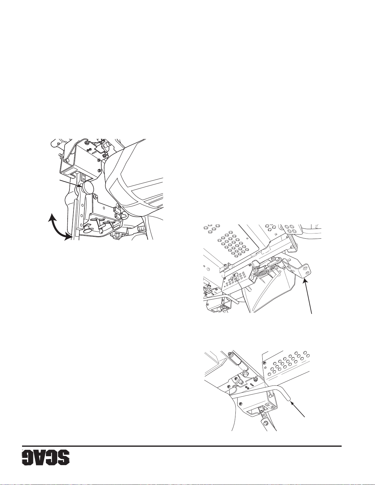
TENSIÓN
PERILLA DE
19
deseada.
palanca de control. Instale el mango en la posición
dos pernos que aseguran el mango de control a la
dos diferentes posiciones. Si es necesario, quite los
4. El mango de control también puede ser ajustado en
Figura 4-6 Ajuste de las palancas de dirección
ROTACIÓN
PALANCA DE
palancas estén niveladas antes de operar.
neutral de bloqueo y verifique que ambas
las palancas de dirección fuera de la posición
D. Al encontrarse en la posición de operador, lleve
en el lado opuesto.
C. Apriete la perilla de tensión y repita el proceso
funcionamiento.
hacia atrás para lograr una óptima posición de
B. Gire la palanca de dirección hacia adelante o
palanca.
A. Afloje la perilla de tensión en el conjunto de la
aplique las siguientes instrucciones.
3. Si es necesario el ajuste de las palancas de dirección,
Figura 4-5 Ajuste de altura de corte
DE ALTURA
PEDAL DE AJUSTE
Figura 4-4 Palanca de liberación de la plataforma
control total y comodidad.
hacia adelante y hacia atrás para verificar que tenga
motor apagado, mueva ambas palancas de dirección
2. Al encontrarse en la posición de operador con el
1. Coloque el asiento en la posición deseada.
4.14 Ajuste de las palancas de dirección
PLATAFORMA
LIBERACIÓN DE LA
PALANCA DE
Sección 4
Page 88
ADVERTENCIA:
18
altura deseada. (Figura 4-5).
altura como una ayuda para ajustar la plataforma a la
la altura de plataforma ubicada en el indicador de
Libere lentamente el pedal. Hay una calcomanía de
palanca de liberación de plataforma, (Figura 4-4).
plataforma, manténgala en posición y levante la
adelante la palanca de pie de la elevación de
de corte en la altura de corte deseada. Empuje hacia
3. Inserte el pin de amarre en el indicador de la altura
4-5, Página 19).
derecho hasta que se asegure en su lugar. (Figura
corte completamente hacia adelante con su pie
2. Empuje el pedal de pie de ajuste de la altura de
1. Desconecte la potencia a las cuchillas de corte.
de corte.
a las cuchillas de corte y luego ajuste la altura
cortacésped estén girando. Desconecte la potencia
No ajuste la altura de corte cuando las cuchillas del
ADVERTENCIA
DESCARGA, O SIN EL RECOGEDOR DE CÉSPED INSTALADOS.
NO OPERE SIN EL EQUIPO MEZCLADOR DE PAJA DE LA TOLVA DE
propiedad debido a objetos lanzados.
mismos para reducir la posibilidad de daños a la
cerca de obstáculos, dirija la descarga lejos de los
limpieza de los recortes de césped. Cuándo corte
lateral lejos de aceras o de calles para minimizar la
se encuentre sobre el mismo. Dirija la descarga
hacia abajo el césped cortado y cualquier objeto que
mantenerse en su posición más baja para desviar
2. La tolva de descarga no debe quitarse y debe
requiriendo potencia adicional del motor.
resultado una mala apariencia del césped y
desafilada desgarrará el césped, dando como
1. No corte con cuchillas desafiladas. Una cuchilla
EL CÉSPED
4.12 RECOMENDACIONES PARA CORTAR
Para ajustar la altura de corte:
una altura de 1-1/2" hasta 5-1/2" en intervalos de 1/4".
La plataforma del cortacésped puede ajustarse desde
4.13 AJUSTE DE LA ALTURA DE CORTE
los patrones en el mismo.
cada vez que corte el césped para evitar estropear
apariencia del césped. Varíe la dirección de la franja
8. Use el patrón de franjas alternas para mejorar la
operarse a la máxima velocidad.
desgarrará el césped. El motor está diseñado para
corte. Si corta a una RPM más baja, el cortacésped
7. Opere el motor a máxima aceleración para un mejor
desee recortar.
6. Use una baja velocidad de desplazamiento cuando
la altura deseada.
para el primer pase y luego haga un segundo pase en
veces. Levante el cortacésped al ajuste más alto
5. Cuando corte césped mojado o césped alto, corte dos
descarga.
4. Mantenga limpios el cortacésped y la tolva de
apariencia). Corte frecuentemente.
o menos del césped existente para obtener una mejor
alto. No corte el césped demasiado corto (corte 1/3
3. Corte el césped cuando esté seco y no demasiado
PELIGRO:
cortacésped.
DRIVE y ajustadas a 7-10 pies/lb para operar el
válvula de descarga deben ser regresadas a la posición
mueve el cortacésped a mano. Las palancas de la
Página 14). Desconecte el freno de estacionamiento y
descarga en la posición FREE-WHEEL (Figura 4-2,
motor encendido, coloque las palancas de la válvula de
Para “rodar libremente” o mover el cortacésped sin el
CON EL MOTOR DETENIDO
4.11 DESPLAZAMIENTO DEL CORTACÉSPED
Luego, reanude el corte normal.
artículo semejante para sacar el material atascado.
motor y quita la llave de encendido. Use un palo o
1. Si la tolva de descarga llega a atascarse, apague el
semejante para quitar el material atascado.
la llave y sólo entonces use un palo u objeto
ocurrido una obstrucción, apague el motor y quite
DESCARGA POR NINGÚN MOTIVO! Si ha
¡NUNCA PONGA LAS MANOS EN LA TOLVA DE
CUCHILLAS GIRATORIAS
4.10 RETIRO DEL MATERIAL ATASCADO
Sección 4
Page 89
17
es necesario.
5. V erifique la presión de las llantas. Corrija la presión si
propietario del motor para saber el octanaje apropiado.
combustible con combustible limpio. V ea el manual del
cortacésped se haya enfriado, llene los tanques de
4. Al final de cada día de operación y después de que el
combustible y rellenar.
se enfríe antes de quitar la tapa del tanque de
Para evitar quemaduras, permita que el cortacésped
PELIGRO:
ajuste si es necesario.
transmisión y cualquier señal de desgaste. Corrija y
3. Verifique la correcta alineación de las correas de
5. Mantenga las llantas correctamente infladas.
pérdida de frenado o dirección.
que las ruedas motrices se deslicen, causando
a la parte delantera de la máquina y puede causar
desplazarse bajando una cuesta. El peso se transfiere
4. Puede producirse una pérdida de tracción al
se incline hacia atrás.
arranques repentinos pueden causar que la máquina
3. Evite arranques repentinos al subir una cuesta. Los
baje lentamente la pendiente.
llantas pierden tracción, desconecte las cuchillas y
innecesarios y desplácese a baja velocidad. Si las
ni se detenga repentinamente, evite giros
2. Para evitar volcarse o perder el control, no arranque
circuito de aceite hidráulico.
severos daños por calentamiento al motor o al
2. Mantenga limpio todo el cortacésped para impedir
caliente.
comprimido para limpiar el motor si está
El agua fría dañará el motor. Use aire
No lave un motor caliente ni en operación.
-IMPORTANTE-
componentes eléctricos.
use chorro a alta presión ni dirija el chorro sobre
1. Lave todo el cortacésped después de cada uso. No
4.9 DESPUÉS DE LA OPERACIÓN
la llave.
6. Gire la llave de encendido a la posición OFF y quite
5. Accione el freno de estacionamiento.
de vacío.
4. Disminuya la velocidad del motor hasta la velocidad
3. Desconecte las cuchillas de corte.
posición neutral.
2. Coloque las palancas de control de dirección en la
pendiente.
nivel solamente. No estacione la máquina en una
1. Estacione el cortacésped en una superficie plana y a
ADVERTENCIA:
4.8 ESTACIONAMIENTO DEL CORTACÉSPED
mayores detalles.
la Sección 2.5, página 7 de este manual para
vuelco es un equipo estándar para esta máquina. Vea
control de dirección. El sistema de protección contra
mojado. El césped mojado reduce la tracción y el
cuestas, especialmente cuando el césped está
corte. Sin embargo, debe tener cuidado al viajar en
tracción y estabilidad bajo condiciones normales de
1. Este cortacésped se ha diseñado para tener buena
OPERACIONES APROBADAS POR OSHA.
extremo cuidado. SIEMPRE CUMPLA CON LAS
se resbalen, reduzca la velocidad y opere con
puede retroceder por la pendiente sin que las ruedas
(con la plataforma de corte baja). Si la máquina
si puede trabajar en una cuesta, trate de retroceder
NO OPERE en pendientes empinadas. Para probar
4.7 OPERACIÓN EN UNA CUESTA
y permita que el motor opere a sus máximas RPM.
exceso de carga, reduzca la velocidad hacia adelante
el motor comienza a disminuir su velocidad por
mantener apropiadamente la velocidad de corte. Si
4. Siempre opere el motor a máxima aceleración para
empuje el interruptor a la posición de desconexión.
3. Para desconectar la transmisión de la plataforma,
Sección 4
Page 90
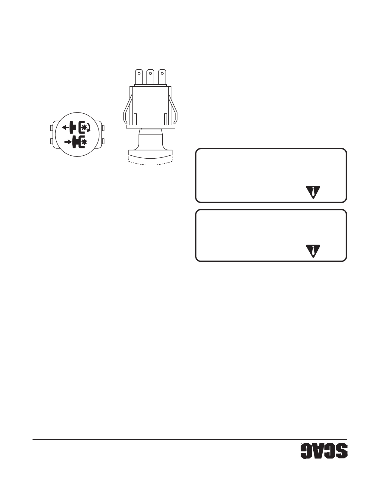
STT99CES SP
plataforma de corte
DESCONECTAR
PRESIONE HACIA ABAJO PARA
TIRE HACIA ARRIBA PARA ACCIONAR
-NOTA-
16
Figura 4-3 Interruptor de accionamiento de la
-NOTA-
adquiere velocidad. Esto es normal.
embrague eléctricos mientras el cortacésped
Es causado por el engrane de los platos del
desconectar la transmisión de la plataforma.
Puede escucharse un chirrido al accionar o
instrumentos, (Figura 4-3) a la posición accionada.
interruptor amarillo, ubicado en el panel de
2. Accione la transmisión de plataforma tirando del
cortacésped a la izquierda.
desplazarse hacia adelante, más rápido girará el
mueva hacia adelante. Cuanto más se permita al control
reversa, permite que la palanca izquierda de dirección se
Para dirigirse a la izquierda mientras se desplaza en
ajustes con los controles de dirección.
recta en reversa. Deben hacerse ligeros
El cortacésped no puede desplazarse en línea
desplazamiento al viajar en reversa.
ambas asas hacia atrás. Mantenga baja la velocidad de
palancas fuera de la posición neutral de bloqueo y tire
Para desplazarse en reversa, tire hacia adentro las
personales o daños a la propiedad.
antes de retroceder. Pueden ocurrir lesiones
obstrucciones en la parte posterior. Despeje el área
Antes de retroceder, observe si hay personas y
PRECAUCIÓN:
toda el área detrás del cortacésped.
absolutamente necesario y sólo después de observar
retroceder. No corte en reversa a menos que sea
Desconecte la potencia al cortacésped antes de
PRECAUCIÓN:
transmisión de plataforma.
velocidad moderada del motor al accionar la
esto acorta la vida del embrague eléctrico — use una
transmisión de la plataforma en alta velocidad ya que
velocidad máxima. No trate de accionar la
1. Ponga el control de aceleración en cerca de 3/4 de la
PLATAFORMA (CUCHILLAS DE CORTE)
4.6 CONEXIÓN DE LA TRANSMISIÓN DE
-IMPORTANTE-
estacionamiento.
en la posición neutral de bloqueo, y accione el freno de
Si el cortacésped debe ser estacionado, coloque las asas
las palancas de dirección vuelvan a la posición neutral.
Para detener el desplazamiento en reversa, permita que
cortacésped a la derecha.
desplazarse hacia adelante, más rápido girará el
mueva hacia adelante. Cuanto más se permita al control
reversa, permite que la palanca derecha de dirección se
Para dirigirse a la derecha mientras se desplaza en
-NOTA-
Desplazamiento en reversa
sobre como levantar la plataforma de corte).
sección 4.1, artículo 12 para instrucciones
reborde en un ángulo de 45 grados. (vea la
plataforma y desplácese hacia atrás sobre el
detenerse sobre el reborde. Levante la
reborde de una acera. El cortacésped puede
No se desplace hacia adelante sobre el
velocidad de desplazamiento.
controles de dirección, mantenga baja la
cortacésped. Mientras aprende a operar los
dirección producirá una operación suave del
La operación suave de las palancas de
palancas, más rápido girará el cortacésped a la derecha.
dirección hacia atrás. Cuanto más atrás se tiren las
desplaza hacia adelante, tire la palanca derecha de
Para dirigir el cortacésped a la derecha mientras se
Sección 4
Page 91
15
palancas, más rápido girará el cortacésped a la izquierda.
dirección hacia atrás. Cuanto más atrás se tiren las
desplaza hacia adelante, tire la palanca izquierda de
Para dirigir el cortacésped a la izquierda mientras se
posición neutral.
palancas de control de dirección nuevamente a la
Para detener el desplazamiento hacia adelante, tire de las
cerca de la mitad de la velocidad del motor.
5. Mueva el control de aceleración del motor hasta
necesaria.
4. Si el motor está frío, cébelo de la forma que sea
hacia atrás.
más adelante y para disminuirla, tire de las palancas
velocidad, empuje las palancas de control de dirección
palancas, mayor será la velocidad. Para aumentar la
distancia similar. Cuanto más adelante se empujen las
lentamente las palancas de dirección hacia adelante una
hacia adentro sacándolas de la posición neutral y empuje
libere el freno de estacionamiento, lleve las palancas
Para desplazarse hacia adelante con el cortacésped,
3. Accione el freno de estacionamiento.
control de dirección en la posición neutral.
cinturón de seguridad y coloque las palancas de
2. Siéntese en el asiento del operador, asegure el
abierta. (Vea la sección 7.5).
tanque izquierdo de combustible, esté completamente
ubicada detrás del asiento del operador cerca del
1. Asegúrese de que la válvula de corte de combustible,
Desplazamiento hacia adelante
operación uniforme.
controles de dirección para obtener una
Aprenda a controlar con suavidad los
desplazándose lentamente hacia adelante.
Comience practicando a baja velocidad y
-IMPORTANTE-
de operar en pendientes.
Aprenda la operación en terreno plano antes
la máquina antes de tratar de cortar.
hasta que se sienta cómodo con el manejo de
edificios, cercas, u obstrucciones. Practique
en el terreno en un área abierta, lejos de
las operaciones de conducción y velocidad
transmisiones hidrostáticas, debe practicar
una máquina con dirección de palanca y/o
Si no está familiarizado con la operación de
-IMPORTANTE-
PRECAUCIÓN:
causar daños al motor y/o lesiones personales.
condición de “embalamiento” del motor que puede
puede ser potencialmente explosivo o causar una
líquidos de arranque en el sistema de toma de aire
NO USE LÍQUIDOS DE ARRANQUE. El uso de
4.4 ARRANQUE DEL MOTOR
es necesario. (Vea la sección 7.10).
6. Revise la presión de las llantas. Corrija la presión si
(Vea la sección 4.2).
5. Revise la correcta operación del sistema de bloqueo.
sea necesario.
4. Revise que no haya tornillería floja. Apriete según
Y DIRECCIÓN
4.5 DESPLAZAMIENTO EN EL TERRENO
cortacésped.
7. Permita que el motor se entibie antes de operar el
dañar el arrancador y acortar la vida de batería.
arrancador. Los arranques prolongados pueden
cada intento de arranque para evitar sobrecalentar el
segundos. Permita por lo menos 60 segundos entre
la llave en la posición START por más de 15
suéltela en cuanto arranque el motor. No mantenga
6. Gire la llave de encendido a la posición ST ART y
(Vea la sección 7.3).
3. V erifique el nivel de aceite hidráulico en el depósito.
(Vea la sección 7.4).
después de las primeras 20 horas de operación.
2. Cambie el aceite de motor y el filtro de aceite
y su desgaste a las 2, 4 y 8 horas.
1. Verifique la correcta alineación de todas las correas
aproximadamente 10 horas)
INICIAL (Primer día de uso o
4.3 PROCEDIMIENTOS DE ARRANQUE
Sección 4
Page 92
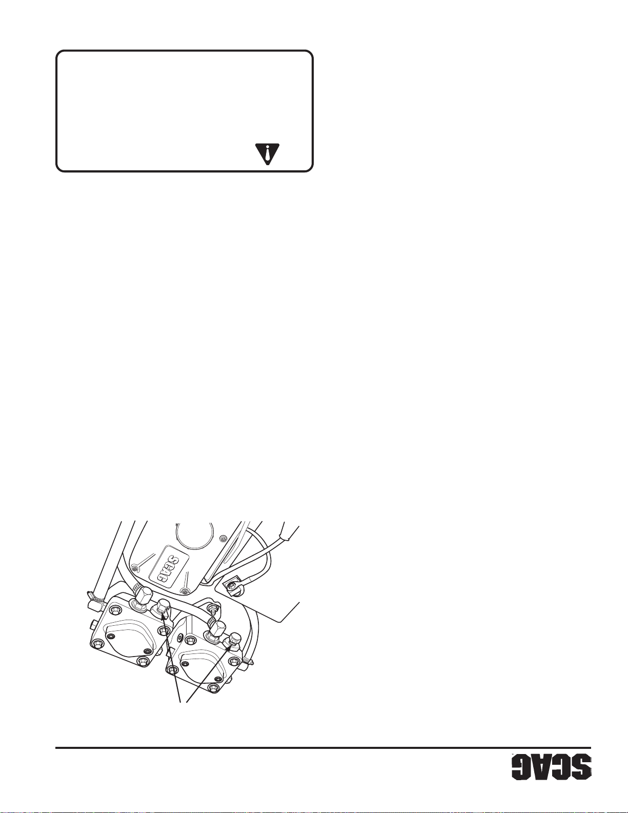
ADVERTENCIA:
DE DESCARGA
CONTROL DE VÁLVULA
14
daños a la propiedad.
provocarle lesiones a usted o a terceros o causar
puente ningún interruptor; el hacerlo puede
defectuosamente. No desconecte ni ponga en
bloqueo desconectado o funcionando
Nunca opere el cortacésped con el sistema de
estacionamiento no accionado.
y/o las cuchillas de corte accionadas y/o el freno de
control de dirección en una posición distinta de la neutral
motor si el operador deja el asiento con las palancas de
operador en el asiento. El sistema de bloqueo apaga el
de control de dirección en la posición neutral y el
el freno de estacionamiento esté accionado, las palancas
que la transmisión de plataforma esté desconectada, que
de seguridad que evita que el motor arranque a menos
El cortacésped está equipado con un sistema de bloqueo
SEGURIDAD
4.2 SISTEMA DE BLOQUEO DE
usarse durante toda la operación.
asegurar al operador. El cinturón de seguridad debe
15 . Cinturón de seguridad (Figura 4-1). Usado para
plataforma de corte.
palanca de desenganche de modo de soltar la
normal, empuje el pedal hacia adelante y levante la
corte en la posición de transporte. Para corte
(Figura 4-1). Usada para trabar la plataforma de
14. Palanca de liberación de la plataforma de corte
Figura 4-2 Control de válvula de descarga
corte deseada.
para poner la plataforma de corte en la altura de
13 . Ajuste de la altura de corte (Figura 4-1). Usado
plataforma de corte.
(Figura 4-1). Usada para levantar y bajar la
12. Palanca de pie de elevación de plataforma
el cortacésped se mueva a mano (rueda libremente).
contrario a las agujas del reloj, 1-2 vueltas, permite que
del cortacésped. El giro de las palancas en el sentido
posición y apretadas a 10 pies/lb durante la operación
potencia hidráulica. Las válvulas deben estar en esta
que se detengan permite que la unidad se mueva con
palancas en el sentido de las agujas del reloj hasta
“rodar libremente” el cortacésped. El giro de las
Ubicadas en las bombas hidráulicas, se usan para
11. Control de válvula de descarga (Figura 4-2).
combustible solamente del tanque del lado derecho.
sentido de las agujas del reloj para suministrar
tanque del lado izquierdo. Gire la válvula en el
del reloj para suministrar combustible solamente del
Gire la válvula en contra del sentido de las agujas
cambiar la alimentación de combustible entre tanques.
para cortar el suministro del combustible al motor y
Ubicada en el lado izquierdo de la máquina. Usada
10 . Válvula de cambio de combustible (Figura 4-1).
para desconectar los frenos de estacionamiento.
los frenos de estacionamiento. Presione la palanca
de estacionamiento. Tire de la palanca para accionar
4-1). Usado para accionar y desconectar los frenos
9. Control del freno de estacionamiento (Figura
cortacésped al avanzar hacia adelante o en reversa.
Usado para controlar la rueda derecha del
8. Control derecho de dirección (Figura 4-1).
cortacésped al avanzar hacia adelante o en reversa.
Usado para controlar la rueda izquierda del
7 . Control izquierdo de dirección (Figura 4-1).
zócalo e instale uno nuevo.
Para reemplazar los fusibles, retire el fusible del
Amp protegen el sistema eléctrico del cortacésped.
6 . Portafusibles (Figura 4-1). Dos fusibles de 20
después. Reinicia automáticamente.
establecida y continuará destellando hasta 2 horas
empezará a destellar 2 horas antes de la hora
sistema hidráulico. El mantenimiento programado
mantenimiento del motor y los cambios de aceite del
posición ON. Ha fijado los recordatorios para el
interruptor de la llave de encendido está en la
horas que ha operado el motor. Opera cuando el
5 . Horómetro (Figura 4-1). Indica el número de
Sección 4
Page 93
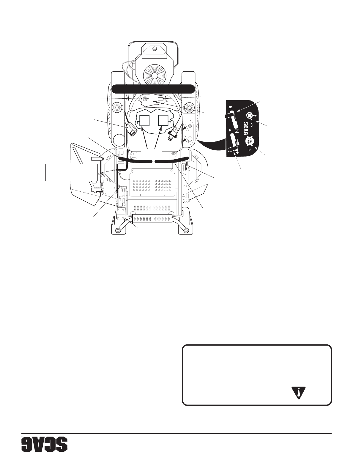
SZC 2005 CAI SP
OFF
ON
START
FAST
SLOW
13
Figura 4-1 Controles e Instrumentos
DE COMBUSTIBLE
VÁLVULA DE CAMBIO
SEGURIDAD
CINTURÓN DE
DE DIRECCIÓN
CONTROL DERECHO
PLATAFORMA DEl CORTE
LIBERACIÓN DE LA
PALANCA DE
ALTURA DE CORTE
AJUSTE DE
HORÓMETRO
FUSIBLES
DESCARGA
VÁLVULA DE
LA PLATAFORMA
ELEVACIÓN DE
CHOKE
SLOW
FRENO DE
DE DIRECCIÓN
FAST
POWER EQUIPMENT
TO ENGAGE
PULL OUT
OFF
ON
START
MOWER DECK
PUSH IN TO
DISENGAGE
ESTACIONAMIENTO
CONTROL IZQUIERDO
de más adelante.
MARCHA EN VACÍO. La posición de corte es la
completamente hacia atrás es la posición de
atrás disminuye la velocidad del motor. La posición
velocidad del motor. T irando de la palanca hacia
Presionando la palanca hacia abajo aumenta la
Usado para controlar la velocidad de motor.
4 . Control de aceleración del motor (Figura 4-1).
DEL MOTOR
ESTRANGULACIÓN
CONTROL DE
DE ENCENDIDO
INTERRUPTOR
DEL CORTACÉSPED
LA PLATAFORMA
INTERRUPTOR DE
CONTROL DE ACELERACIÓN DEL MOTOR
ON, y START.
para arrancar el motor; tiene tres posiciones; OFF,
1 . Interruptor de encendido (Figura 4-1). Usado
cortacésped.
estos controles para la operación segura y eficiente del
importante conocer la ubicación, función y operación de
todos los controles del cortacésped y el motor. Es
Antes de operar el cortacésped, debe familiarizarse con
INSTRUMENTOS
4.1 IDENTIFICACIÓN DE CONTROLES E
4-1). Usado para arrancar un motor frío.
3 . Control de estrangulación del motor (Figura
la transmisión de plataforma.
plataforma. Presione el interruptor para desconectar
del interruptor para accionar la transmisión de
el sistema de transmisión del cortacésped. Tire
PRECAUCIÓN:
(Figura 4-1). Usado para accionar y desconectar
2 . Interruptor de la plataforma del cortacésped
INSTRUCCIONES DE OPERACIÓN
antes de operar este cortacésped.
propósito de todos los controles e instrumentos
haya leído este manual. Aprenda la ubicación y el
No trate de operar este cortacésped a menos que
Sección 4
Page 94

12
Acres por día: 14 16
Ancho de corte: 36" 42"
La tabla es un estimado basado en un tiempo de corte de 8 horas por día, a 6 KPH, con una cuota de 20% para traslape y giros.
La tabla siguiente lo ayudará a determinar cuántos acres cortará su cortacésped Scag por día.
3.7 PRODUCTIVIDAD
Depósito hidráulico.................................................................... Aluminio fundido; capacidad 2 cuartos
Filtro de aceite hidráulico ........................................................... Tipo roscado (spin-on) de 10 micras
3.6 SISTEMA HIDRÁULICO
Tipo embrague eléctrico............................................................. Embrague PTO de servicio pesado Ogura
SMZC42 ................................................................................ Números de parte Scag - 483002
SMZC36 ................................................................................ Números de parte Scag - 483001
Correas de la plataforma de corte: .............................................. Sección B, de Kevlar. Auto ajustado, auto apretado
................................................................................................... cónicos de fácil desmontaje
Poleas del eje:............................................................................. Hierro fundido (SZC36A), acero partido (SZC42A) con cubos
de grasa
de grasa en la parte superior y cabezal móvil de alivio de exceso
rodamiento de rodillos cónicos, bajo mantenimiento con conexión
Ejes:............................................................................................Servicio pesado, 1-1/8" en la parte superior, cuerpo fundido,
................................................................................................... por resorte y deflector turbo
Abertura de descarga:................................................................ Abertura de descarga extra ancha con tolva de descarga cargada
.................................................................................................. una correa
.................................................................................................. de panel de control conectado a la plataforma de corte mediante
Accionamiento de las cuchillas:................................................ Embrague eléctrico de accionamiento de cuchilla con interruptor
................................................................................................... desgaste
Cuchillas de corte:...................................................................... Grosor 197, borde cepillado, material Marbain™ resistente al
................................................................................................... 1.50" a 5.5" en incrementos de 1/4"
Ajuste de altura de corte: ........................................................... Ajuste con palanca de pie desde el asiento del operador, desde
Ancho de corte: ......................................................................... 36" (91.44 cm), 42" (106.68 cm)
................................................................................................... plataforma calibre 7 (3/16")
................................................................................................... plataforma consta de dos placas de acero calibres 10 y 7, faldón de
Construcción ............................................................................. Construcción de plataforma de doble placa, la parte superior de la
diseños delantero y de montaje frontal
Tipo :........................................................................................... Flotante, ajustable, anti raspado, de diseño híbrido que combina
Sección 3
las condiciones de corte.
adelante debe ajustarse en función de
velocidad de desplazamiento hacia
Para un mejor desempeño de corte, la
(12 Kph) para fines de transporte.
La máquina se desplazará a 7.5 MPH
-NOTA-
3.4 PLATAFORMA DE CORTE
Reversa.................................................................................. 0-5 MPH (0-8 Kph)
Adelante ................................................................................ 0-7.5 MPH (0-12 Kph)
V elocidad de desplazamiento:
3.3 TRACTOR (CONTINUACIÓN)
Page 95

11
abertura, tapa de combustible y sujetavasos moldeado
ejes de ambas ruedas motrices
el desplazamiento sin operación del motor
Asiento ......................................................................................Moldeado, acolchado
Motriz .................................................................................... 12 P S I
Rueda libre delantera ............................................................. Llantas macizas
Presión de la llanta:
Tanques de combustible ............................................................ Tanque dual de 2.5 galones, de polietileno, sin costuras, con gran
................................................................................................... Sin cámara neumática, de cuatro capas, borde radial
(2) Motrices - (plataforma 48"-52") ........................................ 23 X 8.50 X 12 (SZC36A) 23 X 9.50 X 12 (SZC42A)
(2) Rueda libre en la parte delantera ...................................... 11 X 4-5, cuatro capas, con rodamientos de rodillos cónicos
Ruedas:
Freno de estacionamiento .......................................................... Mecanismo accionado por palanca conectado a los frenos en los
................................................................................................... de gas
................................................................................................... dedos, con control individual de cada rueda con amortiguadores
Control de dirección/desplazamiento ......................................... Control de dirección de doble palanca accionado con la punta de los
Motores de la rueda motriz ........................................................ Dos motores Hydro-Gear™ de hierro fundido de alto torque
Bombas hidrostáticas................................................................. Dos bombas Hydro-Gear™ BDP 10A con válvulas de descarga para
................................................................................................... y dos motores de hierro fundido y alto torque
Sistema de transmisión .............................................................. Transmisión hidráulica con dos bombas de desplazamiento variable
3.3 TRACTOR
interruptor PTO
freno de estacionamiento
solenoide
chorro fijo.
Tipo gasolina, 4 ciclos, dos cilindros, eje vertical
19 HP (Espec. #) (Scag Modelo SZC36A-19KAI, SZC42A-19KAI)
................................................................................................... 17 HP (Espec. #) (Scag Modelo SZC36A-17KAI)
ESPECIFICACIONES
Fusibles...................................................................................... Dos (2) de 20 A mp
T ablero de instrumentos ............................................................ Llave de encendido, palanca de aceleración, estrangulación manual,
Interruptores ..............................................................................Asiento, control de neutral, accionamiento de cortacésped (BBC),
Arrancador................................................................................. Eléctrico, 12 voltios, de corona, bloqueo operado por llave y
Polaridad del sistema ................................................................. Tierra negativa
Salida de carga ........................................................................... 12 Voltios, 13 Amp - Kawasaki
Sistema de carga ........................................................................ Alternador
Batería ........................................................................................ 12 voltios
3.2 SISTEMA ELÉCTRICO
Correa de transmisión de la bomba ............................................ Número de parte Scag - 483000
Correas: ...................................................................................... Correa de Kevlar. Auto ajustado, auto apretado
Arrancador................................................................................. Arranque eléctrico con arrancador de solenoide
Conjunto de bomba de aceite..................................................... Bomba de aceite Gerotor™ de desplazamiento positivo
Combustible ............................................................................... Gasolina sin plomo con un octanaje mínimo de 87
Conjunto de bomba de combustible .......................................... Bomba de combustible tipo pulso con filtro en línea, carburador de
V elocidad en vacío ..................................................................... 1550 RPM - Kawasaki
Controlador ................................................................................ Tipo mecánico con control de velocidad variable fijado en 3600 RPM
Cilindros..................................................................................... 2 con camisas de hierro fundido
Potencia ..................................................................................... 16 HP (Espec. #) (Scag Modelo SZC36A-16HN)
Marca ......................................................................................... Kawasaki, Honda, Briggs & Stratton
Tipo general ............................................................................... Industrial de servicio pesado/Comercial de gasolina
3.1 MOTOR
Sección 3
Page 96
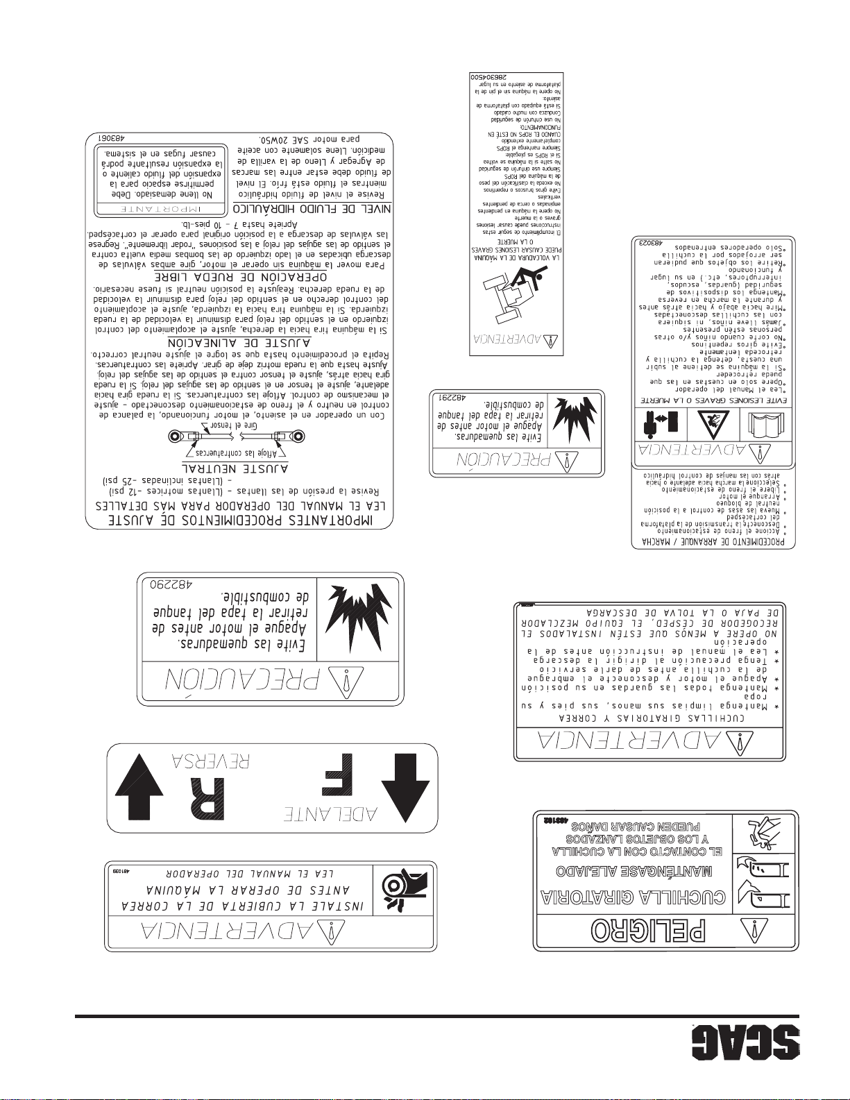
483061
10
2006 SZC Safety Decals SP
483023
482291
482290
482100
481039
482286
483206
Sección 2
2.7 CALCOMANIAS INSTRUCTIVAS Y DE SEGURIDAD
Page 97
9
desgastadas o dañadas.
funcionamiento. Reemplace todas las calcomanías
10. Mantenga todas las partes en buenas condiciones de
NUNCA enderece ni suelde cuchillas.
servicio a las cuchillas. Sólo reemplace las cuchillas.
cuchillas o use guantes y tenga cuidado al dar
9. T enga cuidado al revisar las cuchillas. Forre las
servicio a la máquina.
8. NUNCA permita que personal sin entrenamiento dé
freno de estacionamiento.
7. Estacione la máquina en terreno plano y accione el
aisladas.
batería. Use ropa de protección y herramientas
cargador antes de conectarlo o desconectarlo de la
ventilada, lejos de chispas y llamas. Desenchufe el
17. Cargue las baterías en un área abierta y bien
drenajes bajo techo.
16. NO almacene combustible cerca de llamas ni
transporte.
15. Corte el combustible durante el almacenamiento o el
14. NO almacene la máquina cerca de un fuego abierto.
13. Permita que el motor se enfríe antes de almacenarlo.
gangrena.
horas por un médico o puede producirse una
retirado quirúrgicamente dentro de unas pocas
hidráulico se inyecta en la piel, debe ser
con su distribuidor autorizado Scag. Si el fluido
servicio para su sistema hidráulico, contacte
fluido hidráulico a alta presión. Si necesita
pequeños agujeros o boquillas que expulsan
Mantenga el cuerpo y las manos lejos de los
El fluido hidráulico se encuentra a alta presión.
césped, hojas, exceso de grasa, aceite y suciedad.
unidades de corte, el silenciador y el motor libres de
6. Para reducir el peligro de incendio, mantenga las
información sobre los ajustes del motor.
manual del operador del motor para obtener
opere a mayor velocidad de la nominal. Vea el
5. No cambie los ajustes del controlador del motor ni
para estar seguro de que estén apretados.
frecuencia los pernos de montaje de las cuchillas
condiciones seguras de trabajo. Revise con
tornillos, para asegurar que la máquina esté en
4. Mantenga apretados todos los pernos, tuercas, y
terminal negativo después.
después. Reconecte primero el terminal positivo y el
primero el terminal negativo y el terminal positivo
antes de hacer cualquier reparación. Desconecte
3. Desconecte la batería o retire el cable de la bujía
ajuste, limpieza o reparación.
todo movimiento cese antes de realizar cualquier
dando servicio o ajuste a la máquina. Espere que
evitar un arranque accidental del motor cuando esté
y quite la llave o desconecte el cable de bujía para
ponga el freno de estacionamiento, detenga el motor
2. Desconecte la transmisión, baje los implementos,
ADVERTENCIA:
componentes que tengan energía almacenada.
12. Libere cuidadosamente la presión de los
cuando sea necesario.
11. Use soportes de gato para apoyar componentes
móviles.
las manos, los pies, y la ropa lejos de las piezas
hacerlo así. Si el motor está funcionando, mantenga
operación a menos que se le indique específicamente
1. Nunca realice ajustes a la máquina con el motor en
MANTENIMIENTO Y ALMACENAMIENTO
2.6 CONSIDERACIONES DE
Sección 2
Page 98
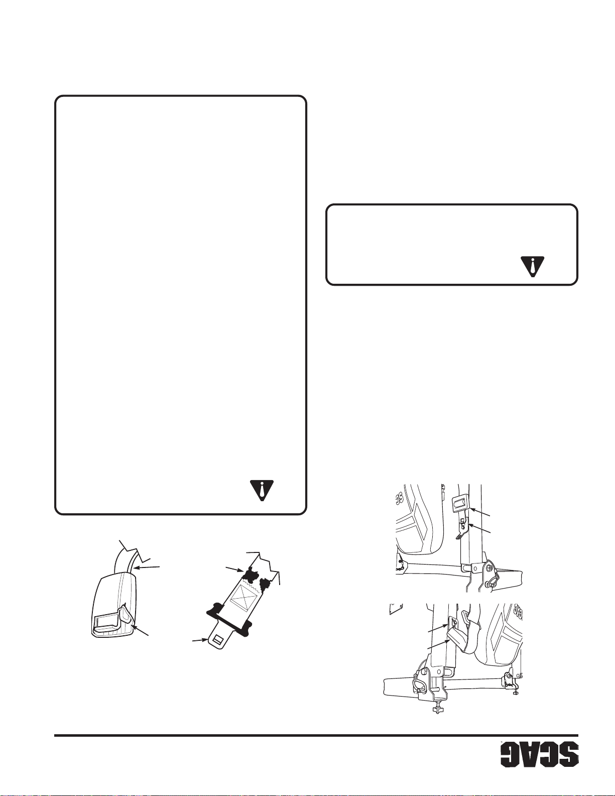
8
la máquina.
NO permita que personal sin entrenamiento opere
pérdida de control.
remolcado puede causar la pérdida de tracción y la
NUNCA remolque en cuestas. El peso del equipo
ni arranques o paradas en una pendiente.
Opere la máquina suavemente, sin giros repentinos,
borde o si el borde se derrumba.
repentinamente si una rueda pasa encima de un
ni terraplenes. La máquina podría volcarse
NO corte cerca de pendientes verticales, zanjas
de seguridad.
estas condiciones, reemplace el sistema del cinturón
de estas correas puede haberse deteriorado. Si existen
decolorado y/o lleno de suciedad, la resistencia física
correas en estas áreas está extremadamente
o a polvo o suciedad extrema. Si el color original de las
en las áreas expuestas a los rayos ultra violeta del sol
2. Revise el tejido de las correas del cinturón de seguridad
rigidez. Vea la Figura 2-4.
detectar si hay cortes, desgaste, roturas, suciedad y
1. Revise la longitud completa de las correas para
puede ocasionar lesiones graves o la muerte.
apropiadamente el cinturón de seguridad
El incumplimiento de inspeccionar y mantener
ADVERTENCIA:
ADVERTENCIA:
TEJIDO DE LA CORREA
INSPECCIONE EL
sobre una pendiente.
de la pendiente cuando sea posible. Nunca cruce
SIEMPRE desplácese hacia arriba o hacia abajo
resbalen, no la opere en dicha pendiente.
puede retroceder en una pendiente sin que las ruedas
(con la plataforma de corte baja). Si la máquina no
si puede trabajar en una cuesta, trate de retroceder
empinadas para una operación segura. Para probar
Manténgase alejado de pendientes demasiado
Permita una distancia adicional para detenerse.
pendientes, o en superficies húmedas o resbaladizas.
Reduzca la velocidad al girar o al operar en
de seguridad
Figura 2-4 Inspección del cinturón de seguridad
DE SEGURIDAD
CINTURÓN
RETENCIÓN
SOPORTE DE
ser reemplazado inmediatamente.
de cierre, tornillería o cualquier otro problema obvio debe
tejido del cinturón de seguridad, o daños a la hebilla, placa
debido a la exposición UV, suciedad o rigidez, abrasión al
desgaste extremo o inusual, decoloración significativa
de cinturón de seguridad que muestre cortes, roturas,
seguridad para detectar señales de daño. Cualquier sistema
Se recomienda examinar diariamente el cinturón de
sistema del cinturón regularmente.
condiciones ambientales severas hace crucial examinar el
La exposición potencial del cinturón de seguridad a
Figura 2-3 Soportes de retención del cinturón
Sección 2
EL SEGURO
HEBILLAS Y
INSPECCIONE LAS
RETENCIÓN
SOPORTE DE
SEGURIDAD
CINTURÓN DE
dañada o agrietada. Vea la Figura 2-4.
excesivamente gastada, deformada, o si la hebilla está
funcionamiento y determine si la placa de cierre está
3. Revise la hebilla y el seguro para verificar su correcto
Page 99
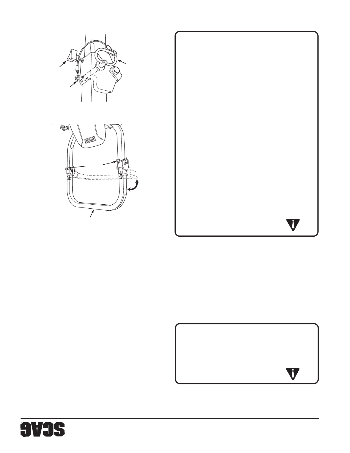
TENSIÓN
DE
PERILLA
AMARRE
PIN DE
Figura 2-2 Bisagra del ROPS
BLOQUEO
PIN DE
contra vuelco
7
Figura 2-1 Sistema plegable de protección
vuelco.
sobre su cabeza entre en contacto con la barra contra
NO permita que ningún objeto que se encuentre
entradas, etc.).
libre por encima de su cabeza (como ramas,
césped para comprobar que haya suficiente espacio
Revise el área cuidadosamente antes de cortar el
el espacio se lo permita.
Levante las barras contra vuelco tan pronto como
ni arranques o paradas.
Opere la máquina suavemente, sin giros repentinos,
la barra contra vuelco esté en posición alta.
SIEMPRE use el cinturón de seguridad cuando
DE TENSIÓN
PERILLAS
Y BLOQUEADA
POSICIÓN VERTICAL
retención.
2-2. Retire el cinturón de seguridad de los soportes de
horquillas y apriete las perillas de tensión. V ea la Figura
asegúrelos con los dos (2) pasadores de chaveta de las
6. Instale los dos (2) pines de bloqueo a través del agujero,
la posición vertical.
5. Para levantar la barra contra vuelco, suba la barra hasta
esté en la posición baja.
soportes de retención cuando la barra contra vuelco
El cinturón de seguridad sólo debe conectarse a los
retención como se muestra en la Figura 2-3, página 8.
4. Conecte el cinturón de seguridad a los soportes de
3. Baje la barra contra vuelco a la posición baja.
dos (2) pines de bloqueo. Vea la Figura 2-2.
2. Retire los pasadores de chaveta de las horquillas y los
la Figura 2-1.
ADVERTENCIA:
tensión en las barras del lado izquierdo y derecho. Vea
1. Para bajar la barra contra vuelco, afloje la perilla de
contra vuelco esté en posición baja.
NO use el cinturón de seguridad cuando la barra
absolutamente necesario.
Baje la barra contra vuelco solo cuando sea
contra vuelco está en posición baja.
No existe protección contra vuelco cuando la barra
ADVERTENCIA:
de esta pauta puede causar lesiones o la muerte.
sistema de protección contra vuelco. El incumplimiento
NO DEBE retirarse ninguno de los componentes del
control de dirección.
césped mojado. El césped mojado reduce la tracción y el
especialmente cuando el césped está mojado. No corte en
embargo, debe tener cuidado al viajar en cuestas,
y estabilidad bajo condiciones normales de corte. Sin
Este cortacésped se ha diseñado para tener buena tracción
ocasionar lesiones graves o la muerte.
durante la operación. No hacerlo así podría
cinturón de seguridad sujetado firmemente
posición levantada y bloqueada, y el
Mantenga la barra contra vuelco en
necesario.
Baje la barra contra vuelco solo cuando sea absolutamente
VUELCO
2.5 SISTEMA DE PROTECCIÓN CONTRA
Sección 2
Page 100
6
1 1. Corte sólo con luz de día o buena luz artificial.
de cruzar carreteras, caminos o caminos de grava.
10. Desconecte la potencia a la plataforma de corte antes
la visibilidad.
arbustos, árboles, u otros objetos que puedan disminuir
18. Tenga cuidado al aproximarse a esquinas ciegas,
remolque o un camión.
17. T enga cuidado al car gar o descar gar la máquina en un
daños.
corte y las partes móviles. El contacto puede causar
16. Mantenga las manos y pies lejos de las cuchillas de
causar la muerte.
Los gases de escape son peligrosos y podrían
un área encerrada sin ventilación apropiada.
NO opere el motor dentro de un edificio ni en
retroceder.
9. NO gire muy repentinamente. Tenga cuidado al
toda el área detrás del cortacésped.
absolutamente necesario y sólo después de observar
de retroceder. No corte en reversa a menos que sea
8. Desconecte la potencia a la plataforma de corte antes
ocultos.
a un área nueva. Preste atención a posibles peligros
tubos, raíces de árboles, etc.). Ingrese con precaución
bajas, etc.), y obstáculos subterráneos (aspersores,
obstrucciones presentes arriba de su cabeza (ramas
toda pendiente vertical. Tenga cuidado con las
peligros ocultos en el terreno. Manténgase alejado de
7. Preste atención a agujeros, piedras, raíces y otros
ADVERTENCIA:
quitar la materia atascada.
descarga. Use un palo u otro objeto para
NO use la mano para desatascar la tolva de
causar una quemadura.
estar lo suficientemente calientes como para
después de detenerlo. Estas zonas pueden
motor está funcionando, ni inmediatamente
NO toque el motor ni el silenciador mientras el
PRECAUCIÓN:
ADVERTENCIA:
todo movimiento antes de quitar la obstrucción.
motor, quite la llave de encendido, y espere que cese
6. Si la descarga del cortacésped se tapona, apague el
Sección 2
antes de reiniciar y operar la máquina.
de golpear un objeto extraño; el daño debe repararse
inspeccionarse para ver si han sufrido daños después
15. La máquina y los accesorios deben detenerse e
transporte o cuando no esté usándolos.
14. Desconecte la potencia a los accesorios cuando los
detener el motor, y quitar la llave.
los accesorios, poner el freno de estacionamiento,
sin atención, como desconectar el cortacésped, bajar
13. T ome toda precaución posible cuando deje la máquina
conectadas.
12. NUNCA levante la plataforma con las cuchillas
estacionamiento.
en la posición neutral y accione el freno de
de corte, coloque las palancas de control de dirección
en el asiento, desconecte la potencia a la plataforma
5. Antes de tratar de arrancar el motor, con el operador
funcionamiento.
que haya nadie cerca a la máquina mientras está en
descarga del material hacia otras personas, ni permita
4. Cuando use cualquier accesorio, nunca dirija la
desplácese a baja velocidad.
deténgase suavemente, evite giros innecesarios y
3. Para evitar volcarse o perder el control, arranque y
(CONTINUACIÓN)
2.4 CONSIDERACIONES DE OPERACIÓN
 Loading...