

Briggs & Stratton IS3200ZBVE3761, IS3200ZBV3272, IS3200ZKAV3572, IS3200Z, IS3200ZBV3261 Dealer Setup & Adjustment Instructions Manual
...
Not for
Reproduction

Not for
Reproduction
Quick Setup List
Setup Procedures
Uncrate the unit.
Connect the battery cables.
Install the ground speed control levers.
Install the seat.
Assemble the roll bar retainer pins.
Install the roll bar on the unit.
Install the roll bar safety decals (export models only).
Check engine oil level.
Check / Fill transmission oil level.
Check tire pressures.
Check mower blade bolt torque.
Install the mower deck pusher bars (72" Export Mower Decks)
Install the mower deck (72" Export Mower Decks)
Install the discharge chute (72" Export Mower Decks)
Install the mower deck drive belt (72" Export Mower Decks)
Check the deck lift rod timing.
Check and level the mower deck.
Check the mower deck drive belt.
Lubricate all grease and oil points.
Check / Add fuel.
Start the engine
PERFORM THE SAFETY CHECKS
Check forLOOSE HARDWARE.
Check allOPERATOR CONTROLS.
PerformSAFETY INTERLOCK SYSTEM CHECK.
Register Product
To register the product: log ontowww.thepowerportal.com, select the appropriate brand, click “Sales &
Marketing”, select the “Product Registration” link, and then select “New Product Registration”. Fill out and submit
the online product registration form.
Ferris is a registered trademark of Briggs & Stratton
Corporation.
2 ferrismowers.com
Not for
Reproduction
Setup Procedures
The items in this section provide the information necessary
to fully assemble, test, and prepare the unit, that these
instructions were included with, for delivery to your customer.
1. To raise the seat plate, release the latch by moving the
seat latch (A, Figure2) towards the front of the unit and
then raise the seat plate.
The Quick Setup List provided on page 2 of this booklet
to help you identify and check that the items have been
performed.
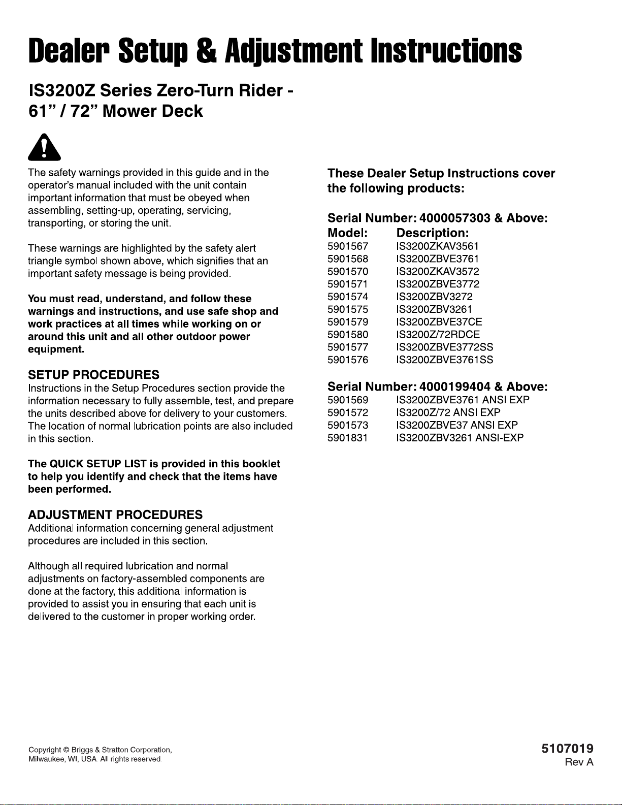
Uncrating
1. Locate the hydraulic actuators (A, Figure 1) on the side of
the unit's transmissions. There is one hydraulic actuator
on each transmission. The hydraulic actuator opens and
closes the transmission bypass valves.
1
2
2. The seat latch is spring loaded. When the seat plate is
lowered back into place the seat latch will lock the seat
plate into place.
2. To open the transmission bypass valves rotate
the hydraulic actuator clockwise to the "bypass"
position" (marked "bypass" on the transmission) (B).
3. Push the parking brake lever down and forward to release
the parking brake.
4. Be sure there are no nails or sharp objects on the bottom
skid to puncture the zero-turn rider's tires. Roll the zeroturn rider forward off the bottom skid.
5. After moving the zero-turn rider, close the bypass valves
by rotating the hydraulic actuator counter-clockwise to
the "run" position (marked "run" on the transmission) (C).
Connect the Battery Cables
WARNING
Battery acid can cause severe burns. Wear protective
gear when handling the battery.
Open flames and sparks can cause battery to explode.
BATTERY SAFETY RULES:
• Battery acid causes severe burns. Avoid contact with
skin.
• Wear eye protection when handling the battery.
• To avoid an explosion, keep flames and sparks away
from the battery, especially while charging.
• When installing the battery cables, connect the
positive (+) cable first and negative (-) cable last.
If not done in this order, the positive terminal can be
shorted to the frame by a tool.
1. Connect the red positive battery cable (A, Figure 3) to the
positive battery post.
Note:Both hydraulic actuators must be in the same position.
Operating the Seat Latch
Some models are equipped with a seat latch that secures the
seat plate in place. The seat latch is located by the left rear
corner of the seat plate.
3

Not for
Reproduction
3
2. Connect the black negative battery cable (B) to the
negative battery post.
Install the Ground Speed Control Levers
This procedure is only necessary if the ground speed control
levers are not factory-installed on your unit.
There is a LEFT-HAND (A, Figure 4) and a RIGHT-HAND
(B) control lever. When assembled to the base (C), the lever
base (D) should be pointing toward the rear of the machine as
shown in Figure 4.
Install the Seat
This procedure is only necessary if the seat is not factoryinstalled on your unit.
Some models are equipped with two sets of holes in the
seat plate that the seat can be installed in. Use the forward
set of holes to position the operator closer to the front of the
machine and the rear set of holes to position the operator
towards the rear of the machine. Determining what holes
to use is based on the preferred operating position of the
operator.
1. Unpack the seat.
2. Install the seat (A, Figure 5) onto the seat mount plate (B)
and secure with the 5/16 nylock flange nuts (C).
5
4
1. Remove the ground speed control levers and mounting
hardware from the handle bar box.
2. Install the ground speed control levers (A & B) onto the
control lever base using the hardware (E) supplied in the
box. Prior to tightening the bolts, align the handles with
each other.
3. Connect the wire harness (D) to the seat switch (E) that is
located in the bottom of the seat.
Assemble the Roll Bar Retainer Pins
1. Unpack the roll bar and hardware from the box.
2. Lock the snap end (A, Figure 6) of the lanyard (B) through
the retainer pin handle (C) and snap together.
6
4 ferrismowers.com
Not for
Reproduction
3. Install the lanyard anchor (D) onto the lanyard.
4. Install the hair pin (E) onto the loop end (F) of the lanyard
as shown in Figure 6.
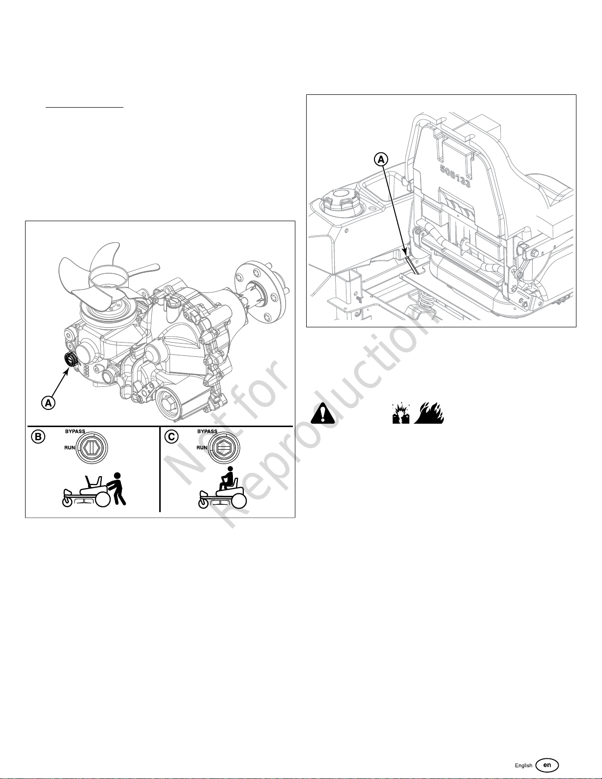
Install the Roll Bar to the Unit
The roll bar assembly is installed in the roll bar pockets which
are part of the main frame of the unit and are located behind
the seat and in front of the engine on both sides of the unit.
1. Assemble the top loop (A, Figure 7) to the left upright
tube (B) and the right upright tube (C) by loosely installing
the 1/2 bolt (D), a 1/2 washer (E) through the retainer pin
assembly (F), then through the hole in the top loop that is
closest to the rear of the machine, the upright tube, and
then loosely install the 1/2 hex lock nut (G).
7
8
2. Fold the roll bar to the down position (A, Figure 8) and
lock in place using the retainer pins and hair pin clips (B).
3. Make sure that no fuel lines, cables, or parts of the wire
harness are in the way of the roll bar pockets.
4. From the bottom of the roll bar upright tube measure up
8” (H, Figure 7) and mark the distance with a marking tool
or a piece of tape. Repeat for other upright tube.
5. Install the roll bar into the roll bar pockets. The roll bar is
installed so that the safety decals are on the left side of
the machine (as determined from the operator’s position)
facing towards the front of the machine. When the mark
you made is even with the top of the roll bar pocket, the
holes are close to being lined up. If necessary, use a
dead blow hammer and drift pin to assist in lining up the
holes in the roll bar with the holes in the roll bar pocket.
6. Jack up the rear of the zero-turn rider and secure with
jack stands.
7. Remove the rear tires from the unit.
8. Loosely install four (4) 1/2" X 3" bolts (C, Figure 8) and
1/2" washers (D) through the frame of the unit, the roll
bar, and loosely install the 1/2" hex lock nuts (E).
9. Tighten the 1/2” hardware that secures the upright tubes
to the frame of the unit to 82 ft. lbs (108 Nm) of torque.
10. Tighten the 1/2” bolt and hex lock nuts that secure the
top loop to the upright tubes. Do not over-tighten. The top
loop should pivot snugly with the retainer pins removed.
11. Re-install the rear tires to the machine. The lug nuts
should be torqued to 90 ft. lbs. (122 Nm). Remove the
jack stands from underneath the zero-turn rider.
12. Raise the top loop to the upright position and install the
retainer pins and hair pin clips to secure the roll bar in the
raised position.
5
Not for
Reproduction
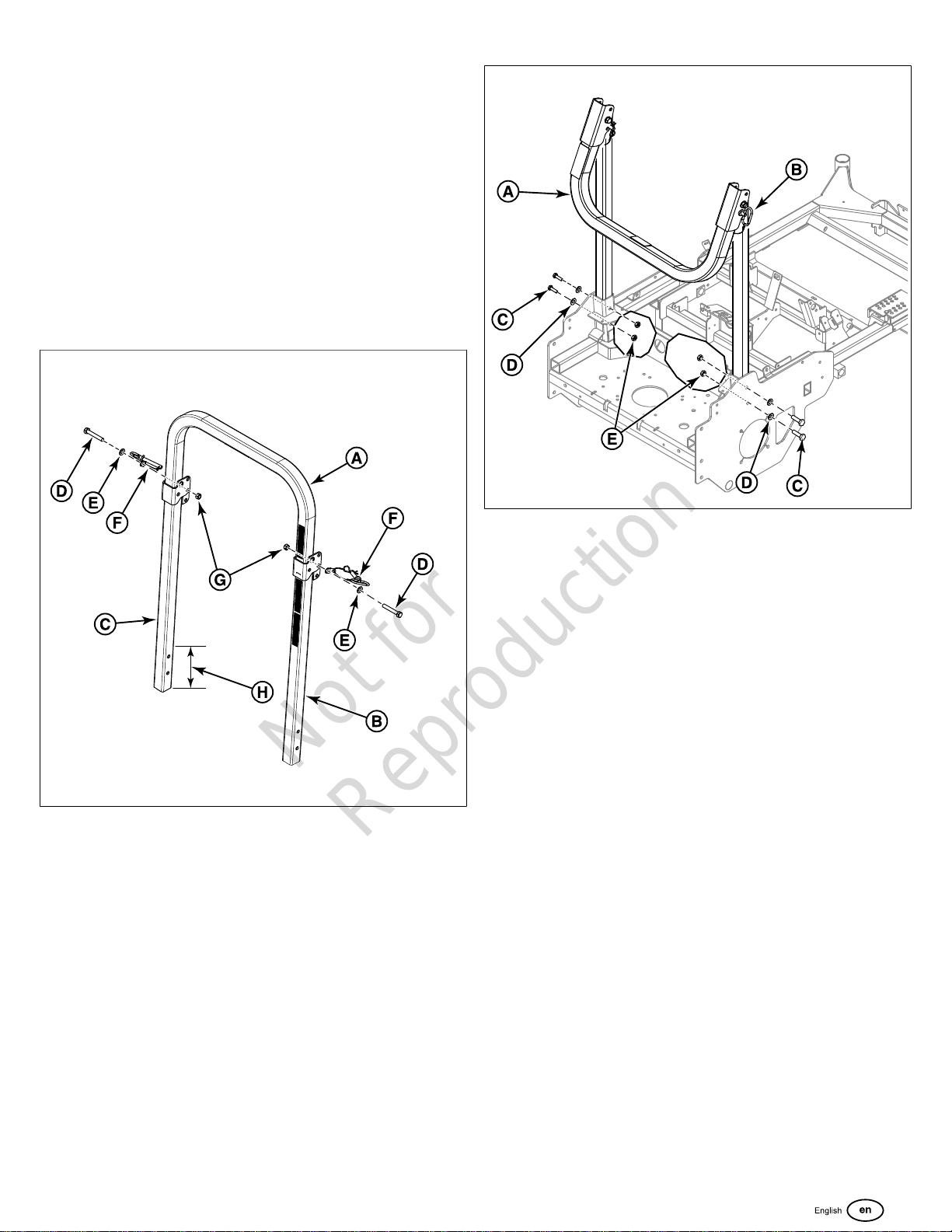
Install the Roll Bar Safety Decals (Export
Models Only)
1. Remove the black and yellow CE safety decals (A, & B,
Figure 9) from the publications packet.
9
2. Remove the three (3) existing English language decals
(C) from the roll bar.
3. Refer to Figure 9 for decal installation locations. The long
decal, part number 5100536 (A) is installed below the
roll bar pivot of the roll bar. The short decal, part number
5100537 (B), is installed above the roll bar pivot.
Check the Engine Oil Level (Engines
with Remote Oil Tank)
Some models in this series of mower feature a remote oil tank
(A, Figure 10) that supplies oil to the engine.
10
11
2. Use the dipstick to check the engine oil level. Maximum
oil level is the “FULL” line (C) on the dipstick. If the oil
level is at the “ADD 1 QT.” line (D) or below, more oil
must be added.
3. If necessary, open the oil fill cover and slowly add
15W-50 synthetic oil. (See the engine oil operator’s
manual for other oil recommendations.) The remote oil
tank is designed to hold 5 qt (4,73 L) of engine oil.
4. Wipe the engine oil dipstick with a clean cloth and then
install it into the tank by pressing down firmly with your
hand. The engine oil dipstick has a detent (E) and it must
snap into place on the lip (F) of the tank housing so that
the dipstick is fully installed into the tank. This action
requires moderate force.
5. Close the oil fill cover.
6. If desired, a new self-locking tie can be installed to keep
the oil fill cover securely closed.
Check the Engine Oil Level (All Other
Engine Options)
Some models in this series of mower feature a Kawasaki
FX1000V engine (A, Figure 12). Refer to Figure 12 for the
location of components used in this procedure.
12
1. Clean the area around the engine oil dipstick (A, Figure
11) and oil fill cover (B) to remove any debris.
6 ferrismowers.com
Not for
Reproduction
1. Clean the area around the engine oil dipstick (B) to
remove any debris.
2. Use the engine oil dipstick to check the engine oil level.
If necessary, add engine oil through the engine oil fill (C).
Check the engine manufacturer's owner's manual for oil
recommendations.
3. Wipe the dipstick with a clean cloth and then re-install it.
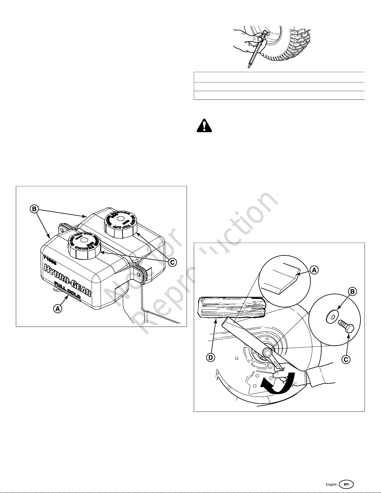
Check / Fill Transmission Oil Level
This unit is equipped with two transmission oil tanks. One
transmission oil tank only supplies oil to one transmission.
The level of oil in both transmission tanks must be checked,
and if necessary, filled.
Oil Type: SAE 20W-50 motor oil
1. Locate the transmission oil tanks (B, Figure 13) by raising
the seat plate of the unit.
2. Check the oil level when the unit is cold. The oil should be
up to the "FULL COLD" mark (A) on the transmission oil
tanks (B). If the oil is below this level, proceed to step #3.
13
Tire Pressure
Front 25 psi (1,72 bar)
Rear 15 psi (1,03 bar)
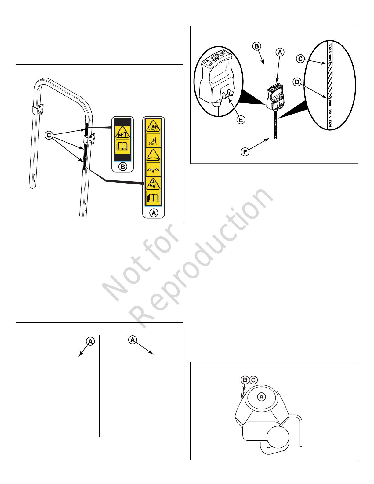
Check the Mower Blade Bolt Torque
WARNING
Avoid injury! Mower blades are sharp.
• Mower blades are sharp. For your personal safety, do
NOT handle mower blades with bare hands.
• Careless or improper handling of blades may result in
serious injury.
• Blade mounting bolts must each be installed with a
flat washer and then securely tightened. Torque blade
mounting bolts to 120 ft. lbs. (163 Nm).
1. Lock the mower deck in it's highest cutting position.
2. Check that the blades are installed with the tabs
pointing up (A, Figure14)towards the deck as showing
inFigure14.
3. Before removing the tank cap (C), make sure that the
area around the tank cap and fill neck of the tank is free
of dust, dirt, and other debris. Remove the tank caps.
4. Add oil up to the "FULL COLD" mark.
5. Re-install the tank cap.
6. After adding oil to the tanks, it may be necessary to purge
air from the hydraulic system. If the unit is not driving
properly perform the Purging the Air from the Hydraulic
System procedure.
Check Tire Pressures
Tire pressure should be checked periodically, and maintained
at the levels shown in the chart. Note that these pressures
may differ slightly from the "Max Inflation" stamped on the
side-wall of the tires. The pressures shown in the chart
provide proper traction and extend tire life.
14
3. Check that a flat washer (B) is installed between each
blade and the head of it's mounting bolt (C).
4. Wedge a wooden block (D) between the mower blade
and the mower deck housing to keep the mower blade
from turning. Torque each mower blade mounting bolt to
120 ft. lbs. (163 Nm).
7

Not for
Reproduction
Install the Pusher Bars (72" Export
Models)
There is a left-hand (A, Figure 15) and a right-hand pusher
bar (B).
15
1. Measure the pusher bar length from the outside of
the cross tube to the center of the ball joint (C). The
measurement should be 16-9/16” (42.1 cm).
2. If the measurement does not equal 16-9/16” (42.1 cm),
loosen the jam nut and turn the ball joint until it the
measurement of 16-9/16” (42.1 cm) is achieved. Tighten
the jam nut.
3. There are four plastic bushings (D) installed in the cross
tube, two on each end. Make sure that all four of the
plastic bushings are still installed in the cross tube.
4. Holding the pusher bar in place, insert the mount pin (E)
through the mower decks mounting brackets and the
pusher bar.
5. Secure the mount pin to the mower deck bracket with the
3/8-16 X 1” bolt (F), 3/8 SAE washers (G), and 3/8 hex
nylock flange nut (H) that are provided.
6. Secure the other end of the mount pin in place by
installing a 3/8-16 X 1” bolt (I) and .390 X 1.50 X .109
washer (J) into the internal threads of the mount pin.
7. Repeat the process to install the right-hand pusher bar to
the mower deck.
4. Fasten the ball joints of the pusher bars (A, Figure 16) to
the transmission cradle (B) using the 3/4-16 X 3” bolt (C),
3/4 flat washer (D), 3/4 rod end seal (E), and the 3/4 hex
nylon nut (F).
16
5. Place 2 X 4 blocks (B, Figure 17) underneath each corner
of the mower deck with the 3-1/2” sides being vertical.
See Figure 17. The arrow (A) indicates the front of the
mower deck.
17
6. Install the spacer (A, Figure 18) into the eyelit of the deck
linkage (B).
Install the Mower Deck (72" Export
Models)
1. Park the zero-turn rider on a flat, level surface. Engage
the parking brake, turn the ignition switch to OFF, and
remove the key.
2. Lock the deck lift pedal in the TRANSPORT position.
Place the deck height adjustment pin in the 4” (10.2
cm) position and lower the deck lift pedal until the arm
contacts the pin. Secure in place if necessary.
3. Center the mower deck underneath the zero-turn rider’s
frame.
8 ferrismowers.com
 Loading...