

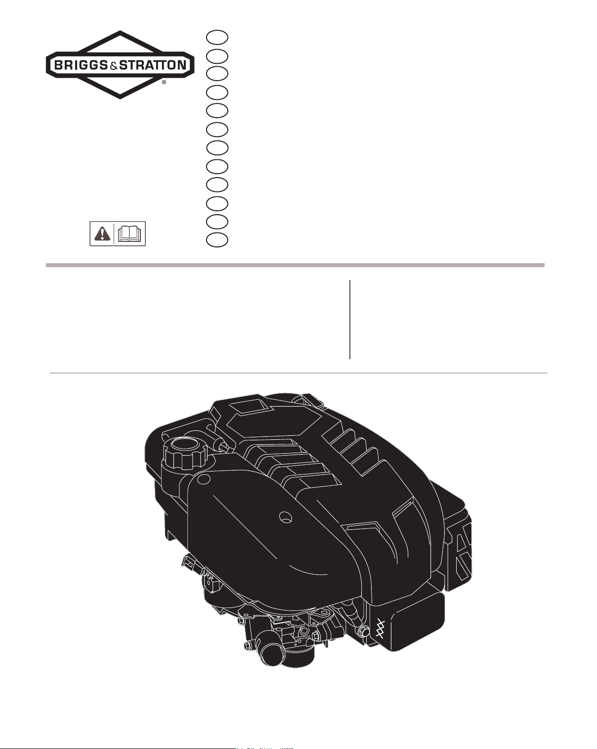
Briggs & Stratton Intek 825 Series, Intek 850 Series, Intek 875 Series, Intek Edge 825 Series, Intek Edge 850 Series Operating And Maintenance Instructions Manual
...
GB
Operating & Maintenance Instructions
BG
Инструкции за работа и техническо обслужване
CR
Upute za koričtenje i odrďavanje
CZ
Návod k obsluze a údrďbì
EE
Kasutus− ja hooldusjuhend
H
Kezelési és karbantartási útmutató
LT
Naudojimo ir aptarnavimo instrukcija
LV
LietoĠanas un apkopes instrukcija
PL
Instrukcja Obs³ugi i Konserwacji
RO
Instrucþiuni de utilizare ºi de întreþinere
RU
Инструкции по эксплуатации и техническому обслуживанию
SL
Navodila za uporabo & vzdrďevanje
Model 120000
Intek 825/850 /875 Series
Intek Edge 825/850 Series
Intek Pro 825 Series
BRIGGSandSTRATTON.com
E Copyright Briggs & Stratton Corporation
Milwaukee, Wisconsin 53201 U.S.A.
Form No. MS-3784-3/07
Printed in U.S.A.

Fig. 1
8
7
6
9
1
10
Fig. 2
Fig. 3
Fig. 4
5
-20 0
°F
-30
°C
Ê
4
20 40 60 80 100
-20 -10 0 10 20 30 40
3
**
*
32
Ì
2
Í
Ë
12
11
Î
Ê
Ì
Ë
Ï
0.15
LITERS
Ê
Ë
Ì
Fig. 5 Fig. 6
Ê
Ë
Ë
Ì
Ê
Ì
Ë
Ì
Note: (This note applies only to engines used in the U.S.A.) Maintenance, replacement or repair of the emission control devices and systems may be performed
by any nonroad engine repair establishment or individual. However, to obtain no charge repairs under the terms and provisions of the Briggs & Stratton
warranty statement, any service or emission control part repair or replacement must be performed by a factory authorized dealer.
GB
ENGINE COMPONENTS
Fig. 1
2
Resistor spark plug
3
Carburetor
4
Primer bulb, if equipped
5
Choke lever, if equipped
6
Air cleaner
7
Fuel fill
8
Rope handle
9
Finger guard
10
Oil fill/Dipstick
11
Muffler guard
12
Muffler/spark arrester, if equipped
Record your engine
future use.
Record your date of purchase here for future use.
1
Engine Model Type Code
xxxxxx xxxx xx xxxxxxxx
Model, Type and Code numbers here for
TECHNICAL INFORMATION
TUNE-UP SPECIFICATIONS
Armature air gap 0.25 − 0.36 mm . . . . . . . . . . . . .
Spark plug gap 0.51 mm (0.20 in.). . . . . . . . . . . .
Valve clearance with valve springs installed and piston 6
mm past top dead center (check when engine is cold).
See Repair Manual P/N 272147.
Intake valve clearance 0.10 − 0.20 mm . . . . . . . . .
Exhaust valve clearance 0.10 − 0.20 mm . . . . . . .
Note: Engine power will decrease 3-1/2% for each
1,000 feet (300 meters) above sea level and 1%
for each 10° F (5.6° C) above 77° F (25° C). It
will operate satisfactorily at an angle up to 15°
Refer to the equipment operator manual for safe
allowable operating limits on slopes.
(0.010 − 0.014 in.). . . . . . . . . . . . . . . . . . . . . . . . .
(0.004 − 0.008 in.). . . . . . . . . . . . . . . . . . . . . . . . .
(0.004 − 0.008 in.). . . . . . . . . . . . . . . . . . . . . . . . .
SAFETY SPECIFICATIONS
BEFORE OPERATING
ENGINE
• Read entire Operating & Maintenance Instructions AND
the instructions for the equipment this engine powers.*
• Failure to follow instructions could result in serious
injury or death.
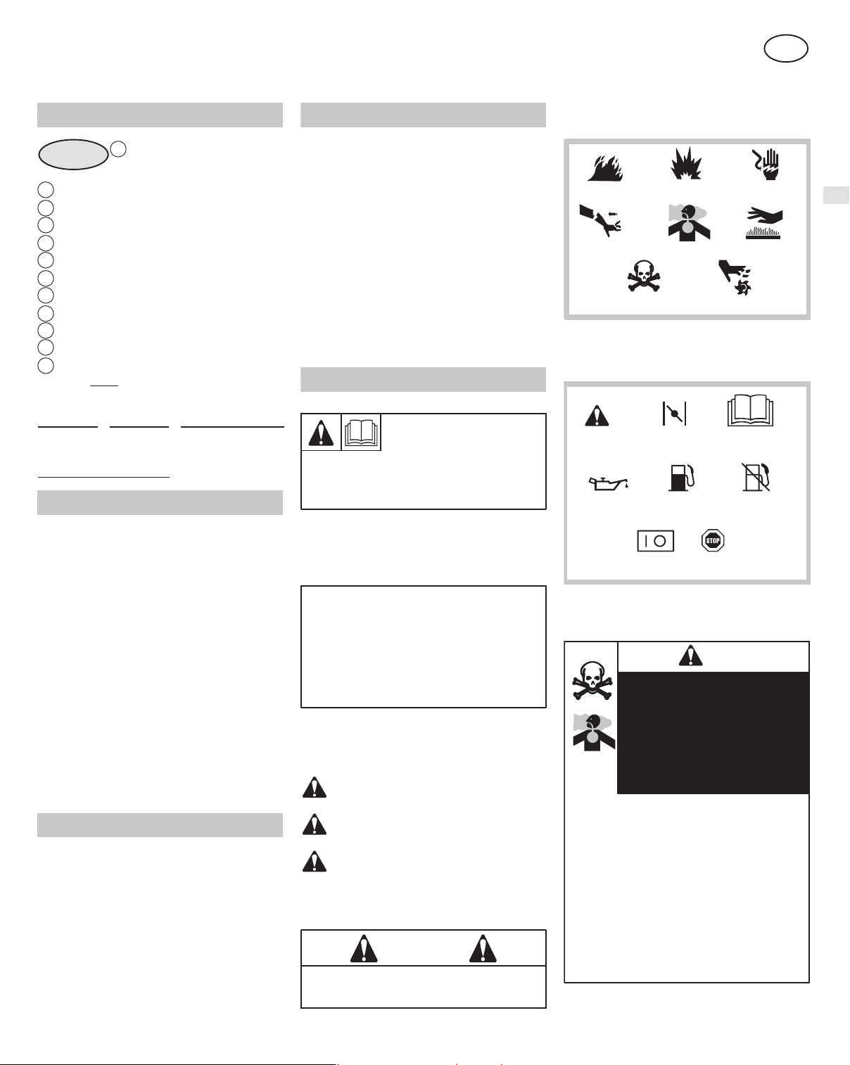
Hazard Symbols and Meanings
Fire
Hazardous Chemical
.
Explosion
Toxic Fu mes
International Symbols and Meanings
ChokeSafety Alert
Oil
Fuel
Shock
Hot SurfaceKickback
Moving Parts
Read Operator’s
Manual
Fuel Shutoff
Engine Power Rating Information
The gross power rating for individual gas engine models is
labeled in accordance with SAE (Society of Automotive
Engineers) code J1940 (Small Engine Power & Torque
Rating Procedure), and rating performance has been
obtained and corrected in accordance with SAE J1995
(Revision 2002-05). Torque values are derived at 3060
RPM; horsepower values are derived at 3600 RPM. Actual
gross engine power will be lower and is affected by, among
other things, ambient operating conditions and engine-to-engine variability. Given both the wide array of products on
which engines are placed and the variety of environmental
issues applicable to operating the equipment, the gas
engine will not develop the rated gross power when used in
a given piece of power equipment (actual on-site" or net
power). This difference is due to a variety of factors
including, but not limited to, accessories (air cleaner,
exhaust, charging, cooling, carburetor, fuel pump, etc.),
application limitations, ambient operating conditions
(temperature, humidity, altitude), and engine-to-engine
variability. Due to manufacturing and capacity limitations,
Briggs & Stratton may substitute an engine of higher rated
power for this Series engine.
GENERAL INFORMATION
In the state of California, OHV Model 120000 engines are
certified by the California Air Resources Board to meet
emissions standards for 125 hours. Such certification does not
grant the purchaser, owner or operator of this engine any
additional warranties with respect to the performance or
operational life of this engine. This engine is warranted solely
according to the product and emissions warranties stated
elsewhere in this manual.
Model 120000
Bore 68.26 mm (2.69 in.). . . . . . . . . . . . . . . . . . . .
Stroke 52.00 mm (2.05 in.). . . . . . . . . . . . . . . . . .
Displacement 190 cc (11.58 cu. in.). . . . . . . . . . . .
* Briggs & Stratton does not necessarily know what equip-
ment this engine will power. For that reason, you should
carefully read and understand the operating instructions for
the equipment on which your engine is placed.
THE OPERATING &
MAINTENANCE INSTRUCTIONS
CONTAIN SAFETY
INFORMATION TO:
• Make you aware of hazards associated with engines
• Inform you of the risk of injury associated with those
hazards, and
• Tell you how to avoid or reduce the risk of injury.
A signal word (DANGER, WARNING, or CAUTION) is used
with the alert symbol to indicate the likelihood and the potential
severity of injury. In addition, a hazard symbol may be used to
represent the type of hazard.
DANGER indicates a hazard which, if not avoided,
will result in death or serious injury.
WARNING indicates a hazard which, if not avoided,
could result in death or serious injury.
CAUTION indicates a hazard which, if not avoided,
might result in minor or moderate injury.
, when used without the alert symbol,
CAUTION
indicates a situation that could result in damage to
the engine.
WARNING
The engine exhaust from this product contains chemicals
known to the State of California to cause cancer, birth
defects, or other reproductive harm.
1
On Off
Stop
DANGER
Contents are HARMFUL OR FATAL IF
SWALLOWED. Avoid contact to eyes,
skin, or clothing. Do not take internally.
Avoid breathing the mist or vapor.
Overexposure to eyes or skin can cause
irritation. Keep stabilizer out of the reach
of children.
Fuel stabilizer is a hazardous chemical.**
• Fresh Start™ fuel cap is designed to hold a
cartridge which contains fuel stabilizer.
• IF SWALLOWED, call physician immediately.
Do not induce vomiting. If inhaled, remove to
fresh air. In case of eye or skin contact, flush
with water for 15 minutes.
• Store unopened cartridges in a cool, dry,
well-ventilated area. Keep open cartridge in
fuel cap, and fuel cap closed on fuel tank when
not in use.
** Fuel stabilizer contains 2,6-di-tert-butylphenol
(128-39-2) and aliphatic petroleum distillate
(64742-47-8).
 Loading...