

Briggs & Stratton FW25KAV1548, FW25CCKAV1548, FW25CCKAV1952, FW25KAV1952, FW25CCKAV1948 Setup Instructions
...Page 1
Not for
Reproduction
Page 2

Not for
Reproduction
Quick Setup List
Setup Procedures
Uncrate the unit.
Connect the battery cables to the battery (Electric Start Models Only)
Check the engine oil level.
Check / Fill transmission oil level.
Check tire pressures.
Check mower blade bolt torque.
Check and level the mower deck.
Check the mower deck drive belt.
Lubricate all grease and oil points.
Check / Add fuel.
Start the engine
PERFORM THE SAFETY CHECKS
Check for LOOSE HARDWARE.
Check all OPERATOR CONTROLS.
Perform SAFETY INTERLOCK SYSTEM CHECK.
Register Product
To register the product: log onto www.thepowerportal.com, select the appropriate brand, click “My Resources,”
select the “Product Registration and Rebate” icon and then the “New Product Registration / Rebate” tab. Fill out
and submit the online product registration form.
FERRIS and SNAPPER PRO are registered trademarks of
Briggs & Stratton Corporation.
Ferris
5375 N. Main Street
Munnsville, NY, 13409-4003
(800) 933-6175
ferrismowers.com
Snapper Pro
5375 N. Main Street
Munnsville, NY, 13409-4003
(800) 933-6175
snapperpro.com
2 ferrismowers.com | snapperpro.com
Page 3
Not for
Reproduction
Setup Procedures
The items in this section provide the information necessary to
fully assemble, test, and prepare the unit, that these instructions
were included with, for delivery to your customer.
The Quick Setup List provided on page 2 of this booklet to
help you identify and check that the items have been
performed.
Uncrating
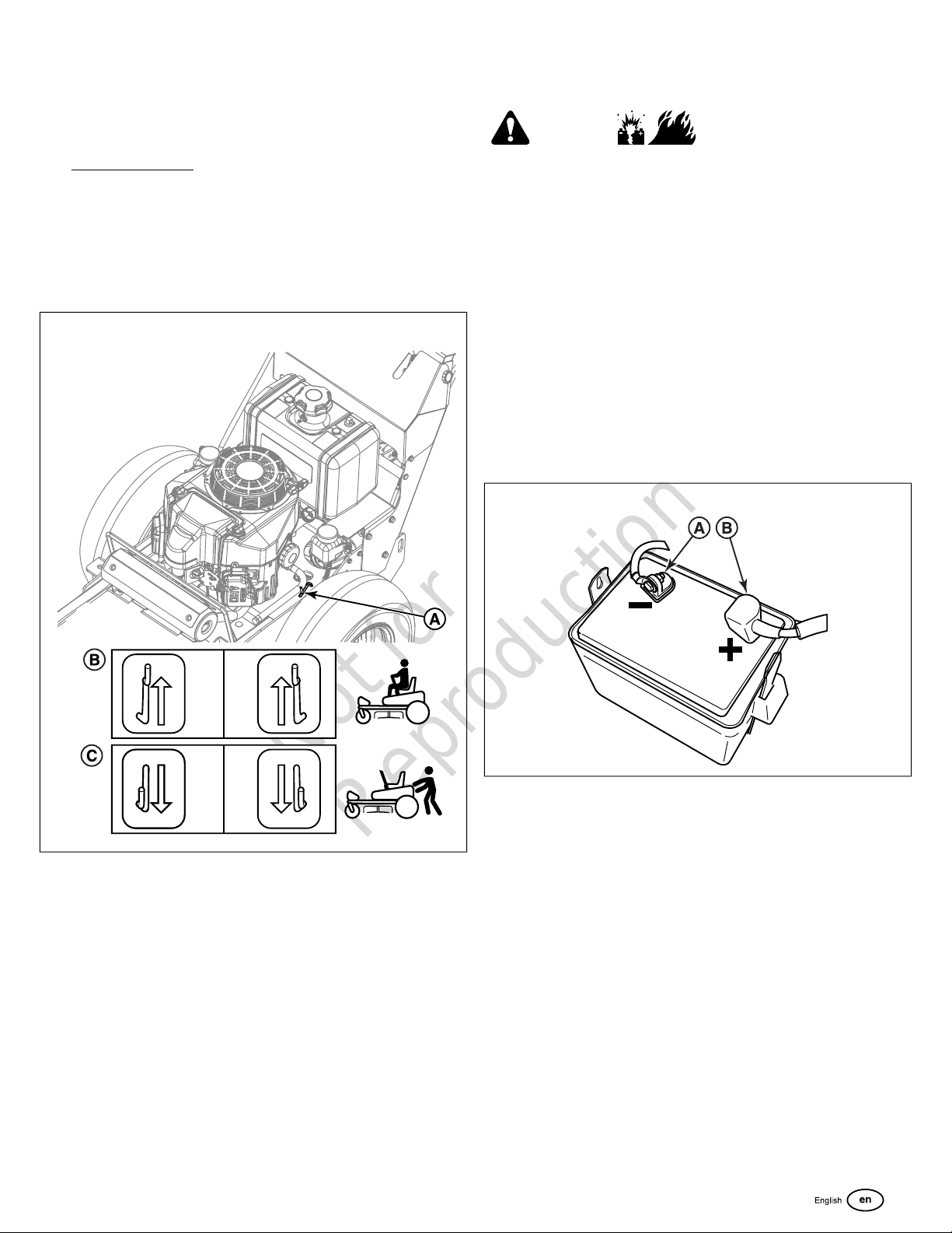
1. Locate the transmission release levers (A, Figure 1) by the
rear wheels of the unit.
1
Connect the Battery Cables to the Battery
(Electric Start Models Only)
WARNING
Battery acid can cause severe burns. Wear protective
gear when handling the battery.
Open flames and sparks can cause battery to explode.
BATTERY SAFETY RULES:
• Battery acid causes severe burns. Avoid contact with skin.
• Wear eye protection when handling the battery.
• To avoid an explosion, keep flames and sparks away from
the battery, especially while charging.
• When installing the battery cables, connect the positive
(+) cable first and negative (-) cable last. If not done in
this order, the positive terminal can be shorted to the
frame by a tool.
1. Connect the red positive battery cable (B, Figure 2) to the
positive battery post.
2
2. To disengage the transmissions (free-wheel position), pull
both transmission release levers back and out so that they
lock in the disengaged (free-wheel position)(C).
3. Disengage the parking brake.
4. Be sure there are no sharp objects on the bottom skid to
puncture the unit’s tires. Roll the unit forward off of the
bottom skid.
5. After moving the unit, re-engage the transmissions (drive
position) by pulling the transmission release levers rearward
and inward to release them from the disengaged position
and then allow them to move forward to the engaged (drive)
position (B).
2. Connect the black negative battery cable (A) to the negative
battery post.
Check the Engine Oil Level
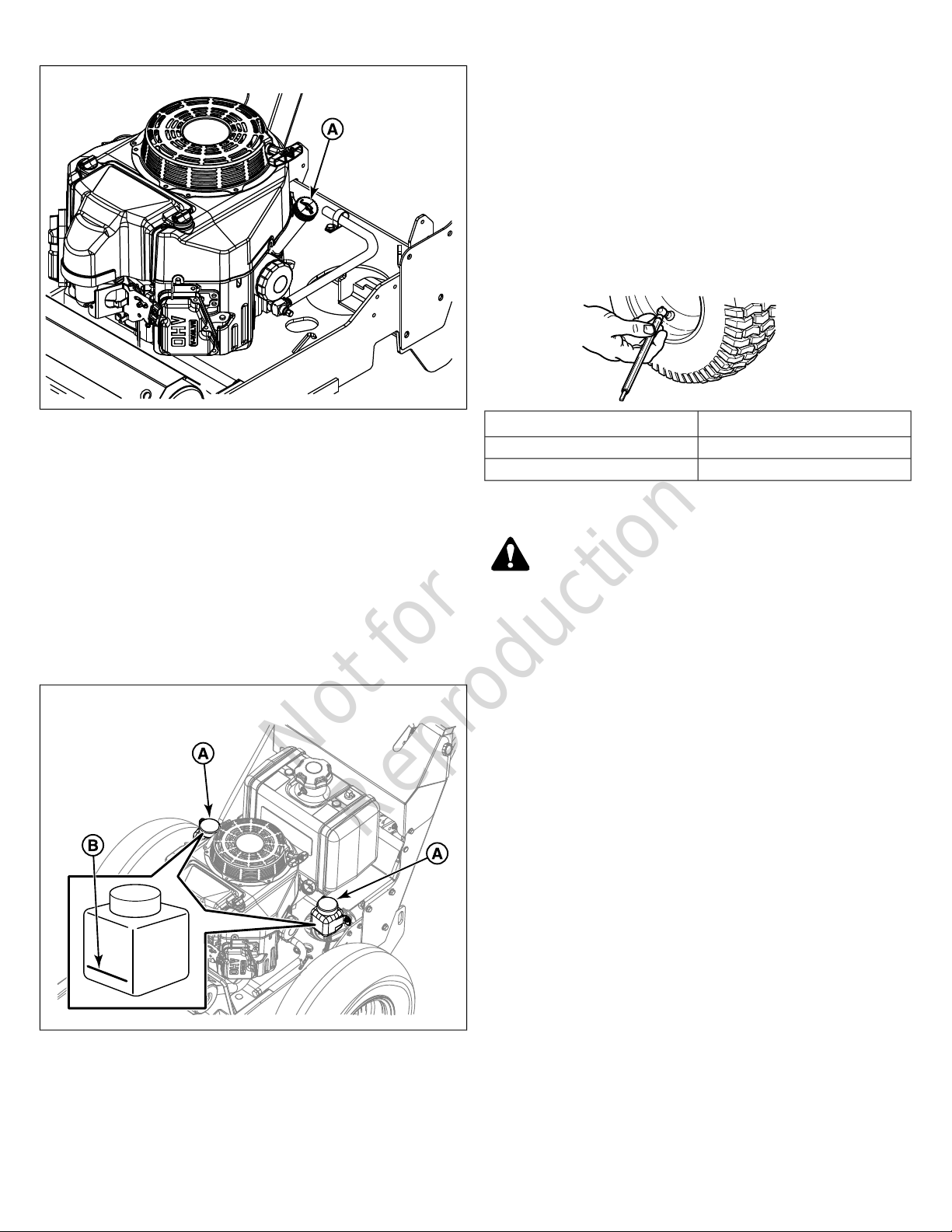
1. Use the dipstick (A, Figure 3) to check the engine oil level.
If necessary add engine oil. Check the engine manufacturers
owner’s manual for the oil recommendations.
3
Page 4
Not for
Reproduction
3
Check / Fill Transmission Oil Level
This unit is equipped with two transmission oil tanks. One
transmission oil tank supplies oil to one transmission. The level
of oil in both transmission tanks must be checked, and if
necessary, filled.
Oil Type: 20W-50 conventional detergent motor oil.
1. Locate the transmission oil tanks (A, Figure 4) positioned
by the fuel tank assembly.
2. Check the oil level when the unit is cold. The oil should be
up to the “FULL COLD” mark (B). If the oil is below this
level, proceed to step #3.
4
6. After adding oil to the tanks, it may be necessary to purge
air from the hydraulic system. If the unit is not driving
properly perform the
System
procedure.
Purging the Air from the Hydraulic
Check Tire Pressures
Tire pressure should be checked periodically, and maintained
at the levels shown in the chart. Note that these pressures may
differ slightly from the "Max Inflation" stamped on the side-wall
of the tires. The pressures shown in the chart provide proper
traction and extend tire life.
PressureTire
N/A (flat free tire)Front
15 psi (1,03 bar)Rear
Check Mower Blade Bolt Torque
WARNING
Avoid injury! Mower blades are sharp.
• Mower blades are sharp. For your personal safety, do
NOT handle mower blades with bare hands.
• Careless or improper handling of blades may result in
serious injury.
• Blade mounting bolts must each be installed with a flat
washer and then securely tightened. Torque blade
mounting bolts to 120 ft. lbs. (163 Nm).
1. Raise the mower deck to it's highest cutting position.
2. Check that the blades are installed with the tabs pointing
up (A, Figure 5) towards the deck as showing in Figure 5.
3. Before removing the tank caps, make sure the area around
the tank cap and fill neck of the tank is free of dust, dirt, or
other debris. Remove the tank cap.
4. Add oil up to the “FULL COLD” mark (B).
5. Reinstall the tank caps.
4 ferrismowers.com | snapperpro.com
Page 5
Not for
Reproduction
5
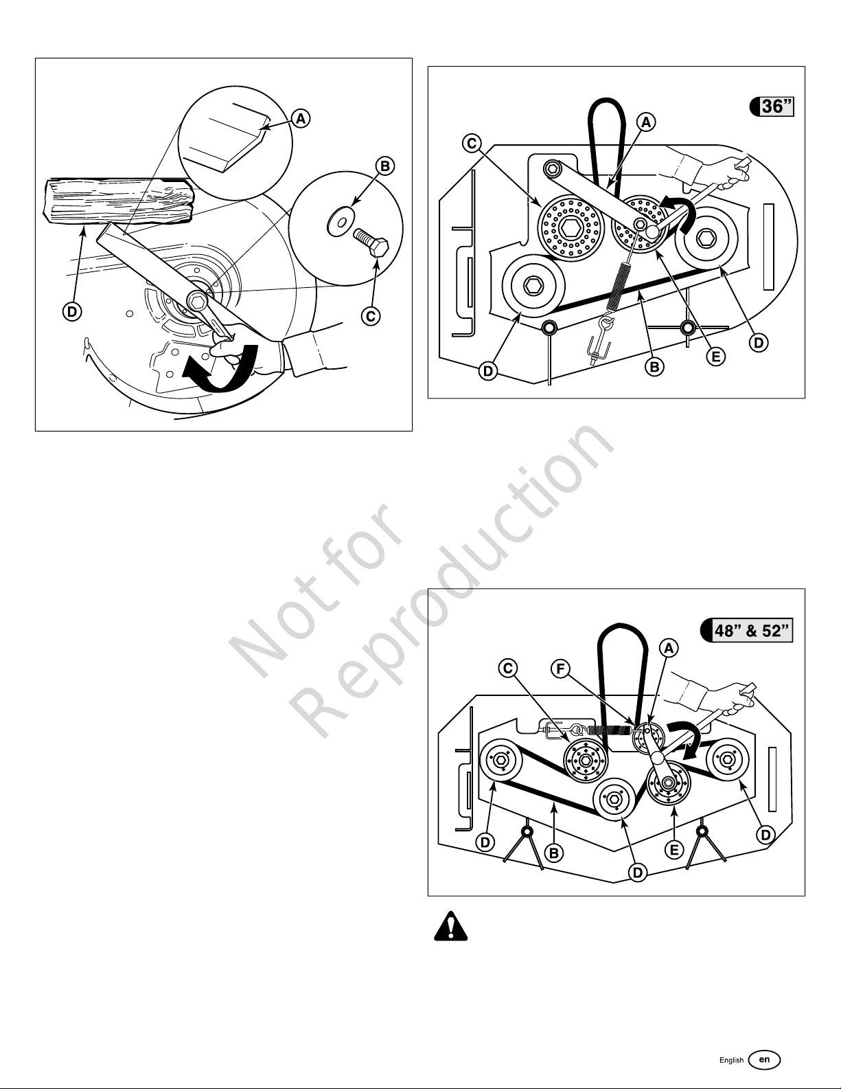
3. Check that a flat washer (B) is installed between each blade
and the head of it's mounting bolt (C).
4. Wedge a wooden block (D) between the mower blade and
the mower deck housing to keep the mower blade from
turning. Torque each mower blade mounting bolt to 120 ft.
lbs. (163 Nm).
6
• 48” & 52” Mower Decks: Make sure that the V-side
of the mower deck drive belt (B, Figure 7 & Figure 8)
runs in the pulley grooves of the spindle pulleys (D),
and the pulley grooves of the PTO clutch pulley and
that the back side of the belt contacts the front
stationary pulley (E), rear stationary pulley (C) and the
adjustable idler pulley (F).
48" Mower Deck - S/N: All & 52" Mower Decks - S/N:
2017243271 & Above
Check and Level the Mower Deck
The levelness of the mower deck is determined by how the
cutting height was set. See
cutting height adjustment procedure.
Cutting Height Adjustment
for the
Check the Mower Deck Drive Belt
NOTICE
pulleys.
1. Park the unit on a flat level surface such as a concrete floor.
Disengage the PTO, engage the parking brake, turn the
ignition switch to OFF and remove the key.
2. Lower the mower deck to its lowest cutting position and
remove the mower deck guards.
3.
36" Mower Decks
To avoid damaging belts, do not pry belts over
• 36” Mower Decks: Make sure that the V-side of the
mower deck drive belt (B, Figure 6) runs in the pulley
grooves of the spindle pulleys (D), and the pulley
grooves of the PTO clutch pulley and that the back side
of the belt contacts the rear stationary pulley (C) and
the adjustable idler pulley (E).
7
WARNING
Use extreme caution when rotating the idler arm with the
breaker bar due to the increased tension in the spring as the
idler arm is being rotated. Injury may result if the breaker bar
is prematurely released while the spring is under tension.
5
Page 6

Not for
Reproduction
4.
36” Mower Decks (S/N: All) & 52” Mower Decks (S/N:
•
2017243270 & Below): If the mower deck drive belt is
not properly seated, use a 1/2” breaker bar and place
the square end in the opening located in the end of the
idler arm (A, Figure 6 & Figure 8), and carefully rotate
the breaker bar counter-clockwise, which will relieve
the tension on the belt exerted from the idler arm.
52" Mower Decks - S/N: 2017243270 & Below
8
should equal the measurement as indicated in the chart. If
not, continue with step #4.
36" Mower Deck
9
• 48” Mower Decks (S/N: All) & 52” Mower Decks (S/N:
2017243271 & Above): If the mower deck drive belt is
not properly seated, use a 1/2” breaker bar and place
the square end in the opening located in the end of the
idler arm (A, Figure 7), and carefully rotate the breaker
bar clockwise, which will relieve the tension on the belt
exerted from the idler arm.
5. Re-seat the mower deck drive belt and carefully release
the tension on the breaker bar.
Check / Adjust the Mower Belt Idler Tensioning
Spring Length
Mower Deck Belt Idler Tensioning Spring Length
MeasurementSerial NumberDeck Size
6-3/4" (17,1 cm)2017555756 & Below36" Mower Deck
7" (17,8 cm)2017555757 & Above36" Mower Deck
6-1/8" (15,6 cm)All48" Mower Deck
6-3/4" (17,1 cm)2017243270 & Below52" Mower Deck
6-1/8" (15,6 cm)2017243271 & Above52" Mower Deck
48" Mower Deck
10
52" Mower Deck - S/N: 2017243270 & Below
1. Set the mower deck to the 3-1/2" (8.9 cm) cutting position.
2. Use the
chart to determine the correct spring length for your unit.
3. Measure the coil length (A, Figures 9, 10, 11, & 12) of the
mower belt idler tensioning spring (B). The measurement
Mower Deck Belt Idler Tensioning Spring Length
6 ferrismowers.com | snapperpro.com
Page 7

Not for
Reproduction
11
52" Mower Deck - S/N: 2017243271 & Above
12
Grease Fitting Location
serial number range 2017170234
& below only
Figure 14)
16, & 17)
Models: Units in serial number
range 2017170234 & below only;
52" Models: Units is serial number
range 2017243270 & below only
Lubricating the Front Casters) (A,
Figure 18)
Front Casters)
Not all greases are compatible. Red grease (p/n 5022285) is
recommended, automotive-type, high-temperature, lithium
grease may be used when this is not available.
(C)
Units in
48"
Qty of Fittings
(36" Models)
Qty of Fittings
(48" & 52"
Models)
2Drive Lever Pivots (B)
8Grease-able Ball Joints -
1Forward Speed Indicator Pivot (A,
1Transaxle Drive Idler Arm (B)
32Mower Deck Spindles (A, Figures 15,
1Mower Deck Idler Arm (B) -
2Front Caster Wheel Axles (See
(N/A)Front Casters (See Lubricating the
4. Loosen the jam nut (C) on the eye bolt (D).
5. Turn the adjustment nut (E) until the measurement as
indicated in the chart is achieved.
6. Re-tighten the jam nut.
7. Re-install the mower deck guards.
8. Run the mower under no-load condition for about five (5)
minutes to break in the new belt.
Oil Application Locations
Ball Joints Figure 13)
Operator Presence Flap Pivots (D)
Neutral Return Pedal Pivots (E)
Control Rod Pivots (F)
Parking Brake Handle Pivot (C, Figure 14)
Parking Brake Rod Pivots Points (D)
Lower Parking Brake Shaft Pivots (E)
Discharge Chute Rod Hinge (C, Figures 15, 16, & 17)
Generally, all moving metal parts should be oiled where contact
is made with other parts. Keep oil and grease off belt and
pulleys. Remember to wipe fittings and surfaces clean both
before and after lubrication.
Units in serial number range 2017170235 & above only
(C,
Lubrication
Moving components with grease fittings must be lubricated at
the intervals as specified in the
Grease Fitting Location
(A, Figure 13)
Maintenance Chart
Qty of Fittings
(36" Models)
1Forward Speed Control Lever Rod
.
Qty of Fittings
(48" & 52"
Models)
7
Page 8

Not for
Reproduction
13
15
16
14
17
Lubricating the Front Casters
Interval: Annually
8 ferrismowers.com | snapperpro.com
Page 9

Not for
Reproduction
1. Remove the 1/4-28 bolt (B, Figure 18) screwed into the front
caster and install a 1/4-28 grease fitting.
18
4. Grasp the recoil starter handle and pull slowly until
resistance is felt and then pull rapidly. You may have to pull
several times before the engine starts. If the engine fails to
start within a reasonable number of attempts, discontinue
and check engine operator's manual for further instructions.
5. After the engine starts, gradually open the choke (push
knob down fully). Reduce to half throttle speed and allow
to warm up. Warm up the engine by running it for at least
a minute before engaging the PTO switch or driving the
mower.
6. After warming the engine, ALWAYS operate the unit at
FULL THROTTLE when mowing.
In the event of an emergency the engine can be stopped
by simply turning the ignition switch to STOP.
2. Grease the front caster.
3. Remove the 1/4-28 grease fitting and re-install the 1/4-28
bolt.
4. Repeat process for the other side of the machine.
Checking / Adding Fuel
WARNING
Fuel and its vapors are extremely flammable and
explosive.
Fire or explosion can cause severve burns or death.
Gasoline is highly flammable and must be handled with care.
Never fill the tank when the engine is still hot from recent
operation. Do NOT allow open flame, smoking or matches in
the area. Avoid over-filling and wipe up any spills.
To add fuel:
1. Stop the engine and allow it to cool for at least 3 minutes.
2. Remove the fuel cap.
3. Fill the tank to the bottom of the filler neck. This will allow
for fuel expansion.
NOTE: Do not overfill. Refer to your engine manual for
specific fuel recommendations.
4. Install and hand tighten the fuel cap.
Starting the Engine - Manual Start Models
Starting the Engine - Electric Start Models
1. Engage the parking brake and make sure the PTO switch
is disengaged and the forward speed control lever is in the
NEUTRAL position.
2. Set the engine throttle control to FULL throttle position.
Then fully close the choke by pulling the knob OUT fully.
NOTE: A warm engine may not require choking.
3. Insert the key into the ignition switch and turn it to the
START position.
4. After the engine starts, gradually open the choke (push
knob down fully). Reduce to half throttle speed and allow
to warm up. Warm up the engine by running it for at least
a minute before engaging the PTO switch or driving the
mower.
5. After warming the engine, ALWAYS operate the unit at
FULL THROTTLE when mowing.
In the event of an emergency the engine can be stopped
by simply turning the ignition switch to STOP.
Perform the Safety Checks
WARNING
Disengage the PTO, stop the engine, set the parking brake,
and wait for moving parts to stop before leaving the operator’s
position for any reason.
If the unit does not pass a test, do not operate the unit. Under
no circumstance should you attempt to defeat the purpose of
the safety system.
1. Engage the parking brake and make sure the PTO switch
is disengaged and the forward speed control lever is in the
NEUTRAL position.
2. Set the engine throttle control to FULL throttle position.
Then fully close the choke by pulling the knob OUT fully.
NOTE: A warm engine may not require choking.
3. Insert the key into the ignition switch and turn it to the RUN
position.
Functional Tests
1. Check the unit for loose bolts, screws, nuts, etc.
2. Start the engine and check all the controls for proper
operation: ground speed control levers, parking brake,
throttle cable, electric PTO clutch, etc.
3. Stop the engine and check for fluid leaks: oil, fuel, and
hydraulic oil.
9
Page 10

Not for
Reproduction
4. If any control fails to operate properly during testing or
seems to be out of adjustment, check and re-adjust it
according to the following
Adjustment Procedures
section.
Safety Interlock System
This unit is equipped with safety interlock switches. These safety
systems are present for your safety, do not attempt to bypass
safety switches, and never tamper with safety devices. Check
their operation regularly.
Operational SAFETY Checks
Test 1 - Engine should NOT crank if:
• Forward speed control lever is not in the NEUTRAL position.
Test 2 - Engine SHOULD crank if:
• Forward speed control lever is in the NEUTRAL position.
Test 3 - Engine should SHUT OFF if:
• Operator releases the operator presence handles while the
forward speed control lever is not in the NEUTRAL position.
Test 4 - PTO Switch (blades) should SHUT OFF if:
• If the PTO switch is ON and the operator releases the
operator presence handles, OR
• The operator presses the PTO switch down to the OFF
position.
Adjustment Procedures
If any control fails to operate properly during testing or seems
to be out of adjustment, check and re-adjust it according to the
following instructions.
Cutting Height Adjustment
Cut Height Indication Chart
Cutting HeightHole Number
1.5" (3,8 cm)1
2.0" (5,1 cm)2
2.5" (6,4 cm)3
3.0" (7,6 cm)4
3.5" (8,9 cm)5
4.0" (10,2 cm)6
4.5" (11,4 cm)7
To adjust the cutting height:
1. Use Figure 19 and the Cut Height Indication Chart to
determine the correct mounting holes for the desired cutting
height.
19
Test 5 - PTO Switch (blades) SHOULD turn on if:
• Operator depresses the operator presence handles and the
PTO switch is pulled up to the ON position.
Test 6 - Blade Brake Check (For model 5901441 only):
Mower blades and mower drive belt should come to a complete
stop within five (5) seconds after electric PTO switch is turned
OFF (or operator releases the operator presence handles). If
the mower drive belt does not stop within five (5) seconds, see
your dealer.
Test 6 - Blade Brake Check (For all other models):
Mower blades and mower drive belt should come to a complete
stop within seven (7) seconds after electric PTO switch is turned
OFF (or operator releases the operator presence handles). If
the mower drive belt does not stop within seven (7) seconds,
see your dealer.
Note:
Once the engine has been stopped, the forward speed
control lever must be returned to the NEUTRAL position, the
parking brake should be engaged, the operator presence
handles should be depressed and the PTO switch should be in
the OFF position in order to start the engine.
WARNING
If the unit does not pass a safety test, do NOT operate it. See
your authorized dealer. Under no circumstance should you
attempt to defeat the purpose of the safety interlock system.
2. Remove the hair pins (A, Figure 19) from the deck lift shafts
(C).
3. Use the deck handle (B) and either raise or lower the cutter
deck to the desired cutting height. Re-install the hair pins
in the hole for the desired cutting height.
4. Repeat the process for the other side of the machine. The
hair pins must be installed in the same numbered hole
in all four deck lift shafts for the mower deck to have a
level cut.
10 ferrismowers.com | snapperpro.com
Page 11

Not for
Reproduction
Neutral Adjustment & Tracking Adjustment
If the unit "creeps" while the forward speed control lever is in
the neutral position, then it may be necessary to adjust the
adjustment linkage rods.
The illustration depicts the left side of the machine.
Neutral Adjustment
several times to insure an accurate adjustment has been
made.
• If the mower still creeps, perform the adjustment
procedure again.
• If the mower does not creep, no further neutral
adjustments are necessary.
1. Park the mower on a flat level surface such as a concrete
floor, away from bystanders and preferably facing a wall.
Disengage the PTO, engage the parking brake, turn the
ignition switch to OFF and remove the key.
2. Chock the front caster wheels. Raise the drive wheels off
the ground and secure the mower with jack stands.
3. Start the engine and adjust the throttle control to the SLOW
position. See
instructions.
4. Loosen the jam nuts (A, Figure 20) that are tightened
against the ball joints (B).
Starting the Engine
section for proper starting
20
Tracking Adjustment
Before making a tracking adjustment, be sure to check the
following:
• Drive tires are properly inflated.
• Caster tires are lubricated and turn freely.
• All controls are free from damage and operate freely.
• Machine is at full operating temperature.
• Make sure the machine is in neutral when the foot pedal is
depressed. If not, adjust neutral as described above.
If machine veers to the LEFT:
1. Loosen the jam nuts (A, Figure 20) that are tightened
against the ball joints (B).
2. Turn the LEFT adjustment linkage rod 1/8 - 1/4 turn
counter-clockwise.
3. Turn the RIGHT adjustment linkage rod 1/8 - 1/4 turn
clockwise.
4. Re-tighten the jam nut.
5. Drive machine on a flat, level surface to test and repeat
steps 1 - 4 as necessary.
5. Disengage the parking brake.
6. Slowly turn the adjustment linkage rod (C) clockwise until
the drive tire begins to rotate backwards.
7. Slowly turn the adjustment linkage rod counter-clockwise
until the drive tire begins to rotate forward.
8. Set the adjustment halfway in between where the forward
and backwards rotations begin.
9. Re-tighten the jam nuts.
10. Perform this adjustment for the other side of the mower.
11. Adjust the throttle control to FULL (highest setting). Cycle
the forward speed control lever and the neutral return pedals
If machine veers to the RIGHT:
1. Loosen the jam nuts (A, Figure 20) that are tightened
against the ball joints (B).
2. Turn the RIGHT adjustment linkage rod 1/8 - 1/4 turn
counter-clockwise.
3. Turn the LEFT adjustment linkage rod 1/8 - 1/4 turn
clockwise.
4. Re-tighten the jam nut.
5. Drive machine on a flat, level surface to test and repeat
steps 1 - 4 as necessary.
Drive Levers - Control Responsiveness
Adjustment
This mower is equipped with drive lever spring assemblies (A,
Figure 21) that control the level of responsiveness of the controls
to the transmissions. The drive levers (B) are factory preset for
normal operation. The spring assemblies can be adjusted
equally to improve the responsiveness of the drive levers under
more adverse operating conditions.
The drive lever spring assemblies have a range of adjustment
(C) from the factory preset position of 7-1/4" (18.4 cm) to the
maximum position of 6-1/2" (16.5 cm). These measurements
are taken by measuring the length of the spring (D).
11
Page 12

Not for
Reproduction
21
4. Measure the length (C) of the spring (D) and record this
measurement. This measurement should not be longer than
7-1/4" (18.4 cm).
5. Tighten the wing nut against the black adjustment knob.
6. Repeat this process for the other side of the mower. The
measurements for both drive lever spring assemblies must
be the same.
Drive Levers - Placement Adjustment
There should be approximately 1" (2.54 cm) of clearance
between the handle bars and the drive levers when the forward
speed control lever is in the neutral position.
To adjust:
1. Park the unit on a flat level surface such as a concrete floor.
Disengage the PTO, engage the parking brake, turn the
ignition switch to OFF and remove the key.
2. Loosen the jam nuts (A, Figure 22) that are located on the
top and the bottom of the reversing linkage rod.
22
To increase the level of responsiveness:
1. Park the mower on a flat level surface such as a concrete
floor. Depress the neutral return pedals to return the
transmissions to neutral, disengage the PTO, engage the
parking brake, turn ignition switch to OFF, and remove the
key.
2. Loosen the wing nut (E, Figure 21) that is tightened against
the black adjustment knob (F).
3. Turn the adjustment knob clockwise until the desired level
of responsiveness is achieved.
4. Measure the length (C) of the spring (D) and record this
measurement. This measurement cannot be shorter than
6-1/2" (16.5 cm).
5. Tighten the wing nut against the black adjustment knob.
6. Repeat this process for the other side of the mower. The
measurements for both drive lever spring assemblies must
be the same.
To decrease the level of responsiveness:
1. Park the unit on a flat level surface such as a concrete floor.
Depress the neutral return pedals to return the transmissions
to neutral, disengage the PTO, engage the parking brake,
turn ignition switch to OFF, and remove the key.
2. Loosen the wing nut (G, Figure 21) that is tightened against
the black adjustment knob (F).
3. Turn the adjustment knob counter-clockwise until the
desired level of responsiveness is achieved
3. Adjust the linkage rod.
• To increase the amount of clearance between the
handle bars and the drive levers, turn the linkage rod
(A) counter-clockwise.
• To decrease the amount of clearance between the
handle bars and the drive levers, turn the linkage rod
clockwise.
4. Once the measurement of 1" (2.54 cm) is achieved, tighten
the jam nuts against the linkage rod ball joints.
5. Repeat the process for the other side of the unit.
Note:
Both drive levers should be adjusted equally.
12 ferrismowers.com | snapperpro.com
Page 13

Not for
Reproduction
Limiting the Maximum Forward Speed
The operator can control the maximum forward speed of the
unit. The unit should not be adjusted for an overall faster speed
that it was designed for and the speed adjustment bolt should
never be removed from the unit.
1. Drive the mower in an open area to identify the maximum
preferred forward operating speed. Once the speed is
determined, note the location of the forward speed indicator
(A, Figure 23) to the forward speed indicator icons (B).
5. Push the forward speed control lever forward (E) until the
forward speed indicator is located in relation with the forward
speed indicator icon that you identified as your preferred
maximum forward speed.
6. Position the bolt so that it contacts the forward speed control
lever and then tighten both jam nuts.
7. Return the forward speed control lever to the Neutral
position by depressing the neutral return pedals fully.
8. Tilt the front handle bar guard back into place and tighten
the hardware to secure it in place.
23
2. Park the machine on a flat, level surface such as a concrete
floor. Disengage the PTO, engage the parking brake, turn
the ignition switch to OFF, and remove the key.
3. Loosen the hardware (A, Figure 24) retaining the front
handle bar guard (B) in place and tilt the guard forward.
24
Forward Speed Control Lever Operating
Force Adjustment S/N: 2017118254 &
Above
After adjusting the control responsiveness of the drive levers,
it may be necessary to adjust the operating force of the forward
speed control lever.
The amount of force necessary to operate the forward speed
control lever (A, Figure 25) is adjustable so that the operator
can customize it to their operating preference.
The forward speed control lever has a range of adjustment (B)
from the factory preset position of 1-7/8” (4,76 cm) to the
maximum position of 1-5/8” (4,13 cm). These measurements
are taken by measuring the length of the spring.
25
4. Loosen the jam nuts (C) on the adjustment bolt (D).
• To increase the amount of force necessary to operate the
forward speed control lever turn the adjustment nut (C)
clockwise.
• To decrease the amount of force necessary to operate the
forward speed control lever turn the adjustment nut
counter-clockwise.
13
Page 14

Not for
Reproduction
Purging the Air from the Hydraulic System
Due to the effects air has on efficiency in hydraulic drive
systems, it is critical that it be purged from the system.
These purge procedures should be implemented any time a
hydraulic system has been opened to facilitate maintenance or
any additional oil has been added to the system.
The resulting symptoms of air in the hydraulic system may be:
• Noisy operation.
• Lack of power or drive after short term operation.
• High operation temperature and excessive expansion of
oil.
Before starting, make sure the transaxles/transmissions are at
the proper oil levels. If it is not, fill to the specifications outlined
in the
Check / Fill Transmission Oil Level
Purging Air from the Hydraulic System:
1. Chock the front wheels to prevent the machine from rolling.
Raise the rear of the machine so that the vehicle’s rear tires
do not contact the ground. Position jack stands under the
rear bumper of the machine to secure it.
2. Open the transaxle’s bypass valves (see
location and function of the bypass valves), start the engine,
release the parking brake, and slowly move the zero-turn
rider’s ground speed control levers in both forward and
reverse directions (5 to 6 times), as air is purged from the
unit, the oil level will drop.
3. Stop the engine and engage the parking brake.
4. Close the transaxle’s bypass valves, start the engine,
release the parking brake, and slowly move the zero-turn
rider’s ground speed control levers in both forward and
reverse directions (5 to 6 times), as air is purged from the
unit, the oil level will drop.
5. Stop the engine. Remove the jack stands from underneath
the machine.
6. Repeat the process detailed above but with the unit's drive
wheels on the ground. The procedure should be performed
in an area free of any objects or bystanders.
It may be necessary to repeat the process detailed above until
all the air is completely purged from the system. When the
transaxles/transmissions operate at normal noise levels and
move smoothly forward and reverse at normal speeds, then the
transaxles/transmissions are considered purged.
procedure.
Uncrating
for the
Parking Brake Adjustment
The parking brake mechanism consists of a single parking brake
rod that connects the parking brake handle to the lower parking
brake shaft. The lower parking brake shaft connects two (2)
transaxle brake linkage rods to the transaxles. There is one
linkage rod per transaxle. On each linkage rod there is one
parking brake spring and a set collar. The parking brake is
adjusted by changing the compressed spring length of the
parking brake spring and the position of the set collar.
1. Park the unit on a flat, level surface such as a concrete
floor. Disengage the PTO, engage the parking brake, turn
ignition switch to OFF, and remove the key.
2. Locate the two (2) parking brake springs (A, Figure 26).
The parking brake springs are below the hydraulic oil
reservoir tanks on each side of the machine.
26
3. With the parking brake engaged, measure the compressed
spring length (B) of the parking brake springs. The
measurement is taken on the front edge of the spring which
is the side that is most compressed with the parking brake
engaged. The parking brake springs should measure 1-1/8"
(2.86 cm) when compressed.
4. Loosen the hardware (A, Figure 27) the retains the handle
bar guard (B) and tilt it forward. Loosen the two (2) jam nuts
(C) on either side of the neutral lock out plate (D) and turn
the adjustment bolt (E) until the measurement of 1-1/8”
(2.86 cm) is achieved on the compressed parking brake
springs. Tighten the jam nuts.
14 ferrismowers.com | snapperpro.com
Page 15

Not for
Reproduction
27
5. Measure the distance between the bottom front edge of the
lower parking brake shaft plate (C, Figure 26) and the top
of the set collars (D). The measurement should be 15/16"
(2.4 cm) (E). If not, position the set collars until the
measurement equals 15/16" (2.4 cm).
Note:
If this does not correct your braking problem, see
your authorized dealer.
15
Page 16

Not for
Reproduction
 Loading...