

Page 1
GB
Operating & Maintenance Instructions
E
Instrucciones de Mantenimiento & Operación
F
Instructions d’utilisation et de maintenance
Fource
21000, 21100
Briggs & Stratton Corporation
Milwaukee, Wisconsin 53201
www.briggsandstratton.com
Copyright 2004 by Briggs & Stratton Corporation
FORM NO. MS-5532-02/04
PRINTED IN U.S.A.
Page 2

Fig. 1
2
7
1
6
8
9
3
Fig. 2
Fig. 3
5
12
4
**
*
-20 0 20 40 60 80 100
°F
-30 -20 - 10 0 10 20 30 40
°C
32
Fig. 4
10
11
➌
➊
➋
Page 3
GBDDKE FGRI NNLPSSF
Note: (This note applies only to engines used in the U.S.A.) Maintenance, replacement or repair of the emission control devices and systems may be performed
by any nonroad engine repair establishment or individual. However, to obtain no charge repairs under the terms and provisions of the Briggs & Stratton
warranty statement, any service or emission control part repair or replacement must be performed by a factory authorized dealer.
ENGINE COMPONENTS
Fig. 1
1
Carburetor
2
Stop switch
3
Rope handle
4
Fuel fill
5
Air cleaner
6
Choke
7
Resistor spark plug
8
Fuel return hose
9
Fuel intake hose
10
Engine Model / Type / Code number
XXXXXX XXXX-XX
11
Oil fill / dipstick
12
Primer bulb
Record your engine Model, Type and Code numbers
here for future use.
Record your date of purchase here for future use.
TECHNICAL INFORMATION
Power Ratings
The power ratings for an individual engine model are initially
developed by starting with SAE (Society of Automotive
Engineers) code J1940 (Small Engine Power & TorqueRating
Procedure) (Revision 2002-05). Given both the wide array of
products on which our engines are placed, and the variety of
environmentalissues applicable to operating the equipment, it
may be that the engine you have purchased will not develop
the rated horsepower when used in a piece of power
equipment (actual “on-site” power). This difference is due to a
variety of factors including, but not limited to, the following:
differences in altitude, temperature, barometric pressure,
humidity, fuel, engine lubrication, maximum governed engine
speed, individual engine to engine variability, design of the
particular piece of power equipment, the manner in which the
engine is operated, engine run-in to reduce friction and clean
out of combustion chambers, adjustments to the valves and
carburetor, and other factors. The power ratings may also be
adjusted based on comparisons to other similar engines
utilized in similar applications, and will therefore not
necessarily match the values derived using the foregoing
codes.
GENERAL INFORMATION
In the U.S.A., the 21000 and 21100 series engines covered in
this manual are certified by the California Air Resources Board
to meet emissions standards for 50 hours. Such certification
does not grant the purchaser, owner or operator of this engine
any additional warranties with respect to the performance or
operational life of this engine. This engine is warranted solely
according to the product and emissions warranties stated
elsewhere in this manual.
Model Series 21000
Bore 40 mm (1.575 in.)......................
Stroke 27 mm (1.065 in.)....................
Displacement 34 cc (2.074 cu. in.).............
Model Series 21100
Bore 40 mm (1.575 in.)......................
Stroke 32 mm (1.250 in.)....................
Displacement 40 cc (2.44 cu. in.)..............
TUNE-UP SPECIFICATIONS
Spark plug gap 0.76 mm (0.25 in.).............
Armature air gap 0.25 -- 0.36 mm.............
(0.010 -- 0.014 in.).........................
Intake valve clearance 0.05 -- 0.10 mm..........
(0.002 -- 0.004 in.).........................
Exhaust valve clearance 0.05 -- 0.10 mm........
(0.002 -- 0.004 in.).........................
Note: Engine power will decrease 3-1/2% for each 1,000 feet
(300 meters) above sea level and 1% for each 10° F
(5.6° C) above 77° F(25° C).
SAFETY SPECIFICATIONS
BEFORE OPERATING ENGINE
• Read entire Operating & Maintenance Instructions AND the instructions for the equipment
this engine powers.*
• Failure to follow instructions could result in
serious injury or death.
* Briggs & Stratton does not necessarily know what
equipment this engine will power. For that reason, you
should carefully read and understand the operating
instructions for the equipment on which your engine is
placed.
THE OPERATING & MAINTENANCE
INSTRUCTIONS CONTAIN SAFETY
INFORMATION TO
• Make you aware of hazards associated with
engines
• Inform you of the risk of injury associated with
those hazards, and
• Tell you how to avoid or reduce the risk of
injury.
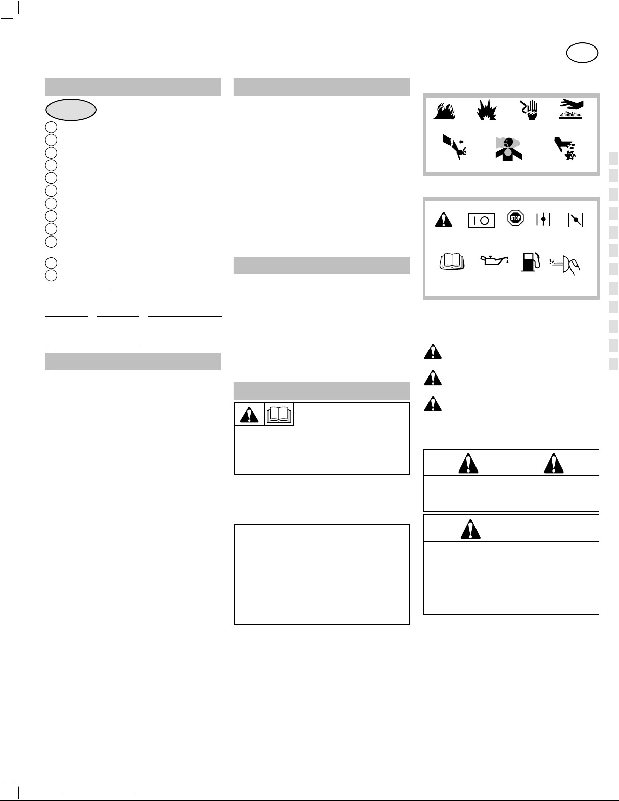
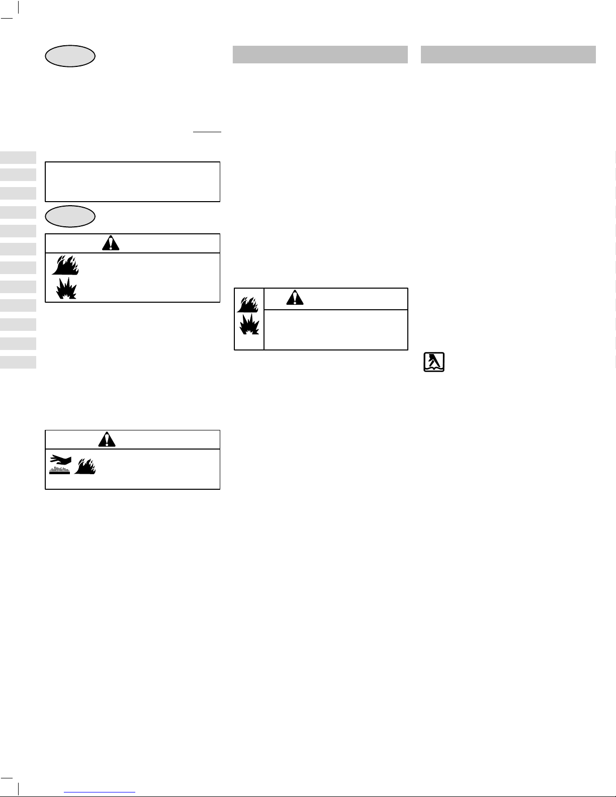
Hazard Symbols and Meanings
Fire
Kickback
Explosion
Toxic Fumes
Shock
Moving Parts
International Symbols and Meanings
Safety Alert
Read Operator’s
A signal word (DANGER, WARNING, or CAUTION) is used
with the alert symbol to indicate the likelihood and the potential
severity of injury. In addition, a hazard symbol may be used to
represent the type of hazard.
On Off
Manual
DANGER indicates a hazard which, if not avoided,
will result in death or serious injury.
WARNINGindicates a hazard which, if not avoided,
could result in death or serious injury.
CAUTION indicates a hazard which, if not avoided,
might result in minor or moderate injury.
CAUTION
indicates a situation that could result in damage to
the engine.
Oil
, when used without the alert symbol,
WARNING
The engine exhaust from this product contains chemicals known to the State of California to cause cancer,
birth defects, or other reproductive harm.
WARNING
Briggs & Stratton does not approve or authorize
the use of these engines on 3-wheel All Terrain
Vehicles (ATVs), motor bikes, aircraft products or
vehicles intended for use in competitive events.
Use of these engines in such applications could
result in property damage, serious injury (including
paralysis), or even death.
Stop
Fuel
Open
Choke
GB
Hot Surface
Full
Choke
Primer
bulb
1
Page 4
GBDDKE FGRI NNLPSSF
WARNING
Gasoline and its vapors are extremely
flammable and explosive.
Fire or explosion can cause severe
burns or death.
WHEN ADDING FUEL
• Turn engine OFF and let engine cool at least 2
minutes before removing gas cap.
• Fill fuel tank outdoors or in well-ventilated
area.
• Do not overfill fuel tank.
• Keep gasoline away from sparks, open
flames, pilot lights, heat, and other ignition
sources.
• Check fuel lines, tank, cap, and fittings
frequently for cracks or leaks. Replace if
necessary.
WHEN STARTING ENGINE
• Make sure spark plug, muffler,fuel cap and air
cleaner are in place.
• Do not crank engine with spark plug removed.
• If fuel spills, wait until it evaporates before
starting engine.
• If engine floods, set choke to OPEN/RUN
position, place throttle in FASTand crank until
engine starts.
WHEN OPERATING EQUIPMENT
• Do not choke carburetor to stop engine.
WHEN TRANSPORTING EQUIPMENT
• Transport with fuel tank EMPTY.
WHEN STORING GASOLINE OR EQUIPMENT WITH
FUEL IN TANK
• Store away from furnaces, stoves, water
heaters or other appliances that have pilot
light or other ignition source because they can
ignite gasoline vapors.
WARNING
Starting engine creates sparking.
Sparking can ignite nearby flammable
gases.
Explosion and fire could result.
• If there is natural or LP gas leakage in area,
do not start engine.
• Do not use pressurized starting fluids
because vapors are flammable.
WARNING
Rapid retraction of starter cord (kickback) will pull hand and arm toward
engine faster than you can let go.
Broken bones, fractures, bruises or
sprains could result.
• When starting engine, pull cord slowly until
resistance is felt, then pull rapidly.
• Direct coupled equipment components such
as, but not limited to, blades, impellors,
pulleys, sprockets, etc., must be securely
attached.
WARNING
Rotating parts can contact or entangle hands, feet, hair, clothing, or
accessories.
Traumatic amputation or severe
laceration can result.
• Operate equipment with guards in place.
• Keep hands and feet away from rotating parts.
• Tie up long hair and remove jewelry.
• Do not wear loose-fitting clothing, dangling
drawstrings or items that could become
caught.
WARNING
Running engines produce heat.
Engine parts, especially muffler,
become extremely hot.
Severe thermal burns can occur
on contact.
Combustible debris, such as
leaves, grass, brush, etc. can
catch fire.
• Allow muffler, engine cylinder and fins to cool
before touching.
• Remove accumulated combustibles from
muffler area and cylinder area.
• Install and maintain in working order a spark
arrester before using equipment on forestcovered, grass-covered, brush-covered
unimproved land. The state of California
requires this (Section 4442 of the California
Public Resources Code). Other states may
have similar laws. Federal laws apply on
federal land.
WARNING
Unintentional sparking can result
in fire or electric shock.
Unintentional start-up can result in
entanglement, traumatic amputation, or laceration.
BEFORE PERFORMING ADJUSTMENTS OR
REPAIRS
• Disconnect spark plug wire and keep it away
from spark plug.
WHEN TESTING FOR SPARK
• Use approved spark plug tester.
• Do not check for spark with spark plug
removed.
OIL RECOMMENDATIONS
CAUTION:
Engine shipped from Briggs & Stratton without oil. Before
starting engine
Use a high quality detergent oil classified “For Service SF, SG,
SH, SJ” or higher such as Briggs & Stratton 30, Part Number
100005. Use no special additives with recommended oils. Do
not mix oil with gasoline.
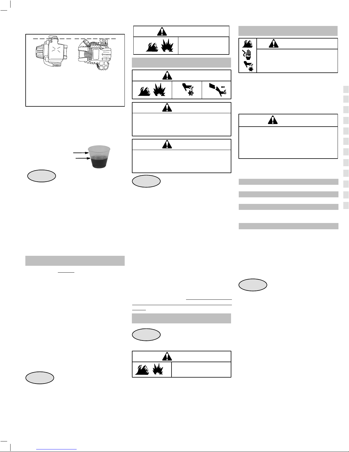
Fig. 2
, fill with oil. Do not over-fill.
Choose the SAE viscosity grade of oil
from this chart that matches the starting
temperature anticipated before the next
oil change.
CAUTION: Air cooled engines run hotter than
automotive engines. The use of non-synthetic
multi-viscosity oils (5W-30, 10W-30, etc.) in
temperatures above 40° F(4°C) will result in higher
than normal oil consumption. When using a
multi-viscosity oil, check oil level more frequently.
* CAUTION: Synthetic oil must be used
when operating engine under 40° F(4° C) or
engine damage will occur.
** CAUTION: SAE 30 oil, if used below 50° F
(10° C), will result in hard starting and possible
engine bore damage due to inadequate
lubrication.
Synthetic oil meeting ILSAC GF-2, API certification mark and API service symbol (shown
at left) with “SJ/CF ENERGY CONSERVING”
or higher, is an acceptable oil at all temperatures. Use of synthetic oil does not alter required
oil change intervals.
WARNING
Engines give off carbon monoxide, an odorless, colorless, poison gas.
Breathing carbon monoxide can
cause nausea, fainting or death.
• Start and run engine outdoors.
• Do not start or run engine in enclosed area,
even if doors or windows are open.
2
Page 5
GBDDKE FGRI NNLPSSF
Checking or Adding Oil
CAUTION:
To check oil, engine must be level,
with oil fill facing up. if not level, dipstick reading
will not be accurate and could lead to possible
over/under filling of oil. This may lead to possible
engine damage.
• Check oil level before starting the engine.
• Check oil level before every use.
• Keep oil level at FULL.
• DO NOT overfill, use oil measure cup for filling.
• Add only 30ml (1 oz)
a time.
➊_-- 15ml (0.5 oz) ➋ ofoil at
➊
➋
Fig. 3
1. Place engine level. Remove dipstick. Using oil
measure cup, pour oil slowly. Do not overfill.
2. Tocheck oil level, remove dipstick and wipe clean
with cloth. Replace dipstick and tighten down.
3. Remove and check oil level. Level should be at
FULL mark.
4. Verify FULL level of oil by the presence of oil in
hole on dipstick, or by measure line.
5. If oil is required, add 15ml (0.5oz) oil at a time.
Recheck level.
OIL PROCEDURE
➊.
Note: Engine holds approximately 90 ml.
➋
FUEL RECOMMENDATIONS
Use clean, fresh, lead-free gasoline with a minimum of
85 octane. Leaded gasoline may be used if it is
commercially available and if unleaded is unavailable.
Purchase fuel in quantity that can be used within 30
days. See Storage.
In U.S.A. leaded gasoline may not be used. Some
fuels, called oxygenated or reformulated gasolines, are
gasolines blended with alcohols or ethers. Excessive
amounts of these blends can damage the fuel system
or cause performance problems. If any undesirable
operating symptoms occur, use gasoline with a lower
percentage of alcohol or ether.
This engine is certified to operate on gasoline. Exhaust
Emission Control System: EM (Engine Modifications).
Do not use gasoline which contains Methanol. Do not
mix oil with gasoline.
For engine protection, we recommend using Briggs &
Stratton Fuel Stabilizer available from an Authorized
Briggs & Stratton Service Dealer.
Fig. 4
Tilt engine at angle shown to properly refuel. Clean
around fuel fill before removing cap. Fill tank to
approximately 1-1/2 inches below top of neck to allow
for fuel expansion. Be careful not to overfill.
ADDING FUEL
WARNING
Before refueling, allow
engine to cool 2 minutes.
STARTING
WARNING
CAUTION
Check oil level before starting engine. Oil level
should be at Full mark on dipstick before starting
engine. If started without oil, engine damage will
occur.
CAUTION
Operating engine at an excessive speed without
proper engine loading will cause damage. Do not
operate a string trimmer with a line shorter than 10”
(25 cm) diameter.
Fig. 5
1. Add oil and fuel as instructed in this manual.
2. Push
ENGINE, 8 times for all consecutive starts.
3. Red choke lever ➋ should be in the FULL
CHOKE
4. Squeeze throttle trigger
➎ sharply until engine runs.
5. Wait a maximum 10 seconds, then move choke
lever to HALF CHOKE
6. Run the engine at HALF CHOKE for 20 seconds
or until unit accelerates smoothly. Move choke to
OFF
require a longer warm-up period on HALF
CHOKE)
7. Wait a minimum of 20 seconds, then release
throttle trigger.
STARTING A WARM ENGINE
H Follow steps under Starting, with the exception of
squeezing throttle trigger. It is not necessary
squeeze and hold throttle trigger to restart a
engine.
STOPPING
Fig. 5
• Depress stop switch ➑ to stop engine.
STARTING THE ENGINE
➊ primer bulb 15 times FOR NEW
➌ position.
➍ and pull starter handle
➏ position.
➐ position. (Colder temperatures will
warm
WARNING
DO NOT close choke to
stop engine.
MAINTENANCE
WARNING
To prevent accidental starting, remove
spark plug wire and ground it before
servicing.
Regular maintenance improves performance and
extends engine life. More frequent service is required
when operating in adverse conditions.
See any Authorized Briggs & Stratton Service Dealer
for correct replacement parts. Other parts may not
perform as well, may damage the engine, result in
injury, or void your warranty.
WARNING
Do not strike the flywheel with hammer or hard
object. If done, the flywheel may shatter during
operation.
Do not tamper with links or other parts to increase
engine speed.
Follow the hourly or calendar intervals, whichever
occur first. More frequent service is required when
operating in adverse conditions noted below.
Before Every Use
D Check oil level
First 4 Hours
D Change oil
Every 8 Hours or Every Season
D Change oil
D Service air cleaner *
Every 50 Hours or Every Season
D Replace spark plug**
D Check valve clearance
* Clean more often under dusty conditions, or when
airborne debris is present or after prolonged operation
cutting tall, dry grass.
** In some areas, local law requires using a resistor spark
plug to suppress ignition signals. If this engine was
originally equipped with resistor spark plug, use same
type of spark plug for replacement.
Fig. 6
1. Change oil while the engine is warm, ensure fuel
to
cap is tightened securely.
2. Remove dipstick, and drain oil
shown.
3. Place engine level. Using oil measure cup pour oil
slowly adding 0.5 oz. at a time
4. Tocheck oil level, remove dipstick and wipe clean
with cloth. Replace dipstick and tighten down.
5. Remove and check oil level. Level should be at
FULL mark.
6. Verify FULL level of oil by the presence of oil in
hole on dipstick, or by measure line.
7. If oil is required, add 15ml (0.5oz) oil at a time.
Recheck level.
8. Replace dipstick tightly before starting engine.
CHANGING OIL
& CHECKING LEVEL
➊ in direction
➋. Do not overfill.
Note: Engine holds approximately 90 ml.
➌
3
Page 6
GBDDKE FGRI NNLPSSF
Fig. 7
AIR CLEANER MAINTENANCE
Replace Oil-Foam element if very dirty or damaged.
• Push cover tab
away from engine to service air filter.
➊ to release cover, then pull cover
• Check and clean the intake chamber for dirt.
• Wash Oil-Foam element ➋ in liquid detergent
and water. Squeeze dry in a clean cloth. Saturate
Oil-Foam element in engine oil and squeeze in a
clean cloth to remove excess oil.
• Engine will smoke if too much oil is left on filter.
CAUTION:
Do not use pressurized air or solvents to clean.
Pressurized air can damage filter; solvents will
dissolve filter.
Fig. 8
SPARK PLUG MAINTENANCE
WARNING
DO NOT check for spark with spark
plug removed. Use only Briggs & Stratton Spark Tester, to check for spark. DO
NOT crank engine with spark plug
removed.
• The electrodes on a spark plug must be clean and
sharp to produce the powerful spark required for
ignition. If the spark plug is worn or dirty the harder
it is to start your engine. Replace the spark plug
each season.
• Spark plug gap should be .64 mm or 0.025 in.
➋
KEEP ENGINE CLEAN
Periodically remove grass and chaff build-up from
engine. Clean finger guard.
Do not spray engine with water to clean because water
could contaminate fuel. Clean with a brush or
compressed air.
WARNING
Engine should be kept clean to
reduce risk of overheating and
ignition of accumulated debris.
Clean engine when engine is cold.
STORAGE
The following precautions should be taken if storing
your trimmer unit for a period exceeding 30 days, or for
seasonal storage.
• While engine is still warm, change oil.
• Clean engine of surface debris, chaff or grass.
• Drain all fuel from fuel tank into proper receptacle
for storage.
• Press the primer bulb 15 times to purge fuel from
carburetor and fuel lines. Drain remaining fuel into
proper receptacle. If fuel is to be disposed, please
refer to local rules for proper disposal.
• Remove spark plug. Place 1 teaspoon or 5 cc of oil
into spark plug hole.
• Pull starter rope slowly 8-10 times to properly coat
the cylinder bore and piston for storage. Replace
spark plug and tighten. Any residual oil may burn
off in subsequent starts. This may result in white
smoke emission from muffler.
• This trimmer may be stored in a variety of
positions. It is best to store in horizontal position
with the spark plug up. Do not store or transport
with the spark plug down.
Note: Storing or transporting with the spark plug down
will result in hard starting and/or engine smoking.
WARNING
Store in a clean, dry area. DO NOT store
near a stove, furnace or water heater
which uses a pilot light or any device that
can create a spark.
• When removing the unit from storage, only use
fresh gasoline. Perform operation checks, see
maintenance schedule, before starting engine.
SERVICE
See an Authorized Briggs & Stratton Service Dealer.
Each one carries a stock of Genuine Briggs &
Stratton Parts and is equipped with special service
tools. Trained mechanics assure expert repair
service on all Briggs & Stratton engines. Only
dealers advertising as “Authorized Briggs &
Stratton” are required to meet Briggs & Stratton
standards.
Partial List of Genuine Briggs & Stratton Parts
Oil 100005..............................
Synthetic Oil 100074......................
Oil pump kit (uses standard electric drill 5056.....
to remove oil from engine quickly)
Gas additive 5041.........................
Fuel hose assembly 696935.................
Air filter-foam 696923......................
Resistor spark plug 696876..................
Spark tester 19368........................
Spark plug wrench 89838 -or- 5023............
Repair manual 275072.....................
To purchase, or view other produc ts Briggs &
Stratton has available, see an Authorized Briggs &
Stratton Service Dealer. Use our web site at
www.briggsandstratton.com to find a dealer
nearest you, or check the “Yellow Pages”.
Walking fingers logo and “Yellow Pages” are registered
trademarks in various jurisdictions.
Need Assistance? Go to the website or call,
1-800-233-3723, (U.S.A. and Canada) to hear a
menu of pre-recorded messages offering engine
maintenance information.
4
Page 7
GBDDKE FGRI NNLPSSF
Briggs & Stratton Corporation (B&S),
the California Air Resources Board (CARB)
Environmental Protection Agency (U.S. EPA)
Emission Control System Warranty Statement
(Owner’s Defect Warranty Rights and Obligations)
and the United States
EMISSION CONTROL WARRANTY COVERAGE IS APPLICABLE TO CERTIFIED ENGINES PURCHASED IN
CALIFORNIA IN 1995 AND THEREAFTER, WHICH ARE
USED IN CALIFORNIA, AND TO CERTIFIED MODEL
YEAR 1997 AND LATER ENGINES WHICH ARE PURCHASED AND USED ELSEWHERE IN THE UNITED
STATES (AND AFTER JANUARY 1, 2001 IN CANADA).
California, United States and Canada Emission Con-
trol Defects Warranty Statement
The California Air Resources Board (CARB), U.S. EPA
and B&S arepleased to explain the Emission Control System Warranty on your model year 2000 and later small offroad engine (SORE). In California, new small off-road
engines must be designed, built and equipped to meet the
State’s stringent anti-smog standards. Elsewhere in the
UnitedStates, new non-road,spark-ignition engines certified for model year 1997 and later,must meet similar standards set forth by the U.S. EPA. B&S must warrant the
emission control system on your engine for the periods of
time listed below, provided there has been no abuse,
neglect or improper maintenance of your small off-road
engine.
Your emission control system includes parts such as the
carburetor, air cleaner, ignition system, muffler and catalytic converter. Also included may be connectors and other emission related assemblies.
Where a warrantablecondition exists, B&S will repair your
small off-road engine at no cost to you including diagnosis, parts and labor.
Briggs & Stratton Emission Control
Defects Warranty Coverage
Small off-road engines are warranted relative to emission
control parts defects for a period of two years, subject to
provisions set forth below. If any covered part on your engine is defective, the part will be repaired or replaced by
B&S.
Owner’s Warranty Responsibilities
As the small off-road engine owner, you are responsible
for the performance of the required maintenance listed in
your Operating and Maintenance Instructions. B&S recommends that you retain all your receipts covering maintenance on your small off-road engine, but B&S cannot
deny warranty solely for the lack of receipts or for your failure to ensure the performance of all scheduled maintenance.
As the small off-road engine owner, you should however
be aware that B&S may deny you warranty coverage if
your small off-road engine or a part has failed due to
abuse, neglect, improper maintenance or unapproved
modifications.
Youare responsible for presenting your small off-road engine to an Authorized B&S Service Dealer as soon as a
problem exists. The undisputed warranty repairs should
be completed in a reasonable amount of time, not to exceed 30 days.
If you have any questions regarding your warranty rights
and responsibilities, you should contact a B&S Service
Representative at 1-414-259-5262.
The emission warranty is a defects warranty. Defects are
judged on normal engine performance. The warranty is
not related to an in-use emission test.
Briggs & Stratton Emission Control
Defects Warranty Provisions
The following are specific provisions relativeto your Emission Control Defects Warranty Coverage. It is in addition
to the B&S engine warranty for non-regulated engines
found in the Operating and Maintenance Instructions.
1. Warranted Parts
Coverage under this warranty extends only to the parts
listed below (the emission control systems parts) to the
extent these parts were present on the engine purchased.
a. Fuel Metering System
• Cold start enrichment system (soft choke)
• Carburetor and internal parts
• Fuel Pump
b. Air Induction System
• Air cleaner
• Intake manifold
c. Ignition System
• Spark plug(s)
• Magneto ignition system
d. Catalyst System
• Catalytic converter
• Exhaust manifold
• Air injection system or pulse valve
e. Miscellaneous Items Used in Above Systems
• Vacuum, temperature, position, time sensitive
valves and switches
• Connectors and assemblies
2. Length of Coverage
B&S warrants to the initial owner and each subsequent
purchaser that the Warranted Parts shall be free from defects in materials and workmanship which caused the failure of the Warranted Parts for a period of two years from
the date the engine is delivered to a retail purchaser.
3. No Charge
Repair or replacement of any Warranted Part will be per-
formed at no charge to the owner, including diagnostic labor which leads to the determination that a Warranted
Part is defective, if the diagnostic work is performed at an
Authorized B&S Service Dealer. For emissions warranty
service contact your nearest Authorized B&S Service
Dealer as listed in the “Yellow Pages” under “Engines,
Gasoline,” “Gasoline Engines,” “Lawn Mowers,” or similar
category.
4. Claims and Coverage Exclusions
Warranty claims shall be filed in accordance with the pro-
visions of the B&S Engine WarrantyPolicy.Warranty coverage shall be excluded for f ailures of Warranted Parts
which are not original B&S parts or because of abuse, neglect or improper maintenance as set forth in the B&S Engine Warranty Policy. B&S is not liable to cover failures of
Warranted Parts caused by the use of add-on, non-original, or modified parts.
5. Maintenance
Any Warranted Part which is not scheduled for replace-
ment as required maintenance or which is scheduled only
for regular inspection to the effect of “repair or replace as
necessary” shall be warranted as to defects for the war ranty period. Any Warranted Part which is scheduled for
replacement as required maintenance shall be warranted
as to defects only for the period of time up to the first
scheduled replacement for that part. Any replacement
part that is equivalent in performance and durability may
be used in the performance of any maintenance or repairs. The owner is responsible for the performance of all
required maintenance, as defined in the B&S Operating
and Maintenance Instructions.
6. Consequential Coverage
Coverage hereunder shall extend to the failure of any en-
gine components caused by the failure of any Warranted
Part still under warranty.
Look For Relevant Emission
Durability Period and
Air Index Information On
Your Engine Emission Label
Engines that are certified to meet the California Air
Resources Board (CARB) Tier 2 Emission Standards
must display information regarding the Emissions Durability Period and the Air Index. Briggs & Stratton makes
this information available to the consumer on our emission labels. The engine label will indicate certification
information.
The Emission Durability Period describes the number
of hours of actual running time for which the engine is
certified to be emission compliant, assuming proper
maintenance in accordance with the Operating & Maintenance Instructions. The following categories are used:
Moderate: Engine is certified to be emission
compliant for 125 hours of actual engine running time.
Intermediate: Engine is certified to be emission
compliant for 250 hours of actual engine running time.
Extended: Engine is certified to be emission
compliant for 500 hours of actual engine running time.
Forexample, a typical walk-behind lawn mower is used 20
to 25 hours per year. Therefore, the Emission Durability
Period of an engine with an intermediate rating would
equate to 10 to 12 years.
The Air Index is a calculated number describing the
relative level of emission for a specific engine family. The
lower the Air Index, the cleaner the engine. This
information is displayed in graphical form on the emission
label.
In the state of California, the 120000 series engines
covered in this manual are certified by the California Air
Resources Board to meet emissions standards for 125
hours. Such certification does not grant the purchaser,
owner or operator of this engine any additional warranties
with respect to the performance or operational life of this
engine. This engine is warranted solely according to the
productand emissions warrantiesstatedelsewhere in this
manual.
After July 1, 2000, Look For Emissions
Compliance Period On Engine Emissions
Compliance Label
After July 1, 2000 certain Briggs & Stratton engines will be
certified to meet the United States Environmental Protection Agency (USEPA) Phase 2 emission standards. For
Phase 2 certified engines, the Emissions Compliance
Period referred to on the Emissions Compliance label
indicates the number of operating hours for which the
engine has been shown to meet Federal emission
requirements.Forengines less than 225 cc displacement,
Category C = 125 hours, B = 250 hours and A = 500 hours.
For engines of 225 cc or more, Category C = 250 hours, B
= 500 hours and A = 1000 hours.
The displacement of Model Series 21000 engines is 34cc.
The displacement of Model Series 21100 engines is 40cc.
This is a generic representation of the emission label typically found
on a certified engine.
5
Page 8

GBDDKE FGRI NNLPSSF
BRIGGS & STRATTON ENGINE OWNER WARRANTY POLICY
Effective January 1, 2003 replaces all undated Warranties and all Warranties dated before January 1, 2003
Briggs & Stratton Corporation will repair or replace, free of charge, any part(s) of the engine that is defective in material or workmanship or both. Transportation charges on parts submitted for repair or replacement under this warranty must be borne by purchaser.This warranty is effective for the time
periods and subject to the conditions stated below. For warranty service, find the nearest Authorized Service Dealer in our dealer locator map at
www.briggsandstratton.com, or by calling 1-800-233-3723, or as listed in the ‘Yellow Pages’.
THERE IS NO OTHER EXPRESS WARRANTY. IMPLIED WARRANTIES, INCLUDING THOSE OF MERCHANTABILITY AND FITNESS FOR A PARTICULAR PURPOSE, ARE LIMITED TO ONE YEAR FROM PURCHASE, OR TO THE EXTENT PERMITTED BY LAW ANY AND ALL IMPLIED WARRANTIES ARE EXCLUDED. LIABILITY FOR INCIDENTAL OR CONSEQUENTIAL DAMAGES ARE EXCLUDED TO THE EXTENT EXCLUSION IS
PERMITTED BY LAW. Some states or countries do not allow limitations on how long an implied warranty lasts, and some states or countries do not
allowthe exclusion or limitation of incidental or consequential damages, so the above limitation and exclusion may not apply to you. This warranty gives
you specific legal rights and you may also have other rights which vary from state to state and country to country.
OUR PRODUCT
LIMITED WARRANTY
VANGUARD
ELS
I/Cr
Industrial Plus
Intek
(Sleeve Bore)
Fource
Intek
(Kool Bore)
Power Built OHV
QUANTUMr
Quattro
Q45
Sprint
Classic
Etek
WARRANTY PERIOD*
Consumer Use
2 years
2 years
Commercial Use
* Note the following special warranty periods: 2 years for Classic engines in the European Union and Eastern European countries, for all consumer products in the European Union, and
for emission control systems on engines certified by EPA and CARB. 5 years for consumer use, 90 days for commercial use of Touch-N-Mowstarter on Quantum and Intek engines.
Engines used in competitive racing or on commercial or rental tracks are not warrantied.
The warranty period begins on the date of purchase by the first retail consumer or commercial end user, and continues for the period of time stated in the table above. “Consumer use”
means personal residential household use by a retail consumer. “Commercial use” means all other uses, including use for commercial, income producing or rental purposes. Once an
engine has experienced commercial use, it shall thereafter be considered as a commercial use engine for purposes of this warranty.
NO WARRANTY REGISTRATION IS NECESSARY TO OBTAIN WARRANTY ON BRIGGS & STRATTON PRODUCTS. SAVE YOUR PROOF OF PURCHASE RECEIPT.IF
YOU DO NOT PROVIDE PROOF OF THE INITIAL PURCHASE DATE AT THE TIME WARRANTY SERVICE IS REQUESTED, THE MANUFACTURING DATE OF THE
PRODUCT WILL BE USED TO DETERMINE THE WARRANTY PERIOD.
2 years
90 days1 year
1 year
90 days
1 year
ABOUT YOUR ENGINE WARRANTY
Briggs & Stratton welcomes warranty repair and apologizes to
you for being inconvenienced. Any Authorized Service Dealer
may perform warranty repairs. Most warranty repairs are handled routinely, but sometimes requests for warranty service
may not be appropriate. For example, warranty would not apply
if engine damage occurred because of misuse, lack of routine
maintenance, shipping, handling, warehousing or improper
installation. Similarly, warranty is void if the serial number of the
engine has been removed or the engine has been altered or
modified.
If a customer differs with the decision of the Service Dealer, an
investigation will be made to determine whether the warranty
applies. Ask the Service Dealer to submit all supporting facts to
his Distributor or the Factory for review. If the Distributor or the
Factory decides that the claim is justified, the customer will be
fully reimbursed for those items that are defective. To avoid misunderstanding which might occur between the customer and
the Dealer, listed below are some of the causes of engine failure
that the warranty does not cover.
Normal wear:
Engines, like all mechanical devices, need periodic parts service and replacement to perform well. Warranty will not cover
repair when normal use has exhausted the life of a part or an
engine.
Improper maintenance:
Thelife of anengine depends upon the conditions under which it
operates, and the care it receives. Some applications, such as
tillers, pumps and rotary mowers, are very often used in dusty or
dirty conditions, which can cause what appears to be premature
wear.Such wear,when caused by dirt, dust, spark plug cleaning
Briggs & Stratton Engines Are Made Under One Or More Of The Following Patents: Design D-247,177 (Other Patents Pending)
6,325,036
6,284,123
6,260,529
6,230,678
6,202,616
6,116,212
6,077,063
6,064,027
6,014,808
5,894,715
5,852,951
5,823,153
5,819,513
5,813,384
5,765,713
5,645,025
5,642,701
5,619,845
5,606,948
5,606,851
5,548,955
5,546,901
5,503,125
5,501,203
grit, or other abrasive material that has entered the engine because of improper maintenance, is not covered by warranty.
Thiswarranty covers engine related defective materialand/
or workmanship only, and not replacement or refund of the
equipment to which the engine may be mounted. Nor does
the warranty extend to repairs required because of:
1. PROBLEMS CAUSED BY PARTS THAT ARE NOT
ORIGINAL BRIGGS & STRATTON PARTS.
2. Equipment controls or installations that prevent starting,
cause unsatisfactory engine performance, or shorten engine life. (Contact equipment manufacturer.)
3. Leaking carburetors, clogged fuel pipes, sticking valves,
or other damage, caused by using contaminated or stale
fuel. (Use clean, fresh, lead-free gasoline and Briggs &
Stratton Fuel Stabilizer, Part No. 5041.)
4. Parts which are scored or broken because an engine was
operated with insufficient or contaminated lubricating oil,
or an incorrect grade of lubricating oil (check oil level daily
or after every 8 hours of operation. Refill when necessary
and change at recommended intervals.) OIL GARD
may not shut down running engine. Engine damage may
occur if oil level is not properly maintained. Read Operating & Maintenance Instructions.
5. Repair or adjustment of associated parts or assemblies
such as clutches, transmissions, remote controls, etc.,
which are not manufactured by Briggs & Stratton.
6. Damage or wear to parts caused by dirt, which entered
the engine because of improper air cleaner maintenance,
re-assembly, or use of a non-original air cleaner element
or cartridge. (At recommended intervals, clean and re-oil
5,497,679
5,320,795
5,271,363
5,269,713
5,265,700
5,243,878
5,235,943
5,197,425
5,197,422
5,191,864
5,188,069
5,186,142
5,138,996
5,086,890
5,070,829
5,058,544
5,040,644
5,009,208
the Oil-Foam element or the foam pre-cleaner, and
replace the cartridge.) Read Operating & Maintenance
Instructions.
7. Parts damaged by over-speeding, or overheating caused
by grass, debris, or dirt, which plugs or clogs the cooling
fins, or flywheel area, or damage caused by operating the
engine in a confined area without sufficient ventilation.
(Clean fins on the cylinder, cylinder head and flywheel at
recommendedintervals.) Read Operating &Maintenance
Instructions.
8. Engine or equipment parts broken by excessive vibration
caused by a loose engine mounting, loose cutter blades,
unbalanced blades or loose or unbalanced impellers, improper attachment of equipment to engine crankshaft,
over-speeding or other abuse in operation.
9. A bent or broken crankshaft, caused by striking a solid object with the cutter blade of a rotary lawn mower, or excessive v-belt tightness.
10. Routine tune-up or adjustment of the engine.
11. Engine or engine component failure, i.e., combustion
chamber, valves, valve seats, valve guides, or burned
starter motor windings, caused by the use of alternate
fuels such as, liquified petroleum, natural gas, altered
gasolines, etc.
Warranty is available only through service dealers which
have been authorized by Briggs & Stratton Corporation.
your nearest Authorized Service Dealer is listed in the “Yellow Pages” of your telephone directory under “Engines,
Gasoline” or “Gasoline Engines,” “Lawn Mowers,” or similar category.
4,996,956
4,977,879
4,971,219
4,895,119
4,819,593
4,719,682
4,633,556
4,630,498
4,522,080
4,520,288
4,512,499
4,453,507
4,430,984 DES. 308,871
DES. 308,872
DES. 309,457
DES. 356,951
DES. 361,771
DES. 375,963
6
Page 9

E
COMPONENTES DEL MOTOR
VEA LA FIG.
1
Carburador
2
Suiche de Parada
3
Manija de la Cuerda
4
Llenado de combustible
5
Filtro de Aire
6
Estrangulador
7
Bujía con resistencia
8
Manguera de Retorno de Combustible
9
Manguera de Admisión de Combustible
10
Aceite
11
Motor Modelo / Tipo / Número de Código
XXXXXX XXXX−XX
Registre los números del Modelo, Tipo y Código de
su motor aquí para un futuro uso.
Registre aquí su fecha de compra para un futuro uso.
1
INFORMACIÓN TÉCNICA
Clasificación de Potencia
La clasificación de potencia para un modelo de motor en
particular se desarrolla inicialmente comenzando con el
código J1940 de SAE (Sociedad de Ingenieros Automotrices)
(Procedimiento de Clasificación de Potencia & Torque del
Motor Pequeño) (Revisión 2002−05). Dado ambos un amplio
conjunto de productos en los cuales son puestos nuestros
motores, y la variedad de asuntos ambientales aplicables al
operar el equipo, puede que el motor que usted haya
comprado no desarrolle la potencia nominal cuando sea
usado en una parte del equipo acoplado (potencia real
en−el sitio"). Esta diferencia es debido a una variedad de
factores incluyendo, pero no limitándose a, lo siguiente:
diferencias en altitud, temperatura, presión barométrica,
humedad, combustible, lubricación del motor, máxima
velocidad regulada del motor, el motor particular a la
variabilidad del motor, diseño de la parte en particular del
equipo acoplado, la manera en la cual es operado el motor, el
despegue −del motor para reducir la fricción y la limpieza de las
cámaras de combustión, los ajustes a las válvulas y al
carburador, y otra variedad de factores. Esta clasificación de
potencia puede también ser ajustada basándose en
comparaciones a otros motores semejantes utilizados en
aplicaciones similares, y por lo tanto no se igualarán
necesariamente los valores derivados usando los códigos
anteriores.
ESPECIFICACIONES DE AJUSTE
Entrehierro de la bujía 0.76 mm (0.25 pulg.). . . . . .
Entrehierro del inducido 0.25 − 0.36 mm. . . . . . . .
(0.010 − 0.014 pulg.). . . . . . . . . . . . . . . . . . . . . . .
Tolerancia de la válvula de admisión 0.05 − 0.10 mm
(0.002 − 0.004 pulgadas). . . . . . . . . . . . . . . . . . . .
Tolerancia de la válvula de escape 0.05 − 0.10 mm.
(0.002 − 0.004 pulgadas). . . . . . . . . . . . . . . . . . . .
Nota: La potencia del motor disminuirá 3−1/2% por cada
1,000 pies (300 metros) sobre el nivel del mar y un 1% por
cada 10° F (5.6° C) por encima de 77° F (25° C).
En los Estados Unidos de América, los motores series 21000 y
21100 que se cubren en este manual están certificados por la
Junta de Recursos Ambientales de California por cumplir las
normas de emisiones durante 50 horas. Tal certificación no
reconoce al comprador, propietario u operador de este motor
ninguna garantía adicional con respecto al desempeño o vida
operacional de este motor. Este motor está garantizado
únicamente conforme a las garantías del producto y de
emisiones declaradas en otra parte en este manual.
ESPECIFICACIONES DE SEGURIDAD
ANTES DE OPERAR EL MOTOR
• Lea completamente las Instrucciones
de Mantenimiento & Operación Y las
instrucciones para el equipo acoplado a este
motor.*
• Dejar de seguir las instrucciones podría
ocasionar lesiones graves o incluso la muerte.
LAS INSTRUCCIONES DE MANTENIMIENTO &
OPERACIÓN CONTIENEN INFORMACION DE
SEGURIDAD PARA
• Hacer que usted tome conciencia de los
peligros asociados con los motores
• Informarlo a usted del riesgo de las heridas
asociado con aquellos peligros, y
• Contarle como evitar o reducir el riesgo de
una herida.
* Briggs & Stratton no conoce necesariamente el equipo que
va a acoplar este motor. Por esta razón, usted debe leer
cuidadosamente y comprender las instrucciones de
operación para el equipo en el cual es colocado su motor.
SÍMBOLOS DE PELIGRO
SÍMBOLOS INTERNACIONALES
Aviso de
Seguridad
Lea el Manual
del Operario
identificar información de seguridad concerniente a los
peligros que pueden producir lesiones personales.
Una palabra señalizada (PELIGRO, ADVERTENCIA o
PRECAUCION) es usada con el símbolo de aviso para indicar
la probabilidad de una herida y su gravedad potencial.
Además, un símbolo de peligro puede ser utilizado para
representar el tipo de peligro.
On Off
Aceite
El símbolo de aviso de seguridad es usado para
PELIGRO indica un peligro que si no es evitado,
ocasionará la muerte o heridas graves.
ADVERTENCIA indica un peligro que si no es
evitado, ocasionaría la muerte o heridas graves.
PRECAUCION indica un peligro que si no es
evitado, podría ocasionar heridas menores o
moderadas.
PRECAUCION, cuando es usado sin el símbolo de
aviso, indica una situación que podría ocasionar
daños en el motor.
Parada
Estrangu−
lador
Abierto
Combustible
E
Estran−
gulación
Tot a l
Bulbo
cebador
Modelos Serie: 21000
Diámetro Interno 40 mm (1.575 pulg.). . . . . . . . . . .
Carrera 27 mm (1.065 pulg.). . . . . . . . . . . . . . . . . .
Desplazamiento 34 CC (2.074 pulgadas cúbicas). .
Modelo Serie 21100
Diámetro Interno 40 mm (1.575 pulg.). . . . . . . . . . .
Carrera 32 mm (1.250 pulg.). . . . . . . . . . . . . . . . . .
Desplazamiento 40 CC (2.44 pulgadas cúbicas). . .
Fuego
Partes en
Movimiento
Explosión
Gases Tóxicos
Contra−
golpe
19
Superficie
Caliente
Descarga Eléctrica
Page 10

E
ADVERTENCIA
La gasolina y sus vapores son
extremadamente inflamables y
explosivos.
El fuego o una explosión pueden causar
graves quemaduras o la muerte.
CUANDO AÑADA COMBUSTIBLE
• Gire el motor hacia la posición OFF y deje que
el motor se enfríe por lo menos 2 minutos
antes de remover la tapa de gasolina.
• Llene el tanque de combustible en exteriores
o en un área bien ventilada.
• No llene demasiado el tanque de
combustible. Llene el tanque
aproximadamente 40 mm (1−1/2 pulgadas)
por debajo de la parte superior del cuello para
permitir la expansión del combustible.
• Mantenga la gasolina a distancia de chispas,
llamas abiertas, luces piloto, calor y otras
fuentes de encendido.
• Compruebe con frecuencia si existen grietas
o fugas en los conductos de combustible, el
tanque, la tapa y en los accesorios.
Cámbielos si es necesario.
CUANDO DE ARRANQUE AL MOTOR
• Asegúrese que la bujía, el mofle, la tapa de
combustible y el filtro de aire estén en su
lugar.
• No haga girar el motor si removió la bujía.
• Si se derramó combustible, espere hasta que
se haya evaporado antes de dar arranque al
motor.
• Si el motor se inunda, ajuste el estrangulador
a la posición OPEN/RUN, coloque el
acelerador en la posición FAST y haga girar el
motor hasta que arranque.
CUANDO OPERE EL EQUIPO
• No incline el motor ni el equipo a un ángulo
que pueda ocasionar derrames de gasolina.
• No ahogue el carburador para detener el
motor.
CUANDO TRANSPORTE EL EQUIPO
• Transpórtelo con el tanque de combustible
VACIO o con la válvula de cierre de
combustible en la posición OFF.
CUANDO ALMACENE GASOLINA O EL EQUIPO
CON COMBUSTIBLE EN EL TANQUE
• Almacene a distancia de hornos, estufas,
calentadores de agua u otros aparatos que
utilicen luz piloto u otras fuentes de
encendido ya que estos pueden encender los
vapores de gasolina.
ADVERTENCIA
Dar arranque al motor crea chispeo.
El chispeo puede encender los gases
inflamables cercanos.
Podría presentarse fuego o una
explosión.
• Si hay una fuga de gas natural o LP en el
área, no de arranque al motor.
• No use líquidos de arranque presurizado ya
que los vapores son inflamables.
ADVERTENCIA
Los motores emiten monóxido de
carbono, un gas venenoso que
carece de olor y de color.
Respirar monóxido de carbono
puede ocasionar náuseas,
desmayos o la muerte.
• De arranque al motor y opérelo en exteriores.
• No de arranque al motor ni lo opere en un
área encerrada, aun cuando las puertas o las
ventanas se encuentren abiertas.
ADVERTENCIA
El gas de escape del motor que produce este
producto contiene químicos conocidos para el
Estado de California que ocasionan cáncer,
defectos de nacimiento, u otros daños
reproductivos.
ADVERTENCIA
Briggs & Stratton no aprueba ni autoriza el uso de
estos motores en Vehículos Todo Terreno de
3−ruedas (ATVs), bicicletas motorizadas,
productos para la aviación o en vehículos que
tengan como fin ser usados en eventos
competitivos. El uso de estos motores en tales
aplicaciones podría ocasionar daños a la
propiedad, lesiones graves (incluyendo parálisis),
o incluso la muerte.
ADVERTENCIA
La retracción rápida de la cuerda de
arranque (contragolpe) le halará la
mano y el brazo hacia el motor más
rápido de lo que usted la pueda
dejar ir.
Podrían ocasionarse roturas de
huesos, fracturas, moretones o
torceduras.
• Cuando de arranque al motor, hale
lentamente la cuerda hasta que se sienta
resistencia, después hale la cuerda
rápidamente.
• Remueva todas las cargas externas del
equipo/motor antes de dar arranque al motor.
• Los componentes de acople directo del
equipo tal como, pero no limitados a,
cuchillas, impulsores, poleas, dientes de
piñones, etc. se deben asegurar firmemente.
ADVERTENCIA
El funcionamiento de los motores
produce calor. Las partes de los
motores, especialmente el mofle,
se calientan demasiado.
Pueden ocurrir graves quemaduras
a causa de su contacto.
Desechos combustibles, tal como
hojas, grama maleza, etc. pueden
alcanzar a encenderse.
• Deje que el mofle, el cilindro y las aletas del
motor se enfríen antes de tocarlos.
• Remueva los combustibles acumulados en el
área del mofle y en el área del cilindro.
• Instale y mantenga en orden de
funcionamiento un atrapachispas antes de
utilizar el equipo en una zona con vegetación
tupida o en terrenos agrestes con grama. El
Estado de California lo exige (Sección 4442
del Código de Recursos Públicos de
California). Otros estados pueden tener leyes
similares. Las leyes federales se aplican en
tierras federales.
ADVERTENCIA
Un chispeo involuntario puede
producir fuego o una descarga
eléctrica.
Una puesta en marcha involuntaria
puede ocasionar un enredo, una
amputación traumática o una
laceración.
ANTES DE HACER AJUSTES O REPARACIONES
• Desconecte el cable de la bujía y manténgalo
a distancia de bujía.
• Desconecte la batería en la terminal negativa
(únicamente motores con arranque
eléctrico).
CUANDO COMPRUEBE CHISPA
• Utilice un probador de bujías aprobado.
• NO compruebe chispa si removió la bujía.
RECOMENDACIONES DE COMBUSTIBLE
Use gasolina corriente sin plomo, con un mínimo de
87 octanos, que esté limpia y fresca.
Puede usarse gasolina con plomo si ésta es
comercialmente disponible y si no se dispone de
gasolina sin plomo.
Compre una provisión de combustible que pueda
usarse en un período de 30 días. El combustible fresco
evita que se formen depósitos de goma en el sistema
de combustible.
Este motor está certificado para operar con gasolina.
Sistema de Control de Emisiones de Escape: EM
(Modificaciones del Motor).
ADVERTENCIA
APAGUE EL MOTOR Y DEJE QUE SE
ENFRIE POR LO MENOS DURANTE
2 MINUTOS ANTES DE REMOVER EL
TAPON DE COMBUSTIBLE PARA
REAPROVISIONAR.
No use gasolina que contenga Metanol. No mezcle
aceite con gasolina.
20
Page 11

E
VEA LA FIG.
5
Incline el motor al ángulo mostrado para llenar
apropiadamente el tanque de combustible.
Llene el tanque hasta aproximadamente
1−1/2 pulgadas por debajo de la parte superior del
cuello para permitir la expansión del combustible. No lo
llene demasiado el tanque. Coloque nuevamente el
tapón de combustible antes de arrancar.
RECOMENDACIONES DE ACEITE
PRECAUCIÓN
El motor es despachado de Briggs & Stratton sin
aceite. Antes de dar arranque al motor,
aprovisiónelo de aceite. No lo llene demasiado.
CAPACIDAD DE ACEITE: 90 ml (3 onzas)
Use un aceite detergente de alta calidad clasificado
Para Servicio SH, SJ" o superior. No use aditivos
especiales con aceites recomendados. Elija un grado
de viscosidad de aceite del cuadro.
VEA LA FIG.
PRECAUCION: El aceite de viscosidad
SAE 30, si es usado por debajo de 50° F
(10° C), producirá dificultad de arranque y
un posible daño en el bloque del motor
debido a una lubricación inadecuada.
* PRECAUCION: El aceite sintético debe
ser usado cuando se opere el motor bajo
una temperatura de 40
contrario ocurrirá un daño en el motor.
** PRECAUCION: El uso de aceites
multígrados no sintéticos (5W−30, 10W−30,
etc.) a temperaturas superiores a 40° F
(4° C) producirá más alto consumo de
aceite del normal.
El aceite sintético que cumple con ILSAC GF−2,
marca de certificación API y símbolo de servicio
API (mostrado a la izquierda) con CONSERVA−
CION DE ENERGIA SJ/CF" o superior, es un
aceite aceptable para todas las temperaturas. El
uso de aceites sintéticos no altera los intervalos
de cambio de aceite requeridos.
COMPROBACIÓN O APROVISIONAMIENTO DE
ACEITE
PRECAUCION: VEA LA FIG.
Para comprobar el aceite, el motor debe estar a
nivel, con el tubo de llenado de aceite hacia arriba. Si
no se encuentra a nivel, la lectura de la varilla
indicadora de nivel no será exacta y podría conducir a
un llenado de aceite excesivo o insuficiente. Esto
puede ocasionar un posible daño en el motor.
VEA LA FIG.
• Remueva la varilla indicadora de nivel de aceite
para añadir aceite
• Después de remover la varilla indicadora de nivel
de aceite, límpiela con un trapo limpio, insértela y
apriétela nuevamente.
• Remueva la varilla indicadora de nivel y
compruebe el nivel de aceite. El aceite debe
alcanzar la marca FULL
• Si se requiere aceite, añádalo lentamente
la taza de Medición de Aceite. Añada únicamente
de 1 onza
2
° F (4° C) o de lo
3
4
.
en la varilla.
. Use
a 0.5 onzas de aceite a la vez.
ARRANQUE
VEA LA FIG.
Compruebe el nivel de aceite antes de darle
arranque al motor. El aceite debe alcanzar la marca
Full en la varilla indicadora de nivel antes de darle
arranque al motor. Si el motor es arrancado sin
aceite, ocurrirá un daño en el motor.
Operar un motor a una velocidad excesiva sin la
carga adecuada en el motor ocasionará daños. No
opere una guadañadora de nylon con una cuerda
más corta de 10" (25 cm) de diámetro.
ARRANQUE DEL MOTOR
• Compruebe el nivel de aceite.
• Añada combustible y re−instale la tapa de
combustible.
• Coloque la unidad sobre una superficie plana.
• Oprima el
MOTOR NUEVO, 8 veces para todos los
arranques consecutivos.
• La palanca del estrangulador
posición de estrangulación total
• Apriete el gatillo del acelerador
de arranque
el motor.
• Espere 10 segundos, después mueva la palanca
del estrangulador hacia posición de MEDIO
ESTRANGULADOR
• Espere un mínimo de 20 segundos, después
mueva el estrangulador hacia la posición OFF
• Suelte el gatillo del acelerador.
ARRANQUE DE UN MOTOR CALIENTE
6
ADVERTENCIA
PRECAUCIÓN
PRECAUCIÓN
bulbo cebador 15 veces PARA UN
debe estar en la
.
y hale la manija
rigurosamente hasta que funcione
.
H Siga los pasos establecidos bajo el aparte:
Arranque, sin presionar el gatillo del acelerador. No es
necesario presionar y sostener el gatillo del acelerador
para volver a dar arranque a un motor caliente.
PARADA
VEA LA FIG.
• Oprima el suiche de parada para detener el motor.
6
ADVERTENCIA
NO cierre el estrangulador
para detener el motor.
MANTENIMIENTO
ADVERTENCIA
Para prevenir un arranque accidental,
remueva el cable de la bujía y
conéctelo a tierra antes de darle
servicio.
VEA LAS FIGURAS
7 8 9
10 11
El mantenimiento regular mejora el funcionamiento y
alarga la vida del motor. Se requiere un servicio más
frecuente cuando se opere en condiciones adversas.
Busque un Distribuidor de Servicio Autorizado
Briggs & Stratton para conseguir los repuestos
correctos. Otras partes pueden no funcionar bien y
podrían dañar el motor, ocasionar lesiones o invalidad
su garantía.
ADVERTENCIA
No golpee la volante con un martillo ni con un objeto
pesado, Si lo hace, la volante puede cizallarse
durante la operación.
NO manipule las varillas u otras partes para
incrementar la velocidad del motor.
Siga los intervalos por horas de trabajo o por
calendario, lo que ocurra primero. Se puede requerir
un servicio más frecuente cuando se opera bajo
condiciones adversas como las anotadas a
continuación.
Antes de Cada Uso
D Compruebe el nivel de aceite
Las Primeras 4 horas
D Cambie aceite
Cada 8 horas o cada estación
D Cambie aceite
D De servicio al filtro de aire *
Cada 50 horas o cada estación
D Cambie el filtro de combustible
D Cambie la bujía**
Cada estación
D Compruebe la tolerancia de la válvula
* Limpie con mayor frecuencia bajo condiciones de mucho
polvo, o cuando se presenten muchos desechos en el
aire o después de una operación prolongada cortando
grama alta y seca.
** En algunas áreas las leyes locales requieren el uso de
una bujía con resistencia para suprimir las señales de
encendido. Si este motor vino originalmente equipado
con una bujía con resistencia, utilice el mismo tipo de
bujía cuando la vaya a cambiar.
MANTENIMIENTO PARA EL ACEITE
VEA LA FIG.
Cambie el aceite mientras que el motor esté caliente,
asegúrese que el tapón de combustible esté
firmemente asegurado.
Remueva la varilla indicadora de nivel de aceite, y
drene el aceite en la dirección mostrada.
Coloque el motor a nivel. Remueva la varilla indicadora
de nivel de aceite. Con una taza de medición de aceite
vierta aceite lentamente añadiendo 0.5 onzas a la
. NO LO LLENE DEMASIADO.
vez
Vea el procedimiento de llenado de aceite bajo el
aparte: Recomendaciones para el Aceite.
7
21
Page 12

E
MANTENIMIENTO PARA EL FILTRO DE
AIRE
VEA LA FIG.
Cambie el elemento de Espuma−Aceitada si está
muy sucio o dañado.
• Presione la aleta de la tapa
aparte después la tapa del motor para darle
servicio al filtro de aire.
• Revise y limpie la cámara de admisión por si tiene
suciedades.
• Lave el elemento de Espuma−Aceitada
detergente líquido y agua. Escurra hasta secarlo
con un trapo limpio. Sature el elemento de
Espuma−Aceitada en aceite para motor y
escúrralo en un trapo limpio para remover el
exceso de aceite.
• El motor echará humo si se deja mucho aceite en
el filtro.
PRECAUCIÓN
No use aire a presión ni solventes para limpiar el
filtro. El aire a presión puede dañar el filtro; los
solventes deshacen el filtro.
8
para liberar la tapa,
en
MANTENIMIENTO DE LA BUJÍA
VEA LA FIG.
• Los electrodos en una bujía deben estar limpios y
agudos para producir la chispa de gran alcance
requerida para el encendido. Si la bujía está
desgastada o sucia más difícil será arrancar el su
motor. Cambie la bujía cada estación.
• El entrehierro de la bujía debe ser de .64 mm o
0.025 pulgadas.
9
ADVERTENCIA
NO compruebe chispa si removió la
bujía. Use únicamente el Probador de
Chispa Briggs & Stratton, para compro−
bar chispa. No de arranque al motor si
removió la bujía.
FILTRO DE COMBUSTIBLE
INCORPORADO AL TANQUE
VEA LA FIG.
Drene el tanque de combustible antes de
cambiar el filtro de combustible. El
combustible puede escaparse, creando
Los repuestos para el sistema de combustible
(tapones, mangueras, tanques, filtros, etc.)
deben ser iguales a las partes originales, de lo
contrario puede ocurrir un incendio.
PRECAUCIÓN
El filtro
admisión de combustible
filtro a la manguera adecuada se ocasionarán
daños en su motor.
un peligro de incendio/explosión.
debe estar asegurado a la manguera de
10
ADVERTENCIA
. Si no se asegura el
MANTENGA LIMPIO EL MOTOR
Remueva periódicamente los cortes de grama y los
desechos acumulados en el motor. Limpie el protector
de dedos.
No rocíe el motor con agua para limpiar el motor ya que
el agua podría contaminar el combustible. Límpielo
con un cepillo o con aire comprimido.
ADVERTENCIA
El motor debe mantenerse limpio
para reducir el riesgo de
enciendan los desechos que estén acumulados.
Limpie el motor cuando esté frío.
recalentamiento y evitar que se
AJUSTES
AJUSTES DEL CARBURADOR
VEA LA FIG.
11
ADVERTENCIA
El fabricante del equipo en el cual es instalado el
motor especifica la velocidad máxima en la cual
será operado el motor. NO EXCEDA esta
velocidad.
El carburador en este motor es de bajas emisiones. El
tornillo de velocidad de ralentí viene ajustado de
fábrica.
PARA AJUSTAR EL CARBURADOR Y AJUSTAR LA
VELOCIDAD DE RALENTI
• Prenda el motor y caliéntelo aproximadamente
durante 5 minutos antes de hacer ajustes.
• Con el motor funcionando, libere el control del
acelerador.
• Para comprobar la velocidad de ralentí use un
tacómetro (B&S P/N 19389).
• Mueva la palanca del acelerador
tornillo de velocidad de ralentí
• Gire el tornillo en sentido de las agujas del reloj
para incrementar la velocidad, en sentido
contrario al de las agujas del reloj para disminuir la
velocidad. Ajuste el tornillo de velocidad de ralentí
hasta obtener 4000 rpm mínimo.
• Libere la palanca del acelerador. Presione el
control del acelerador para acelerar el motor. El
motor debe acelerar suavemente.
contra el
, y sosténgalo.
BODEGAJE
Los motores almacenados durante más de 30 días
necesitan atención especial.
Para prevenir que se forme goma en el sistema del
combustible o en las partes esenciales del carburador:
a) si el tanque de combustible contiene gasolina
oxigenada o reformulada (gasolina mezclada con un
alcohol o con éter), opere el motor hasta que éste se
detenga por la falta de combustible, o b) si el tanque de
combustible contiene gasolina, opere también el motor
hasta que éste se detenga por la falta de combustible,
o añada un estabilizador de gasolina a la gasolina en el
tanque.
Nota: Si se usa un estabilizador, opere el motor durante
varios minutos para que el aditivo circule por el
carburador. Después se puede almacenar el motor y el
combustible.
1. Cambie aceite
2. Remueva la bujía y vierta aproximadamente
15 ml (1/2 onza) de aceite para motor en el
interior del cilindro. Coloque de nuevo la bujía y
haga girar el motor lentamente para distribuir el
aceite.
3. Limpie los desechos del motor.
4. Almacene en un área limpia y seca.
Se recomienda el uso del Estabilizador de Combustible
Briggs & Stratton disponible a través de cualquier
Distribuidor de Servicio Autorizado Briggs & Stratton.
ADVERTENCIA
No almacene cerca de una estufa, horno
o calentador de agua los cuales utilicen
testigo piloto ni cerca de cualquier
dispositivo que pueda crear chispa.
SERVICIO
Busque un Centro de Servicio Autorizado
Briggs & Stratton. Cada centro mantiene un stock
de Partes Originales Briggs & Stratton y está
equipado con herramientas de servicio especiales.
Los mecánicos entrenados le garantizan un experto
servicio de reparación en todos los motores
Briggs & Stratton. Sólo los centros que se anuncien
como Autorizados por Briggs & Stratton" satisfacen
los estándares requeridos por Briggs & Stratton.
Lista Parcial de Partes Originales
Aceite 100005. . . . . . . . . . . . . . . . . . . . . . . . . . . .
Aceite Sintético 100074. . . . . . . . . . . . . . . . . . . . .
Kit bomba de aceite 5056. . . . . . . . . . . . . . . . . . .
(usa un taladro eléctrico estándar para remover
rápidamente el aceite del motor)
Aditivo para gasolina 5041. . . . . . . . . . . . . . . . . .
Filtro de combustible 696918. . . . . . . . . . . . . . . . .
Conjunto manguera de combustible 696935. . . . . . .
Espuma−filtro de aire 696923. . . . . . . . . . . . . . . . .
Bujía con resistencia 696876. . . . . . . . . . . . . . . . .
Probador de chispa 19368. . . . . . . . . . . . . . . . . .
Llave de bujía 89838 −o− 5023. . . . . . . . . . . . . . . .
Manual de Reparación 275072. . . . . . . . . . . . . . . .
Para comprar, o visualizar otros productos
que Briggs & Stratton tenga disponibles,
consulte un Distribuidor de Servicio Autorizado
Briggs & Stratton. Utilice nuestro sitio web en
Briggs & Stratton
www.briggsandstratton.com para encontrar
el distribuidor más cercano a usted, o busque en las
Páginas Amarillas".
El logo de los dedos caminando y las Páginas
Amarillas" son marcas registradas en varias
jurisdicciones.
Necesita Asistencia? Visite nuestro sitio web o
marque el 1−800−233−3723, (Estados Unidos y
Canadá) para escuchar un menú de mensajes
pre−grabados que le ofrecen información
relacionada con el mantenimiento del motor.
22
Page 13

E
Briggs & Stratton Corporation (B&S), Junta de
Recursos Ambientales de California (CARB) y Agencia
de Protección Ambiental de los Estados Unidos (U.S.
EPA) / Declaración de la Garantía del Sistema de
Control de Emisiones (Derechos y Obligaciones del
Propietario de la Garantía de Defectos)
LA COBERTURA DE LA GARANTIA DEL CONTROL DE
EMISIONES ES APLICABLE A LOS MOTORES
CERTIFICADOS QUE HAYAN SIDO COMPRADOS EN
CALIFORNIA A PARTIR DE 1995 Y DESPUÉS DE ESTA
FECHA, LOS CUALES SEAN USADOS EN CALIFORNIA, Y
PARA LOS MOTORES CERTIFICADOS MODELOS 1997 EN
ADELANTE QUE SEAN COMPRADOS Y USADOS EN OTRA
PARTE DE LOS ESTADOS UNIDOS (Y A PARTIR DE ENERO
1 DE 2001 EN CANADA).
Declaración de la Garantía de Defectos del Sistema de
Control de Emisiones de California, Estados Unidos y
La Junta de Recursos Ambientales (CARB), La Agencia de
Protección Ambiental de los Estados Unidos U.S. EPA y B&S
se complacen en explicarles la Garantía del Sistema de
Control de Emisiones de su motor pequeño modelo 2000 y
posteriores para uso en terrenos sin pavimento (SORE). En
California, los nuevos motores pequeños para uso en
terrenos sin pavimento deben ser diseñados, fabricados y
equipados para cumplir los rigurosos estándares anti−smog
del Estado. En cualquier otra parte de los Estados Unidos, los
nuevos motores de encendido por chispa para no uso en
carreteras modelos 1997 y posteriores, deben cumplir
estándares similares a los establecidos por la Agencia de
Protección Ambiental de los Estados Unidos (U.S. EPA). B&S
debe garantizar el sistema de control de emisiones en su
motor por los períodos de tiempo listados abajo, teniendo en
cuenta que no haya habido abuso, negligencia o
mantenimiento no apropiado en su motor pequeño para uso
en terrenos sin pavimento.
Su sistema de control de emisiones incluye partes tales como
el carburador, el filtro de aire, el sistema de encendido, el
mofle y el convertidor catalítico. También puede incluir
conectores y otros conjuntos relacionados con el sistema de
emisiones.
Siempre que exista una condición de garantía, B&S reparará
su motor pequeño para uso en terrenos sin pavimento sin
ningún costo para usted incluyendo el diagnóstico, las partes
y la mano de obra.
Cobertura de la Garantía de Defectos del Sistema de
Control de Emisiones Briggs & Stratton
Los motores pequeños para uso en terrenos sin pavimento se
garantizan relativo a los defectos de las partes del sistema de
control de emisiones durante un período de dos años, sujeto a
las provisiones establecidas abajo. Si alguna de las partes
bajo cobertura en su motor se encuentra defectuosa, la parte
será reparada o reemplazada por B&S.
Responsabilidades del Propietario de la Garantía
Como propietario de un motor pequeño para uso en terrenos
sin pavimento, usted es responsable de que se lleve a cabo el
mantenimiento requerido el cual se indica en sus
Instrucciones de Mantenimiento y Operación. B&S le
recomienda guardar todos sus recibos que cubran el
mantenimiento en su motor pequeño para uso en terrenos sin
pavimento, pero B&S no solo puede negar la garantía por la
falta de recibos sino por su omisión al asegurar la realización
de todo el mantenimiento programado.
No obstante, como propietario de un motor pequeño para uso
en terrenos sin pavimento, usted tiene que darse cuenta que
B&S puede negarle la cobertura de la garantía si su motor
pequeño para uso en terrenos sin pavimento o una de sus
partes ha fallado debido a abuso, negligencia, mantenimiento
incorrecto o modificaciones no aprobadas
Usted es responsable de presentar su motor pequeño para
uso en terrenos sin pavimento a un Distribuidor de Servicio
Autorizado B&S tan pronto se presente el problema. Las
reparaciones bajo garantía indisputables deben completarse
en un período de tiempo razonable que no se exceda de
30 días.
Si usted tiene algunas preguntas relacionadas con los
derechos y responsabilidades de la garantía, debe contactar
a un Representante de Servicio B&S marcando el teléfono:
1−414−259−5262.
La garantía de emisiones es una garantía de defectos. Los
defectos son juzgados en el desempeño normal de un motor.
La garantía no está relacionada con una prueba de emisiones
en uso.
Canadá
Provisiones de la Garantía de Defectos del Sistema
de Control de Emisiones Briggs & Stratton
Las siguientes son provisiones específicas relativas a la
Cobertura de Garantía de Defectos del Sistema de Control de
Emisiones. Es una adición a la garantía del motor B&S para
los motores no−regulados encontrados en las Instrucciones
de Mantenimiento y Operación.
1. Partes Garantizadas
La cobertura bajo esta garantía se extiende únicamente a
las partes listadas abajo (partes de los sistemas de
control de emisiones) a la extensión que estas partes
estaban presentes en el motor comprado.
a. Sistema de Medición de Combustible
• Sistema de Enriquecimiento de Arranque en Frío
(estrangulación suave)
• Carburador y Partes Internas
• Bomba de Combustible
b. Sistema de Inducción de Aire
• Filtro de Aire
• Múltiple de Admisión
c. Sistema de Encendido
• Bujía(s)
• Sistema de Encendido con Magneto
d. Sistema Catalizador
• Convertidor Catalítico
• Múltiple de Escape
• Sistema de Inyección de Aire o Válvula de
Pulsación
e. Items Varios Usados en los Sistemas Anteriores
• Vacío, Temperatura, Posición, Válvulas
Sensitivas de Tiempo y Suiches
• Conectores y Conjuntos
2. Duración de la Cobertura
B&S garantiza al propietario inicial y a cada comprador
subsecuente que las Partes Garantizadas estarán libres
de defectos en materiales y mano de obra la cual haya
ocasionado fallas de las Partes Garantizadas por un
período de dos años a partir de la fecha en que es
entregado el motor a un comprador detallista.
3. Sin Costo
La reparación o cambio de cualquier Parte Garantizada
se llevará a cabo sin costo alguno para el propietario,
incluyendo la labor de diagnóstico la cual conduce a la
determinación de que esa Parte Garantizada es
defectuosa, si el trabajo de diagnóstico es realizado en un
Centro de Servicio Autorizado B&S. Para servicio de
garantía de emisiones contacte su Centro de Servicio
Autorizado B&S más cercano listado en las Páginas
Amarillas" bajo Motores, Gasolina", Motores a
Gasolina", Máquinas Cortacésped" o en una categoría
similar.
4. Reclamos y Exclusiones de la Cobertura
Los reclamos de la garantía se completarán de acuerdo
con las provisiones de la Póliza de Garantía del Motor
B&S. La cobertura de la garantía estará excluida para
fallas de las Partes Garantizadas las cuales no sean
partes originales B&S o por abuso, negligencia o
mantenimiento incorrecto según se establece en la Póliza
de Garantía del Motor B&S. B&S no se hace responsable
de cubrir fallas de Partes Garantizadas ocasionadas por
el uso de adición de partes, partes no−originales o partes
modificadas.
5. Mantenimiento
Cualquier parte garantizada la cual no esté programada
para cambio al realizar el mantenimiento requerido o la
cual esté programada únicamente para una inspección
regular por el efecto de repare o cambie si es necesario"
se garantizará por defectos durante el período de la
garantía. Cualquier Parte Garantizada la cual esté
programada para cambio por el mantenimiento requerido
se garantizará únicamente por defectos durante el
período de tiempo hasta el primer cambio programado
para esa parte. Cualquier repuesto que sea equivalente
en desempeño y durabilidad puede ser usado al llevar a
cabo toda tarea de mantenimiento o reparación. El
propietario es responsable de la realización de todo el
mantenimiento requerido, según se define en las
Instrucciones de Mantenimiento y Operación B&S.
6. Cobertura Consecuente
La cobertura aquí establecida se extenderá hasta la falla
de cualquiera de los componentes del motor ocasionada
por la falla de cualquier Parte Garantizada que aún se
encuentre bajo garantía.
Busque el Período de Durabilidad
de Emisiones y la Información del
Índice de Aire Pertinentes en su
Etiqueta de Emisiones del Motor
Los motores que son certificados para cumplir con las
Normas de Emisiones Etapa 2 de la Junta de Recursos
Ambientales de California (CARB) deben mostrar la
información referente al Período de Durabilidad de Emisiones
y al Índice de Aire. Briggs & Stratton hace que esta
información esté disponible para el consumidor en nuestras
etiquetas de emisiones. La etiqueta del motor indicará la
información de certificación.
El Período de Durabilidad de Emisiones describe el
número de horas del tiempo real de operación para el cuál
está certificado el motor por cumplir con las emisiones,
asumiendo un mantenimiento apropiado de acuerdo con las
Instrucciones de Mantenimiento y Operación. Se utilizan las
siguientes categorías:
Moderado: El motor es certificado para cumplir con
las emisiones durante 125 horas del tiempo real de operación
del motor.
Intermedio: El motor es certificado para cumplir con
las emisiones durante 250 horas del tiempo real de operación
del motor.
Prolongado: El motor es certificado para cumplir con
las emisiones durante 500 horas del tiempo real de operación
del motor.
Por ejemplo, una máquina cortacésped de arrastrar típica es
usada de 20 a 25 horas por año. Por lo tanto, el Período de
Durabilidad de Emisiones de un motor con una clasificación
intermedia se igualaría de 10 a 12 años.
El Índice de Aire es un número calculado que describe el
nivel relativo de emisiones para una familia específica de
motores. Mientras más bajo sea el Índice de Aire, más limpio
será el motor. Esta información es mostrada en forma gráfica
en la etiqueta de emisiones.
En el estado de California, los motores serie 120000 cubiertos
en este manual están certificados por la Junta de Recursos
Ambientales de California por cumplir las normas de
emisiones durante 125 horas. Tal certificación no reconoce al
comprador, propietario u operador de este motor ninguna
garantía adicional con respecto al desempeño o vida
operacional de este motor. Este motor está garantizado
únicamente conforme a las garantías del producto y de
emisiones declaradas en otra parte en este manual.
Después de Julio 1, 2000, Busque el
Período de Conformidad de Emisiones en
la Etiqueta de Conformidad de Emisiones
del Motor.
Después de Julio 1, 2000 ciertos motores Briggs & Stratton
estarán certificados por cumplir con las normas de emisiones
Fase 2 de la Agencia de Protección Ambiental de los Estados
Unidos (USEPA). Para los motores certificados Fase 2, el
Período de Conformidad de Emisiones al cual se refiere la
Etiqueta de Conformidad de Emisiones indica el número de
horas de operación para las cuales el motor ha demostrado
que cumple con los requerimientos Federales de emisiones.
Para motores con un desplazamiento inferior a 225 cc,
Categoría C = 125 horas, B = 250 horas y A = 500 horas. Para
motores con un desplazamiento de 225 cc o superior,
Categoría C = 250 horas, B = 500 horas y A = 1000 horas.
El desplazamiento de los motores Modelo Serie 21000 es
34cc.
El desplazamiento de los motores Modelo Serie 21100 es
40cc.
Esta es una
representación genérica
de una etiqueta de
emisiones típicamente
encontrada en un motor
certificado.
23
Page 14

E
POLIZA DE GARANTIA DEL PROPIETARIO DEL MOTOR BRIGGS & STRATTON
Vigente a partir de Enero 1, 2003 reemplaza todas las Garantías previas sin fecha y todas las Garantías fechadas antes de Enero 1, 2003
Briggs & Stratton Corporation reparará o reemplazará, sin costo alguno, cualquier parte(s) del motor consideradas como defectuosas en material, mano de obra o
ambos. Los gastos de transporte de las partes sometidas a reparación o cambio bajo esta Garantía deben ser abonados por el comprador. Esta garantía tiene vigencia
durante el período de tiempo señalado en la misma, quedando sujeta a las condiciones establecidas en esta póliza. Para recibir servicio de garantía, contacte su Centro
de Servicio Autorizado más cercano en nuestro mapa de localización de distribuidores en www.briggsandstratton.com, o marque el 1-800-233-3723, o según aparezca
listado en las ‘Páginas Amarillas’.
NO EXISTE NINGUNA OTRA GARANTIA EXPRESA. LAS GARANTIAS IMPLICITAS, INCLUSO AQUELLAS DE MERCANTIBILIDAD O ADAPTABILIDAD PARA UN
FIN DETERMINADO QUEDAN LIMITADAS A UN AÑO A PARTIR DE LA FECHA DE COMPRA O A LA EXTENSIÓN PERMITIDA POR LA LEY, QUEDANDO EXCLUIDAS
TODAS LAS GARANTIAS IMPLICITAS. LA RESPONSABILIDAD POR DAÑOS FORTUITOS O CONSECUENTES BAJO CUALQUIER Y TODAS LAS GARANTIAS
QUEDA EXCLUIDA EN LA MEDIDA QUE DICHA EXCLUSION SEA PERMITIDA POR LA LEY. Algunos países o estados no contemplan limitaciones en cuanto a la
duración de una garantía implícita, y otros países o estados no permiten la exclusión o limitación de daños consecuentes o incidentales, en cuyo caso la limitación y la
exclusión anteriores pueden no ser aplicables para usted. Esta garantía le da derechos legales específicos, pudiendo tener a su vez otros derechos que varían de un país
a otro y de un estado a otro.
GARANTIA LIMITADA
NUESTRO PRODUCTO
VANGUARD
ELS
I/Cr
Industrial Plus
Intek
(Diámetro Camisa)
Fource
Intek
Cilindros de Aluminio
(Kool Bore)
Power Built OHV
QUANTUMr
Quattro
Q45
Sprint
Classic
Etek
PERIODO DE GARANTIA*
Uso Privado
2 años
Uso Comercial
* Observe los siguientes períodos especiales de garantía: 2 años para los motores Classic en los países de la Unión Europea y de Europa Oriental, para todos los productos del
consumidor en la Unión Europea, y para los sistemas del control de emisiones certificados por EPA y CARB. 5 años para uso privado, 90 días para uso comercial del sistema de arranque
El período de garantía comienza a partir de la fecha en la cual lo compró el consumidor detallista original o usuario final comercial, y continúa por el período de tiempo establecido en la
tabla anterior. “Uso privado” significa uso doméstico personal por el consumidor detallista original. “Uso Comercial” significa todos los otros usos, incluyendo fines comerciales o que
produzcan ingresos o renta. Una vez que el motor haya experimentado uso comercial, será considerado en adelante como motor de uso comercial para fines de esta garantía.
NO ES NECESARIA NINGUNA TARJETA DE REGISTRO (GARANTIA) PARA OBTENER LA GARANTIA EN PRODUCTOS BRIGGS & STRATTON. GUARDE SU RECIBO
CON LA PRUEBA DE LA FECHA DE COMPRA. SI USTED NO SUMINISTRA UNA PRUEBA DE LA FECHA DE COMPRA INICIAL EN EL MOMENTO DE REQUERIR
SERVICIO DE GARANTIA, SE USARA LA FECHA DE FABRICACION DEL PRODUCTO PARA DETERMINAR EL PERIODO DE GARANTIA.
Touch-N-Mow en los motores Quantum e Intek. Los motores usados en carreras competitivas o en trayectorias comerciales o de renta no están cubiertos por la garantía.
2 años 2 años
1 año
90 días
1 año
90 días
1 año
ACERCA DE LA GARANTIA DE SU MOTOR
Briggs & Stratton recibe con agrado la reparación bajo garantía y se
disculpa por los inconvenientes presentados. Cualquier Centro de
Servicio Autorizado puede hacer reparaciones bajo garantía. La
mayor parte de las reparaciones bajo garantía se atienden de
manera rutinaria, pero algunas veces las peticiones para el servicio
de garantía pueden no ser apropiadas. Por ejemplo, la garantía no
podría aplicarse si el daño del motor ocurrió debido a abuso, falta del
mantenimiento habitual, transporte, manejo, bodegaje o instalación
inapropiados. De igual manera se invalidará la garantía si el número
serial del motor ha sido removido o si el motor ha sido alterado o
modificado.
Si un cliente no está de acuerdo con la decisión del Centro de
Servicio, se realizará una investigación para determinar la
aplicabilidad de la garantía. Pida a su Centro de Servicio que envíe
toda la información pertinente a su Distribuidor o a la Fábrica para
proceder a su revisión. Si el Distribuidor o la Fábrica deciden que su
reclamación es justificada, al cliente le será reembolsado totalmente
el importe de aquellas partes que son defectuosas. Para evitar
cualquier malentendido que pudiera presentarse entre el cliente y el
Centro de Servicio, listamos a continuación algunas de las causas
de fallas del motor que no cubre la garantía.
Desgaste Normal:
Los motores, como todos los dispositivos mecánicos, necesitan el
cambio y el servicio periódico de las partes para desempeñarse
bien. La garantía no cubrirá la reparación cuando el uso normal haya
agotado la vida de una parte o de un motor.
Mantenimiento Incorrecto:
La vida útil de un motor depende de las condiciones bajo las cuales
opere el motor y del cuidado que éste reciba. Algunas aplicaciones,
tales como cultivadoras, bombas y máquinas cortacésped rotantes,
se utilizan con mucha frecuencia en condiciones de mucho polvo o
en condiciones muy sucias, las cuales pueden hacer que parezca un
desgaste prematuro del motor. Tal desgaste, cuando es ocasionado
por suciedad, polvo o por el hecho de limpiar la bujía con chorro de
Los Motores Briggs & Stratton Son Fabricados Bajo Una O Más De Las Siguientes Patentes: Diseño D−247.177 (Otras Patentes Pendientes)
6,325,036
6,284,123
6,260,529
6,230,678
6,202,616
6,116,212
6,077,063
6,064,027
6,014,808
5,894,715
5,852,951
5,823,153
5,819,513
5,813,384
5,765,713
5,645,025
5,642,701
5,619,845
5,606,948
5,606,851
5,548,955
5,546,901
5,503,125
5,501,203
arena, o porque otro material abrasivo haya entrado al motor debido
a un mantenimiento no apropiado, no será cubierto por la garantía.
Esta garantía cubre únicamente
de obra relacionados con el motor, y no el cambio o reembolso
del equipo en el cual haya sido montado el motor. Ni extenderá
la garantía a reparaciones requeridas debido a:
1. PROBLEMAS OCASIONADOS POR EL USO DE
PARTES QUE NO SEAN PARTES ORIGINALES
BRIGGS & STRATTON.
2. Controles del equipo o instalaciones que impidan el arranque,
ocasionando un rendimiento poco satisfactorio del motor, o
que acorten la vida del motor. (Contacte el fabricante del
equipo.)
3. Carburadores con fugas, conductos de combustible
obstruidos, válvulas atascadas u otros daños causados por el
uso de combustible contaminado o pasado. (Use gasolina
limpia, fresca y sin plomo y el Estabilizador para Combustible
de Briggs & Stratton Parte No. 5041.)
4. Partes que se hayan rayado o reventado por operar el motor
con aceite lubricante insuficiente o contaminado, o por el uso
del grado de viscosidad de aceite incorrecto (compruebe el
nivel de aceite diariamente o después de cada 8 horas de
operación. Rellene si es necesario y cámbielo según los
intervalos recomendados.) El dispositivo protector del aceite
OIL GARD" no se puede apagar durante la operación del
motor. Se podrían presentar daños en el motor si el nivel de
aceite no se mantiene correctamente. Lea las Instrucciones
de Mantenimiento & Operación.
5. Reparación o ajuste de partes asociadas o conjuntos tales
como embragues, transmisiones, controles remoto, etc., los
cuales no son fabricados por Briggs & Stratton.
6. Daño o desgaste de partes causado por la entrada de
suciedades al motor debido al mantenimiento incorrecto del
filtro de aire, montaje incorrecto, o por el uso de un elemento o
5,497,679
5,320,795
5,271,363
5,269,713
5,265,700
5,243,878
, material defectuoso y/o mano
5,235,943
5,197,425
5,197,422
5,191,864
5,188,069
5,186,142
5,138,996
5,086,890
5,070,829
5,058,544
5,040,644
5,009,208
cartucho para el filtro de aire que no sea original. (Limpie y
aceite nuevamente el elemento de Espuma Aceitada
pre−filtro de espuma y cambie el cartucho según los intervalos
recomendados.) Lea las Instrucciones de Mantenimiento &
Operación.
7. Partes dañadas por sobrevelocidad o recalentamiento
causado por residuos de grama, desechos o suciedades los
cuales taponan u obstruyen las aletas de enfriamiento, o el
área de la volante, o por daños causados por operar el motor
en un área confinada sin la suficiente ventilación. (Limpie las
aletas en el cilindro, la culata y la volante según los intervalos
recomendados.) Lea las Instrucciones de Mantenimiento &
Operación.
8. Partes del motor o del equipo quebradas por vibración
excesiva causada por un montaje flojo del motor, cuchillas de
corte flojas, cuchillas o impulsores flojos o no balanceados,
fijación incorrecta del equipo al cigüeñal del motor,
sobrevelocidad u otro abuso en la operación.
9. Un cigüeñal deformado o quebrado causado por golpear con
un objeto sólido la cuchilla de corte de una máquina
cortacésped rotante, o por tensión excesiva de las correas en
v.
10. Afinación o ajuste de rutina del motor.
11. Descuido del motor o de los componentes del motor, es decir,
cámara de combustión, válvulas, asientos de válvulas, guías
de válvulas o bobinados del motor de arranque quemados,
causado por el uso de combustibles alternos tales como,
petróleo líquido, gas natural, gasolinas alteradas, etc.
Usted dispone de la garantía únicamente a través de centros de
servicio que hayan sido autorizados por Briggs & Stratton
Corporation. Su Centro de Servicio Autorizado más cercano
aparece listado en las Páginas Amarillas" de su directorio
telefónico bajo Motores, Gasolina" o Motores a Gasolina",
Máquinas Cortacésped," o en una categoría similar.
4,996,956
4,977,879
4,971,219
4,895,119
4,819,593
4,719,682
4,633,556
4,630,498
4,522,080
4,520,288
4,512,499
4,453,507
4,430,984 DES. 308,871
o el
DES. 308,872
DES. 309,457
DES. 356,951
DES. 361,771
DES. 375,963
24
Page 15

F
COMPOSANTS DU MOTEUR
VOIR FIG.
1
Carburateur
2
Contacteur d’arrêt
3
Poignée de lanceur
4
Remplissage de carburant
5
Filtre à air
6
Starter
7
Bougie à résistance
8
Tuyau de retour du carburant
9
Tuyau d’arrivée du carburant
10
Huile
11
Modèle / Type / Code
XXXXXX XXXX−XX
Inscrire ici le Modèle , le Type et le Code de votre
moteur pour référence ultérieure.
Inscrire la date d’achat pour référence ultérieure.
1
INFORMATIONS TECHNIQUES
Puissance théorique
L’étalonnage de puissance d’un moteur est calculé au départ
selon le code J1940 (Procédure de calcul de la puissance et du
couple des petits moteurs) (Révision 2002−05) de la SAE
(Society of Automotive Engineers). Compte tenu de la grande
variété des machines où nos moteurs sont utilisés et du
nombre de problèmes environnementaux applicables au
fonctionnement des équipements, il se peut que le moteur que
vous avez acheté ne développe pas la puissance théorique
une fois qu’il est monté dans une machine particulière
(puissance réelle « sur site »). Cette différence s’explique par
un grand nombre de facteurs tels que les suivants (liste non
limitative) : différences d’altitude, de température, de pression
atmosphérique, d’humidité, de carburant, de lubrification du
moteur, de régime maximum autorisé par le régulateur,
variation d’un moteur à l’autre, conception de la machine sur
laquelle il est monté, rodage pour réduire les frottements et
propreté des chambres de combustion, réglages des
soupapes et du carburateur et de nombreux autres facteurs.
La puissance théorique peut aussi être ajustée par
comparaison avec d’autres moteurs similaires utilisés dans
des applications semblables ce qui fait qu’elle ne correspond
pas forcément à la valeur calculée précisément à l’aide du
code précité.
SPECIFICATIONS DE REGLAGE
Écartement des électrodes de bougie 0,76 mm. . .
Entrefer volant−bobine 0,25 à 0,36 mm. . . . . . . . .
(0,010 − 0,014 pouces). . . . . . . . . . . . . . . . . . . . .
Jeu des soupapes d’admission 0,05 à 0,10 mm. . .
(0,002 − 0,004 pouces). . . . . . . . . . . . . . . . . . . . .
Jeu des soupapes d’échappement 0,05 à 0,10 mm.
(0,002 − 0,004 pouces). . . . . . . . . . . . . . . . . . . . .
Remarque :
1 000 pieds (300 mètres) d’altitude au−dessus du niveau de la
mer et de 1 % par 10° F (5,6° C) au−dessus de 77° F (25° C).
Aux Etats−Unis, les moteurs de la série 21000 et 21100
couverts par ce manuel ont reçu du California Air Resources
Board la certification de conformité aux normes antipollution
pour 50 heures de fonctionnement. Cette certification
n’accorde aucune garantie supplémentaire de
fonctionnement ou de durée de vie pour ce moteur à son
acheteur, propriétaire ou utilisateur. La garantie de ce moteur
ne couvre que le produit et ses émissions certifiées indiquées
par ailleurs dans ce manuel.
La puissance du moteur décroît de 3,5 % par
SPECIFICATIONS DE SECURITE
AVANT DE DEMARRER LE
MOTEUR
• Lire entièrement les instructions d’utilisation et
d’entretien ET les instructions de l’équipement
entraîné par ce moteur.*
• Un non−respect de ces instructions peut
entraîner des blessures graves ou même
mortelles.
LES INSTRUCTIONS D’UTILISATION ET
D’ENTRETIEN CONTIENNENT DES
INFORMATIONS DE SECURITE POUR
• Que vous preniez bien connaissance des
risques liés à l’utilisation de moteurs
• Vous informer sur les blessures pouvant être
causées par ces risques, et
• Vous dire comment éviter ou réduire au
maximum les risques de blessures.
* Briggs & Stratton n’est pas nécessairement au courant de
l’application pour laquelle ce moteur est utilisé. Dès lors,
nous vous recommandons de lire attentivement le mode
d’emploi de l’équipement entraîné par ce moteur.
SYMBOLES DE DANGER
SYMBOLES INTERNATIONAUX
Alerte
sécurité
Lire le manuel
de l’opérateur
les informations de sécurité relatives aux risques pouvant
entraîner des blessures corporelles.
Un mot indicatif (DANGER, AVERTISSEMENT ou
ATTENTION) est utilisé avec le symbole d’alerte pour signaler
la possibilité et la gravité potentielle d’une blessure. De plus,
un symbole de danger peut être utilisé pour indiquer le type de
risque encouru.
Marche
Arrêt
Huile
Le symbole d’alerte de sécurité est utilisé pour signaler
DANGER indique un risque qui, s’il n’est pas
éliminé, entraînera la mort ou des blessures très
graves.
AVERTISSEMENT indique un risque qui, s’il n’est
pas éliminé, pourrait entraîner la mort ou des
blessures très graves.
ATTENTION indique un risque qui, s’il n’est pas
éliminé, pourrait entraîner des blessures
mineures ou légères.
ATTENTION, lorsqu’il est utilisé sans le symbole
d’alerte, indique une situation qui pourrait
endommager le moteur.
Arrêt
Carburant
Starter
fermé
F
Starter
à fond
Poire
d’amorçage
Modèle 21000
Alésage 40 mm. . . . . . . . . . . . . . . . . . . . . . . . . .
Course 27 mm. . . . . . . . . . . . . . . . . . . . . . . . . . .
Cylindrée 34 cm3. . . . . . . . . . . . . . . . . . . . . . . . .
Modèle 21100
Alésage 40 mm. . . . . . . . . . . . . . . . . . . . . . . . . .
Course 32 mm. . . . . . . . . . . . . . . . . . . . . . . . . . .
Cylindrée 40 cm3. . . . . . . . . . . . . . . . . . . . . . . . .
Incendie
Pièces en mouvement
Explosion
Fumées
toxiques
Retour brutal
25
Surface très
chaude
Choc
Page 16

F
ATTENTION
L’essence et les vapeurs d’essence
sont extrêmement inflammables et
explosives.
Un incendie ou une explosion peut
entraîner des blessures très graves
ou même la mort.
POUR FAIRE LE PLEIN
• Couper le moteur et le laisser refroidir au
moins 2 minutes avant d’ouvrir le bouchon du
réservoir.
• Remplir le réservoir de carburant à l’extérieur
ou dans un local extrêmement bien ventilé.
• Ne pas trop remplir le réservoir. Laisser
environ 4 cm sous le haut du col pour
permettre la dilatation du carburant.
• Tenir l’essence à l’écart des étincelles, des
flammes directes, des veilleuses, de la
chaleur et des autres sources d’étincelles.
• Contrôler que les Durits, le réservoir, le
bouchon et les raccords de carburant ne
présentent ni fissures ni fuites. Remplacer si
nécessaire.
POUR DEMARRER LE MOTEUR
• S’assurer que la bougie, le silencieux, le
bouchon du réservoir et le filtre à air sont bien
en place.
• Ne pas lancer le moteur quand la bougie est
retirée.
• Si du carburant a été renversé, attendre son
évaporation complète avant de démarrer le
moteur.
• Si le moteur est noyé, placer le starter sur
OPEN / RUN, amener l’accélérateur sur
FAST et lancer le moteur jusqu’à ce qu’il
démarre.
LORS DE L’UTILISATION DE L’ÉQUIPEMENT
• Ne pas faire basculer le moteur ou
l’équipement au−delà d’un angle qui
provoquerait le renversement de l’essence.
• Ne pas utiliser le starter pour arrêter le
moteur.
POUR TRANSPORTER L’ÉQUIPEMENT
• Transporter avec le réservoir de carburant
VIDE ou avec le robinet de carburant en
position FERMEE.
POUR STOCKER DE L’ESSENCE OU
L’ÉQUIPEMENT AVEC UN RESERVOIR PLEIN
• Les ranger loin des chaudières, cuisinières,
chauffe−eau, ou tout autre appareil
comportant une veilleuse ou une source
susceptible de produire une étincelle, car ils
pourraient enflammer les vapeurs d’essence.
ATTENTION
Le démarrage du moteur produit des
étincelles.
Les étincelles peuvent enflammer les
gaz inflammables à proximité.
Ceci pourrait provoquer une explosion
ou un incendie.
• S’il y a une fuite de gaz naturel ou de GPL à
proximité, ne pas démarrer le moteur.
• Ne pas utiliser de liquides de démarrage sous
pression car leurs vapeurs sont inflam−
mables.
ATTENTION
Les moteurs produisent du
monoxyde de carbone, qui est un
gaz toxique inodore et invisible.
L’inhalation de monoxyde de
carbone peut provoquer des
nausées, un évanouissement et
entraîner la mort.
• Démarrer le moteur et le faire fonctionner à
l’extérieur.
• Ne pas démarrer ou faire fonctionner le
moteur dans un local fermé, même si les
portes et les fenêtres sont ouvertes.
ATTENTION
Les gaz d’échappement de ce moteur contiennent
des produits chimiques reconnus par l’Etat de
Californie comme pouvant provoquer le cancer, des
malformations à la naissance ou autres troubles de
reproduction.
ATTENTION
Briggs & Stratton n’approuve pas et n’autorise pas
l’utilisation de ces moteurs sur les véhicules
tout−terrain à 3 roues, les motocyclettes, les
aéroplanes ou les véhicules destinés à être utilisés
en compétition. L’utilisation de ces moteurs pour
ces applications peut entraîner des dommages
matériels, des lésions graves (y compris la
paralysie) ou la mort.
ATTENTION
La rétraction rapide de la corde de
lanceur (retour brutal) tirera votre
main et votre bras vers le moteur
beaucoup plus vite que vous ne
pourrez les laisser partir.
Ceci pourrait entraîner des fêlures,
des fractures, des ecchymoses ou
des foulures.
• Lors du démarrage du moteur, tirer lentement
sur la corde jusqu’à sentir une résistance,
puis tirer rapidement.
• Retirer tout équipement extérieur ou charge
avant de démarrer le moteur.
• Les composants directement couplés à
l’équipement, tels que les lames, turbines,
poulies, engrenages, etc. sans que cette liste
soit limitative, devront être fermement
arrimés.
ATTENTION
Un moteur en marche produit de la
chaleur. Les pièces du moteur, et
plus particulièrement le silencieux,
deviennent extrêmement chaudes.
Les toucher peut provoquer des
brûlures sévères.
Les débris combustibles comme les
feuilles, l’herbe, les broussailles
peuvent s’enflammer.
• Laisser le silencieux, le cylindre du moteur et
les ailettes refroidir avant de les toucher.
• Retirer les débris combustibles accumulés
autour du silencieux et du cylindre.
• Monter un pare−étincelles en parfait état de
marche avant d’utiliser l’équipement sur un
terrain en friche recouvert de bois mort,
d’herbe ou de broussailles. Ceci est obliga−
toire dans l’Etat de Californie (Chapitre 4442
du California Public Resources Code).
D’autres états peuvent avoir des lois
similaires. Les lois fédérales s’appliquent sur
le territoire fédéral.
ATTENTION
Une étincelle accidentelle peut
provoquer un incendie ou un choc
électrique.
Un démarrage accidentel peut
causer un étranglement, l’amputation
ou la lacération d’un membre.
AVANT D’EFFECTUER DES REGLAGES OU DES
REPARATIONS
• Débrancher le fil de la bougie et le tenir à
l’écart de la bougie.
• Débrancher le câble Négatif de la batterie
(seulement pour les moteurs à démarrage
électrique).
CONTRÔLE DE L’ETINCELLE
• Utiliser un testeur de bougie homologué.
• Ne pas contrôler l’étincelle en retirant la
bougie.
CARBURANTS RECOMMANDES
Utiliser de l’essence récente, propre, sans plomb ayant
un indice d’octane de 87 au moins.
L’essence au plomb convient également si l’essence
sans plomb n’est pas disponible.
Acheter l’essence par quantités pouvant être utilisées
dans les 30 jours. L’essence récente évite la formation
de gomme dans le système d’alimentation.
Ce moteur est certifié pour fonctionner à l’essence
selon le Système de Contrôle des Emissions de Gaz
d’échappement : EM (Modifications du moteur).
ATTENTION
ARRÊTER LE MOTEUR ET LE LAISSER
REFROIDIR AU MOINS 2 MINUTES
AVANT DE RETIRER LE BOUCHON DE
REMPLISSAGE D’HUILE.
Ne pas employer d’essence contenant du méthanol.
Ne pas mélanger d’huile à l’essence.
26
Page 17
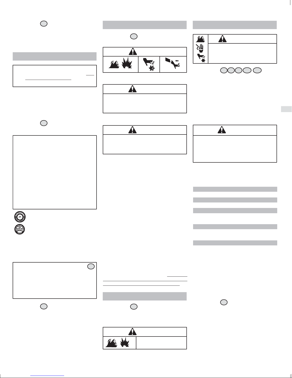
F
VOIR FIG.
5
Basculer le moteur selon l’angle indiqué pour remplir
correctement le réservoir.
Laisser environ 4 cm d’espace sous le haut du col pour
permettre la dilatation du carburant. Ne pas trop
remplir. Remettre le bouchon du réservoir en place.
HUILES RECOMMANDEES
DANGER
Le moteur est expédié par Briggs & Stratton sans
huile. Avant de lancer le moteur, faire le plein
d’huile. Eviter de trop remplir.
CONTENANCE EN HUILE : 90 ml (3 oz)
Utiliser une huile détergente de haute qualité, classée
SH, SJ ou supérieure. Ne pas employer d’additifs
spéciaux avec les huiles recommandées. Ne pas
mélanger d’huile à l’essence. Choisir la viscosité de
l’huile dans le tableau.
VOIR FIG.
ATTENTION : L’huile SAE 30 utilisée en
dessous de 10° C (50° F) rendra les
démarrages difficiles et risque
d’endommager l’alésage en raison de la
mauvaise lubrification.
* ATTENTION : Il faut utiliser une huile
synthétique quand le moteur fonctionne en
dessous de 4
d’endommager le moteur.
** ATTENTION : Les moteurs refroidis par air
chauffent plus que les moteurs
automobiles. L’utilisation d’une huile non de
synthèse à multi−viscosité (5 W 30, 10 W 30,
etc.) à des températures supérieures à 4° C
entraînera une consommation d’huile
supérieure à la normale.
VERIFICATION OU COMPLEMENT D’HUILE
ATTENTION : VOIR FIG.
Pour vérifier l’huile, le moteur doit être horizontal
et l’orifice de remplissage d’huile dirigé vers le haut.
S’il n’est pas horizontal, la lecture de la jauge ne sera
pas précise et risque d’entraîner une erreur de
remplissage. Cela peut éventuellement endommager
le moteur.
VOIR FIG.
• Enlever la jauge pour rajouter de l’huile .
• Après avoir retiré la jauge à huile, l’essuyer avec
un linge propre, la replacer et la serrer de nouveau.
• Retirer la jauge à huile et contrôler le niveau
d’huile. Le niveau d’huile doit atteindre la marque
FULL .
• S’il faut rajouter de l’huile, le faire lentement
Utiliser la timbale de mesure d’huile. Ne rajouter
que 1 oz.
2
° C, sous peine
L’huile de synthèse répondant aux spécifications
des normes ILSAC GF−2, comportant la marque
de certification API et le symbole d’entretien API
(montré à gauche) avec SJ/CF ENERGY
CONSERVING" ou supérieure, est une huile
acceptable à toutes les températures. L’utilisation
d’une huile de synthèse ne modifie en rien les
périodes de changement d’huile préconisées.
3
4
à 0,5 oz. d’huile à la fois.
.
DEMARRAGE
VOIR FIG.
Vérifier le niveau d’huile avant de démarrer le
moteur : il doit être à la marque FULL de la jauge. Si
le moteur est démarré sans huile, il sera endom−
magé.
Le fait de faire fonctionner le moteur à un régime
excessif sans qu’il soit en charge peut l’endom−
mager. Ne pas utiliser un coupe−bordures à fil avec
un fil inférieur à 25 cm de diamètre.
DEMARRAGE DU MOTEUR
• Vérifier le niveau d’huile.
• Ajouter de l’essence et remettre le bouchon du
réservoir en place.
• Mettre l’appareil sur une surface plane.
• Appuyer
UN MOTEUR NEUF, 8 fois pour les démarrages
ultérieurs.
• Le levier du starter
.
fond
• Serrer la gâchette d’accélération
poignée du lanceur
le moteur démarre.
• Attendre 10 secondes au maximum et repousser
le levier du starter à MI−COURSE
• Attendre 20 secondes au minimum puis repousser
le starter en position OFF
• Relâcher la gâchette d’accélération.
DEMARRAGE D’UN MOTEUR CHAUD
6
ATTENTION
ATTENTION
ATTENTION
sur la poire d’amorçage 15 fois POUR
doit être en position starter à
et tirer la
fermement jusqu’à ce que
.
.
H Suivre les indications de démarrage, sauf en ce qui
concerne la gâchette d’accélération. Il n’est pas
nécessaire de serrer ni de tenir la gâchette
d’accélération pour redémarrer un moteur chaud.
ARRÊT
VOIR FIG.
• Appuyer sur le bouton d’arrêt pour arrêter le
moteur.
6
ATTENTION
NE PAS utiliser (fermer) le
starter pour arrêter le moteur.
ENTRETIEN
ATTENTION
Pour prévenir un démarrage
accidentel, retirer le fil de bougie et
le mettre à la masse avant d’effectuer
l’entretien.
VOIR FIG.
7 8 9
10 11
Un entretien régulier améliore les performances et
augmente la durée de vie du moteur. Si les conditions
de fonctionnement sont défavorables, il est
recommandé d’entretenir le moteur plus fréquemment.
Contacter un Réparateur Agréé Briggs & Stratton pour
obtenir les pièces détachées adéquates. Les pièces de
rechange autres que celles d’origine peuvent ne pas
fonctionner aussi bien, risquent d’endommager le
moteur et peuvent entraîner des blessures ou
l’annulation de la garantie.
ATTENTION
Ne pas frapper sur le volant moteur avec un
marteau ou un objet dur. Sinon le volant moteur
risque d’éclater durant le fonctionnement.
Ne pas modifier les ressorts du régulateur ou autres
pièces pour augmenter le régime du moteur.
Respecter les intervalles horaires ou calendaires,
selon le cas. Un entretien plus fréquent est
nécessaire lors d’une utilisation dans des conditions
difficiles indiquées ci−dessous.
Avant chaque utilisation
D Contrôler le niveau d’huile
Pendant les 4 premières heures
D Changer l’huile
Toutes les 8 heures ou chaque saison
D Changer l’huile
D Entretenir le filtre à air *
Toutes les 50 heures ou chaque saison
D Remplacer le filtre à essence
D Remplacer la bougie**
Chaque saison
D Vérifier le jeu de soupapes
* Nettoyer plus souvent dans des conditions
poussiéreuses, en présence de débris aériens ou après
une utilisation prolongée pour couper des herbes hautes
et sèches.
** Dans certains pays, la législation impose l’emploi de
bougies à résistance pour supprimer les parasites de
l’allumage. Si ce moteur était équipé d’une bougie avec
résistance, utiliser le même type de bougie lors de son
remplacement.
ENTRETIEN DE L’HUILE
VOIR FIG.
Faire la vidange d’huile quand le moteur est chaud,
s’assurer que le bouchon d’essence est bien serré.
Retirer la jauge à huile et vidanger l’huile comme
illustré.
Mettre le moteur à l’horizontale. Retirer la jauge à huile.
Avec la timbale graduée, verser lentement l’huile en
ajoutant 14 ml (0,5 oz.) à la fois . NE PAS TROP
REMPLIR.
Voir la procédure de remplissage au Chapitre Huiles
recommandées.
7
27
Page 18

F
ENTRETIEN DU FILTRE À AIR
VOIR FIG.
Remplacer l’élément de filtre en mousse Oil Foam"
s’il est très sale ou endommagé.
• Appuyer sur la patte du couvercle
détacher le couvercle. Le retirer du moteur pour
atteindre le filtre à air.
• Nettoyer la poussière de la chambre d’admission.
• Laver l’élément en mousse Oil Foam dans de
l’eau additionnée de détergent liquide. Sécher
l’élément en le pressant dans un chiffon propre.
Saturer
Oil Foam, puis le presser dans un chiffon propre
pour éliminer l’excès d’huile.
• Le moteur fumera si on laisse trop d’huile sur le
filtre.
DANGER
Ne pas utiliser d’air comprimé ni de solvant pour
nettoyer le filtre à air. L’air comprimé peut endom−
mager le filtre, les solvants le dissoudre.
8
pour
d’huile moteur l’élément en mousse
ENTRETIEN DES BOUGIES
VOIR FIG.
• Les électrodes de la bougie doivent être propres
avec des électrodes en bon état pour produire une
forte étincelle. Plus la bougie est usée ou sale, plus
il est difficile de démarrer le moteur. Remplacer la
bougie chaque saison.
• L’écartement des électrodes de bougie doit être de
0,64 mm.
9
ATTENTION
NE PAS contrôler l’étincelle avec la
bougie retirée. Utiliser seulement le
testeur Briggs & Stratton, pour contrô−
ler l’étincelle. NE PAS faire tourner le
moteur avec la bougie enlevée.
FILTRE À ESSENCE DANS LE RÉSERVOIR
VOIR FIG.
Les pièces de rechange du système
d’alimentation (bouchons, Durits, réservoirs,
filtres, etc.) doivent être d’origine, sous peine de
provoquer un incendie.
DANGER
Le filtre doit être bien fixé sur la Durit d’arrivée
d’essence
endommager votre moteur.
10
ATTENTION
Vidanger le réservoir d’essence avant de
remplacer le filtre à carburant. Dans le
cas contraire, l’essence peut fuir et créer
un risque d’incendie / d’explosion.
. Un filtre fixé à la mauvaise Durit peut
GARDER LE MOTEUR PROPRE
Éliminer périodiquement l’accumulation d’herbe et de
paille du moteur. Nettoyer le protège−doigts.
Ne pas asperger le moteur d’eau pour le nettoyer pour
éviter de contaminer le carburant. Le nettoyer avec une
brosse ou à l’air comprimé.
ATTENTION
Il faut que le moteur reste propre pour
réduire le risque de surchauffe et
d’inflammation des débris accumulés.
Nettoyer le moteur quand il est froid.
REGLAGES
RÉGLAGE DU CARBURATEUR
VOIR FIG.
11
PRUDENCE
Le fabricant de l’équipement sur lequel est monté
ce moteur a spécifié le régime maximum à vide
d’utilisation du moteur. NE PAS DEPASSER ce
régime maximum.
Le carburateur de ce moteur est à faibles émissions. La
vis de réglage du ralenti est réglée en usine.
POUR REGLER LE CARBURATEUR ET LA VIS DE
RALENTI
• Lancer le moteur et le faire chauffer pendant
5 minutes environ avant réglage.
• Dés que le moteur tourne, lâcher la commande
d’accélération.
• Utiliser un compte−tours (B&S Réf. 19389) pour
vérifier le ralenti.
• Mettre le levier d’accélération
réglage du ralenti
• Tourner la vis dans le sens horaire pour augmenter
le régime et dans le sens anti−horaire pour le
diminuer. Régler la vis de ralenti pour obtenir
4 000 tr/min au minimum.
• Relâcher le levier d’accélération. Serrer la
commande d’accélération pour accélérer le
moteur. Il doit fonctionner en douceur.
et l’y maintenir.
contre la vis de
STOCKAGE
Les moteurs stockés pendant plus de 30 jours doivent
faire l’objet d’attentions spéciales.
Pour prévenir les dépôts de gomme dans le système
d’alimentation ou sur des pièces essentielles du
carburateur :
a) Si le réservoir contient une essence reformulée ou
oxygénée (essence mélangée à un alcool ou un éther),
faire tourner le moteur jusqu’à ce qu’il s’arrête par
manque d’essence ou b) si le réservoir contient de
l’essence, faire tourner le moteur jusqu’à ce qu’il
s’arrête par manque d’essence ou ajouter un
stabilisateur d’essence dans le réservoir.
Remarque : Si on utilise un stabilisateur, faire tourner
le moteur pendant plusieurs minutes pour faire circuler le
stabilisateur dans le carburateur. Le moteur et l’essence
peuvent alors être remisés.
1. Changer l’huile.
2. Retirer la bougie et verser environ 15 ml d’huile
moteur dans le cylindre. Remonter la bougie et
faire tourner lentement le moteur pour répartir
l’huile.
3. Bien retirer les débris du moteur.
4. Ranger dans un endroit propre et sec.
Nous recommandons l’emploi du stabilisateur de
carburant Briggs & Stratton disponible chez tout
Réparateur Agréé Briggs & Stratton.
ATTENTION
NE PAS stocker le moteur à proximité d’un
poêle, d’une chaudière ou d’un
chauffe−eau qui utilise une veilleuse ou
tout dispositif pouvant produire des
étincelles.
ENTRETIEN
S’adresser à un Réparateur Agréé Briggs & Stratton.
Ils disposent tous d’un stock de pièces de rechange
d’origine Briggs & Stratton et sont équipés de
l’outillage spécial. Les mécaniciens expérimentés
assurent un entretien et une réparation de qualité
pour tous les moteurs Briggs & Stratton. Seuls les
« Réparateurs Agréés Briggs & Stratton » sont tenus
de respecter les normes Briggs & Stratton.
Extrait de la liste des pièces d’origine
Huile 100005 E. . . . . . . . . . . . . . . . . . . . . . . . . .
Huile de synthèse 100074. . . . . . . . . . . . . . . . . . .
Kit de pompe à huile 005056B. . . . . . . . . . . . . . . .
(utilise une perceuse électrique standard pour
vidanger rapidement l’huile du moteur)
Additif pour essence 992030 ou 999005E. . . . . . .
Filtre à carburant 696918. . . . . . . . . . . . . . . . . . .
Durit d’essence 696935. . . . . . . . . . . . . . . . . . . . .
Mousse du filtre à air 696923. . . . . . . . . . . . . . . . .
Bougie à résistance 696876. . . . . . . . . . . . . . . . . .
Contrôleur d’étincelle 019368. . . . . . . . . . . . . . . . .
Clé à bougies 089838 ou 005023B. . . . . . . . . . . .
Manuel de réparation en Anglais 275072. . . . . . . . .
Pour acheter ou voir les autres produits disponibles
auprès de Briggs & Stratton, s’adresser à un
Réparateur Agréé Briggs & Stratton. Visiter notre site
Internet
www.briggsandstratton.com pour
connaître le concessionnaire le plus proche de chez
vous ou consulter les Pages Jaunes.
Besoin d’aide ? Consultez notre site Internet ou
appelez le 1−800−233−3723 (Etats−Unis et Canada)
où le menu de messages pré−enregistrés vous
communiquera des informations relatives à
l’entretien des moteurs.
Briggs & Stratton
Le logo des « doigts qui marchent » et les Pages jaunes
sont des marques déposées dans plusieurs pays.
28
Page 19

F
Déclaration de garantie du système de contrôle des
émissions de Briggs & Stratton Corporation (B&S),
du California Air Resources Board (CARB) et de la
United States Environmental Protection Agency
(U.S. EPA) (Droits et obligations du propriétaire au
titre de la garantie contre tout défaut)
LA COUVERTURE DE LA GARANTIE DES CONTRÔLES
D’EMISSIONS EST APPLICABLE AUX MOTEURS
CERTIFIES ACHETES EN CALIFORNIE À PARTIR DE 1995
ET UTILISES EN CALIFORNIE ET AUX MOTEURS
CERTIFIES ACHETES À PARTIR DE 1997 ET UTILISES
AILLEURS AUX ETATS−UNIS (ET APRÈS LE 1ER JANVIER
2001 AU CANADA).
Déclaration de garantie pour les défauts de contrôle
d’émissions pour la Californie, les Etats−Unis et le
Le California Air Resources Board (CARB), U.S. EPA et B&S
ont le plaisir de vous expliquer la garantie du système de
contrôle des émissions pour votre moteur non routier fabriqué
depuis 2000. En Californie, les nouveaux petits moteurs tout
terrain doivent être conçus, fabriqués et équipés pour
répondre aux normes sévères antibrouillard de l’état. Ailleurs
aux Etats−Unis, les nouveaux moteurs à allumage
commandés depuis l’année modèle 1997 doivent répondre à
des normes semblables édictées par la U.S. EPA.
Briggs & Stratton doit garantir le système de contrôle des
émissions de votre moteur pendant les durées indiquées
ci−après, en supposant que le moteur non routier ne soit pas
mal utilisé, négligé ou que son entretien ne soit pas
défectueux.
Le système de contrôle des émissions comprend des pièces
comme le carburateur, le filtre à air, le système d’allumage, le
silencieux et le convertisseur catalytique. Des connecteurs et
d’autres assemblages impliqués dans les émissions peuvent
aussi en faire partie.
Si la condition de garantie est remplie, Briggs & Stratton
réparera gratuitement votre moteur y compris le diagnostic,
les pièces et la main−d’œuvre.
Couverture de la garantie de défectuosité du contrôle
des émissions de Briggs & Stratton
Les petits moteurs tout terrain sont garantis en ce qui
concerne les défauts des pièces du contrôle d’émission
pendant une période de deux ans, aux conditions énoncées
plus loin. Si une pièce de votre moteur couverte par cette
garantie est défectueuse, Briggs et Stratton la réparera ou la
remplacera.
Responsabilités du propriétaire au titre de la garantie
En tant que propriétaire d’un petit moteur non routier, vous
êtes responsable de l’entretien nécessaire indiqué dans les
instructions de fonctionnement et d’entretien.
Briggs & Stratton recommande de conserver toutes les
factures de maintenance de votre moteur, mais
Briggs & Stratton ne peut renier la garantie uniquement à
cause de l’absence de factures.
En tant que propriétaire d’un moteur non routier, vous devez
néanmoins savoir que Briggs & Stratton peut refuser
d’appliquer la garantie si la défectuosité de votre moteur ou
d’une partie de ce moteur est due à un abus, une négligence,
un entretien non correct ou des modifications non
approuvées.
Vous avez la responsabilité de confier votre moteur à un
Réparateur Agréé Briggs & Stratton dès que vous découvrez
un problème. Les réparations incontestables sous garantie
seront effectuées en un temps raisonnable qui ne doit pas
excéder 30 jours.
Si vous avez des questions au sujet de vos droits ou de vos
responsabilités quant à la garantie, veuillez contacter un
représentant de Briggs & Stratton au 1−414−259−5262.
La garantie d’émission est une garantie contre des
défectuosités. Les défectuosités sont jugées en fonction des
performances normales d’un moteur. La garantie n’est pas
liée à un test d’émission en fonctionnement.
Canada.
Dispositions de la garantie de défectuosité du
contrôle des émissions de Briggs & Stratton
Suivent les dispositions particulières de la couverture de la
garantie de défectuosité du contrôle des émissions. Elles
viennent en complément de la garantie des moteurs Briggs et
Stratton pour les moteurs non réglementés qui se trouve dans
les instructions de fonctionnement et d’entretien.
1. Pièces garanties
La couverture au titre de cette garantie ne s’étend qu’aux
pièces énumérées ci−dessous (celles du système de
contrôle des émissions) dans la mesure où ces pièces
étaient présentes dans le moteur au moment de l’achat.
a. Système de dosage du carburant
• Système d’enrichissement pour démarrages à
froid (starter)
• Carburateur et pièces internes
• Pompe à carburant
b. Système d’admission d’air
• Filtre à air
• Collecteur d’admission
c. Système d’allumage
• Bougie(s)
• Système d’allumage par volant magnétique
d. Système catalytique
• Convertisseur catalytique
• Collecteur d’échappement
• Système d’injection d’air ou soupape d’impulsion
e. Pièces diverses utilisées dans les systèmes
ci−dessus
• Soupapes et contacteurs de dépression, de
température, de position et de durée.
• Raccords et assemblages
2. Durée de la couverture
Briggs & Stratton garantit au propriétaire initial et à tous
les acheteurs suivants les pièces contre tout défaut de
matière ou de fabrication qui pourrait entraîner une
défectuosité des pièces garanties pendant une période
de deux ans à partir de la date de livraison du moteur à un
acheteur individuel.
3. Gratuité
La réparation ou le remplacement de toute pièce garantie
s’effectuera gratuitement pour l’acheteur, y compris les
frais de diagnostic permettant de déterminer qu’une pièce
garantie est défectueuse, si le diagnostic est effectué par
un Réparateur Agréé Briggs & Stratton. Pour bénéficier
du service de garantie, veuillez contacter le Réparateur
Agréé Briggs & Stratton le plus proche de chez vous listé
dans les Pages Jaunes sous la rubrique « moteurs,
essence », « moteurs à essence », « tondeuses à gazon »
ou autre catégorie semblable.
4. Réclamations et exclusions de garantie
Les réclamations sous garantie seront présentées selon
les dispositions de la police de garantie des moteurs de
Briggs & Stratton. La garantie ne couvre pas les pièces
qui ne sont pas des pièces Briggs & Stratton d’origine ou
qui ont fait l’objet d’abus, de négligence ou d’un mauvais
entretien ainsi qu’indiqué dans la police de garantie des
moteurs de Briggs & Stratton. Briggs & Stratton n’est pas
responsable des défaillances dues à l’utilisation de
pièces rajoutées, non d’origine ou modifiées.
5. Entretien
Toute pièce garantie qui ne doit pas être remplacée au
titre de l’entretien ou qui est sujette à une inspection
régulière avec la mention « réparer ou remplacer si
besoin est » est garantie contre tout défaut pendant la
période de garantie. Toute pièce dont le remplacement
est prévu au titre de l’entretien n’est garantie contre tout
défaut que pendant sa période normale d’utilisation. Les
opérations de maintenance et de réparation doivent
utiliser des pièces équivalentes sur le plan des
performances et de la longévité. Le propriétaire est
responsable de l’entretien défini dans les instructions de
fonctionnement et d’entretien de Briggs & Stratton.
6. Couverture des conséquences
La présente couverture s’étend à la défaillance de tout
composant du moteur due à la défaillance d’une pièce
encore sous garantie.
Consultez les informations sur la
période de durabilité des émissions
et l’indice d’air sur l’étiquette
d’émissions de votre moteur
Les moteurs qui sont certifiés conformes aux normes
d’émissions du California Air Resources Board (CARB)
Phase 2 doivent afficher l’information concernant la période
de durabilité des émissions et l’indice d’air. Cette information
est indiquée sur les étiquettes apposées sur les moteurs par
Briggs & Stratton. L’étiquette du moteur indique les
informations de certification.
La période de durabilité des émissions indique le nombre
d’heures d’utilisation normale pour lequel le moteur est certifié
conforme aux normes d’émissions sous réserve d’un
entretien approprié tel qu’indiqué dans le manuel d’utilisation
et d’entretien. Les catégories suivantes sont utilisées :
Modéré : le moteur est certifié conforme pour
125 heures d’utilisation normale.
Intermédiaire :le moteur est certifié conforme pour
250 heures d’utilisation normale.
Prolongé : le moteur est certifié conforme pour
500 heures d’utilisation normale.
Par exemple, une tondeuse à gazon autonome de modèle
standard est utilisée environ 20 à 25 heures par an. Par
conséquent, la période de durabilité des émissions d’un
moteur dans la catégorie intermédiaire pour ce type de
matériel équivaut à 10 ou 12 ans.
L’indice d’air est un nombre qui décrit le niveau relatif
d’émissions pour une famille spécifique de moteurs. Plus
l’indice d’air est bas, plus le moteur est écologique. Cette
information est indiquée sous forme graphique sur l’étiquette
d’émissions.
Dans l’état de Californie, les moteurs de la série 120000
couverts par ce manuel ont reçu du California Air Resources
Board la certification de conformité aux normes antipollution
pour 125 heures de fonctionnement. Cette certification
n’accorde aucune garantie supplémentaire de
fonctionnement ou de durée de vie pour ce moteur à son
acheteur, propriétaire ou utilisateur. La garantie de ce moteur
ne couvre que le produit et ses émissions certifiées indiquées
par ailleurs dans ce manuel.
À compter du 1er juillet 2000, il faut
surveiller la période de conformité
d’émissions sur les étiquettes
Après le 1er juillet 2000, certains moteurs Briggs & Stratton
seront certifiés conformes aux normes environnementales
d’émissions de la United States Environmental Protection
Agency (USEPA) Phase 2, Classe IV. Pour les moteurs
certifiés Phase 2, Classe IV, la période de conformité
d’émissions mentionnée sur les étiquettes indique le nombre
d’heures d’utilisation pour lequel le moteur est en conformité
avec les normes fédérales. Pour les moteurs de cylindrée
inférieure à 225 cm3, la catégorie C = 125 heures,
B = 250 heures et A = 500 heures. Pour les moteurs de plus
de 225 cm3, la catégorie C = 250 heures, B = 500 heures et
A = 1000 heures.
La cylindrée des moteurs Modèle 21000 est de 34 cm3.
La cylindrée des moteurs Modèle 21100 est de 40 cm3.
Ceci est une représentation
générique des étiquettes
d’émissions que vous
retrouverez sur les moteurs
certifiés.
29
Page 20

F
APPLICATION DE LA GARANTIE SUR LES MOTEURS BRIGGS & STRATTON
Date d’effet au 1er janvier 2003, annule et remplace toutes les garanties précédentes et les garanties antérieures au 1er janvier 2003
Briggs & Stratton remplacera ou réparera gratuitement toute pièce ou pièces du moteur présentant un défaut de matière ou de construction ou les deux. Tous les
frais de transport de pièces destinées à être remplacées ou réparées au titre de la présente garantie restent à charge de l’acheteur. Cette garantie est applicable
pendant la période et aux conditions prévues dans le présent document. Pour toute intervention sous garantie, chercher le Réparateur Agréé Briggs & Stratton le
plus proche dans la liste des Réparateurs sur notre site Internet www.briggsandstratton.com ou en appelant le numéro figurant dans les Pages Jaunes.
IL N’EXISTE AUCUNE AUTRE GARANTIE EXPRESSE. LES GARANTIES IMPLICITES, Y COMPRIS CELLES DE LA VALEUR MARCHANDE ET
D’ADAPTATION A UN OBJECTIF PARTICULIER, SONT LIMITEES A UN AN A PARTIR DE LA DATE D’ACHAT OU A LA PERIODE LEGALE ADMISE. TOUTE
AUTRE GARANTIE IMPLICITE EST EXCLUE. NOTRE RESPONSABILITE POUR LES DEGATS PROVOQUES PAR L’EQUIPEMENT OU LES DOMMAGES INTERETS ACCESSOIRES EST EXCLUE DANS LA LIMITE DES EXCLUSIONS AUTORISEES PAR LA LOI. Certains pays ou états n’autorisent pas la limitation
de la durée de la garantie implicite et certains pays ou états n’autorisent pas l’exclusion ou la limitation des dégâts provoqués ou consécutifs à un accident, ce qui
fait que les limitations et exclusions ci-dessus peuvent ne pas s’appliquer à vous. Cette garantie vous donne des droits légaux et vous pouvez bénéficier d’autres
droits qui peuvent varier d’un pays à l’autre ou d’un état à l’autre.
GARANTIE LIMITEE
NOTRE PRODUIT
VANGUARD
ELS
I/Cr
Industrial Plus
Intek
(Chemise en fonte)
Fource
Intek
(Chemise refroidie)
Power Built OHV
QUANTUMr
Quattro
Q45
Sprint
Classic
Etek
PERIODE DE GARANTIE*
Usage privé
2 ans
Usage commercial
* Veuillez noter les périodes de garantie spéciales suivantes : 2 ans pour les moteurs Classic dans les pays de l’Union Européenne et les pays de l’Est, pour tous les produits à usage
privé dans l’Union Européenne et pour les systèmes de contrôle des émissions sur les moteurs certifiés par EPA et CARB. 5 ans pour usage privé, 90 jours pour usage commercial du
La période de garantie débute à la date d’achat par l’acheteur particulier initial ou l’utilisateur professionnel final et continue pendant la période indiquée dans le tableau ci-dessus.
« Usage privé » signifie utilisation pour l’entretien de sa résidence personnelle par un acheteur particulier. « Usage commercial » couvre toutes les autres utilisations, y compris dans un
but commercial, de rentabilité ou de location. Dès qu’un moteur a servi à un usage commercial, il sera considéré comme moteur à usage commercial dans le cadre de la présente
garantie.
UNE CARTE D’ENREGISTREMENT DE LA GARANTIE N’EST PAS EXIGEE POUR BENEFICIER DE LA GARANTIE SUR LES PRODUITS BRIGGS & STRATTON. VOUS
DEVEZ CONSERVER VOTRE FACTURE D’ACHAT. SI VOUS NE FOURNISSEZ PAS LA PREUVE DE L’ACHAT INITIAL AU MOMENT DE L’INTERVENTION SOUS
GARANTIE, LA DATE DE FABRICATION DU PRODUIT SERA UTILISEE POUR DETERMINER LA PERIODE DE GARANTIE.
lanceur Touch-N-Mow sur les moteurs Quantum et Intek. Les moteurs utilisés en compétition ou avec un but d’exploitation commerciale ou de location ne sont pas garantis.
2 ans 2 ans
1 an
90 jours
1 an
90 jours
1 an
A PROPOS DE LA GARANTIE DE MOTEUR
Briggs & Stratton se fera un plaisir d’effectuer une réparation en
garantie tout en déplorant les inconvénients qu’elle peut vous
occasionner. Tout Réparateur Agréé peut effectuer des réparations
en garantie. La plupart des réparations en garantie sont effectuées
sans discussion mais il peut arriver que la demande de réparation en
garantie soit injustifiée. Par exemple, la garantie ne s’applique pas
quand la défaillance du moteur est due à un abus, un manque
d’entretien courant, l’expédition, la manutention, l’entreposage ou
une mauvaise installation. Il en va de même si le numéro de série du
moteur a été éliminé ou que le moteur a été modifié ou trafiqué.
Si le client n’est pas d’accord avec la décision d’un Réparateur
Agréé, une enquête sera effectuée afin de déterminer si la garantie
peut être appliquée. Demander au Réparateur Agréé de soumettre
tous les faits au Grossiste ou à l’usine pour examen. Si le Grossiste
ou l’usine décide que la demande est justifiée, les articles reconnus
défectueux seront intégralement remboursés au client. Afin d’éviter
tout malentendu entre les propriétaires de moteurs et les
Réparateurs Agréés Briggs & Stratton, nous indiquons ci−après
quelques−unes des causes de défaillance des moteurs pour
lesquelles le remplacement ou la réparation n’est pas couvert par la
garantie.
Usure normale:
Les moteurs, comme tous les autres appareils mécaniques, ont
besoin d’un entretien régulier des pièces et leur remplacement pour
fonctionner correctement. La garantie ne couvre pas la réparation
lorsque c’est l’usure normale qui a amené les pièces ou le moteur en
fin de vie.
Entretien inadéquat:
La longévité d’un moteur dépend des conditions dans lesquelles il
est utilisé et de l’entretien qu’il reçoit. Certaines applications, comme
les motoculteurs, les pompes et les tondeuses, sont souvent
utilisées dans un environnement poussiéreux ou sale, ce qui peut
être la cause d’une usure pouvant paraître prématurée. Une telle
usure, lorsqu’elle est consécutive à l’entrée de poussière, sable ou
Les moteurs Briggs & Stratton sont protégés par un ou plusieurs des brevets suivants: Conception D−247.177 (Demandes d’autres brevets déposées)
6,325,036
6,284,123
6,260,529
6,230,678
6,202,616
6,116,212
6,077,063
6,064,027
6,014,808
5,894,715
5,852,951
5,823,153
5,819,513
5,813,384
5,765,713
5,645,025
5,642,701
5,619,845
5,606,948
5,606,851
5,548,955
5,546,901
5,503,125
5,501,203
autre produit abrasif, à cause d’un mauvais entretien, n’est pas
couverte par la garantie.
Cette garantie couvre uniquement
et/ou la main d’œuvre et pas le remplacement ou le
remboursement de l’équipement sur lequel est monté le
moteur. La garantie ne s’applique pas non plus aux réparations
dues a:
1. DES PROBLEMES PROVOQUES PAR L’EMPLOI DE
PIECES NON D’ORIGINE BRIGGS & STRATTON.
2. Les commandes de l’équipement ou les dispositifs qui
empêchent le démarrage, perturbent le fonctionnement du
moteur ou abrègent sa durée de vie. (Contacter le fabricant de
l’équipement.)
3. Les fuites de carburateur, l’obstruction des Durits
d’alimentation, le blocage des soupapes ou autres
dommages provoqués par une essence contaminée ou trop
vieille. (Utiliser de l’essence sans plomb récente et propre et
du stabilisateur pour carburant Briggs & Stratton,
Réf. : 999005E.)
4. Les pièces qui seraient rayées ou cassées du fait du
fonctionnement du moteur avec un manque d’huile ou d’une
huile polluée, ou encore d’un indice de viscosité de l’huile
inadéquat (vérifier le niveau d’huile quotidiennement ou après
8 heures d’utilisation. Refaire le niveau quand c’est
nécessaire et vidanger aux périodes recommandées.) Le
dispositif OIL GARD peut ne pas couper un moteur en
marche. Le moteur peut être endommagé si le niveau d’huile
n’est pas maintenu régulièrement. Lire les Instructions
d’utilisation et d’entretien.
5. La réparation ou le réglage de pièces ou d’un groupe de
pièces associées tels que les embrayages, transmissions,
commandes à distance, etc., qui ne sont pas fabriqués par
Briggs & Stratton.
5,497,679
5,320,795
5,271,363
5,269,713
5,265,700
5,243,878
5,235,943
5,197,425
5,197,422
5,191,864
5,188,069
5,186,142
les pièces défectueuses
5,138,996
5,086,890
5,070,829
5,058,544
5,040,644
5,009,208
6. Les dommages ou l’usure de pièces provoqués par la
pénétration de poussière due au manque d’entretien ou au
mauvais montage du filtre à air ou à l’emploi d’un élément ou
d’une cartouche de filtre à air non d’origine. (Aux intervalles
recommandés, nettoyer et huiler à nouveau le filtre élément
mousse (Oil Foam) ou le pré−filtre en mousse et remplacer
la cartouche.) Lire les instructions d’utilisation et d’entretien.
7. Les pièces endommagées suite à un sur−régime ou une
surchauffe provoquée par l’obstruction des ailettes de
refroidissement et de la zone du volant par des débris d’herbe
ou de la poussière ou par l’utilisation du moteur dans un local
fermé insuffisamment ventilé. (Nettoyer aux intervalles
recommandés les ailettes du cylindre, de la culasse et du
volant.) Lire les instructions d’utilisation et d’entretien.
8. Le bris de pièces du moteur ou de l’équipement dû à des
vibrations excessives résultant d’un serrage insuffisant des
boulons de fixation du moteur, d’une lame ou d’une turbine
desserrée ou mal équilibrée, d’une mauvaise adaptation de
l’équipement sur le vilebrequin du moteur, d’un sur−régime ou
d’une mauvaise utilisation.
9. Vilebrequin faussé ou cassé suite au choc de la lame d’une
tondeuse rotative sur un corps dur, ou d’une courroie
trapézoïdale trop tendue.
10. Réglage ou mise au point normale du moteur.
11. La défaillance du moteur ou des pièces du moteur, telles que
la chambre de combustion, les soupapes, sièges de soupape,
guides de soupape ou bobinage du démarreur grillés, suite à
l’emploi de carburants de substitution tels que du pétrole
liquéfié, du gaz naturel ou des essences modifiées, etc.
La garantie peut être appliquée uniquement par les Stations
Service Agréées Briggs & Stratton. La Station service la plus
proche figure dans les Pages Jaunes" de votre annuaire
téléphonique, sous la rubrique moteurs à essence",
tondeuses à gazon" ou sous une rubrique apparentée.
4,996,956
4,977,879
4,971,219
4,895,119
4,819,593
4,719,682
4,633,556
4,630,498
4,522,080
4,520,288
4,512,499
4,453,507
4,430,984 DES. 308,871
DES. 308,872
DES. 309,457
DES. 356,951
DES. 361,771
DES. 375,963
30
Page 21

Fig. 5
➎
➋
➌
➏
Fig. 6
➐
➊
➊
➍
➑
➋
Fig. 7 Fig. 8
➋
➌
➌
➋
Page 22

(Cette page ne s’applique que pour le Canada et les Etats--Unis)
La Corporation Briggs & Stratton (B&S), le California Air Resources Board (CARB)
LA GARANTIE SUR LE SYSTÈME D’ÉCHAPPEMENT EST APPLICABLE SUR LES MOTEURS
CERTIFIÉSACHETÉS EN CALIFORNIE EN 1995 ET LES ANNÉES SUIVANTESET QUI SONT UTI-
Le California Air Resources Board (CARB), le Bureau américain de protection environnementale
(U.S. EPA)et B& S sont heureux d’expliquer la garantie sur le système d’échappement des petits
moteurs hors--route de votre modèle 2000 et des années ultérieures (SORE). En Californie, les
nouveaux petits moteurs hors route doivent être conçus, construits et équipés pour rencontrer les
standards rigoureux d’antipollution. Ailleurs aux Etats--Unis, les nouveaux moteurs hors route à
bougie d’allumage certifiés pour les modèles de 1997 et plus, doivent rencontrer des normes similaires mises de l’avant par le U.S. EPA.Briggs & Stratton garantit le système de contrôle d’échap-
Lespetits moteurs horsroute sont garantiscontre ladéfectuosité des piècesdu système decontrôled’échappement pour unepériodede 2 ans,sujette aux conditionsstipuléesci--contre.Si n’impor-
Entant que propriétaire d’un petit moteur hors route, vous êtes responsable de veiller à l’exécution
de l’entretien requis t el que stipulé dans votre manuel d’opération et d’entretien. B&S vous recommande de conserver tous les reçus couvrant les travaux d’entretien de votre petit moteur hors route, mais B&S ne peut refuser la garantie en raison d’absence de reçus ou pour défaut d’avoir suivi
tout l’échéancier du programme d’entretien.
Entant que propriétaire d’un petitmoteur hors route, vous devezêtre informé queB&S peut refuser
d’honorercette garantie sila défectuositéde votre moteurou d’une partie de votremoteur est dueà
un emploi abusif, une négligence, un entretien incorrect ou une modification non approuvée.
Ce qui suit concerne les dispositions spécifiques relativement à votre garantie sur le système de contrôle d’échappement. C’est une addition à la garantie B&S pour les moteurs non réglementés contenue
dans le manuel d’entretien et d’utilisation.
1. Pièces sous garantie
La couverture de cette garantie ne s’applique que sur les pièces listées ci--contre (les parties
dusystème decontrôle d’échappement) dans la mesure où cespièces étaientprésentes surle
moteur au moment de l’achat.
Garantie sur le système d’échappement (Garantie contre les défectuosités, droits et obligations du propriétaire)
Déclaration de garantie sur le système d’échappement pour la Californie, les Etats- Unis et le Canada
Couverture de garantie Briggs & Stratton contre toute défectuosité du système de contrôle d’échappement
a. Système de dosage du carburant
• Système d’enrichissement de démarrage à froid
• Carburateur et parties internes
• Pompeàessence
b. Système d’induction d’air
• Filtre à air
• Tubulure d’admission
c. Système d’ignition
• Bougies d’allumage
• Système d’allumage électromagnétique
d. Système catalyseur
• Convertisseur catalytique
• Collecteur d’échappement
• Système d’injection d’air ou à pulsion
e. Autres pièces utilisées dans les systèmes ci--haut mentionnés
• Soupapes et interrupteurs de dépression, de température, de position.
• Connecteurs et assemblages.
2. Duréedelacouverture
B&S garantit le propriétaire initial et tous les acheteurs subséquents que les pièces sous garantiesont exemptes devicede matière oude fabrication quipourraient causer desdéfectuosi-
tés des pièces sous garantie pour une période de deux ans à partir de ladate à laquelle le moteur a été livré à l’acheteur.
et le Bureau de protection environnementale des Etats- Unis (US EPA)
LISÉS EN CALIFORNIE, AINSI QU’AUX MODÈLES CERTIFIÉS DE 1997 ET LES ANNÉES SUIVANTES QUI ONT ÉTÉ ACHETÉS ET UTILISÉS AILLEURS AUX ETATS--UNIS ET AU CANADA.
pement de votre moteur pour la période de temps mentionnée ci--contre, sauf s’il a fait l’objet
d’abus, de négligence ou d’un entretien inapproprié.
Votresystème de contrôle d’échappementcomprend despièces telles que le carburateur,lefiltre à
air,le système d’ignition, le silencieux et le convertisseur catalytique. Il peut aussi comprendre les
connecteurs et autres pièces reliées à l’émission.
Lorsqu’ily a conditionà garantie,B&S réparera gratuitementvotre petitmoteur hors--route incluant
le diagnostic, les pièces et la main d’œuvre.
te quelle pièce de votre moteur couverte par cette garantie est défectueuse, elle sera réparée ou
Responsabilités du propriétaire
remplacée par B&S.
Vous avez la responsabilité d’apporter votre petit moteur hors route à un détaillant autorisé B&S
aussitôtque survientun problème.Les réparationssous garantiedoivent être complétées dans un
délai raisonnable ne devant pas excéder 30 jours.
Si vous avez des questions relativement à votre garantie, vos droits et responsabilités, veuillez
communiquer avec un représentant de service B&S au numéro 1--414--259--5262.
La garantie du système d’échappement est une garantie contre les défectuosités. Les défectuosités sont jugées en fonction d’une utilisation normale du moteur. La garantie n’est pas reliée à un
test d’échappement effectué à l’intérieur.
Dispositions de la garantie du système d’échappement Briggs & Stratton
3. Aucuns Frais
La réparation ou le remplacement de toute pièce sous garantie sera effectuée sans aucuns
frais pour le propriétaire, incluant les frais de main d’œuvre pour le diagnostic afin de déterminer si la pièce sous garantie est défectueuse, conditionnel à ce que le diagnostic soit effectué
chezun détaillantautorisé B&S.Pour lagarantie relativeau systèmed’échappement, communiquez avec le détaillant autorisé B&S le plus proche tel que listé dans les pages jaunes de
votre localité sous la rubrique moteur à essence, tondeuse ou autre catégorie similaire.
4. Réclamations et exclusions de la couverture.
Les réclamations de garantie doivent être complétées en accord avec les dispositions de la
politique de garantie B&S. La garantie ne couvre pas les défectuosités de pièces qui ne sont
pas des pièces d’origine B&S ou dans le cas d’abus, négligence ou d’un entretien inapproprié.
La garantie B&S ne couvre pas les défectuosités de pièces sous garantie qui ont fait l’objet
d’ajouts, ont été modifiées ou de pièces qui ne sont pas des pièces B&S d’origine.
5. Entretien
Toutepièce sous garantie qui n’est pas remplacée au moment requis selon le manuel d’entre-
tien ou qui est planifiée seulement pour une inspection régulière sous la mention « réparer ou
remplacer si nécessaire » est garantie contre toute défectuosité pour la période de garantie.
Toutepièce sous garantie qui est planifiée pour un remplacement tel que requis dans l’entretien est garantie contretoute défectuosité seulement pour la période de temps qui va jusqu’au
premier remplacement prévu pour cette pièce. Toutepièce de remplacement équivalente en
performance et durabilité peut être utilisée pour l’entretien ou la réparation. Le propriétaire est
responsable de l’exécution de tout entretien requis tel que défini dans le manuel d’instruction
B&S sur l’entretien et la réparation.
6. Couverture indirecte
La couverture ci--contre s’étend à toute défectuosité des composantes du moteur causée par
ladéfectuosité de n’importe quelle pièce couverte par la garantie et dont la garantieest encore
en vigueur.
Les moteurs qui sont certifiés conformes aux normes standards d’émission du California Air Resources Board (CARB) Tier 2, doivent afficher l’information concernant la période de durabilité du système
d’émission et l’INDICE d’air. Cette information est indiquée sur les étiquettes apposées sur les moteurs par Briggs & Stratton. L’étiquette du moteur indiquera les renseignements concernant la certification.
Lapériodede durabilité d’émission indiquelenombre d’heures d’utilisation normalepourlequel le moteurestcertifié conforme aux normesd’émissionsous réserve d’unentretienapproprié tel qu’indiquédans
le manuel d’opération et d’entretien. Les catégories suivantes sont utilisées :
Modéré le moteur est certifié conforme pour 125 heures d’utilisation normale.
Intermédiaire le moteur est certifié conforme pour 250 heures d’utilisation normale.
Prolongé le moteur est certifié conforme pour 500 heures d’utilisation normale.
Parexemple, unetondeuse demodèle standard est utilisée environ 20 à 25 heures par année. Par conséquent,la périodede durabilitéd’émission d’un moteur dans lacatégorie intermédiaire pour ce typede
tondeuse équivaut à 10 à 12 ans.
L’indice d’air est un nombre qui décrit le niveau relatif d’émission pour une catégorie spécifique de moteur. Plus l’indice d’air est bas, plus le moteur est écologique. Cette information est indiquée sous une
forme graphique sur l’étiquette d’émission.
À compter du 1erjuillet 2000, surveillez la période de conformité d’émission sur les étiquettes
Après le 1erjuillet 2000, certains moteurs B&S seront certifiés conformes aux normes environnementales d’émission standard du United States Environmental Protection Agency (US EPA)Phase 2. Pour les
moteurs certifiés pour la Phase 2, la période de conformité d’émission mentionnée sur les étiquettes indique le nombre d’heures d’utilisation pour lequel le moteur rencontre les normes fédérales. Pour les
moteurs de force moindre que 225 cc, la catégorie C = 125 heures, B = 250 heures et A = 500 heures. Pour les moteurs de 225 cc et plus, la catégorie C = 250 heures, B = 500 heures et A = 1000 heures.
Le remplacement du moteur portant le modèle de série 021000 est 34 cc. Le remplacement du moteur portant le modèle de série 021100 est 40 cc.
INFORMATIONS IMPORTANTES
CORPORATION BRIGGS & STRATTON
Consultez les informations sur la période de durabilité d’émission et l’INDICE d’air sur l’étiquette d’émission de votre moteur
Ceci est une représentation des étiquettes d’émission
que vous retrouverez sur les moteurs certifiés :
FAMILLEYBSXS.3192VA 274812
CE MOTEUR EST CONFORME AUX NORMES
ANTIPOLLUTION2000 --2001 DE CALIFORNIE
POUR LES PETITS MOTEURS HORS ROUTE ET
AUX NORMES ENVIRONNEMENTALES
AMÉRICAINES (EPAPHASE 2) POUR LES
PETITS MOTEURS HORS ROUTE. CONSULTEZ
LE MANUEL DU PROPRIÉTAIRE POUR LES
SPÉCIFICATIONS, L’ENTRETIEN ET L ES
AJUSTEMENTS. CONFORME À LA PÉRIODE
D’ÉMISSION EPA : CATÉGORIE : C
 Loading...