

Brickcom NR-8216-RM User Manual

Product name:
NVR v1.0.0.x Release Date:
2014/
4/30
Manual Revision:
V1.0 Web site:
Email:
suppo
rt@brickcom.com
©20
13 Brickcom Corporation. All Rights Reserved
Network Video Recorder
User Manual
www.brickcom.com
info@brickcom.com
00101

Table of Contents
Chapter 1. Introduction .................................................................................. 4
Hardware Description ............................................................................................ 5
NR-1104 ........................................................................................ 5
NR-2104 / NR-2108 / NR-2116 ...................................................... 6
LED Indicators Status .............................................................................................. 7
NR-1104 ............................................................................................ 7
NR-2104 / NR-2108 / NR-2116 ........................................................... 7
Dual-Monitor Solution: HDMI/VGA/DVI-I Connection ........................................ 9
Chapter 2. NVR Installation .............................................................. 10
System Requirements .......................................................................................... 10
Connect to NVR .................................................................................................... 11
Quick Guide ...................................................................................... 11
Install EZ Search.................................................................................. 11
Install NVR Decoder.............................................................................. 19
User Manual ..................................................................................... 21
Browse CD ....................................................................................... 21
Activate Live View ................................................................................................ 22
Quick Configuration ............................................................................................. 24
Start ............................................................................................ 24
Network Settings ......................................................................... 25
Server Settings ............................................................................ 26
Date &Time .................................................................................. 27
Disk Management ........................................................................ 29
Camera Settings .......................................................................... 36
Finish .......................................................................................... 42
Start ............................................................................................ 47
Network Settings ......................................................................... 48
Server Settings ............................................................................ 49
Date &Time .................................................................................. 50
Disk Management ........................................................................ 52
1
Camera Settings .......................................................................... 59
Finish .......................................................................................... 65
Steps to Playback Videos ............................................................. 76
Main Functions for Playback ......................................................... 79
Export Files ................................................................................. 81
Snapshot ..................................................................................... 81
Screenshot in Local Display .......................................................... 81

System Upgrade in Local Display .................................................. 81
USB Backup by Software USB BACKUP Virtual Button ................... 82
Select View Modes on Live View Page ................................................. 84
Main Functions for Live View ............................................................. 85
Right Click Functions on Video Window ............................................... 94
Steps to Playback Videos ........................................................... 100
Main Functions for Playback ....................................................... 105
IP Camera .............................................................................................................118
Camera Settings ........................................................................... 118
Camera Parameter ........................................................................ 118
Camera Status ............................................................................. 122
Recording & Events ............................................................................................123
Recording Settings ........................................................................ 123
Recording Schedule ....................................................................... 125
Event & Action Management ........................................................... 128
Advanced Setting.......................................................................... 137
Event Schedule ............................................................................ 138
E-Mail ......................................................................................... 143
Disk Management ................................................................................................144
Disk Management ......................................................................... 144
File System Management ............................................................... 145
File Sharing Service ...................................................................... 147
Cloud ....................................................................................................................149
Setup Dropbox Service .................................................................. 149
Share Files to Dropbox Server ........................................................ 150
Remove Configuration and Online Sync ............................................ 152
Network Setup .....................................................................................................153
Network Setup ............................................................................. 153
Network Service ........................................................................... 156
DDNS ......................................................................................... 158
Management ........................................................................................................160
User Management ......................................................................... 160
Log System ................................................................................. 164
Save/Load Configuration ................................................................ 168
USB Backup ................................................................................. 170
External IO Device ........................................................................ 176
UPS Management ......................................................................... 177
System .................................................................................................................179
2

Device Information ....................................................................... 179
System Upgrade ........................................................................... 181
Language .................................................................................... 186
Date &Time ................................................................................. 186
Buzzer ........................................................................................ 188
Reboot &Shutdown ....................................................................... 188
3

Chapter 1. Introduction
Before You Use This Product
When you first open the product’s package, verify that all the accessories listed on
the “Package Contents” of “Quick Installation Guide” are included. Before installing
the NVR, please read the instructions in the “Quick Installation Guide” to avoid
misuse and then follow the instructions in the “Hard Disk Installation” section to
avoid damages due to faulty assembly or installation.
4
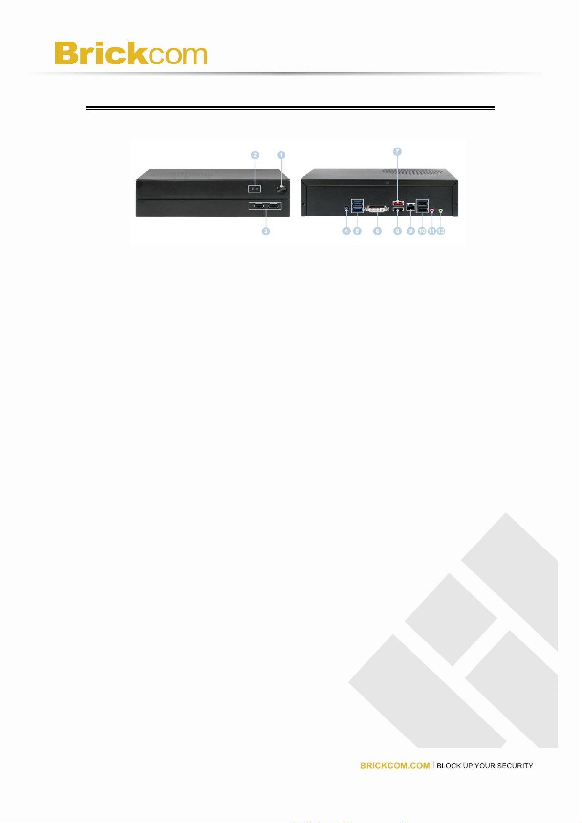
Hardware Description
NR-1104
Figure 1-1. Front & Rear View of NR1104
1. Power button
2. LED indicator: HDD
3. USB 2.0 x2
4. Power connector
5. USB 3.0 x 2
6. DVI-I
7. eSATA x 1
8. HDMI x 1
9. Gigabit LAN
10. USB 2.0 x 2
11. Audio mic input(Reserved)
12. Audio output
5
NR-2104 / NR-2108 / NR-2116
Figure 1-4. Front & Rear View of NR-2104 / NR-2108 / NR-2116
1. Power button
2. LED indicator: HDD
3. USB 2.0 x2
4. Power connector
5. USB 3.0 x 2
6. DVI-I
7. eSATA x 1
8. HDMI x 1
9. Gigabit LAN
10. USB 2.0 x 2
11. Audio mic input(Reserved)
12. Audio output
6

LED Indicators Status
NR-1104
Figure 2-3. NR-1104 Front Panel
Note:
**To turn off your NVR, long pressing power button at least 2 seconds.
**To turn on your NVR, long pressing power button at least 3 seconds.
NR-2104 / NR-2108 / NR-2116
Figure 2-4. NR-2104 / NR-2108 / NR-2116 Front Panel
7
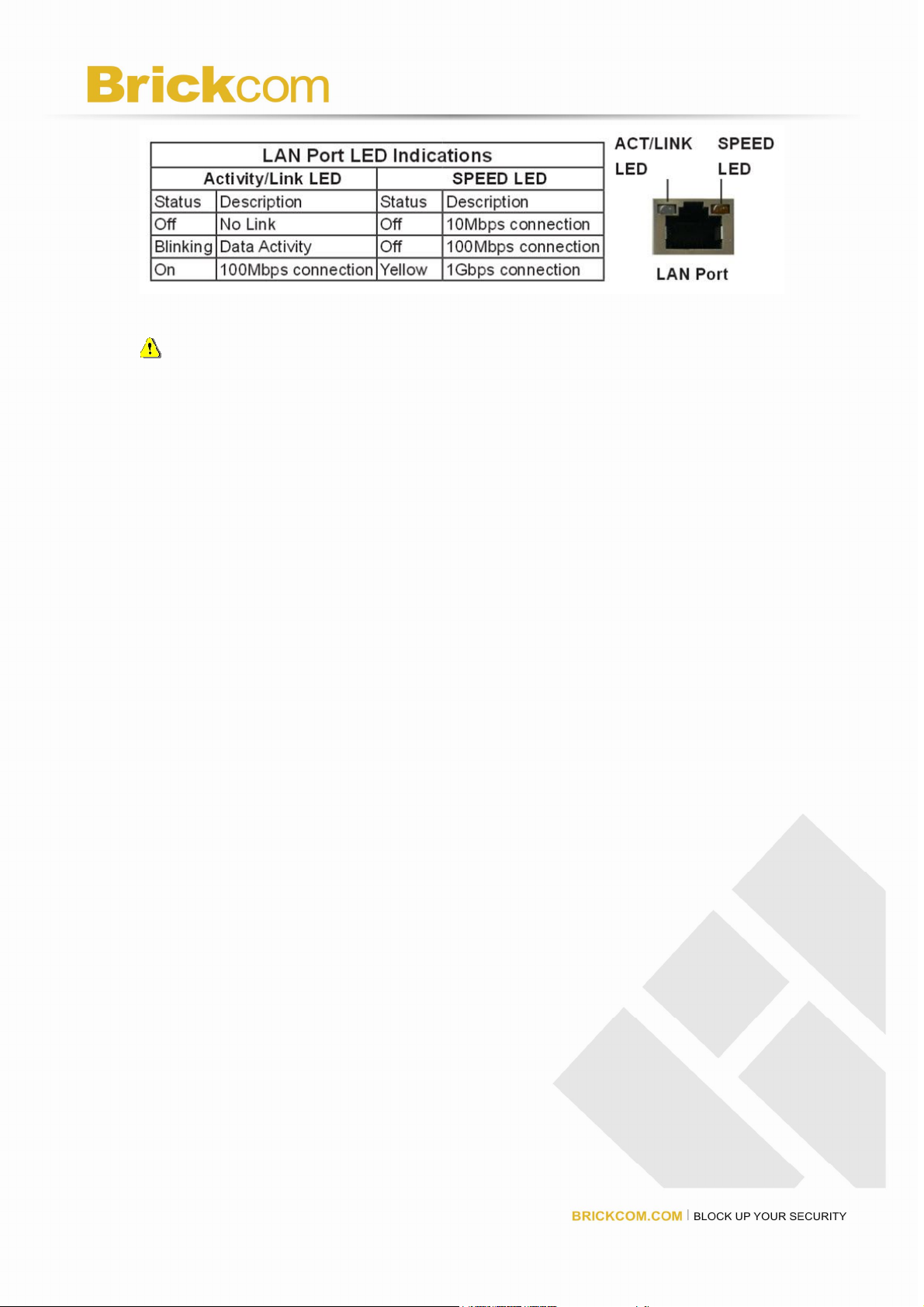
Note:
**To turn off your NVR, long pressing power button at least 2 seconds.
**To turn on your NVR, long pressing power button at least 3 seconds.
8
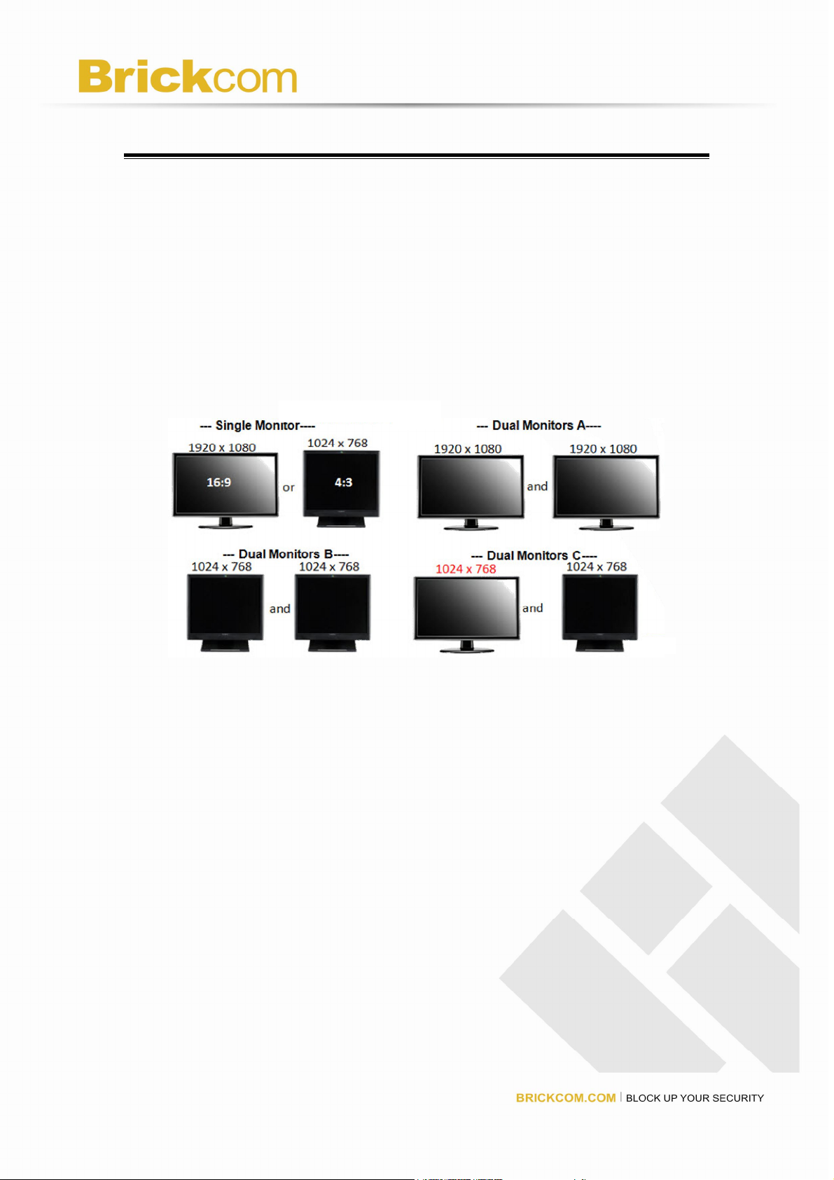
Dual-Monitor Solution: HDMI/VGA/DVI-I Connection
NR-1104/NR-2104/NR-2108/NR-2116 provide HDMI and DVI-I port for local display.
Users can connect both of HDMI and DVI-I at the same time for video output.
Scenario A:If both monitors are Full HD(1920x1080),those will be shown as Full HD.
Scenario B: If both monitors are VGA (1024x768), those will be shown all as VGA.
Scenario C: If one of monitors is 1920x1080 and another is 1024x768, both monitors
are set as 1024x768
9

Chapter 2. NVR Installation
System Requirements
The following information is the minimum level of system requirements for a
personal computer to operate NVR in better performance:
Operating System
Microsoft® Windows® Vista /7 / 8 (32-bit and 64-bit)
Browser
Microsoft® Internet Explorer 8.0 or above (32-bit)
CPU
For channels under 16 : Intel® Dual core CPU 3.0 GHz or above.
For channels over 16 : Intel® i5/i7 CPU 3.3 GHz or above.
Network
Minimum 10/100 Ethernet (Gigabit Ethernet is recommended)
Note: * User is suggested to connect cameras and NVR with Gigabit
switch.
Memory
For channels under 16: DDR3 4G or above.
For channels over 16: DDR3 8G or above
Graphics Adapter
AGP or PCI-Express, minimum 1024×768, 16 bit colors, 1G memory or
above
Note: It is highly recommended to use a graphics adaptor which provides
higher than resolutions 1024 x 768 in order to experience the full
benefits of the software.
Make sure the display DPI setting is set to default at 96DPI
To set DPI value, right-click on desktop, choose “Settings” tab >>
“Advanced” >> “General.”
CD-ROM Drive
It is necessary to read the operating instructions in the provided
CD-ROM.
Adobe Reader
It is necessary to read the operating instructions in the provided CD-ROM.
The audio function will not work if a sound card is not installed in the PC.
Audio may be interrupted depending on network traffic.
10
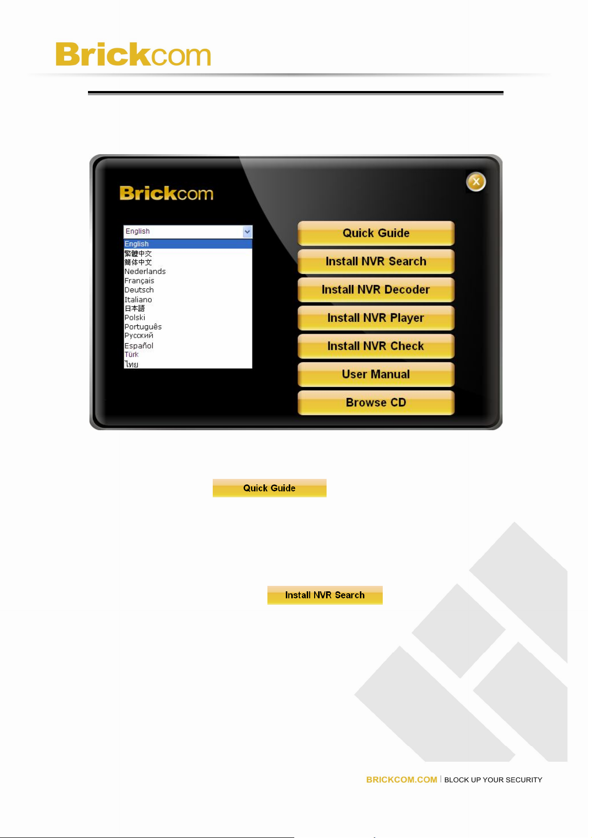
Connect to NVR
To begin, please insert the product CD-ROM in a PC to access the Quick
Guide, User Manual and install the utilities. As user runs the product CD,
the following menu is displayed.
Quick Guide
Click “Quick Guide” to enter the folder and double
click the file to open. Please read Quick Guide to quickly understand the
process of NVR installation.
Install EZ Search
Click “Install NVR Search” to find NVR in the
network. Please follow the instructions to install and NVR Search will run
automatically.
11
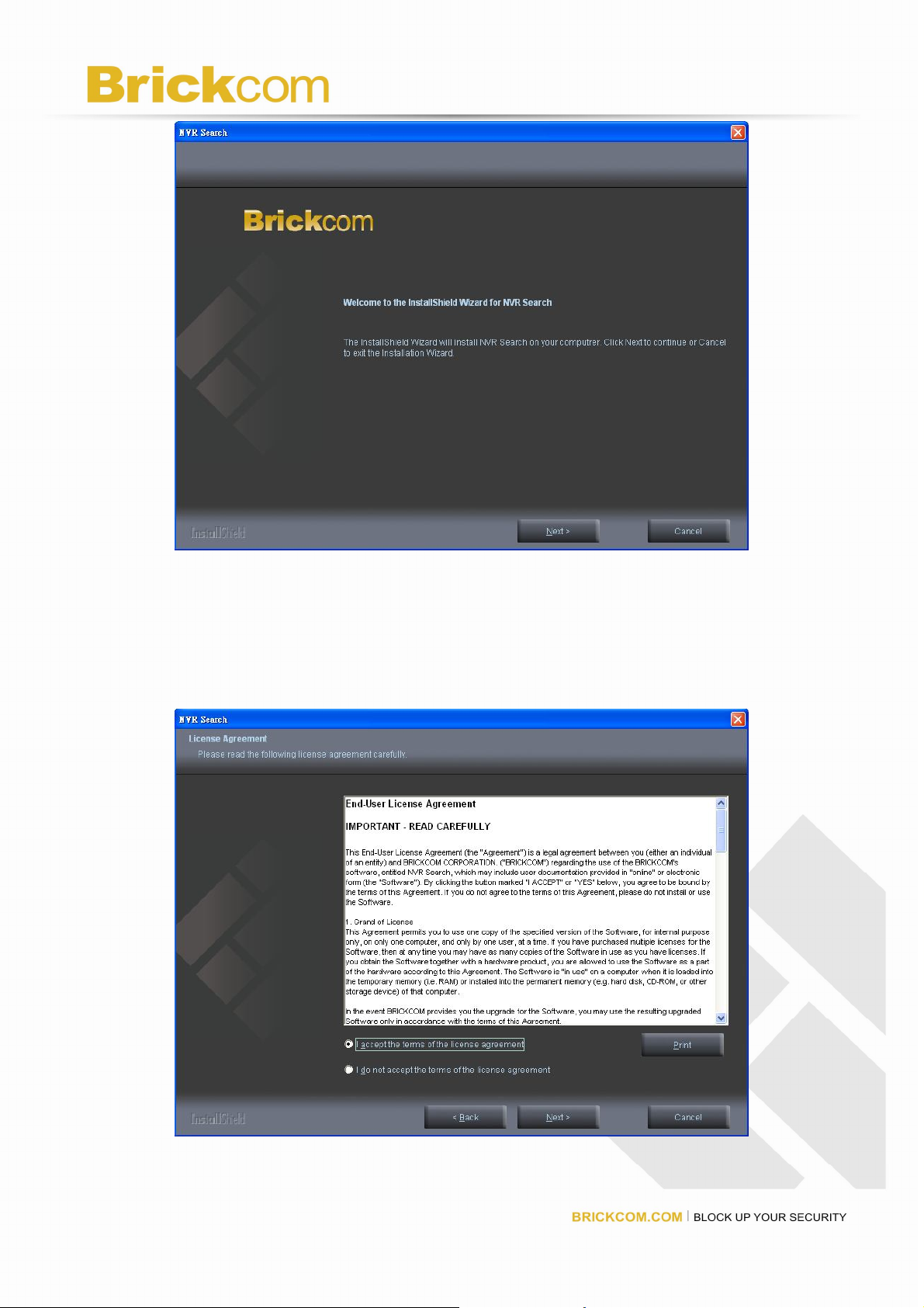
When installing NVR Search, Shield Wizard window for NVR Search will
pop up.
Click “Next” to continue installation.
12

Read the license agreement and click “I accept the terms of the license
agreement”. Click “Next” to continue installation.
Select a location of destination and select a folder where the setup can
install files. The default location is: C:\Program Files\Brickcom\NVR
Search. Users can also install NVR Search in other folder by clicking
“Change” and select a location as below. Click “OK” to save the setting.
13
The window shows that the Install Shield Wizard is installing NVR Search.
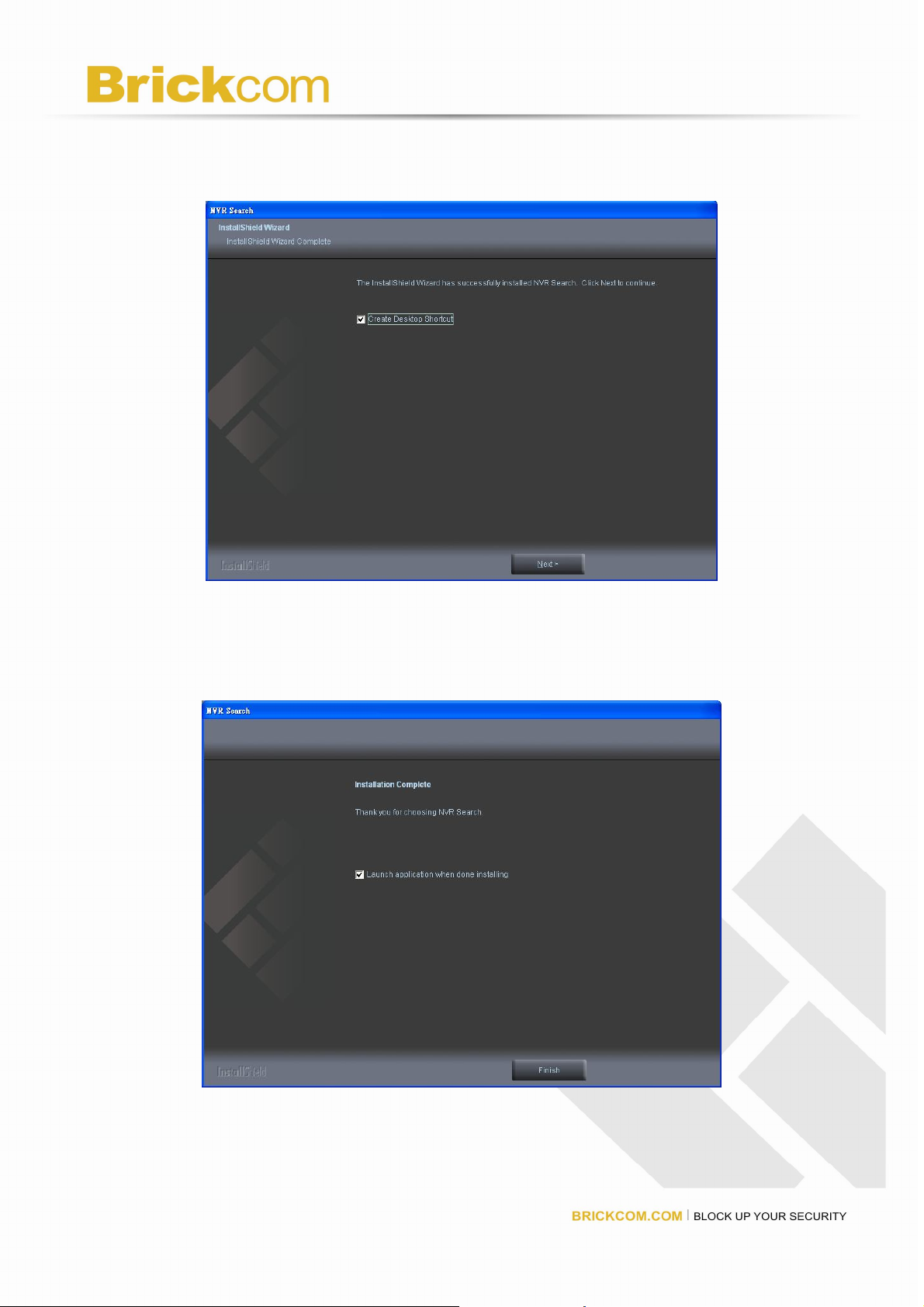
Please wait until the Wizard completes the installation.
The Install Shield has successfully installed NVR Search. Select “Create
Desktop Shortcut” and please click “Next” to continue.
The installation is complete. Please click “Launch application when done
installing” to execute NVR Search.
14
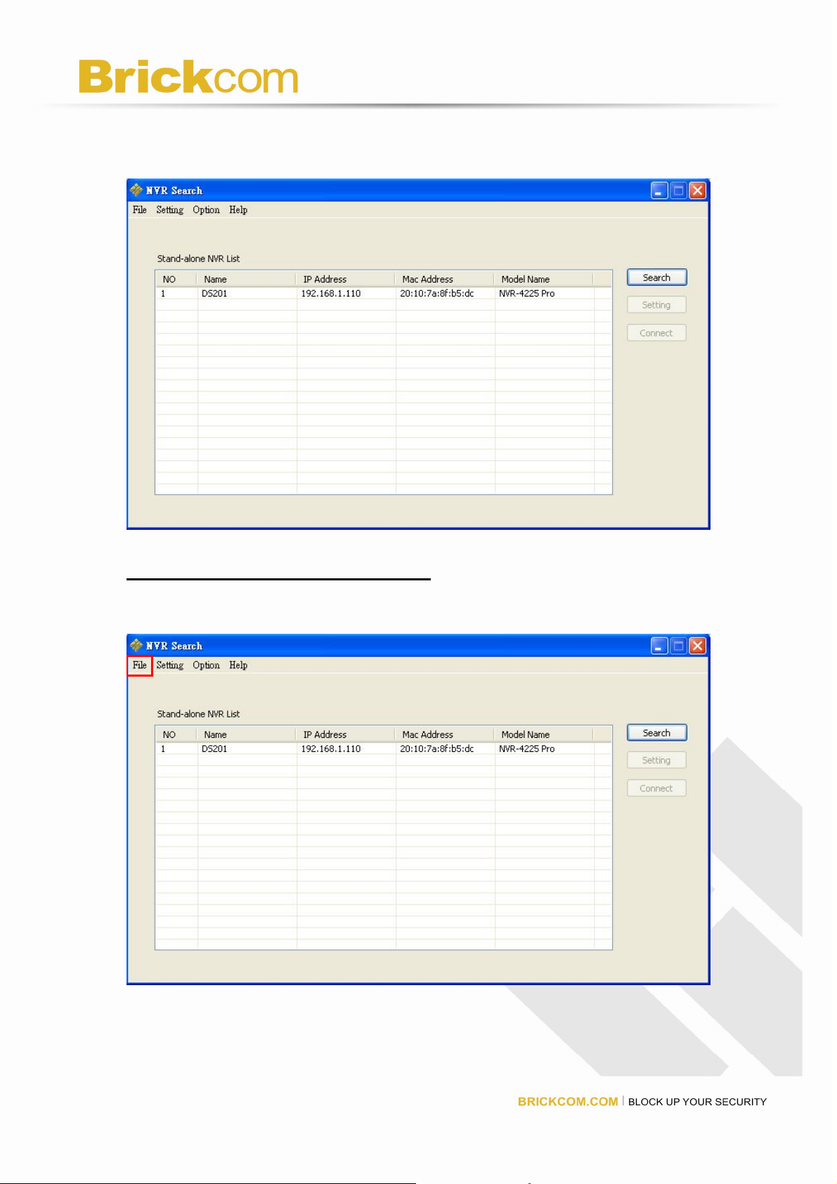
After finishing the setup, the window of NVR Search will pop up.
NVR Search will execute automatically and show NO., Name, IP Address,
Mac Address and Model name of connected Brickcom.
Users can click “Search” to search NVR.
Introduction of NVR Search
NVR Search provides three kinds of toolbars for users:
1. File
You can click “Exit” to leave NVR Search and close the window.
2. Setting
15
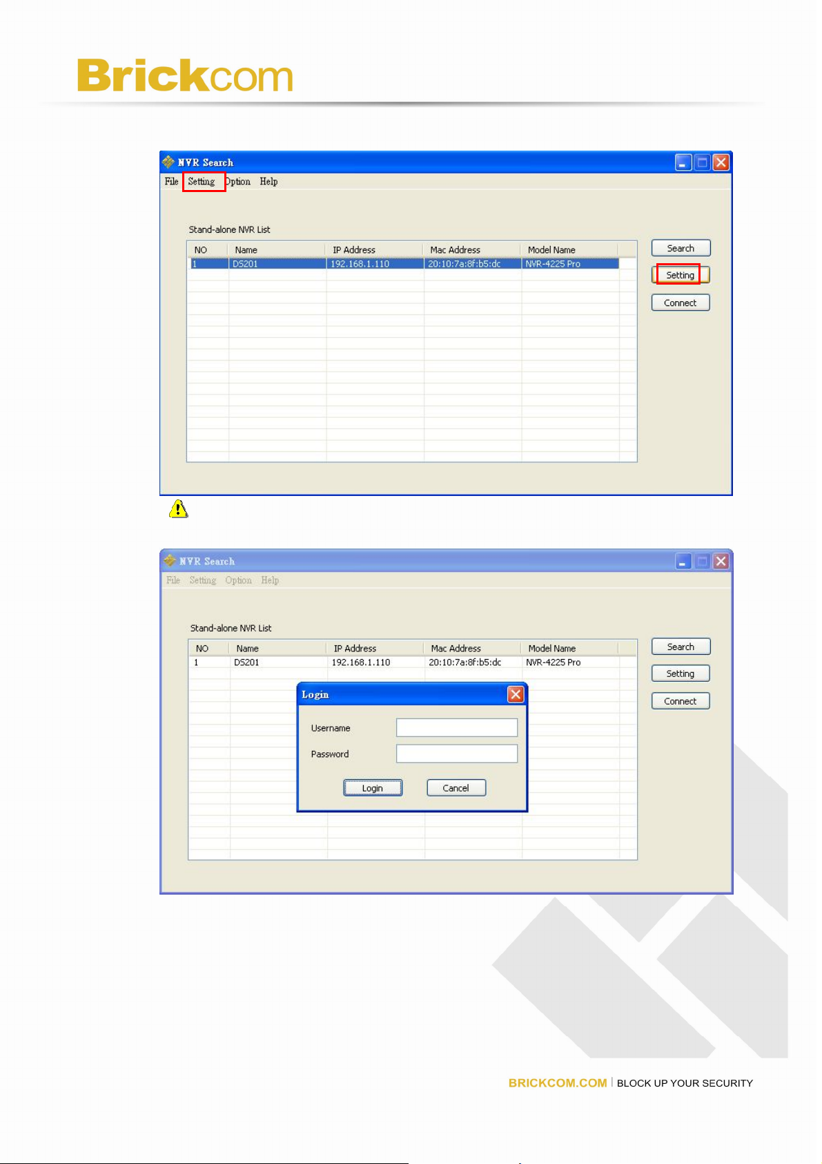
Configure UPnP and Network by clicking “Setting” in the top left or in the middle
right.
Note: Users will be prompted to enter the login information of NVR
before being allowed to change the setting.
When accessing the NVR setting, users will be prompted to enter username
and password. For the first-time use, the default username and password
are admin/admin. When the correct username and password have been
entered, click “Login” to continue.
16
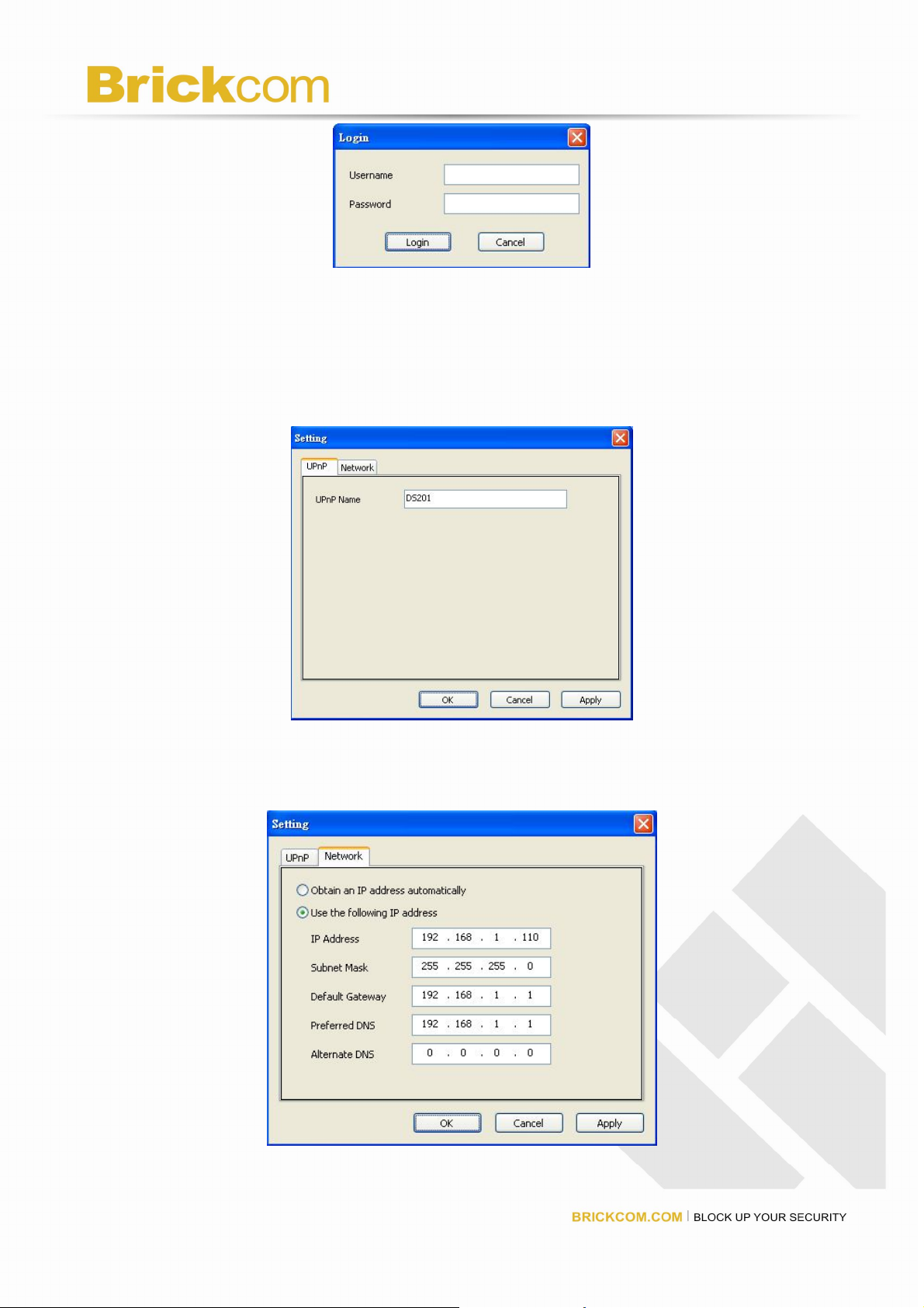
1) UPnP
Universal Plug and Play (UPnP) simplifies the process of adding a
NVR to a local area network. Once connected to a LAN, NVR will
automatically appear on the internet. You can rename UPnP Name on
the NVR. Click “OK” to finish the setting.
2) Network
Two models are provided for setting the network: DHCP and Static IP.
17
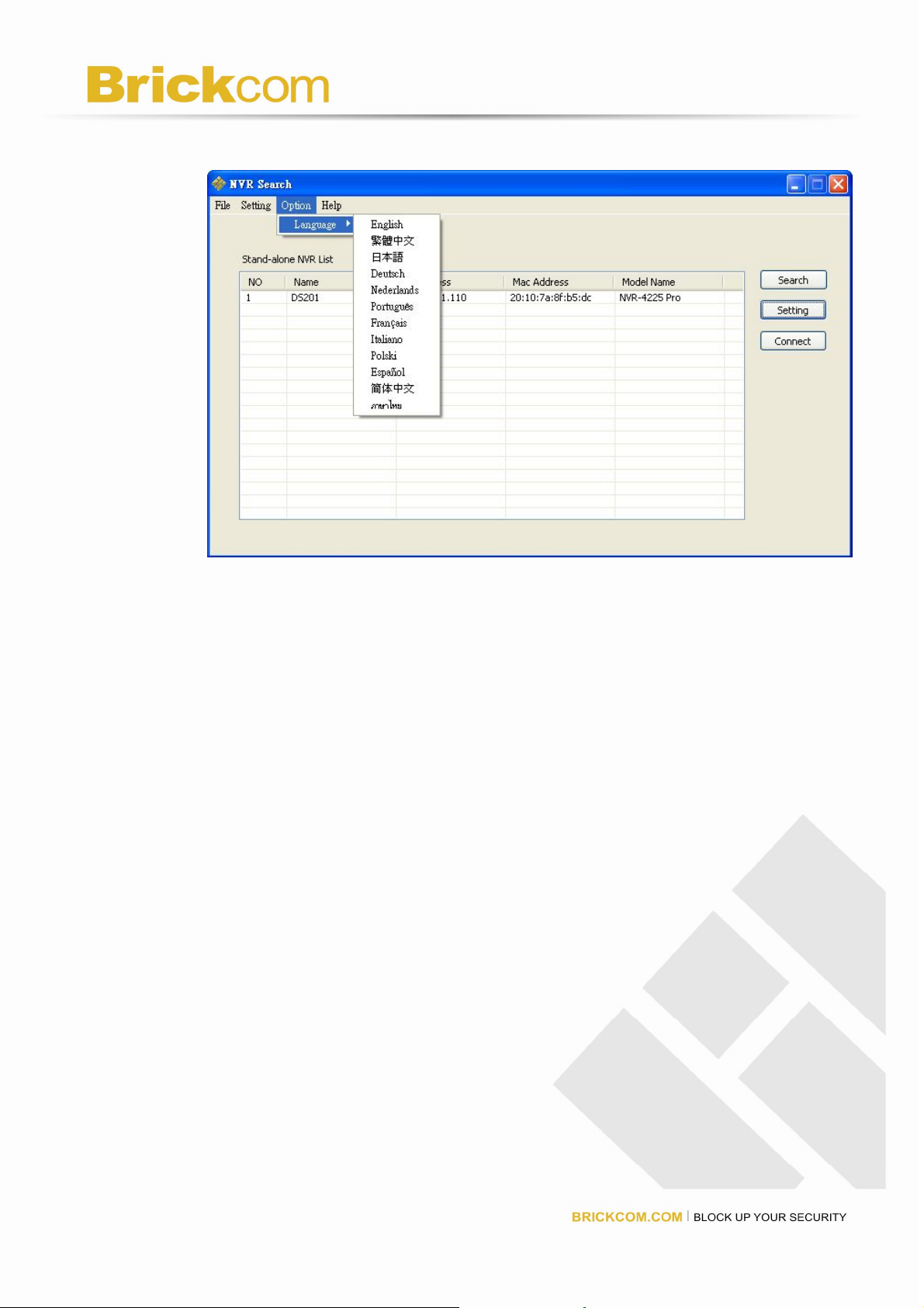
3. Option
Option provides several languages
Once you click “Connect” or double click the selected NVR list, IE browser
will pop up automatically for the web-based interface.
18
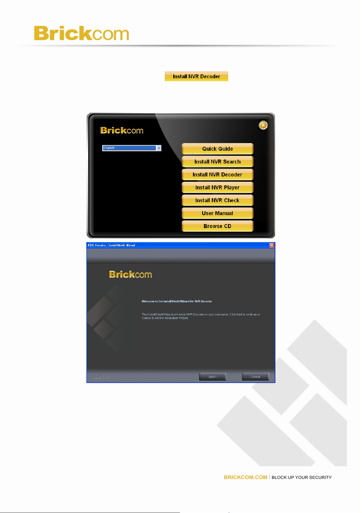
Install NVR Decoder
Click “Install NVR Decoder” to install decoder and
follow the instructions to setup.
Install Shield Wizard window will pop up and please click “Next” to
continue installation.
19
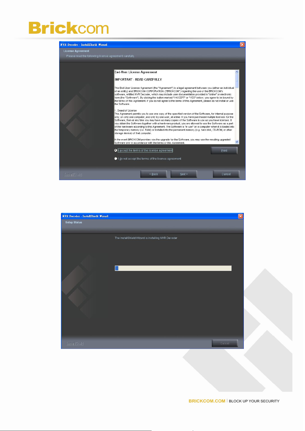
Read license agreement and click “I accept the terms of the license
agreement.” Click “Next” to continue installation.
The installation Wizard is installing NVR Decoder.
20

The installation is complete. Please click “Finish” to close the window.
User Manual
Click “User Manual” to open the folder and double-click on
user manual file to read.
Browse CD
Click “Browse CD” to open the folder of current
Autorun.exe file.
21
Activate Live View
Connect to NVR
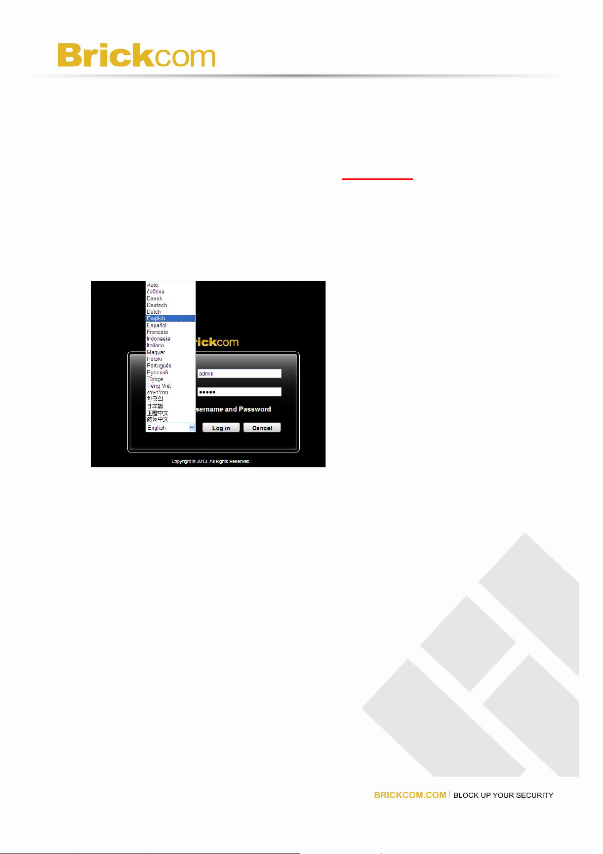
Log in to the system by entering its IP address 192.168.1.245 in IE browser.
Enter username and password:
For first-time use, the default username and password are
“admin/admin.”
Select the languages for the UI.
Allow ActiveX Control
After logging in the NVR, users are recommended to install ActiveX control
for the first-time installation.
Left-click on the description “This website wants to run the following add-on:
‘NVR ActiveX’ from…..”
22
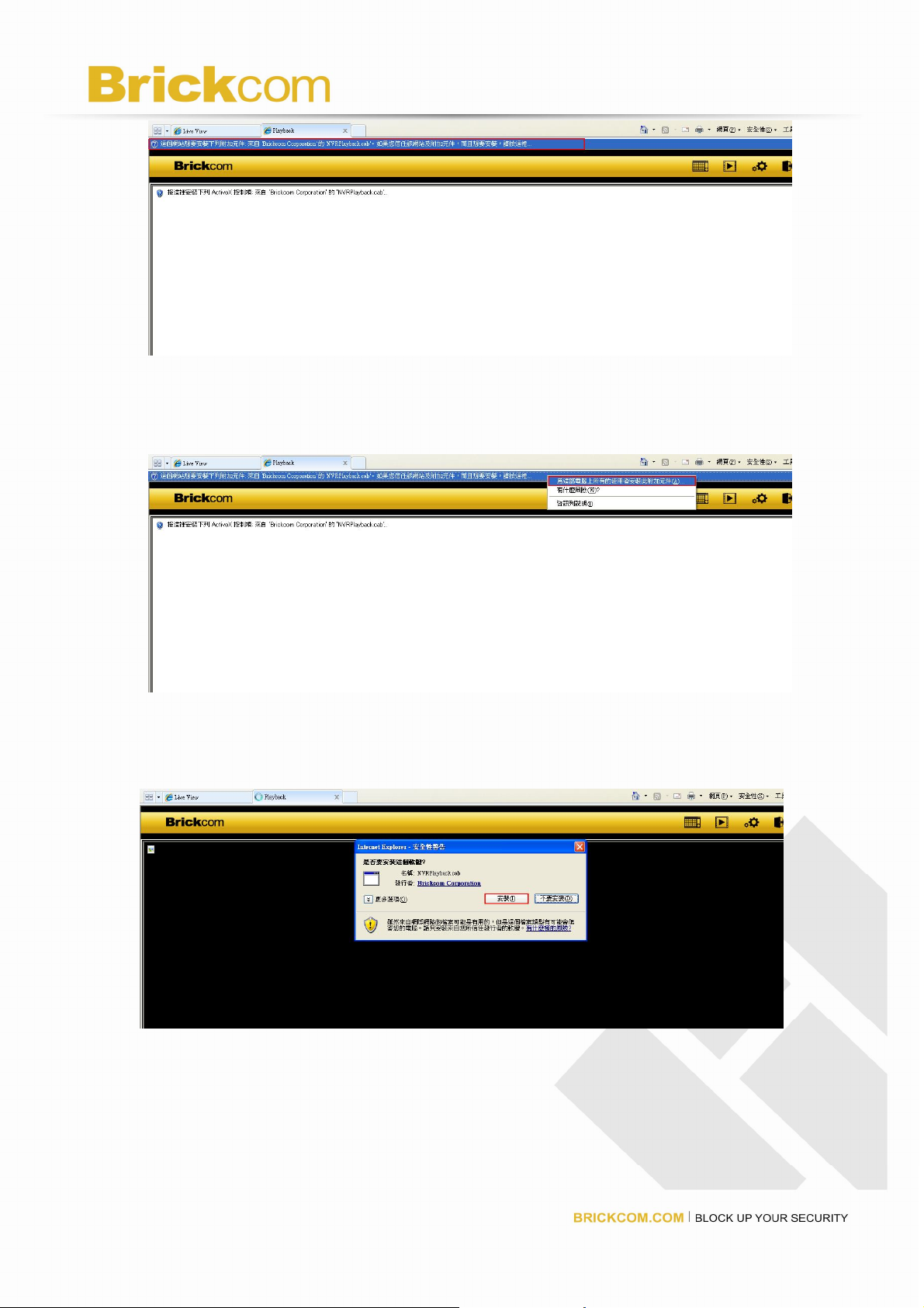
Left-click on the description “Run Add on.”
Left-click “Run” to use licensed ActiveX controls.
23
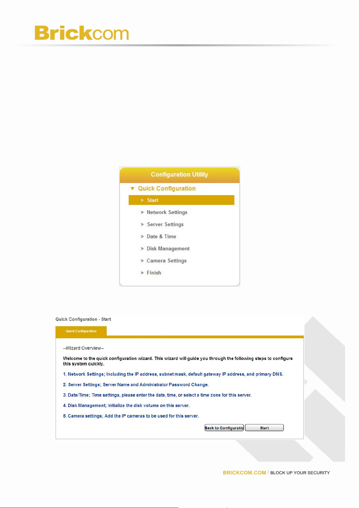
Quick Configuration
After users log in Brickcom and install the ActiveX control, the system will
direct you to set Quick Configuration in five main steps. Follow the
instructions of the Overview of wizard to complete system setup.
Start
System will lead you to “Start” from the drop-down menu of Configuration Utility to
begin.
To initial the configuration, please study the Overview of wizard first. Through five
steps, the wizard will guide you to set up the system quickly.
Click “Start” in Overview of wizard page to begin Quick Configuration.
24
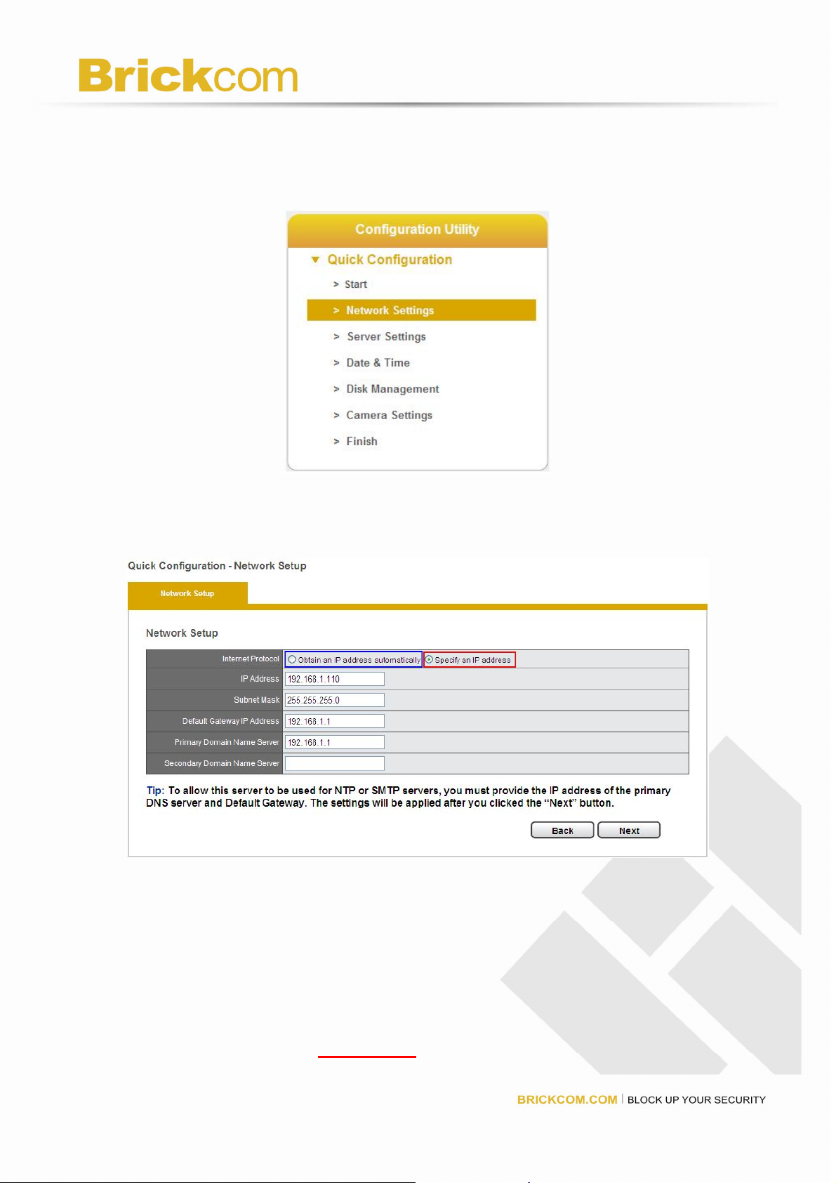
Network Settings
Please select “Network Settings” from the drop-down menu of Configuration Utility
to begin.
Users need to adjust the settings in the Network Setup page in order to let
NVR work properly within network.
There are 2 methods to configure IP address
1. Obtain an IP address automatically (NVR Default)
Obtain an available dynamic IP address assigned by a DHCP server. If this
option is selected, NVR will automatically obtain an available dynamic IP
address from the DHCP server once it connects to the network.
2. Specify an IP address.
If there is no DHCP server existing in network environments, the static IP
address will be given as192.168.1.245. It should be adaptable in most
25
networking environment, and user can choose to maintain the default IP
address or change it in this page. However, it’s recommended setting different
IP address of NVR if there is more than one NVR in the same LAN.
To assign a static IP address to the NVR:
1. Select “Specify an IP address”
2. Enter the IP address, Subnet Mask, Default Gateway IP Address and DNS
server address.
3. If IP Address is changed, user needs to log out NVR and login in again.
Click “Next” to proceed with the configuration.
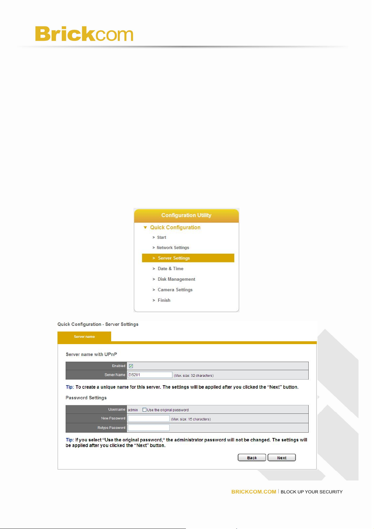
Server Settings
Please select “Server Settings” from the drop-down menu of Configuration Utility to
begin.
26
Server name with UPnP
Universal Plug and Play (UPnP) simplifies the process of adding a NVR to a local area
network. Once connected to LAN, the NVR will automatically appear on the internet.
User can select to enable the function with UPnP and edit a sever name.
Password Settings
Each NVR comes with a built-in “admin” account with password “admin.”
It’s highly recommended to change the password upon the initial login.
Enter a new password in the “New Password” field and enter it again in
“Retype Password.”Since you confirm “Next,” the administrator
password will be changed.
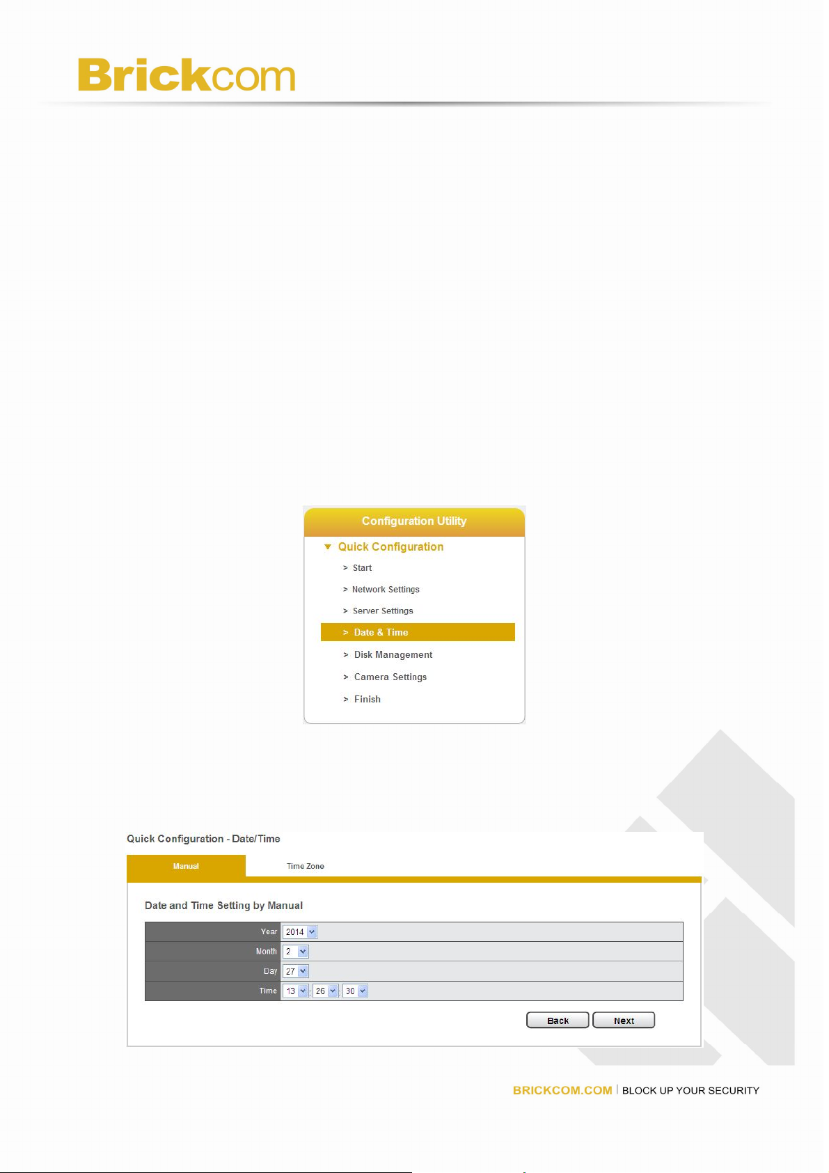
Date &Time
Please select “Date & Time” from the drop-down menu of Configuration Utility to
begin.
1. Manual setting
Use the drop-down list and configure the time manually. Select the Year, Month,
Date and Time. Time setting will be effective when you click “Next.”
27

2. Time Zone: Synchronize with an Internet time server automatically.
Select the time zone of your area and update the date and time of the Brickcom
automatically with an NTP server. User also has an option to automatically adjust
daylight saving time.
Configure the time and date by verifying and adjusting current local time and
daylight saving to avoid the following errors:
Incorrect display time for playback videos.
Inconsistent display time of event logs and when they actually occur.
Please enter the hostname of a valid NTP server to synchronize the server time with
an Internet time server. NTP (Network Time Protocol) is a protocol to synchronize
the clocks of a computer system.
28
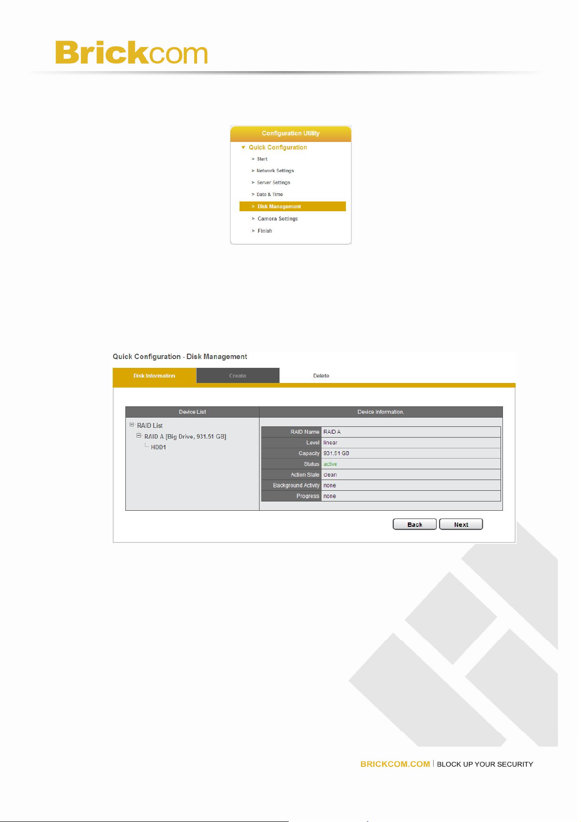
Disk Management
Please select “Disk Management” from the drop-down menu of Configuration
Utility to begin.
If hard disk is not installed in NVR, the page will show “Disk doesn’t exist.”
Once an available hard disk drive is inserted into the tray, Disk Information will show
in Device Information and users can start to create new RAID Disk.
1. Disk Information
Device Information provides details of the hard disk drive: HDD Model,
Serial NO., Capacity and Status.
29
 Loading...