

Page 1
Hardware User’s Manual
Megapixel Day & Night
Bullet Network Camera
OB-E200Af / OB-E200Nf
Product name:
Network Camera (OB-E200Af / OB-E200Nf)
Release Date:
2014/9
Version:
V1.0
Web site:
www.brickcom.com
Email:
© 2014 Brickcom Corporation. All Rights Reserved
Editor:
Tracy Cho
Page 2

Table of Contents
Before You Use This Product ....................................................................................... 1
FCC Warning .................................................................................................................. 2
Regulatory Information ................................................................................................. 3
Chapter 1 - Package Contents ...................................................................................... 4
Chapter 2 - Megapixel Day & Night Bullet Network Camera Overview ..................... 5
Chapter 3 - Device Appearance Description ............................................................... 6
Chapter 4 - LED Behavior ............................................................................................. 7
Chapter 5 - Hardware Reset .......................................................................................... 8
Chapter 6 - System Requirements ............................................................................... 9
Chapter 7 - Installation ................................................................................................ 10
7.1 Hardware Installation ..................................................................................... 10
7.2 Camera Connection ........................................................................................ 10
7.3 Software Installation ....................................................................................... 12
7.4 Launch EasyConfig ........................................................................................ 15
Chapter 8 - Accessing the Network Camera.............................................................. 24
8.1 Check Network Settings ................................................................................ 24
8.2 Add the Password to Prevent Unauthorized Access ................................... 24
8.3 Viewing Video Streams with Internet Explorer............................................. 25
Chapter 9 - Viewing Video Streams with BRC64 ....................................................... 26
Page 3

Before You Use This Product
In many countries, there are laws prohibiting or restricting the use of surveillance
devices. This Network Camera is a high-performance, web-ready camera which can be
part of a flexible surveillance system. It is the user’s responsibility to ensure that the
operation of this camera is legal before installing this unit for its intended use.
Upon opening the product’s package, verify that all the accessories listed on the
“Package Contents” are included. Before installing the Network Camera, read the
warnings in the “Quick Installation Guide” to avoid misuse. When installing the Network
Camera, carefully read and follow the instructions in the “Installation” chapters to avoid
damages due to faulty assembly or installation.
1
Page 4

FCC Warning
This device complies with Part 15 of FCC rules.
Operation is subject to the following two conditions:
(1) This device may not cause harmful interference.
(2) This device must accept any interference received, including interference that may
cause undesired operations.
2
Page 5
Regulatory Information
Federal Communication Commission Interference Statement
This equipment has been tested and found to comply with the limits for a Class B digital
device, pursuant to Part 15 of the FCC Rules. These limits are designed to provide
reasonable protection against harmful interference in a residential installation. This
equipment generates uses and can radiate radio frequency energy and, if not installed
and used in accordance with the instructions, may cause harmful interference to radio
communications. However, there is no guarantee that interference will not occur in a
particular installation. If this equipment does cause harmful interference to radio or
television reception, which can be determined by turning the equipment off and on, the
user is encouraged to try to correct the interference by one of the following measures:
- Reorient or relocate the receiving antenna.
- Increase the separation between the equipment and receiver.
- Connect the equipment into an outlet on a circuit different from that to which the
receiver is connected.
- Consult the dealer or an experienced radio/TV technician for help.
FCC Caution: Any changes or modifications not expressly approved by the party
responsible for compliance could void the user's authority to operate this equipment.
This device complies with Part 15 of the FCC Rules. Operation is subject to the following
two conditions: (1) This device may not cause harmful interference, and (2) this device
must accept any interference received, including interference that may cause undesired
operation.
IMPORTANT NOTE:
FCC Radiation Exposure Statement:
This equipment complies with FCC radiation exposure limits set forth for an
uncontrolled environment. This equipment should be installed and operated with
minimum distance 20cm between the radiator & your body.
This transmitter must not be co-located or operating in conjunction with any other
antenna or transmitter.
The availability of some specific channels and/or operational frequency bands are
country dependent and are firmware programmed at the factory to match the
intended destination. The firmware setting is not accessible by the end user.
3
Page 6
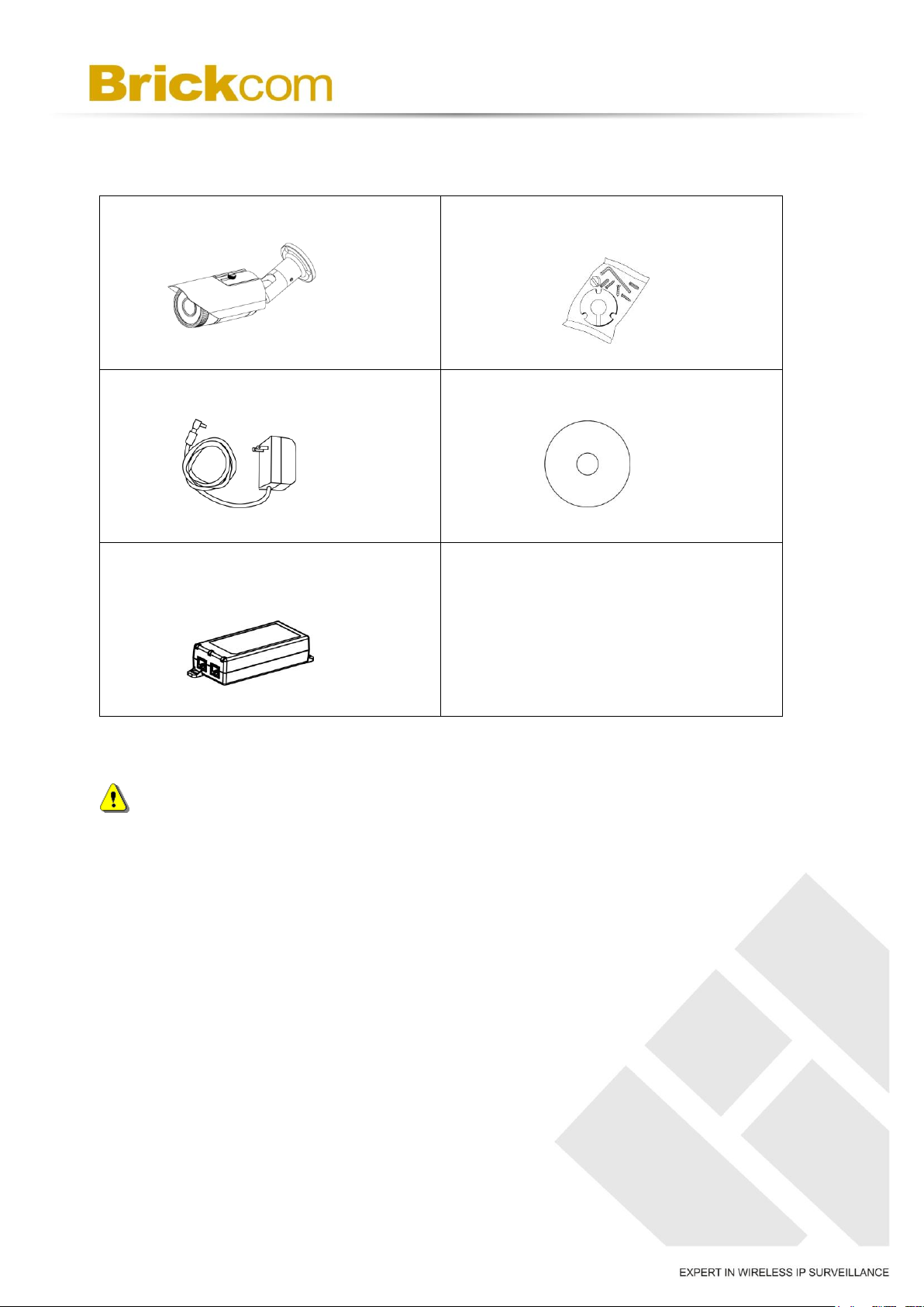
1. Network Camera
2. Screw Bag
3. Power Adapter(*)
4. Product CD
5. POE Injector(*)
Chapter 1 - Package Contents
NOTE - (*) These are optional features.
4
Page 7
Chapter 2 - Megapixel Day & Night Bullet
Network Camera Overview
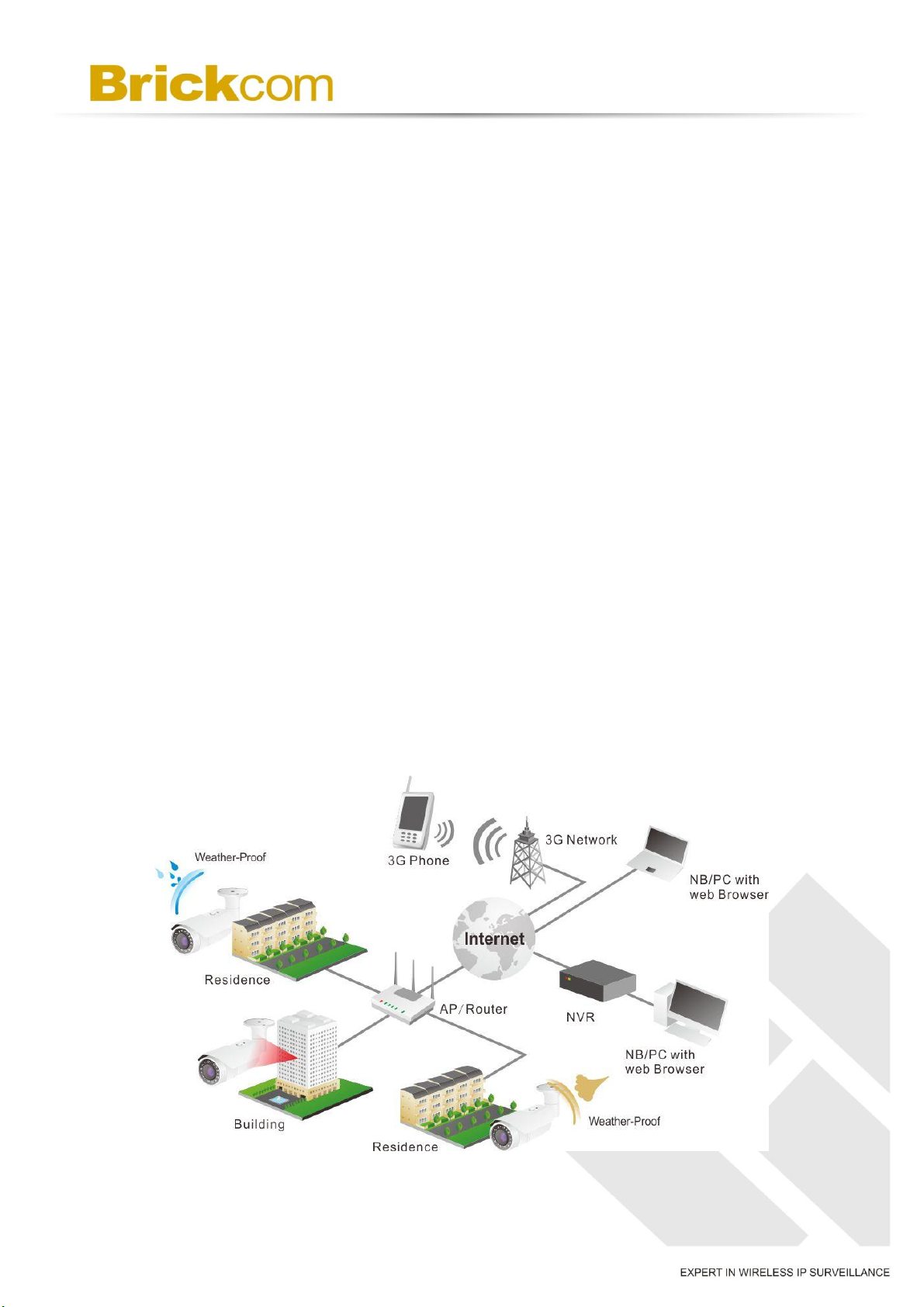
The Brickcom OB-E200Af / OB-E200Nf outdoor bullet network camera adopts the
two-megapixel sensor which allows the camera to deliver extremely clear and detailed
images that CCTV cameras cannot offer. To optimize use of the megapixel resolution,
the OB-E200Af / OB-E200Nf use efficient H.264/ MJPEG codec compression to deliver
dual configurable video streams simultaneously. These features make OB-E200Af /
OB-E200Nf the perfect outdoor camera for neighborhood, school campus, and parking
lot surveillance.
The OB-E200Af / OB-E200Nf supports Power over Ethernet and enables the camera to
use the same cable for power and data transmission, eliminating the need to install an
external power supply. With an IP66 certified outdoor enclosure, the OB-E200Af /
OB-E200Nf is not only weather proof, but also dust and rust resistant.
The OB-E200Af / OB-E200Nf supports the removable IR cut filter, the camera can
automatically switch into the day mode or night mode, which allows the users to enjoy
the best quality of images in the different circumstances. The megapixel day and night
bullet network camera is the best choice for the outdoor application.
5
Page 8
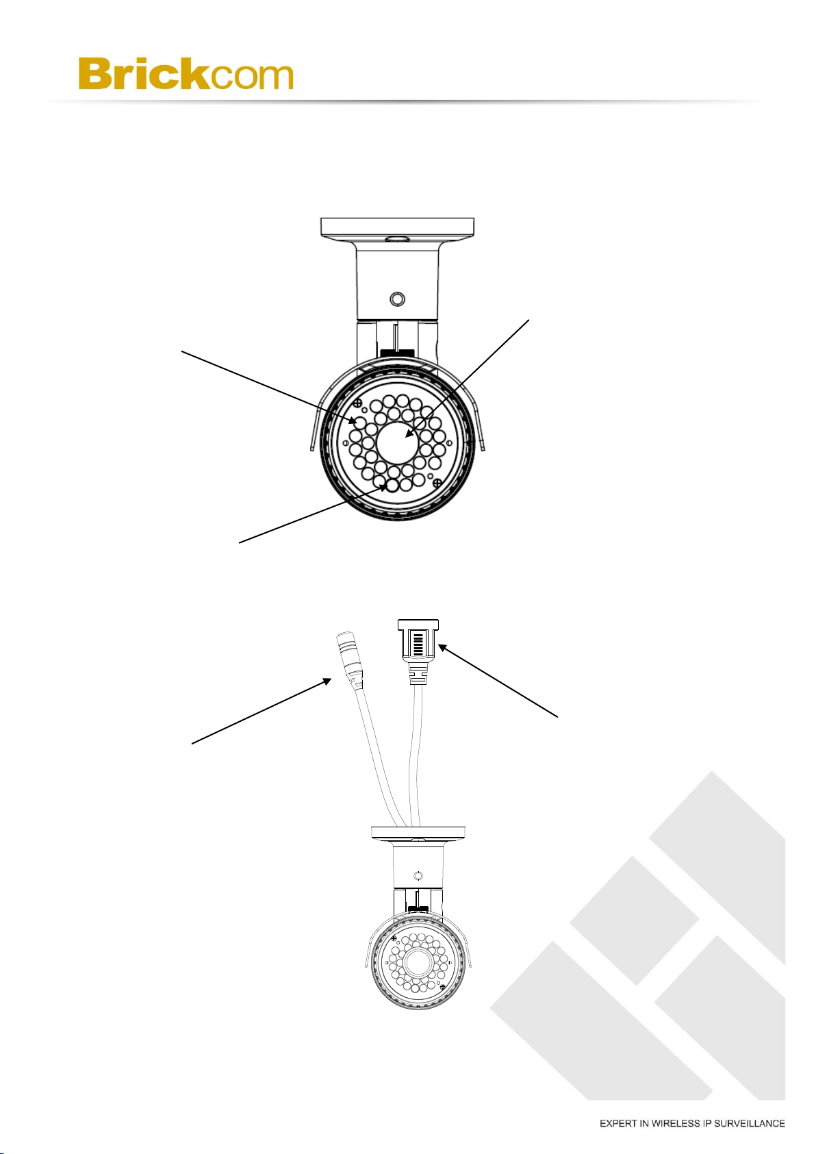
Lens
IR Leds
Light Sensor
RJ45 Ethernet Port
DC12V Power Input
Chapter 3 - Device Appearance Description
6
Page 9

Function
LED Behavior
Description
Ethernet Link
Continuous illumination (Green)
Ethernet Connected
Data Link
Blinking (Orange)
Data Transmitting
Chapter 4 - LED Behavior
7
Page 10
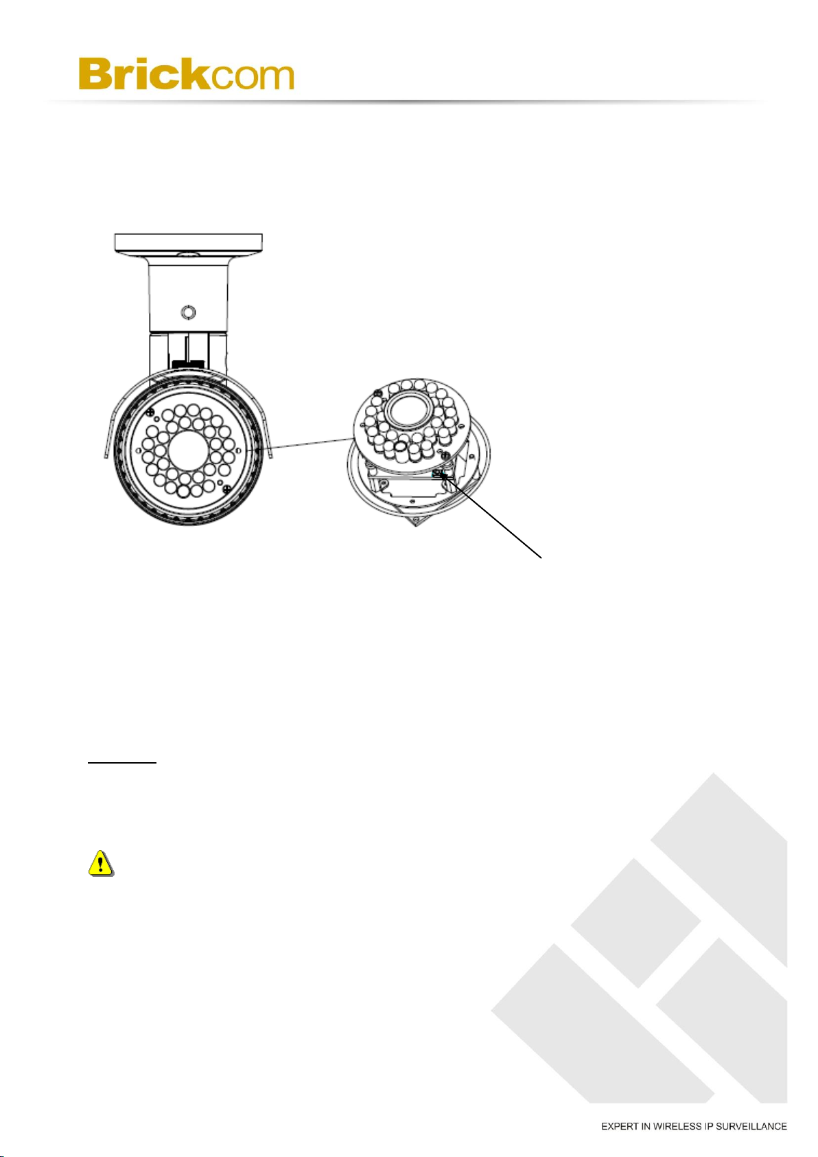
Reset Button
Chapter 5 - Hardware Reset
The Reset Button can be used to restore the camera to factory default settings. If the
camera experiences a problem, rebooting the camera may correct the problem. If the
problem remains, please restore the camera to factory default settings and reinstall the
software.
To Reset
Press and hold the Reset Button for more than 10 seconds using a paper clip or thin
object. Wait for the camera to reset to default.
NOTE - By resetting the camera, all settings will be restored to the factory default
settings.
8
Page 11

Chapter 6 - System Requirements
Operating System: Microsoft Windows 7, Vista, XP, 2000
CPU: Pentium 3GHz or faster
Network Interface: 10/100Mbps Network interface card must be installed
Web Browser: Microsoft Internet Explorer 6/7 or above, Firefox, Google Chrome,
Safari
9
Page 12
Chapter 7 - Installation
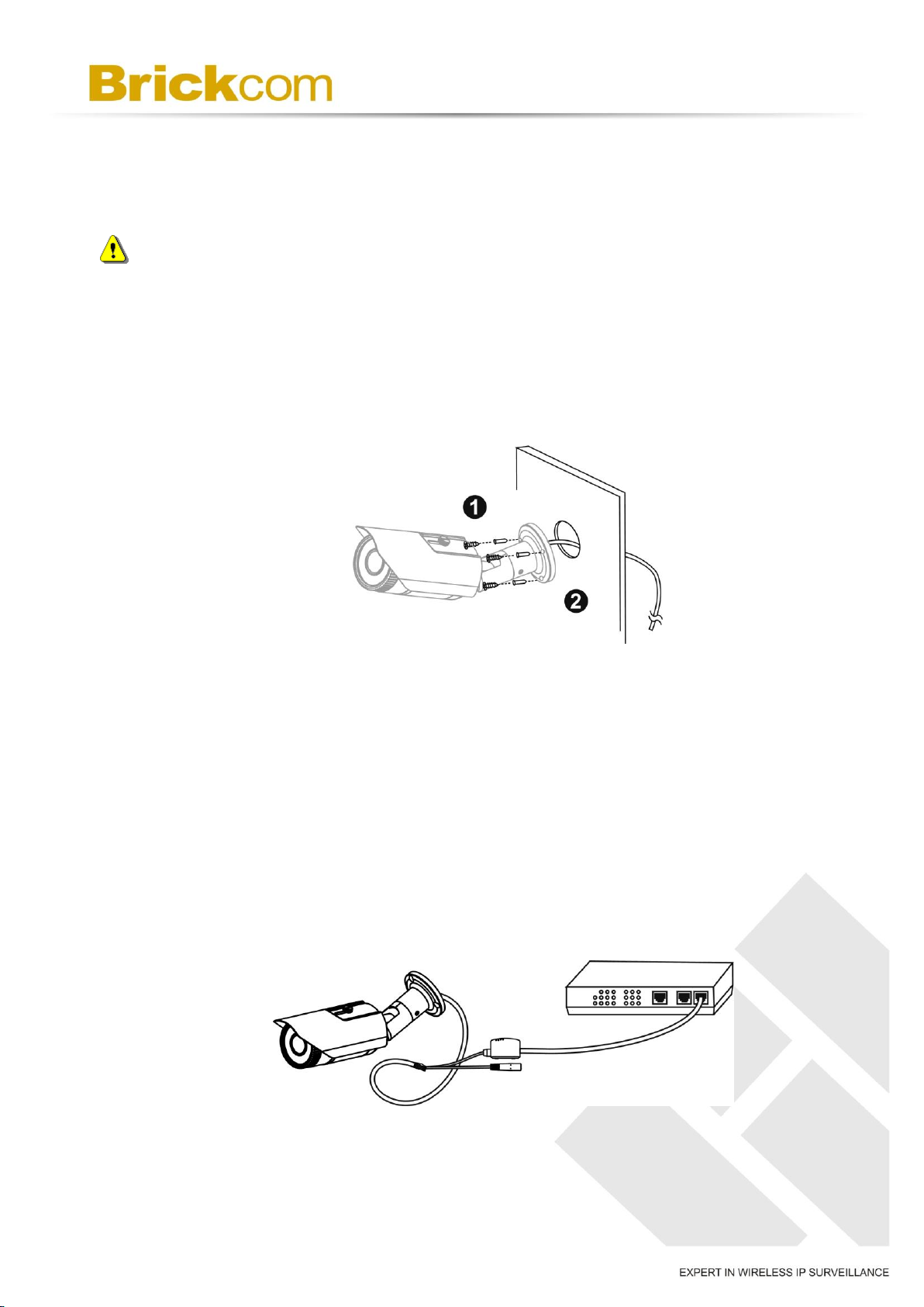
7.1 Hardware Installation
WARNING - Do not mount the camera on a soft material. The camera may fall
and be damaged.
A. Wall Installation
(1) Drill three holes into the wall. (2) Hammer the supplied plastic anchors into the three
holes. (3) Use a screwdriver and the supplied screws to secure the camera to the wall.
7.2 Camera Connection
The Bullet Series is DC12V and PoE compliant, so there are two options for connecting
the camera to a power and Ethernet source. The camera can either be connected to a
PoE-enabled switch or a non-PoE switch.
a. If using a PoE-enabled switch:
Use a single Ethernet cable to connect the camera to the PoE-enabled switch.
10
Page 13
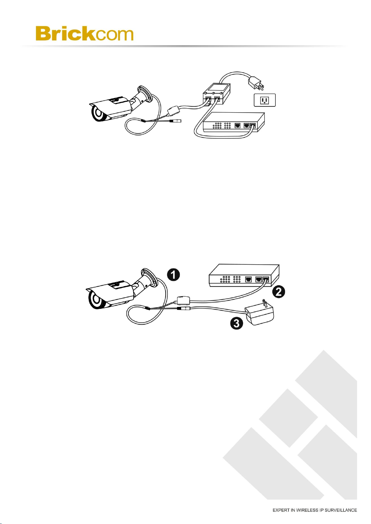
b. If using a non-PoE switch:
1. Use a standard RJ-45 cable to connect the camera to a PoE Injector.
2. Use a standard RJ-45 cable to connect the PoE Injector to the non-PoE switch.
3. Use a standard power cable to connect the PoE Injector to a power outlet.
c. If using the DC12V for the power supply. The RJ45 cable will be data
transmission.
11
Page 14
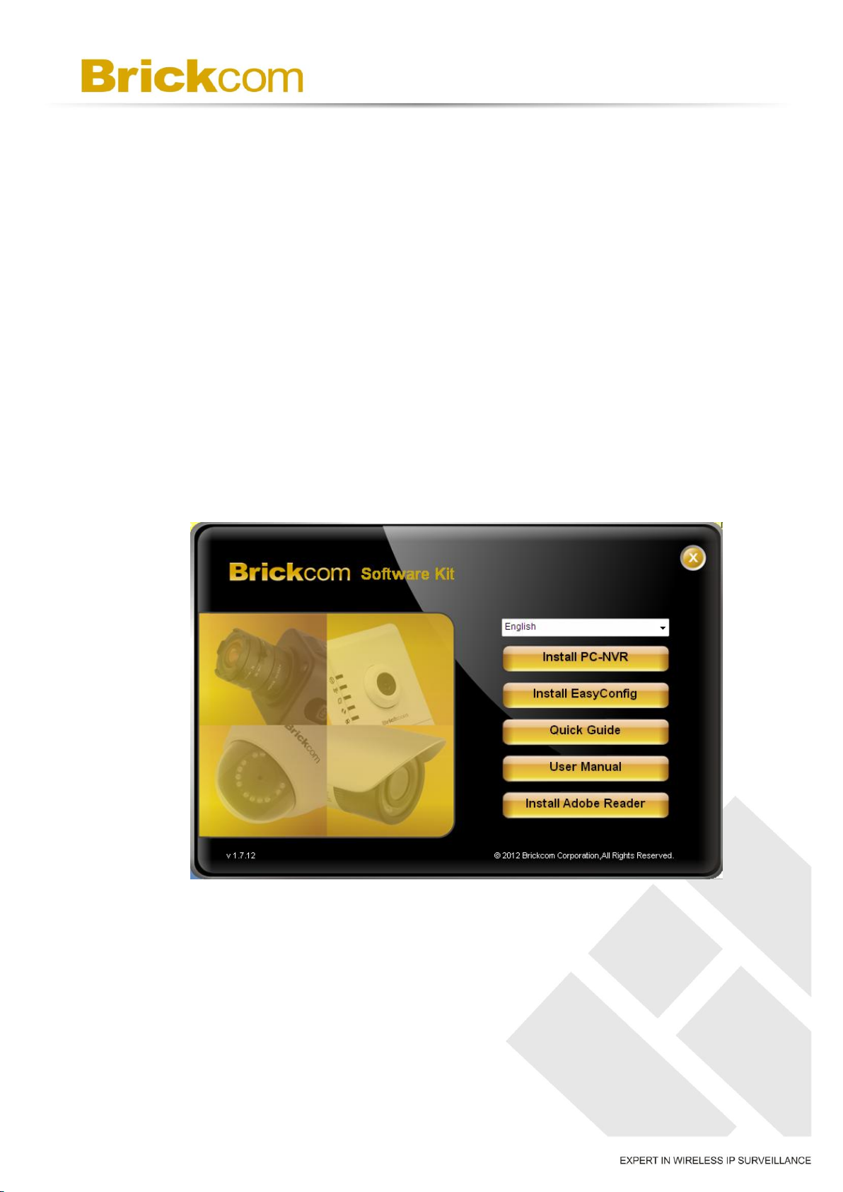
7.3 Software Installation
In this manual, "User" refers to whoever has access to the Network Camera, and
"Administrator" refers to the person who can configure the camera and grant user
access to the camera.
After checking the hardware connection, run the Installation Wizard program included on
the product’s CDROM to automatically search the intranet for the camera. There may be
many cameras on the local network. Differentiate the cameras using the serial number
which is printed on the labels on the carton and the bottom of the camera.
A. Insert the Installation CD into the CD-ROM driver. Run Auto-Run Tool directly from
the CD-ROM to start the installation. When installing the Brickcom software kit for
the first time, select a desired language for the interface. The available languages
are listed in the scroll box. Click <Install> and follow the steps to install the
EasyConfig wizard on the desired computer.
12
Page 15
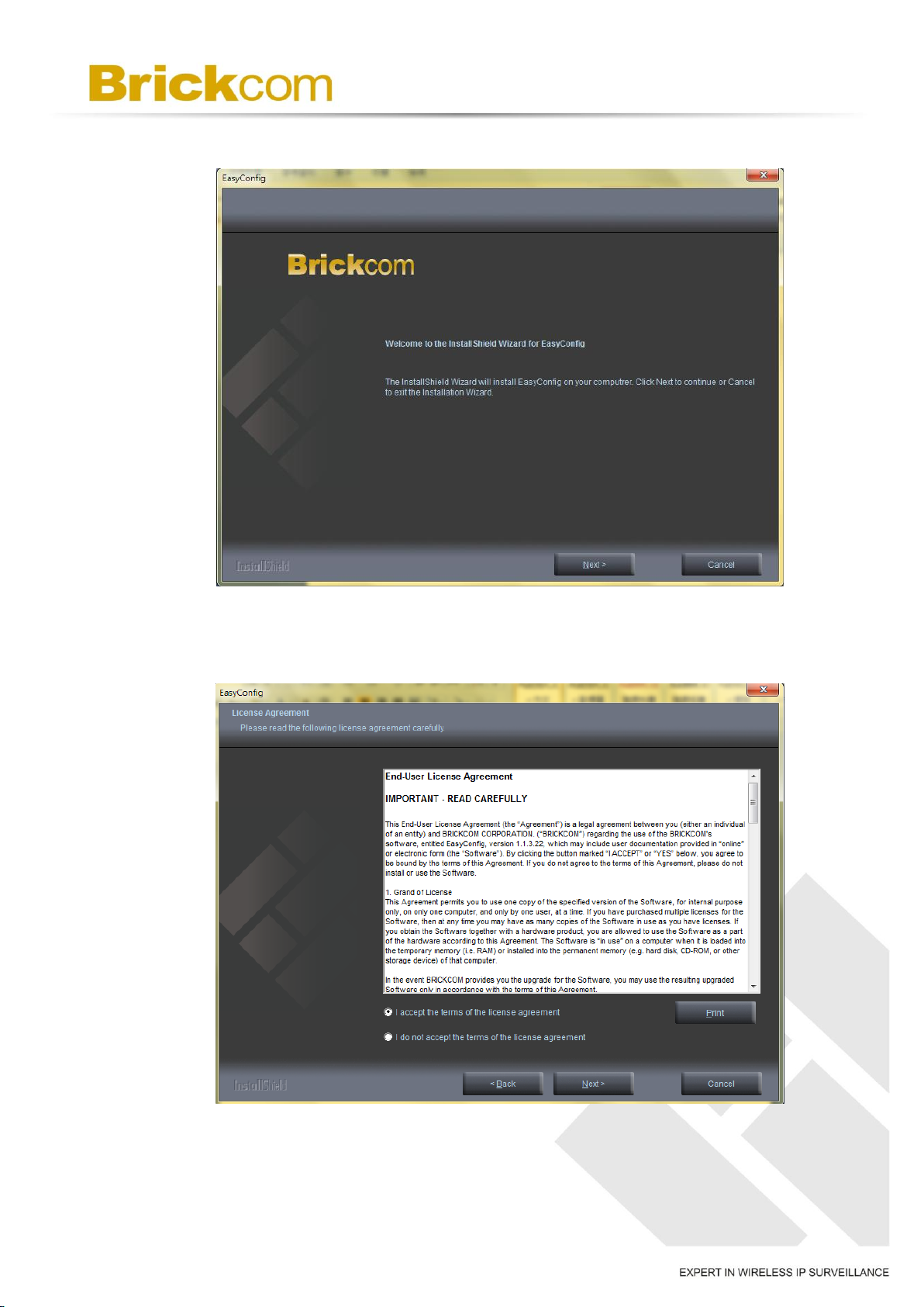
B. In the Install Shield Wizard dialog box, click <Next> to continue.
C. Read the End-User License Agreement and check the option “I accept the terms of
the license agreement”. Click <Next> to continue.
13
Page 16
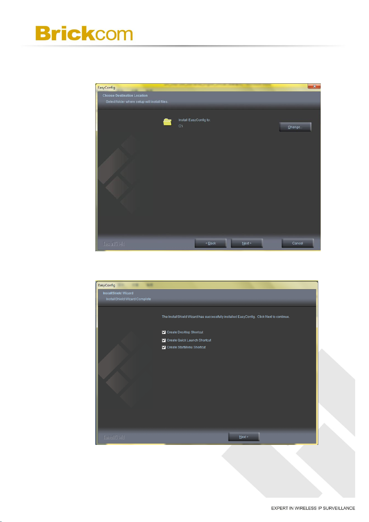
D. Click <Change> to change the appointed folder where installation and program files
will be stored. Click <Next> to continue.
E. Select to create shortcuts. Click <Next> to continue.
14
Page 17
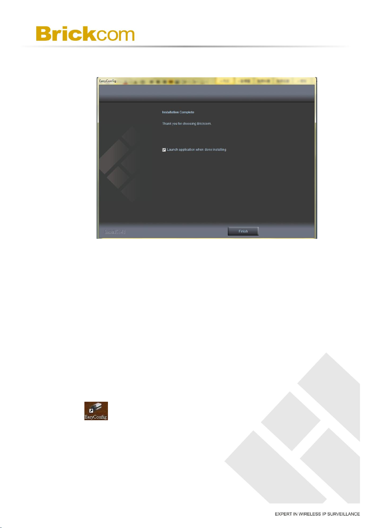
F. Select the application and click <Finish>. When launching the PC-NVR program,
please refer to the PC-NVR user manual.
7.4 Launch EasyConfig
Users can search cameras by EasyConfig and configure the settings below:
IP address configuration
Easylink configuration
Live View & Individual Camera Modification
To launch EasyConfig, select “EasyConfig” from the start menu. If Complete Setup type
was used in the software installation, an EasyConfig icon was installed on the desktop.
Double click to launch EasyConfig.
If Custom Setup type was used in the software installation but an EasyConfig icon was
not installed on the desktop, by default the program is installed under “C:\Program
15
Page 18
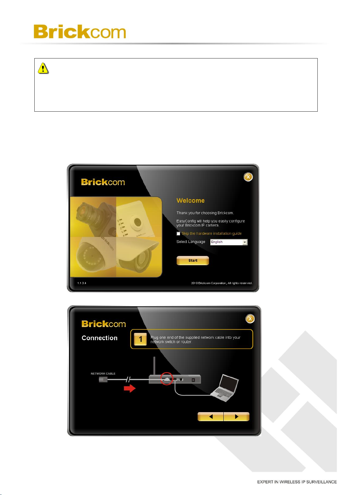
NOTE - Check <Skip the hardware installation guide> to skip checking the
hardware connection. To check the hardware installation settings, do not check the option
box.
Files\Brickcom\EasyConfig”.
1. Click <Start> to continue. The program will automatically search for the camera in
the intranet.
16
Page 19
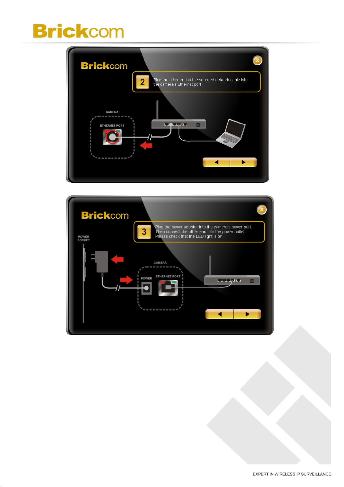
17
Page 20
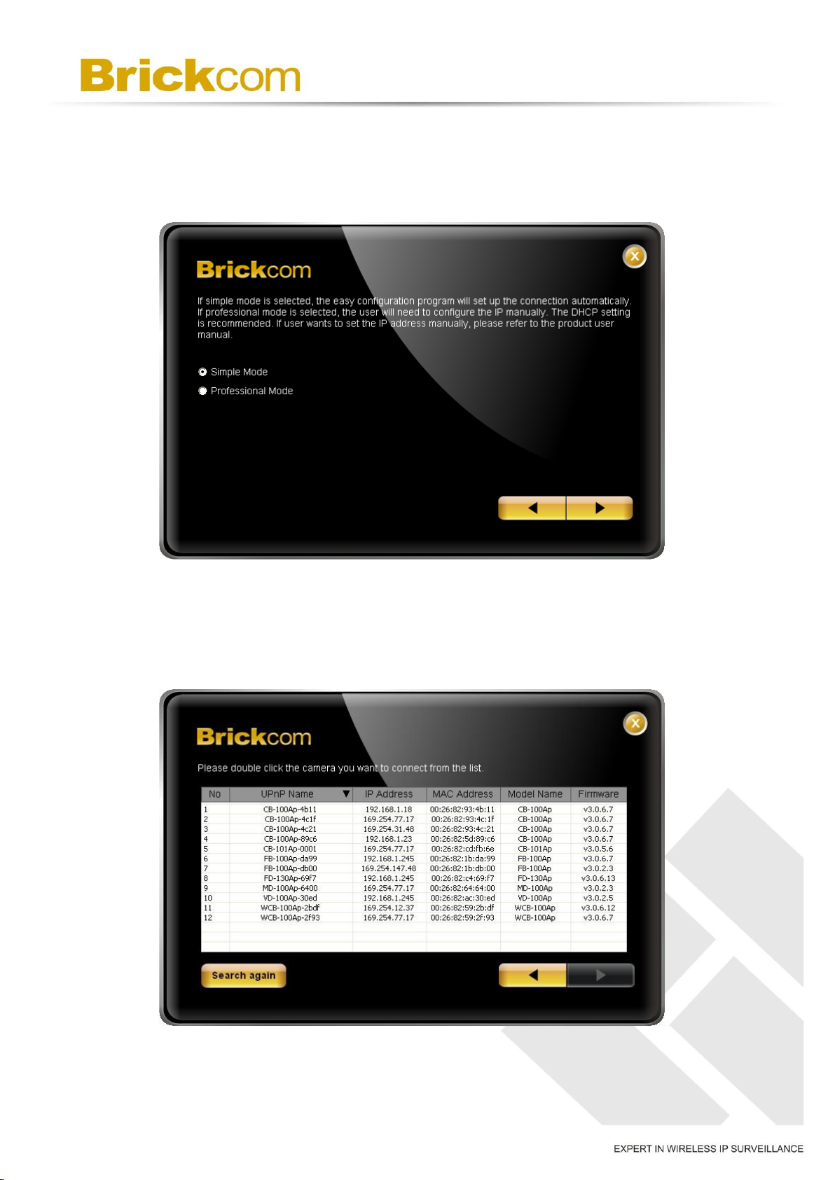
2. Select either <Simple Mode> or <Professional Mode> to obtain the camera’s IP
settings. If <Simple Mode> is selected, EasyConfig will set up the connection
automatically. If <Professional Mode> is selected, the user will need to configure the
IP settings manually.
3. There may be many cameras in the local network. Differentiate the cameras using
their UPnP name. Double click on the camera from the survey list to connect.
18
Page 21
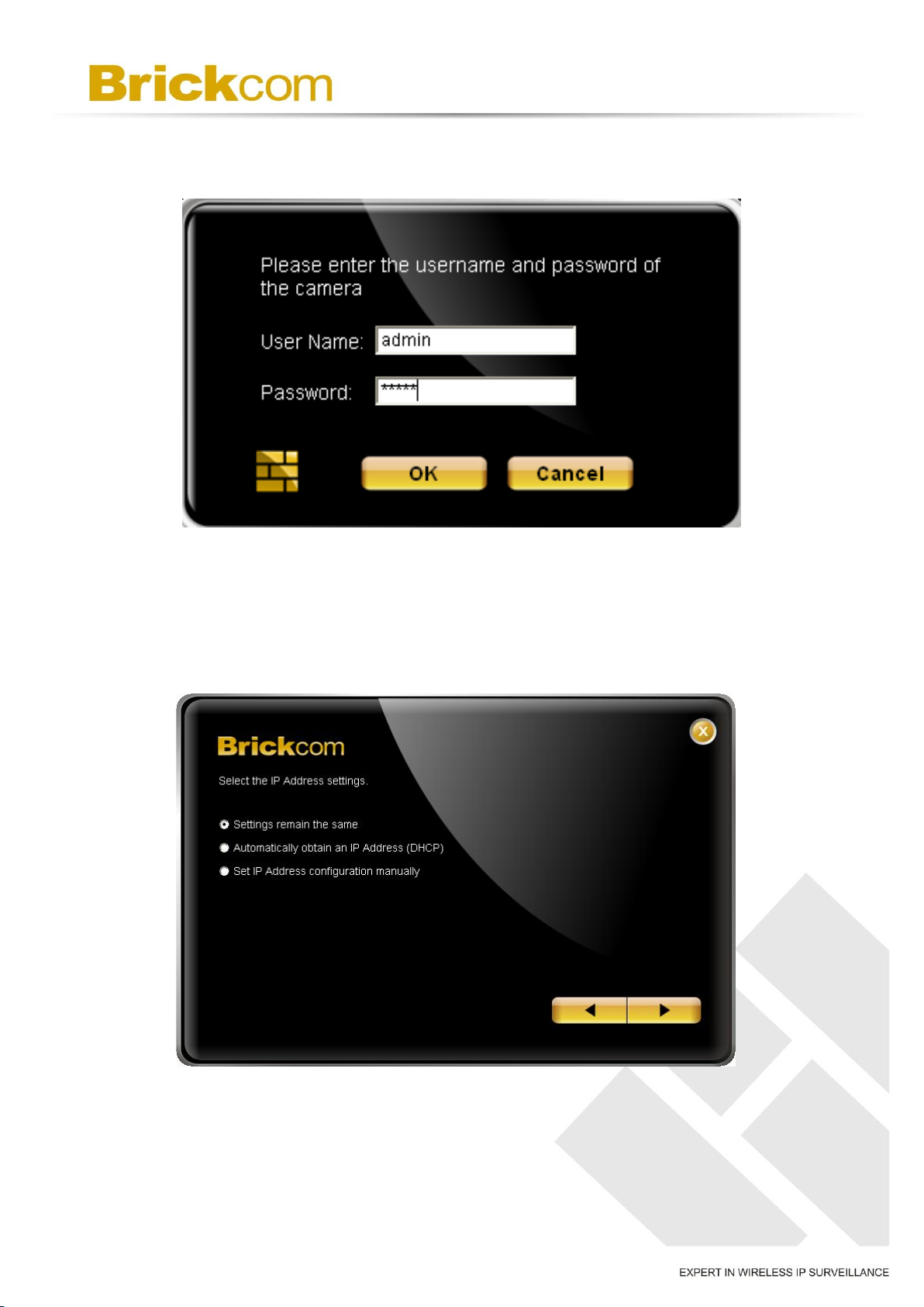
4. Enter the username and password of the camera. For the first-time use, the default
username and password are “admin/admin.”
5. For configuring the IP address settings, select either <Settings remain the same>,
<Automatically obtain an IP Address (DHCP)> or <Set IP Address configuration
manually>. The DHCP setting is recommended.
19
Page 22
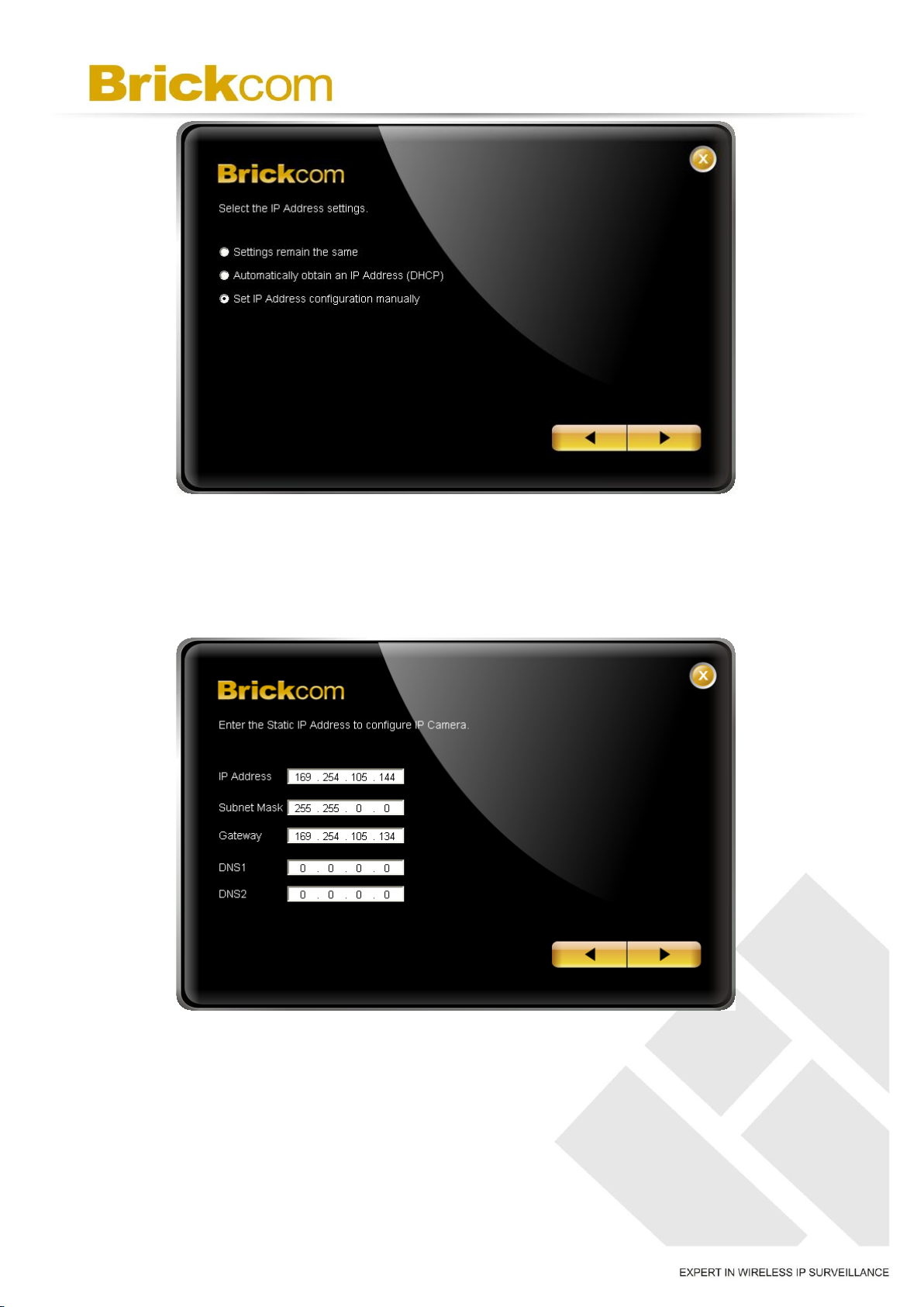
6. If <Set IP Address configuration manually> is selected, the following pages will be
displayed.
20
Page 23
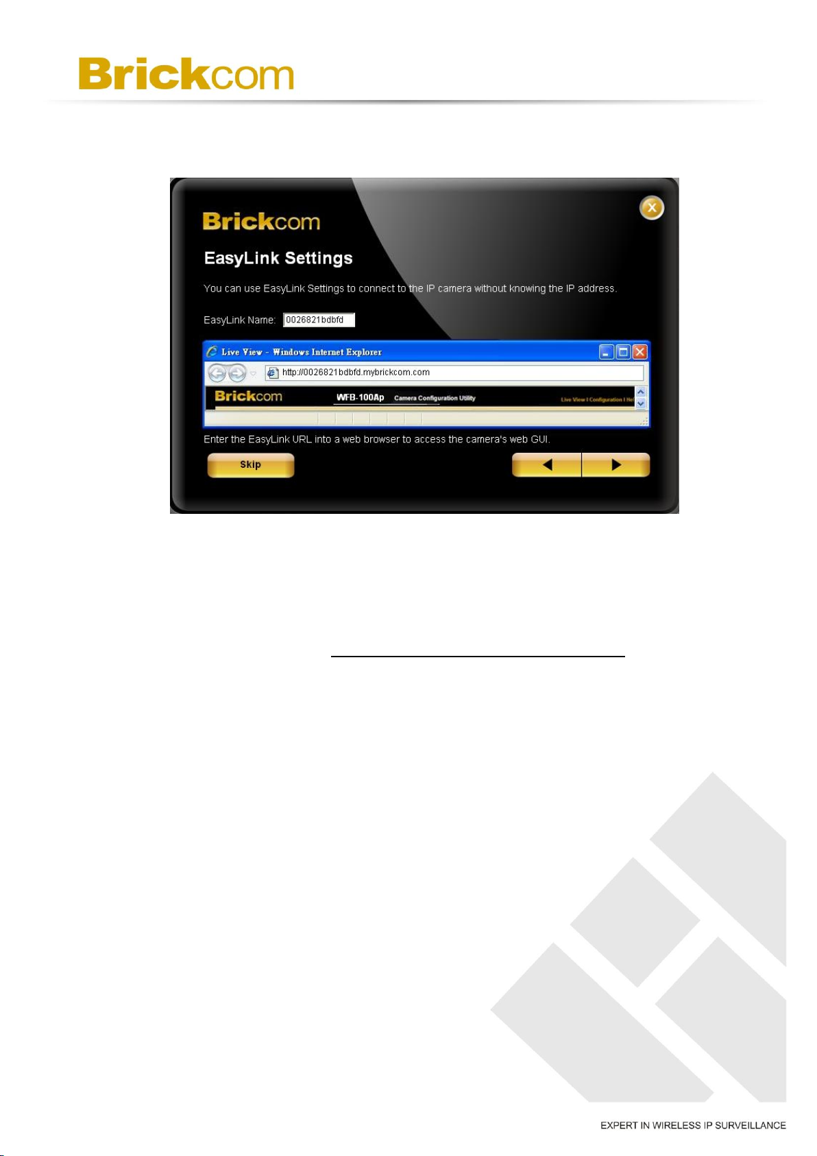
7. If the camera supports the EasyLinkTM function, the following window will be
displayed. Otherwise, this window will not be shown.
*If desired, click <Skip> to skip this setting. EasyLinkTM is a unique Brickcom function
which allows users to assign a unique EasyLink name to map to the network camera’s IP
address. Users can log onto [uniqueEasyLinkname].mybrickcom.com to view the
camera’s web GUI and Live View.
Enter a unique EasyLink name whose length must be between 5-32 characters.
When finished, click the arrow button to continue.
21
Page 24
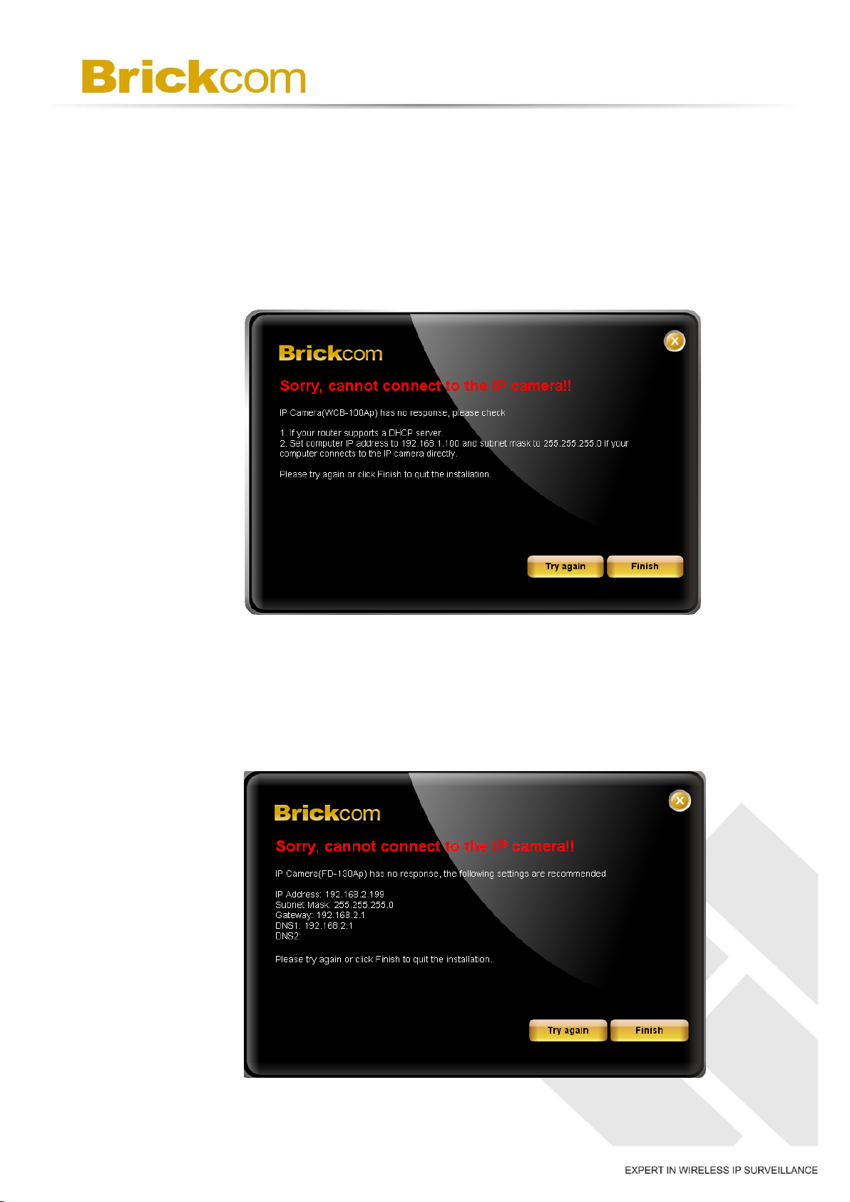
8. When the IP address settings have been configured, the screen will either display a
successful or failed connection message. If the connection failed, either try again or
quit the installation.
If “DHCP IP address settings” was selected, the failure window will be displayed as
below.
If <Static IP address settings> was selected, the failure window will be displayed
as below.
22
Page 25
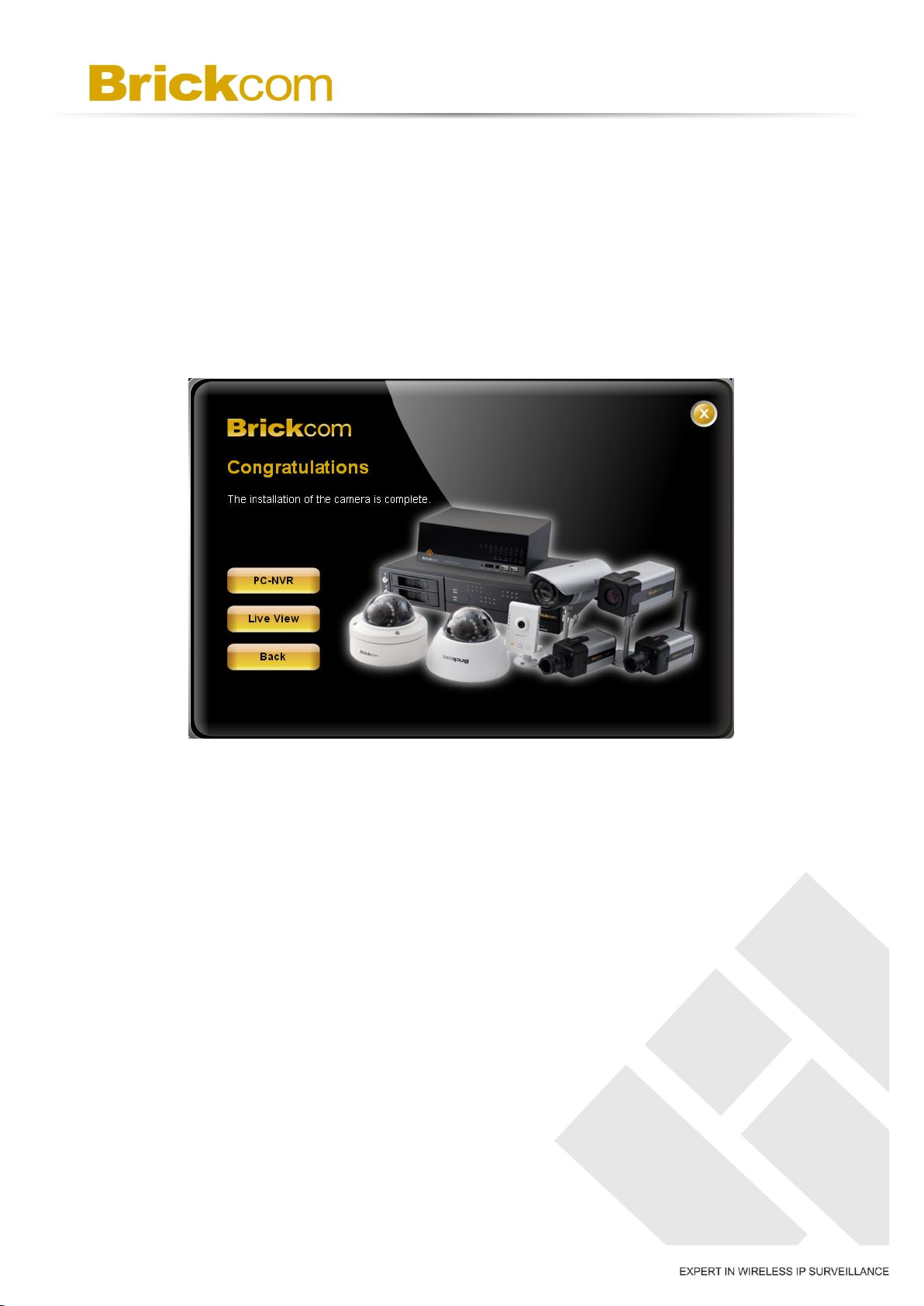
If the connection was successful, the user will see the message: <Congratulations. The
installation of the camera is complete.>
9. When this window is displayed, click <PC-NVR> to start the BRC64 program, <Live
View> to view the live video from the connected IP camera, or <X> in the top right
corner of the screen to close the installation window. If the user starts the BRC64
program, please refer to PC-NVR’s user manual.
Once the installation is complete, the administrator should proceed to the next section
"Accessing the Network Camera" for necessary changes and configurations.
23
Page 26

Chapter 8 - Accessing the Network
Camera
8.1 Check Network Settings
The camera can be connected either before or immediately after the software installation.
The Administrator should complete the network settings on the configuration page,
including entering the correct Subnet Mask, Default Gateway, primary DNS and
Secondary DNS. Ask the network administrator or Internet service provider for the detail
information.
8.2 Add the Password to Prevent Unauthorized Access
The administrator should immediately implement a new password as a matter of prudent
security practice. For the first time, the username and password for the administrator are
assigned as “admin/admin”. After the administrator changes the administrator
password, the web browser will display an authentication window to confirm the new
password. Once the password is set, there is no provision to recover the administrator’s
password. If the administrator’s password is lost, please reset to the original factory
default settings.
The administrator can set up a maximum of ten user accounts. Users will be able to
access the network camera, but will not be allowed to access system configurations.
24
Page 27
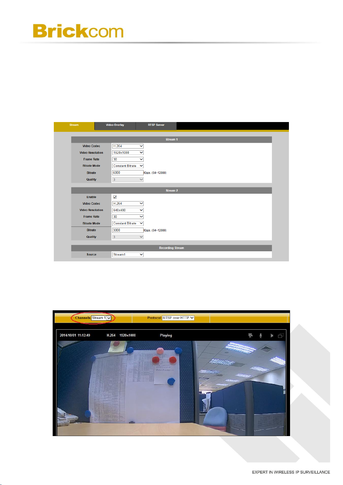
8.3 Viewing Video Streams with Internet Explorer
Step1. Check the Video Stream Settings
On the camera's web UI, please go to Configuration → Camera/Video/Audio → Video,
and you will find the stream settings. Please select the desired setting from the
drop-down menus to meet the application requirements.
Step2. Select the Video Stream for Live View
After finishing the video stream settings, please go to “Live View” and select the stream
you want to view from Channels (Stream1, Stream2, etc.)
25
Page 28
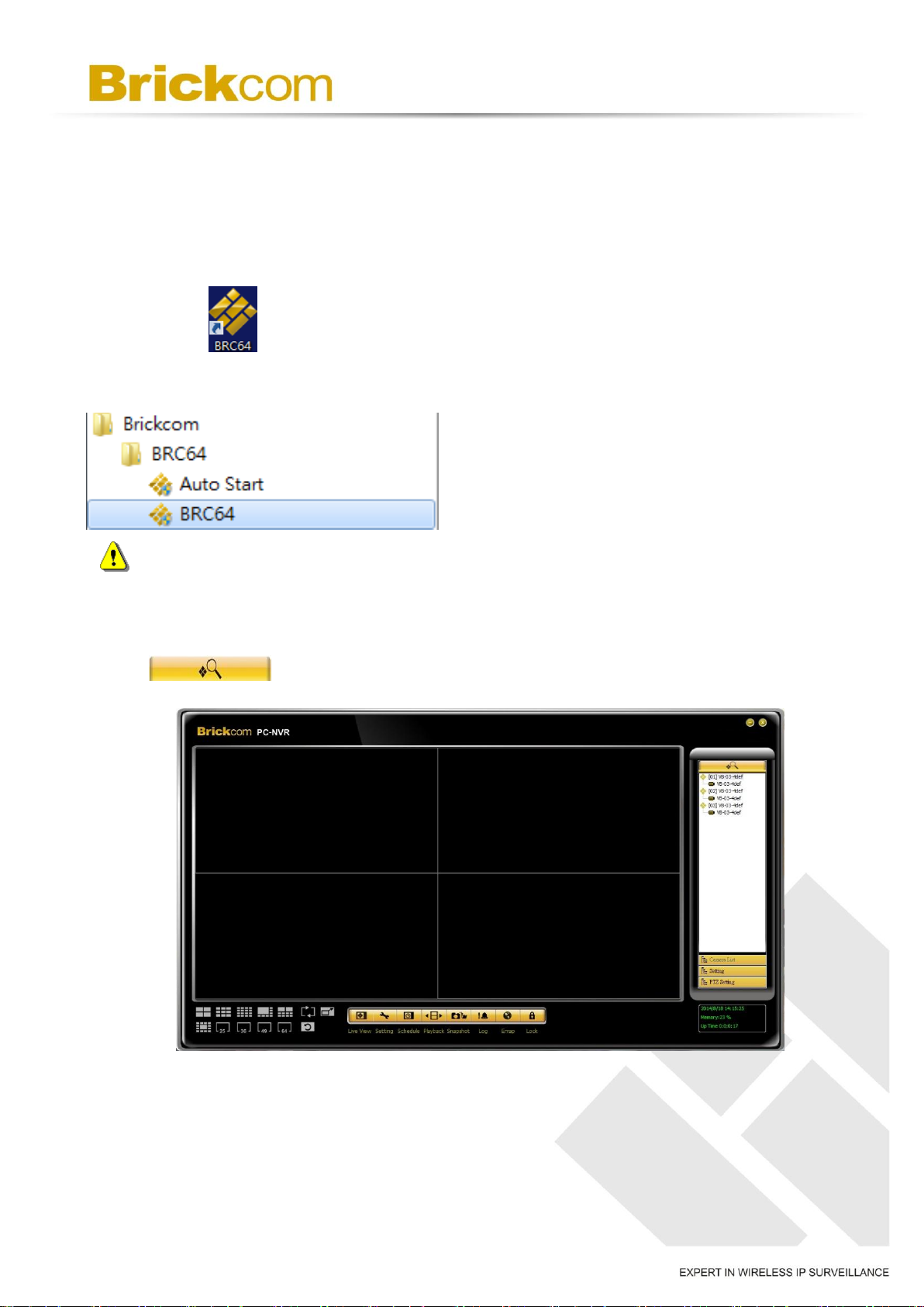
Chapter 9 - Viewing Video Streams
with BRC64
Step1. Launch BRC64
Double click on the Windows desktop to launch BRC64, or click it on the program
menu.
Please make sure the version of BRC64 is v1.2.4.144 or above.
Step2. Search for the Camera
Click on the control panel to start searching for the cameras on the LAN.
26
Page 29
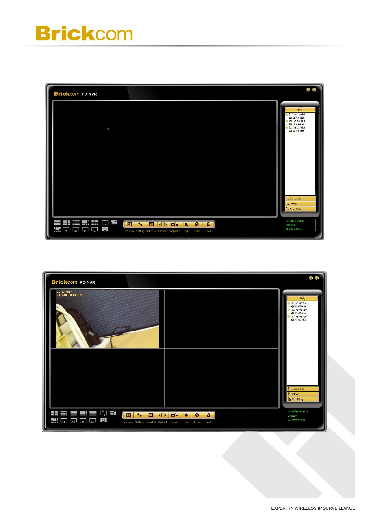
Step3. View Stream
For each video stream you want to view, please select the camera item on the control
panel. Then, drag and drop it to the video matrix for live view.
27
 Loading...