

Page 1
--
--
--
-~-
-
Braun
SuperB
Instructions
for
Use
Nizo801
Nizo561
Nizo481
BRRun
Page 2
Contents Filming with the Nizo 801,
561 and
481
Getting
to
know your Nizo camera
Focal length adjustment
13
We congratulate you on
your
choice of the
(brief instructions)
4
Description
of
Vario zoom lens 13
Nizo camera, a
product
of the
pioneer
Varying the focal length
13
German film camera company . From
now
Drive system
7
Manual focal length
control
on,
your
films
will
be taken with a Super-8
Drive batteries and battery safety box
7 (on Nizo
801) 14
camera built to the highest international
Electric master switch
7
standards.
The Nizo
801,
561
and
481
Checking battery voltage
7
Running speeds (image frequency)
14
models
differ
mainly in the use of zoom
Operating the camera from
an
Slow motion (filming speed switch
1)
14
lenses of differing focal lengths. This
outside
power
source
or
from
an
Speeded-up action (filming speed
manual therefore provides the basic
oper-
storage battery using the Nizo Power Set
8
switch
2)
15
atin g instructions for all three Nizo camera
Holding the camera and operating
Animation techniques 16 models.
the shutter
8
Flash
illumination
for
elapsed
Filming with a tripod, using a cable
time filrhing
16
If you fold back the
double
pages on the
release
8
left and on the right at the end of this
Electric remote
shutter
release
9
The variable shutter
17
manual , you will see the
controls
illustra-
General
description
of variable shutter 17
ted and numbered . The same
numbers
are
The film cassette
10
Fade-ins and fade -outs
17
used below to explain the various
oper-
Film types which may be used
10
Automatic
dissolves
18
ating
functions
briefly, so that you can
Inserting the cassette, checking
The Nizo automatic exposure
rapidly become familiar with
your
camera.
camera
I·oading
10
reduction system
19
We
have confined ourselves to essential
The built-in
filter
10
Extended exposure times
19
instructions
. If you initially set all
controls
Automatic
extended exposure system
20
to the red dots provided, and
do
not con-
Exposure control
11
cern yourself with animated
filming
or
Meter battery
11
Synchronized filming and sound
other
special features of
your
Nizo camera,
Checking voltage of
meter
battery
11
recording
21
you
will
be able to shoot
your
first film
Automatic exposure
control
11
without
giving too much
thought
to the
Manual operation of lens iris
12
Ultra close-up filming
22
«mechanics» of camera operation, and can
devote
your
entire attention to
composing
Range finding and focusing
12
Filters
23
the scenes of your film and
practising
ca-
Adjusting the eyepiece
(diopter
The carrying case
23
mera movements.
compensation)
12
The split-image range
finder
12
Minor defects and remedies
24
Making best use of availabl e depth
of focus
13
4
Page 3
5
..
3
~:
'
'u
0
v,
J :' g,
• 0 •
Page 4
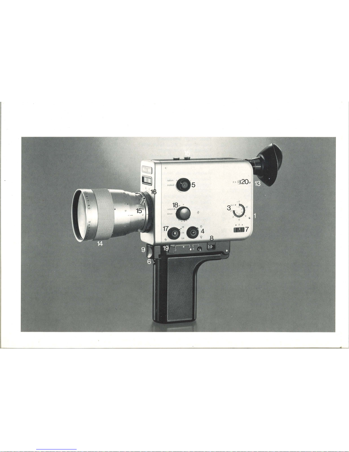
Getting to know your Nizo camera
1. Cassette compartment
A flap secured by a catch
will
be found on
the rear end of the camera. Press the catch
down, open the
flap and slide the cassette
into the compartment.
The first time: do
not
use
force
if
the flap
will
not
shut. Remove the cassette
and
turn
it
round. The
maker
's
label
should
be
visible through the
inspection
window
.
2. Inspection window
This enables you to check at any
time
if
your
camera
is
loaded and if so, with what
type of
film.
3. Film counter
The
counter
returns
automatically
to 0
when you op en the cassette
compartment
flap.
4. Filter switch
Super-8 film stock is designed to match the
co lor temperature
of
artificial
light. Your
camera has a built-in
filter
to adapt it
for
day
light
filming.
When filming in da
ylight
, turn the
filter
selector
to the sun symbol, even
if
using
bl
ack a
nd
white film.
If
you are
filming
in
a
rtifici
al light, turn the
red
triangl
e on the
switch to face the la
mp
symbol.
Warning: when the
artificial
light
filter
is
out
of action, a second signal
will
apear
next to th e
film feed scale above the view-
find
er image.
The
center
of
the
filter
switch contains a
spring,loaded button marked «+ 1
».
If you
keep this button pressed in, the automatic
exposure
control
will
open up the aperture
by one
additional
stop number.
5.
Lens iris control
Exposure
control
is achieved by varying the
iris aperture,
either
automatically
or
by
hand (the iris setting
is
shown on a scale
under the imag e in the viewfinder). In the
center: the
meter
battery voltage testing
button
(2
x 1.35 volt cells in the camera
base).
Set the master
electric
switch 7 to
the red dot. Press the test button. The
aperture
indicator
needle should move
across to the figure 8 on the aperture
scale
under
the
viewfinder
. The 8 is colored red
for
easy identification.
The first
time:
leave the aperture
control
set to the
red
dot
(= a
utomatic
exposure
control)
.
6.
Hand grip lock
The hand
grip
can be swung back out
of
the way.
The
grip
contains
a safety box
for
the 6 x 1.5
volt
AA
penlight
cells which
drive
.
the camera
motor
.
The first
time:
If
the camera does
not
start,
the batteries may ha
ve
been inserted
wrongly into the box. Please
insert
the
batte
ri
es as shown
by
the symbols on the
box.
7. Electric master switch
0 = all
power
circuits
switched off.
This
setting preserves the batteries. Red
dot
=
all
pow
er
circuits
switched on . Black
dot
=
setting
for
checking voltage
of
drive
batter
-
ies. The switch is spring
loaded in this
position . When press
eo
in firmly,
the
aper-
ture
indicator
ne~dl
e
on the scale
under
the
viewfinder
should move
as
far
as
possi-
ble
to the left of the test
mark
8.
If the
poin-
ter
remains to the right of the 8, new bat-
teries are required.
The
first
time : If the camera does
not
start,
make
sure that the master switch is set to
the
red
dot
position
.
8. Outside power source connection
An storage battery
is
available
as
an
acces
-
sory (in
the
Nizo Power Set), and enables
the camera to be driven with a
greater
re-
serve of energy
or
alternatively
direct
from
the mains
power
supply.
9. Shutter release
Can be
comfortably
operated with the in-
dex
finger
of the left
or
right hand. The
drive
mechanism is started
electromagneti-
cally.
The first
time : Do
not
jerk
the
shutter
re-
lease when operating. Do
not
film in
short
bur
sts
(a
good
rule of thumb is to
allow
each
shot
to run
for
5-6 seconds).
4
Page 5
..
5
10. Connection for cable release
This
connection
is
used
if
you wish to
start
the camera
motor
with a cable release,
for
instance if one is built into the
control
arm
of
your
tripod. It can also be used
for
ani-
mation in
conjunction
with the manual
single frame setting of the ca'mera.
11. Connection for electric remote release
The
Nizo remote release (available as an
accessory) can be connected here, and the
camera
motor
started by a built-in solenoid.
12. Continuous
run
switch
This
switch is needed to operate the auto -
matic
single frame filming device. Disengage the switch from its catch, and swing
over ful'ly to the right. The camera
will run
until the switch is moved back.
The
first
time:
Do
not
forget to set
filming
speed
switch 2 to the automatic
single
frame (time lapse) position before
operat
-
ing
the continuous run switch,
or
else
valuable film stock may be run through the
camera accidentally.
•
13. Adjustable viewfinder eyepiece
This
adapts the optical system of
your
camera to suit
your
own eyesight, as on
binoculars.
Turn the
control
until
the line in the
center
of
the
split
image rangefinder in the view-
finder
appears sharp. This
initial
setting
is
important
for
correct
through-the-Iens
range finding.
14. Lens focusing ring
To measure distance and focus the camera,
turn this ring until the vertical outlines of
the
object
being filmed pass smoothly
(without a step) from one
half
of the
split
, image range
finder
in the
viewfinder
to the
other, Always set the zoom lens to the
maximum possible focal length
48,
56
or
80
mm, depending on camera type) before
using the rangefinder.
If you set the lens focusing
and
focal
length
rings to the
red
figures
(colored
for
ease
of
identification), you
will
be able to dis-
regard the focusing
problem
for
most
nor
-
mal shots. Ample depth
of
focus
will
be
provided
for
action
shots which
would
otherwise
call
for a
rapid
reaction on your
part
while filming.
15. Automatic power zoom
The
lens can be zoomed with the built-in
motor
by
pressing a button
while
filming,
or
alternatively set to the desi red focal
length by hand before filming starts. A
word of warning : if you are filming at more
than about
25
mm focal length (tele lens),
you should rest
or
lean
your
hand against
a solid
object
or
surface,
or
stand the ca-
mera on its handgrip. For absolutely steady
tele shots, a
tripod
is the best solution.
The first time:
Zoom
shots
should
be in-
corporated
only
sparingly
into
your
film,
and
are best
avoided
until
you have time to
experiment.
16. The Nizo
801
model only
is
provided
with
manual override for the power zoom
mechanism
On
the Nizo
801
you can
disconnect
the
power
zoom mechanism by turning the
black ring on the lens from the red
dot
back
to
O.
The
long zoom lens lever supplied
with the camera can then be screwed onto
the focal length
control
ring, and the focal
length varied as desired by hand while
actually filming .
17. Filming speed switch 1
(for
slow-motion effects)
This switch enables you to vary the standard filming speed of
18
frames per second,
and to film instead at a semi-slow motion
speed
of
24
frames per second,
or
at
1/3
of
the normal speed, using
54
frames per
second. By pressing the
54
button transi-
tion from
18
or
24
frames per 'second to 54
frames per second and back,
for
special
slow motion effects.
The
first
time:
The 54 frames
per
second
running
speed
reduces exposure time. The
iris therefore opens
and
the depth of focus
is reduced. For this reason you must
try
to focus as
accurately
as possible.
18. Filming speed switch 2 (speeded-up action)
This switch operates the automatic single
frame mechanism, which provides a
conti-
nuously variable time-lapse filming
facility
between 6 frames per second and approx.
1 frame per minute.
Page 6
Set the red triangle on the switch to the
first black square on the semi -circular
sca le.
Operate the
continuous
running
switch
12,
followed by the master switch 7.
Adjust
the setting until the desired filming
rate is obtained.
The black square between the end of the
scale and the red
dot
is the setting
for
manual sing le frame filming, with the shutter
operated by a cable release
or
the elec-
tric
remote release unit.
In
the «autom. '8» position, the filming
speed (image frequency) is
contro
lled
automatically in
accordance
with the
amount
of
light
availab le (automatic ex -
tended exposure system).
The first time: For
normal
filming, leave
the sw
it
ch
set to the
red
dot
.
19. Variable shutler
If you pull back this
spring
loaded-lever as
far
as
the stop while filming, you
will
gradually
fade
out
the picture. If, on the
other
hand, you start to film with the lever
moved fully to the rear, and a
llow
it to slide
forwards slowly
while
the camera is run-
ning, the scene you are
filming
will be
faded in gradually.
The first time: Do
not
move the fade lever
too rapidly.
Reduced exposure (partially closed shut ter): move the lever to the
'/2 position, then
pull down. The lever wi ll engage in this
position.
Increased exposure position: move the
lever fully back and press the lock button.
Move the lever across into the shaded zone
and release the lock button . Note that the
film
im
age will not be exposed until the
automatic
single
frame mechanism advances the film to the next frame. This increased exposure device operates on ly in
conjunction
with the time lapse filming
speeds made possible by the automatic
single frame mechanism (filming speed
switch 2).
The first
time:
After
filming
with the in-
creased
or
reduced
exposure time mecha-
nisms, do
not
forget
to release the variab-
le shutter lever
and
move
it
back to the
normal
setting
.
20.
Automatic dissolves
As you near the end of a shot, press the R
button on the camera . The automat ic disso
lve mechanism
will
fade out the scene
you are filming, wind the film back by the
amount used
for
the fade and halt the drive
motor.
When you are ready to start the shot forming the second half of the scene containing
the dissolve, press the R button on the
camera
and
the
shutter
release. The camera will start to run and the shutter will
automatically open.
You can check the various phases of the
dissolve in the
window
: 0 = ready for
phase 1 of the dissolve (fade-
out
and re-
wind);
R = ready
for
phase 2 of the dis-
solve (fade-in).
The
first
time:
Do
not
forget that a dissolve
is
intended
to provide a smooth transition
between two scenes of your film,
and
time
the shots
accordingly
. .
21. Connection fof electronic flash
You can
connect
a flash gun of adequate
performance
to this socket, and use it to
illuminate
ultra slow
time lapse shots .
22.
On
Nizo
801
and
561
only: pilot tone
cable connector
The
Nizo
801
and
561
models
incorporate
an
oscillator, which can be used to
trans-
mit
a 1000 Hz
contro
l impulse for each
single
or
every fourth frame of film,
depend-
ing on the sound system and tape
recorder
cab le in use.
6
Page 7
7
Drive system
Drive batteries and battery safety box
The
camera
motor
and the
power
zoom
mechanism are
electric
ally powered by six
1.5
volt AA penlight cell batteries. This type
of battery is
obtainable everywhere
for
use
in
transistor
radios.
We
recommend the
use
of
manganese-alkaline cells (for ex-
ample, Mallory MN 1500, Everready E
94,
Ucar
E 94). The batteries are housed in a
safety box in the camera handgrip.
To obtain access to the patteries, press the
button beneath the shutter
release and
swing down the
hal'ldgrip. Pull back the
knurled catch on the
upper
section of the
handgrip. The battery box
will
be partly
ejected. Loosen the
knurled
screws
on the
under
side of the box until the
cover
can
be removed.
Insert the six 1.5 volt cells as
indicated by the
symbols. Repl'ace the
cover and tighten the
knurled screws. The
studs on the box
lid are of
differing
lengths
so
that
the cover can only be replaced in
one position.
Insert
the battery box into
the handgrip and
press down
gently
until
the knurled catch snaps
into position over
the projection on the
box.
If the batteries
have been inserted
incorrectly, the cainera
will not be damaged
but the drive
motor
will not run.
The safety battery
box protects the contacts in the camera against damage caused
by
electrolyte leaking from
old
batteries.
It
is a good idea to obtain a sp'are battery
box
(available as an accessory), especially
when filming in extremely cold
conditions
.
If the batteries in the camera are exhausted
or
too cold to drive the
motor
at full power,
the
complete battery box can be replaced
by the spare unit, which should be kept in
your pocket so
that
the batteries remain
warm.
Master electric switch
When the master switch is set to
0,
the
circuits
powered by the
drive
and meter
batteries are
disconnected
. When set to
the running position (red dot), the batteries
supply a very small
continuous
current
and
will
therefore
slowly
become
exhausted
Voltage
check
•
O
ff
Operatin
g
pos
iti
on
o •
I
J~~fl
even
if
the camera
motor
is
not run.
For
this reason, the master switch should al-
ways be turned to ° whenever the camera
is
not
operated a
prolonged
period . This
will also prevent
the
camera from running
if the shutter
re·lease
is
accidentally
oper-
ated. Note, too,
that
if
the handgrip is
swung back
but
the master switch
not
set
to
0,
the meter battery will continue to
operate at
full
power
.
The
black
dot
indicates
the switch setting
for
checking the
condition
of the drive
batteries.
Checking voltage
of
drive batteries
When moved to the black
dot
setting, the
master
electric
switch is spring loaded so
that it
cannot
accidentally
be left in this
position . To check battery
voltage, push
the master
electric
switch along
as
far as
the
black
dot
and
hold
it
temporarily in this
position. Examine the aperture
scale at the
bottom of the image in the viewfinder; the
Page 8
pOinter should have moved
as
far
as
pos-
sible to the left
(16,
22)
and away from the
red-colored
8,
which acts as a test mark.
If
the pointer remains opposite the 8
or
even to the right of it, all six battery cells
should be removed from the battery box
as
soon
as
possible.
Connection to
an
outside power source
or storage battery using the Nizo Power
Set
If a great
deal of material is to be filmed,
the camera
used on a long
journey
or
the
automatic single frame mechanism operated
for
many days on end to produce
lengthly time-lapse shots, we recommend
the provision of
an
outside
power
supply
using the Nizo
Power Set (available as
an
accessory). The Nizo Power Set can be
obtained with
either
the
Barix
storage
battery
or a dry
type (NC) storage battery.
The carrying case
contains
the recharge -
able storage battery with charging and
mains lead and maintenance equipment,
a special lead to
join
the camera to the
storage battery and a special locking plate
to attach the
tripod
direct
to the camera
base. The storage battery is capable of
running up to
30 Super-8 cassettes through
the camera before recharging is necessary.
By means of the charging/mains lead, the
storage battery can be used in a
«buffer.,
circuit
to
power
the camera from the mains
supply, if a
prolonged
time-lapse filming
session is being carried out. The storage
battery lead
connection
is on the camera
base, next to
·the
variable
shutter lever.
Further
details
are given in the operating
instructions
for
the Power
Set
Holding the camera, operating the
shutter release
All Nizo cameras can be operated with
either the right
or
the left hand. Past the
hand through the carrying
loop
before
taking hold of the grip. The shutter release
can easily be reached and operated with
the index finger.
The large eyepiece
rubber
cup supplied with
the camera will normally position the eye
at the
correct
distance
from the eyepiece
lens.
It also helps to prevent extraneous
light from affecting the
quality
of the view-
finder image. However, no
light
can in any
circumstances reach the film after pene-
trating the viewfinder.
If
you normally wear
glasses, you may
prefer
to use the padded
eyepiece rubber cup, which provides a flatter
support when using the viewfinder. Either
the cushion rubber cup
or
the standard eyepiece rubber cup can be removed and installed
without
difficulty
if pushed over the
projecting
rim on the eyepiece.
The
hand
not
holding the camera is used
to operate
the
focusing ring
or
the
power
zoom. When actual1y filming, the free hand
can also be used to press the camera
gent-
ly
but
firmly
down into the
other
hand.
Warning: While filming, do
not
accidentally
press the voltage check button in the lens
iris
control
switch,
or
else
incorrect
expo-
sures may result.
Using a tripod and cable release
Filming with the camera mounted on the
tripod
always g·ives good results,
since
the
picture
on the
projection
screen is
after
-
wards much steadier.
In
addition, a
tripod
greatly
simplifies
camera pans, zooming in
and out, manually controlled stop-motion
shots using the single frame mechanism
and general filming at focal lengths above
40 mm.
A threaded
hole
is provided in the base
of
the
handgrip
for
the tripod screw. In
other
words, the camera
is
attached to the
tripod
head with the
handgrip
swung down into
the normal filming
pOSition. If the camera
drive
is to be operated by a cable release
attached to the tripod arm, the release
should be screwed into the first socket
8
Page 9
9
from the right on the camera base. If you
wish to film
single frames
without
using
the automatic
single frame mechanism,
you can shoot each frame by operating the
cable release once.
In
this case, the red
triangle
mark
on filming speed switch 2
must be turned to coincide with the
first
black square next to the red dot.
•
•
timer
If the camera base
is
to rest
directly
on the
tripod
head, the handgrip containing the
batteries must be swung away.
In
this case,
the outside
power
supply
will
be needed
(see section
«Nizo Power Set»).
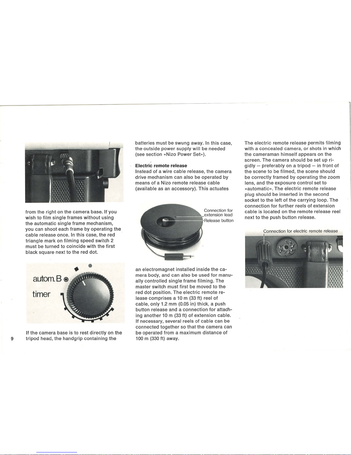
Electric remote release
Instead of a wire cable release, the camera
drive mechanism can
also be operated by
means of a Nizo remote
release cable
(available
as
an
accessory) . This actuates
Co
nnection
for
pytp
n."nn
le
ad
!;;::::::~
RE~le,"s
e
button
an
electromagnet
installed inside the ca-
mera body, and can
also be used
for
manu-
ally controlled
single
frame filming. The
master switch must first be moved to the
red
dot
position. The
electric
remote re-
lease comprises a
10
m (33 It) reel of
cable, only 1.2 mm (0.05 in) thick, a push
button release and a
connection
for
attach-
ing another 10 m
(33
It) of extension cable.
If necessary, several reels of cable can be
connected
together
so
that
the camera can
be operated from a maximum distance of
100
m (330 It) away.
The
electric
remote release permits filming
with a concealed camera,
or
shots in which
the cameraman himself appears
on
the
screen. The camera should be set up rigidly
- preferably on a tripod - in
front
of
the scene to be filmed, the scene should
be
correctly
framed by operating the zoom
lens, and the exposure control set to
«automatic» . The
electric
remote release
plug should be inserted in the second
socket to the
lelt
of the carrying loop. The
connection
for
further
reels of extension
cable is located on the remote release reel
next
to the push button release.
Connection
for electric
remot
e release
Page 10

The film cassette
Suitable films for your camera
The Nizo
801,
561
and
481
models are
designed to accept Super-8
film cassettes.
When the camera is
loaded, the automatic
exposure
control
is
set to the film speed
of
the film stock inside the cassette. The fol-
lowing film
speed ranges are available:
Artificial
light
color
film from 13 to 23 DIN
(= 16 to 160 ASA)
Daylight
color
~ilm
from
11
to
21
DIN
(=
10
to
100 ASA)
Black-and-white film from
11
to
21
DIN
(=
10
to 100 ASA)
Inserting cassettes, checking camera
loading
Open the flap on the rear end of the ca-
mera and insert the cassette
into
the
com-
partment with the film aperture at the front.
The
circular
recess on the cassette should
be on the control knob side of the camera.
If the cassette is inserted the wrong way
round, the
flap will
not
close. In
this case,
do
not
use force, but remove the cassette
and insert it the
other
way round
as
de-
scribed.
The cassette
itself
automatically
adjusts
the exposure
control
to suit the type of film
stock being used. The film
counter
returns
to the start position when the cassette
compartment
flap
is
openeed. The
counter
also runs when there is no cassette in the
camera. The
outer
scale
indicates
the
length
of
film still available in meters, the
inner
scale in feet. The smooth side of the
camera (opposite to the side incorporating
the
controls)
includes a window
which
enables you to check
whether
the camera
is
loaded and
what
film stock
is
being used.
If film
is
passing
out
of the cassette,
through the camera and being returned to
the cassette
correctly, a red illuminated
signal
will
appear
at
intervals above the
viewfinder image. As the
length of available
film
is reduce'd, the intervals between the
light
signals
will
become
longer. When the
end of the
film is reached, the
indicator
lamp above the
viewfinder
image will re-
main on
continously. You can check
that
the film has been run completely through
the camera by
looking
for the word «Ex-
posed
..
in the film aperture of the cassette
after
removal.
The built-in filter
Super
-8
color
films
are manufactured to
suit the
lower
color
temperature of artificial
light.
A built-in conversion
filter
(red) ad-
justs the
color
temperature to suit daylight
filming
when the red
triangle
on the film
switch
is
turned to face the sun symbol.
When filming in
artificial
light, the red
mark
should be placed
opposite
the lamp sym-
bol.
The
special
setting
is
indicated
by a
red
lamp
symbol
on the right, above the view-
finder
image, when the camera is running.
Note this
symbol
if
you film in daylight, to
prevent
a heavy blue tinge on
your
films
when developed.
For
all black-and-white film and
daylight
color
films, the filter switch
mark
should
always
be
left
against the sun symbol.
10
Page 11

11
Exposure control
By pressing the button
marked" + 1»
in the
center
of
the
filter
switch, you can film with
the automatic exposure
control
still in
operation, but with the
lens
aperture 1 stop
wider
open than normal. This
corrected
setting remains in effect
only
when
the
spring-loaded
button
is
pressed.
The
button should be used when the
more
important
elements in the scene you are
filming
are
in
shadow, and
other
areas
brightly
lit. This will usually
occur
when
filming
against the sun. The 'plus-one' ex-
posure
correction
device
is
also useful
when attempting to film
particularly
dark
subjects
in overcast conditions.
Meter battery
The
CdS automatic exposure
control
is
powered by two 1.35
volt
Mallory
PX
625
cells
. The battery
compartment
is in the
camera base and can
be reached by swinging back the handgrip.
The compartment
catch can be opened
by using a coin in the
screw
slot. The plus
(+)
symbol on the
first battery to be in
serted
should face to-
wards the base of the
battery compartment,
the
+ symbol on the second cell should be
touching the end of the first battery; if the
cells are
incorrectly
inserted, the automatic
lens iris mechanism
will
not operate. Sym-
bols are provided in the battery
compart-
ment to show how the batteries should be
inserted
correctly.
Checking voltage of meter batteries
First set the mast er
electric
switch to the
red dot, then press the button in the
center
of the exposure control knob. The pOinter
a
utom.
manual
Checking
meter battery
on the
scale below the
viewfinder
image
should move across as
far
as
the
figure 8
(colored red
for
ease
of
identification). If
the pointer remains more than its own width
to the
right of the
8,
two new meter battery
cells should be inserted.
If
the
pointer
comes to rest to the left
of
the
figure
8,
unsuitable (e.g. 1.5 volt) cells must have been
inserted.
In each case,
incorrect
film expo-
sures
will result.
Automatic exposure control
The CdS
automatic
exposure system of the
Ni
zo camera measures light passing
through the
lens. The meter readings can
be seen on the
scale beneath the view-
finder
image. Note
that
the automatic ex-
posure
control
system only operates accu-
rately when the camera
is
loaded with a
film cassette. Furthermore, it is impossible
to
compare
the reading shown
on
the
builtin scale with those obtained using a separate exposure meter (even a good
quality
unit
from the same manufacturer, Gossen).
This
is
because the Nizo exposure meter
takes into
account
the varying focal lengths
of the zoom lens, the
light
absorbed by the
numerous
elements in the zoom lens and
the camera
viewfinder
prism.
In
other
words, the
built-in exposure
control
system
has been
accurately
matcheQ to record the
light
actually falling on the film in the Nizo ·
camera.
If the pointer is opposite the left or right
warning marks at
either
end of the scale,
the filmed results may still be satisfactory,
but
correct
exposure cannot be guaranteed.
If the
light
is too strong, remember that
your
camera has a reduced exposure time
facility; if very little
light
is
available,
the
corresponding
extended exposure device
can be used (both
of
these systems are
described in
the
section covering use of
the
variable shutter). Alternatively, more
sensitive stock such as Ektachrome
160
Page 12

may be used
or
the scene illuminated with
halogen floodlights .
Manual control
of
lens aperture
The automatic system can be switched
off
and any desired aperture setting selected
by hand.
The
exposure
control
knob must
first be turned from
«automatic» to «manu-
al».
The pointer on the exposure scale in
the
viewfinder
will now respond to rotary
movement of
t~e
control
knob .
In
this way the exposure values calculated
by the automatic system can be corrected,
for
example if the most
important
part of
the scene
is
considerably
lighter
or
darker
than the surroundings .
The
light
emitted by
the
object
to be filmed should then be
measured with the automatic exposure system by bringing the camera much
closer,
or
else by zooming in on the
object
before
taking a reading, so that the
surroundings
are eliminated. The iris setting recorded by
the exposure meter in the
viewfinder
should
then be selected by hand.
Example: The automatic exposure system
indicates figure
16
when filming a
subject
in the
middle
of
an
area covered with snow
and in
bright
sunlight. If the scene is
actually filmed at this exposure setting, the subject
will be far too dark, as the camera
will
expose the surrounding snow area
correct-
ly. In
other
words, the exposure requires
correction
for best resu Its.
Another
example: When filming subjects
against the
lig'ht, they will normally appear
as
silhouettes;
if
you wish to bring
out
the
full details of
your
subject
on the screen,
turn round before starting to
film and mea-
sure exposure 'with the
light'. Select this
exposure
value manually and then film
your
scene against the light.
Always remember to return the exposure
control
knob from «manual» to «automatic»
after you have
completed
a specially ex-
posed shot
0;
this kind.
In
most cases requiring additional expo-
sure, the
«plus 1
II
control
(described in the
previous section)
will
normally
enable the
desired
results to be obtained.
Rangefinding and focusing
Viewfinder eyepiece adjustment
(diopter compensation)
Before
the through-the-Iens rangefinding
system can be used, the viewfinder must be
adjusted to
suit
the cameraman's eyesight
(as with binoculars). The eyepiece of the
Nizo camera is provided with a
knurled
ring. Turn this ring'until the horizontal division across the center to the rangefinder
appears
perfectly
sharp. This
wHI
be easier
if the camera is kept pointed at a
plain
background (walls, sky). The
adjustment
can be carried
out
at any focal length
or
focus
setting.
The split image rangefinder
The
split
image rangefinder operates with
two measuring prisms which
appear in the
center
of the viewfinder
as a circle
divided
by a
horizontal line.
If
the vertical
outlines
of the
subject
being filmed are displaced
to
one
side as they cross the horizontal
line
of the rangefinder, the focusing ring on
12
Page 13

13
the lens should be turned until the vertical
outlines appear uninterrupted.
Before using the rangefinder, always
select
the longe
st
available focal length
(80,
56
or
48 mm, depending on the zoom lens
fitted
to your Nizo camera).
Accurate
rangefinding and
focusing
is
of
particular
importance when
filming
at
long
focal lengths (from about
30
mm upwards),
filming
closeups at less than 3 m
(10
ft)
distance, using add-on adapter lenses
or
shooting in bad
light
(with the lens iris
wide
open).
Making best use of available depth
of
focus
The
Super-8 film format has been designed
to provide ample depth of focus. This can
be seen from the depth of focus chart supplied with camera. At its widest angle
(7
or
8 mm), and up to average focal lengths
of
about
15
mm, the depth of focus of the
zoom lens makes absolutely accurate focusing unnecessary
for
average shots
(even when filming at
wide
apertures) . The
4 m mark in the lens focusing ring and the
15
mm
mark on the zoom lens focal length
scale are
colored
red. If you fi.lm at these
settings , your pictures
will
be sharp from a
distance of 1.
74 m (5
.7 ft) to infinity, even
if
poor light
conditions
cause the automa-
tic
exposure system to open
up
to aperture
setting
4.
This generous
depth
of focus
will
prove of great value when you have no time
left to take
an
accurate reading on the
rangefinder.
At
shorter focal lengths the
depth of focus is
incr
eased, whereas longer
focal lengt hs have very
little
depth
of focus.
This is the reason why
your
shots may
not
remain sharp
if
you zoom from wide angle
to telephoto end of the focal length scale.
Selecting focal length
General description of zoom lens
The zoom lens (actually a «variable focal
length
lens») enables you to film entire
sequences
incorpor
ating general wideangle shots , semi-clos eups and extreme
closeups if required,
without
changing the
position of the camera. The zoom lens uses
special individual lens c
lu
sters to provide
a variety of focal lengths and filming
angles.
On
the Nizo S
800
zoom lens, the
acceptance
angle of the lens varies be-
tween
42
° and 3°50'. The longer the focal
length at which you are filming, the more
important
it becomes to hold the camera
absolutely steady.
At
focal lengths above
approximate ly
40
mm, you must
support
the
camera
or
your
hand absolutely
firmly
if
you are not using a tripod.
In
addition, the
automatic
power
zoo m enables you to imi-
tate tracking shots,
for
which the camera is
normally mounted on a mobile dolly.
Varying the focal length
You can sel
ect
the desired focal length be-
fore
start
ing
to
film by moving the small
handle of the focal length sca le. This enables you to
start
your
shot at the desired
focal length
without
wasting film.
The
control
buttons
for
the automatic
power
zoom are
locat
ed on the housing of
the Nizo camera. The black knob nearer the
lens reduces the focal length (wide ang le),
the green
knob
on the eyepiece side in-
creases the focal length (telephoto).
Page 14

There are two power zooming speeds.
If
either of the power zoom
control
knobs is
pressed
only lightly, the focal length
will
change slower than
if
the knob is pressed
more
firmly. Tracking and zooming appears
still smoother on the screen if you film
these shots as 24 frames per second.
Manual zoom
control
(on Nizo 801)
A special feature of this Nizo model is the
ability to switch ,off the automatic
power
zoom and vary the focal leng·th with a lever
(supplied
with the camera). Hand zooming
enables you to determine the speed of
apparent
movement accurately, and also
permits very rapid zooms during a shot by
moving the
lever round
as
fast as possible .
The lever should be screwed to the
mount-
ing on the focal length scale. The
power
zoom mechanism is switched
off
(and the
lever becomes easier to move) when the
mark on the
black knurled ring between the
focal length scale and the camera body is
turned
fully
clockwise
until opposite the 0
mark on the body.
Camera running speeds
Slow
motion
facilities (filming speed
switch 1)
The
normal running speed of the camera
is 18 frames
per
second, each frame being
exposed
for '/43rd
of a second . Any
filming
speed above
18
frames per second setting,
will result in a slow motion effect, and all
filming
speeds below
18
frames
per
second
wil'l
produce
a speeded-up effect if
projec-
ted at the normal setting.
With the aid
of
filming speed switch
1,
you
can change from the standard running
speed of
18
frames per second to the
slow
motion
speeds of 24
or
54 frames per se-
cond
. If film
shot
at 24 frames per second
is
projected
at
normal speed, all move-
ments
will appear '/Jrd
slower. This is
not
the same as genuine slow motion,
but
is
useful
if
the camera
is
moved over a long
distance,
for
example during a long pan
or
when filming from a
car
being driven along
a rough road .
54 frames
per
second is a genuine slow
motion speed. When projected
at
18
frames
per second, scenes
win
be prolonged to
three times
their
original length. Fast move-
ments
filmed in this way can be studied at
leisure
during
projection . Since one se-
cond's
filming time yields three seconds
on the screen,
filming at the slow motion
speed is sometimes a way to gain a better
impression of sudden
or
very
brief
events.
The automatic
slow motion device on
your
14
Page 15

15
Nizo camera means that you can
select
the
slow
motion filming speed
without
the
slightest delay when you need it. The black
button in the
center
of filming speed switch
1 enables you to pass smoothly from 18
or
24
frames per second to
54
frames per se-
cond
and back.
At
54
frames per second, the individual,
frames are' exposed
for
only
l/129th
of a
second. To compensate for this, the iris
opens by approximately
1.5 numbers . Un-
der
difficult
exposure
conditions
this
could
mean that inadequate depth of focus is
available.
If
you have sufficient time avail-
able,
it
is therefore best to take a
quick
rangefinding reading at the max imum focal
length
you intend to use.
Speeded-up filming (filming speed switch 2)
With the aid of filming speed switch 2 (an
automatic
single frame filming device)
your
Nizo camera provides facilities for
time
Automatic single-
Sing
le frames using cabl
e
fr
ame exposu
re with
or remote rel
ease
automatic extended /
exposu
re contr
ol
• .
--Standar
d speed
\
autom.B
®
timer
a
pprox. 1 frame
per mi
nut
e
a
ppro
x.
6 fram
es
pe
r seco
nd
lapse filming at any speed between 6 frames per second and 1 frame per minute
(minimum). Note however
that
tolerances
in manufacture may vary between individual cameras, and result in a
slight
further
increase in the
interval between exposures.
For this reason the
scale
for
filming
speed
switch 2 cannot be
accurately
'calibrated in
frames per minute. For
practical
time-lapse
filming, it
is
so easy to establish the inter-
val between one
or
two frames that the
extra cost of
an
absolutely
accurate
timing
device has not been passed onto you.
The fully-automatic Nizo time-lapse
filming
system not
only
takes
care
of the actual
film
transport
but
also
controls
exposure
accurately. For this purpose,
filming
speed
switch
1 must
be
set to 18. After this,
the
Nizo camera can be left to operate entirely
unattended, provided that ample
electric
power and film stock is available.
When the mark on speed switch 2 is oppo -
site the first
black rectangle on the semi-
circular
scale
(not
the
separate black rec-
tangle, which identifies the position
for
manual single frame filming using the cabl'e
release,
nor
the «autom. 8» position, which
is
for
automatic extended exposure control). running speed will be six frames per
second and the action on the screen
will
appear to take place at three times its
nor
-
mal speed. The Nizo camera will beg'in to
operate in this case as soon
as
the contin -
uous run
release on the base next to the
carrying
loop
attachment is lifted away
from its catch and swung
fully to the right.
The
normal
shutter
release
on
the hand-
grip
need not be pressed.
• •
;--".
~
0·
II I
. 'I ,
• . I
' . .
....
';C~"
f. ' .
)1
.,
.. ' ...
\'
.. \\' ,
.
,.
As you turn
filming
speed switch 2
further
to the right, the interval between frames in-
creases.
Two
frames per second,
for
exam-
ple, represent action speeded up nine
times in
relation to the original scene, If the
Nizo is used to
film
only
one frame per
Page 16

minute, the complete action taking place
during one hour will be shown on the
screen in
3.3 seconds
if
the
projector
is
running at
18
frames
per
second (speeded
up
1080 times).
If you use a filming speed between 6 and
approximately 2 frames
per
second, it is
.
not
absolutely necessary for the camera to
be attached to the
tripod
. However, you
must
hold
the camera very steady, avoid
panning
or
tracking with the zoom lens and
remember that
in
order
to obtain 1 second
of viewing time
on
the screen you must
shoot for
3-9
seconds.
Genuine time
lapse cine photography, on
the
other
hand, calls
for
the camera to be
mounted
absolutely rigidly on a tripod. As
a temporary measure, the Nizo can be
rested on its handgrip , but remember that
this
will
limit
you to the field of view
obtained where the camera happens to be
resting.
Animation
If Single frames are exposed at prolonged
intervals, you
will have time to rearrange
the position
of
inanimate
objects
between
each exposure. For instance, you
could
raise
or
lower
the arm of doll by a small
amount each time
or
push a matchbox a
small distance further across a table these are just two
simple examples. When
these
single exposures are
projected
at the
normal continuous speed of
18
frames per
second, the inanimate
objects
come to life
on
the screen. The
doll
waves her arm and
the match box
travels to and fro across the
table.
For all shots of this type, the camera must
be mounted
absolutely rigidly. It
is
best
for
it to be attached to a substantial tripod. If
the camera position is moved
accidentally
halfway
through
a shot, it is best to change
to a
shot
taken from another viewpoint
or
at another focal length in
order
to disguise
the
jump
in the action. The camera shutter
can be
operated
manually with a cable'
release
or
by means of the
electric
remote
release. However, you can also set the
automatic
single frame device to make exposures at suitable intervals, so that you
need not move backwards and forwards
constantly between the camera (to expose
each
single frame) and the
object
you are
filming (to
alter
its position slightly). All you
need to do is to
select
a filming interval at
filming speed switch 2 which gives you
sufficient
time
to rearrange
or
move the
object
you are filming.
Flash illumination for time lapse filming
Since the interval between exposures in
this type of
single frame
filming
is
quite
long, each separate exposure can
quite
easily be illuminated by means of
an
elec-
tronic
flash gun of adequate power, which
at the same time supplies a natural
light
at
a
color
temperature
similar
to that of day-
light. A
further
advantage is that
objects
sensitive to heat (plants, thin gels
for
ani-
mated
films, etc.) are not continually ex-
posed to the heat of spotlights
or
photo-
floods. Your Nizo camera is therefore
pro-
vided with a connection for the flash gun
synchronizing
cable (at far left of camera
base).
Connection
for electronic
flash
The
electronic
flash
unit
must be of ample
capacity
since
18
flashes are required to
illuminate one second's filming and should
also
be capable of repeating its flashes
frequently enough for lengthly series of
single shots to be filmed. The flash gun
must have recycled, ready for the next shot,
before the camera
timer
has advan.ced the
film.
Braun offers three
electronic
flash guns (all
equipped with a swivel reflector) which
meet the requirements. The Braun F
800
is
a
large, two-section professional
unit
which
can
supply
up
to
400
flashes (depending on
the storage battery used) at minimum inter-
16
Page 17

17
vals of two seconds. Special features: the
Braun F
800
can be operated by the so -
called
duplex
system from the mains when
making animated
or
time lapsed films; this
greatly increases its capacity. In
addition
,
its storage battery cari be used
as
an
out-
side
power source together with the camera
supply
lead , if the Nizo ZSSA cable is in-
corporated
into the setup.
The
single-
unit
Braun
2000
VarioComputer
flash gun is currently avail able in three models: F
022, F 027
and
40
VCR. The
only
difference
between these is in the guide
numbers
of 31,
38
and
40
respectively for
21
DIN film. The
power
consumed by these
flash units depends on the filming
distance
and also by the amount of
light
absorbed
by the
objects
being filmed. At a filming
distance
of 1 meter and with a background
which does not absorb too much
light, flash
intervals
of approx. 1 second can be re-
peated about
1000 times (type F 027).
Practical
hints
for
Nizo filming using elec -
tronic
flash:
The
light
produ ced by the
electronic
flash gun has th e same
color
temperature as daylight. The
filter
switch
on
your
Nizo camera should therefore point
to the sun
symbol.
The flash intervals must be
shorter
than the
time
lapse interval selected at filming
speed switch 2. .
The
lens iris on
your
camera must be
opened by one stop more than the expo sure
calculator
on the flash
unit
states,
since the
light
splitting prism in the Nizo
camera and the
exceptionally
large
number
of elements in the zoom lens must be taken
into
account
(see «manual
control
of lens
aperture»).
The
variable shutter
General description of variable shutter
mechanism
The
variable
shutter
is the <<light trap» of
your
film camera. It is a
disc
rotating in
front
of the film gate. While the
disc
is cov-
ering the gate, the
film
is
advanced by one
frame. When the
cutout
in the disc is
oppo
-
site the gate,
light
can strike the surface
of
the film.
On
the Nizo cameras the cutout on
the shutter
disc
can be con·tinuously varied
in size
while the
shutter
is operating, so
that fade-in and fade-out effects can be
produced. In
addition, deliberate reduction
of.
the shutter area (size of cutout) reduces
the exposure
time
if
this proves necessary,
or
alternatively the exposure
time
can be
prolonged by stopping the shutter in the
open position in
front
of the film gate.
Fade-in and fade-out effects
To fade out a scene, hold the camera handle
in the right hand. With the
other
hand,
Page 18

move the variable shutter lever (at
left
of
camera base, next to shutter
release)
smoothly
and slowly back
as
far as the rear
stop, while the camera
is
still running. After
this, stop the camera
motor
by removing
your
finger
from the shutter release. Only
then should the variable
shutter
control
lever be allowed to return to its original
position.
To produce a fade-in effect, the variable
shutter lever
shCluld be pulled fully to the
rear before the camera
motor
is started.
Next, press the shutter release and
allow
the variable shutter lever to move fully forwards at much the same slow, smooth rate
as used
for
the fade-out.
In
most cases, the
fade-out of one scene will be followed by
the fade-in of the next scene .
Automatic dissolves
A smooth transition between two scenes
can be obtained by fading out, rewinding
the length of film used for the fade and
fading in the new scene over the top of the
last few frames of the previous scene. The
automatic dissolve mechanism on
your
Nizo
camera ensures that the fade-out and fadein sections of the dissolve
coincide
exactly,
and
is
thus capable of
producing
reliable
and smooth dissolves entirely automatically.
Dissolves
should
be
performed
only
at
18
or
24 frames per
second
running
speed.
You must operate two
controls
to produce
a dissolve. To start the process, press the
R button on the camera
for
at least 1 second at the end of a scene. Then release
this rewind button and also the shutter
release. The
next
stage in the process
is
automatic: the
scene
is faded out in 3.5
seconds (63 frames) and this precise length
of film rewound into the camera . Finally,
the
motor
stops automatically.
The camera
will
not
restart unless the R
button is
pressed
in
addition
to the shutter
release.
In
other
words, the next scene must beg'in
with a fade-in, and this should be taken into
account
when
determining
the length of
the shot.
You will
appreciate
that
after a fade-out
has been filmed and the film rewound, the
necessary fade-in
to
complete
the dissolve
must
follow
or
else the filni will be overexposed and spoiled. The automatic mechanism on the Nizo camera ensures that you
do not forget to
complete
the dissolve. A
further indication is provided in the
window
above the film
counter:
if a R is visible on
black background, the film has been
re
-
wound, and is ready
for
the fade-in forming
the second part of the dissolve.
D
on
a white background indicates normal
camera operation . A dissolve can then be
produced at any time by the fade-out and
rewound
process described
above.
Instead of the control button, a camera
release can be used: this is screwed into
the socket
next
to the button.
Warning: Always
avoid
starting a dissolve
at
the
end
of
the film run,
as
it
cannot be
guaranteed
that
the complete dissolve
will
take
place
correctly..
This is explained by the fact
that
for
each
dissolve the camera rewinds a section of
film approx.
27 cm (10.6 in) long into the
Super-8 cassette. However, at the end
of
each film there is insuff'
icient
room in the
cassette
for
the rewound film to be inserted.
The film rewound into the cassette is then
bent back upon itself several times.
If the
film stock does
not
slide smoothly, the cas-
sette may jam
or
damage be caused to the
film.
If this occurs,
interrupt
the
power
supply
to the camera
motor
immediately by swing-
ing back the handgrip, pulling
out
the ac-
cumulator
plug
or
setting the master
elec-
tric
switch to figure
O.
Open the cassette
compartment
and loosen the casseHe
slightly, preferably, by pulling
it
out
by
about 1 cm (approx.
'j,
in). Reconnect the
power
supply
or
switch on the camera
mo-
tor
again so
that
the dissolve cycle can be
completed. Then
re
-insert the cassette and
close the cover.
Do
not attempt any
further
dissolves using this cassette. If a
particular
film stock regularly gives trouble when dis-
18
Page 19

19
solves are attempted, they
should
be avoid-
ed when this type
of
film is used in the
camera.
Nizo automatic exposure time reduction
system
About
midway
between the
front
and rear
stops
on
the
variable
shutter
mechanism at
the
112
marking,
the
lever can be retained
by a
detent
if the lever
knob
is pulled
down
sli
ghtly
and released.
In
this
position
the exposure time
per
frame
is reduced by
half, from the normal
1/
43r
d
second
at 18 frames per
second
to
approxi-
mately I/S6th
second. In the same way, each
frame
at the 24 frames per
second
speed
is exposed for
only
1/115th
second
instead
of
I/S7th
second.
Do
not
use the automatic exposure time
reduction
system when
filming
at
54 frames
per
second, since the lens aperture
control
cannot
accommodate
t'1e
resulting
high
shutter
speed
.
At
the two slower filming speeds, the
expo-
sure
contro
l will automatically respond to
the
reduction
in exposure
time
of
one
half
by opening
the
lens iris by one
comp
lete
stop.
Automatic
exposure
correction
then
continues
normally. This provides you
with
the
following
additional fi·
lming
facilities:
1.
You can
continue
filming when
the
avail-
able
light
is so
bright
that the
exposure
meter needle in the
viewfinder
has already
reached the
warning
symbol (grey
filter
's
need
not
be fitted to the lens).
2. A delib-
erate reduction in depth of
focus
by halv-
ing
shutter
speed and
opening
the lens iris
by one shot
enables you to film
objects
against
an
indistinct, partly
out-of-focus
background. 3. Moving
objects
are more
sharply
outlined
at the increased
shutter
speed. However, it is then
particularly
im-
portant
to film fast moving
objects
at an
acute
angl
e,
or
else
their
movement
will
appear jerky.
After
filming
with the Nizo
automatically
reduced
exposure time system in use, do
not
forget to disengage the variable
shutter
lever
and
allow
it
to return to its
normal
position.
Increased exposure times
If you are filming single frames (time lapse
filming),
the
periods
of
time between the
exposure and
transport
of
the in
dividual
frames are,
of
course, much
larger
than at
the
normal 18 frames
per
second
filming
speed. You can make use of the increased
intervals by
increasing
the
exposure
time of
the
single
frame. This
combination
of auto-
matic time
lapse filming and increased
exposure time
enables a
satisfactory
film
to be made of
objects
in extremely
poor
light
conditions.
For
example,
shots taken
inside museums, churches
or
other
poorly-
lit
buildings
can be
carried
out
success-
fully
without
recourse
to filming still
photo-
graphs, slides
or
other
material.
Depending on the single frame
filming
rate
chosen,
the
exposure
time will vary be-
tween l/sth
second
(at 6 frames per second)
and
1 minute (at 1 frame
per
minute) . As
soon as you move the
variable
shutter
lever
past the safety catch into
the
shaded area
marked on the
camera
base (by pushing
down
the
lever knob), the
cutout
in the
shutter
disc
will
remain stationary in
front
of the film gate. The film will be exposed
until the
automatic
mechanism
controlled
by
filming
speed switch 2
transports
the
next frame
of
the
film into posit ion in
front
of
the gate,
whereupon
the
shutter
will
rotate
once
to prevent
light
from striking
the
film
as
it is advanced. Move the vari-
able
shutter
lever back to the rear stop.
Press
the
safety catch in (marked with a
white dot).
This
will enable the lever to be
moved
further
into the shaded area on the
camera base.
Release the catch . The lever
is then locked into position.
Warning: With the variable shutter lever in
this position, the film frame in the gate
will
be
exposed
at
once. You shou
ld
there-
fore
only
engage the
increased
exposure
mechanism
after
the camera and the scene
to be
filmed
have been fully prepared.
As
for
all
filming
at extreme time-lapse
speeds, the Nizo
camera
should be
screw-
Page 20

ed
firmly
to the
tripod
or
rested on
the
handgrip
on
a surface free from vibration.
The time-lapse intervals should then be adjusted - longer
or
shorter
- to
suit
light
conditions. As
in
still photography,
an
approximate estimate
of
exposure is usual-
ly
sufNcient, since long exposures are em-
ployed in
light
conditions
which rule
out
the possibility of
an
accidental
overexpo-
sure and indeed in which any extra
light
can only help to improve
picture
quality.
The automatic exposure
control
on
the
Nizo camera can
therefore
be allowed to
remain in operation.
After
filming
at
increased
exposure, do
not
forget to return the variable
shutter
lever
to its
normal
condition,
or
else the
first
frames
of
all
succeeding
shots
filmed
under
normal
light
conditions
will
be so severely
overexposed as to
appear
white on the
screen.
Automatic extended exposure system
If you none the less wish to employ the
automatic exposure control, place the
marking on filming speed switch 2 against
the setting «autom.
B»,
and remove the
lens hood from the
front
of the lens barrel.
In
these light
conditions
the lens hood
is
not
required in any case. Next, pull the
variable shutter lever past the detent button
into the shaded area, as
described
in the
preceding
section
of this manual.
If you now move the continuous-run release on the
opposite
s.ide of the camera
base
to
the
operating
position, the sepa-
rate automatic exposure system
will
determine the elapsed-time filming speed (rate
of exposure of individual frames). You will
appreciate
that
use of the automatic ex-
tended exposure
control
is
worthwhile
only
in
poor
light
conditions.
Warning:
Make
sure that the
window
below
the namepl'ate on the
front
of
the camera is
not obscured:
as
it conceals the special
automatic exposure
control
cell. This is
provided so
that
your
Nizo camera can (un-
like the normal
through-the-Iens exposure
measurement system) measure general
exposure levels
without
being unduly in-
fluenced by individual small-area
light
sources,
for
instance lamps
or
candles.
Synchronized sound recording
and filming
To the left of the carrying loop attachment
on the base of the Nizo cameras
will
be
found a
connecting
socket for the
pilot-
tone
lead to a tape recorder. These Nizo
camera models
incorporate
oscillators
(impulse transmitters) which transmit a
1000 Hz impulse
for
every fourth frame
passing the gate . These are recorded by
way of the connecting lead on one track
of
the tape. The remaining tracks of the tape
are available for the actual sound
record-
ings.
The impulses control (in
accordance
with
the standardized sound system) the run ning speed of the
projector
when the film
is screened, and thus keep the film images
and the sound on tape synchronized. The
Synton
FP
tape coupler, supplied by
the
Braun
AG
company, should be inserted
between the tape
recorder
and the Braun
FP 7 projector
, which is provided with the
necessary connections.
20
Page 21

21
The
summary chart on the
adjacent
page
shows
the range of sound leads available
as accessories
for
various tape recorders.
If
your
tape
recorder
is
not shown in the
list, use the Nizo N cable and have a plug
attached to
suit
the connection on the tape
recorder. The operating
instructions
sup-
plied with e'ach Nizo sound lead
include
hence
on assembly. For synchronized
sound recording in
conjunction
with a
hand-held camera, a
compact
cassette
tape
recorder
is the most suitable
for
the
purpose.
The
booklet
«Sound Filming with Braun
Equipment» provides detailed
information
on synchronized sound filming and the
preparation of a sound track
for
existing
films. It is one of the
photographic
booklets
published by the Braun AG company (see
list of
publications
in the
Appendix
in this
manual).
Accessory range of pilot tone recording leads
Article
Brief
number
reference
7690958
UC4
7690958
UC4
7690954
US
4
7690956
UV
4
7690950
Ph
4
7690957
N
To suit tape
recorder
Uher CR
210
stereo
Uh
er
compact
stereo 124
Uher report
stereo
Uher report
4000,
4200,
4400
(including
stereo
version)
Philips
2209
AV
For
other
suitable
tape recorders
(preferably with
remote
control)
Remarks
If
necessary, use adaptor plug
K 938
as
supplied by the
Uher
Co.
Uher
report
stereo tape recorders
can be used
for
pilot
tone
record-
ing
without
modification. One
stereo channel is used for the
sound recording, the
other
for
the
pilot
tone. Each stereo channel has
an
input
amplifier, so that the pilot
tone
connecting
lead should be
provided with
an
impulse
attenuator.
In
conjunction
with subsequently
installed impulse
head and
SV
4000
cable
supplied by the
Volland Co.
«N»
indicates
that the lead is
«neutral» and can be used for
any
suitable tape recorder. A plug
su
itabl e
for
your tape
recorder
socket should be attached to the
free end of the
cable.
All
of these sound leads are intended
for
pilot
tone
impulses
corresponding
to each fourth frame of the film.
Cables
for
pilot
tone transmission on every frame of the
film are available on demand. All cables are approx. 3 m
(9
It
10
in) long.
Page 22

Extreme close-ups
Three different
adaptor
lenses are available
for
all Nizo film cameras, so
that
extreme
close-ups can be filmed.
In
conjunction
with the extended focal lengths of the
zoom
lenses fitted to Nizo cameras, the
adaptors provide a
field of view amounting
to
only a few centimeters and filming
facilities
right down to
microscopic
size.
High
focal lengths must be used for so-
called «macro,.
or
contact
photography,
without
which close-ups of insects and
similar
subjects'
cannot
be achieved. In
addition, the telephoto lens position helps
to maintain natural prospective. Even with
a
close-up adaptor attached to the lens,
you can still use the variable focal length
of the zoom lens
without
any
limit
ation to
compose
your
picture
or
to film tracking
shots. The rangefinder
simplifies
correct
lens focusing and the automatic exposure
control
adjusts the lens aperture in the
usual way. If you use a tape measure to
ensure that the focus setting is
abso lutely
accurate, measure from the film plane
mark
on the camera body if you are filming
without
a lens adaptor (the film plane mark
is the
Cb
symbol next to filming speed
switch 2). When
filming with a lens adaptor,
measure from the rim of its
lens.
Nizo lens
adaptors
must
be
used
one
at
a
time;
you
should
never attach
more
than
one
adaptor
to the
main
zoom lens at once.
For the Nizo
561
and
481
For the Nizo
801
List of adaptor lenses
Close-up Filming range
Adaptor
Nizo NL 1 1.0 to 0.47 m
(3.28
to 1.54 It)
Nizo NL 2
0.50 to 0.32 m
(1.64 to
1.05 ft)
Nizo NL 3
0.33 to 0.23 m
(1.08 to 0.
79
ft)
Nizo NL
8001
1.50 to 0.72 m
(4.92 to 2.36
It)
Nizo NL
8002
0.80 to
0.51
m
(2.62 to 1.67
It)
Nizo NL
8003
0.50 to 0.37 m
(1.64 to
1.21
It)
Minimum
Minimum size of
scale
of
field of view
filmed
image
45 x 33
mm
.
1 :
8.3
(1.77
x pO in)
31 x 23
mm
1 : 5.8
(1.22 x
0.91
in)
22 x 16
mm
1 :
4.1
(0.87 x 0.63 in)
50 x 38
mm
1 : 9.5
(1.97
x 1
.50
in)
35 x 26
mm
1 :
6.5
(1.38 x 1.02 in)
26 x 20
mm
1 : 4.8
(1.02 x 0.
79
in)
22
Page 23

23
Lens filters
In
all normal filming conditions,
your
Nizo
camera
will
give excellent results
without
the use of additional lens filters. For this
reason, no
filters are
included
in the standard range of accessories . However, if you
feel that color film shots taken in
bright
dayli
ight
under a blue sky
or
showing large
area of
water
appear excessively blue on
the screen , we recommend you to
install a
CR 1.5
filter
(also known
as
a «sky
light
»
filter)
on
your
camera lens. In this event,
ask
your
photographic
dealer
for
a reput -
able make
of
filter
with the thread dimen -
sions
49/58
for the Nizo
561
or 62/
67
for
the Nizo
801
camera. This
filter
restricts the
passage of
blue tones, blocks a
proportion
of the ultraviolet
light
str
iking the film and
helps to dissipate the haze
effect
some-
times seen on hot days.
Special ultraviolet
filters
are unnecessary,
since
'the lens
cluster
used in
your
zoom lens already
restricts the passage of
ultraviolet
light.
Never use a polarizing filter on your
camera.
Your Nizo camera, like most Super-8 cameras of this type, uses a
light-splitting
prism, which itse lf has a polarizing action.
If
you film through
an
additiona
l polarizing
filter, the two effects may be
multiplied
and
you are warned that
incorrect
exposures
will
probably
result.
The carrying case
A carrying case is available for
your
Nizo
camera, to provide adequate protection
while ensuring that
the
camera can be
easily reached when needed. The case has
been
thoroughly
tested in
practice
. For
this reason, you
should ensure that you are
offered
only a genuine Nizo carrying case
for
your
camera.
The camera is
placed
into the case with
the
handgrip
folded back and the lens at
the front.
If
you prefer, you can leave the
handgrip
projecting
out
of the case and
can
close the zip fastener until only the
handgrip
protrudes.
The
upper
side pocket
accepts
two spare
film cassettes . You can save space by re-
moving the
outer
pack beforehand. The
low
er
pocket is intended
for
a remote re-
lease, filters
or
other
small items. A loop is
formed on the zip fastener seam to
hold a
cable release (or alternatively the manual
focal length
adjusting lever
for
the Nizo
801)
.
Page 24

A breakdown on
your
Nizo camera is a
very rare thing. However, there are certain
minor
defects which can be caused
byac
cidental errors in operation; even the most
careful design
cannot
always
avoid
these;
For example, the batteries can give rise to
apparent
or
genuine defects.
In
such
an
event you
will
be able to trace and rectify
the
fault quickly and
without
outside
help
if you
follow
this trouble-shooting chart.
Minor faults and their remedies
Camera will not start
Possible cause:
Main switch
not
turned on
Drive batteries defective
or
exhausted
Oxidation
of
battery poles
"R"
button was
not
pressed after film
rewind
Automatic
single-frame
device (filming
speed switch
2)
is switched on
Camera starts jerkily
Po
ssible cause:
Drive batteries too weak
Current consumption too high
Possible cause:
Main switch was not
turned
off
during a
prolonged non-filming period
"
Tired"
or
run-
down
batteries were
inserted
Remedy:
Here the remedy is obvious: switch
on!
Check voltage on built-in meter.
Check
that
batteries are
correctly
located
in
their
box and the right way round.
Check
that
battery poles are not dirty.
Clean and polish with a coarse cloth.
If
"R"
is visible in the indicating window,
the
"R"
button
and
the shutter release
must be pressed, to complete the dissolve
cycle
.
Set switch to red dot.
Remedy:
Check battery
voltage.
If
too low, replace
enti
re
set of batterie
s.
Remedy:
Only turn on the main switch when about
to use the came
ra.
Use
only
factory-fresh batteries .
24
Page 25

25
Batteries of the wrong type were inserted
Four
or
five Super-8 cassettes have
been exposed in quick success-ion. This
will
cause quite severe voltage drop.
The batteries are not exhausted, but
need a period of recovery time.
Filming has taken'
place at very low
tem peratu res.
Aperture indicator
is
not working
Possible cause:
Main switch
not
turned on
Exposure meter
cells (PX 625) are
exhausted .
Meter
cells
incorrectly
inserted
Oxidation at meter
cells
Battery
compartment
lid is oxidized
Automatic exposure
control
is
turned
off
Good results will be obtained if
alkali-mang-anese batteries are used.
Give the batteries
an
opportunity
to
recover with the camera turned off
temporarily.
Batteries
do
not
del'iver
their
full
output
when very cold. Obtain a spare battery
box
and keep warm
at
body temperature.
Remedy:
Switch on.
Check voltage, and renew
cells
if
necessary.
Note symbols marked on batteries and on
cells.
Remove and examine cells.
If
there are
crystalline deposits on the insul:ating
sleeve,
or
if the cells are distorted
or
misshapen, renew.
Remove closing
screw
for
battery
compartment, examine
for
corrosion and
deposits,
clean if necessary.
Exposu re
control
knob is not set to
«autom.>o.
Page 26

Films are underexposed
Possible cause:
Incorrect
meter cells (too high voltage)
inserted.
Check
voltage. Pointer should move
over to beyond the
«8,)
mark
on the
scale und
er
the
viewfinder
image.
Scenes were shot against the
light.
Underexposure, and also a totally
overexposed frame
at
the beginning
and/or
the end of the scene, with
corona-pattern rings on the two
adjacent
frames. Shots made with
extended
exposure
and at a normal
running speed.
Available
light
was inadequate
for
switching to
54
frames per second
filming speed
Films are overexposed
Possible cause:
Meter
cells are exhausted
Too high
contrast
in
subjects
filmed
Remedy:
Use
only silver
PX
625
cells with green
insulating ring.
Use the
«+
1»
button.
Check camera settings
carefully before
filming. Use the «extended exposure»
position
of
the variable shutter
only
in
conjunction
with the automatic single
frame device (filming speed switch 2).
Note
exposure control telltale in viewfinder.
Remember
that
this filming speed causes
the camera
lens aperture to open up by
1'h
stops.
Remedy:
Check
voltage, install new cells if
necessary.
Next time:
control
exposure manually
at
the lens aperture.
26
Page 27

27
During filming, the left hand was used
to support the camera by resting ' on
the top of the body at the front. The
ball of the
thumb may have pressed
the meter battery test button
in
slightly
and interrupte'd the current
circuit
to
the exposure
control· system. In this
case the lens will open up to full
aperture.
Camera
runs continuously
Possible cause:
Continuous run switch next to shutter
release has been locked
in
the
position needed for the automatic
sing
Ie
-frame device.
Drive batteries are too weak
Pictures are not sharp, out of focus
Possible cause:
Eyepiece adjustment not
in
accordance with cameraman's eyesight
Before filming, the distance was
not
examined and focused at maximum
lens focal length
Check your method of holding' the camera
and modify
grip
if
necessary.
Remedy:
Return switch to normal position.
Check voltage.
Remedy:
Correct by reference to the section on
eyepiece adjustment
in
this manual.
Use the tele position of the zoom lens
for
all focusing. This is particularly important
in
tracking shots, where camera-to-subject
distance
may vary.
Page 28

Automatic power zoom mechanism
out of action
Possible cause:
Batteries too weak
On
Nizo
801
only: adjusting ring at
rear
of
zoom lens is set to
O.
thus
disconnecting the power zoom
drive mechanism.
Remedy:
Check voltage.
Set to power zoom by turning ring to
red dot.
28
Page 29

Page 30

Braun Film and Photo Equipment
"!
: \
..
..
~
.
'j
Ni
zo
801 -engl.
- 7131 872 - 4. 5874
 Loading...