


NL
Operator's Manual for:
Public Use Wheelchair Lifts
“DOT — Public Use Lift” verifies that this platform lift meets the
“public use lift” requirements of FMVSS No. 403. This lift may be
installed on all vehicles appropriate for the size and weight of the
lift, but must be installed on buses, school buses, and multipurpose passenger vehicles other than motor homes with a gross
vehicle weight rating (GVWR) that exceeds 4,536 kg (10,000 lb).
"Providing Access to the World"
Operator's Manual
30651 Rev. B
October 2006
International Corporate Hdqrs: P.O. Box 310 Winamac, IN 46996 USA
1-800-THE LIFT (574) 946-6153 FAX: (574) 946-4670
Patent #5,261,779
Patent #5,261,779
Patent #6,065,924
Patent #6,065,924
Patent #6,238,169
Patent #6,238,169
Patent #6,464,447
Patent #6,464,447
DOT — Public Use Lift
DOT — Public Use Lift
Patent #6,599,079
Patent #6,599,079
Patent #6,692,217
Patent #6,692,217
Patent #6,739,824
Patent #6,739,824
Patents Pending
Patents Pending
Operator's Manual
A
RNING
W
Oper
ator's
Man
ual
Read manual
®
®
before operating
lift. Failure to do
so may result in
serious bodily
injury and/or
property damage.
Keep manual in
lift storage pouch.
Braun NL Series
Braun NL Series

Congratulations
We at The Braun Corporation wish to express our fullest appreciation
on your new purchase. With you in mind, our skilled craftsmen have designed
and assembled the finest lift available.
This manual includes safety precautions, lift operating instructions, manual operating instructions, and instructions for maintenance and lubrication
procedures.
Your lift is built for dependability, and will bring you years of pleasure
and independence, as long as maintenance is performed regularly and the lift
is operated by an instructed person.
Sincerely,
THE BRAUN CORPORATION
Ralph W. Braun
Chief Executive Officer

Contents
Warranty/Registration Instructions .................. 2, 3
Lift Terminology
Lift Terminology Illustration ........................................ 4
Introduction ................................................................ 5
Direction .................................................................... 5
Lift Components .................................................... 6, 7
Vehicle and Lift Interlocks ......................................... 7
Lift Actions and Functions .......................................... 8
Lift Operation Safety
Safety Symbols ......................................................... 9
Lift Operation Safety Precautions ...................... 10-13
Operation Notes and Details
Introduction/Lift Access Doors and Interlocks ......... 14
General Safety ......................................................... 15
Control Switches ..................................................... 15
Lift Features
Lift-Tite Latches™ ....................................... 16, 17
Inner Roll Stop ............................................ 18, 19
Outer Barrier ............................................... 19, 20
Outer Barrier Latch ..................................... 20, 21
Outer Barrier and Latch Operation ................... 21
Bridging ............................................................. 21
Handrails ........................................................... 21
Lift Passengers
Passenger Orientation (Boarding Direction) ..... 22
Standees ........................................................... 22
Yellow Boundaries ...................................... 22, 23
Vehicle (Floor Level) Loading and
Unloading .................................................... 23, 24
Wheelchair-Equipped Occupant Seat Belts ........... 25
Operation Procedure Review ........................... 25, 26
Preventive Maintenance ......................................... 26
Lift Operating Instructions ............................. 27-31
NHTSA Operations Checklist .............................. 32
Manual Operating Instructions ....................... 33-37
Decals and Antiskid ........................................ 38-40
Maintenance and Lubrication ......................... 41-49
Page 1
Warranty and Registration Instructions
Immediately upon receiving your
lift, examine the unit for any damage. Notify the carrier at once with
any claims.
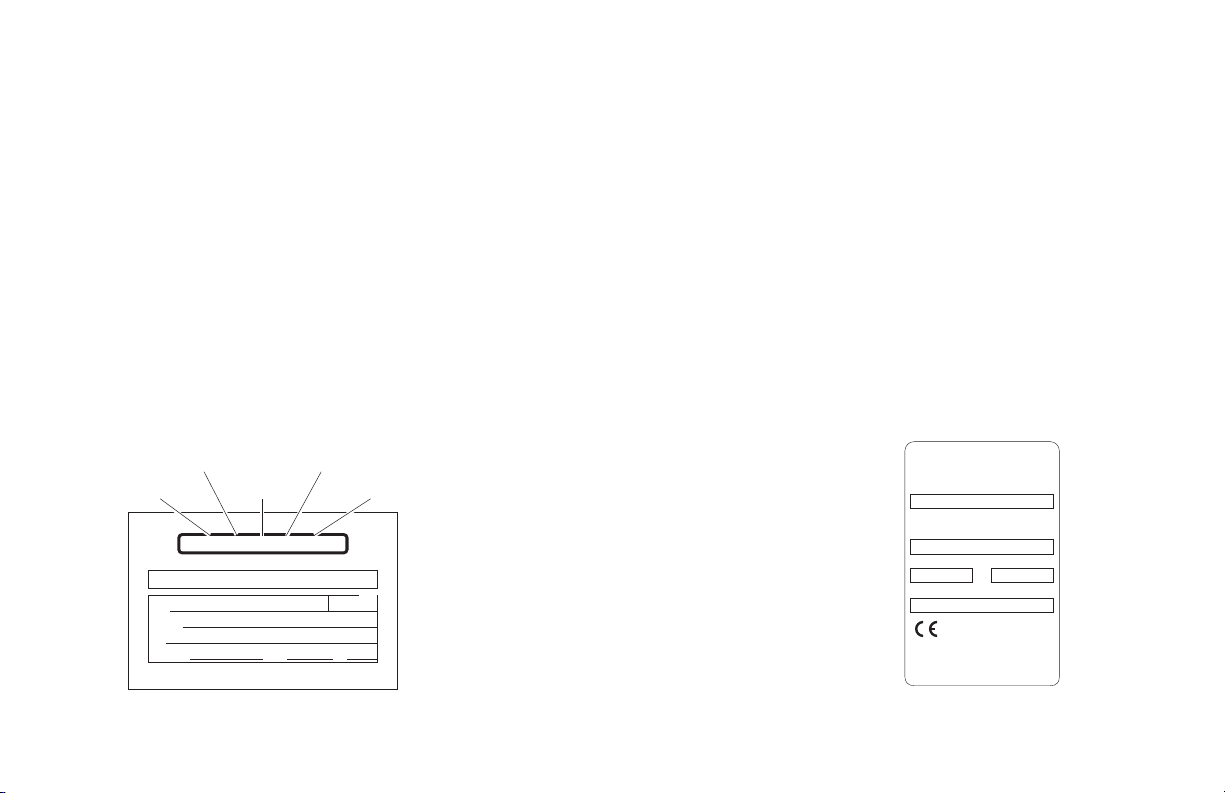
Two warranty/registration cards
(shown below) are located in
the pump cover owner's manual
storage pouch. The sales representative must process one of the
FDUGV7KHFRQVXPHUPXVWÀOORXW
Series No. Pump Code
Serial No.Model No. Cylinder Code
OWNER'S WARRANTY REGISTRATION
NL917IB-04-02730-56-14CG
PURCHASED FROM
NAME
ADDRESS
CITY
TELEPHONE
REGISTRATION CARDS MUST BE RETURNED TO THE BRAUN CORPORATION.
OWNER
STATE ZIP
TO VALIDATE WARRANTY
DATE INSTALLED
the other card and mail it to The
Braun Corporation. The warranty is
provided on the back cover of this
manual. The warranty cards must
be processed to activate the warranty.
Two Braun Serial No./Series No.
LGHQWLÀFDWLRQWDJVDUHSRVWHGRQWKH
lift. One I.D. tag (shown below) is
posted on the opposite pump side
Sample
Warranty/Registration
Card
vertical arm. A second I.D. tag is
located on the opposite pump side
tower. Both I.D. tags provide the
SURGXFWLGHQWLÀFDWLRQLQIRUPDWLRQDSpearing on the Warranty/Registration
card. Record the information in the
space provided on the next page.
This information must be provid-
HGZKHQÀOLQJDZDUUDQW\FODLPRU
ordering parts.
The Braun Corporation
1-800-THE LIFT™
BRAUNLIFT.COM™
DOT Public Use Lift MODEL#
NL917IB
Max. Lifting Capacity - 800 lbs.
SERIAL NUMBER
04-02730
PUMP CODE CYLINDER
56 14CG
MFG DATE
5/8/06
Sample
Serial No./Series No.
,GHQWLÀFDWLRQ7DJ
e5*72/245*95/54*0110*00
PATENT
PENDING-
5,261,779-6,065,924-6,238,169-6,46
4,447-6,599,079-6,692,217-6,739,824
Page 2

Warranty and Registration Instructions
Model No.
Series No.
Serial No.
Pump Code
Cylinder Code
Date of Manufacture
Note: This information must
be providedZKHQÀOLQJD
warranty claim or ordering
parts. Keep for future use.
Page 3

Hand-Held
Pendant
Control
Pump
Module
Base
Plate
Bottom Parallel
Arms (2)
Rotating Pivot
Slide Arms (2)
Visual
9
1
8
2
3
DOWN
Threshold
UP
LD
FO
UN
0
2
8
2
LD
3
FO
Warning
Towers (2)
Audible
Threshold
Warning
Lift-Tite™ Latches (2)
Threshold
Warning
Plate
Top Parallel Arms (2)
Main Cylinders (2)
Unfold Assist Compression Springs (2)
Adjustable Quiet-Ride Stow Blocks (2)
Platform Lights
Opposite Pump Side Vertical Arm
Vertical Arm Covers (4)
Handrails (2)
Inner Roll Stop
Lift Terminology
Illustration
Inboard
Right
Platform Pivot Arms (2)
Pump Side Vertical Arm
Outer Barrier Cylinder
(not visible -underside of platform)
Page 4
Platform Side Plates (2)
Outer Barrier Latch
Platform
Left
Outboard
Outer Barrier
(Automatic Outboard Roll Stop)

Lift Terminology
Introduction:
Braun NL Millennium Series
lifts are ADA compliant and
comply fully with National
+LJKZD\7UDIÀF6DIHW\$GPLQLVWUDWLRQ1+76$VSHFLÀFDWLRQV
The NL is commercial oriented
(intended for operation by an
attendant).
Lift models vary per size (lift
model numbers indicate lift
dimensions). NL Series lift
models can be equipped with
left or right side pump modules
as needed. A left side pumpequipped lift model is depicted
in the Lift Terminology Illustration (NL917IB). Right side
pump lift models are a mirrored
image of rear pump models
(pump module located on opposite end of base plate).
Refer to the Lift Terminology
,OOXVWUDWLRQIRULGHQWLÀFDWLRQRI
lift components.
Lift operation procedures
are identical for all NL Series
lift models. The operating
instructions contained in this
manual and appearing on liftposted operating instructions
decals address the lift control
switches and the corresponding lift functions. Instructions are provided for manual
operation of the lift in event of
power or equipment failure.
Terminology: Become familiar with the terminology that will
be used throughout this manual. Become familiar with the
LGHQWLÀFDWLRQRIOLIWFRPSRQHQWV
and their functions. Contact
your lift sales representative or
call The Braun Corporation at
®
1-800-THE LIFT
if any of this
information is not fully understood.
Direction: The terms "left,"
"right," "inboard," and "outboard" will be used throughout
this manual to indicate direction (as viewed from outside
the vehicle looking directly at
the lift). Refer to the Lift TermiQRORJ\,OOXVWUDWLRQVIRUFODULÀFDtion of direction terms.
Page 5

Lift TerminologyLift Terminology
Lift Components
Refer to the Lift Terminology Illustration on page 4.
Pump Module: The lift-mounted
pump module consists of the hydraulic pump, the manual hand
pump, the electronic control
board and electrical components
that power the lift electric/hydraulic systems.
Hand-held Pendant Control:
The hand-held attendant's
pendant control is connected to
the pump module. The handheld pendant is equipped with
two rocker switches, (UNFOLD,
FOLD, DOWN, and UP). The
momentary switches activate the
automatic lift functions.
Lift Frame: The lift frame consists of the base plate, threshold
warning plate, towers, parallel
arms, vertical arms, platform
pivot arms and handrails. Two
main hydraulic cylinders are
housed in the parallel arms.
The electrical/hydraulic powered
lift frame components mechanically unfold, lower, raise and fold
the lift platform assembly.
Platform Assembly: The platform assembly consists of the
steel tubing frame with grating
surface upon which the wheelchair is positioned, the outer
barrier, outer barrier latch, the
inner roll stop, and the hydraulic
cylinder assembly that powers
the outer barrier.
™
Lift-Tite
Latches: The spring-
loaded latches prevent the
platform from unfolding from the
stowed position in the event of
platform drift. Further details
™
regarding Lift-Tite
latches are
provided on pages 16 and 17.
Outer Barrier: The cylinderpowered automatic outer barrier
provides a ramp for wheelchair
loading and unloading at ground
level. Photos and further details
regarding the outer barrier are
provided in the Operation Notes
section (pages 19-21).
Outer Barrier Latch: The springloaded latch locks the outer barrier in the vertical position when
the platform raises above ground
level.
Page 6

Lift Terminology
Inner Roll Stop: NL Series lift
models are equipped with an
automatic inboard roll stop that
also serves as the bridge plate.
The roll stop bridges the gap
between the lift platform and the
YHKLFOHÁRRU7KHLQQHUUROOVWRS
automatically rotates from the
horizontal position to the vertical position as the lift lowers and
raises. Further details regarding the automatic mechanical
inboard roll stop are provided on
pages 18 and 19.
Vehicle and Lift Interlocks
Braun Corporation NL917IB
Series lifts comply fully with all
NHTSA vehicle and lift interlock
VSHFLÀFDWLRQV9HKLFOHPRYHment is prohibited unless the lift
is fully stowed and the lift will
not function unless the vehicle
is parked and secured.
The NL features a visible and
audible threshold warning
system that will activate if the
threshold area is occupied
when the platform is one inch or
PRUHEHORZÁRRUOHYHO
The inner roll stop and outer
barrier sense weight to prohibit
lift operation. The lift will not
function if the inner roll stop or
the outer barrier are occupied.
The lift platform cannot be folded
(stowed) if occupied.
The inner roll stop features a
locking mechanism that prohibits the platform from lowering if
the lock does not engage. The
lift platform cannot be raised
more than 3" above ground
level unless the outer barrier is
in the vertical position and the
outer barrier latch is positively
engaged.
Page 7

Lift Terminology
Lift Actions and Functions
DEPLOY (A-C)
A. UNFOLD (Out) - Platform
Unfold: Unfold is the action
of the platform rotating out and
down from the fully-stowed
YHUWLFDOSRVLWLRQWRÁRRUOHYHO
(horizontal) position when the
UNFOLD switch is pressed.
B. DOWN - Platform Lower:
Down is the action of the platform
ORZHULQJIURPÁRRUOHYHOSRVLWLRQ
to fully-lowered (ground level)
position when the DOWN switch
is pressed.
C. DOWN - Outer Barrier
Unfold (Deploy) - When the
platform reaches the fully-low-
ered (ground) position and the
DOWN switch is continued to be
pressed, the outer barrier rotates
downward from vertical position
to ramp position.
STOW (D-F)
D. UP - Outer Barrier Fold
(Raise): When the lift is fully
lowered and the outer barrier is
in the ramp position, pressing
WKH83VZLWFKÀUVWURWDWHVWKH
outer barrier upward from ramp
position to vertical position.
E. UP - Platform Raise: Up is
the action of the platform raising
IURPJURXQGOHYHOWRÁRRUOHYHO
(fully-raised) position when the
UP switch is pressed.
F. FOLD (In) - Platform Fold:
Fold is the action of the platform
URWDWLQJXSDQGLQIURPWKHÁRRU
level (horizontal) position to fullystowed (vertical) position when
the FOLD switch is pressed.
Stowed Position: The lift is
stowed when the lift platform has
been fully raised and folded fully
(vertical position).
Floor Level: Floor level is the
position (height) the platform assembly reaches in order for the
wheelchair passenger to enter
and exit the vehicle (fully raised).
The platform automatically stops
DWÁRRUOHYHOZKHQXQIROGLQJIURP
the stowed position and when
raising from ground level.
Page 8
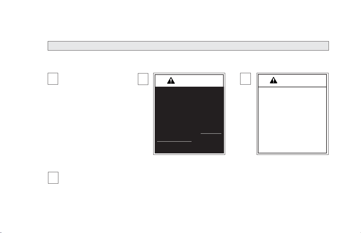
Safety Symbols
SAFETY FIRST! Know That....
Lift Operation Safety
All information contained
A
in this manual and
supplements (if included), is provided for your safety. Familiarity
with proper operation instructions
as well as proper maintenance
procedures are necessary to ensure safe, troublefree operation.
Safety precautions are provided
to identify potentially hazardous
situations and provide instruction
on how to avoid them.
Note:$GGLWLRQDOLQIRUPDWLRQSURYLGHGWRKHOSFODULI\RUGHWDLODVSHFLÀFVXEMHFW
D
These symbols will appear throughout this manual as well as on the labels posted on your lift. Recognize
the seriousness of this information.
B
This symbol indicates
important safety
information regarding
a potentially hazardous situation that
could result in serious
bodily injury and/or
property damage.
W
A
RNING
C
CAUTION
This symbol indicates
important information
regarding how to
avoid a hazardous
situation that could
result in minor personal injury or property damage.
Page 9
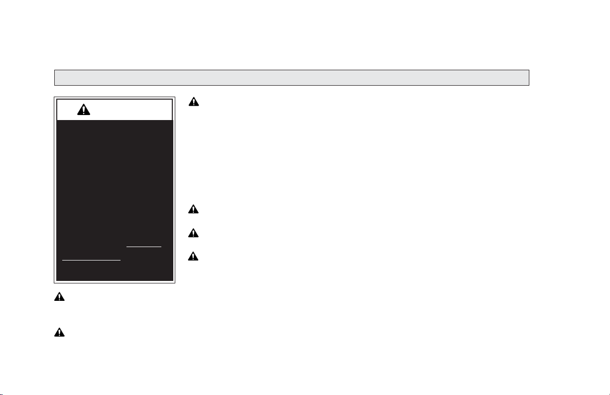
Lift Operation Safety Precautions
Lift Operation Safety
A
RNING
W
If the lift operating
instructions, manual
operating instructions
and/or lift operation
safety precautions are
not fully understood,
contact The Braun
Corporation immediately. Failure to do so
may result in serious
bodily injury and/or
property damage.
W
W
Page 10
A
RNING
A
RNING
Inspect lift before operation. Do not operate lift if you suspect lift damage, wear or any
abnormal condition.
Keep operator and bystanders clear of area in which the lift operates.
W
W
W
W
A
A
A
A
RNING
RNING
RNING
RNING
Read manual and supplement(s) before operating lift. Read
and become familiar with all safety precautions, operation
notes and details, operating instructions and manual operating instructions before operating the lift. Note: Wheelchair
passengers and all transit agency personnel (drivers and
wheelchair lift attendants) must read and become familiar
with the contents of this manual and supplement(s) before
operation.
Load and unload on level surface only.
Engage vehicle parking brake before operating lift.
Provide adequate clearance outside the vehicle to accommodate the lift before opening lift door(s) or operating lift.

Lift Operation Safety
W
W
W
W
W
W
W
W
A
A
A
A
A
A
A
A
RNING
RNING
RNING
RNING
RNING
RNING
RNING
RNING
Whenever a wheelchair passenger (or standee) is on the platform, the:
• Passenger must be positioned fully inside yellow boundaries
• Wheelchair brakes must be locked
• Inner roll stop and outer barrier must be up (vertical)
• Outer barrier latch must be fully engaged
• Passenger should grip both handrails (if able).
/RDGDQGXQORDGFOHDURIYHKLFXODUWUDIÀF
Do not overload or abuse. The load rating applies to both the raising and lowering functions - continuous lifting capacity is 800 lbs.
Discontinue lift use immediately if any lift or vehicle interlock does not operate properly.
Do not operate or board the lift if you or your lift operator are intoxicated.
Do not raise front wheelchair wheels (pull wheelie) when loading (boarding) the platform.
Open lift door(s) fully and secure before operating lift.
Position and secure (buckle, engage, fasten, etc.) the wheelchair-equipped occupant
seat belt (torso restraint) before loading onto the wheelchair lift platform.
Page 11
Lift Operation Safety
Lift Operation Safety Precautions (continued)
A
RNING
W
If the lift operating
instructions, manual
operating instructions
and/or lift operation
safety precautions are
not fully understood,
contact The Braun
Corporation immediately. Failure to do so
may result in serious
bodily injury and/or
property damage.
A
RNING
W
Page 12
Outer barrier must be fully unfolded (ramp position) until front and rear wheelchair wheels
cross the barrier when loading or unloading at ground level.
W
W
W
W
W
A
A
A
A
A
RNING
RNING
RNING
RNING
RNING
Lift attendants must ensure that lift occupants keep hands,
arms and all other body parts within the lift occupant area
and clear of moving parts.
3ODWIRUPPXVWEHSRVLWLRQHGDWÁRRUOHYHOUROOVWRSKHLJKW
when loading or unloading in and out of vehicle.
Do not use platform inner roll stop or outer barrier as a
brake. Stop and brake wheelchair when loading onto the
platform (manually stop and brake manual wheelchairs
— stop powered wheelchairs with the wheelchair controls).
Turn powered (electric) wheelchairs off when on lift platform.
Press the DOWN switch until the entire platform rests on
ground level (lowered fully) and the outer barrier is fully
unfolded (ramp position) before loading or unloading a passenger at ground level.

Lift Operation Safety
W
W
W
W
W
W
W
W
W
A
A
A
A
A
A
A
A
A
RNING
RNING
RNING
RNING
RNING
RNING
RNING
RNING
RNING
Accidental activation of control switch(es) may cause unintended operation(s).
0DLQWHQDQFHDQGOXEULFDWLRQSURFHGXUHVPXVWEHSHUIRUPHGDVVSHFLÀHGLQWKLVPDQXDOE\
DXWKRUL]HGFHUWLÀHGVHUYLFHSHUVRQQHO
Replace missing, worn or illegible decals.
Keep owner’s (operator's) manual in lift-mounted manual storage pouch at all times.
Never modify (alter) a Braun Corporation lift.
Do not use accessory devices not authorized by The Braun Corporation.
Do not remove any guards or covers.
Keep clear of any hydraulic leak.
Failure to follow these safety precautions may result in serious bodily injury and/or property damage.
Page 13

Operation Notes and Details
A
RNING
W
Read and become
familiar with all lift
operation safety
precautions, operation notes and details,
operating instructions
and manual operating instructions prior
to operating the lift.
If this information is
not fully understood,
contact The Braun
Corporation immediately. Failure to do so
may result in serious
bodily injury and/or
property damage.
NL Series “Public Use” lift models
DUHVSHFLÀFDOO\GHVLJQHGWREH
operated by an attendant. The Lift
Operating Instructions contained
in this manual and posted on the
lift provide instructions for operation of the lift only. Read and
become familiar with all lift operation safety precautions, operation notes and details, operating
instructions and manual operating
instructions before attempting lift
operation procedures.
Lift Access Doors and Interlocks: Attendants must become
familiar with the vehicle lift access
door system and vehicle interlock
system(s). Transit vehicles and
OLIWDFFHVVGRRUFRQÀJXUDWLRQV
vary. Door securement devices
(latches, hooks, cables, etc.) and
procedures to operate them vary.
Instructions for operation of
vehicle interlocks and door
securement systems are not
addressed in this manual or on
lift-posted operating instructions
decals due to the variety of procedures required for operating them.
Braun Corporation NL Series
lifts comply fully with all NHTSA
YHKLFOHDQGOLIWLQWHUORFNVSHFLÀFDtions (detailed on pages 7 and 32).
Infringement of any lift interlock
will prohibit lift operation.
It is the responsibility of the lift
operator (attendant) to properly
open, secure and close the vehicle
lift door(s), to activate the vehicle
interlock(s), to load and unload the
wheelchair passenger (or standee)
on and off the lift platform, and to
properly activate all lift functions.
Page 14
 Loading...