

Page 1
Stimuplex® HNS 11
Nerve Stimulator for
Regional Anaesthesia,
Regional Analgesia, Neurology
User manual
Page 2

Manufacturer:
Stockert GmbH
Bötzinger Straße 72
D-79111 Freiburg
Germany
Distributor:
B. Braun Melsungen AG
P.O. Box 11 20
D-34209 Melsungen
Tel. (0 56 61) 71-0
Fax (0 56 61) 71-3811
Page 3

Contents Page
Checks before start-up................................................................................................................................................ 4
Technical description..................................................................................................................................................... 6
Operating the nerve stimulator.......................................................................................................................... 7
Switching on / switching off .................................................................................................................................................. 7
Selecting the pulse frequency ............................................................................................................................................... 7
Selecting the pulse width ........................................................................................................................................................ 7
Selecting the current range .................................................................................................................................................... 8
Checking the battery voltage ................................................................................................................................................. 8
Selecting the current display mode .................................................................................................................................... 8
The LED displays.................................................................................................................................................................. 9
Current display mode ................................................................................................................................................................. 9
Current adjustment range ....................................................................................................................................................... 9
Pulse width ...................................................................................................................................................................................... 9
Pulse frequency ............................................................................................................................................................................. 9
Pulse LED display .......................................................................................................................................................................... 10
The LCD display.................................................................................................................................................................... 10
The tone........................................................................................................................................................................................11
Initial set up, maintenance and general advice.................................................................................11
Testing the Stimuplex
Special technical features ....................................................................................................................................................... 12
Technical data ................................................................................................................................................................................ 12
Battery ...............................................................................................................................................................................................13
Cleaning and disinfecting the Stimuplex
Maintenance and safety checks ...........................................................................................................................................14
Safety checks / Local law restricts ..........................................................................................................................15
Caution, Notice ............................................................................................................................................................................. 16
Safety information ...................................................................................................................................................................... 17
Error messages ............................................................................................................................................................................... 17
Instruments and accessories ..................................................................................................................................................18
®
HNS 11 before an application ...............................................................................................11
®
HNS 11 ...................................................................................................... 14
Stimuplex® HNS 11 and Accessories, Stimuplex® and Contiplex® needles............. 18
Peripheral electrical nerve stimulation...................................................................................................... 20
Performing PNS with the Stimuplex® HNS 11 and the Stimuplex® needles........ 21
Literature.................................................................................................................................................................................... 23
Appendices A to D ............................................................................................................................................................ 24
Page 4
Checks before start-up
The Stimuplex® HNS 11 is a class lla medical device according to
Council Directive 93/42/EEC. An item of medical equipment may
only be put into operation after the supplier has subjected the
equipment to a function test on site and has instructed the
person responsible for operating the equipment in the use of the
equipment with the aid of the user manual.
®
Before putting the Stimuplex
following tests.
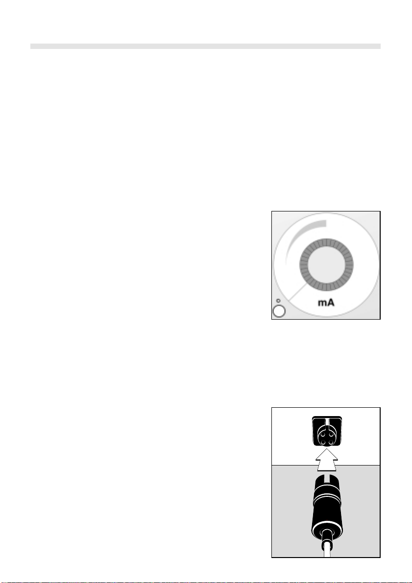
1. Turn the control knob clockwise out of the O position to switch
on the Stimuplex® HNS 11.
A brief click signals that this has taken place. At this instant, the
devices automatically starts a self-test. This includes switching
on all segments of the LCD display as a visual check.
When the self-test is completed, the stimulator immediately
switches to its normal operating mode. The LEDs on the button
panel indicate the operating conditions selected. To conserve
power, these extinguish after 8 seconds.
If no display appears when the Stimuplex
on, change the battery immediately. (Refer to the ”Battery”
section, p. 13).
If the self-test detects a defective function, the corresponding
error code will appear in the LCD display and the instrument
will then be inoperative! (Refer to the ”Error messages” section).
When the LEDs are switched off, they can be reactivated by pressing any button. This does not change the existing operating mode.
The operating mode can only be changed when the LEDs are lit.
HNS 11 into operation, carry out the
®
HNS 11 is switched
4
2. Carry out a visual inspection of the electrode cable. Damaged
cables must not be used.
Connect the electrode cable to the front of the nerve stimulator. The plug connector configuration prevents wrong polarity
connection.
Page 5
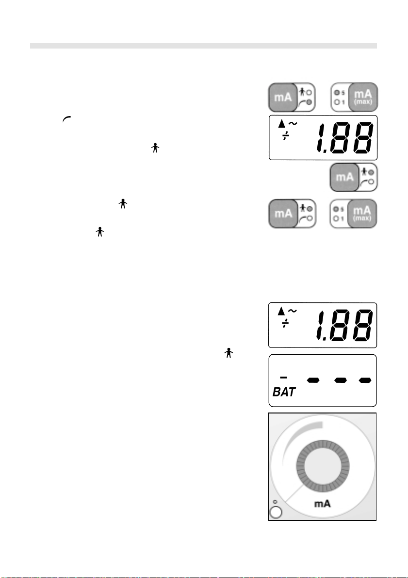
In the operating mode, the LCD display shows the preselected
stimulation current set on the controller between 0.00 and
approx. 1.00 mA (in the 1 mA range) or from 0.00 to approx.
5.00 (in the 5 mA range). In the operating mode, the Stimuplex® HNS 11 shows the stimulation current actually flowing
via the stimulation electrodes through the tissue. A ”+” sign on
the LCD display signals this setting. The operating mode is
switched by pressing the ”mA” button.
3. Select operating mode . Set the controller to 5 mA max. and
try to get a connection with the insulated, black 2 mm male plug
with a part of the red clamp. Compare – by briefly switching to
operating mode – the measured value with the set value (actual value and set value). These two values must be the same –
with shorted cables. Reset to 1 mA max. and compare these two
values (see Measuring Accuracy in Appendix A, if neccessary).
symbol appears next to the ▲ symbol in the LCD display
A
~
(Display) and the pulsed LED display (orange light-emitting diode) blinks according to the stimulation frequence.
A "+" sign appears
When a current is set at
mA, when 1 mA max. is set, and at 0.10 mA when 5 mA max. is
set.
in front of each measurement displayed.
O, the
orange LED starts to blink at 0.02
5
4. When the stimulation cable is disconnected (when is set),
+0.00 appears in the display and the ~ symbol disappears. The
pulsed LED display is no longer lit.
If the "BAT" symbol appears in the display, then the battery
voltage is getting too low. Current application can be completed without a problem, but exchanging the battery afterwards
should be considered. Press the "BAT" button to display the remaining battery voltage (in volts).
When the battery voltage is approx. 6 volts, three horizontal
dashes preceded by the "+" sign (or four dashes) appear in the
display in addition to the "BAT" symbol. In this case, the stimulator shuts off automatically.
To avoid having to abort a stimulator treatment, you should
replace the 9 volt block battery as soon as the battery voltage drops to 6.5 volts.
5. To switch off the nerve stimulator, turn the control knob anticlockwise to position O.
To conserve the battery always switch off the Stimuplex® HNS 11
after use. If you do not use it for a long period of time, remove
the battery to prevent battery leakage.
Page 6
Technical description
6. Refer to the Safety information section before using the Stimu-
plex® HNS 11 on a patient.
Any instrument behaving abnormally must not be put into
operation. Contact customer service.
Electromedical equipment may only be repaired by the manu-
facturer or by an organization expressly authorized by the manufacturer.
The Stimuplex
identification and location of nerves for local anaesthesia.
It generates consistent square pulses with selectable frequency,
selectable pulse width and continuously adjustable stimulation
current.
The range of adjustment of the pulse current from 0 to 5 mA peakto-peak can be reduced to 0 to 1 mA with the ”mA(max)” button.
This 1 mA range allows precise adjustments for extremely thin and
technically sophisticated needles.
®
HNS 11 nerve stimulator is designed for reliable
6
The stimulation frequency and the pulse width can be varied for
different applications. The Stimuplex
®
HNS 11 nerve stimulator
offers the facility for selecting a frequency of either 1 Hz or 2 Hz
can be chosen together with pulse widths of 0.1 ms, 0.3 ms or
1.0 ms.
®
When the Stimuplex
HNS 11 is switched off, all set parameters
remain stored.
As a visual and audible check, the ▲ symbol and a tick occur in
time with the stimulation. Stimulation current flowing through the
electrodes is signalled by the
in front of the value for current in the display (in operating
symbol next to the ▲ and a + sign
~
mode ).
To conserve battery power, the LEDs on the button panel for the
operating modes are switched off after approx. 8 seconds. They
are reactivated by pressing any button. This does not change the
operating mode setting, which can only be changed when the LEDs
are lit.
Page 7
Operating the nerve stimulator
Switching on / switching off
Turn the control knob clockwise out of the O position to switch on
the Stimuplex® HNS 11. A brief click signals that this has taken
place. At this instant, the device automatically starts a self-test.
This includes switching on all segments of the LCD display as a
visual check. When the self-test is completed, the nerve stimulator
immediately switches to its normal operating mode. The LEDs on
the button panel indicate the operating conditions selected (see
below). To conserve power, these extinguish after 8 seconds. They
light up again immediately when a button is pressed, but this does
not change the operating mode. The operating mode can only be
changed when the displays are lit.
To switch off the nerve stimulator, turn the control knob
anticlockwise to position O.
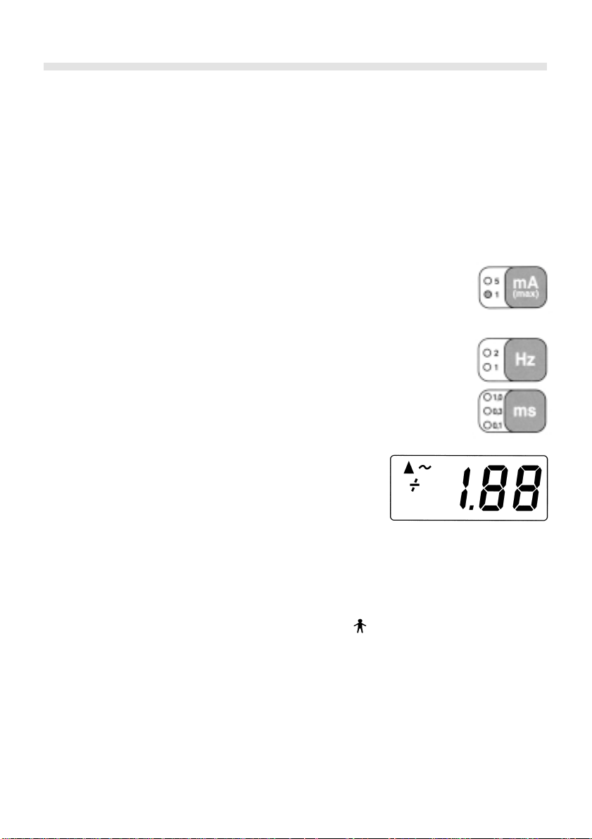
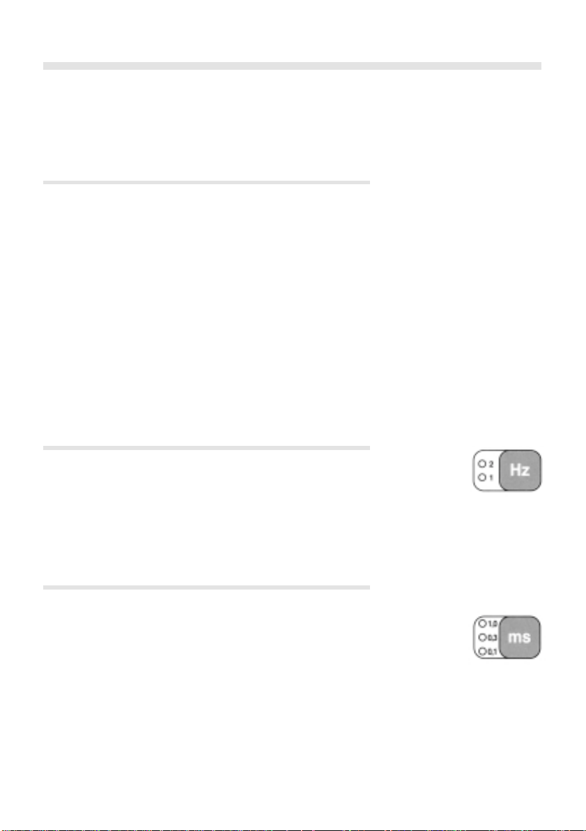
Selecting the pulse frequency
7
The selected setting is displayed and stored. You can change the
setting by pressing the "Hz" button when the LED display is lit. The
Stimuplex
®
HNS 11 nerve stimulator offers the facility of selecting
a frequency of 1 Hz or 2 Hz (one or two pulses per second).
Selecting the pulse width
The pulse width can be set by pressing the ”ms” button. It is possible
to set a stimulation of 0.1 ms, 0.3 ms or 1.0 ms.
The selected setting is displayed and stored. Setting can be changed
by pressing the "ms" button when the LED display is lit.
Page 8
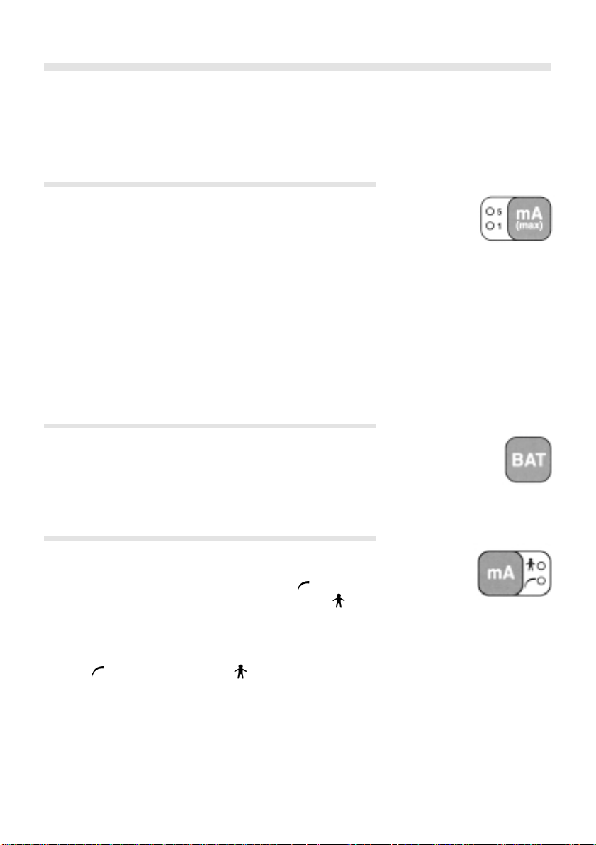
Selecting the current range
8
The maximum current available can be selected by pressing the
”mA (max)” button. The Stimuplex
®
HNS 11 nerve stimulator offers
a choice between a range up to 5 mA max. or up to 1 mA max.
Values between 0.00 mA and 1.00 mA can be selected in the 1 mA
range with the on/off control knob. This also allows precise adjustments to be made for extremely thin and technically sophisticated
needles. For safety reasons, while a patient current is flowing, it is
not possible to switch from the 1 mA range to the 5 mA range. If
this is required, turn the control to 0.00 mA and then switch over.
The selected current range is displayed and is stored until the ”mA
(max)” button is pressed again.
Checking the battery voltage
Pressing the ”BAT” button will display the existing battery voltage
on the LCD display. Pressing this button does not affect the Stimu-
®
HNS 11 functions. All settings remain unchanged.
plex
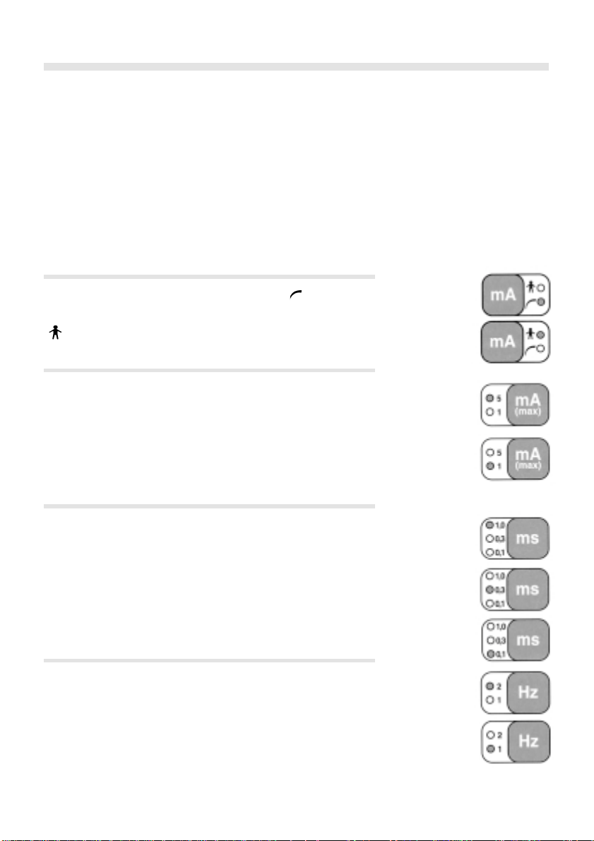
Selecting the current display mode
During operation of the nerve stimulator, the stimulation current is
shown on the LCD display. Pressing the ”mA” button selects the current display mode: the stimulation current set (mA
current) or the current actually flowing in the tissue (mA
) (displays set
) (dis-
plays actual current). In addition, a ”+” appears in front of the current on the LCD display in the case of the actual current display.
If a current display mode is set (check this by switching to operating mode
) in the operating mode mA (actual current) and +0.00
appears in the display, then the possible source of the error could be:
- the electrode cable is not connected to the device,
- the adhesive electrode is defective (possible too dry),
- the tissue resistance is very high,
- the connecting cables are defective.
The measuring mode selected is displayed and is stored until the
”mA” button is pressed again.
Page 9
The LED displays
All LEDs directly assigned to the buttons are used to monitor the
selected operating mode. Since LEDs require relatively high power,
the Stimuplex
Section 7).
The individual displays have the following significance:
Current display mode
The LCD display shows the stimulation current set ( ).
The LCD display shows the stimulation current actually flowing
). In addition, a ”+” appears in front of the current displayed.
(
Current adjustment range
Setting range from 0.00 to 5.00 mA:
Use the controller to dial a stimulation current up to 5 mA. The
current is displayed in 0.02 mA digits.
Setting range from 0.00 to 1.00 mA:
Use the controller to dial a stimulation current up to 5 mA. The
current is displayed in 0.01 mA digits.
®
HNS 11 switches them off after 8 seconds (see p. 6
9
Pulse width
Pulse width 1.0 ms: duration of stimulation pulse is 1.0 ms.
Pulse width 0.3 ms: duration of stimulation pulse is 0.3 ms.
Pulse width 0.1 ms: duration of stimulation pulse is 0.1 ms.
Pulse frequency
Pulse frequency 2 Hz (two pulses per second)
Pulse frequency 1 Hz (one pulse per second)
Page 10

Pulse LED display
The small orange LED above the LCD display flashes according to
the pulse frequency set (1 Hz: once per second; 2 Hz: twice per
second) when current is flowing through the electrodes. At the
same time, a louder tick can be heard.
The LCD display
According to the display mode selected, the LCD display shows the
setting for, or the actually flowing stimulation current. The display
is in mA.
▲
symbol indicates the stimulation frequence. At the same time,
The
there is a ticking sound in the same stimulation frequence. A
symbol appears next to the ~ symbol in the same stimulation
frequence when the stimulation current is flowing and the ticking
sound gets louder. When the actual value display is selected, the
LCD display additionally shows a "+" in front of the current displayed.
▲
10
Exceptions:
1. Pressing the ”BAT” button displays the battery voltage.
2. Equipment-related error functions produce the corresponding
error code in the display (see p. 17).
3. The ”BAT” symbol in the display indicates that the battery must
be exchanged soon.
4. When the battery voltage drops to approx. 6 volts
or
appears on the display. The stimulator switches off automatically
when these signs appear.
Display:
The ”BAT” symbol indicates that the battery voltage is too low.
(Refer to the ”Battery” section, p. 13)
Page 11

The tone
Each generated pulse produces a tick. When a stimulation current
flows to the electrodes (greater than 2% of the maximum stimula-
tion adjustable), the tick becomes louder.
If the stimulation current flowing exceeds the current set, then
taking into account the measuring tolerance (see page 12 - Techni
cal data - Measuring tolerance), the Stimuplex® HNS 11 institutes
an error message consisting of several tone groups of rapid
frequency (approx. 6 Hz). The device is no longer operational.
Each time a button is pressed a short tone is produced of a different frequency as audible confirmation.
A click confirms that the instrument has been switched on.
Initial set up, maintenance, and general advice
Testing the Stimuplex® HNS 11 before an application
Switch on the Stimuplex
control knob clockwise from position O. A short click confirms that
switching on has taken place. When the self-test has been completed, the unit changes over immediately to the normal operating
mode. You can now select the frequency, pulse width and current
range according to the application required (see Section ”Operating the nerve stimulator”, p. 7).
With the set current indication (mA
trodes - check both current ranges (1 mA max and 5 mA max) up
to maximum.
Switch to actual current indication (mA
a should reading of + 0.00 mA, independet from the set current.
Connect the two electrodes (clip and plug) together: check the mA
value in each case up to the maximum. All mA values have a ”
sign in front of the display. As soon as current flows, the LED above
the display flashes in time with the stimulation current. The
symbol appears next to the
Set an actual current of approx. 0.30 mA and switch to set current
): the two values should be the same (see Page 12 - Techni-
(mA
cal data - Measuring tolerance).
If all adjustments have been found to be correct, your Stimuplex
HNS 11 is ready for application.
®
HNS 11 nerve stimulator by turning the
), do not connect both elec-
) - both mA ranges give
▲
and the tick becomes louder.
+
~
11
-
”
®
Page 12

Special technical features
The configuration of the electrode connection provides protection
against a wrong polarity connection of the electrode cable.
This new type of plug connection system ensures correct polarity
of the electrodes at all times.
A high stimulation voltage is associated with an unusually wide
range of adjustment with extremely small stimulation electrodes.
®
The Stimuplex
HNS 11 generates a negative, current-stabilized
square pulse. In contrast to conventional instruments of this type,
the pulse is shaped at both slopes by extremely fast active pulse
drivers. An output amplifier specially designed for this application
has an extraordinarily wide dynamic range and produces reproducible settings even below 0.1 mA.
Use of the latest microcomputer technology has made it possible
to integrate performance characteristics which until now could
only be provided in large systems. For example: selection of current display mode, set and actual value display, display of battery
charge, error messages.
An internal quartz time base ensures precise pulse widths and
frequencies.
12
Technical data
Type: Stimuplex
®
HNS 11 nerve stimulator
Instrument type ................ BF
Battery ................................. 9 V
Power consumption.........3.3 mA
Stimulation current ......... max. 5 mApp / 0 ⏲ - 12 k⏲
Stimulation voltage ........ max. 65 Vpp
Stimulation frequency .... 1 Hz / 2 Hz
Measuring tolerance ....... Adjustment control display =3% (set point)
Flowing current display = 2% (actual value)
based on set mA max values (5 mA or 1 mA)
Weight ................................. 250 g
Due to its high maximum output voltage the nerve stimulator covers a wide range of skin and needle impedance. This is especially
important when using stimulation needles with an extremely small
conductive area (pin point electrode tip) such as Stimuplex
Contiplex
®
D needles.
®
D and
Page 13

Battery
The battery must be regularly checked for correct charge by pressing the ”BAT” button. While the button is pressed, the existing
battery voltage appears on the LCD display. The battery should be
replaced under 7 volts – as soon as the BAT symbol appears.
When the battery voltage drops below 6 V, the nerve stimulator
stops operating. Four horizontal lines and the BAT symbol appear
in the LCD display. Change the battery.
®
When the Stimuplex
HNS 11 nerve stimulator is not used for a
long period of time, the battery must be removed to prevent leakage.
Changing the battery
The battery compartment is in the base of the nerve stimulator.
Open the compartment by lightly pressing the OPEN symbol. At
the same time, slide the cover in the direction of the arrow.
13
Change the battery, ensuring correct polarity. After fitting the battery, slide the cover of the battery compartment back on again
right up to the limit stop.
Use only 9 V alkaline manganese batteries (e.g. VARTA 4022,
DURACELL MN 1604). These will provide you with a greatly
extended operating time and thus considerably more reliable
function.
Warning!
If the battery is leaking, the Stimuplex® HNS 11 should no longer
be operated for safety reasons. Acid penetrating the inside of the
instrument can damage or impair essential circuitry. It must be
returned to the manufacturer for correct cleaning and a safety check.
Page 14

Cleaning and disinfecting the Stimuplex® HNS 11
14
Use only soft, damp cloths to clean and disinfect the Stimuplex
HNS 11 and the electrode cable. Water, soap or white spirits are
especially suitable for this. Ensure that no moisture penetrates the
Stimuplex
®
HNS 11.
Use only wet disinfection, no spray disinfection! Avoid
condensation!
White spirit or commercially available methanol-free disinfectant
in an ethyl alcohol base can be used for disinfection.
Caution!
The following substances must not be used:
trichloroethylene, acetone, methyl ethyl ketone, benzene, methanol, cellulose thinner, 1-propanol and 2-propanol.
Maintenance and safety checks
®
Check the serviceable condition of the Stimuplex
cessories on each occasion before use. A defective instrument must
not be used.
Electromedical equipment may only be repaired by the manufacturer or by an organization expressly authorized by the manufacturer. An order for repairs must be accompanied by a detailed
description of the fault (acc. separate Technical Service Manual).
HNS 11 and ac-
®
Page 15

For usage of HNS 11 please refer to the individual local law
restricts (eg. maintaining a logbook, etc.).
In case of conducting safety checks on the device, please refer
to the enclosed inspection sheet.
15
Page 16

Caution
Electromagnetic fields may interfere with the function of the nerve
stimulator. Do not use the stimulator in the proximity of equipment which produces strong electromagnetic fields such as HF
high frequency surgical equipment, micro wave equipment or cordless phones.
Notice
®
The cables of the nerve stimulator Stimuplex
HNS 11 should be
positioned in such a way that they do not contact either the
patient or other cables.
All accessories have to be visually inspected at regular time intervals. The insulation of the cables must not exhibit any damage.
Only original accessories from B. Braun labelled with the CE sign
should be used.
16
Regarding the disposal of the nerve stimulator and its accessories
you should refer to the corresponding regulations in your country.
Storage and shipping conditions:
0 – 50° C, up to 90 % relative humidity, non condensation.
Warranty
Stimuplex
®
HNS 11 is guaranteed for two years against defects
in material and workmanship if the device is used in accordance
with the operationg instructions.
Wear and tear parts such as electrode cables, batteries, etc. are not
covered by this warranty. In addition, relevant sections of our
General Sales Conditions (Allgemeine Verkaufsbedingungen) apply
particularly in chapter IV No. 8.
Page 17

Safety information
The nerve stimulator should not be used on patients with
implanted electrical devices (e.g. cardiac pacemakers) without
prior consultation with an appropriate medical specialist. Possible
interference with the implanted devices by the stimulation current
could represent a danger to the patient.
The adhesive electrodes must not be applied in the area of injuries.
The Stimuplex® HNS 11 nerve stimulator must not be used in areas
where there is an explosion hazard.
The Stimuplex
®
HNS 11 nerve stimulator must not be used close to
microwave therapy equipment. The possible pick-up of radio
frequency currents by the stimulation electrode could damage the
nerves.
The patient current should not drop below a specific value (please
refer to p. 21 points 8 and 9).
17
®
If the battery has leaked, the Stimuplex
HNS 11 must not continue
to be operated for safety reasons. It must be returned to the
manufacturer for correct cleaning. The same applies if any liquid
soaks through!
In the event of warning tone sequences (tone groups of approx.
6 Hz), the Stimuplex
®
HNS 11 must be switched off and returned to
the manufacturer or distributor for repair.
Error messages
When the Stimuplex® HNS 11 nerve stimulator is switched on, it
automatically carries out a self-test. If this detects a faulty function,
the fault is shown on the corresponding error code on the LCD
display. The Stimuplex
®
HNS 11 is then no longer operational. It
must be returned to the manufacturer for repair. You should state
the error code in the repair order.
The following error codes are possible:
- F1: Analogue data acquisition is faulty
- F2: Error in the program
- F3: Reference error in the analogue data acquisition system
Page 18

Instruments and accessories
®
The Stimuplex
HNS 11 nerve stimulator should only
with the accessories and instruments mentioned
be operated
on page 13, 14,
18 and 19 of this user manual.
Check the accessories and instruments for serviceable condition
before every occasion of use and comply with the care and disinfection instructions supplied (p. 14).
Stimuplex® HNS 11 and Accessories, Stimuplex® and Contiplex® needles
Product discription Canula Code number Sales unit
Ø x length
Stimuplex® HNS 11 nerve stimulator 4892097 1
– with electrode cable for Stimuplex
Stimuplex® A- and Contiplex® D- needles
Knob for sterile handling 4892283 1
Electrode cable for Stimuplex
Stimuplex® A and Contiplex® D needles
Connection cable for Contiplex® A needles 4892925 1
Stimuplex® D needles, 15° bevel
1
D 25/035; 25 G x 1
D 25/055; 25 G x 2
D 26/040; 23 G x 1
D 26/070;
23 G x 23/4" 0.6 x 70 mm 4894138 25
/3" 0.5 x 35 mm 4894103 25
1
/8" 0.5 x 55 mm 4894111 25
1
/2" 0.6 x 40 mm 4894120 25
D 27/050; 22 G x 2" 0.7 x 50 mm 4894146 25
1
D 27/080; 22 G x 3
D 27/120; 22 G x 4
/8" 0.7 x 80 mm 4894154 25
3
/4" 0.7 x 120 mm 4894162 25
D 29/150; 20 G x 6" 0.9 x 150 mm 4894170 25
Stimuplex® D needles 30° bevel
1
D 17/040; 22 G x 1
/2" 0.7 x 40 mm 4894189 25
D 17/050; 22 G x 2" 0.7 x 50 mm 4894197 25
1
D 17/080; 22 G x 3
/8" 0.7 x 80 mm 4894200 25
®
D-,
®
D, 4892070 1
18
Page 19

Product discription Canula Code number Sales unit
Ø x length
Stimuplex® A needles, 30° bevel
A 25; 24 G x 1" 0.55 x 25 mm 4894251 25
A 25; 22 G x 1" 0.70 x 25 mm 4894539 25
A 50; 22 G x 2" 0.70 x 50 mm 4894502 25
A 50; 21 G x 2" 0.80 x 50 mm 4894375 25
A 100; 21 G x 4" 0.80 x 100 mm 4894260 25
A 150; 20 G x 6" 0.90 x 150 mm 4894278 25
Contiplex
D 28/055/C; 18 G x 2
®
D needles, 15° bevel
1
/8" 1.3 x 55 mm 4894219 25
D 28/110/C; 18 G x 43/8" 1.3 x 110 mm 4894294 25
Contiplex
®
D needles, 30° bevel
D 18/055/C; 18 G x 21/8" 1.3 x 55 mm 4894227 25
Contiplex® D Catheter Set
– with polyamide catheter
0.45 x 0.85 x 400 mm
needle D 28/055/C; 18 G; 15° bevel 1.3 x 55 mm 4894235 10
needle D 18/055/C; 18 G; 30° bevel 1.3 x 55 mm 4894243 10
– with polyamide catheter
0.45 x 0.85 x 1000 mm
needle D 28/110/C; 18 G; 15° bevel 1.3 x 55 mm 4894391 10
Contiplex
A 45/C; 18 G x 1
®
A needles, 30° bevel
3
/4" 1.3 x 45 mm 4893611 25
A 55/C; 18 G x 21/8" 1.3 x 55 mm 4893643 25
Contiplex
®
A Catheter Set
– with polyamide catheter
0.45 x 0.85 x 400 mm
needle A 45/C; 18 G; 30° bevel 1.3 x 45 mm 4893603 10
needle A 55/C; 18 G; 30° bevel 1.3 x 55 mm 4893638 10
Alphaplex
– with catheter 0.9 m x1.25 m x 330 mm,
– guide wire and Contiplex
®
Catheter Set
®
D
– D 28/055/C; 15° and 30° bevel
Basic Set, 15° bevel 1.3 x 55 mm U 1800 210 10
Super Set, 15° bevel 1.3 x 55 mm U 1800 200 10
Basic Set, 30° bevel 1.3 x 55 mm U 1800 201 10
Super Set, 30° bevel 1.3 x 55 mm U 1800 203 10
19
Page 20

Peripheral electrical nerve stimulation
Principles
By simplifying the accurate location of peripheral nerves, periph-
eral electrical nerve stimulation (PNS) facilitates the performance
of nerve and plexus blocks increasing their safety and reliability.
The old rule ”no paraesthesia - no anaesthesia” (1) loses its validity, because information from the patient concerning paraesthesia
is eliminated, and the danger of a mechanical nerve lesion (8) is
largely excluded. The principle consists of triggering depolarizations with electrical pulses at, but not within, the nerve, causing
muscular contractions at the effector muscle or sensitive sensations in the distribution area. Paraesthesia due to direct contact of
injection needles and nerve is consciously avoided.
PNS does not replace the anatomical knowledge required for regional anaesthesia, rather it assumes accurate knowledge of the
topography and the nerve distribution area.
The various types of nerve fibre differ in regard to their sensitivity
to electrical stimulation. The A-alpha motor fibres have the short-
est chronaxia (50 - 100 µs). The fibres of pain sensation (A-delta
and C-fibres) require a longer pulse (150 and 400 µs respectively)
at minimum current. Mixed peripheral nerves can be localized with
short pulses (0.1 ms) without triggering pain sensations. For pure
sensory nerves, a longer pulse (0.3 or 1.0 ms) is recommended.
When using unipolar needles (needles with an insulated needle
shaft and a conductive tip), the current necessary to trigger muscular contractions (= pulse amplitude) correlates with the distance
of the tip of the needle from the nerve: the lower the threshold
current the more accurately is the nerve localized, and the shorter
the onset and more reliable the success of the block (4). The shorter the electrical pulse (= pulse width), the faster is the rise in current to the nerve, and the clearer the discrimination as to whether
the needle tip is sufficiently close to the nerve (2,5). The stimulation needle should always be connected to the negative pole because higher currents are required if the polarity is reversed (needle positive) (6).
The geometry of the electrical current field is dependent on the
geometry of the conductive tip of the stimulation needle. The smaller the emission site of the electrons at the tip of the needle, the
higher is the current density at this point and the lower the threshold current when the nerve is exactly localized.
The Stimuplex
the most modern aspects and the requirements which originate
from the theory and practice of peripheral electrical nerve stimulation (3,6). It is provided with alarm systems necessary for the
®
HNS 11 stimulator has been designed according to
20
Page 21

early detection of technical faults which could endanger the
patient and place the success of the anaesthesia in jeopardy.
Performing PNS with the Stimuplex® HNS 11 and the Stimuplex® or Contiplex® needles
1. Check the Stimuplex® HNS 11.
2. Check the skin electrode (ECG adhesive electrode) (the conduc-
tive gel must not have dried) and apply it to a degreased area of
skin which is not in the distribution area of the nerve to be
blocked.
3. Carry out patient positioning, skin disinfection, and if neces-
sary, local infiltration of the needle puncture site.
4. Connect the electrode cables to the stimulation needle (nega-
tive) and skin electrode (positive), switch on the Stimuplex
11 and set the mA controller current (mA
) to zero.
®
HNS
After the automatic self-test of the stimulator, the ▲ symbol
appears in the display in time with the stimulation pulse to
indicate that it is ready to operate.
Caution! A change to the stored parameters can only be made
when the LEDs are lit. By pressing any button the LEDs will light up
and indicate the value stored. To change press the appropriate
button.
21
5. Select pulse width (0.1 ms, 0.3 ms or 1.0 ms).
6. Select pulse frequency (1 Hz or 2 Hz).
7. Select amplitude range (1 mA max or 5 mA max.).
®
8. Advance the Stimuplex
or Contiplex® needle through the skin
and the subcutaneous tissue towards the nerve to be blocked.
Set a current of approx. 0.30 mA (set value mA
) - the orange
LED above the display flashes in time with the stimulation, the
display shows a
next to the
~
▲
and a tick signals that current
is flowing in the tissue.
Then switch to actual current flowing value indicator (mA
and check that the actual value corresponds to the set value
(see p. 12 - Technical data, measuring tolerance).
)
Page 22

If the two values coincide, the total resistance is acceptable
(impedance test) and the electric circuit is satisfactory. If the
actual value is less than the set value, this indicates that the
electrical resistance in the external circuit is too high. The cause
must be found e.g. adhesive electrode too dry, skin resistance
too high, broken cable.
After the impedance test, leave in the mA
position (current
flowing at the tip of the needle indicated and a + sign in front
of the current displayed) until the block is successful.
9. Set an actual current of approx. 1 to 2 mA and advance the
needle further until the first muscles supplied by contractions
occur in the nerve sought. Then, while reducing the current,
advance the needle to the nerve until the recommanded threshold current. (For values see, for example, literature references
4, 7). The threshold current to be achieved depends on the pulse
width and the geometry of the conductive tip of the needle.
®
Warning! When using Stimuplex
or Contiplex® needles, it must
be noted that muscular contractions with a current of 0.2 to
0.5 mA and a stimulus duration of 0.1 ms - with a current of
0.05 to 0.2 mA and a stimulus duration of 1.0 ms - indicate
satisfactory proximity to the nerve sought. Any further reduction in the ”threshold currents” may cause direct contact of
the needle with the nerve, resulting in the danger of a mechanical nerve lesion.
22
If needles from other manufacturers are used, the threshold
currents may be much higher. You would have to work out
these yourself.
10. After clearly visible muscular contractions are seen using the
desired threshold current, inject local anaesthetic.
The response to the electrical stimulation will reduce or disappear within a few seconds after an injection of 2 - 3 ml. If this
effect is not definite, do not continue to search for the nerve
at the same location. For safety reasons, a more peripheral site
should be used.
Page 23

Literature
Literature
1. Moore DC (1965), Regional block. A handbook for use in the
clinical practice of medicine and surgery. Thomas, Springfield
II. (4th ed.)
2. Ford DJ, Pither CE, Raj PP (1984), Electrical characteristics of
peripheral nerve stimulators. Implications for nerve Iocalization. Reg Anesth 9:73.
3. Ford DJ, Pither CE, Raj PP (1984), Comparsion of insulated and
uninsulated needles for locating peripheral nerves with a peripheral nerve stimulator. Anesth. analg. 63:925
4. Kaiser H, Niesel HC, Klimpel L (1988), Einfluss der Reizstrom-
stärke der Nervestimulation auf Latenz und Erfolg der hinteren
Ischiasdiskusblockade. Regional-Anaesthesie 11:92.
5. Kaiser H, Niesel HC, Hans V (1990), Grundlagen und Anforde-
rungen der peripheren elektrischen Nervenstimulation. Regional-Anaesthesie 13:143
6. Kaiser H, Niesel HC, Hans V, Klimpel L (1990), Untersuchungen
zur Funktion peripherer Nervenstimulation für die Durchführung von Nerven- und Plexusblockaden. Regional-Anaesthesie
13:172.
7. März P, (1990), Kann bei der elektrischen Nervenstimulation
aus der Intensität der Muskelkontraktion auf den Abstand zum
Nerven geschlossen werden? Regional-Anaesthesie 13:179.
8. Selander D, Edshage S, Wolff T (1979), Paraesthesiae or no pa-
raesthesiae: nerve lesions after axillary block.
Acta anaesthesiol. scand. 23:27.
23
Further literature:
Kaiser H, Die periphere Nervenstimulation
In Niesel HC (dir.), Regionalanästhesie, Lokalanästhesie, Regionale
Schmerztherapie. Thieme-Verlag Stuttgart New York (1994), 186-207.
Prithvi Raj P (Editor), Clinical practice of regional anaesthesia.
Churchill Livingstone New York (1991)
Pinncock CA, Fischer HBJ, Jones RP, Peripheral nerve blockade.
Churchill Livingstone New York (1996)
Scott DB, Introduction to regional anaesthesia.
Mediglobe Fribourg (1989)
Page 24

Appendix A
Stimulation current display in the mA range
Patient current Measurement display Controller display
0.00 mA 0.00 mA 0.00 mA
0.05 mA 0.05 mA ± 0.02 0.05 mA ± 0.03
0.10 mA 0.10 mA ± 0.02 0.10 mA ± 0.03
0.20 mA 0.20 mA ± 0.02 0.20 mA ± 0.03
0.30 mA 0.30 mA ± 0.02 0.30 mA ± 0.03
0.40 mA 0.40 mA ± 0.02 0.40 mA ± 0.03
0.60 mA 0.60 mA ± 0.02 0.60 mA ± 0.03
0.80 mA 0.80 mA ± 0.02 0.80 mA ± 0.03
1.00 mA 1.00 mA ± 0.02 1.00 mA ± 0.03
Patient current Measurement display Controller display
0.00 mA 0.00 mA 0.00 mA
0.50 mA 0.50 mA ± 0.1 0.50 mA ± 0.15
1.00 mA 1.00 mA ± 0.1 1.00 mA ± 0.15
1.50 mA 1.50 mA ± 0.1 1.50 mA ± 0.15
2.00 mA 2.00 mA ± 0.1 2.00 mA ± 0.15
3.00 mA 3.00 mA ± 0.1 3.00 mA ± 0.15
4.00 mA 4.00 mA ± 0.1 4.00 mA ± 0.15
5.00 mA 5.00 mA ± 0.1 5.00 mA ± 0.15
Appendix B
Conversion table: Amplitude (mA) and pulse width (ms) to charge (nano-Coulomb, nC)
Amplitude Pulse width Charge Pulse width Charge Pulse width Charge
mA ms nC ms nC ms nC
0.1 0.1 10 0.3 30 1.0 100
0.2 0.1 20 0.3 60 1.0 200
0.3 0.1 30 0.3 90 1.0 300
0.4 0.1 40 0.3 120 1.0 400
0.5 0.1 50 0.3 150 1.0 500
0.6 0.1 60 0.3 180 1.0 600
0.7 0.1 70 0.3 210 1.0 700
0.8 0.1 80 0.3 240 1.0 800
0.9 0.1 90 0.3 270 1.0 900
1.0 0.1 100 0.3 300 1.0 1000
1.2 0.1 120 0.3 360 1.0 1200
1.6 0.1 160 0.3 480 1.0 1600
1.8 0.1 180 0.3 540 1.0 1800
2.0 0.1 200 0.3 600 1.0 2000
2.5 0.1 250 0.3 750 1.0 2500
3.0 0.1 300 0.3 900 1.0 3000
3.5 0.1 350 0.3 1050 1.0 3500
4.0 0.1 400 0.3 1200 1.0 4000
4.5 0.1 450 0.3 1350 1.0 4500
5.0 0.1 500 0.3 1500 1.0 5000
24
Page 25

Appendix C
Appendix C
Stimuplex® HNS 11 Nerve Stimulator
Operating range
Max. stimulation
voltage [V]
25
Operating range
Stimuplex® HNS 11 Nerve Stimulator
Max. stimulation current as a function of tissue resistance
Max. stimulation
current [mA]
Battery voltage [V]
Battery voltage [V]
Page 26

Appendix D
26
Bare and insulated needles
Stimulation current
[mA]
Distance from the nerve [mm]
Stimuplex® D and Contiplex® D needles (DP: DE 3919666)
Only 0.2 or 0.05 mA
stimulation current required
Stimulation
current
[mA]
Current density
Bare,
uncoated
needles
Coated
needles
bevel uncoated
Stimuplex
Contiplex
Fully insulated
needle with
bare tip
®
Stimuplex
Contiplex
D
®
D
Stainless
steel needle
Plastic
insulation
®
A
®
A
blunt
30°
pointed
15°
Distance from the nerve [mm]
Threshold currents down to minimum 0.05 mA (with 1.0 ms pulse width)
and minimum 0.2 mA (with 0.1 ms pulse width)
allow reliable location of nerves.
Page 27

Page 28

Caution:
Federal (U.S.A.) law restricts
this device to sale by or on the order
of physicians.
W. 01.08.01/7 Nr. 6043895
hospital care
B. Braun Melsungen AG
P.O. Box 11 20
D-34209 Melsungen
Tel (0 56 61) 71-0
Fax (0 56 61) 71-3811
www.bbraun.com
 Loading...