


100-214-251 IWoper.book Page i Friday, June 16, 2017 4:12 PM
100-214-251 - REV. 05
2000IW/IW+
Integrated Welder
Instruction Manual
Branson Ultrasonics Corporation
41 Eagle Road
Danbury, CT 06813-1961 USA
(203) 796-0400
http://www.bransonultrasonics.com

100-214-251 IWoper.book Page i Friday, June 16, 2017 4:12 PM
Manual Change Information
At Branson, we strive to maintain our position as the leader in ultrasonics plastics joining,
cleaning and related technologies by continually improving our circuits and components in
our equipment. These improvements are incorporated as soon as they are developed and
thoroughly tested.
Information concerning any improvements will be added to the appropriate technical
documentation at its next revision and printing. Therefore, when requesting service
assistance for specific units, note the Revision information found on the cover of this
document, and refer to the printing date which appears at the bottom of this page.
Copyright and Trademark Notice
Copyright © 2003 Branson Ultrasonics Corporation.
All rights reserved.
Contents of this publication may not be reproduced in any form without the written
permission of Branson Ultrasonics Corporation.
Trademarks and service marks mentioned herein are held by their respective owners.
100-214-251 REV. 05 i

100-214-251 IWoper.book Page ii Friday, June 16, 2017 4:12 PM
Foreword
Congratulations on your choice of a Branson Ultrasonics Corporation system!
The Branson 2000-Series system is process equipment for the joining of plastic parts
using ultrasonic energy. It is the newest generation of product using this sophisticated
technology for a variety of customer applications. This Instruction Manual is part of the
documentation set for this system, and should be kept with the equipment.
Thank you for choosing Branson!
Introduction
This manual is arranged into several structured chapters which will help you find the
information you may need to know to safely handle, install, set up, program, operate,
and/or maintain this product. Please refer to the Table Of Contents and/or the Index of
this manual to find the information you may be looking for. In the event you require
additional assistance or information, see Section 1.4 How to Contact Branson for
information on how to contact the appropriate Branson representative.
ii 100-214-251 REV. 05

100-214-251 IWoper.book Page iii Friday, June 16, 2017 4:12 PM
Table Of Contents
Chapter 1: Safety and Support
1.1 Safety Requirements and Warnings . . . . . . . . . . . . . . . . . . . . . . . . . . . . . . . . . . . 2
1.2 General Precautions. . . . . . . . . . . . . . . . . . . . . . . . . . . . . . . . . . . . . . . . . . . . . . 4
1.3 Warranty Statement, Disclaimer . . . . . . . . . . . . . . . . . . . . . . . . . . . . . . . . . . . . . 6
1.4 How to Contact Branson. . . . . . . . . . . . . . . . . . . . . . . . . . . . . . . . . . . . . . . . . . . 8
1.5 Returning Equipment for Repair . . . . . . . . . . . . . . . . . . . . . . . . . . . . . . . . . . . . . 9
1.6 Obtaining Replacement Parts . . . . . . . . . . . . . . . . . . . . . . . . . . . . . . . . . . . . . . .12
Chapter 2:The 2000IW/IW+ Welder
2.1 Models Covered. . . . . . . . . . . . . . . . . . . . . . . . . . . . . . . . . . . . . . . . . . . . . . . . .14
2.2 Overview of these Models. . . . . . . . . . . . . . . . . . . . . . . . . . . . . . . . . . . . . . . . . .15
2.3 Compatibility with Branson Products . . . . . . . . . . . . . . . . . . . . . . . . . . . . . . . . . .18
2.4 Features. . . . . . . . . . . . . . . . . . . . . . . . . . . . . . . . . . . . . . . . . . . . . . . . . . . . . .19
2.5 Front Panel Controls . . . . . . . . . . . . . . . . . . . . . . . . . . . . . . . . . . . . . . . . . . . . .20
2.6 Rear Panel . . . . . . . . . . . . . . . . . . . . . . . . . . . . . . . . . . . . . . . . . . . . . . . . . . . .27
2.7 System Inputs/Outputs . . . . . . . . . . . . . . . . . . . . . . . . . . . . . . . . . . . . . . . . . . .29
2.8 Glossary of Terms . . . . . . . . . . . . . . . . . . . . . . . . . . . . . . . . . . . . . . . . . . . . . . .31
Chapter 3:Delivery and Handling
3.1 Shipping and Handling . . . . . . . . . . . . . . . . . . . . . . . . . . . . . . . . . . . . . . . . . . . .34
3.2 Receiving . . . . . . . . . . . . . . . . . . . . . . . . . . . . . . . . . . . . . . . . . . . . . . . . . . . . .35
3.3 Unpacking . . . . . . . . . . . . . . . . . . . . . . . . . . . . . . . . . . . . . . . . . . . . . . . . . . . .36
3.4 Returning Equipment . . . . . . . . . . . . . . . . . . . . . . . . . . . . . . . . . . . . . . . . . . . . .37
Chapter 4: Installation and Setup
4.1 About Installation . . . . . . . . . . . . . . . . . . . . . . . . . . . . . . . . . . . . . . . . . . . . . . .40
4.2 Handling and Unpacking. . . . . . . . . . . . . . . . . . . . . . . . . . . . . . . . . . . . . . . . . . .41
4.3 Take Inventory of Small Parts. . . . . . . . . . . . . . . . . . . . . . . . . . . . . . . . . . . . . . .44
4.4 Installation Requirements. . . . . . . . . . . . . . . . . . . . . . . . . . . . . . . . . . . . . . . . . .45
4.5 Installation Steps . . . . . . . . . . . . . . . . . . . . . . . . . . . . . . . . . . . . . . . . . . . . . . .49
4.6 Accessory Input/Output Option . . . . . . . . . . . . . . . . . . . . . . . . . . . . . . . . . . . . . .60
4.7 Guards and Safety Equipment. . . . . . . . . . . . . . . . . . . . . . . . . . . . . . . . . . . . . . .61
4.8 Assemble the Acoustic Stack. . . . . . . . . . . . . . . . . . . . . . . . . . . . . . . . . . . . . . . .62
4.9 Installing the Ultrasonic Stack in the Integrated Welder . . . . . . . . . . . . . . . . . . . . .65
4.10 Adjusting Welder Height and Aligning the Horn . . . . . . . . . . . . . . . . . . . . . . . . . . .67
4.11 Adjusting the Mechanical Stop . . . . . . . . . . . . . . . . . . . . . . . . . . . . . . . . . . . . . .68
4.12 Testing the Installation . . . . . . . . . . . . . . . . . . . . . . . . . . . . . . . . . . . . . . . . . . .72
4.13 Still Need Help? or Parts? Have Questions?. . . . . . . . . . . . . . . . . . . . . . . . . . . . . .73
Chapter 5:Technical Specifications
5.1 Technical Specifications . . . . . . . . . . . . . . . . . . . . . . . . . . . . . . . . . . . . . . . . . . .76
Chapter 6:Operation
6.1 Weld Modes . . . . . . . . . . . . . . . . . . . . . . . . . . . . . . . . . . . . . . . . . . . . . . . . . . .82
6.2 Setting Weld Cycle Parameters . . . . . . . . . . . . . . . . . . . . . . . . . . . . . . . . . . . . . .92
6.3 Controlling the Front Panel Display . . . . . . . . . . . . . . . . . . . . . . . . . . . . . . . . . . .95
6.4 Setup Procedure . . . . . . . . . . . . . . . . . . . . . . . . . . . . . . . . . . . . . . . . . . . . . . . .96
6.5 Weld Cycle State Displays and Alarms . . . . . . . . . . . . . . . . . . . . . . . . . . . . . . . .100
6.6 Resetting the System. . . . . . . . . . . . . . . . . . . . . . . . . . . . . . . . . . . . . . . . . . . . 107
100-214-251 REV. 05 iii

100-214-251 IWoper.book Page iv Friday, June 16, 2017 4:12 PM
6.7 Ultrasonic Test . . . . . . . . . . . . . . . . . . . . . . . . . . . . . . . . . . . . . . . . . . . . . . . . 108
6.8 Horn Down . . . . . . . . . . . . . . . . . . . . . . . . . . . . . . . . . . . . . . . . . . . . . . . . . . 109
6.9 Converter Cooling. . . . . . . . . . . . . . . . . . . . . . . . . . . . . . . . . . . . . . . . . . . . . . 110
Chapter 7:Maintenance
7.1 IW/IW+ Preventive Maintenance . . . . . . . . . . . . . . . . . . . . . . . . . . . . . . . . . . . 112
7.2 Parts Lists . . . . . . . . . . . . . . . . . . . . . . . . . . . . . . . . . . . . . . . . . . . . . . . . . . . 116
7.3 Circuits . . . . . . . . . . . . . . . . . . . . . . . . . . . . . . . . . . . . . . . . . . . . . . . . . . . . . 117
7.4 Troubleshooting . . . . . . . . . . . . . . . . . . . . . . . . . . . . . . . . . . . . . . . . . . . . . . . 118
iv 100-214-251 REV. 05

100-214-251 IWoper.book Page v Friday, June 16, 2017 4:12 PM
List Of Figures
Chapter 1: Safety and Support
Figure 1.1 Safety Labels on the 2000IW/IW+ Integrated Welder . . . . . . . . . . . . . . . . . . . . . . 3
Figure 1.2 Safety Label on Left Door of the 2000IW/IW+ Integrated Welder . . . . . . . . . . . . . . 3
Chapter 2:The 2000IW/IW+ Welder
Figure 2.1 2000IW/IW+ Series Integrated Welder . . . . . . . . . . . . . . . . . . . . . . . . . . . . . . . .15
Figure 2.2 Front Panel Controls, IW . . . . . . . . . . . . . . . . . . . . . . . . . . . . . . . . . . . . . . . . . .20
Figure 2.3 Front Panel Displays, IW . . . . . . . . . . . . . . . . . . . . . . . . . . . . . . . . . . . . . . . . . .22
Figure 2.4 Front Panel Displays, IW+ . . . . . . . . . . . . . . . . . . . . . . . . . . . . . . . . . . . . . . . . .24
Figure 2.5 Rear Panel . . . . . . . . . . . . . . . . . . . . . . . . . . . . . . . . . . . . . . . . . . . . . . . . . . . .27
Figure 2.6 Base, Showing START SWITCHES and Base Cable . . . . . . . . . . . . . . . . . . . . . . . . .29
Chapter 3:Delivery and Handling
Chapter 4: Installation and Setup
Figure 4.1 Unpacking the Stand (2000IW/IW+ on a Base); right-side view of Stand. . . . . . . . .41
Figure 4.2 Unpacking the Stand (2000IW/IW+ on a Hub); Hub shown separately . . . . . . . . . .42
Figure 4.3 Ultrasonic Converter (J-Type for stand use) and Booster . . . . . . . . . . . . . . . . . . . .43
Figure 4.4 2000IW/IW+ Integrated Welder Dimensional Drawing. . . . . . . . . . . . . . . . . . . . . .46
Figure 4.5 Hooking Up the Air Line . . . . . . . . . . . . . . . . . . . . . . . . . . . . . . . . . . . . . . . . . . .48
Figure 4.6 Base Mounting Centers . . . . . . . . . . . . . . . . . . . . . . . . . . . . . . . . . . . . . . . . . . .50
Figure 4.7 Mounting Bolt Pattern for the Hub (for Stand on Hub) . . . . . . . . . . . . . . . . . . . . . .51
Figure 4.8 Start Switch Connection Codes . . . . . . . . . . . . . . . . . . . . . . . . . . . . . . . . . . . . . .52
Figure 4.9 Input/Output Signals, IW/IW+ . . . . . . . . . . . . . . . . . . . . . . . . . . . . . . . . . . . . . .54
Figure 4.10 Operating Cycle Timing Table, 2000IW. . . . . . . . . . . . . . . . . . . . . . . . . . . . . . . . .55
Figure 4.11 Operating Cycle Timing Table, 2000IW+ . . . . . . . . . . . . . . . . . . . . . . . . . . . . . . .55
Figure 4.12 Moving Jumpers . . . . . . . . . . . . . . . . . . . . . . . . . . . . . . . . . . . . . . . . . . . . . . . .56
Figure 4.13 International Harmonized Line Cord Color Code . . . . . . . . . . . . . . . . . . . . . . . . . .56
Figure 4.14 Type 1 DIP Switch Marked “OPEN” on Top of Switch, Default Settings. . . . . . . . . . .57
Figure 4.15 Type 2 DIP Switch Marked “ON” on face of Switch, Default Settings. . . . . . . . . . . . .58
Figure 4.16 Accessory Input/Output Connector Pinout . . . . . . . . . . . . . . . . . . . . . . . . . . . . . .60
Figure 4.17 Integrated Welder Emergency Stop Button. . . . . . . . . . . . . . . . . . . . . . . . . . . . . .61
Figure 4.18 Assembling the 20kHz Acoustic Stack, Rectangular Horn . . . . . . . . . . . . . . . . . . . .63
Figure 4.19 Assembling the 20kHz Acoustic Stack, Cylindrical Horn . . . . . . . . . . . . . . . . . . . . .63
Figure 4.20 Connecting Tip to Horn . . . . . . . . . . . . . . . . . . . . . . . . . . . . . . . . . . . . . . . . . . .64
Figure 4.21 Installing a 20kHz Stack in a Branson Welder . . . . . . . . . . . . . . . . . . . . . . . . . . . .65
Figure 4.22 Mounting Circles on Base . . . . . . . . . . . . . . . . . . . . . . . . . . . . . . . . . . . . . . . . . .66
Figure 4.23 Adjusting the Mechanical Stop . . . . . . . . . . . . . . . . . . . . . . . . . . . . . . . . . . . . . .68
Figure 4.24 DIP Switch Location. . . . . . . . . . . . . . . . . . . . . . . . . . . . . . . . . . . . . . . . . . . . . .69
Figure 4.25 Normal Front Panel Display after Power -Up, IW (left), IW+ (right) . . . . . . . . . . . . .72
Chapter 5:Technical Specifications
Figure 5.1 CJ 20 Converter . . . . . . . . . . . . . . . . . . . . . . . . . . . . . . . . . . . . . . . . . . . . . . . .78
Chapter 6:Operation
Figure 6.1 Time Mode, IW+ only. . . . . . . . . . . . . . . . . . . . . . . . . . . . . . . . . . . . . . . . . . . . .86
Figure 6.2 Absolute Distance Mode, IW+ only . . . . . . . . . . . . . . . . . . . . . . . . . . . . . . . . . . .90
Figure 6.3 Setup and Operation in Time Mode . . . . . . . . . . . . . . . . . . . . . . . . . . . . . . . . . . .98
Figure 6.4 Setup and Operation in Collapse /Absolute Distance Modes . . . . . . . . . . . . . . . . . .99
100-214-251 REV. 05 v

100-214-251 IWoper.book Page vi Friday, June 16, 2017 4:12 PM
Chapter 7:Maintenance
Figure 7.1 Reconditioning Stack Surfaces . . . . . . . . . . . . . . . . . . . . . . . . . . . . . . . . . . . . . 114
Figure 7.2 Disassembly of Air Filter Components . . . . . . . . . . . . . . . . . . . . . . . . . . . . . . . . 114
Figure 7.3 2000 IW/IW+ Interconnect Schematic. . . . . . . . . . . . . . . . . . . . . . . . . . . . . . . . 117
Figure 7.4 Manual Adjustment Procedure Flowchart . . . . . . . . . . . . . . . . . . . . . . . . . . . . . . 119
vi 100-214-251 REV. 05

100-214-251 IWoper.book Page vii Friday, June 16, 2017 4:12 PM
List Of Tables
Chapter 1: Safety and Support
Table 1.1 Warranty Period . . . . . . . . . . . . . . . . . . . . . . . . . . . . . . . . . . . . . . . . . . . . . . . . 6
Table 1.2 Branson Contact . . . . . . . . . . . . . . . . . . . . . . . . . . . . . . . . . . . . . . . . . . . . . . . .10
Chapter 2:The 2000IW/IW+ Welder
Table 2.1 Front Panel Controls IW . . . . . . . . . . . . . . . . . . . . . . . . . . . . . . . . . . . . . . . . . . .20
Table 2.2 Front Panel Displays, IW . . . . . . . . . . . . . . . . . . . . . . . . . . . . . . . . . . . . . . . . . .22
Table 2.3 Front Panel Displays, IW+ . . . . . . . . . . . . . . . . . . . . . . . . . . . . . . . . . . . . . . . . .24
Table 2.4 Rear Panel . . . . . . . . . . . . . . . . . . . . . . . . . . . . . . . . . . . . . . . . . . . . . . . . . . . .27
Chapter 3:Delivery and Handling
Table 3.1 Environmental Specifications . . . . . . . . . . . . . . . . . . . . . . . . . . . . . . . . . . . . . . .34
Table 3.2 Inspection upon delivery . . . . . . . . . . . . . . . . . . . . . . . . . . . . . . . . . . . . . . . . . .35
Table 3.3 When unpacking the Integrated Welder, take the following steps . . . . . . . . . . . . . .36
Chapter 4: Installation and Setup
Table 4.1 Small Parts Included (=x) with IW/IW+ integrated Welder. . . . . . . . . . . . . . . . . . .44
Table 4.2 List of Cables . . . . . . . . . . . . . . . . . . . . . . . . . . . . . . . . . . . . . . . . . . . . . . . . . .44
Table 4.3 Environmental Specifications . . . . . . . . . . . . . . . . . . . . . . . . . . . . . . . . . . . . . . .46
Table 4.4 Input Power Requirements . . . . . . . . . . . . . . . . . . . . . . . . . . . . . . . . . . . . . . . . .47
Table 4.5 Options for Setting the Type 1 Switch Select Block . . . . . . . . . . . . . . . . . . . . . . . .57
Table 4.6 Options for Setting the Type 2 Switch Select Block . . . . . . . . . . . . . . . . . . . . . . . .58
Table 4.7 Assemble the Acoustic Stack. . . . . . . . . . . . . . . . . . . . . . . . . . . . . . . . . . . . . . . .62
Table 4.8 Tools . . . . . . . . . . . . . . . . . . . . . . . . . . . . . . . . . . . . . . . . . . . . . . . . . . . . . . . .63
Table 4.9 Stud Torque Values . . . . . . . . . . . . . . . . . . . . . . . . . . . . . . . . . . . . . . . . . . . . . .64
Table 4.10 Tip to Horn Torque value . . . . . . . . . . . . . . . . . . . . . . . . . . . . . . . . . . . . . . . . . .64
Chapter 5:Technical Specifications
Table 5.1 Environmental Specifications . . . . . . . . . . . . . . . . . . . . . . . . . . . . . . . . . . . . . . .76
Table 5.2 Electrical Requirements . . . . . . . . . . . . . . . . . . . . . . . . . . . . . . . . . . . . . . . . . . .76
Table 5.3 2000IW/IW+ Boosters . . . . . . . . . . . . . . . . . . . . . . . . . . . . . . . . . . . . . . . . . . . .78
Table 5.4 Other items used with the 2000IW/IW+. . . . . . . . . . . . . . . . . . . . . . . . . . . . . . . .79
Chapter 6:Operation
Table 6.1 Parameter Functions . . . . . . . . . . . . . . . . . . . . . . . . . . . . . . . . . . . . . . . . . . . . .83
Table 6.2 Limit Function. . . . . . . . . . . . . . . . . . . . . . . . . . . . . . . . . . . . . . . . . . . . . . . . . .84
Table 6.3 Pretrigger Settings . . . . . . . . . . . . . . . . . . . . . . . . . . . . . . . . . . . . . . . . . . . . . .84
Table 6.4 Time Mode Parameters, IW+ only . . . . . . . . . . . . . . . . . . . . . . . . . . . . . . . . . . . .86
Table 6.5 Collapse Distance Mode Parameters, IW+ only . . . . . . . . . . . . . . . . . . . . . . . . . . .88
Table 6.6 Absolute Distance Mode Parameters, IW+ only . . . . . . . . . . . . . . . . . . . . . . . . . . .90
Table 6.7 Weld Parameter Values IW+ only . . . . . . . . . . . . . . . . . . . . . . . . . . . . . . . . . . . .92
Table 6.8 Recalling Pre-defined Parameter Values . . . . . . . . . . . . . . . . . . . . . . . . . . . . . . . .93
Table 6.9 2000IW State Displays. . . . . . . . . . . . . . . . . . . . . . . . . . . . . . . . . . . . . . . . . . .100
Table 6.10 222IW+ State. . . . . . . . . . . . . . . . . . . . . . . . . . . . . . . . . . . . . . . . . . . . . . . . .101
Table 6.11 Error Codes . . . . . . . . . . . . . . . . . . . . . . . . . . . . . . . . . . . . . . . . . . . . . . . . . . 103
Chapter 7:Maintenance
Table 7.1 Stack Reconditioning Procedure . . . . . . . . . . . . . . . . . . . . . . . . . . . . . . . . . . . .113
Table 7.2 Replacement Parts. . . . . . . . . . . . . . . . . . . . . . . . . . . . . . . . . . . . . . . . . . . . . . 116
100-214-251 REV. 05 vii

100-214-251 IWoper.book Page viii Friday, June 16, 2017 4:12 PM
viii 100-214-251 REV. 05

100-214-251 IWoper.book Page 1 Friday, June 16, 2017 4:12 PM
Chapter 1: Safety and Support
1.1 Safety Requirements and Warnings. . . . . . . . . . . . . . . . . . . . . . . . . . . 2
1.2 General Precautions . . . . . . . . . . . . . . . . . . . . . . . . . . . . . . . . . . . . . . . 4
1.3 Warranty Statement, Disclaimer . . . . . . . . . . . . . . . . . . . . . . . . . . . . . 6
1.4 How to Contact Branson. . . . . . . . . . . . . . . . . . . . . . . . . . . . . . . . . . . . 8
1.5 Returning Equipment for Repair. . . . . . . . . . . . . . . . . . . . . . . . . . . . . . 9
1.6 Obtaining Replacement Parts. . . . . . . . . . . . . . . . . . . . . . . . . . . . . . . 12
100-214-251 REV. 05 1

100-214-251 IWoper.book Page 2 Friday, June 16, 2017 4:12 PM
1.1 Safety Requirements and Warnings
This chapter contains an explanation of the different Safety Notice symbols and icons
found both in this manual and on the product itself and provides additional safety
information for ultrasonic welding. This chapter also describes how to contact Branson for
assistance.
1.1.1 Symbols Found in this Manual
Three symbols used throughout this manual warrant special attention:
WARNING General Warning
Warning indicates a hazardous situation or practice that, if not
avoided, can result in serious injury or death.
CAUTION General Warning
Caution indicates a hazardous situation which, if not avoided, could
result in minor or moderate injury.
NOTICE
Notice is used to address practices not related to personal injury. It contains important
information. It might also alert the user of unsafe practices or conditions that can
damage the equipment if not corrected.
2 100-214-251 REV. 05

100-214-251 IWoper.book Page 3 Friday, June 16, 2017 4:12 PM
1.1.2 Symbols Found on the Product
Familiar gr aphic warning symbols are used to alert the user to items of concern or hazard.
The following warning symbols appear on the 2000IW/ IW+ Integrated Welder.
Figure 1.1 Safety Labels on the 2000IW/IW+ Integrated Welder
Figure 1.2 Safety Label on Left Door of the 2000IW/IW+ Integrated Welder
100-214-251 REV. 05 3

100-214-251 IWoper.book Page 4 Friday, June 16, 2017 4:12 PM
1.2 General Precautions
Take the following precautions before servicing the power supply, or setting DIP switches:
• Be sure the power switch is in the Off position before making any electrical connections.
• To prevent the possibility of an electrical shock, always plug the power supply into a grounded
power source.
• Power supplies produce high voltage. Before working on the power supply module, do the
following:
Turn off the power supply;
Unplug main power; and
Allow at least 2 minutes for capacitors to discharge.
• High voltage is present in the power supply. Do not operate with the cover removed.
• High line voltages exist in the ultrasonic power supply module. Common points are tied to circuit
reference, not chassis ground. Therefore, use only non-grounded, battery-powered multimeters
when testing these modules. Using other types of test equipment can present a shock hazard.
• Be sure power is disconnected from the power supply before setting a DIP switch.
• Keep hands from under the horn. Down force (pressure) and ultrasonic vibrations can cause
injury.
• Do not cycle the welding system if the converter is not installed.
• When using larger horns, avoid situations where fingers could be pinched between the horn and
the fixture.
• Be aware that the Integrated Welder is "armed" if air pressure is indicated on the front panel air
pressure gauge.
CAUTION Loud Noise Hazard
Sound level emissions of up to 102 dB have been measured using a
standard test load. To prevent the possibility of hearing loss, use
appropriate hearing protection.
NOTICE
Sound level and frequency of the noise emitted during the ultrasonic assembly process
may depend upon a. type of application, b. size, shape and composition of the material
being assembled, c. shape and material of the holding fixture, d. welder setup
parameters and e. tool design. Some parts vibrate at an audible frequency during the
process. Some or all of these factors may result in sound levels of up to 102 dB. In such
cases operators may need to be provided with personal protective equipment. See 29
CFR (Code of Federal Regulations) 1910.95 Occupational Noise Exposure. For all other
countries, follow your local regulations.
1.2.1 Intended Use of the System
The 2000 Series Integrated Welder houses all the components of an ultrasonic welding
system. These are designed for a wide variety of welding or processing applications.
4 100-214-251 REV. 05
100-214-251 IWoper.book Page 5 Friday, June 16, 2017 4:12 PM
1.2.2 Safety Measures and Guards
The 2000 Series Integrated Welder, contains software-controlled electronic safety devices
intended to prevent the machine from operating in a fashion harmful to the user. Start
Switch and Emergency Stop controls are designed to prevent undesirable startup.
1.2.3 Emissions
When being processed, certain plastic materials can emit toxic fumes, gases or other
emissions that can be hazardous to the operator’s health. Where such materials are
processed, proper ventilation of the workstation is required. Check your materials
suppliers for recommended protection when processing their materials.
CAUTION General Warning
Processing of many materials, such as PVC, can be hazardous to an
operator’s health and could cause corrosion/damage to the
equipment. Use proper ventilation and take protective measures.
1.2.4 Setting up the Workplace
Measures for setting up a workplace for safe operation of the ultrasonic welder are
outlined in Chapter 1: Safety and Support.
1.2.5 Regulatory Compliance
The Branson 2000 Series Integrated Welder is designed for compliance with the following
regulatory and agency standards:
• ANSI Z535.1 Safety Color Code
• ANSI Z535.3 Criteria for Safety Symbols
• ANSI Z535.4 Product Safety Signs and Labels
• BS EN ISO 12100-1, -2 Safety of Machinery - Basic concepts, general guidelines for design
• EN 55011 Limits and methods of measurement of radio disturbance of industrial, scientific and
medical radio-frequency equipment
• EN 60204-1 Safety of Machinery - Electrical Equipment of machines
• EN 60529 Degrees of protection provided by enclosure
• EN 60664-1 Insulation coordination for equipment within low-voltage systems
• EN 61000-6-2 Electromagnetic Compatibility - Generic standards - Immunity for industrial
environments
• EN 61310-2 Safety of Machinery - Indication, marking, actuation
• NFPA 70 National Electrical Code Article 670 Industrial Machinery
• NFPA 79 Electrical Standard for Industrial Machinery
• 29 CFR 1910.212 OSHA General Requirements for all machines
• 47 CFR Part 18 Federal Communication Commission
100-214-251 REV. 05 5

100-214-251 IWoper.book Page 6 Friday, June 16, 2017 4:12 PM
1.3 Warranty Statement, Disclaimer
The following excerpts from the “Terms and Conditions of Sale” (found on the back of your
Invoice) are essential guidelines for the product Warranty issued with your Branson
ultrasonic welding components. The items listed in this section specifically address issues
involving the delivery, shipment, and warranty period provided. If you have any questions,
please refer to the back of the Invoice included with your system, which lists all of the
Terms and Conditions of Sale, or contact your Branson representative.
TERMS AND CONDITIONS OF SALE
Branson Ultrasonics Corporation is herein referred to as the “Seller” and the customer or
person or entity purchasing products (“Products”) from Seller is referred to as the “Buyer.”
Buyer’s acceptance of the Products will manifest Buyer’s assent to these Terms and
Conditions.
ULTRASONIC JOINING EQUIPMENT
NORTH AMERICAN WARRANTY POLICY
Each product manufactured by Branson is guaranteed to be free from defects in material
and workmanship for a period of time specified in Table 1.1 Warranty Period from the date
of invoice.
Table 1.1 Warranty Period
Product Warranty Period
Power Supplies 36 months
Actuators 36 months
Integrated Welders 36 months
Accessories 36 months
Converters 36 months (limited to one-time replacement)
Non-Branson equipment
(i.e. printers, terminals)
Horns 12 months (limited to one-time replacement)
Boosters 36 months
Rental Equipment Same as purchased equipment
Warranted by the manufacturer
Specials and products with EDP prefix
159-xxx-xxx
The warranty does not apply to:
• Any product which has been subject to misuse, misapplication, neglect (including without
limitation inadequate maintenance), accident or improper installation, modification or adjustment
• Applications requiring metal-to-metal contact when the ultrasonic exposure time exceeds 1.5
seconds
• Any product exposed to adverse environments, improper repair or repairs using non-Branson
methods or material
• Non-Branson equipment (i.e., horns, boosters, converters) or improperly tuned horns
• Set up/installation of equipment and software updates
6 100-214-251 REV. 05
12 months

100-214-251 IWoper.book Page 7 Friday, June 16, 2017 4:12 PM
Warranty Service covers the following:
Repair service at Branson's main repair facility or a regional office
• Includes parts and labor performed at Branson authorized repair facilities. The customer must
return the equipment properly packed with all shipping charges prepaid
Repair service at the customer site
• Includes parts and labor at the customer site performed by a Branson technician. The customer
is responsible for all travel-related charges
Module trade-in:
• Includes serialized components for work performed by the customer. The customer orders the
replacement components from the Parts Store and issues a P.O. When the failed components are
returned to Branson the warranty status is verified and a credit is issued. The customer is
responsible for all shipping charges
Additional Warranty Notes
• Components replaced during in-warranty repair carries the remainder of the original warranty
• Serialized assemblies replaced during the repair of out-of-warranty equipment are warranted for
a period of 12 months
• Travel charges for Branson service personnel will be waived on service calls performed within 30
days of invoice date
• Non-serialized parts replaced during the repair of out-of-warranty equipment are warranted for 3
months
• Trade in allowance: Branson out-of-warranty serialized components are entitled to a 25% trade
in allowance regardless of age or condition, however, converters must be less than 5 years old to
qualify for the trade in
If you have any questions concerning the warranty coverage (including coverage outside
of North America), please contact your Branson representative or Branson Customer
Support.
100-214-251 REV. 05 7

100-214-251 IWoper.book Page 8 Friday, June 16, 2017 4:12 PM
1.4 How to Contact Branson
Branson is here to help you. We appreciate your business and are interested in helping
you successfully use our products. To contact Branson for help, use the following
telephone numbers, or contact the field office nearest you (business hours from 8 a.m. to
4 p.m. Central and Eastern Time Zones):
• North American Headquarters (all Departments): (203) 796-0400
• Parts Store (direct number): (877) 330-0406
• Repair department: (877)-330-0405
• For emergency after-hours service (5 p.m.-8 a.m. EST): (203) 796-0500 (US phone
numbers only).
1.4.1 Before Calling Branson for Assistance
This manual provides information for troubleshooting and resolving problems that could
occur with the equipment (see Chapter 7: Maintenance). If you still require assistance,
Branson Product Support is here to help you. To help identify the problem, use the
following questionnaire which lists the common questions you will be asked when you
contact the Product Support department.
Before calling, determine the following information:
1. Your company name and location
2. Your return telephone number
3. Have your manual with you. If troubleshooting a problem, refer to
4. Know your equipment model and serial numbers (found on a gray data label on the units).
Information about the Horn (part number, gain, etc.) or other tooling may be etched into the
tooling. Software- or firmware-based systems may provide a BOS or software version number,
which may be required.
5. What tooling (horn) and booster are being used?
6. What are the setup parameters and mode?
7. Is your equipment in an automated system? If so, what is supplying the “start” signal?
8. Describe the problem; provide as much detail as possible. For example, is the problem
intermittent? How often does it occur? How long before it occurs if you are just powering up? If
an error is occurring, which error (give error number or name)?
9. List the steps you have already taken
10.What is your application, including the materials being processed?
11.Have a list of service or spare parts you have on hand (tips, horns, etc.)
12.Notes:__________________________________________________________________
Chapter 7: Maintenance
________________________________________________________________________
________________________________________________________________________
8 100-214-251 REV. 05

100-214-251 IWoper.book Page 9 Friday, June 16, 2017 4:12 PM
1.5 Returning Equipment for Repair
Before sending equipment for repair, provide as much information with the equipment to
help determine the problem with the system. Use the following page to record necessary
information.
NOTICE
To return equipment to Branson, you must first obtain an RGA number from a Branson
representative, or the shipment may be delayed or refused.
If you are returning equipment to Branson for repair, you must first call the Repair
department to obtain a Returned Goods Authorization (RGA) number. (If you request
it, the repair department will fax a Returned Goods Authorization form to fill out and
return with your equipment.)
Branson Repair Department, C/O Zuniga Logistics, LTD
12013 Sara Road, Killam Industrial Park
Laredo, Texas 78045 U.S.A.
direct telephone number: (877) 330-0405
fax number: (877) 330-0404
• Provide as much information as possible that will help identify the need for repair
• Carefully pack the equipment in original packing cartons
• Clearly label all shipping cartons with the RGA number on the outside of cartons as well as on
your packing slip, along with the reason for return
• Return general repairs by any convenient method. Send priority repairs by air freight
• You must prepay the transportation charges FOB Laredo, Texas, U.S.A.
1.5.1 Get an RGA Number
RGA# _____________
If you are returning equipment to Branson, please call the Danbury Repair Department to
obtain a Returned Goods Authorization (RGA) number. (At your request, the Repair
Department will fax an RGA form to fill out and return with the equipment.)
1.5.2 Record information about the Problem
Before sending equipment for repair, record the following information and send a copy of it
with the equipment. This will greatly increase Branson’s ability to address the problem.
1. Describe the problem; provide as much detail as possible.
For example, is the problem intermittent? How often does it occur? How long before it occurs
after powering up?
_______________________________________________________________________
_______________________________________________________________________
_______________________________________________________________________
_______________________________________________________________________
2. Is your equipment in an automated system? NO / YES
3. If the problem is with an external signal, which signal? ______________________
4. If known, include plug/pin # (e.g., P29, pin #3) for that signal: _________________
5. What are the Weld Parameters?
100-214-251 REV. 05 9

100-214-251 IWoper.book Page 10 Friday, June 16, 2017 4:12 PM
_______________________________________________________________________
_______________________________________________________________________
6. What is your application? (Type of weld, plastic material, etc.)
_______________________________________________________________________
7. Name and phone number of the person most familiar with the problem:
_______________________________________________________________________
_______________________________________________________________________
8. Contact the Branson office prior to shipping the equipment.
9. For equipment not covered by warranty, to avoid delay, include a Purchase Order.
Send a copy of this page with the equipment being returned for repair.
1.5.3 Departments to Contact
Call your local Branson Representative, or contact the Branson facility by calling, and
asking for the appropriate department, as indicated in Table 1.2 Branson Contact below.
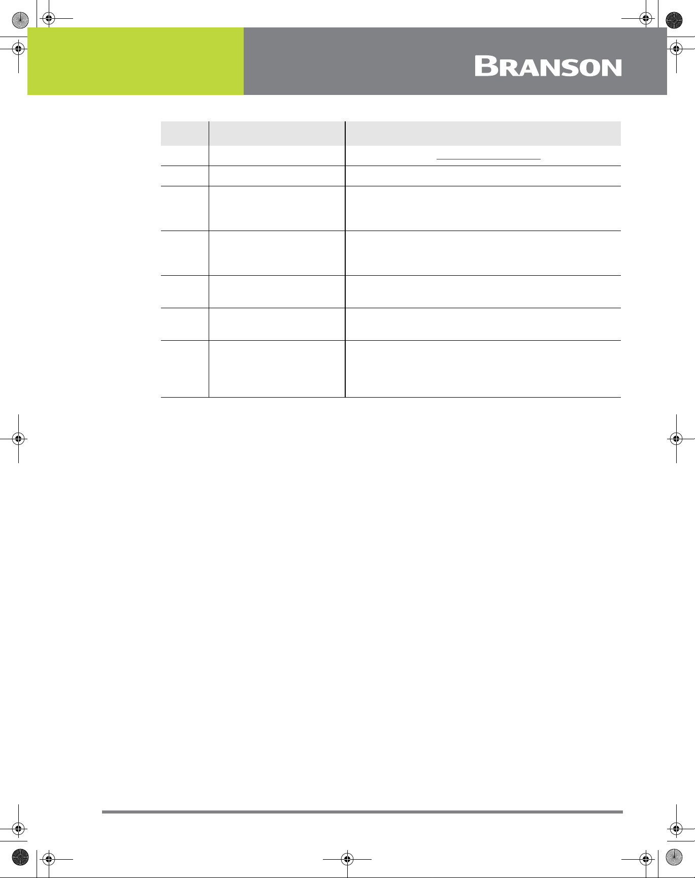
Table 1.2 Branson Contact
What you need help with or information
about
Information about new welding systems
or components
Application and Setup questions on the
welding system
Application assistance on the Horns and
Tooling
Technical questions about the welding
system
Technical questions about Horns and
Tooling
Ordering new parts Parts Store 877-330-0406
RGA’s, Request for Repair, Status of a
Repair
System Automation/Hookup Information Product Support
Whom to Call
Your local Br anson Rep
or Branson Customer
Service
Welding Applications
Lab
ATG Lab
Welding Product
Support
ATG Lab
Welding Repair
Department
At this
Extension #
203-796-0400
Ext 384
203-796-0400
Ext 368
203-796-0400
Ext 495
203-796-0400
Ext 355, 551
203-796-0400
Ext 495
877-330-0405
203-796-0400
Ext 355, 551
My Local Branson Representative's name is:
_______________________________________________________________________
I can reach this representative at:
_______________________________________________________________________
10 100-214-251 REV. 05

100-214-251 IWoper.book Page 11 Friday, June 16, 2017 4:12 PM
1.5.4 Pack and Ship the Equipment
1. Carefully pack the system in original packing material to avoid shipping damage. Plainly show the
RGA number on the outside of cartons as well as inside the carton along with the reason for
return. Make a list of all components packed in the box. KEEP YOUR MANUAL.
2. Return general repairs by any convenient method. Send priority repairs by air freight. Prepay the
transportation charges FOB the repair site.
NOTICE
Items that are sent Freight Collect will be refused.
100-214-251 REV. 05 11

100-214-251 IWoper.book Page 12 Friday, June 16, 2017 4:12 PM
1.6 Obtaining Replacement Parts
You can reach Branson Parts Store at the following telephone numbers:
Branson Part Store
direct telephone number: 877-330-0406
fax number: 877-330-0404
Many parts can be shipped the same day if ordered before 2:30 p.m., Eastern time.
A parts list is found in Chapter 7: Maintenance of this manual, listing descriptions and EDP
part numbers. If you need replacement parts, coordinate the following with your
purchasing agent:
• Purchase order number
• ‘Ship to’ information
• ‘Bill to’ information
• Shipping instructions (air freight, truck, etc.)
• Any special instructions (for example, “Hold at the airport and call”). Be sure to give a name and
phone number
• Contact name information
12 100-214-251 REV. 05

100-214-251 IWoper.book Page 13 Friday, June 16, 2017 4:12 PM
Chapter 2: The 2000IW/IW+ Welder
2.1 Models Covered . . . . . . . . . . . . . . . . . . . . . . . . . . . . . . . . . . . . . . . . . 14
2.2 Overview of these Models . . . . . . . . . . . . . . . . . . . . . . . . . . . . . . . . . 15
2.3 Compatibility with Branson Products. . . . . . . . . . . . . . . . . . . . . . . . . 18
2.4 Features . . . . . . . . . . . . . . . . . . . . . . . . . . . . . . . . . . . . . . . . . . . . . . . 19
2.5 Front Panel Controls. . . . . . . . . . . . . . . . . . . . . . . . . . . . . . . . . . . . . . 20
2.6 Rear Panel . . . . . . . . . . . . . . . . . . . . . . . . . . . . . . . . . . . . . . . . . . . . . 27
2.7 System Inputs/Outputs . . . . . . . . . . . . . . . . . . . . . . . . . . . . . . . . . . . 29
2.8 Glossary of Terms. . . . . . . . . . . . . . . . . . . . . . . . . . . . . . . . . . . . . . . . 31
100-214-251 REV. 05 13

100-214-251 IWoper.book Page 14 Friday, June 16, 2017 4:12 PM
2.1 Models Covered
This manual contains instructions for installing, setting up and operating a 2000IW and
2000IW+ Series Integrated Welders for 1100, 2200, and 3300 Watt output.
14 100-214-251 REV. 05

100-214-251 IWoper.book Page 15 Friday, June 16, 2017 4:12 PM
2.2 Overview of these Models
Figure 2.1 2000IW/IW+ Series Integrated Welder
The 2000IW and IW+ Series Integrated Welders are ultrasonic plastic joining systems.
They are used for welding plastic parts together by staking, insertion, swaging and
degating.
These welders are self contained, free standing welding systems designed for upright
vertical operation. Both the IW and IW+ Welders are available in 3 power levels, 1100
Watts, 2200 Watts, and 3300 Watts.
• For manual applications, welders can contain a base assembly with 2 Palm Buttons and an
Emergency Stop knob
• For Automated applications, welders can contain a hub in place of the base assembly
A typical setup will be with a standard 40-inch column (4, 5 and 6 foot lengths are also
available).
NOTICE
It is advisable to have non standard length columns installed at the factory.
An enclosure housing the carriage and slide system, the pneumatic system, the power
supply and the Control Module. The Control Module consists of a Controller Board and a
keyboard/display board.
A linear optical encoder provides detailed weld distance information, IW+ only.
100-214-251 REV. 05 15

100-214-251 IWoper.book Page 16 Friday, June 16, 2017 4:12 PM
2.2.1 Carriage and Slide System
The carriage is driven by a double-acting air cylinder, mounted on a linear, ball-bearing
slide. The slide system is based on eight sets of preloaded, permanently lubricated
bearings. These provide consistent, precise alignment of the horn, smooth linear motion,
and long-term reliability.
2.2.2 Pneumatic System
The pneumatic system consists of a solenoid valve, and air cylinder, and a Pressure
Regulator with an air-pressure gauge. The carriage’s rate of descent is adjusted by the
Down Speed control on the welder’s front panel. The rate of ascent is fixed.
As the carriage travels up and down, cooling air from the exhaust air of the solenoid valv e
is directed through the carriage to the converter.
2.2.3 Power Supply Module
The Power Supply Module converts conventional 50/60 Hz line current ultr asonic energy at
the resonant frequency of your Converter-Booster-Horn Stack. The Module Controller
ensures maximum reliability by terminating ultrasonic energy if the welder is operated
under adverse conditions. This protects both the power supply module and other welder
components. The controller also tracks and compensates for changes in horn frequency, if
necessary. These changes may occur due to increased temperatures, wear on the horn
face, or material buildup on the horn.
2.2.4 System Control Module
The System Control Module consists of a Controller Board and a Keyboard/Display board.
It controls the power supply module and the welder’s pneumatic functions. The keyboard/
display board allows the user to change weld parameters via the front panel displays and
switches.
2.2.5 Linear Optical Encoder, a 2000IW+ only feature.
The Linear Optical Encoder is a sensing device that tracks carriage movement. The
resolution of the encoder is 0.0001 in / 0.0025 mm.
NOTICE
The linear optical encoder reading will vary from the actual distance the carriage travels
by no more that 1/4 in / 6 mm, due to the setting of the Upper Limit Switch (ULS). This
distance is consistent from cycle to cycle.
Information from the linear optical encoder is used:
• To determine the relative position of the carriage at any point during the weld cycle.
• To terminate the weld by absolute distance, the total distance the carriage trav els from an upper
limit position (ULS) to a preset lower limit position.
• To terminate the weld by collapse distance, the total distance the carriage travels from the
Dynamic Trigger Switch (TRS) to a preset lower limit position.
16 100-214-251 REV. 05

100-214-251 IWoper.book Page 17 Friday, June 16, 2017 4:12 PM
2.2.6 Upper Limit Switch
The optical Upper Limit Switch (ULS) signals the control circuits in the Controller that the
carriage has returned to the top of its stroke and the welder is ready to start another weld
cycle.
The Controller uses this ULS signal to perform various control functions. For example:
• Indexing control, in automated systems, the Ready signal developed by the Controller after the
ULS is activated can be used by external devices to prevent movement of the material handling
equipment (indexing) when the horn is not fully retracted.
• Electronic pretriggering, the Controller can use the ULS signal to activate ultrasonic energy
before the horn contacts the workpiece. Pretriggering is used with large of difficult-to-start horns
and in a variety of applications.
2.2.7 User I/O Connector
External controls and devices, such as ALARMS, WELD ON and EXTERNAL RESET signals,
are available through +24V DC interface on the back panel of the welder. In addition, a
READY signal is available as both +24V DC and isolated contact closure. Using this
interface, selected faults or weld errors sensed by the welder can be communicated
outside the welder for monitoring cycles and sorting suspect workpieces.
2.2.8 Dynamic Triggering and Follow-Through
Many weld applications require that force be applied to the workpiece before ultrasonic
energy is activated. To achieve this, the welder contains a Dynamic Triggering
Mechanism, located between the air cylinder and the carriage. The Dynamic Triggering
Mechanism initiates (triggers) ultrasonic energy after a preset force is applied to the
workpiece. Dynamic follow-through maintains a consistent force on the workpiece during
the weld collapse. The system helps provide uniform weld quality.
The calibrated TRIGGER PRESSURE control, located on the front panel, allows you to
record and duplicate the dynamic triggering force.
100-214-251 REV. 05 17

100-214-251 IWoper.book Page 18 Friday, June 16, 2017 4:12 PM
2.3 Compatibility with Branson Products
The 2000IW/IW+ Series Integrated Welders are compatible for use with either a standard
base or a hub for automation. The CJ20 converter is used for the 1100, 2200, and 3300
Watt units.
18 100-214-251 REV. 05

100-214-251 IWoper.book Page 19 Friday, June 16, 2017 4:12 PM
2.4 Features
The 2000IW/IW+ Series Integrated Welders can perform ultrasonic welding, inserting,
staking, spot welding, swaging, degating, and continuous ultrasonic operations. It is
designed for automated, semi-automated and/or manual production operations. The
following list describes the control features of the welder.
Afterburst: This feature allows you to turn on the ultrasonics after the weld and hold
steps to reliably release parts from the horn.
Alarms, Process: These are set values used for part quality monitoring.
Autotuning: Ensures that the welder is running at peak efficiency.
Cycle Aborts: These are user programmed conditions (ground detect, IW only) at which
the cycle is terminated. These can be used as safety limits to save wear and tear on the
system and your tooling.
Downspeed: Sets the advance speed of the horn towards the workpiece.
English (USCS)/Metric Units: This feature allows the welder to be programmed in the
local units in use.
Horn Down Display, IW+ only: During Horn Down, the absolute Distance is displayed
digitally so that you can determine correct values for settings.
Horn Down Mode: A manual procedure used to verify system setup and alignment.
Limits: A class of user-definable process alarms that alert you if a part falls into a range
that you classified as reject parts.
Memory: When Memory is turned on, weld parameters at the end of the cycle will be
entered.
Membrane Keyboard: For high reliability and immunity from factory dust and oils.
Pretrigger: This feature allows you to turn on the ultrasonics before contact with the part
to increase performance.
Ramp Starting: The starting of the Power Supply Module and horn is done at the
optimum rate to reduce electrical and mechanical stress on the system.
Seek: Ensures operation at resonance, minimizes tuning errors, and operates the stack at
low amplitude (approximately 5%), then provides a means of sensing and storing the
resonant operating frequency.
Start-up Diagnostics: At start-up, the controls test the major system components.
Timed Seek: When turned ON, will do a Seek once every minute to update horn resonant
frequency to memory. This is especially useful when the welding process affects the actual
temperature of the horn. causing a resonant frequency shift.
100-214-251 REV. 05 19

100-214-251 IWoper.book Page 20 Friday, June 16, 2017 4:12 PM
2.5 Front Panel Controls
Figure 2.2 Front Panel Controls, IW
Table 2.1 Front Panel Controls IW
Item Name Function
1 Pressure Gauge
2 Pressure Regulator
3 Down Speed Control
20 100-214-251 REV. 05
Indicates the amount of air pressure applied to a
cylinder; dual-calibrated at 0-100 psig/o-700 kPa.
Adjusts amount of air pressure applied to cylinder;
range of 5-100 psig/35-700 kPa. Pull to set, push
to lock.
Controls rate of carriage descent, multi-turn color
coded, each turn calibrated at 0-9. Pull red locking
to set; push locking ring to lock. Return rate is
fixed.
100-214-251 IWoper.book Page 21 Friday, June 16, 2017 4:12 PM
Table 2.1 Front Panel Controls IW
Item Name Function
4 Autotune Label Refer to Section 7.4.1 Manual Tuning
5 Front Panel Displays Refer to next Section
6 Stroke Indicator
7 Trigger Pressure Control
Provides a quick method of determining relative
carriage travel during a weld cycle; indicates 0-4 in
0-100 mm).
Selects dynamic triggering pressure; calibrated 124 in half-steps/48 detents corresponding to a
force range of 15-200 lbs/67-890 N.
8 Carriage Door
9
Mechanical Stop
Locking Nut
Provides access to the converter-booster-horn
stack; secured by 4 captive hex screws.
Locks the mechanical stop to desired depth.
Limits the distance the carriage travels to prevent
10 Mechanical Stop
horn from contacting the fixture or nest when no
workpiece is in place; adjustment is approximately
0.04 in/1 mm per rotation.
This multi-turn control is calibrated in color rings, visible in slots.
100-214-251 REV. 05 21

100-214-251 IWoper.book Page 22 Friday, June 16, 2017 4:12 PM
Figure 2.3 Front Panel Displays, IW
Table 2.2 Front Panel Displays, IW
Item Name Function
This 20 segment bargraph displays the power level
during the Test mode; or the power applied to the
workpiece during a weld cycle. While in READY state,
1 Power Bargraph
the graph display the peak power of the last weld cycle.
These readings can be expanded by altering DIP switch
settings. When using the 2x scale, the uppermost
segment will blink. Refer to section 4.11.1 Setting DIP
Switches for further information on DIP settings.
During a weld cycle, indicates the correct weld state
2 Numeric Display
code enabled, or the currently selected parameter’s
value. At the end of the weld cycle, it displays alarms.
Once you have selected weld parameters to change,
these four switches increase or decrease your selected
parameters displayed in the NUMERIC DISPLAY. From
left to right, these switches are referred to as the FAST
3 Up/Down Switches
DOWN switch, the SLOW DOWN switch, the SLOW UP
switch, and the FAST UP switch. Pressing these
switches will have no effect until you have selected
parameters to change. These switches will be disabled
when Display Lock is active.
4 Power Indicator Indicates that power to the welder is on.
Resets any resettable or latchable alarm condition
(indicated by the switch LED blinking). Holding RESET
5 Reset Switch
prevents a weld cycle from starting. Releasing RESET
returns the welder to the READY state, if there are no
non-resettable errors.
22 100-214-251 REV. 05

100-214-251 IWoper.book Page 23 Friday, June 16, 2017 4:12 PM
Table 2.2 Front Panel Displays, IW
Item Name Function
6 Test Switch
7 Horn Down Switch
Activates ultrasonic power and places the ultrasonic
power supply module into Test (autotune) mode for
approximately 6 seconds). While this switch is pressed,
power displays on both the NUMERIC DISPLAY and the
POWER BARGRAPH. When you release TEST, the welder
returns to the READY state. You can select the scale
factor for Test mode by setting the Test Scale Multiplier
DIP Switch to 1x or 2x. Refer to Section 4.11.1 Setting
DIP Switches for further information about DIP
settings.
Selects the HORN DOWN mode. When pressed, the
switch LED will light. Pressing the START SWITCHES
while in the Horn Down mode will bring the carriage
down without triggering ultrasonics. Pressing the
switch again will de-select HORN DOWN mode.
8 AB Time Switch
9 AB Delay Switch
10 Hold Time Switch
11 Weld Time Switch
Selects the afterburst TIME parameter for modification
when display lock is inactive; displays the AB TIME
parameter in the NUMERIC DISPLAY, and lights the AB
TIME switch LED.
Selects the Afterburst DELAY parameter for
modification when display lock is inactive; displays the
AB DELAY parameter in the NUMERIC DISPLAY, and
lights the AB DELAY switch LED.
Selects the Hold Time parameter for modification when
display lock is inactive; displays the Hold parameter in
the NUMERIC DISPLAY, and lights the Hold Time switch
LED.
Selects the Weld Time par ameter for modification when
display lock is inactive; displays the Weld parameter in
the NUMERIC DISPLAY; and lights the Hold Time switch
LED.
100-214-251 REV. 05 23

100-214-251 IWoper.book Page 24 Friday, June 16, 2017 4:12 PM
Figure 2.4 Front Panel Displays, IW+
Table 2.3 Front Panel Displays, IW+
Item Name Function
This 20 segment bargraph displays the power level
during the Test mode; or the power applied to the
workpiece during a weld cycle. While in the READY
state, the graph displays the peak power of the last
1 Power Bargraph
weld cycle. These readings can be expanded by
altering DIP switch settings. When using the 2x scale,
the uppermost segment will blink. Refer to section
4.11.1 Setting DIP Switches for further information
about DIP settings.
During a weld cycle, indicates the current weld state
2 Numeric Display
code, if enabled, or the currently selected parameter’s
value. At the end of the weld cycle, it displays alarms.
Once you have selected weld parameters to change,
these four switches increase or decrease your selected
parameters displayed in the NUMERIC DISPLAY. From
left to right, these switches are referred to as the FAST
3 Up/Down Switches
DOWN switch, the SLOW DOWN SWITCH, the SLOW
UP switch, and the FAST UP switch. Pressing these
switches will have no effect until you have selected
parameters to change. These switches will be disabled
when Display Lock is active.
+ Limit Switch, a
4
2000IW+ only
feature
- Limit Switch, a
5
2000IW+ only
feature
Selects the maximum value for the mode you are in.
When pressed, the switch LED will light. This switch is
only active after you have pressed MODE.
Selects the minimum value for the mode you are in.
When pressed, the switch LED will light. This switch is
only active after you have pressed MODE.
6 Power Indicator Indicates that power to welder is ON.
24 100-214-251 REV. 05

100-214-251 IWoper.book Page 25 Friday, June 16, 2017 4:12 PM
Table 2.3 Front Panel Displays, IW+
Item Name Function
7 Reset Switch
8 Test Switch
Resets any resettable or latchable alarm condition
(indicated by the switch LED blinking). Holding RESET
prevents a weld cycle from starting. Releasing RESET
returns the welder to the ready state, if there are no
non-resettable errors.
Activates ultrasonic power and places the ultrasonic
power supply module into Test (autotune) mode for
approximately 6 seconds. While this switch is pressed,
power displays on both the NUMERIC DISPLAY and the
POWER BARGRAPH. When you release TEST, the
welder returns to the READY state. You can select the
scale factor for Test mode by setting the Test Scale
Multiplier DIP switch to 1x or 2x. Refer to section
4.11.1 Setting DIP Switches for further information
about DIP settings.
9 Horn Down Switch
Actual Switch, a
10
2000IW+ only
feature
11 AB Time Switch
Selects the Horn Down mode. When pressed, the
switch LED will light and the NUMERIC DISPLAY will
show the current linear encoder reading. If you have
selected USCS units, 0.0000” (representing inches)
will appear on the NUMERIC DISPLAY; if you have
selected SI units, 0.0000 (representing millimeters)
will appear. Pressing the START SWITCHES while in
the Horn Down mode will bring the carriage down
without triggering ultrasonics. Pressing the switch
again will de-select HORN DOWN mode.
Selects for display the actual value for the previous
weld. Each succeeding press will display the actual
value of each of the three modes in turn, displaying
the actual time or actual distance and lighting the
relevant MODE INDICATOR LED. The fourth press will
return the welder to the READY state. Although the
MODE INDICATOR LEDs change with each press of
ACTUAL, the welder mode does not change. Pressing
MODE will display the current mode again.
Selects the Afterburst TIME parameter for modification
when display lock is inactive; displays the AB TIME
parameter in the NUMERIC DISPLAY, and lights the AB
TIME switch LED.
Selects the Afterburst DELAY parameter for
12 AB Delay Switch
modification when display lock is inactive; displays the
AB DELAY parameter in the NUMERIC DISPLAY, and
lights the AB DELAY switch LED.
Selects the Hold Time parameter for modification
13 Hold Time Switch
when display lock is inactive; displays the Hold
parameter in the NUMERIC DISPLAY, and lights the
Hold Time switch LED.
100-214-251 REV. 05 25

100-214-251 IWoper.book Page 26 Friday, June 16, 2017 4:12 PM
Table 2.3 Front Panel Displays, IW+
Item Name Function
Selects between Time and Collapse and Absolute
Distance modes; changes the display for the selected
mode, and allows for changes in mode or mode
parameters when Display Lock is inactive.
14
NOTICE
Mode Switch, a
2000IW+ only
feature
In Collapse or Absolute Distance Modes the weld time parameter acts as an overriding
condition. Ensure Time is setup to allow for the collapse or absolute distances to be
attained during a weld.
15
Mode Indicator
LEDS, a 2000IW+
only feature
Light once you have selected the mode you wish to
alter; indicate the mode selected.
26 100-214-251 REV. 05

100-214-251 IWoper.book Page 27 Friday, June 16, 2017 4:12 PM
2.6 Rear Panel
The grayed out portion shows placement of the optional Accessory Input/Output (1), and
Ground Detect inputs (2, 3) and the position of the mounting plate supplied in their
respective kits (see below).
Figure 2.5 Rear Panel
Table 2.4 Rear Panel
Item Name Function
An advanced feature that allows connection of Power
Out, Memory, Seek, Frequency, Frequency Offset,
1
100-214-251 REV. 05 27
Accessory Input/
Output
Power Supply Module Status Outputs, Amplitude
Output and Amplitude Control Input. Requires
Accessory Input/Output kit 101-063-721. 15 pin male
connector.

100-214-251 IWoper.book Page 28 Friday, June 16, 2017 4:12 PM
Table 2.4 Rear Panel
Item Name Function
2
3
Ground Detect, 15
pin female connector
Ground Detect, 3 pin
connector
An optional 2000IW only feature, allows ultrasonic
energy to be turned off when the horn comes in
contact with your electrically isolated fixture or anvil.
Requires Ground Detect Kit, 1010-063-343.
25 pin D-shell connector provides a +24V DC interface
for external controls and devices. ALARMS, WELD ON
and EXTERNAL RESET signals are available. In
4
User I/O, Alarm
Connector
addition, a READY signal is available as both +24V DC
and isolated contact closure. Using this connector,
selected faults or weld errors sensed by the welder can
be communicated outside the welder for monitoring
cycles and sorting suspect workpieces. Connector 4 is a
25 pin female.
5 Start Connector
Connects the welder to its base or to customer
supplied start signals. Connector 5 is a 9 pin male.
6 Air Filter Filters contaminated from the air entering the welder.
7 Line Cord Connects the welder to your power source.
28 100-214-251 REV. 05

100-214-251 IWoper.book Page 29 Friday, June 16, 2017 4:12 PM
2.7 System Inputs/Outputs
The inputs provided to the welder are used to control the weld cycle and monitor the
2000IW/IW+ hardware.
2.7.1 START SWITCHES/START Signal - START Connector
These inputs are used to start the weld cycle. To start a weld cycle, both START SWITCH
inputs must become active within 100 (IW) or 200 (IW+) ms of each other, and remain
active until TRS activates, or an error will be generated and no weld will be performed
Errors will also be generated if the START SWITCHES do not remain active until the TRS
input becomes active (for maintained software), or are not inactive within 4 seconds after
the solenoid valve drive circuits have been disabled
Figure 2.6 Base, Showing START SWITCHES and Base Cable
2.7.2 EXTERNAL RESET - ALARM (User I/O) Connector
This input, when activated, will simulate pressing RESET (refer to Figure 2.4 Front Panel
Displays, callout 5, IW, 7 IW+). You cannot start a weld cycle if the EXTERNAL RESET line
is active.
2.7.3 READY Signal - ALARM Connector
The welder uses the Upper Limit Switch (ULS) input to determine when the carriage has
started to descend and when it has reached its “home” position on its return at the end of
the weld cycle.
The Controller evaluates other system conditions as well before generating the READY
signal. It evaluates if any alarm conditions exist. Monitoring this signal indicates that the
welder is at rest and it is ready to cycle (for example not in TEST, HORN DOWN, latched
alarm condition or system fault).
2.7.4 GENERAL ALARM - Alarm Connector
GENERAL ALARM is a signal which indicates that an alarm has been sensed. Resetting
alarms and resolving system faults clears this alarm signal. Refer to 6.5 Weld Cycle State
Displays and Alarms for further information.
100-214-251 REV. 05 29

100-214-251 IWoper.book Page 30 Friday, June 16, 2017 4:12 PM
2.7.5 WELD ON Signal - Alarm Connector
The WELD ON signal indicates you are in the Weld Time portion of the cycle and that TRS
is active. This signal indicates when a start signal can be released.
In any of he following situations, an error will be generated:
• The input becomes inactive while the welder is in the READY state
• The input does not become inactive within 4 seconds after the solenoid valves are activated
• The input becomes active before weld timing begins during a weld cycle
• The input does not become active within 4 seconds after the solenoid valves are deactivated
30 100-214-251 REV. 05

100-214-251 IWoper.book Page 31 Friday, June 16, 2017 4:12 PM
2.8 Glossary of Terms
The following terminology may be encountered when using or operating a 2000-series
ultrasonic welding system. Some of these terms may not be available in all configur ations:
AB Amplitude: The amplitude at the horn face during the afterburst step.
AB Delay: Time delay between the end of the hold and the start of afterburst.
AB Time: The time duration of the afterburst.
Absolute Distance: The distance the horn has travelled from home.
Absolute Mode: A mode of operation in which the weld is terminated when a user-
specified distance from the home position has been reached.
Absolute Position: The position of the Actuator from the home position.
Accept-as-is: A disposition permitted for a nonconforming item when it can be
established that the item is satisfactory for its intended use without violating safety or
functional requirements.
Actual: A reported value that occurred during the weld cycle. The converse is the set
parameter that was requested during the setup.
Actuator: The section of the Integrated Welder that houses the converter, booster, and
horn assembly in a rigid mounting allowing it to move up and down either mechanically or
pneumatically to apply a predetermined pressure on the workpiece.
Afterburst: Ultrasonic energy applied after the hold step. Used to break away sticking
parts from the tooling.
Alarm Beeper: An audible signal that sounds when a general alarm has occurred.
Amplitude: The peak-to-peak movement at the horn face. Always expressed as a
percentage of the maximum.
Amp Control: The ability to set amplitude digitally or by an external control.
Automatic: A pretrigger condition indicating that pretrigger engages when the actuator
leaves the upper limit switch.
Beep: An audible signal produced by the Branson control board. Used to alert the
operator to an unexpected condition or that trigger has been reached.
Booster: A one-half wavelength long resonant metal section mounted between the
converter and horn, usually having a change in cross-sectional area between the input
and output surfaces. Mechanically alters the amplitude of vibration at the driving surface
of the converter.
Clamping Force: The pressure exerted by the horn on the workpiece.
Cold Start: A user operation to establish a setup to a new, initial minimum set of weld
parameters. Refer to
carefully.
Collapse Distance: The vertical distance your part will be collapsed before termination of
ultrasonics.
Collapse Mode: A mode of operation in which the weld is terminated when the part has
been collapsed by a user-specified distance.
Custom Logic: Allows the operator to choose either High (24V) or Low (0V) logic for
switches to be used in interfacing the welder to an automated system.
Cycle Aborts: There are no cycle aborts except Ground Detect, which is available in IW
only.
100-214-251 REV. 05 31
6.6 Resetting the System, “Resetting the System”. Note: Use

100-214-251 IWoper.book Page 32 Friday, June 16, 2017 4:12 PM
Downspeed: The rate of speed of the actuator from the home position to the part.
General Alarm: An alarm that occurs due to a system fault and/or tripping a limit.
Ground Det. Cutoff: Immediately terminates the weld process, including the hold step,
when a ground detect has occurred.
Ground Detect Mode: In this mode of operation, ultrasonics are terminated after
detection of a ground condition between the horn and fixture or anvil.
Horn Down: A mode in which ultrasonics are locked out and the user can advance the
Actuator for setup and alignment.
Linear Encoder: Provides carriage distance measurement during the welder cycle. IW+
only.
Pretrigger: The setting that causes ultrasonics to start before contact with the part.
Ready Position: State in which the welder is retracted and ready to receive the start
signal.
Limits: User-definable limits at which the violating cycle is identified as having produced a
bad part.
Required: State used with limits indicating that a reset will be required when the limit is
exceeded. The reset is accomplished by using the reset key on the front of the Integrated
Welder, or by external reset at the User I/O.
Reset Required: State used with alarms indicating that a reset will be required before a
cycle can be run. The reset is accomplished by using the reset key on the front of the
Integrated Welder, or by external reset at the User I/O.
Scrub Time: The amount of time after detection of a ground condition (option IW only) to
the termination of ultrasonics.
Seek: A setting where ultrasonics are on at 5% amplitude for the purpose of finding the
resonant frequency of the stack.
Stack: Converter, Booster, and Horn.
Test Scale: The magnification of the power bar scale on the front panel while the Test key
is pushed.
Time Mode: Terminates the ultrasonics at a user-specified time. Note: In Collapse or
Absolute Distance Modes the weld time parameter acts as an overriding condition. Ensure
Time is setup to allow for the collapse or absolute distances to be attained during a weld.
Timeout: A time at which the ultrasonic energy terminates if the main control parameter
has not been reached.
Trigger Beeper: An audible signal sounded when the trigger is made.
Upper limit switch (uls): A switch when activated indicates the actuator is in the home
position.
User-defined limits for process resultants, where – is the user-defined lower limit, and
+ is the user defined upper limit:
–/+ Time: The weld time reached during the weld.
-/+ Abs D: The absolute distance from the Home position reached during the weld.
–/+ Col D: The collapse distance reached during the weld.
Weld Time: The time for which ultrasonics are on.
32 100-214-251 REV. 05

100-214-251 IWoper.book Page 33 Friday, June 16, 2017 4:12 PM
Chapter 3: Delivery and Handling
3.1 Shipping and Handling . . . . . . . . . . . . . . . . . . . . . . . . . . . . . . . . . . . . 34
3.2 Receiving . . . . . . . . . . . . . . . . . . . . . . . . . . . . . . . . . . . . . . . . . . . . . . 35
3.3 Unpacking. . . . . . . . . . . . . . . . . . . . . . . . . . . . . . . . . . . . . . . . . . . . . . 36
3.4 Returning Equipment . . . . . . . . . . . . . . . . . . . . . . . . . . . . . . . . . . . . . 37
100-214-251 REV. 05 33

100-214-251 IWoper.book Page 34 Friday, June 16, 2017 4:12 PM
3.1 Shipping and Handling
CAUTION General Warning
The Integrated Welder internal components are sensitive to static
discharge. Many components can be harmed if the unit is dropped,
shipped under improper conditions or otherwise mishandled.
3.1.1 Environmental Specifications
The Integrated Welder is an electronic unit that converts line voltage to ultrasonic energy
and controls user input for regulating the weld process. Its internal components are
sensitive to static discharge, and many of its components can be harmed if the unit is
dropped, shipped under improper conditions, or otherwise mishandled.
The following environmental guidelines should be respected in the shipping of the
Integrated Welder.
Table 3.1 Environmental Specifications
Environment Range
Storage / Shipping Temperature
Shock / Vibration (transit)
Humidity 30% to 95%, non-condensing
-25° C to +55° C (-13° F to +131° F);
up to +70° C (+158° F) for 24 hours
40 g shock / 0.5 g and (3-100 Hz) vibration
per ASTM 3332-88 and 3580-90
34 100-214-251 REV. 05

100-214-251 IWoper.book Page 35 Friday, June 16, 2017 4:12 PM
3.2 Receiving
The Integrated Welder is a sensitive electronic device. Many of its components can be
harmed if the unit is dropped or otherwise mishandled.
CAUTION Heavy Object
Scope of Delivery
The Integrated W elder is heavy . Handling, unpacking, and installation
may require assistance or the use of a lifting device.
Branson Integrated Welder units are carefully checked and packed before dispatch. It is
recommended, however, that you follow the inspection procedure below after delivery.
3.2.1 To inspect the Integrated Welder when it is delivered, take the following steps:
Table 3.2 Inspection upon delivery
Step Action
1 Verify that all parts are complete according to the packing slip.
2 Check the packing and the unit for damage (visual inspection).
3 Report any damage claims to your carrier immediately.
4
NOTICE
If the goods delivered have been damaged during shipping, please contact the
forwarding agent immediately. Retain packing material (for possible inspection or for
sending back the unit).
Determine if any component has become loose during shipping and, if
necessary, tighten screws.
CAUTION Heavy Object
The Integrated W elder is heavy . Handling, unpacking, and installation
may require the assistance of a colleague or the use of lifting
platforms or hoists.
100-214-251 REV. 05 35

100-214-251 IWoper.book Page 36 Friday, June 16, 2017 4:12 PM
3.3 Unpacking
The Integrated Welder is fully assembled. It is shipped in a sturdy cardboard box. Some
additional items are shipped in the box with the Integrated Welder.
Table 3.3 When unpacking the Integrated Welder, take the following steps
Step Action
1 Unpack the Integr ated W elder as soon as it arrives. Sa ve the packing material.
2 Inspect the controls, indicators, and surface for signs of damage.
3
NOTICE
If damage has occurred, notify the shipping company immediately. Retain packing
materials for inspection.
Remove the cover of the Integrated Welder (
check if any components became loose during shipping.
Table 7.2 Replacement Parts) to
36 100-214-251 REV. 05

100-214-251 IWoper.book Page 37 Friday, June 16, 2017 4:12 PM
3.4 Returning Equipment
If you are returning equipment to Branson Ultrasonic Corporation, please call your
Customer Service Representative to receive approval to return goods to Danbury.
If you are returning equipment for repair refer to Chapter 1: Safety and Support, Section
1.5 Returning Equipment for Repair, of this manual, for appropriate procedure.
100-214-251 REV. 05 37

100-214-251 IWoper.book Page 38 Friday, June 16, 2017 4:12 PM
38 100-214-251 REV. 05

100-214-251 IWoper.book Page 39 Friday, June 16, 2017 4:12 PM
Chapter 4: Installation and Setup
4.1 About Installation. . . . . . . . . . . . . . . . . . . . . . . . . . . . . . . . . . . . . . . . 40
4.2 Handling and Unpacking. . . . . . . . . . . . . . . . . . . . . . . . . . . . . . . . . . . 41
4.3 Take Inventory of Small Parts . . . . . . . . . . . . . . . . . . . . . . . . . . . . . . 44
4.4 Installation Requirements . . . . . . . . . . . . . . . . . . . . . . . . . . . . . . . . . 45
4.5 Installation Steps . . . . . . . . . . . . . . . . . . . . . . . . . . . . . . . . . . . . . . . . 49
4.6 Accessory Input/Output Option. . . . . . . . . . . . . . . . . . . . . . . . . . . . . 60
4.7 Guards and Safety Equipment . . . . . . . . . . . . . . . . . . . . . . . . . . . . . . 61
4.8 Assemble the Acoustic Stack . . . . . . . . . . . . . . . . . . . . . . . . . . . . . . . 62
4.9 Installing the Ultrasonic Stack in the Integrated Welder . . . . . . . . . 65
4.10 Adjusting Welder Height and Aligning the Horn . . . . . . . . . . . . . . . . 67
4.11 Adjusting the Mechanical Stop . . . . . . . . . . . . . . . . . . . . . . . . . . . . . . 68
4.12 Testing the Installation . . . . . . . . . . . . . . . . . . . . . . . . . . . . . . . . . . . 72
4.13 Still Need Help? or Parts? Have Questions?. . . . . . . . . . . . . . . . . . . . 73
100-214-251 REV. 05 39

100-214-251 IWoper.book Page 40 Friday, June 16, 2017 4:12 PM
4.1 About Installation
This Chapter is intended to help the installer with the basic installation and setup of your
new 2000 Series Integrated Welder. This chapter will bring the reader to the point at
which the system is functionally “ready to weld”.
CAUTION Heavy Object
The Integrated W elder weighs 145 pounds. Handling, unpacking, and
installation can require help or the use of lifting platforms or hoists.
International safety labels are found on the 2000IW/IW+ Integrated Welder. Those that
are of importance during installation of the system are identified in the figures in this and
other chapters of the manuals.
40 100-214-251 REV. 05

100-214-251 IWoper.book Page 41 Friday, June 16, 2017 4:12 PM
4.2 Handling and Unpacking
If there are any visible signs of damage to the shipping containers or the product, or you
later discover hidden damage, NOTIFY YOUR CARRIER IMMEDIATELY. Save the packing
material.
1. Unpack the 2000-series components as soon as they arrive. Refer to the following procedures
2. Verify you have all of the equipment ordered. Some components are packed inside other boxes
3. Inspect the controls, indicators, and surfaces for signs of damage
4. Save all packing material, including the pallets and wood spacer blocks
4.2.1 Unpack the Integrated Welder
The Integrated Welder is heavy (145 lbs.) and packed in a protective shipping container.
The actuator toolkit is packed with the welder. A booster, converter and other components
may be packed inside the shipping container (depending on the equipment ordered).
• Integrated Welders are shipped on a wooden pallet with a cardboard box cover over protective
foam shells for support
• Heed the “This End Up” arrows and the “Open Top First” instructions. The packaging is designed
to be removed from the assemblies from an upright orientation only
Figure 4.1 Unpacking the Stand (2000IW/IW+ on a Base); right-side view of Stand
Converter
Booster
Tool Kit
Insert
Box
6-1/2 in.
18in.
53in.
32-1/2in.
Protective
Box
wood block
for shipping
1. Move the shipping container close to the intended installation location, leave it on the floor
2. Open the top of the box. Remove the insert from the top of the protective box, which may
contain the booster, converter, and the toolkit
3. Remove the staples at the bottom of the protective box. Lift the protective box off the pallet
100-214-251 REV. 05 41

100-214-251 IWoper.book Page 42 Friday, June 16, 2017 4:12 PM
CAUTION General Warning
The column and column support are under spring tension from the
counterbalance spring. Do NOT attempt to disassemble the column
from the stand, but always keep the column
support clamped together. When making height adjustments,
carefully and slowly release the clamps to control the motion, and
hold the stand to prevent sudden movements or injury.
4. Cut the two packing straps around the base and pallet. Pry off the two wooden shipping blocks
(to the rear of the base) which prevent the base from sliding on the pallet
5. The stand can now be moved into its desired location by sliding it off the pallet. Stands have a
lifting hook for the use of overhead hoists to lift the assembly in place
6. Remove the block of wood between the base and the column support by carefully loosening the
two column clamps (allowing the actuator to rise slightly, but not allow sudden movements) and
then cutting the shipping tape on the block of wood. RETIGHTEN THE COLUMN CLAMPS
7. Unpack the toolkit from the insert box, and other parts (converter, booster , cables, manuals, etc.)
that may have shipped with the stand. Save the packing material
8. Go to
4.3 Take Inventory of Small Parts
4.2.2 Stand (2000IW/IW+ on a Hub)
Figure 4.2 Unpacking the Stand (2000IW/IW+ on a Hub); Hub shown separately
Booster
Insert Box
18in.
Protective
Box
32-1/2in.
Shipping
Strap
Converter
Tool Kit
6-1/2in.
(loosen to remove
Hub from Column)
53 in.
Block of wood
for shipping
Note: Hubs may be lag-bolted to the
pallet for shipping purposes.
Two Hub Bolts
Hub
(shipped in place
on column, on pallet)
CAUTION General Warning
Heed the “This End Up” arrows and the “Open Top First” instructions.
The packaging is designed to be removed from the assemblies from
an upright orientation only.
42 100-214-251 REV. 05

100-214-251 IWoper.book Page 43 Friday, June 16, 2017 4:12 PM
1. Move the shipping container close to the intended installation location, leave it on the floor
2. Cut the two vertical packing straps, and open the top of the box. Remove the insert from the top
of the box, which can contain the booster, converter, and the toolkit. Set the insert box aside
3. Remove the staples at the bottom of the protective box. Lift the protective box off the pallet.
Flatten the box and lay it next to the pallet (you will lay the stand on it soon)
CAUTION General Warning
4. Cut the packing strap securing the column support to the pallet
The unit may tend to tip over. Stabilize the stand with the help of an
assistant.
CAUTION General Warning
The column and column support are under spring tension from the
counterbalance spring. Do NOT attempt to disassemble the column
from the stand, but always keep the column
support clamped together. When making height adjustments,
carefully and slowly release the clamps to control the motion, and
hold the stand to prevent sudden movements or injury.
5. Remove the block(s) of wood between the base and the support by slowly loosening the two
column clamps (allowing the stand to rise slightly) and then cutting the shipping tape on the
block of wood. RETIGHTEN THE COLUMN CLAMPS
6. Loosen the two hub bolts (for column clamping) on the hub
7. Lift the actuator and column from the pallet. Carefully lay the stand on its right side (NOT ON
THE SIDE WITH THE LINEAR ENCODER)
8. Remove the hub from the pallet and set it aside. Some hubs are bolted to the pallet from the top
9. Unpack the converter, booster, cables, manuals, and toolkit that may be in the insert box. Save
the packing material, including the blocks of wood
10.Go to Section
4.3 Take Inventory of Small Parts
NOTICE
The packaging may also include the converter and/or booster, if ordered.
Figure 4.3 Ultrasonic Converter (J-Type for stand use) and Booster
Converter
(J-type shown)
Booster
100-214-251 REV. 05 43

100-214-251 IWoper.book Page 44 Friday, June 16, 2017 4:12 PM
4.3 Take Inventory of Small Parts
Table 4.1 Small Parts Included (=x) with IW/IW+ integrated Welder
Part or Kit 20kHz Stand (Base) Stand (Hub)
T-Handle Wrench x x
Mylar Washer Kit x
20kHz Spanners (2) x
Fixture Bolts and Washer x
M8 Allen Wrench x x
4.3.1 Cables
For status/alarm interfacing with the 2000IW+ CE Welder, you may also need a J971
alarm cable. See Table 4.2 List of Cables for available lengths.
Table 4.2 List of Cables
P/N Length
101-240-020 Start Cable (J911) 8’ (req PLA)
For Start/Stop control in
automated machines
For Status/Alarm interfacing to
automated machines
101-240-015 Start Cable (J911) 15’ (req PLA)
101-240-010 Start Cable (J911) 25’ (req PLA)
101-240-021 Alarm Cable J971, 8 ft.
101-240-016 Alarm Cable J971, 15 ft.
101-240-011 Alarm Cable J971, 25 ft.
44 100-214-251 REV. 05

100-214-251 IWoper.book Page 45 Friday, June 16, 2017 4:12 PM
4.4 Installation Requirements
This section covers the location options, dimensions of the major assemblies,
environmental requirements, electrical requirements and factory air requirements, to help
you plan and execute your installation successfully.
4.4.1 Location
The Integrated Welder should only be operated in the vertical position. The Welder (on a
base) is often manually operated, using its base-mounted start switches, and so is
installed at a safe and comfortable workbench height (approximately 30-36 inches) with
the operator sitting or standing in front of the system. Stands (on hubs) are often used in
automated systems and may be manually or automatically loaded and unloaded.
WARNING General Warning
The stand may tip over if moved around the axis of its column, if not
properly secured. The work surface on which a stand is installed must
be sturdy enough to support it, and secure enough to not tip over
when the stand is adjusted during installation or setup.
The internal power supply module must be accessible for user parameter changes and
settings, so considerations must be made to be able to access the DIP switches. The
Welder should be positioned so it does not draw in dust, dirt or material via its internal
fan. Consideration should also be given to rear electrical and pneumatic connections,
approximately 6 in/150 mm. Refer to the illustrations on the pages that follow for a
dimensional drawing of each component. All dimensions are approximate and may vary
between models.
100-214-251 REV. 05 45

100-214-251 IWoper.book Page 46 Friday, June 16, 2017 4:12 PM
Figure 4.4 2000IW/IW+ Integrated Welder Dimensional Drawing
4.4.2 Environmental Specifications
Table 4.3 Environmental Specifications
Environmental Concern Acceptable Range
Humidity 30% to 95%, non-condensing
46 100-214-251 REV. 05

100-214-251 IWoper.book Page 47 Friday, June 16, 2017 4:12 PM
Table 4.3 Environmental Specifications
Environmental Concern Acceptable Range
Ambient Operating Temperature +5° C to +50° C (41° F to 122° F)
Operating Altitude Up to 1000 m
IP Rating 2X
4.4.3 Electrical Input Power Ratings
Plug the Welder into a single-phase, grounded, 3-wire, 50 or 60 Hz power source. lists
the current and fuse ratings for the various models.
Table 4.4 Input Power Requirements
1100 W 100V - 120V 13 Amp Max. @ 100V / 17 Amp CB NEMA 5-15P Plug
1100 W 200V - 240V 6.5 Amp Max. @ 200V / 8 Amp CB None supplied
2200 W 200V - 240V 14 Amp Max. @ 200V / 17 Amp CB None supplied
3300 W 200V - 240V 21 Amp Max. @ 200V / 20 Amp CB None supplied
4.4.4 Factory Air
The factory compressed air supply must be “clean (to a 5 micron level), dry and
unlubricated” air with a regulated maximum pressure of 100 psig (690 kPa). Depending
on your application, the welder requires between 35 to 100 psi. Stands include an in-line
air filter. Welders on Stands require a customer-provided air filter. Use a lockout device on
the air line if required.
CAUTION General Warning
Synthetic air compressor lubricants containing Silicone or WD-40 will
cause internal welder damage and failure due to the solvents
contained within these types of lubricants.
CAUTION General Warning
There should be no substitute for clean, dry air to run the welder. Use
of other types of gas could lead to premature degradation of seals.
Contact your Branson representative if you have any concerns.
100-214-251 REV. 05 47

100-214-251 IWoper.book Page 48 Friday, June 16, 2017 4:12 PM
4.4.4.1Air Filter
The 2000IW/IW+ Integrated Welders have an input air filter which protects from
particulate matter of 5 microns or larger.
4.4.4.2Pneumatic Connections
Air connection to the unit is made to the AIR INLET connector on the lower rear of the
Integrated Welder, with plastic pneumatic tubing. For installations using Welder/Stand
assemblies, you must provide an air filter assembly which will support to at least 100 psig
and remove particulate matter of 5 microns or larger.
4.4.4.3Compressed Air Supply Connections
It is important to prevent impurities and moisture from entering through the air lines and
damaging your equipment, To facilitate this when installing your welder, use an air line
hookup that includes a riser and waterleg (Refer to Figure 4.5 Hooking Up the Air Line).
Connect the air line to a clean (5 micron), unlubricated, dry, compressed air supply, 35 to
100 psi (240 to 690 kPa). Use the supplied, self draining air filter with a 5 micron element.
CAUTION General Warning
Permanent damage to the gauge may result if operated above the
maximum gauge reading (100 psi/690 kPa) or below the minimum
(35 psi/240 kPa).
Set the pressure regulator to zero before connecting or disconnecting the air supply.
Figure 4.5 Hooking Up the Air Line
48 100-214-251 REV. 05

100-214-251 IWoper.book Page 49 Friday, June 16, 2017 4:12 PM
4.5 Installation Steps
CAUTION Heavy Object
4.5.1 Mounting the Stand (Integrated Welder on Base)
The base must be bolted to your workbench to prevent tipping or undesired movement.
Four mounting bolt holes are provided at the corners of the casting, and will accept your
3/8 inch or M10 cap screws. Use flat washers against the metal casting to prevent
gouging. Refer to Figure 4.6 Base Mounting Centers.
This product is heavy and can cause a pinching or crushing injury
during installation or adjustment. Keep clear of moving parts and do
not loosen clamps unless directed to do so.
CAUTION General Warning
You must secure the base to your work surface using four bolts, to
prevent tipping or undesired movement, in the event the welder is
moved off-center or rotated around the column.
1. Ensure there are no overhead obstructions and that no pinch or rub points exist. Remember that
the welder is taller than the column when fully raised, and there are exposed connections
2. Mount the base to your workbench using four socket-head cap screws (customer provided, 3/8
inch (US bases) or M10 (metric bases)). Use flat washers against the metal casting to prevent
gouging. The use of nylon lock nuts with your cap screws is suggested, to reduce loosening due
to vibration and movement
3. Connect factory air to the air input on the rear of the Welder. Use a lockout device on the air line
if required
4. Verify the base/start switch control cable is properly connected to the back of Welder.
100-214-251 REV. 05 49

100-214-251 IWoper.book Page 50 Friday, June 16, 2017 4:12 PM
Figure 4.6 Base Mounting Centers
4.5.2 Mounting the Stand (Welder on Hub-mounted column)
During unpacking, you removed the hub from the column/stand assembly. You must
choose a mounting location for the hub that will support the column and actuator, and
provide the hardware to mount it. Four mounting bolt holes are provided at the corners of
the casting, and will accept your 3/8 inch or M10 hardware. Use flat washers against the
metal casting to prevent gouging. Refer to Figure 4.8 Start Switch Connection Codes.
CAUTION General Warning
The hub must be installed with its front in the same direction as the
front of the welder. The column bolts of the hub are found on the rear
of the hub. See Figure 4.6 Base Mounting Centers for mounting
details.
50 100-214-251 REV. 05

100-214-251 IWoper.book Page 51 Friday, June 16, 2017 4:12 PM
Figure 4.7 Mounting Bolt Pattern for the Hub (for Stand on Hub)
/8 inch or
M10 bolts
(4 places)
10.50 in / 267 mm
3.94 in / 100mm
0.94 in / 24 mm
6.00 in / 152 mm
5.25 in / 133 mm
Jack Screws(4)
Front of Hub
0.59 in /
11 mm
(four places)
.22 in /
56 mm
4.44 in /
113 mm
3.25 in /
83 mm
Column
Bolts
Rear of Hub
1. Locate the hub in the desired location. Ensure no overhead or side obstructions will interfere with
normal operation or use of the system.
Front of Hub
CAUTION General Warning
Mount the hub to your work surface using four bolts, 3/8-inch or M10
shank size, with flat washers against its metal casting (customer
provided hardware).
2. Carefully lift the welder and column assembly, and mount the column in the hub. Align the flat
face of the spring swivel with the top-front of the welder. Tighten the two bolts on the hub
3. Connect factory air to the air input on the rear of the welder. Use a lockout device on the air line
if required
4. Verify the base/start switch control cable is properly connected to the back of welder
5. Use jack screws to fine adjust the system level. A 3/16" Allen wrench should be used for the 3/
8"-16 x 3/4" jack screws
4.5.3 Input Power (Main)
The system requires single-phase input power, which you connect to the Welder using the
integral power cord. See Table 4.4 Input Power Requirements for plug and receptacle
requirements for your specific power level.
Refer to the unit’s Model Data Tag to be sure of the power rating of the Model in your
system.
Open the left side cover door of your welder and locate the Line Voltage Selector Jumper.
figure: Line Voltage Selector Jumper
The voltage select is 100 - 120 or 200-240 Volts, depending on model. You may need to
replace the circuit breaker/power switch to coincide with the voltage setting.
100-214-251 REV. 05 51

100-214-251 IWoper.book Page 52 Friday, June 16, 2017 4:12 PM
Close and secure the cover door.
4.5.4 Start Switch Connection (Automation)
A Branson Integrated Welder requires 2 start switches and emergency stop connection.
Stands on a base include this connection (factory installed and connected from the base)
while the stand on a hub applications require the user make their own start switch/E-stop
connections, as follows:
Figure 4.8 Start Switch Connection Codes
NOTICE
Solid state devices may be used in lieu of mechanical start switches providing their
leakage current does not exceed 3.5 mA.
NOTICE
Start Switches PB1 and PB2 must be closed within 100 to 200 milliseconds of each
other, and remain closed until the WELD ON signal is active, to effect a start condition.
BASE/START is the DB-9 female connection on the back of the actuator. Your cable
requires a male DB-9 (D-shell) connector.
PB1 and PB2 are two normally open start-switches which must be operated
simultaneously to start the welding cycle. These must be closed within 200 milliseconds of
each other, or error message: (ER28 or ER29) will display. This doesn’t require a reset,
but for the next cycle, switches must be within time limit to preclude re-occurrence of
error message. Refer to Note above.
EMER STOP is an emergency stop switch, normally closed.
The welder can also be started by an EXTERNAL START signal. To do so, connect a J911
cable between the connector on the rear panel and your start signal (refer to Figure 2.5
52 100-214-251 REV. 05

100-214-251 IWoper.book Page 53 Friday, June 16, 2017 4:12 PM
Rear Panel).
WARNING General Warning
4.5.5 User I/O, Alarm Connector
The Alarm Connector provides status outputs and an EXTERNAL RESET switch connection
to customer supplied controls. Connection is via a J971 cable from the 25 pin connector on
the welder’s rear panel. The cable is available in 8 ft/2.5 m, 15 ft/4.5 m, or 25 ft/7.5 m
lengths.
If you wish to use a J911 cable, you must first have signed a Branson
Product Liability Agreement.
The EXTERNAL RESET switch operates in exactly the same manner as the front panel
RESET switch, Applying +24V DC to the EXTERNAL RESET input (pin 25) for a minimum of
20 ms will reset the welder.
The status outputs available from the interface are SOLENOID OUTPUT (pin 13), GENERAL
ALARM (pin 18), READY (signal - pin 19, relay - pins 9 and 10), and WELD ON (pin 20).
The SOLENOID OUTPUT provides a negative logic output when referenced to the +24V DC
source (pins 5 and 6). GENERAL ALARM, READY AND WELD ON signals provide a negative
logic output when reference to 24V RTN (pins 21, 22, and 23).
These signals can be interfaced with a customer supplied device to monitor system status
and trigger some action when the signals become active or inactive.
Pins 5 and 6 provide a +24V DC source (100mA maximum). Pins 21, 22, and 23 provide
+24V DC return (common). The remaining pins are unused. Refer to Figure 4.9 Input/
Output Signals, IW/IW+.
100-214-251 REV. 05 53

100-214-251 IWoper.book Page 54 Friday, June 16, 2017 4:12 PM
Figure 4.9 Input/Output Signals, IW/IW+
Note 1: The following pins are not connected: Pins 1, 2, 3, 4, 7, 8, 11, 12, 14, 15, 16, 17, and
24.
Note 2: Typical Circuitry for Pins 18, 19, and 20.
CAUTION General Warning
Ensure all unused wires are properly isolated. Failure to do so may
result in power supply module or system failure.
54 100-214-251 REV. 05

100-214-251 IWoper.book Page 55 Friday, June 16, 2017 4:12 PM
Figure 4.10Operating Cycle Timing Table, 2000IW
Figure 4.11Operating Cycle Timing Table, 2000IW+
100-214-251 REV. 05 55

100-214-251 IWoper.book Page 56 Friday, June 16, 2017 4:12 PM
Figure 4.12Moving Jumpers
LEFT SIDE COVER
OPEN COLLECTOR
24V
OPEN COLLECTOR
24V
OPEN COLLECTOR
24V
If you are designing your own custom interface, note that the +24V DC signals can be
switched to open-collector signals (maximum +24V DC, 25mA) by moving jumpers JP2,
JP3 and JP4 on the front of the controller circuit board from pins 1-2 to pins 2-3. The
output circuit ground signal can be isolated by cutting the 0 ohm resistor (R79) on the
control board.
4.5.6 Input Power Plug
If you must add or change the input power plug, use the following color code for the
conductors found in the international harmonized line cord. Add the plug that is
appropriate for your input power receptacle.
CAUTION General Warning
The power supply module can be permanently damaged if it is
connected to the incorrect line voltage, or if the wiring connection is
mis-wired. It also presents a safety hazard if mis-wired. Use of the
correct plug or connector helps prevent incorrect connections.
Figure 4.13International Harmonized Line Cord Color Code
Line Cord jacket
BLUE = Neutral 120v operation, Hot Line
for 220v
BROWN = Line, Hot
GREEN/Yellow trace = Earth Ground
56 100-214-251 REV. 05

100-214-251 IWoper.book Page 57 Friday, June 16, 2017 4:12 PM
4.5.7 Power Supply Module Options DIP Switch
DIP switch changes the Seek and Start functions and can affect the Amplitude Control
functions.
There are two DIP switches that Branson uses interchangeably. The following Figures
illustrate each of them. Default operational settings are provided in the Tables.
CAUTION General Warning
The components in the Power Supply section of the Integrated
Welder are subject to damage from electro-static discharge. When
working inside the Integrated W elder, use a grounded wrist strap and
minimize your movement to reduce the possibility of damage due to
static electricity.
WARNING General Warning
Unplug the welder (if previously connected) and wait at least two (2)
minutes before opening the case. Hazardous Voltages exist and are
stored in the system.
Figure 4.14Type 1 DIP Switch Marked “OPEN” on Top of Switch, Default Settings.
NOTICE
Toggle 5 is not used
Table 4.5 Options for Setting the Type 1 Switch Select Block
Function Option Set Toggles
Seek
100-214-251 REV. 05 57
Seek on power up – Checks horn frequency upon
power up and stores it in memory.
Auto Seek – Checks horn frequency once each
minute, timed from the last activation of
ultrasonics.
1 – Down (Off)
1 – Up (On)
2 – Down (Off)
2 – Up (On)

100-214-251 IWoper.book Page 58 Friday, June 16, 2017 4:12 PM
Table 4.5 Options for Setting the Type 1 Switch Select Block
Function Option Set Toggles
3 – Down (500 ms)
3 – Up (100 ms)
4 – Down (Off)
4 – Up (On)
6 – Down (Off)
Amplitude
Control
Auto Seek Duration – Indicates the length of
time the Auto Seek function is active.
Store at End of Weld – Updates horn frequency
memory at the end of each weld.
Set for Fixed 100% Amplitude, Variable turned
Off
7 – Down
Start
Short – Sets ramp time to 10 ms.
8 – Down
7 – Up
Medium – Sets ramp time to 35 ms.
8 – Down
7 – Down
Standard** – Sets ramp time to 80 ms.
8 – Up
7 – Up
Long – Sets ramp time to 105 ms.
8 – Up
** The default Start setting is “Standard”.
Figure 4.15Type 2 DIP Switch Marked “ON” on face of Switch, Default Settings.
NOTICE
Toggle 5 is not used.
Options for Setting the Type 2 Switch Select Block
Table 4.6 Options for Setting the Type 2 Switch Select Block
Functions Options Set Toggle
Seek
Seek on power up – Checks horn frequency upon
power up and stores it in memory.
58 100-214-251 REV. 05
1 – Down (Off)
1 – Up (On)

100-214-251 IWoper.book Page 59 Friday, June 16, 2017 4:12 PM
Table 4.6 Options for Setting the Type 2 Switch Select Block
Functions Options Set Toggle
Amplitude
Control
Start
Auto Seek – Checks horn frequency once each
minute, timed from the last activation of
ultrasonics.
Auto Seek Duration – Indicates the length of
time the Auto Seek function is active.
Store at End of Weld – Updates horn frequency
memory at the end of each weld.
Set for Fixed 100% Amplitude, Variable turned
Off.
Short – Sets ramp time to 10 ms.
Medium – Sets ramp time to 35 ms.
Standard** – Sets ramp time to 80 ms.
Long – Sets ramp time to 105 ms.
2 – Down (Off)
2 – Up (On)
3 – Down (100 ms)
3 – Up (500 ms)
4 – Down (Off)
4 – Up (On)
6 – Up (On)
7 – Down
8 – Down
7 – Up
8 – Down
7 – Down
8 – Up
7 – Up
8 – Up
** The default Start setting is “Standard”.
100-214-251 REV. 05 59

100-214-251 IWoper.book Page 60 Friday, June 16, 2017 4:12 PM
4.6 Accessory Input/Output Option
This feature is available as an option, usually referred to as “Advance Features”. It allows
access to:
• Power Output
• Memory Output
• Seek Output
• Frequency Output
• Frequency Offset Input
• Power Supply Module Status Outputs
• Amplitude Output
• Amplitude Control Input
The kit (101-063-721) provides the necessary hardware and instructions to retrofit the
standard welder to utilize these features. The external cable provided (101-241-360) in
the kit is a 15 pin female to an open end. When the new rear mounting plate provided in
the kit is installed, this cable will plug into the male 15 pin connector mounted topmost on
this plate (refer to Figure 2.5 Rear Panel). The signals to the pinout are illustrated in the
following Figure.
Figure 4.16Accessory Input/Output Connector Pinout
60 100-214-251 REV. 05

100-214-251 IWoper.book Page 61 Friday, June 16, 2017 4:12 PM
4.7 Guards and Safety Equipment
4.7.1 Emergency Stop Control
If you use the Emergency Stop button on the Welder to terminate a weld, twist the button
to reset it. (The welder will not operate until this button is reset.) If you are running
automation, you can use external reset that is connected to your User I/O board.
Figure 4.17Integrated Welder Emergency Stop Button
Column
Base
Start SwitchStart Switch
Emergency Stop Button
If you are using an Emergency Stop signal from the Start Switch cable, you must clear the
Emergency Stop condition before the System will operate.
100-214-251 REV. 05 61

100-214-251 IWoper.book Page 62 Friday, June 16, 2017 4:12 PM
4.8 Assemble the Acoustic Stack
WARNING General Warning
To prevent personal injury or damage to the equipment or workpiece
being welded, always hold the welder in place before releasing the
column clamps. This procedure may require two persons.
If the converter and booster are not assembled, perform the following steps.
CAUTION General Warning
The following procedure must be performed by a setup person. If
necessary, secure the largest portion of a square or rectangular horn
in a soft jawed vise. NEVER attempt to assemble or remove a horn by
holding the converter housing or the booster clamp ring in a vise.
CAUTION General Warning
Do not use silicone grease with Mylar washers. Use only 1 (one)
Mylar washer of the correct inside and outside diameters at each
interface.
Table 4.7 Assemble the Acoustic Stack
Step Action
Raise the welding head by loosening the upper and lower column clamps and
1
2 Open the carriage door by loosening the captive screws.
turning the elevation knob clockwise. After raising the head, re-tighten the
column clamps.
3
4
5
6
62 100-214-251 REV. 05
Clean the mating surfaces of the converter, booster, and horn. Remove any
foreign material from the threaded holes.
Install the threaded stud into the top of the booster. Torque to 450 in-lbs,
50.84Nm. If the stud is dry, apply 1 or 2 drops of a light lubricating oil before
installing.
Install the threaded stud into the top of the horn. Torque to 450 in-lbs,
50.84Nm. If the stud is dry, apply 1 or 2 drops of a light lubricating oil before
installing.
Install a single Mylar washer (matching the size of the washer to the stud) to
each interface.

100-214-251 IWoper.book Page 63 Friday, June 16, 2017 4:12 PM
Table 4.7 Assemble the Acoustic Stack
Step Action
7 Assemble the converter to the booster and the booster to the horn.
8 Torque to 220 in-lbs, 24.85 Nm.
Table 4.8 Tools
Tool EDP Number
20 kHz Torque Wrench 101-063-617
20 kHz Spanner Wrench 101-118-039
Figure 4.18Assembling the 20kHz Acoustic Stack, Rectangular Horn
Converter
Booster
See Stack Assembly Procedure
Spanner (provided)
Horn
Figure 4.19Assembling the 20kHz Acoustic Stack, Cylindrical Horn
Vise Jaw protectors
(aluminum or soft metal)
Vise
100-214-251 REV. 05 63

100-214-251 IWoper.book Page 64 Friday, June 16, 2017 4:12 PM
Stack Assembly Torque Tables
NOTICE
The use of a Branson torque wrench or the equivalent is recommended. P/N 101-063617 for 20kHz systems.
Table 4.9 Stud Torque Values
Used On Stud Size Torque EDP#
20 kHz 3/8” x 24 x 1” 290 in lbs, 33 Nm 100-098-120
20 kHz 3/8” x 24 x 1-1/4” 290 in lbs, 33 Nm 100-098-121
20 kHz 1/2” x 20 x 1-1/4” 450 in.-lbs, 50.84 Nm 100-098-370
20 kHz 1/2” x 20 x 1-1/2” 450 in.-lbs, 50.84 Nm 100-098-123
4.8.1 Connecting Tip to Horn
1. Clean the mating surfaces of the horn and tip. Remove foreign matter from the threaded stud
and hole
2. Hand assemble the tip to the horn. Assemble dry. Do not use any silicone grease
3. Use the spanner wrench and an open-end wrench (Refer to
and tighten to the following torque tip specifications:
Table 4.10 Tip to Horn Torque value
Tip Thread Torque
1/4 - 28 110 in.-lbs, 12.42 Nm.
3/8-24 180 in.-lbs, 20.33 Nm.
Figure 4.20Connecting Tip to Horn
Figure 4.20 Connecting Tip to Horn)
64 100-214-251 REV. 05

100-214-251 IWoper.book Page 65 Friday, June 16, 2017 4:12 PM
4.9 Installing the Ultrasonic Stack in the Integrated Welder
WARNING General Warning
The ultrasonic stack must first be assembled. To install the stack:
1. Make sure that the system power is turned off by disconnecting the power plug
2. If necessary, r aise the welding head by loosening the upper and lower column clamps and turning
the elevation knob clockwise After raising the head, re-tighten the column clamps
3. Loosen the four door screws
4. Pull the door straight off and set it aside
5. Take the assembled ultrasonic stack and align the ring on the booster just above the support
washer in the carriage. Firmly push the stack into place, with the acorn nut on the top of the
converter making contact with the contactor in the top of the carriage
6. Reinstall the door assembly, and start the four door screws
7. Align the horn by rotating it, if necessary. Torque the carriage door to 20 in.-lbs to secure the
stack
To prevent personal injury or damage to the equipment or workpiece
being welded, always hold the welder in place before releasing the
column clamps. This procedure may require two persons.
Figure 4.21Installing a 20kHz Stack in a Branson Welder
Hex Screw
Carriage Door
Stack Assembly
Contact
Terminal
Carriage
Support
Washer
Screw
Main Support
Assembly
Carriage
T-Handle
Wrench
Stack Assembly
100-214-251 REV. 05 65

100-214-251 IWoper.book Page 66 Friday, June 16, 2017 4:12 PM
4.9.1 Mounting the Fixture on the Branson Base (hardware and mounting holes)
The base provides mounting holes for your fixture. Mounting holes are also provided for
the optional Branson leveling plate kit, which can be ordered in inch or metric. The base is
a tapped for metric M10-1.5 hardware (indicated by an “M” on the base). The mounting
holes are arranged in three concentric bolt circles with the following dimensions.
CAUTION General Warning
The base is cast metal and the mounting holes can become stripped if
the hardware is overtightened. Tighten your hardware only enough to
prevent movement of your fixture.
Figure 4.22Mounting Circles on Base
M = metric M10 hardware
12.50 inch
317.5 mm
Leveling Plate
mounting dimensions
9.00 in / 229mm
7.00 in / 178 mm
4.44 in / 113 mm
M
Optional
Guard
shown for
position only
10.50 in
287 mm
The optional guard (sometimes required with very large horns,) is shown for position only.
It extends several inches to either side of the base, and prevents the user from operating
the welder and pinching their fingers or hands between the base and the tooling.
66 100-214-251 REV. 05

100-214-251 IWoper.book Page 67 Friday, June 16, 2017 4:12 PM
4.10 Adjusting Welder Height and Aligning the Horn
For maximum welding efficiency, position the welder so that the distance between the
workpiece and the horn is at a minimum; however leave enough room to allow for easy
removal of the workpiece from the fixture.
As the maximum travel of the carriage is 4 in/101.6 mm (minimum 1/4 in/6.35 mm), take
care to ensure that the horn contacts the workpiece before the carriage is close to the
limit of its travel. Under such conditions, the carriage may bottom out at maximum trigger
pressure before reaching the full depth of weld.
Set the welder height as follows:
1. Position the fixture loosely on the work surface, On the base, use the M 10 x 1.5 threaded holes.
CAUTION General Warning
Before inserting screws into the base holes:
1. Check the thread ID on the base.
2. For m (mm) use M10 x 1.5 cap screws.
2. Holding the welder in place, loosen the two column clamps.
WARNING General Warning
To prevent personal injury or damage to the equipment or workpiece
being welded, always hold the welder in place before releasing the
column clamps. This procedure may require two persons.
3. Use the elevation handle to adjust the height of the welder for the desired stroke length. For
proper triggering, provide a minimum stroke length of 1/4 inch. Then tighten the column clamps.
4. Place the workpiece to be welded in the fixture.
5. Set the pressure regulator to zero and manually lower the carriage until the horn contacts the
workpiece.
6. Loosen the carriage door screws and rotate the stack until the horn is properly aligned with the
workpiece. Tighten the carriage door screws.
7. Adjust the air pressure to 15 psi.
8. Use HORN DOWN to check the fixture’s position. Press HORN DOWN, then the START SWITCHES.
The horn will descend and remain down under pressure, although ultrasonic energy will remain
off. While holding the horn against the workpiece, tighten the fixture on the base plate. Further
leveling of the fixture may be required, as indicated by test welding results.
9. Press HORN DOWN again to raise the horn back into its normal position.
100-214-251 REV. 05 67

100-214-251 IWoper.book Page 68 Friday, June 16, 2017 4:12 PM
4.11 Adjusting the Mechanical Stop
The mechanical stop limits the downward travel of the horn. To prevent equipment
damage, adjust the stop so that the horn will not contact the fixture or nest when no
workpiece is in place.
Figure 4.23Adjusting the Mechanical Stop
1. Reduce the pressure to zero and manually lower the carriage until the horn is just above the
fixture.
2. If the horn does not reach the fixture and has not traveled 4 in. (101.6 mm), loosen the lock nut
and turn the mechanical stop adjusting knob clockwise until the carriage reaches the desired
position.
If the horn reaches the desired position before contacting the stop, turn the adjusting
knob counterclockwise until the stop contacts the carriage.
3. Recheck the clearance between the horn and the fixture and make any necessary re-adjustments
to the stop. You can use Horn Down (press HORN DOWN on the front panel) to check this
position while the welder is under pressure.
NOTICE
Turning clockwise will increase the stroke length; turning counterclockwise will shorten
the stroke length. Adjustment is approximately 0.04 in/1mm per rotation.
4. When the desired setting is obtained, tighten the locknut. The locknut will keep the mechanical
stop adjustment from vibrating loose during operation.
5. Place a workpiece in the fixture, adjust the air pressure and perform a test weld.
6. Re-adjust the mechanical stop, if necessary.
68 100-214-251 REV. 05

100-214-251 IWoper.book Page 69 Friday, June 16, 2017 4:12 PM
4.11.1 Setting DIP Switches
WARNING General Warning
• Open the left side cover to access the DIP switches which are located on the circuit board located
on the lower right corner immediately behind the front panel.
• Use an insulated probe to alter DIP switch settings.
• After altering a DIP switch, close and secure the left side cover and plug in the power cord.
Be sure the welder is electrically disconnected before opening the
cover.
NOTICE
These settings are different for the IW and the IW+, and read only at power-up.
Figure 4.24DIP Switch Location
100-214-251 REV. 05 69

100-214-251 IWoper.book Page 70 Friday, June 16, 2017 4:12 PM
4.11.1.1IW + DIP Switch Settings
SW2-8 State Display Status: When ON, allows state digits (for example, State 1) to
appear on the display, in place of weld time values when OFF. This display is in addition to
the mode LEDs.
SW2-5 Display Lock: When ON, prevents any changes from being made to weld
parameters except TEST, HOLD, and HORN DOWN. However, all parameters relating to the
current weld mode are displayed and you can still restore cold start parameter values.
SW1-8 Units Status: When ON, selects SI units (mm), otherwise OFF selects USCS units
(in.).
SW1-7 Test Scale Multiplier: In Test mode, affects the multiplier displayed on the
POWER BARGRAPH. When ON, twice the actual power is displayed, when OFF, the actual
power is displayed.
SW1-6 Weld Scale Multiplier: In Weld mode, affects the multiplier displayed on the
POWER BARGRAPH during a weld cycle or when the peak power of the last weld is being
displayed in READY state. When ON, twice the actual power is displayed; when OFF, the
actual power is displayed.
SW1-5 Alarm Latch Status: When ON, alarms defined as latchable will prevent a weld
cycle from running until RESET is pressed.
SW1-4 TRS Edge/Level: Selects either Edge (ON) or Level (OFF) to determine when the
TRS signal is defined as “lost” during Weld or Hold time. Edge defines TRS lost a TRS input
becoming inactive for more than 100 ms; Level defines TRS lost as TRS input becoming
inactive for more than 10 ms.
SW1-3 Timing on ULS: This switch determines when weld timing will start. When ON,
weld timing will be on the ULS. Otherwise (OFF - default setting) timing will be on the TRS
when pretrigger ins enabled.
NOTICE
Use SW1-3 ONLY WHEN ABSOLUTELY NECESSARY. It is not recommended for general
use. When this switch is ON, you will never receive a WELD ON signal during the weld
cycle.
SW1-2: Not used.
SW1-1 Pretrigger on ULS: When ON, this switch allows ultrasonic energy to be
pretriggered when the ULS becomes inactive.
4.11.1.2IW DIP Switch Settings
SW2-7 LLS Logic Status: This switch determines in which logic state, 0V (Low, ON) or
+24V (High OFF), the LLS is considered becoming active.
SW2-5 Display Lock: When ON, this switch prevents any change from being made to the
weld parameters. HORN DOWN, TEST, and RESET can still be controlled from this choice.
SW1-8 LLS Alarm Function Status: This switch allows ultrasonics to be terminated on
reaching a position in the stroke. When ON, the LLS signal (SW1, 7) is functional.
SW1-7 LLS Alarm Status: This switch selects the condition of the LLS signal that
activates the LLS alarm; either ON when the alarm on the LLS signal becomes active
during the weld or hold time, or OFF when the alarm on the LLS signal is inactive by the
end of the hold time. This switch is only functional if SW1, 7 has been activated.
70 100-214-251 REV. 05

100-214-251 IWoper.book Page 71 Friday, June 16, 2017 4:12 PM
SW1-6 Weld Scale Multiplier: In Weld mode, this switch affects the multiplier display ed
on the POWER BARGRAPH during a weld cycle or when the peak power of the last weld is
being displayed in READY state. When ON, twice (2x) the actual power is displayed, when
OFF, the actual power (1x) is displayed.
SW1-5 Alarm Latch Status: This switch is used to determine whether weld cycles will be
capable of activation after the welder has detected a “latchable” alarm condition. When
this switch is ON, any alarms defined as “latchable” will prevent a weld cycle from bearing
initiated until RESET is pressed.
SW1-4 TRS Edge/Level: This switch selects either Edge (ON) or Level (OFF) to
determine when the TRS signal is defined as “lost” during Weld or Hold time. Edge defines
TRS lost as TRS input becoming inactive for more than 100 ms; Level defines TRS lost as
TRS input becoming inactive for more than 10 ms.
SW1-3 Timing on Pretrigger: This switch determines when weld timing will start. When
ON, weld timing starts when the ULS signal is inactive. When OFF, weld timing starts when
the Trigger switch (TRS) is active. This choice is only available if the pretrigger status
(SW1, 1) is active.
NOTICE
Use SW1-3 ONLY WHEN ABSOLUTELY NECESSARY. It is not recommended for general
use. When this switch is ON, you will never receive a WELD ON signal during the weld
cycle.
SW1-2: Not used
SW1-1 Pretrigger on ULS: When ON, this switch allows ultrasonics to be pretriggered,
based on the status of the Upper Limit Switch (ULS). Note that when timing is on the ULS,
the weld active signal will not be activated.
100-214-251 REV. 05 71

100-214-251 IWoper.book Page 72 Friday, June 16, 2017 4:12 PM
4.12 Testing the Installation
1. Turn on the air supply connections, and verify that the system has air pressure.
2. Ensure there are no leaks in the air supply connections.
3. Turn on the Integrated Welder. The welder will begin its normal self-check.
4. Press the Start switches to complete the calibration.
5. Press the Test button.
6. If the Welder displays an alarm message at this point, find the alarm message definition in
Section 6.5 Weld Cycle State Displays. If there are no alarm messages displayed, go on to the
next step.
7. Fit a test part onto the fixture.
8. Press the Horn Down key and then press and hold the two start switches. The horn will descend
to the fixture on the base of the Welder. This verifies specifically that the pneumatic system is
working.
9. Press the Horn Down key again. The horn will retract. The system should now be functional and
can be set up for your application.
In summary, if the welder does not display an alarm message and the descends and
retracts correctly, you are ready for operation.
Figure 4.25Normal Front Panel Display after Power -Up, IW (left), IW+ (right)
72 100-214-251 REV. 05

100-214-251 IWoper.book Page 73 Friday, June 16, 2017 4:12 PM
4.13 Still Need Help? or Parts? Have Questions?
Branson is pleased that you chose our product and we are here for you! If you need
assistance with your 2000-series system, call your local Branson representative or contact
Branson customer service by calling the appropriate department as indicated on Table 1.2
Branson Contact, in Section 1.5.3 Departments to Contact.
100-214-251 REV. 05 73

100-214-251 IWoper.book Page 74 Friday, June 16, 2017 4:12 PM
74 100-214-251 REV. 05

100-214-251 IWoper.book Page 75 Friday, June 16, 2017 4:12 PM
Chapter 5: Technical Specifications
5.1 Technical Specifications . . . . . . . . . . . . . . . . . . . . . . . . . . . . . . . . . . . 76
100-214-251 REV. 05 75

100-214-251 IWoper.book Page 76 Friday, June 16, 2017 4:12 PM
5.1 Technical Specifications
5.1.1 Physical Description
The Branson 2000 Series Integrated Welders, IW and IW+ Models, are self-contained
ultrasonic plastics assembly systems that combine power supply, controls, indicators, and
welding stand in a compact bench unit. Its compact footprint conserves work space. It can
be used for ultrasonic welding, inserting, staking, spot welding, swaging, and degating
thermoplastic parts. It can be operated manually, semi-automated or automated systems.
The Integrated W elder’s control system is microprocessor-based, and controls the welding
process while providing a level of user interface through a membrane keypad and alphanumeric display. It employs fan-forced cooling and it is intended for vertical placement.
The front panel display and user controls are intended to be accessible from a comfortable
position for and end user (operator), which means that the unit should be installed
approximately 3 feet off the floor.
The welder weighs approximately 145 pounds. For physical dimensions, refer to Figure 4.4
2000IW/IW+ Integrated Welder Dimensional Drawing
Table 5.1 Environmental Specifications
Environmental Concern Acceptable Range
Humidity 30% to 95%, non-condensing
Ambient Operating Temperature +5° C to +50° C (41° F to 122° F)
Storage / Shipping Temperature
Operating Altitude Up to 1000 m
IP Rating 2X
5.1.2 Electrical Requirements
Table 5.2 Electrical Requirements
-25° C to +55° C (-13° F to +131° F);
up to +70° C (+158° F) for 24 hours
1100 W 100V - 120V 13 Amp Max. @ 100V / 17Amp CB NEMA 5-15P Plug
1100 W 200V - 240V 6.5 Amp Max. @ 200V / 8 Amp CB None supplied
2200 W 200V - 240V 14 Amp Max. @ 200V / 17 Amp CB None supplied
3300 W 200V - 240V 21 Amp Max. @ 200V / 20 Amp CB None supplied
5.1.3 Pneumatic Requirements
The factory compressed air supply must be “clean (to a 5 micron level), dry and
unlubricated” air with a regulated maximum pressure of 100 psig (690 kPa). Depending
on your application, the welder requires between 35 to 100 psi. The welder includes an in-
76 100-214-251 REV. 05

100-214-251 IWoper.book Page 77 Friday, June 16, 2017 4:12 PM
line air filter. A quick-disconnect fitting is suggested. Use a lockout device on the air line if
required.
CAUTION General Warning
CAUTION General Warning
Synthetic air compressor lubricants containing Silicone or WD-40 will
cause internal actuator damage and failure due to the solvents
contained within these types of lubricants.
There should be no substitute for clean, dry air to run the welder. Use
of other types of gas could lead to premature degradation of seals.
Contact your Branson representative if you have any concerns.
5.1.4 Circuit Descriptions
The Integrated Welder contains the following modules:
• Line Board
• System Control Board
• Ultrasonic Power Module
• DC Power Module
• User I/O
The following sections contain descriptions for each module.
Line Board
The Line Board performs the dual function of providing RFI filtering for the line voltage
input to the integrated welder, and controlling the electrical current surge to the ultrasonic
Power Supply Module at power up until the inrush current limiter relay engages. The
filtering also blocks ultrasonic signals from entering the AC main line.
System Control Board
The System Control Board performs the following functions:
• Responding to start and stop signals
• Responding to alarm and reset signals
• Responding to user input from the front panel
• Activating and monitoring ultrasonics
• Provides information for Front Panel Displays
• Generate alarms
• Control communications
100-214-251 REV. 05 77

100-214-251 IWoper.book Page 78 Friday, June 16, 2017 4:12 PM
Ultrasonic Power Supply Module
The Ultrasonic Power Supply Module generates ultrasonic energy at the resonant
frequency of your Converter-Booster-Horn Stack. The Ultrasonic Power Supply Module
contains three main circuits.
• 320VDC Power Supply: converts AC line voltage to +320VDC for the output power devices.
• Output circuit – matches the impedance of the output power device to the Converter-BoosterHorn Stack; and provides feedback to the Control circuit.
• Control circuits: perform the following functions:
Provide drive signal to output power device.
Determine true percentage of ultrasonic power used over a range of amplitudes.
Allows control of the resonant frequency.
Control starting amplitude.
Provide overload protection for the Ultrasonic Power Module.
Store operating frequency of last weld (frequency memory) and use the stored frequency as a
starting point for the next weld.
Check and update frequency memory on start-up.
Provide switch-selective starting ramp times (Start).
DC Power Module
The Switching DC Power Module rectifies, filters, and regulates the AC voltages from the
Line Transformer into DC voltages for the System Control Module.
5.1.5 Converters and Boosters
The 2000IW/IW+ uses the CJ 20 converter, EDP No. 101-135-059R.
Figure 5.1 CJ 20 Converter
The 2000IW/IW+ uses the boosters listed in the following table
Table 5.3 2000IW/IW+ Boosters
Item Description Part Number
Booster 3/8-24 Horn End Drill and Tap 1100 Watt Only
Aluminum 1:0.6 (purple) 101-149-090
78 100-214-251 REV. 05

100-214-251 IWoper.book Page 79 Friday, June 16, 2017 4:12 PM
Table 5.3 2000IW/IW+ Boosters
Item Description Part Number
Booster 1/2-20 Horn End Drill and Tap All Models, Preferred
Aluminum 1:1 (green) 101-149-093
Aluminum 1:1.5 (gold) 101-149-092
Aluminum 1:2 (silver) 101-149-094
Titanium 1:2.5 (black) 101-149-091
Aluminum 1:0.6 (purple) 101-149-055
Aluminum 1:1 (green) 101-149-051
Aluminum 1:1.5 (gold) 101-149-052
Aluminum 1:2 (silver) 101-149-053
Titanium 1:0.6 (purple) 101-149-060
Titanium 1:1 (green) 101-149-056
Titanium 1:1.5 (gold) 101-149-057
Titanium 1:2 (silver) 101-149-058
Titanium 1:2.5 (black) 101-149-059
Booster, Solid
Mount
1/2 - 20 Input; 1/2 - 20 Output
Titanium 1:2.5 (black) 101-149-099
Titanium 2:1 (silver) 101-149-098
Titanium 1:1.5 (gold) 101-149-097
Titanium 1:1 (green) 101-149-096
Titanium 1:0.6 (purple) 101-149-095
Table 5.4 Other items used with the 2000IW/IW+
Item Description P/N
Mylar® Washers
(for 20 kHz
systems)
Kit, 10 each (1/2 in. or 3/8 in.) 100-063-357
Kit, 150 each (1/2 in.) 100-063-471
Kit, 150 each (3/8 in.) 100-063-472
1/2-20 x 1-1/4 (titanium horns) 100-098-370
Studs
1/2-20 x 1-1/2 (aluminum horns) 100-098-123
3/8-24 x 1.25 (titanium horns and boosters) 200-098-790
100-214-251 REV. 05 79

100-214-251 IWoper.book Page 80 Friday, June 16, 2017 4:12 PM
80 100-214-251 REV. 05

100-214-251 IWoper.book Page 81 Friday, June 16, 2017 4:12 PM
Chapter 6: Operation
6.1 Weld Modes . . . . . . . . . . . . . . . . . . . . . . . . . . . . . . . . . . . . . . . . . . . . 82
6.2 Setting Weld Cycle Parameters . . . . . . . . . . . . . . . . . . . . . . . . . . . . . 92
6.3 Controlling the Front Panel Display . . . . . . . . . . . . . . . . . . . . . . . . . . 95
6.4 Setup Procedure. . . . . . . . . . . . . . . . . . . . . . . . . . . . . . . . . . . . . . . . . 96
6.5 Weld Cycle State Displays and Alarms . . . . . . . . . . . . . . . . . . . . . . . 100
6.6 Resetting the System . . . . . . . . . . . . . . . . . . . . . . . . . . . . . . . . . . . . 107
6.7 Ultrasonic Test . . . . . . . . . . . . . . . . . . . . . . . . . . . . . . . . . . . . . . . . . 108
6.8 Horn Down . . . . . . . . . . . . . . . . . . . . . . . . . . . . . . . . . . . . . . . . . . . . 109
6.9 Converter Cooling. . . . . . . . . . . . . . . . . . . . . . . . . . . . . . . . . . . . . . . 110
100-214-251 REV. 05 81

100-214-251 IWoper.book Page 82 Friday, June 16, 2017 4:12 PM
6.1 Weld Modes
WARNING General Warning
When setting up and operating the welder, observe the following
precautions.
1. High voltage is present. Do not operate with covers open or
removed.
2. To prevent the possibility of electric shock, make sure that the
welder if properly grounded.
3. Do not touch a vibrating horn.
4. Large plastic workpieces may vibrate within the audible frequency
range when welded. If this occurs, use hearing protectors to prevent
possible injury.
5. Do not press the TEST switch or cycle the machine when the
converter is removed from the welder.
6. When using larger horns, avoid situations where fingers could be
pinched between the horn and the fixture.
CAUTION General Warning
Do not allow an ultrasonically activated horn to touch a metal base or
a metal fixture.
The 2000IW has one weld mode, Time. The IW+ has three weld modes.
• Time mode - use when cycle time repeatability is critical
• Collapse Distance mode - use where material displacement is important
• Absolute Distance mode - use when final dimensions are critical
6.1.1 Modifying Weld Modes
Weld modes can be modified by setting parameters for further control ov er the weld cycle.
You can also set limits that you can compare with actual values for monitoring and greater
weld accuracy. In addition, you can set ultrasonics to start on the trigger switch (TRS) or
to be pretiggered. You can also adjust the carriage’s down speed. Refer to Section 6.1.2
Using Weld Modes for details on how to apply the features.
6.1.1.1Parameters
Weld modes can be controlled from the front panel by adjusting Time, Collapse and
Absolute Distance parameters, depending on the selected mode (and if available in your
82 100-214-251 REV. 05

100-214-251 IWoper.book Page 83 Friday, June 16, 2017 4:12 PM
model). Hold Time and the selectable Afterburst (AB) Delay parameters can be adjusted
from all three welding modes.
NOTICE
Note that, while AB Time and AB Delay are selectable, they do not have to be set. The
two parameters work in tandem - if AB Time is selected, then AB Delay must also be
selected, Afterburst is used to release workpieces that stick to the horn face after
welding.
Table 6.1 Parameter Functions
Parameters Mode Switch Function
Weld Time All Mode
sets the amount of time ultrasonic energy is
applied to the workpiece. In Collapse or
Absolute Distance Modes the weld time
parameter acts as a cycle abort condition.
Ensure Time is setup to allow for the
collapse or absolute distances to be
attained during a weld.
Collapse
Distance IW+
Collapse Mode
only
Absolute
Distance IW+
Absolute Mode
only
Hold Time All modes HOLD TIME
AB Time All modes AB TIME
sets the amount of collapse distance
travelled from TRS while ultrasonics were
active. Note that the actual collapse
includes distance travelled during Hold
Time which, depending on your application,
may increase the weld collapse distance.
sets the amount of absolute distance
travelled from ULS while ultrasonics were
active. Note that the actual absolute
includes distance travelled Hold Time
which, depending on your application, may
increase or decrease the weld absolute
distance.
sets the amount of time force is applied to
the workpiece after ultrasonic energy is
turned off, and while the horn is still
contacting the workpiece.
if selected, controls the length of time
ultrasonic energy is active after AB Delay.
Aids in dislodging a workpiece from the
horn, if necessary . Used in conjunction with
AB Delay.
if selected, controls the amount of time
between the removal of force from the
AB Delay All modes AB DELAY
workpiece and the point at which AB Time
starts. Aids in dislodging a workpiece from
the horn, if necessary, Required with AB
Time.
100-214-251 REV. 05 83

100-214-251 IWoper.book Page 84 Friday, June 16, 2017 4:12 PM
6.1.1.2Limits IW+ only
Weld modes can be monitored by setting Time, Collapse, and Absolute Limits (+ and - )
from the front panel. When these limits are set, the welder will compare the actual values
to your set limits.
Use Time, Collapse and Absolute limits to alert you to variations in your weld cycle.
Table 6.2 Limit Function
Limit Functions
Selects maximum value for the currently selected mode, either Time or
+ Limit
-Limit
Distance. Can be used to check distance (inches/mm) as well as time
(seconds) when welding.
Selects minimum value for the currently selected mode, either Time or
Distance. Can be used to check distance (inches/mm) as well as time
(seconds) when welding.
6.1.1.3Actual Values IW+ only
Press the ACTUAL switch on the front panel to view actual values. Use actual values to
calculate weld cycle measurements for greater accuracy and repeatability, as well as to
compare with limits set. Actual values measure as follows:
Actual Time: The time from the trigger switch becoming active until the end of the weld
time portion of the cycle.
Actual Collapse: The distance between the trigger switch becoming active to the end of
the hold time portion of the cycle, and
Actual Absolute: The distance from the upper limit switch becoming inactive to the end
of the hold time portion of the cycle.
6.1.1.4Pretriggering
In Pretriggering, ultrasonic energy activates on the Upper Limit Switch (ULS) instead of
the Trigger Switch (TRS) when DIP switch settings are altered.
Use pretriggering in certain applications such as staking when you need ultrasonics to
start (pretrigger) before contacting the workpiece. You can also use pretriggering for large
or hard-to-start horns.
Pretriggering ultrasonics at the ULS is generally recommended in staking, insertion and
sheer joint welding applications.
Pretrigger Settings
Table 6.3 Pretrigger Settings
DIP Switch
SW1-1 OFF Pretrigger OFF
SW1-1 ON
SW1-3* OFF
84 100-214-251 REV. 05
Pretriggering
Settings
Result
Pretrigger ON Ultrasonics pretrigger when ULS becomes
inactive
Weld Time starts when TRS becomes active.
Ultrasonics start when ULS becomes inactive.

100-214-251 IWoper.book Page 85 Friday, June 16, 2017 4:12 PM
Table 6.3 Pretrigger Settings
DIP Switch
SW1-3* ON Weld Time starts when ULS becomes inactive.
* Only valid when SW1-1 is ON
For further information on setting DIP switches, refer to Section 4.11.1 Setting DIP
Switches DIP Switches.
Pretriggering
Settings
6.1.1.5Down speed adjustment
If necessary alter the carriage’s down speed by adjusting the DOWN SPEED control on the
front panel. For further details on using this control, see Figure 2.2 Front Panel Controls,
IW Front Panel, callout 3. You can also adjust the Stroke Length as described in Section
4.10 Adjusting Welder Height and Aligning the Horn.
6.1.2 Using Weld Modes
The following sections describe how to use weld modes with their associated parameters.
6.1.2.1Time Mode
Use Time mode when consistency of welder cycle time is an important part of your
operation. For example, use in automated systems where the welder cycle time must be
limited to maintain overall system speed.
Result
For IW+ only, in Time mode, the Time + and - Limits are active. The Collapse and
Absolute + Limits act as safeties. If reached, they will override the controlling parameter
and terminate Weld time. Use limits to monitor the weld cycle, by comparing actual v alues
to the set limits.
100-214-251 REV. 05 85

100-214-251 IWoper.book Page 86 Friday, June 16, 2017 4:12 PM
Figure 6.1 Time Mode, IW+ only
Table 6.4 Time Mode Parameters, IW+ only
Parameter
Control and/or
Monitor
Can be Disabled Safety Limits Alarm
Weld Time Controls No No No
Hold Time Controls No No No
AB Delay Controls Yes No No
AB Time Controls Yes No No
Time
+ Limit Monitors Yes Yes Yes
- Limit Monitors Yes Yes Yes
Collapse
+ Limit Monitors Yes Yes Yes
- Limit Monitors Yes No Yes
Absolute
86 100-214-251 REV. 05

100-214-251 IWoper.book Page 87 Friday, June 16, 2017 4:12 PM
Table 6.4 Time Mode Parameters, IW+ only
Parameter
+ Limit Monitors Yes Yes Yes
- Limit Monitors Yes No Yes
NOTICE
Safety limits, if reached, will terminate Weld Time.
Control and/or
Monitor
Can be Disabled Safety Limits Alarm
6.1.2.2Collapse Distance Mode, IW+ only
Use Collapse Distance mode to control material displacement. For example, when sealing
around a filter border, and you need a hermetic seal.
Collapse Distance mode can be set with Time and both Collapse or Absolute limits.
NOTICE
In Collapse or Absolute Distance Modes the weld time parameter acts as an overriding
condition. Ensure Time is setup to allow for the collapse or absolute distances to be
attained during a weld.
100-214-251 REV. 05 87

100-214-251 IWoper.book Page 88 Friday, June 16, 2017 4:12 PM
Collapse Distance Mode, IW+ only
Table 6.5 Collapse Distance Mode Parameters, IW+ only
Parameter
Collapse Distance Controls No No No
Hold Time Controls No No No
AB Delay Controls Yes No No
AB Time Controls Yes No No
Time
+ Limit Monitors Yes Yes Yes
- Limit Monitors Yes No Yes
Collapse
+ Limit Monitors Yes Yes Yes
- Limit Monitors Yes No Yes
Control and/or
Monitor
Can be
Disabled
Safety Limit Alarm
88 100-214-251 REV. 05

100-214-251 IWoper.book Page 89 Friday, June 16, 2017 4:12 PM
Table 6.5 Collapse Distance Mode Parameters, IW+ only
Parameter
Absolute
+ Limit Monitors Yes Yes Yes
- Limit Monitors Yes No Yes
NOTICE
Safety limits, if reached will terminate Weld Time.
Control and/or
Monitor
Can be
Disabled
6.1.2.3Absolute Distance Mode, IW+ only
Use Absolute Distance Mode when the final workpiece height is crucial for your
application. For example, when welding a film canister that must fit snugly into a camera
body. Use this mode when dimensional consistency of the final workpiece is critical, or to
monitor suspect parts.
Absolute Distance mode can be set with Time and Absolute or Collapse Distance limits.
The following figure illustrates weld cycles in Absolute Distance mode with different limit
settings.
Safety Limit Alarm
NOTICE
In Collapse or Absolute Distance Modes the weld time parameter acts as an overriding
condition. Ensure Time is setup to allow for the collapse or absolute distances to be
attained during a weld.
100-214-251 REV. 05 89

100-214-251 IWoper.book Page 90 Friday, June 16, 2017 4:12 PM
Figure 6.2 Absolute Distance Mode, IW+ only
Table 6.6 Absolute Distance Mode Parameters, IW+ only
Parameter
Absolute Distance Controls No No No
Hold Time Controls No No No
AB Delay Controls Yes No No
AB Time Controls Yes No No
Time
+ Limit Monitors Yes Yes Yes
- Limit Monitors Yes No Yes
Collapse
+ Limit Monitors Yes Yes Yes
- Limit Monitors Yes No Yes
Absolute
Control and/or
Monitor
Can be
Disabled
Safety
Limits
Alarm
90 100-214-251 REV. 05

100-214-251 IWoper.book Page 91 Friday, June 16, 2017 4:12 PM
Table 6.6 Absolute Distance Mode Parameters, IW+ only
Parameter
+ Limit Monitors Yes Yes Yes
- Limit Monitors Yes No Yes
NOTICE
Safety limits, if reached, will terminate Weld Time.
Control and/or
Monitor
Can be
Disabled
Safety
Limits
Alarm
100-214-251 REV. 05 91
 Loading...