

Page 1
elettriche. Serie:
que. Séries:
Page 2
2
- La nostra Società, nel ringraziarVi per aver scelto uno dei suoi
qualifi cati prodotti, desidera vivamente che otteniate da questa
apparecchiatura le migliori prestazioni, giustamente auspicate
al momento dell’acquisto. A questo scopo Vi invita a legge-
considerando ovviamente solo quei paragrafi che riguardano
accessori e strumentazione presenti nel Vostro apparecchio. La
a persone derivanti da cattiva installazione o non corretto uso
dell’apparecchio stesso.
- Nello spirito di produrre apparecchi sempre più allineati alle tec-
senza preavviso, senza per altro creare disagi in utenza.
- Per eventuali richieste di pezzi di ricambio, la domanda al Vostro
è visibile aprendo il vano scaldapiatti oppure è situata nello
schienale della cucine.
- Apparecchio conforme alle direttive:
- CEE 90/396
- 2006/95/CE Bassa Tensione (sostituisce la 73/23/CEE e
successivi emendamenti)
- CEE 89/336 ( Radiodisturbi )
-
1935/2004 (materiali a con
tatto con alimenti )
- CEE 40/2002
- CEE 92/75
- 2002/96/EC (RAEE)
IT
Introduzione
grill 2,4 kW
Cat.: vedi targhetta matricolare in copertina; Classe 1 oppure
2.1 Cucine di tipo “
X
Tutti i modelli sono dotati di dispositivo di sicurezza per bruciatori
forno e grill.
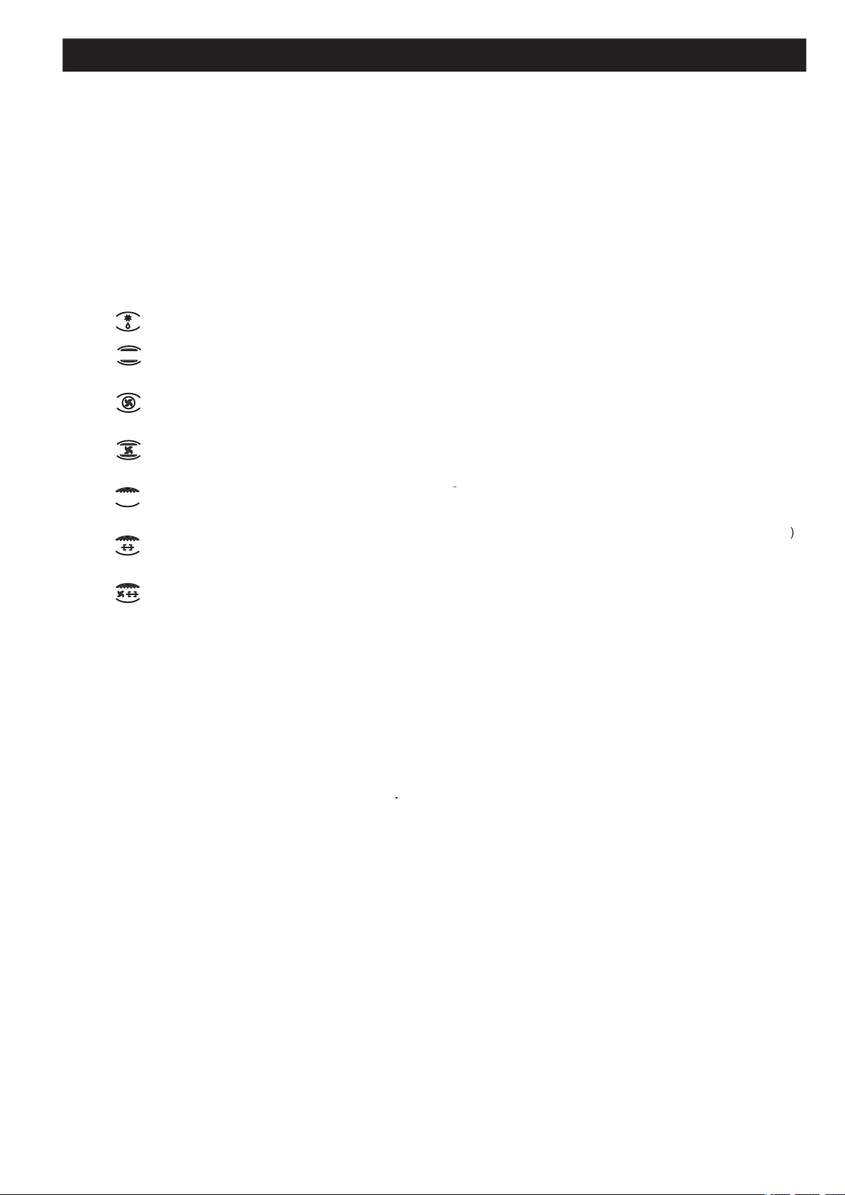
Secondo i modelli, le cucine possono avere inoltre:
- Dispositivo di sicurezza per uno o più bruciatori del piano di
cottura.
- Accensione elettrica ai bruciatori superiori
- Accensione elettrica ai bruciatori forno e grill.
- Termostato per forno.
- Illuminazione elettrica nel forno.
- Girarrosto.
- Contaminuti meccanico.
- Timer elettronico
targhetta è visibile aprendo il vano scaldapiatti (se esiste) oppure
è situato nello schienale della cucina.Una copia della targhetta
è incollata sulla copertina del libretto.
ci.
Queste informazioni completano ed arricchiscono quelle ripor-
tate nella scheda tecnica ( stiker adesivo ) assieme al libretto
...........................................
.......................................................................
3 - 5
Aerazione del locale
................................................................
3
...............................................................................
3
....................................................................
3
.............................................................
3
...............................................
3
Collegamento gas
....................................................................
3
Adattamento ai diversi gas
......................................................
4
Sostituzione iniettori
................................................................
4
Come si smonta il grill elettrico
................................................
4
................................................................
4
Allacciamento elettrico
.............................................................
4
Accensione elettrica
................................................................
5
...........................................................
5
.......................................................................
5 - 9
Aerazione del locale
................................................................
5
Accensione dei bruciatori
........................................................
5
Accensione del forno a gas
.....................................................
5
Accensione del grill a gas
........................................................
5
...........................................................
5
Accensione elettrica
................................................................
5
......................................................
5
......................................................................
6
..........................................................................
6
......................................................................
6
....................................
7
.................................
7
.......................................................
7
.............................................
7
.........................................................................
7
.............................................................
7
.................................................................
8
...............................................
7
...........................................................
8
.........................................
8
Consigli e avvertenze
.............................................................
8
..................................................
9
...........................................
9
..........................................................................
26 - 28
one
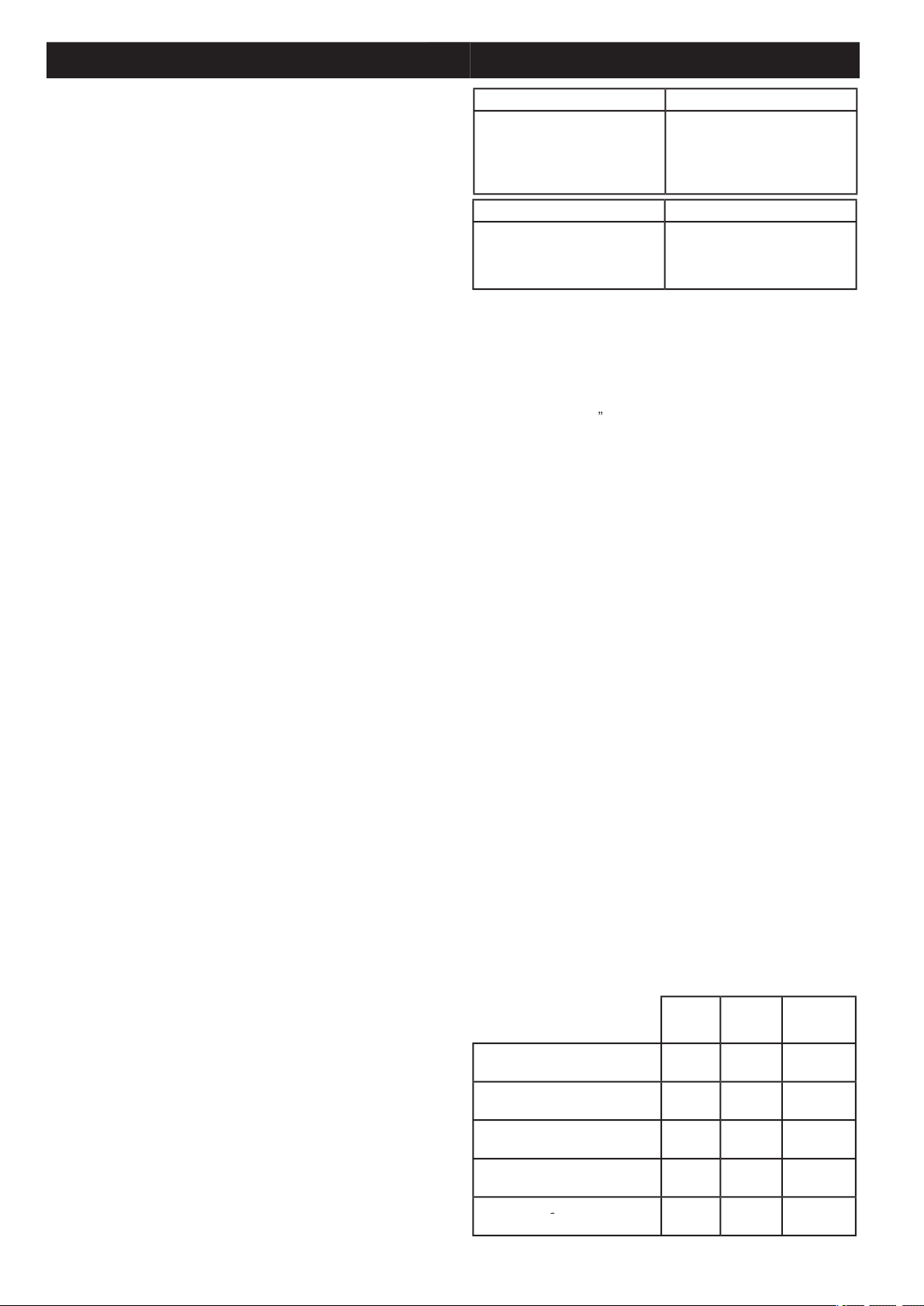
Tempo im
piegato per cottura carico
56.6
58.5
Tempo impiegato per cottura carico
81.6
75.9
Consumo posizione stand-by in watt
Superfi c
o di cottura
cm
2
2877
2729
2729
Cucina 90 x 60
Altezza al piano di lavoro
Altezza a coperchio alzato
cm 85
cm 141
cm 59
cm 100
cm 90
Altezza
Volume
cm 75
cm 48
cm 33
Dati tecnici
Page 3
3
Installazione
IT
dovrà attenersi alle norme di installazione vigenti.
dell’apparecchio siano compatibili. Le condizioni di regolazione
di questo apparecchio sono scritte sulla targhetta in copertina.
Questo apparecchio non è raccordato ad un dispositivo di eva-
cuazione dei prodotti di combustione. Dovrà essere installato e
Questo apparecchio può essere installato e funzionare solo in
- Per l’Italia: UNI 7129 o 7131. Inoltre per gli apparecchi privi del
dispositivo di sicurezza per l’assenza di fi amma sul piano di
ambienti con ventilazione maggiorata secondo il D.M. 1 Aprile
AERAZIONE DEL LOCALE
ventilazione corretta.In particolare l’affl usso di aria necessaria
3
/h per cia-
scun kW di portata nominale installato.
carta, ecc.).La cucina può essere installata libera oppure tra due
e che non possono essere più alte del piano di lavoro.
)
vamente sugli angoli posteriori e anteriori della cucina. Agendo
sui piedini è possibile una regolazione dell’apparecchiatura in
altezza, per un preciso accostamento al mobile, per un livel-
ciali molle bilanciate. Esse sono inserite nella cerniera al fi ne di
consentire la chiusura dolce e regolare del coperchio.
- Aprire completamente la porta.
- fare leva delicatamente con un manico di una posata nelle
due rientranze ricavate nella controporta nella parte inferiore
- il vetro liberato dalla sede delle due mollette, potrà essere sfi lato
dalla nicchia allog
gio vetr
o posta in alto della controporta.
-
fi
ssare la maniglia a corredo mediante le 2 viti in dotazione.
Vedi fi g. 4
Terminato il montaggio della maniglia, rifare le medesime ope-
- inserire il vetro nella nicchia alloggio vetro, posta in alto della
controporta.
- premere delicatamente il vetro nella parte inferiore affi nché i
due perni
fori di fi ssaggio.
- assicurarsi che la porta si richiuda completamente .
COLLEGAMENTO ALL’ALIMENTAZIONE DEL GAS
- A (norma d’installazione UNI 7129 paragrafo 2.5.2.3).
gas con il quale sarà alimentata. In caso contrario eseguire la
trasformazione indicata nel paragrafo “Adattamento ai diversi
gas”. Il collegamento dell’apparecchio si fa a destra. Se il tubo
deve passare dietro, deve rimanere nella parte bassa della
cucina. In tale zona la temperatura è circa 50°C.
-
(vedi Figura 5 disegno A):
Il raccordo si effettua con un tubo conforme alle norme nazio-
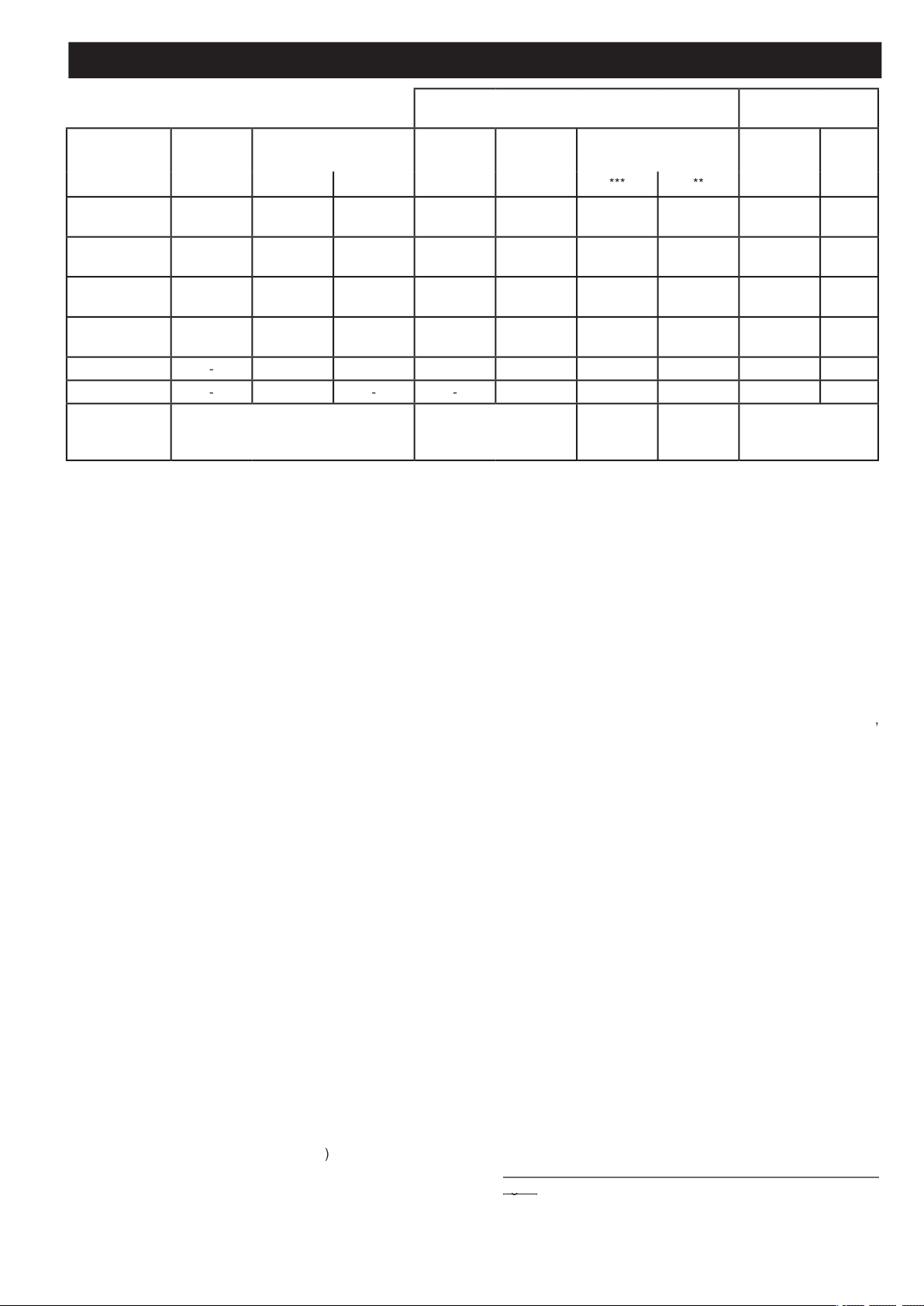
*
A 15°C e 1013 mbar-gas secco
** Propano P.C.S. = 50,37 MJ/Kg
*** Butano P.C.S. = 49,47 MJ/Kg
Naturale P.C.S. = 37,78 MJ/m
3
Città P.C.S. = 15,87 MJ/m
3
T
abella 1
G
as liquido G30-G31
Gas naturale G20
By-pass
1/100
Ugello
1/100
g/h
(mm)
(mm)
2.80
0,68
83
204
200
267
Semi Rapido
76
0.453265
97
Ausiliario
51
0.4032507395
Quadri Corona
3.407096
247
243
324
5.0070364
357
476
Grill 3.8 kW
3.80
277
272
362
alimentazione
28-30
203520
25
Page 4

4
IT Installazione
-
(vedi Figura 5
disegno B e C):
Si effettua con un tubo in gomma che porta il marchio di con-
formità alla norma in vigore. Il tubo deve essere sostituito alla
data indicata e deve essere assicurato alle due estremità per
deve essere assolutamente accessibile per il controllo del suo
stato su tutta la sua lunghezza.
- Dopo l’installazione verifi care la buona tenuta dei raccordi.
- Per il funzionamento con B/P verifi care che la pressione del gas
sia conforme a quanto indicato sulla targhetta matricolare.
- Impiegare solo tubi fl essibili metallici (UNI CIG 9891) o in
gomma (UNI CIG 7140) normalizzati.
- Il regolatore di pressione per GPL deve essere conforme a
- Il raccordo della rampa è conforme a ISO 228-1.
- Evitare curve brusche nel tubo e tenerlo opportunamente
scostato da pareti calde.
ADATTAMENTO AI DIVERSI GAS
Qualora la cucina non fosse già predisposta per funzionare con
seguente ordine:
- Sostituzione degli iniettori (consultando il quadro a pag. 3);
- regolazione dell’aria primaria;
- regolazione dei “minimi”.
colare l’indicazione del gas di nuova regolazione.
- Togliere la griglia, gli spartifi amma (
A
) e i bruciatori (
);
- svitare e togliere l’iniettore situato nel fondo di ciascun
C
);
- sostituire l’iniettore conformemente alla tabella di pag. 3,
avvitare e stringere a fondo;
- verifi care la tenuta del gas con prodotti cercafughe;
- riposizionare i bruciatori, gli spartifi amma e la griglia.
- Allentare la vite di fi ssaggio del fondo forno;
- togliere il fondo forno sollevandolo;
- asportare il bruciatore forno dopo aver tolto la vite che lo fi ssa
a
) ;
- sostituire l’iniettore utilizzando una chiave a tubo da 7 mm.
GRILL (fi g. 7b)
- Asportare il bruciatore dopo aver tolto le due viti che lo fi ssano
) ;
- sostituire l’iniettore utilizzando una chiave a tubo da 7 mm.
- Non serrare mai esageratamente gli iniettori;
- a sostituzione avvenuta, controllare la tenuta gas di tutti gli
con rubinetto aperto e iniettore otturato, indica una perdita di
gas.
COME SI SMONTA IL GRILL ELETTRICO ( Fig. 7 C )
- svitare le viti di fi ssaggio
a
) e
)
- staccare i collegamenti elettrici sotto lo schienale carter.
all’interno (vi si accede introducendo un piccolo cacciavite nel-
Se la cucina deve funzionare con gas naturale si procede nel
seguente modo per entrambi i tipi di rubinetto:
- Accendere il bruciatore con la fi amma al max.;
- sfi lare la manopola, per semplice trazione, senza fare leva sul
cruscotto, che si potrebbe danneggiare;
- accedere al by-pass con un piccolo cacciavite e svitarlo di 3
giri circa (ruotando il cacciavite in senso antiorario);
- ruotare ulteriormente l’astina del rubinetto, in senso antiorario,
fi no all’arresto: la fi amma si presenterà al max.;
- riavvitare molto lentamente il by-pass, senza spingere assial-
anche con moderate correnti d’aria.
Qualora invece la cucina debba funzionare con gas naturale si
- Togliere il fondo del forno (spingendolo verso lo schienale ed
alzandolo);
- accendere il bruciatore del forno posizionando l’indice della
- chiudere la porta del forno;
- accedere al by-pass del termostato (vedi fi g. 10);
- svitare il by-pass del termostato di circa 3 giri;
- trascorsi 5 o 6 minuti, portare l’indice della manopola sulla
- riavvitare lentamente il by-pass osservando l’abbassarsi della
fi amma attraverso l’oblò della porta (chiusa) fi no a che il dardo
della fi amma si presenta lungo 4 mm circa. Si raccomanda di
Essa deve risultare stabile anche con movimento deciso della
- spegnere il bruciatore, rimontare il fondo forno.
ALLACCIAMENTO ALLA RETE ELETTRICA
- la tensione in rete corrisponda a quella indicata sulla targhetta
- la presa di “terra” sia effi ciente.
tore deve prevedere un interruttore con una distanza di apertura
dei contatti uguale o superiore a 3 mm.
Se l’apparecchio è equipaggiato di un cavo senza spina, la spina
da utilizzare è di tipo normalizzato e tenere conto che:
- cavo verde-giallo deve essere utilizzato per il collegamento a
terra;
- cavo blu per il neutro;
- cavo marrone per la fase;
- il cavo non deve entrare in contatto con pareti calde che siano
superiori a 75°C;
- in caso di sostituzione del cavo, deve essere di tipo HO5RR-
2)
- in caso l’apparecchio sia fornito senza cavo, utilizzare cavo
tipo HO5RR-F o H05V2V2-F con sezione adeguata (vedere
schemi in fi g. 2).
il costruttore declina ogni responsabilità per
danni dovuti all’assenza del rispetto delle regolamentazioni e
delle norme in vigore.
Si raccomanda di controllare che il collegamento a terra del-
Page 5

5
Installazione
IT
Se non scocca la scintilla è bene non insistere: si potrebbe
danneggiare il generatore. Possibili cause di funzionamento
anomalo o ineffi ciente:
- candela umida, incrostata o rotta;
- distanza non corretta elettrodo-bruciatore;
- fi lo conduttore della candela rotto o privo di guaina;
- scintilla che scarica a massa (in altre parti della cucina);
- generatore o microinterruttore danneggiati;
- accumulo di aria nelle tubazioni (specie dopo lunga inattività
della cucina);
- miscela aria-gas non corretta (cattiva carburazione).
7a,7b,8a,8b.
- accendere il bruciatore e lasciarlo funzionare per 3 minuti
circa;
- spegnere il bruciatore riportando la manopola sulla posizione
di chiusura (
);
- trascorsi 90 secondi per i bruciatori del piano, 60 secondi per
- abbandonare la manopola in questa posizione ed accostare un
fi ammifero acceso al bruciatore: NON DEVE ACCENDERSI.
Tempo occorrente per eccitare il magnete durante l’accensione:
Tempo di intervento automatico, dopo lo spegnimento della
fi amma: non oltre 90 secon-
di per i bruciatori del piano; non oltre 60 secondi per i bruciatori
forno e grill.
- Qualunque intervento tecnico all’interno della cucina deve
essere preceduto dal disinserimento della spina elettrica e
dalla chiusura del rubinetto del gas.
- Le verifi che di tenuta sul circuito gas non devono essere ese-
guite con l’uso di fi amme. Se non si dispone di uno specifi co
dispositivo di controllo, si può utilizzare schiuma od acqua
abbondantemente saponata.
- Richiudendo il piano di lavoro curare che i fi li elettrici delle
candele (se vi sono) non si trovino in prossimità degli iniettori,
COME SI USA LA CUCINA
AERAZIONE DEL LOCALE
di calore e umidità nel locale in cui è installato. Vigilare al fi ne di
assicurare una buona aerazione della cucina: mantenere aperti
gli orifi zi di aerazione naturale, oppure installare una cappa di
aspirazione forzata.
o un’aerazione più effi cace, aumentando per esempio la potenza
della ventilazione forzata.
ACCENSIONE DEI BRUCIATORI DEL PIANO Dl LAVORO
- Premere e ruotare la manopola in senso antiorario fi no al sim-
segnato sul cruscotto (posizione di fi amma al max.);
- nel contempo accostare un fi ammifero acceso alla testa del
- volendo una riduzione della fi amma, ruotare ulteriormente la
simbolo
(posizione di fi amma al min.).
- Premere e ruotare in senso antiorario fi no al simbolo
sul
cruscotto (posizione fi amma al max.);
- accostare un fi ammifero acceso al bruciatore e mantenere la
- abbandonare quindi la manopola ed accertarsi che il bruciatore
ACCENSIONE DEL BRUCIATORE FORNO
- Aprire la porta del forno;
- premere e ruotare la manopola in senso antiorario fi no alla
- accostare un fi ammifero acceso al foro centrale del fondo forno
e premere a fondo la manopola (vedi fi g. 11);
- verifi care l’avvenuta accensione attraverso i due fori laterali
del fondo mantenendo sempre premuta la manopola;
- dopo 10 secondi circa, abbandonare la manopola ed accertarsi
che il bruciatore sia rimasto acceso. In caso contrario, ripetere
ACCENSIONE DEL BRUCIATORE GRILL
- Collocare la protezione manopole come indicato in fi g. 14;
- premere e ruotare la manopola del forno verso destra, fi no
all’arresto;
- accostare un fi ammifero acceso al tubo forato del bruciatore
e premere a fondo la manopola (vedi fi g. 12);
- verifi care l’avvenuta accensione del bruciatore mantenendo
sempre premuta la manopola;
- dopo 10 secondi circa, abbandonare la manopola ed accertarsi
che il bruciatore sia rimasto acceso. In caso contrario, ripetere
fuoriuscita di gas incombusto: dallo spegnimento della fi amma,
e grill o 90 secondi per i bruciatori del piano di cottura.
Vale interamente quanto detto sopra, salvo che l’uso del fi ammi-
fero è sostituito da una scintilla che si ottiene premendo, anche
Per l’utente
Page 6
6
Per l’utente
IT
Qualora l’accensione elettrica si rilevasse diffi coltosa per deter-
- Per le cucine munite di accensione elettrica ai bruciatori forno
e grill, è
accendere questi bruciatori con la porta
del forno totalmente aperta;
- Durante l’accensione dei bruciatori del forno e del grill che sono
azionato per più di 10 secondi.
Se dopo questi 10 secondi il bruciatore non è acceso, smettere
di agire sul dispositivo, lasciando la porta aperta e attendere
almeno un minuto prima di riprovare ad accendere il bruciatore.
Qualora il malfunzionamento del dispositivo di accensione do-
vesse ripetersi, provvedere all’accensione manuale e chiamare
AVVERTENZE:
- Se, dopo una certa inattività della cucina, l’accensione risul-
tasse diffi coltosa, è un fatto normale. Basteranno tuttavia
espulsa;
- in ogni caso, bisogna evitare una esagerata erogazione di gas
tempo relativamente breve, si ripete l’operazione dopo avere
(
)
- alla prima accensione del forno e del grill si potrà avvertire un
caratteristico odore e fumo uscire dalla bocca del forno stesso.
Ciò è dovuto al trattamento delle superfi ci ed a residui oleosi
sui bruciatori.
COME SI USANO I FUOCHI DEL PIANO DI COTTURA
Consigliamo:
- per bruciatore ausiliario = recipiente di almeno cm. 8 utilizzando
- per bruciatore semirapido = recipiente di
almeno cm. 14
- per bruciatore rapido e tripla corona = recipiente di almeno
cm. 22
fra il simbolo di fi amma al massimo
e la posizione di chiusura
(
).
COME SI USA IL FORNO A GAS
- Dopo aver acceso il bruciatore, lasciare riscaldare il forno per
- predisporre la vivanda da cuocere in una teglia di normale
commercio, e appoggiarla sulla griglia cromata;
- introdurre il tutto nel forno utilizzando di preferenza il gradino più
alto possibile e portare l’indice della manopola sulla posizione
desiderata;
- la fase di cottura può essere osservata attraverso l’oblò della
frequentemente la porta stessa, salvo che per oleare o ungere
a)
con bruciatore forno 5kW:
- con la manopola in posizione di "massimo"
= 280°C
- con la manopola in posizione di "minimo"
= 160°C
)
con bruciatore forno 3,3kW:
- con la manopola in posizione di "massimo"
= 275°C
- con la manopola in posizione di "minimo"
= 160°C
simboli di "massimo"
e di chiusura (
).
AVVERTENZA IMPORTANTE
COME SI USA IL GRILL A GAS
- collocare la protezione manopole (vedi fi g. 14);
- accendere il bruciatore ed attendere qualche minuto per dare
tempo al bruciatore di riscaldarsi;
- posare la vivanda sulla griglia;
- introdurre il tutto sul gradino più alto del forno;
- collocare la leccarda sul gradino inferiore;
- richiudere dolcemente la porta appoggiandola alla protezione
- dopo qualche minuto rivoltare la vivanda per esporre l’altro
al tipo di vivanda ed al gusto personale dell’ utente).
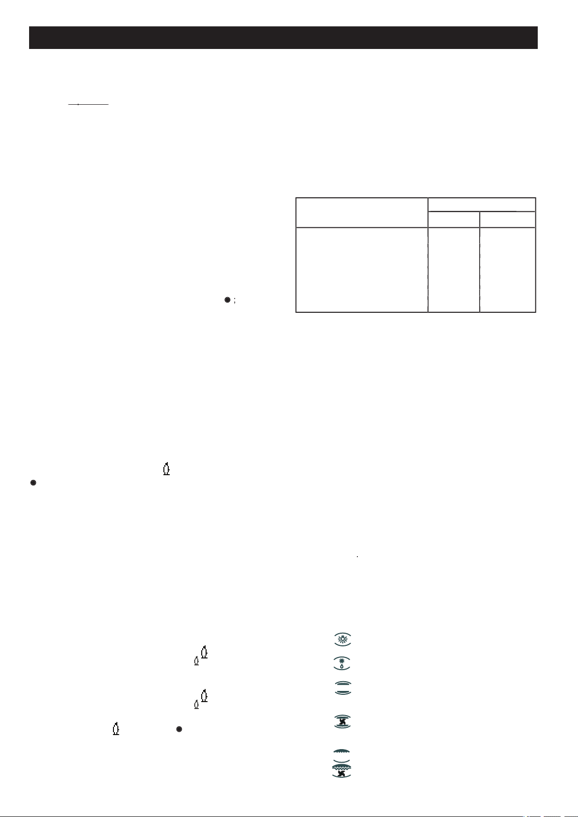
Vedere tabella " Alimenti da grigliare"
Alimenti da
Tempo in minuti
grigliare
2° Lato
Carni basse o sottili 6 4
Carni moderatamente alte 8 5
Salsicce 12 10
Toast 5 2
dal forno.
eventuali residui di olio sul bruciatore siano totalmente bruciati. Il
grill deve essere usato solo alla sua portata calorica nominale.
ATTENZIONE
COME SI USA IL GRILL ELETTRICO
CON FORNO
A GAS
- accendere resistenza grill;
- posare la vivanda sulla griglia;
- introdurre il tutto sul gradino più alto del forno;
- collocare la leccarda sul gradino inferiore;
- richiudere dolcemente la porta ;
- dopo qualche minuto rivoltare la vivanda per esporre l’altro
al tipo di vivanda ed al gusto personale dell’ utente).
Vedere tabella " Alimenti da grigliare"
orario fi no al simbolo del grill sul cruscotto.
della resistenza
COTTURA
Grazie ai diversi elementi riscaldanti comandati da un selettore
e regolati da un termostato,
e girando la manopola in senso orario si hanno le seguenti
- simbolo
accesa anche con l’indice della manopola su tutte le posizioni
- simbolo
- simbolo
termostato.
- simbolo
del termostato.
- simbolo
- simbolo
del forno viene regolata mediante la manopola del termostato.
Tempo in minuti
Page 7
7
Per l’utenteIT
forno per 10 minuti almeno.
Grazie ai diversi elementi riscaldanti comandati da un selettore e
a)
Propagazione forzata del calore (forno ventilato).
Propagazione spontanea del calore (convezione o forno
statico).
c)
Raggi infrarossi (grill).
selezione in senso orario si hanno le seguenti posizioni:
- simbolo
- simbolo
termostato.
- simbolo
del termostato.
- simbolo
del termostato.
- simbolo
- simbolo
- simbolo
diante la manopola del termostato. Il girarrosto è in funzione.
termostato. Prima di introdurre le vivande da cuocere, si lasci
COME SI USA IL GRILL ELETTRICO
CON FORNO ELET-
TRICO
- Per soli modelli con "Forno Elettrico " comandati da due
a porta chiusa, senza l'uso della protezione manopola
Con la grigliatura a porta chiusa, non si de
vono utilizzare
temperature superiori a 200°C.
COME SI USA IL GIRARROSTO
a)
Con grigliatura a porta aperta.
- collocare la protezione manopole come indicato in fi gura 14 ;
- infi lzare la carne da cuocere nello schidione e fi ssarla al centro
a mezzo dei due forchettoni;
- infi lare la punta dello schidione nel mozzo del rinvio situato nel
telaio (vedi fi g. 15);
- privare lo schidione della sua impugnatura
- collocare il telaio supporto schidione nel gradino centrale del
forno infi lando contemporaneamente l’albero del rinvio nel
- collocare la leccarda sul gradino più basso del forno avendo
cura di versarvi un po’ d’ acqua;
- accendere il bruciatore del grill;
- richiudere dolcemente la porta appoggiandola alla protezione
- avviare il motorino premendo l’apposito interruttore posto sul
- ungere la carne di tanto in tanto. A cottura avvenuta, sfi lare
- come sopra, senza l'utilizzo della protezione manopola indicato
ATTENZIONE
- Nei modelli di cucine a gas è previsto un interruttore circola-
- premendo sull’interruttore si accende contemporaneamente la
A RICHIESTA KIT MULTISPIEDO
- E’ possibile equipaggiare il vostro girarrosto (che prevede 2
forchettoni) di un ulteriore meccanismo che permette di otte-
- La richiesta va inoltrata al vostro rivenditore dietro pagamen-
to.
- Estrarre i forchettoni standard.
- posizionare e fi ssare le fl ange sullo schidione come da fi gura
- infi lzare le vivande sugli spiedini.
- inserire gli spiedini sulle fl ange come da fi gura 17.
ATTENZIONE
)
al tempo desiderato.
Trascorso il tempo prestabilito, interviene un segnale acustico
che cessa automaticamente. Il contaminuti, all’atto del segnale
acustico, non interrompe il funzionamento del forno.
COME SI USA IL PROGRAMMATORE ELETTRONICO (fi g.
Consente di programmare l’ora di inizio e la durata di cottura
Se la cottura inoltre non necessita di controllo a vista, essa può
avvenire anche in assenza dell’utente.
Al momento dell’installazione o dopo un periodo di mancanza
dell’alimentazione elettrica, il visualizzatore lampeggia; è quindi
- Premendo contemporaneamente 2 tasti (DURATA COTTURA,
tale operazione vengono cancellati eventuali programmi
TASTI “+” E “-”
- Azionando i tasti “+” o “-” il tempo aumenta o decresce ad
esercitata sul tasto.
- Azionare il tasto MANUALE: il simbolo AUTO si spegne
agendo sulle manopole del termostato forno e del selettore
secondo le istruzioni del manuale.
- Facciamo un esempio: sono le ore 9.25; si desidera che il forno
entri in funzione alle ore 11.00 e che termini la cottura alle ore
Page 8

8
Per l’utenteIT
- Premere il tasto DURATA COTTURA ed entro 5 secondi
aggiustare l’indicazione col tasto “-”. I simboli AUTO e
- Premere il tasto FINE COTTURA ed entro 5 secondi premere
si spegne, mentre il simbolo AUTO rimane illuminato
- Posizionare la manopola del termostato forno sulla temperatura
desiderata, ed il selettore sul tipo di cottura prescelto; la
spia rossa si illumina, la luce del forno di accende ed il
si illumina.
- Al termine della cottura (ore 12.00) il simbolo AUTO lampeggia
della fi ne cottura: per interromperlo è necessario premere un
- Posizionare quindi le manopole del termostato forno e del
selettore sulla posizione di spento.
- Facciamo un esempio: sono le 11.35 e si desidera che il
forno rimanga in funzione per 25 minuti a partire da questo
- Premere il tasto DURATA COTTURA ed entro 5 secondi
aggiustare l’indicazione con il tasto “-”. I simboli AUTO e
- Posizionare la manopola del termostato forno sulla temperatura
desiderata, ed il selettore sul tipo di cottura prescelta; la spia
- Dopo 25 minuti il forno ed il simbolo PENTOLA si spengono,
della fi ne cottura: per interromperlo è necessario premere un
- Posizionare quindi le manopole del termostato forno e del
selettore sulla posizione di spento.
- Premere il tasto CONTAMINUTI e selezionare il tempo
desiderato mediante il tasto “+” o “-”.
- Durante il funzionamento del contaminuti si illumina il simbolo
CAMPANA.
- Al termine del tempo impostato si mette in funzione il segnale
acustico e il simbolo CAMPANA si spegne.
- Il segnale acustico si mette in funzione al termine di una
- Per interromperlo prima si dovrà premere un tasto qualsiasi.
- Azionando il tasto “-” senza avere prima selezionato una fun-
zione è possibile cambiare la frequenza del segnale acustico.
Si può scegliere fi no a 3 diversi tipi di segnale. Il segnale se-
“-”.
- Il programma ha inizio dopo ca. 4 secondi dall’impostazione.
- In qualsiasi momento è possibile controllare il programma
- Esempio: alle ore 12.15 si impostano 30 minuti di DURATA
COTTURA e si imposta il tempo di FINE COTTURA alle ore
- L’errore di impostazione puo essere corretto variando la
durata o il tempo di fi ne cottura, oppure premendo il pulsante
- In presenza di un errore di impostazione il forno non viene
ANNULLAMENTO Dl UN PROGRAMMA
- Si può cancellare un programma premendo il tasto di DURATA
COTTURA e di seguito il tasto “-” fi no a che sul display non
compare l’indicazione 0.00.
ALLA FINE Dl OGNI COTTURA PROGRAMMATA SI
CONSIGLIA Dl PREMERE IL TASTO
COME SI USANO GLI ACCESSORI DEL FORNO
- La griglia del forno serve a supportare teglie di commercio
al grill.
- La leccarda serve unicamente per raccogliere i sughi colati dalle
vivande. Non deve mai essere usata come piatto di cottura.
- Se si effettua la cottura a forno ventilato, è possibile caricare
contemporaneamente due griglie.
Come si smonta il vetro porta forno.
- aprire completamente la porta.
- fare leva delicatamente con un manico di una posata nelle
due rientranze ricavate nella controporta nella parte inferiore
- il vetro liberato dalla sede delle due mollette, potrà essere sfi lato
dalla nicchia allog
gio vetr
o posta in alto della controporta.
Terminata la pulizia, rifare le medesime operazioni in senso
contrario.
- inserire il vetro nella nicchia alloggio vetro, posta in alto della
controporta.
- premere delicatamente il vetro nella parte inferiore affi nché i
due perni
fori di fi ssaggio.
- assicurarsi che la porta si richiuda completamente .
CONSIGLI ED AVVERTENZE DI ORDINE GENERALE
- Qualsiasi intervento, all’interno del forno o ove vi sia la possi-
sempre dal disinnesco dell’alimentazione elettrica.
- Non utilizzare il vano scaldapiatti come ripostiglio per liquidi
- Controllare frequentemente il tubo di raccordo in gomma curare
che sia suffi cientemente lontano da pareti calde, che non abbia
curve brusche o strozzature, e che sia in buone condizioni. Il
tubo deve essere sostituito al più tardi alla data indicata e deve
essere assicurato alle due estremità per mezzo di fascette
stringitubo normalizzate.
- Nel caso la rotazione dei rubinetti divenga diffi coltosa nel
tempo, contattare il Servizio Assistenza Tecnica.
- Le parti smaltate o cromate si lavano con acqua tiepida sapo-
gli spartifi amma, invece, si può usare anche uno spazzolino
- Non usare abrasivi per pulire parti smaltate o cromate.
- Lavando il piano di cottura, evitare inondazioni. Fare atten-
zione che non entri acqua o altro nei fori di alloggiamento dei
- Le candele per l’accensione elettrica devono essere mantenute
vi sono stati gocciolamenti o trabocchi dalle pentole.
scheggiarsi o rompersi.
- Non urtare le parti smaltate e le candele di accensione (se vi
sono).
- Quando la cucina non è in servizio, è buona norma chiudere
- Non alzare mai la cucina tenendola per la maniglia porta for-
- Un eventuale surriscaldamento eccessivo sulle pareti ester-
Page 9
9
dell’alimentazione sarà spontanea, dopo che la temperatura
esterna al forno sarà rientrata entro i limiti di accettabilità. Si
tivo è provocato da una condizione anormale di funzionamento
del forno). Occorre quindi interpellare il tecnico.
- Alla prima accensione del forno e del grill si potrà avvertire un
caratteristico odore e fumo uscire dalla bocca del forno stes-
so. Ciò è dovuto al trattamento delle superfi cie. Si consiglia
di lasciare funzionare il forno a vuoto prima di introdurre delle
vivande.
- Non usare la maniglia per spostare la cucina.
Si declina ogni responsabilità per danni a cose o a persone
derivanti da una cattiva installazione o da un uso non corretto
della cucina.
di gas o di corrente, interpellare il tecnico senza alcun
Fig. A
Questa nota informativa è rivolta esclusivamente ai possessori
Questa nota informativa è rivolta esclusivamente ai possessori
di apparecchi che presentano il simbolo di (Fig. A) nell’etichetta
di apparecchi che presentano il simbolo di (Fig. A) nell’etichetta
adesiva riportante i dati tecnici, applicata sul prodotto stesso
adesiva riportante i dati tecnici, applicata sul prodotto stesso
Questo simbolo indica che il prodotto è classifi cato ,secondo
ed è conforme alla Direttiva EU 2002/96/EC (RAEE) quindi,
alla fi ne della propria vita utile, dovrà obbligatoriamente essere
trattato separatamente dai rifi uti domestici, consegnandolo
gratuitamente in un centro di raccolta differenziata per appa-
al rivenditore al momento dell’acquisto di una nuova apparec-
chiatura equivalente.
fi ne vita alle appropriate strutture di raccolta, pena le sanzioni
smaltimento ambientalmente compatibile contribuisce ad evitare
disponibili, rivolgersi al servizio locale di smaltimento rifi uti, o al
compatibile sia direttamente sia partecipando ad un sistema
collettivo
Per l’utente
IT
tatto con alimenti.
gli alimenti, in questo prodotto, sono conformi a quanto prescritto
dal regolamento europeo n° 1935/2004.
All’interno della cavità del forno gli alimenti potrebbero venire
a contatto con: griglie forno, leccarde, piastre pasticcere, vetro
forno,
Sul piano di lavoro con: griglie, bruciatori e piano lavoro me-
desimo.
Page 10

Technical data and specifi cations.....................................
Ventilation
.........................................................................
...............................................................
Gas connection
Adapting to different types of gas
.....................................
...............................................................
Safety device
....................................................................
Ventilation
...........................................................
Safety device
....................................................................
...........................................................
................................................
oven with 6 cooking programs
...........................................................
Oven light / rotisserie switch
..................................................................
......................................................
................................................
............................................
forno
6
Advice and precautions
....................................................
.........................
6
.......................................................................
26 - 28
Thank you for choosing one of our quality products, capable of
giving you the very best service. To make full use of its perfor-
appliance carefully. The Manufacturer declines all responsibility
for injury or damage caused by poor installation or improper use
of the appliance.
- To ensure its appliances are always at the state of the art,
and/or to allow constant improvement in quality, the manufac-
turer reserves the right to make modifi cations without notice,
although without creating diffi culties for users.
- When ordering spare parts, inform your dealer of the model
or on the back of the cooker.
- APPLIANCE COMPLYING WITH THE FOLLOWING DIREC-
TIVES:
- 2006/95/EC Low Voltage (replaces 73/23/EEC and subse
quent amendments)
- EEC 73/23 and 93/88
- EEC 89/336 (radio-frequency inter-ference)
-
tact with food
)
- EEC 40/2002
- EEC 92/75
- 2002/96/EC (WEEE)
Introduction
Index
GB
grill 2.4 kW
oven light 15 W
Cat.: see nameplate on cover; Class 1 or 2.1Type “X” cookers
All models are equipped with safety device for oven and grill
- Safety device for one or more hob burners
- Electric ignition on top burners
- Electric ignition on oven and grill burners
- Self-cleaning enamelled liners
- Oven thermostat (or tap)
- Electric oven lighting
- Rotisserie
- Grill burner
- Mechanical timer
- Electronic timer
of this manual.
The electrical power is stated on the nameplate visible inside
the warming compartment (if present) or on the back of the
cooker.
A copy of the nameplate is glued to the cover of this manual (for
gas or gas-electric products only).
of electric ovens.
This information completes and expands on the fi gures pro-
vided on the technical data sticker supplied with the instruc-
tion manual.
Ove
96 N
static
Oven
96N fan
Oven 96 N
Time required to cook a normal load
conventional mode in minutes.
56.6
58.5
Time required to cook a normal load
81.6
75.9
setting in Watts
cm
2877
2729
2729
Cookers 90 x 60
Height with lid raised
Depth with door closed
Depth with door open
Width
cm 85
cm 141
cm 59
cm 100
cm 90
O
ven grill multifunction
Width
Volume
cm 75
cm 48
cm 33
Page 11

GB
* At 15°C and 1013 mbar-dry gas
** Propane P.C.S. = 50,37 MJ/Kg G 31
*** Butane P.C.S. = 49,47 MJ/Kg G 30
Natural P.C.S. = 37,78 MJ/
3
G 20
City P.C.S. = 15,87 MJ/
3
G 110
Installation
The appliance must be installed by qualifi ed staff working in ac-
cordance with the regulations in force.Before installing, ensure
that the appliance is correctly preset for the local distribution
conditions (gas type and pressure).The presettings of this appli-
ance are indicated on the nameplate shown on the cover.
This appliance is not connected to a fl ue gas extractor device. It
tions in force.This appliance may only be installed and may only
operate in rooms permanently ventilated in accordance with
VENTILATION
The rooms in which gas appliances are installed must be well
ventilated in order to allow correct gas combustion and ventila-
tion.The air fl ow necessary for combustion is at least 2 m
3
/h for
each kW of rated power.
the chrome-plated and stainless steel parts, from the cooker.
aged by heat (wood, linoleum, paper, etc.).
The cooker may be installed alone or between two kitchen units;
of 100 degrees C and they must not be higher than the cooker
Cookers are equipped with adjustable feet to be screwed into
their front and rear corners respectively. The feet allow the height
of the appliance to be adjusted, in order to set it fl ush with the
adjoining unit, to level it with other worktops and to ensure even
distribution of the liquids in pans. See fi g. 3.
smooth, gentle lid closure.
- fully open the door.
- apply gentle leverage with the handle of a fork or spoon in
the two recesses in the bottom of the inside of the door, one
at a time.
- once released from the two springs, the glass can be ex-
tracted from the seat in the top of the inside of the door.
-
After fi tting oven door handle, repeat the same procedure in
- fi t the glass into its seat in the top of the inside of the door.
- press gently on the bottom of the glass so that the two pins,
with silicone on the inside, fi t into their holes.
- make sure that the door closes completely.
CONNECTING TO THE GAS SUPPLY
to be used. Otherwise, make the conversion as described in the
section headed “Adapting to different gas types”. The connec-
tion is on the right; if the pipe has to pass behind the cooker,
degrees C.
-
(see Figure 5, diagram D):
The connection to the mains gas supply may be made using
a rigid metal pipe (D). Remove the hose connector and screw
the rigid union onto the threaded connection of the gas train.
The union for rigid connection is amongst the cooker acces-
sories.
-
Connection using a rubber hose
Connection using a rubber hose
(see Figure 5, diagrams B and
C):
Connect a rubber hose carrying the conformity mark currently
the date indicated, and must be secured at both ends using
standard hose clamps. It must be absolutely accessible to allow
-
Connection using a metal hose
Connection using a metal hose
(see Figure 5, diagram D):
Make the connection using a hose which complies with national
standards, screwing it onto the connector with a ring seal, which
- After installation, check that all connections are airtight.
T
able 1
G30-G31
Thermal power
By-pass
1/100
Nozzle
1/100
g/h
(mm)
(mm)
2.80
0,68
83
204
200
267
Semi Rapid
76
0.453265
97
Auxiliary
51
0.4032507395
3.407096
247
243
324
Oven
5 kW
5.0070364
357
476
Grill 3.8 kW
3.80
277
272
362
Supply
28-30
20
352025
Page 12

- For operation with butane/propane, check that the gas pressure
- Use only standard rubber hoses. For LPG, use a hose which
complies with the national regulations in force.
- Avoid sharp bends in the pipe and keep it well away from hot
surfaces.
the appliance: ISO 7-1.
ADAPTING TO DIFFERENT TYPES OF GAS
available, it must be converted. Proceed as follows:
- Replace the injectors (see table on page 11);
- regulate the primary air fl ow;
- regulate the minimum settings.
type of gas on the serial number label.
)
- Remove the grid, the burner caps (
A
), and the burners (
);
- Unscrew and remove the injector in the bottom of each injector
C
);
- replace the injector in accordance with the table in page 11
tighten and screw right down;
- check that the system is gas-tight;
- replace the burners, the burner caps and the grid.
- Never over-tighten the injectors;
- after replacing, check that all the injectors are airtight.
- Loose the screw securing the oven bottom;
- remove the oven bottom (push back and raise);
- remove the oven burner, after taking out its fi xing screw;
- replace the injector, using a 7 mm socket wrench.
- Remove the burner after taking out the two screws which secure
- replace the injector using a 7 mm socket wrench.
- Never over-tighten the injectors;
- after replacing, check that all the injectors are airtight.
- to happened substitution, to check the estate of all the injectors
with leak detector products . The appearance of beads of air
with open faucet and clogged injectors, points out a loss of
gas.
)
- undo the fi xing screws
a
) and
) ;
- disconnect the electrical connections underneath the rear
casing.
SETTING HOB BURNER MINIMUM LEVELS
The cooker may be equipped with type A taps, with by-pass
type B taps, with by-pass on the outside on the right (accessed
directly). See fi gure 9.
- Ignite the burner at maximum fl ame;
- pull off the knob, without using a lever against the control panel,
which might be damaged;
- access the by-pass with a small screwdriver and back off by
about 3 turns (turning the screwdriver anti-clockwise);
- turn the tap rod anti-clockwise again until it stops: the burner
will be at maximum fl ame;
- screw the by-pass slowly back in, without pushing the screw-
GB
Installation
driver, until the fl ame has apparently shrunk to 1/4 of the
quite strong draughts.
SETTING OVEN BURNER MINIMUM LEVELS
thermostat by-pass must be screwed right down.
- Remove the oven bottom (push towards the back and raise);
- ignite the oven burner, turning the knob pointer to the maximum
setting;
- shut the oven door;
- access the thermostat by-pass (see fi g. 10);
- back off the thermostat by-pass by about 3 turns;
- after 5 or 6 minutes, turn the knob pointer to the minimum set-
ting;
- slowly re-tighten the by-pass, watching the fl ame decrease
tongue of the fl ame is about 4 mm long. Never keep the fl ame
too low. It must be stable even when the oven door is opened
or closed quickly;
- turn off the burner and replace the oven bottom.
CONNECTING TO THE ELECTRICAL MAINS
- the mains voltage is as indicated on the nameplate;
- the earth connection is in good working order.
- the green-yellow wire must be used for the earth connection;
- the blue wire is the neutral;
- the brown wire is live;
- the lead must never touch hot surfaces over about 75 degrees
C;
- replacement leads must be of type HO5RR-F or H05V2V2-F
of suitable size (see diagrams in fi g. 2).
- if the appliance is supplied without lead, using type HO5RR-F
or H05V2V2-F cable of suitable size (see diagrams in fi g. 2).
due to failure to comply with the regulations and standards in
force. Check that the appliance is correctly connected to the
earth (see diagrams in fi g. 2 at the back of the manual).
The correct gaps between the electrode and the burner are
shown in fi gures 7a,7b,8a,8b,
damage the generator.
- spark plug damp, dirty or broken;
- electrode-burner gap not correct;
- spark plug wire broken or without sheathing;
- spark discharging to earth (to other parts of the cooker);
- generator or microswitch damaged;
- air has built up in the pipes (particularly if the cooker has been
out of use for a long time);
- air-gas mixture incorrect (poor fuel setting).
THE SAFETY DEVICE
The correct gap between the end of the thermocouple sensor
and the burner is shown in fi gures 7a,7b,8a,8b.
To check that the valve is working properly, proceed as fol-
- ignite the burner and leave it to work for about 3 minutes;
- turn off the burner by returning the knob to off position (
);
- after 90 seconds for hob burners, 60 seconds for oven and grill
Page 13

- release the knob in this position and move a burning match
towards the burner; IT MUST NOT IGNITE.
Time needed to excite the magnet during ignition: 10 seconds
approx.
Automatic tripping time, after fl ame has been turned off: not more
than 90 seconds for hob burners; not more than 60 seconds for
oven and grill burners.
- Before doing any work inside the cooker, disconnect the mains
- Never use matches to check the gas circuit for leaks. If a spe-
cifi c control device is not available, foam or very soapy water
can be used.
- When re-closing the hob, check that the electrical wires of the
spark plugs ( if present ) are not close to the injectors, so that
they cannot run across them.
VENTILATION
All gas cooking appliances produce heat and moisture in the
structed or install an extractor hood with fan.
- Press the knob and turn it anti-clockwise until it reaches the
symbol on the control panel (maximum fl ame position);
- at the same time, move a burning match towards the burner
- to reduce the fl ame, turn the knob further in the same direction
symbol (minimum fl ame posi-
tion).
- Press the knob and turn it anti-clockwise until it reaches the
symbol on the control panel (maximum fl ame position);
- move a burning match towards the burner, keeping the knob
- then release the knob and check that the burner remains on.
Otherwise, repeat the operation.
- Open the oven door;
- press the knob and turn it anti-clockwise to the maximum fl ame
- move a burning match towards the hole in the centre of the
oven bottom and press the knob right down (see fi g. 11);
- look through the two holes in the sides of the bottom to check
that the burner has ignited, keeping the knob pressed down;
- after about 10 seconds, release the knob and check that the
- Fit the control knob guard as shown in fi g. 14;
- press the oven knob and turn it to the right until it reaches the
stop;
- move a burning match towards the perforated burner pipe and
- check that the burner has ignited, keeping the knob pressed
down;
- after about 10 seconds, release the knob and check that the
SAFETY DEVICE
are protected if they accidentally go out. If this occurs, the supply
of gas to the burner concerned is automatically cut off, preventing
the hazards deriving from a leak of unburnt gas. The gas supply
grill burners or 90 seconds for the hob burners.
All the above applies, except that the match is no longer re-
quired; a spark is obtained by pressing the button on the control
- For cookers with electric ignition of the oven and grill burners,
ensure the oven door is completely open when these burners
are ignited;
- Do not operate the ignition device for more than 10 seconds
GB
For the user
Installation
Page 14

when igniting the oven and grill burners. If the burner has not
door open and wait one minute before trying again to ignite
the burner. If the ignition device malfunctions again, light the
- Diffi culty in igniting burners is normal if the cooker has been
out of use for some time. The air accumulated in the pipes will
- Never allow too much unburnt gas to fl ow from the burners.
the procedure after returning the knob to the off position (
);
- when the oven and grill are lit for the fi rst time, a smell may be
of the surface treatment and oily residues on the burners.
sizes:
- for auxiliary burners = pans of at least 8 cm using the adjusting
grid supplied with the cooker
- for semi-rapid burners = pans of at least 14 cm
- for rapid and triple fl ame burners = pan of at least 22 cm.
fl ame symbol
and the off position (
).
- Never leave hotplates on without pans, except when fi rst used;
- if the hotplate is to be out of use for a long time, apply a little
grease to its painted surface;
- do not allow spills to burn onto the hotplate, requiring the use
of abrasive cleaners.
- After igniting the burner, leave the oven to heat up for about
- place the food for cooking in an ordinary oven dish and place
- place in the oven on the highest possible runners, and turn the
- cooking can be observed through the window in the door with
the oven light on. This will avoid opening and closing the door
frequently, unless oil or fat has to be added to the dish.
a) oven burner 5 kW:
- with the knob on the maximum setting
= 280 degrees C
- with the knob on the minimum setting
= 160 degrees C
) oven burner 3,3 kW:
- with the knob on the maximum setting
= 275 degrees C
- with the knob on the minimum setting
= 160 degrees C
and the off setting
never place foods directly on the drip tray for
cooking; it is there only to collect any drips of fat during grill-
- fi t the knob guard (see fi g. 14);
- light the burner and wait a few minutes to give the burner time
to warm up;
- place the foods on the chrome-plated shelf;
- insert on the highest runner;
- insert the drip tray on the bottom runner;
- gently close the oven door, resting it against the knob guard;
- after a few minutes, turn the food to expose the other side
to
For the user
GB
the infrared radiation (the cooking time depends on the type of
food and personal taste).
The table below "Food to be grilled" will serve as a guide.
Time (minutes)
2nside
Thin pieces of meat 6 4
Thin fi sh or fi sh without scale 10 8
Sausages 12 10
Toasted sandwiches 5 2
Small poultry 20 15
oven. Before inserting foods for cooking, wait u
dues on the burner have completely burnt away.
The grill must only be used at its full rated heat.
accessible parts may be hot when the grill is in
- ignite the grill heating element;
- place the foods on the chrome-plated shelf;
- insert on the highest runner;
- insert the drip tray on the bottom runner;
- gently close the oven door;
- after a few minutes, turn the food to expose the other side to
the infrared radiation (the cooking time depends on the type of
food and personal taste).To see table "Food to be grilled".
The grill element in the top of the oven is switched on by turn-
control panel.
The red light will come on to show the element is in operation
W
and regulated by a thermostat,
s
tarting from the 0 (off) position
and turning the selector knob clockwise, the following settings
are obtained:
- symbol
- symbol
- symbol
temperature is regulated by means of the thermostat knob.
- symbol
temperature is regulated by means of the thermostat knob.
- symbol
- symbol
The yellow warning light comes on according to ther-
should be pre-heated for at least 10 minutes
W
and regulated by a thermostat, this oven offers various cooking
a)
Forced heat diffusion (fan oven).
Spontaneous heat diffusion (static oven).
c)
Infra-red rays (grill).
Starting from the 0 (off) position and turning the selector knob
clockwise, the following settings are obtained:
- symbol
fan running.
- symbol
temperature is regulated by means of the thermostat knob.
Page 15

For the userGB
-
symbol
temperature is regulated by means of the thermostat knob.
- symbol
temperature is regulated by means of the thermostat knob.
- symbol
- symbol
operation.
- symbol
oven temperature is regulated by means of the thermostat
oven light are on.
The yellow warning light comes on according to ther-
should be pre-heated for at least 10 minutes.
OVEN
For models with “ Electric Oven” only, controlled by two
Temperatures above 200°C. mus
t not be used when grilling
with the door closed.
a)
Grilling with the door open.
- fi t the knob guard as shown in fi g. 14;
- impale the meat to be cooked on the spit and fi x it in the centre
- insert the tip of the spit into the rotation hub on the frame (see
fi g. 15);
- take the handle off the spit;
- place the spit support frame in the central runner of the oven,
at the same time inserting the rotation shaft into the motor hub
- place the drip tray on the bottom runner of the oven and pour
a little water into it;
- light the grill burner;
- close the door gently, resting it on the knob guard;
- start the motor by pressing the switch on the control panel;
- baste the meat from time to time. When it is cooked, remove
the frame from the motor hub and screw the handle back on
to the spit.
Grilling with the door closed.
- as above without using the knob protection as fi g.1
4
CAUTION
care.
OVEN LIGHT/ROTISSERIE SWITCH
- Gas cooker models are fi tted with a round switch;
- press this to turn on both the oven light and the rotisserie
- gas-electric cookers (1 or 2 electric plates) are equipped with
a round switch with a red pilot light;
OPTIONAL MULTIPLE SPIT KIT
- Your rotisserie (which has 2 forks) can be equipped with an
additional multiple spit mechanism.
- This can be ordered from your dealer at an additional char-
ge.
- Remove the standard forks;
- place and secure the fl anges on the spit
element as shown in
fi gure 17;
- impale the foods on the spits;
- insert the spits on the fl anges as shown in fi gure 17;
CAUTION
ends.
fi g.18
)
The spring clock can be set for a maximum time of one hour by
turning the regulator knob clockwise to the time required. After
the pre-set time, a buzzer sounds and will stop automatically.
When the buzzer sounds, the spring clock does not cut out
operation of the oven.
This allows the start time and cooking duration time to be pro-
grammed. If food does not need to be watched, this timer can
and at any electrical supply cut-outs the display fl ashes; the clock
- The current time is set by pressing the 2 buttons (
COOKING
TIME
and
STOP
) and the “+” or “-” button at the same time. Any
AUTO
symbol
fl ashes.
AUTO
symbol is fl ashing the oven cannot be
- Pressing the “+” or “- “buttons makes time go up or down at
variable speed according to how long the button is pressed
for.
- Press the
button: the
AUTO
symbol goes out (if fl ashing
or permanently on) the
SAUCEPAN
symbol lights up and the oven
can be used by adjusting the thermostat knob and the selector
switch according to the instructions given in the manual.
AUTOMATIC OPERATION WITH END OF COOKING AND
- Let’s use an example: it is 9:25 am; you want the oven to switch
on at 11 am and switch off at 12 pm (cooking time 1 hour).
- Press the
COOKING DURATION
button and within 5 seconds press
“+” button until it shows 01.00, adjust using “-” button if neces-
sary. The
AUTO
and
symbols come on permanently.
- Press the
button and within 5 seconds press
“+” button until it shows 12.00. The
symbol goes out but
the
AUTO
symbol remains permanently on.
- Move the oven thermostat knob to the desired temperature,
and the selector switch to the required cooking method; the red
warning light comes on the oven light comes on and the timer
and the
symbol will light up.
- When cooking is over (12 am) the
AUTO
symbol fl ashes, the
symbol goes out and a buzzer sounds; to turn off the buzzer
- Move the thermostat and selector knob to the OFF position.
- Let’s take an example: it is 11:35 am and you want the oven
to stay on for 25 minutes from now on.
- Press the
COOKING DURATION
button and within 5 seconds press
the “+” button until it shows 00.25, adjusting the time with the
“-” button if necessary. The
AUTO
and
symbols light up
- Turn the oven thermostat knob to the desired temperature
and the selector switch to the required cooking method; the
oven starts to operate.
- After 25 minutes the oven and the
symbol go out. The
AUTO
symbol fl ashes and the buzzer tells you that cooking is over:
to turn off the buzzer press any button.
- Then move the oven thermostat knob and the selector switch
to the OFF position.
Page 16

- Press the
button and choose the desired time
- The
symbol lights up when the minute minder is in use.
- When the pre-set time is over, the buzzer sounds and the
symbol goes out.
- The buzzer sounds at the end of a programme and lasts for a
- To turn it off, press any button.
- Pressing the “-” button without having previously selected a
function the frequency of the signal changes. A selection from
3 possibilities canbe made. The selected signal is audible as
- The programme starts after about 4 seconds of it being set.
- The set programme can be checked at any point by pushing
the corresponding buttons.
- Example: at 12:15 pm a COOKING DURATION time of 30
- The programme error can be rectifi ed by changing the duration
or the end of cooking time, or by pressing the MANUAL button
and programming again.
- If there is a programming error the oven will not come on.
ANNULLING A PROGRAMME
- A programme can be cancelled by pressing the COOKING
shows 0.00.
AT THE END OF EVERY PROGRAMMED COOKING OPERA-
TION YOU ARE ADVISED TO PRESS THE
BUTTON, OTH-
OVEN ACCESSORIES
- The oven shelf is designed to take normal oven dishes for
cooking sweets or roasts, or is used without a pan for cooking
foods under the grill.
- The drip tray is only there to collect any juice from foods and
- Remember that cooking times may vary if food is cooked on
two shelves at the same time.
CLEANING THE OVEN DOOR GLASS
- fully open the door.
- apply gentle leverage with the handle of a fork or spoon in
the two recesses in the bottom of the inside of the door, one
at a time.
- once released from the two springs, the glass can be ex-
tracted from the seat in the top of the inside of the door.
After cleaning, repeat the same procedure in reverse order.
- fi t the glass into its seat in the top of the inside of the door.
- press gently on the bottom of the glass so that the two pins,
with silicone on the inside, fi t into their holes.
- make sure that the door closes completely.
GENERAL PRECAUTIONS
- Always disconnect the power supply before any work inside
the oven or where live parts may be accessed.
- Never use the warming compartment for storing infl ammable
- Make frequent checks on the rubber connection hose, ensuring
that it is well away from hot surfaces, that there are no sharp
secured at both ends using a standard hose clamp.
- If taps become stiff to operate over time, contact the After-Sales
service.
- Wash enamelled or chrome-plated parts with soapy lukewarm
water or non-abrasive detergents. A metal brush may be used
to remove deposits from hob burners and fl ame caps. Dry
thoroughly.
- Never use abrasives to clean enamelled or chrome-plated
- Do not use too much water when washing the hob. Take care
that no water or other substances enter the burner housing
- The spark plugs for electric ignition must be kept clean and dry;
always check after use, particularly if there have been drips or
overfl ows from pans.
-
cooled completely; it might shatter or crack.
- Never knock enamelled parts or ignition spark plugs (where
- The main or wall gas tap should be turned off when the cooker
- Never knock enamelled parts or ignition spark plugs (where
- The main or wall gas tap should be turned off when the cooker
- Dont’t close the cover in glass until the burners or the plate of
the plan job they are warm because she could splinter or to
himself.
- Any overheating of the outside walls of the oven will trip the
safety device, which will cut off the power supply. The power
supply will be restored automatically once the outside tempera-
ture of the oven has dropped back within acceptable limits.
there is a malfunction (e.g. breakage of the thermostat which
engineer.
- When the oven and grill are switched on for the fi rst time
there may be a typical smell and smoke may come out of the
oven.
This is because of the treatment applied to the surfaces. Oper-
ate the oven empty before placing foods inside.
- Never move the cooker by means of the handle.
cuits, contact your engineer without delay.
Fig. A
This information is strictly addressed to those who have a product
This information is strictly addressed to those who have a product
showing the symbol below (Fig.A). This symbol is indicated on
showing the symbol below (Fig.A). This symbol is indicated on
the technica
This symbol indicates that the appliance is considered as Waste
over to the applicable collection point for the recycling of electrical
and electronic equipment or it can be handed back to the retailer
when you want to purchase a new equivalent product.
The consumer is responsible for a correct disposal of the product
towards an appropriate collection point.
For the userGB
Page 17

Otherwise the consumer can be exposed to a penalty sanction
Appropriate separate waste collection followed by recycling the
contributes to avoid negative effects towards the environment
and health and helps to recycle material which the product is
composed of.
fi ce or contact the retailer where the product was purchased.
The manufacturers and importers will obey to their responsibil-
system.
CONTACT WITH FOOD. NOTICE TO USERS.
The symbol shown here, which appears on the packaging,
shelves, dripping pans, pastry trays, oven door glazing, rubber
gaskets, rotisserie spits, and the sides of the oven itself.
On the hob, contact is possible with pan stands, burners and
the hob skin.
compartment.
For the user
GB
Page 18

Index
Introduction
FR
.................................................
.....................................................................
Aération des locaux
...............................................................
.........................................................................
................................................................
.......................................................
.............................................
...........................................................
Adaptation aux différents types de gaz
.................................
20
Changement des injecteurs
...................................................
20
......................................................................
20
.................................................................
20
........................................................
20
Allumage électrique
...............................................................
21
.............................................................
21
............................................................
21 - 2
5
Aération des locaux
...............................................................
21
Allumage des brûleurs
...........................................................
21
Allumage du four à gaz
..........................................................
21
Allumage du grilloir à gaz
......................................................
21
.............................................................
21
Allumage électrique
...............................................................
21
..............................................
22
.........................................................
22
Grilloir à gaz
..........................................................................
22
..........................................
22
.................................................
23
....................................................
23
Grilloir électrique
....................................................................
2
3
terrupteur-temoin eclairage /tournebroche
.........................
23
Série multibroches
.................................................................
2
3
....................................................
23
................................................................................
23 .................................................
23
........................................
24
.........................................................
24
Conseils et avertissements
...................................................
24
..........................................
2
5
n° 1935/2004
......................................
2
5
...........................................................................
26 - 28
- Nous vous remercions d’avoir choisi un appareil de notre
des performances que vous êtes en droit d’en attendre. Notre
Société ne sera pas responsable des dégâts causés par une
- Afi n de produire des appareils de plus en plus conformes aux
techniques modernes et/ou pour obtenir une qualité toujours
- En cas de panne, veuillez donner à votre revendeur la
signalétique placée à l’intérieur de la porte du chauffe-plats ou
à l’arrière de l’appareil.
- APPAREIL CONFORME AUX DIRECTIVES:
- CEE 90/396
- 2006/95/CE Basse Tension (remplace la 73/23/CEE et ses
modifi cations successives)
- CEE 89/336 (Perturbations radio élect.)
-
n° 1935/2004 (matériaux et objets
destinés à entrer en contact avec des denrées alimentaires)
- CEE 40/2002
- CEE 92/75
- 2002/96/EC (DEEE)
Cat.: voir la plaquette signalétique sur la
couverture; Classe 1 ou 2.1 Cuisinières de type “ x “
grilloir 2,4 kW
eclairage electrique du four 15 W
tournebroche 6 W
Tous les modèles sont équipés de dispositifs de sécurité pour
Suivant les modèles, les cuisinières peuvent avoir en plus:
- Dispositif de sécurité sur un ou plusieurs brûleurs de la table
de cuisson
- Allumage électrique des brûleurs supérieurs
- Allumage électrique des brûleurs du four et du grilloir
- Thermostat pour four
- Eclairage électrique du four
- Tournebroche
- Brûleur grilloir
- Minuterie mécanique
- Programmateur électronique
de la notice.
fi n de la notice.
que placée à l’intérieur de la porte du chauffe-plats ou à
des fours électriques
Ces informations complètent celles de la fi che technique (au-
tocollant) et du manuel d’instructions.
Volume
cm 75
cm 48
cm 33
Cuisinière 90 x 60
cm 85
cm 141
cm 59
cm 100
cm 90
ventilateur
Temps de cuisson chargement normal
four statique en minutes
56.6
58.5
Temps de cuisson chargement normal
four ventilé en minutes.
81.6
75.9
Consommatio n position stand-by
en watts
Surface utile de la lèchefrite en
cm22877
2729
2729
Page 19

qualifi é conformément aux textes réglementaires et règles de
de distribution locale (nature et pression du gaz) et le réglage
de l’appareil sont compatibles.Les conditions de réglage de
cet appareil sont inscrites sur la plaquette signalétique en
couverture.Cet appareil n’est pas raccordé à un dispositif
d’évacuation des produits de la combustion. Il doit être installé et
attention particulière sera accordée aux dispositions applicables
en matière de ventilation.
AERATION DES LOCAUX
combustion du gaz et une ventilation correcte.En particulier,
à 2 m
3
/h pour chaque kW de débit nominal installé.
des parties chromées ou inox) enlevés, placer la cuisinière dans
éloignée des parois qui craignent la chaleur (bois, linoléum,
dont les parois supportent une température de 100°C, à condition
qu’elles ne soient pas plus hautes que la table de cuisson.
)
des autres plans afi n que les liquides contenus dans les poêles
et dans les marmites aient une surface uniforme. Voir fi g. 3.
délicatement et régulièrement.
- ouvrir complètement la porte.
- faire levier très doucement avec un manche de couvert
dans l’une des deux échancrures se trouvant dans la partie
- la vitre étant libérée du logement des deux ressorts, elle
-
fi
xez-la avec ses 2 vis fournis avec l’appareil. Voir fi g. 4
opérations dans le sens contraire.
- introduire la vitre dans son logement, en haut de la contre-
- appuyer délicatement la vitre dans la partie inférieure de
sorte que les deux pivots, siliconés dans la partie interne,
- contrôler si la porte ferme complètement.
Avant de raccorder la cuisinière, vérifi er qu’elle a été réglée
contraire, faire les transformations indiquées dans le paragraphe
“Adaptation aux différents types de gaz”. Le raccordement
de l’appareil se fait à droite. Si le tuyau doit passer derrière
cette zone la température est de 50°C environ.
- Raccordement rigide (voir fi g. 5-A):
Le raccordement peut être fait avec un tuyau métallique rigide
avec les accessoires de la cuisinière, s’il n’est pas monté sur
- Raccordement avec tube en caoutchouc sur l’about porte-
caoutchouc (voir fi g. 5-B et C):
Le raccord s’effectue avec un tube en caoutchouc portant
à changer à la date indiquée et doit être fi xé aux extrémités par
des colliers de serrage normalisés et doit être absolument
contrôlable sur toute sa longueur.
Le raccordement gaz avec tube en caoutchouc est consenti
FR
Installation
* A 15°C et 1013 mbar-gaz sec
** Propane P.C.S. = 50,37 MJ/Kg G31
*** Butane P.C.S. = 49,47 MJ/Kg G30
Naturel P.C.S. = 37,78 MJ/
3
G20
City P.C.S. = 15,87 MJ/
3
G110
ableau 1
Gaz liquidès
G30-G31
Gaz natural G20
By-pass
1/100
Injecteur
1/100
g/h
(mm)
(mm)
2.80
0,68
42
83
204
200
267
Semi Rapide
76
0.453265
97
Auxiliaire
51
0.403250
73
71
77
95
Quatre
es
(QC)
3.407096
243
324
5 kW
5.0070364
357
476
Grill 3.8 kW
3.80
362
d’alimentation
28-30
203520
25
Page 20

20
seulement pour le gaz liquide (B/P) même si l’appareil est
Pour le raccordement gaz naturel, le tube en caoutchouc est
admis seulement dans le cas d’un appareil isolé (classe 1).
- Raccordement avec tuyau métallique fl exible (A):
Le raccord est effectué avec un tuyau conforme à la norme
d’étanchéité.
- Après l’installation vérifier que les raccords sont bien
étanches.
- Pour le raccordement avec gaz B/P, vérifi er que la pression du
gaz corresponde à l’indication de la plaquette signalétique.
- Utiliser un tube portant l’estampille NF GAZ.
- Le tube en caoutchouc ne doit pas être replié et doit être éloigné
des parois chaudes.
- Référence aux règles d’installation pour le raccordement en
gaz de l’appareil:
France: ISO 228-1
Si la cuisinière doit être installée à proximité d’autres
éléments chauffants qui risquent de provoquer un échauffement
du raccordement, l’usage de l’ABOUT EST INTERDIT.
ADAPTATION AUX DIFFERENTS TYPES DE GAZ
Si la cuisinière n’est pas prévue pour le type de gaz disponible,
- Remplacer les injecteurs (
voir tableau p.
);
- régler l’air primaire;
- régler le ralenti.
CHANGEMENT DES INJECTEURS DE LA TABLE DE
CUISSON (fi g. 6)
- Enlever les grilles, les chapeaux des brûleurs(
A
) et les brûleurs
)en les soulevant;
- dévisser et retirer l’injecteure situé dans le fond de chaque
C
);
- remplacer les injecteurs conformément au tableau de la page
- vérifi er l’étanchéité du gaz;
- remetter en place les brûleurs, les chapeaux de brûleurs et
CHANGEMENT DE L’INJECTEUR DU BRULEUR DU FOUR
(fi g. 7a
)
- Desserrer la vis qui fi xe la sole du four;
- enlever la sole du four (en la poussant vers l’arrière et en la
soulevant);
- enlever le brûleur du four (il est fi xé par une vis “
a
”);
- changer l’injecteur avec une clef-tube de 7 mm.
CHANGEMENT DE L’INJECTEUR DU BRULEUR DU
GRILLOIR (fi g. 7b
)
- Enlever le brûleur fi xé par deux vis “
”;
- changer l’injecteur avec une clef-tube de 7 mm.
- Ne pas trop serrer les injecteurs;
contrôler l’étanchéité du gaz de tous les injecteurs.
- à la substitution arriveé, vérifi er la tenue gaz de tous les
de bulles d’air avec robinet ouvert et injecteur obturé indique
)
- dévisser les vis de fi xation
a)
et
- débrancher les connexions électriques sous le panneau de
fond.
Si la cuisinière doit fonctionner au gaz liquide (B/P), le by-pass
des robinets doit être vissé complètement.
“A” ou bien du type “B” (voir fi g. 9).
- Type A: le by-pass pour régler le ralenti se trouve à l’intérieur
du cône et on y accède par la tige avec un petit tournevis.
- Type B: le by-pass est placé à côté du robinet et on y accède
directement.
Si la cuisinière doit fonctionner avec le gaz naturel, effectuer les
opérations suivantes pour les deux types de robinet:
- allumer le brûleur en plein débit;
- retirer la manette par simple traction, sans pousser sur le
- dévisser le by-pass de trois tours au moins avec un tournevis
- tourner encore la tige du robinet vers la gauche jusqu’à l’arrêt
de sa course: la fl amme sera au maximum;
- revisser très lentement le by-pass sans pousser le tournevis
jusqu’à ce que la fl amme sera réduite de 3/4 par rapport au
Si la cuisinière doit fonctionner au gaz liquide (B/P), il suffi t que
Au contraire, si la cuisinière doit fonctionner au gaz naturel, il
faut procéder de la façon suivante:
- enlever la sole du four en la poussant vers l’arrière et en la
soulevant;
- allumer le brûleur du four et tourner la manette jusqu’à la
- fermer la porte du four;
- accèder au by-pass du thermostat (voir fi g. 10);
- dévisser au moins de trois tours le by-pass;
- attendre 5 ou 6 minutes et tourner la manette jusqu’à la position
de “minimum”;
- revisser très doucement le by-pass en contrôlant la fl amme
ait une hauteur de 4 mm environ. Il ne faut pas trop baisser
ouvrant la porte du four rapidement;
- éteindre le brûleur, remonter la sole du four.
Avant de procéder au branchement, contrôler que:
- la tension d’alimentation soit la même que celle de la plaquette
signalétique;
- la prise de terre soit correcte.
des contacts égale ou supérieure à 3 mm.
Si l’appareil est équipé d’un câble sans fi che, la fi che à utiliser
est de type “normalisé” en tenant compte que:
- le câble vert-jaune doit être utilisé pour la mise à la terre;
- le câble bleu doit être utilisé pour le neutre;
- le câble marron doit être utilisé pour la phase;
- le câble ne doit pas entrer en contact avec des parties chaudes
qui soient supérieures à 75°C;
- en cas de changement du câble, il doit être du type HO5RR-F
ou H05V2V2-F de section correcte (voir schèmes fi g. 2);
- si l’appareil est fourni sans câble, utiliser un câble du type
fi g. 2).
dommages dus à l’absence du respect des réglementations et
des normes en vigueur et il recommande de contrôler que la mise
à la terre de l’appareil soit faite de façon correcte (voir schèmes
fi g. 2 à la fi n de la notice).
FR
Installation
Page 21

21
CUISINIERES AVEC ALLUMAGE ELECTRIQUE
dans les fi gures 7a,7b,8a,8b.
Si l’étincelle ne jaillit pas il ne faut pas insister: on peut
endommager le générateur. Causes possibles de mauvais
fonctionnement:
- bougie humide, encrassée ou cassée;
- distance électrode-brûleur inexacte;
- fi l conducteur de la bougie cassé ou sans gaine;
- étincelle qui fait masse (dans d’autres parties de la
cuisinière);
- allumeur ou micro-interrupteur endommagés;
- accumulation d’air dans les tuyaux (surtout après une longue
- mauvais mélange air-gaz (mauvaise carburation).
du thermocouple et le brûleur est indiquée dans les fi gures
7a,7b,8a,8b.
de la façon suivante:
- allumer le brûleur et le faire fonctionner pendant 3 minutes
environ.
- éteindre le brûleur en ramenant la manette sur la position de
fermeture (
);
- après 90 secondes pour les brûleurs de la table, 60 secondes
- laisser la manette en cette position et approcher une allumette
au brûleur: LE BRULEUR NE DOIT PAS S’ALLUMER.
Temps nécessaire pour exciter la magnéto pendant l’allumage:
Temps d’intervention automatique, après l’extinction de la
fl amme: pas plus de 90 secondes pour les brûleurs de la table;
ATTENTION:
- Avant d’effectuer n’importe quelle intervention à l’intérieur de
- Les essais d’étanchéité du circuit à gaz ne doivent pas être
faits en utilisant des fl ammes. Si l’on n’a pas de dispositif de
contrôle spécifi que, on peut utiliser de la mousse ou de l’eau
très savonneuse.
- En refermant la table de cuisson il faut faire attention que les
fi ls électriques des bougies (s’il y en a) ne soient pas près des
FR Pour l’utilisateur
AERATION DES LOCAUX
duction de chaleur et d’humidité dans le local où il est installé.
Assurer une bonne aération de la cuisine: laisser les orifi ces
d’aération naturelle ouverts, ou installer un dispositif d’aération
aération supplémentaire, par exemple en ouvrant une fenêtre,
ou une aération plus effi cace, par exemple en augmentant la
ALLUMAGE DES BRULEURS DE LA TABLE DE CUISSON
- Appuyer sur la manette et la tourner en sens inverse à la
- entretemps approcher une allumette de la tête du brûleur;
- si on veut une réduction de fl amme, tourner la manette dans
(fl amme au
“minimum”)
SECURITE
- Appuyer sur la manette et la tourner en sens inverse à la
- approcher une allumette de la tête du brûleur et maintenir la
- lâcher la manette et s’assurer que le brûleur reste allumé. Dans
ALLUMAGE DU BRULEUR DE FOUR
- Ouvrir la porte du four;
- appuyer sur la manette et la tourner en sens inverse à la marche
des aiguilles d’une montre jusqu’à la position “maximum”;
- approcher une allumette du trou central de la sole du four et
appuyer à fond sur la manette (voir fi g. 11);
- vérifi er l’allumage par les deux trous lateraux de la sole en
continuant à appuyer sur la manette;
- après 10 secondes environs, lâcher la manette et s’assurer
que le brûleur reste allumé. Dans le cas contraire, répéter
ALLUMAGE DU BRULEUR DE GRILLOIR
- Placer la protection manette selon la fi gure 14;
- appuyer sur la manette du four et la tourner vers la droite
jusqu’à l’arrêt;
- approcher une allumette du tuyau perforé du brûleur et appuyer
à fond sur la manette (voir fi g. 12);
- vérifi er l’allumage du brûleur en continuant à appuyer sur la
- après 10 secondes environs, lâcher la manette et s’assurer
que le brûleur reste allumé. Dans le cas contraire, répéter
d’être protégés en cas d’extinction accidentelle. En effet, dans ce
cas, le dispositif bloque l’alimentation en gaz du brûleur, évitant
de cette façon une accumulation dangereuse de gaz non brûlé:
dès l’extinction, il ne doit pas s’écouler plus de 60 secondes
CUISINIERES AVEC ALLUMAGE ELECTRIQUE
Se reporter aux instructions ci-dessus, sauf que l’allumette
est remplacée par une étincelle qui jaillit en appuyant, même
Installation
Page 22

22
Si l’allumage électrique est diffi cile pour quelques types de gaz,
“minimum” (fl amme au ralenti).
- Pour les cuisinières équipées de dispositif d’allumage électri-
que des brûleurs du four et grilloir, il
faut absolument
allumer
ces brûleurs avec la porte du four complètement ouverte;
- Pendant l’allumage des brûleurs de four et grilloir qui sont
équipés d’un dispositif d’allumage électrique, ce dispositif ne
doit pas être actionné pendant plus de 10 secondes. Si au bout
de 10 secondes le brûleur ne s’est pas allumé, cesser d’agir sur
Si le disfonctionnement se répète, il faut allumer le brûleur
ATTENTION:
- Après une certain période d’inactivité de la cuisinière il peut
arriver que l’allumage des brûleurs ne soit pas instantané,
c’est normal. Quelques secondes sont nécessaires pour que
- en tous cas, il faut éviter une fuite excessive du gaz non brûlé.
Si l’allumage n’a pas lieu pendant un temps relativement court,
fermeture (
) et répéter l’opération;
- lorsqu’on emploie le four et le grilloir pour la première fois, il
Cela est dû au traitement des surfaces et aux résidus huileux
sur les brûleurs.
du brûleur. En effet les fl ammes ne doivent pas dépasser le fond
des casseroles. On conseille:
- pour brûleur auxiliaire = récipient de 8 cm au moins, en utilisant
- pour brûleur semi-rapide= récipient de 14 cm au moins
- pour brûleur rapide = récipient de 22 cm au moins
et
).
- Après l’allumage du brûleur, préchauffer le four pendant 10
- placer les mets à cuire dans un plat et le mettre sur la grille
chromée;
- introduire le tout dans le four en utilisant le gradin le plus haut
- on peut contrôler la cuisson à travers le hublot de la porte
et avec le four éclairé. Eviter d’ouvrir la porte, sauf pou
assaisonner les mets.
a) br
- manette en position "maximum"
= 280°C
- manette en position "minimum"
= 160°C
) br
- manette en position "maximum"
= 275°C
- manette en position "minimum"
= 160°C
Ne pas utiliser la lèche-frite comme plat à cuire,
elle sert uniquement pour contenir l’huile ou la graisse tombant
des mets pendant la cuisson au grilloir.
- Placer la protection manettes (voir fi g. 14);
- allumer le brûleur et attendre quelques minutes afi n que le
- poser les mets à cuire sur la grille-support du four;
FR Pour l’utilisateur
- introduire le tout dans le four en utilisant le gradin le plus
- placer la lèche-frite sur le gradin le plus bas;
- fermer doucement la porte en l’adossant à la protection
- après quelques minutes retourner les mets pour exposer l’autre
côté aux rayons infrarouges émis par le brûleur. Le temps de
cuisson dépend du type de mets et de vos go
st.
Viande mince 6 4
volumineux 15 12
Lorsqu’on emploie le grilloir pour la première fois il peut
y avoir dégagement de fumée, il faut donc attendre que tous les
ATTENTION:
les parties accessibles peuvent être chaudes pen-
dant le fonctionnement du grilloir! Eloigner les jeunes enfants.
AVEC
GAZ
- allumer la résistance du grilloir;
- poser les mets à cuire sur la grille support du four;
- introduire le tout dans le four en utilisant le gradin le plus
- placer la lèche-frite sur le gradin le plus bas;
- fermer doucement la porte ;
- après quelques minutes retourner les mets pour exposer l’autre
côté aux rayons infrarouges émis par le brûleur.
cuisson dépend du type de mets et de vos go
st.
Voir tableau “ Mets à griller”
ATTENTION
dant le fonctionnement du grilloir! Eloigner les jeunes enfants.
d'une montre jusqu'au repère grilloir dur le bandeau, laésistance
du grilloir, placée en haut dans le four, se met en marche.
sous tension.
Grâce aux différents éléments chauffants, commandés par un
sélecteur et reglés par un thermostat,
e
on a les positions suivantes:
- repère
allumée sur toutes les différentes positions de la manette).
- repère
- repère
tures du four se réglent tournant la manette du thermostat.
- repère
thermostat.
- repère
allumage du grilloir
- repère
du four se réglent tournant la manette du thermostat.
Le voyant jaune s’allume lorsque le thermostat
Mets à griller Temps en minutes
1° Côté 2° Côté
Viande modérément épaisse 8 5
Poisson mince et sans écailles 10 8
Poisson modérément
Saucisse 12 10
Toasts 5 2
Petits oiseaux 20 15
Page 23

23
FR Pour l’utilisateur
Avant d’introduire les mets à cuire, préchauffer le four pendant
Grâce aux différents éléments chauffants, commandés par un
sélecteur et reglés par un thermostat, le four offre différents
a)
Propagation forcée de la chaleur (ventilation).
Propagation spontanée de chaleur (convection ou four
statique).
c)
Rayons infra-rouges (grilloir).
sélection en sens
tionnement de la turbine.
cuisson conventionnelle du four “statique”, la
température du four est réglée au moyen de la manette du
thermostat.
-
cuisson avec four ventilé, sur un ou deux niveaux,
thermostat.
cuisson avec four ventilé, sur un ou deux niveaux,
thermostat.
:allumage du grilloir (sur la voûte du four), la
-
allumage du grilloir (sur la voûte du four), la
-
cuisson avec four ventilé et allumage du grilloir
Le voyant jaune s’allume lorsque le thermostat
AVEC
- Il est possible, uniquement pour les modèles dotés
d’un « Four Électrique » commandés par deux manettes
séparée (selecteur - thermostat), de griller avec la porte
fermée, sans devoir utiliser la protection manettes
jamais excéder
200°C.
a)
Cuisson (grillade et dorage) porte ouverte.
- Placer la protection manette selon la fi gure 14;
- enfi ler la broche bien au centre du morceau à rôtir en la fi xant
- enfi ler la pointe de la broche dans le moyeu du renvoi placé
dans le châssis (voir fi g. 15);
- dévisser la poignée de la broche;
- placer le châssis support de broche à mi-hauteur du four en
du moteur (voir fi g. 16);
- placer la lèchefrite dans la partie la plus basse du four en ayant
soin d’y verser un peu d’eau;
- allumer le brûleur du grilloir;
- refermer délicatement la porte en l’appuyant contre la protec-
tion manettes;
- actionner le moteur en appuyant sur l’interrupteur spécial placé
sur le bandeau;
- de temps en temps, huiler/graisser la viande. Quand elle est
cuite, enlever le châssis du moyeu du moteur et revisser la
Cuisson (grillade et dorage) porte fermée.
- comme ci-dessus sans l’utilisation de la protection manette
).
ATTENTION:
- Les cuisinières totalement à gaz ont un interrupteur circulai-
- en appuyant sur cet interrupteur, l’éclairage du four s’allume
et le moteur turnebroche démarre simultanément;
SUR DEMANDE, LA SERIE MULTIBROCHES
- Votre tournebroche peut être équipé d’un autre mécanisme
chettes multiples.
- Vous devez le demander, contre paiement, à votre reven-
deur.
- Retirer les grandes fourchettes standard;
- positionner et fi xer les fl asque et les brides à la broche selon
- embrocher les aliments sur les brochettes;
- insérer les brochettes dans les brides et fl asques selon la fi gure
ATTENTION:
les deux fl asques “A” sem-blables doivent être
(fi g. 19)
de début et la durée de cuisson du four. Si la cuisson ne
absence de l’usager.
A l’installation ou après une période d’absence
d’alimentation
électrique, I’affi chage clignote; il faut donc syncroniser l’heure,
au contraire toutes programmations ne seront pas correctes.
- Presser simultanément les 2 touches (
et
) et la touche “+” ou “-” pour affi cher l’heure. Cette
opération efface les éventuels programmes précédemment
AUTO
clignote.
Lorsque le symbole
AUTO
clignote, il est impossible de
faire fonctionner le four manuellement.
- Par les touches “+” ou “-” on augmente ou on diminue le temps
à une vitesse variable suivant la durée de pression exercée
sur la touche même.
- Presser la touche
AUTO
s’éteint (si clignotant
ou allumé en permenance), le symbole
CASSEROLE
s’allume, et
du thermostat four et le sélecteur selon les instructions de la
- Prenons un exemple: il est 9h25; on veut allumer le four à
Page 24

24
- Presser la touche
et, dans les 5 secondes
qui suivent, presser la touche “+” jusqu’à obtenir l’affi chage de
01.00 (éventuellement ajuster le temps avec la touche “-”); les
symboles
AUTO
et
CASSEROLE
s’allument en permenance.
- Presser la touche
et, dans les 5 secondes qui
suivent, presser la touche “+” jusqu’à obtenir l’affi chage de
CASSEROLE
s’éteint, tandis que celui
AUTO
- Tourner le bouton du thermostat four à la température désirée,
et le sélecteur sur le type de cuisson présélectionné; le témoin
est ainsi prêt au fonctionnement: à 11h00, le four s’allume
automatiquement et le symbole
CASSEROLE
s’allume.
- Au terme de la cuisson (à 12h00), le symbole
AUTO
clignote,
CASSEROLE
s’éteint et une sonnerie signale la fi n
de la cuisson: pour arrêter la sonnerie, presser une touche
quelconque.
- Tourner enfi n les boutons du thermostat four et du sélecteur
dans la position éteint.
- Prenons un exemple: il est 11h35 et l’on veut que le four
fonctionne pendant 25 minutes à partir de cet instant.
- Presser la touche
et, dans les 5 secondes
qui suivent, presser la touche “+” jusqu’à obtenir l’affi chage de
00.25 (éventuellement ajuster le temps avec la touche “-”); les
symboles
AUTO
et
CASSEROLE
s’allument.
- Tourner le bouton du thermostat four à la température désirée,
et le sélecteur sur le type de cuisson présélectionné; le témoin
à chauffer.
- Après 25 minutes, le four et le symbole
CASSEROLE
s’éteignent,
AUTO
clignote et la sonnerie signale la fi n de la
cuisson: pour arrêter la sonnerie, il faut presser une touche
quelconque.
- Tourner enfi n les boutons du thermostat four et du sélecteur
dans la position éteint.
- Presser la touche
et selectionner le temps désiré à
- Durant le fonctionnement du minuteur le symbole
CLOCHE
s’allume.
- Au terme du temps programmé la sonnerie se déclenche et le
symbole
CLOCHE
s’éteint.
- Le signal sonore se déclenche au terme d’une programmation
et dure 7 minutes.
- Pour l’arrêter avant, presser une touche quelconque.
- En pressant la touche “-” sans avoir préalablement sélectionné
sonore. On peut choisir jusqu’à trois types différents de signal.
sée.
- Le programme démarre environ 4 secondes après les
affi chages.
- Il est possible, à tout moment, de contrôler le programme
- Exemple: à 12h15 on programme 30 minutes de
CUISSON
et l’on programme le temps de
à
- Pour corriger l’erreur de programmation, on peut soit varier
et répéter correctement la programmation.
- En présence d’une erreur de programmation, le four ne
s’encl
enche pas.
ANNULATION D’UN PROGRAMME
FR Pour l’utilisateur
- Il est possible d’effacer un programme en pressant d’abord la
touche de
obtenir l’affi chage de 0.00.
A LA FIN DE TOUTE CUISSON PROGRAMMEE ON
CONSEILLE DE POUSSER LA TOUCHE
- La grille du four sert pour supporter les plats ou directement
- Ne pas utiliser la lèche-frite comme plat à cuire, elle sert uni-
quement pour recueillir le jus ou la graisse tombant des mets
- Si on cuit simultanément sur deux gradins il faut tenir compte
que les temps peuvent
ê
tre différents.
Comment démonter la vitre de la porte du four
- ouvrir complètement la porte.
- faire levier très doucement avec un manche de couvert dans
de la contre-porte, puis dans l’autre.
- la vitre étant libérée du logement des deux ressorts, elle pourra
être retirée de son logement en haut de la contre-porte.
- introduire la vitre dans son logement, en haut de la contre-
- appuyer délicatement la vitre dans la partie inférieure de sorte
que les deux pivots, siliconés dans la partie interne, rentrent
dans les trous de fi xation correspondants.
- contrôler si la porte ferme complètement.
CONSEILS ET AVERTISSEMENTS D’ORDRE GENERAL
- Avant toute intervention, à l’intérieur du four ou sur des pièces
sous tension, il faut débrancher la cuisinière;
- ne pas utiliser le coffre chauffe-plats pour y mettre des liquides
- contrôler souvent le tube de raccordement en caoutchouc pour
qu’il soit loin de parois chaudes, qu’il ne soit pas replié et qu’il
soit toujours en bonnes conditions. Le tuyau doit être remplacé
au plus tard avant la date indiquée et fi xé aux extrémités par
des colliers de serrage normalisés;
- si les robinets deviennent anormalement durs, contacter le
S.A.V.;
- les parties émaillées ou chromées se nettoient avec de l’eau sa-
vonneuse tiède ou des détersifs non abrasifs. Pour les brûleurs
supérieurs et les chapeaux de brûleurs on peut employer une
Essuyer
soigneusement;
- ne pas utiliser de détersifs abrasifs pour nettoyer les parties
émaillées ou chromées;
- lorsqu’on nettoie la table de cuisson, éviter toute inondation.
trous de logement des brûleurs, ce qui pourrait être dange-
- les bougies d’allumage électrique doivent tou-jours être propres
et sèches; les nettoyer après chaque utilisation et en cas de
débordement;
- ne pas heurter les parties émaillées ou les bougies d’allumage
- quand la cuisinière est éteinte, le robinet central (ou mural) du
gaz doit être fermé.
- Ne pas fermer le couvercle en verre tant que les brûleurs
ou la plaque de l’étage de travail est chaud parce qu’il
- Un éventuel échauffement excessif des parois extérieures du
four déclenchera le dispositif de sécurité qui interrompra l’ali-
Page 25

25
dans les limites acceptables, le courant est rétabli spontané-
Toutefois il faut rappeler qu’une intervention cyclique du dispositif
est provoqué par une condition anomale de fonctionnement
du four). Demander l’intervention d’un technicien.
- Au premier allumage du four et du gril, une odeur caractéri-
stique et de la fumée pourront se dégager de la bouche du
four. Cela est dû au traitement de la surface. Laisser le four
fonctionner à vide avant d’introduire des aliments.
- Ne pas utiliser la poignée pour déplacer la cuisinière.
causés aux personnes ou aux choses qui sont provoqués
de courant, consulter immédiatement un technicien
Fig. A
Ces informations s’adressent exclusivement aux utilisateurs pos-
Ces informations s’adressent exclusivement aux utilisateurs pos-
sédant un produit sur lequel fi gure le symbole ci-dessous (Fig.
sédant un produit sur lequel fi gure le symbole ci-dessous (Fig.
A). Ce symbole est reporté sur l’étichette des caractéristiques
A). Ce symbole est reporté sur l’étichette des caractéristiques
techniques de l’appareil (plaque ségnalétique)
techniques de l’appareil (plaque ségnalétique)
Ce symbole indique que cet appareil est classé, selon les normes
en vigueur, comme un équipement électrique ou électronique et
qu’il est conforme à la Directive EU 2002/96/EC (DEEE- Déchets
d’Equipements Electriques et Electroniques).
des déchets ménagers, et qu’il devra être déposé gratuitement
dans un centre de ramassage se chargeant du recyclage du
endeur, au moment de l’achat d’un nouvel appareil équivalent.
vie aux structures de ramassage et points de collectes appro-
en vigueur.
du produit, le traitement de ses déchets et son élimination non
tives pour l’environnement et la santé humaine, et favorise la
valorisation des DEEE.
veuillez prendre contact avec le bureau municipal de votre
sabilité concernant le recyclage des DEEE, le traitement et
c l’environnement, en y participant
soit directement, soit à travers un système de collectivité.
FR Pour l’utilisateur
– matériaux et objets destinés à entrer en contact avec des
denrées alimentaires.
avec des denrées alimentaires sont conformes, dans ce produit,
à ce qui est prescrit par le règlement européen n° 1935/2004.
À l’intérieur de la cavité du four les aliments pourraient entrer en
contact avec : les grilles du four, les lèchefrites, les plaques à
Sur la table de cuisson avec : les grilles, les brûleurs et le plan
de cuisson.
Page 26

26
Figure/Figures/ Figures
C
SCHEMA DI COLLEGAMENTO
CONNECTION DIAGRAM
SCHEMA DES BRANCHEMENTS
230 V
TWO-PHASE
/ BIPHASE
Sez. cavo
Wire gauge
Section cable
> 3,5 kW 3x2,5 mm
2,2 - 3,5 kW 3x1,5 mm
2
0 - 2,2 kW
3x1 mm
2
2
= AUSILIARIO
= AUXILIAR
= AUXILIAIRE
SR
= SEMIRAPIDO
= SEMIIRAPIDE
= SEMIRAPID
= RAPIDO
= RAPIDE
= RAPID
QC
=QUADRI CORONA
= FOUR RING
= QUATRE FLAME
1
SR
A
C
Q
a
a
Page 27

27
Figure/Figures/ Figures
a - b
= viti fi ssaggio
= screws fi xing
= vis fi xation
c
= collegamento elettrico
= electric connection
= connexion électrique
c
a
3,5
0,5
Page 28

28
Figure/Figures/ Figures
MANUALE
MANUAL USE
COOKING
CONTAMINUTI
MINUTE MINDER
MINUTEUR
Simbolo
CAMPANA
symbol
Symbole CLOCHE
Automatic
Simbolo
SAUCEPAN
symbol
Symbole CASSEROLE
A
T
O
TIMER STOP
- +
45
60
30
5157
A
A
 Loading...