

Braeburn 5300 2H-2C Installer Manual
Premier Series
Universal Auto Changeover
Up to 2 Heat / 2 Cool
Conventional and Heat Pump Thermostat
5300
Installer Guide
Before Installing, Programming or Operating,
PLEASE READ ALL INSTRUCTIONS
Specifications
1
Installation
2
Quick Reference
3
Programming Installer Settings
4
SEE USER MANUAL FOR TROUBLESHOOTING
WARNING
Important Safety Information
• Always turn off power to the air conditioning or heating system prior to
installing, removing, cleaning or servicing thermostat.
• This thermostat is a dual power thermostat and either requires 24 Volt
AC Power or two (2) properly installed “AA” Alkaline batteries for normal
operation and control of the heating or cooling system.
• Properly installed batteries will allow the thermostat to retain clock settings
in the event of loss of AC Power due to power outage or rolling
blackouts when used as a hardwired thermostat.
• This thermostat should only be used as described in this manual. Any other
use is not recommended and will void the warranty.
Specifications
1
• Electrical Rating: 24 Volt AC (18-30 Volt AC)
1 amp maximum load per terminal
3 amp maximum load (all terminals)
• Control Range: 45º - 90º F (7º C - 32º C)
• Accuracy: +/- 1º F (+/- .5º C)
• AC Power: 18-30 Volt AC
• DC Power: 3.0 Volt DC (2 “AA” Alkaline batteries included)
Testing Thermostat
5
Wiring Diagrams
6
1
Specifications
• Compatibility: Compatible with low voltage single stage or multi-stage heat/cool
systems, including heat pumps with up to two stages of heating and two stages
of cooling. This thermostat can also be used on 250mv to 750mv millivolt heating
only systems.
• Terminations: R, Rc, O, W1/E, B, Y2, W2, Y1, G, C, L, S1, S2
2
Installation
Replacing Existing Thermostat
Most existing thermostats have three parts:
• The cover, which may snap or hinge over the existing thermostat.
• The electronics or body, which controls the existing system.
• The sub-base, where the wires attach through the wall to the existing system.
1. Always turn off power to the air conditioning and heating system prior to
removing existing thermostat.
2. Carefully remove the cover and electronics body from the old thermostat
sub-base. Depending on the brand, these parts may pull off or need to be
unscrewed. The old sub-base should remain wired and on the wall until
steps 4 and 5.
3. Label every old wire with the letter of the connection to which the wire is
attached. Example letters are R, M, Y, etc. Depending on the brand of the
old thermostat, your letters may be different.
4. After labeling the old wires, loosen each connection and remove them from
old sub-base. Secure the wires to prevent them from slipping into the opening
in the wall.
5. Remove the old sub-base from the wall, again being careful that the wires do
not slip into the opening in the wall.
6. Use the chart below to determine the new thermostat connections. As an
example, if the old thermostat had a G or F connection, it goes to G on the new
thermostat. It may be helpful to use the chart by circling (with a pencil or pen)
the letter of each wire removed from the old thermostat.
NOTE: This thermostat is designed for use on low voltage 24 volt AC single stage
or multi-stage systems, including heat pumps with up to two stages of heating
and two stages of cooling. Do not use this thermostat on systems with voltage
higher than 30 Volts AC. This thermostat requires a transformer common wire for
proper installation if used as a hardwired thermostat.
Old Terminal from New Terminal for
Existing Thermostat New Thermostat Terminal Description
R, V-VR or VR-R R 24 Volt AC
Rc 24 Volt AC (Cooling for Dual
Transformer Systems)
O or R O Reversing Valve (Cooling)
E/W1 E/W1 1st Stage Heating for
Conventional Systems or
Emergency Heating for 2 Stage
Heat Pumps
B B Reversing Valve (Heating)
Y2 Y2 Stage 2 Compressor
W1, W2 or W-U W2 Stage 2 Heating
Y, Y1 or M Y1 Stage 1 Compressor
G or F G Fan Control
C, X or B C 24 Volt AC, Transformer Common
L or X L System Monitor
S1 S1 Optional Remote Sensor
S2 S2 Optional Remote Sensor
co nt.
© 2006 Braeburn Systems LLC • Patents Pending • All Rights Reserved. Pub. No. 5300-100-003
1
2
Installation
co nt.
Installing New Thermostat
NOTE: When installing this thermostat in a new location, following a few simple
guidelines and the applicable building codes will give the best results. Install the
thermostat in a location that provides good airflow by avoiding areas behind
doors, near corners, air vents, direct sunlight or heat generating devices. The
wiring must conform to all building codes and ordinances as required by local
and national code authorities having jurisdiction for this installation.
1. Always turn off the power to the air conditioning and heating system prior
to installing this thermostat.
2. Locate the release latch on the bottom (not the back) of the thermostat.
Press the release latch in and separate the body from the sub-base of
the thermostat.
3. Set the thermostat electronics and cover down on a clean surface. Place the
sub-base on the wall in the desired location.
4. Using the slotted mounting holes in the sub-base, mark the placement of the
mounting holes through the slots and onto the wall. Ensure the wires come out
of the wall into the center hole of the sub-base.
5. After verifying the drill will not damage items in the wall, use a 3/16 drill to
create the mounting holes. Gently tap the supplied plastic anchors into the
holes in the wall.
6. Place the thermostat sub-base against the wall in the desired location. Ensure
the thermostat is level, the wires are inserted in the opening, and the mounting
holes are aligned with the slots on the sub-base.
7. Fasten sub-base to wall using supplied screws into the plastic wall anchors.
8. Connect wires to the quick wiring terminal blocks. Use the wiring diagram
chart to ensure the old and new connections are correct.
9. To prevent electrical shorts and potential damage to the thermostat, make
sure all wire connections are secure and not touching each other.
10. Locate the thermostat body, and ensure the cover is still installed properly.
Using the mounting tabs on the top of the sub-base as a guide or hinge, close
up the thermostat case by pivoting the body and cover closed. The latch on the
bottom of the thermostat will click when the case is properly closed.
11. Flip the front thermostat cover up and open the battery compartment door.
12. Locate the positive [+] ends of the batteries and match them with the positive
[+] terminals located in the battery compartment. Install the two new “AA”
alkaline batteries (supplied). Close battery compartment door.
13. Restore system power and proceed to programming and system checkout.
3
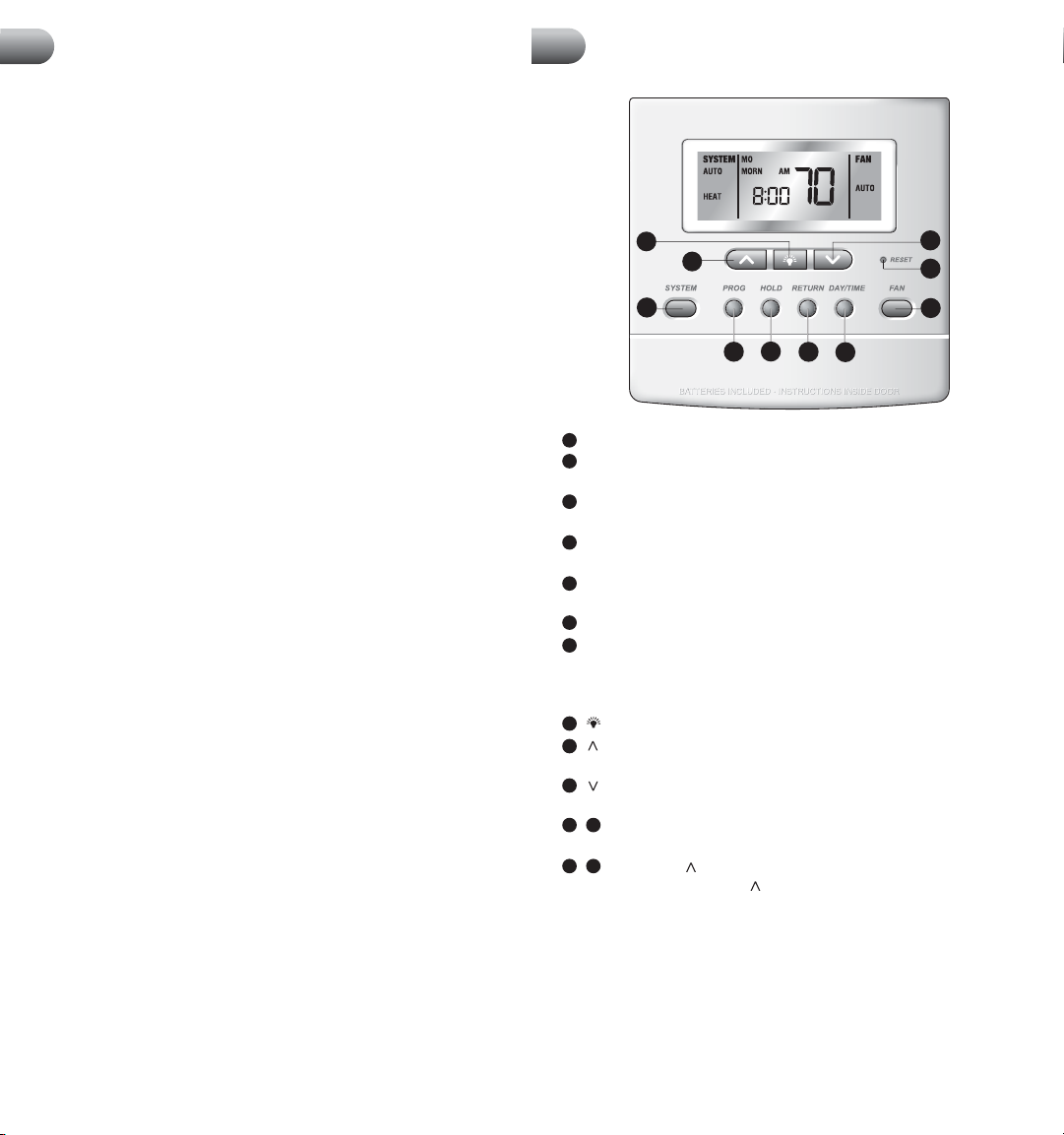
Quick Reference
Inside of model 5300 shown
8
9
1
3
2
1
SYSTEM Button: Selects AUTO (Heat/Cool), COOL, OFF, HEAT or EMER.
2
PROG Button: Program setup mode, selects set point time, temperature
and fan setting for each program.
3
HOLD Button: Enables extended hold, clears extended hold or
temporary override.
4
RETURN Button: Scrolls between installer setup screens, or returns unit
to the normal mode from program mode.
5
DAY/TIME Button: Selects hour, minute and day setting. Selects program
day in program setting mode.
6
FAN Button:
7
RESET Button: Located on front of thermostat, will return programming,
clock, differential settings, filter check monitor, adjustment limit from set
point, keypad lock, temperature hold, short cycle timer and recirculating fan
to default settings if previously programmed.
8
Button: Turns on backlight for 10 seconds.
9
Button: Increases setting (time, temperature, etc.). Scrolls between
option settings.
10
Button: Decreases setting (time, temperature, etc.). Scrolls between
option settings.
+
4 2
RETURN and PROG Buttons: When pressed at the same time, returns
unit to the normal mode from Installer setup option mode.
+
4 9
RETURN and Buttons: Installer setup option mode is entered when
holding the RETURN and buttons together for 3 seconds.
CLEAR Button: Located on back side of circuit board, resets thermostat
to all factory defaults.
Selects AUTO, ON, CIRC (recirculate) and PROG (program) modes.
4
5
10
7
6
2 3
4
Programming Installer Settings
Default Thermostat Settings
At initial power up or after Installer CLEAR is pressed, the thermostat is reset to
factory defaults. Installer CLEAR is located on the circuit board.
Function Status after Clear
Operation mode OFF, Auto Changeover enabled
Temperature hold Permanent and temporary hold cleared
Fan Switch AUTO
Clock 12:00 pm, Monday
Room temperature display 70° F (21.0° C), to be renewed within
5 seconds
Set point temperature 62° F (17.0° C) for Heat, Emergency
Heat and Off 83° F (28.0° C) for Cool
Temperature scale Fahrenheit
Operating program DAY program, Monday
Low-battery warning Off, to be renewed within 5 seconds
AC interrupted warning Off, to be renewed within 5 seconds
1st stage differential .5° F (0.2° C)
2nd stage differential 2° F (1.0° C)
Programming 7 Day, 4 Event
Deadband 3° F
Residual Cooling Fan Delay 60 seconds
Short cycle protection timer On, 5 minutes, Reset
Adaptive Recovery Mode ON
Output relays All turned off
Recirculating Fan Timer reset, with 24 min OFF, 12 min ON,
Lock OFF
Extended Hold Long (indefinite)
Filter Check Monitor 0 days-No Warning, Timer reset
Keypad Lock Complete (level 2), unlocked,
555 universal code
System type Conventional, Single Stage
1st Stage Heat Fan Control Gas
2nd Stage Heat Fan Control Electric
Fossil Fuel Compressor Lock Off
Auto Changeover Enabled
Compressor Outage Protection Off, Timer reset
Temperature Sensor Internal
12 / 24 Hour Clock 12 hour
Adjustment Limit from Set point
AC Interrupt Warning Mode OFF
User Profile Residential
0, OFF
4
Programming Installer Settings
co nt.
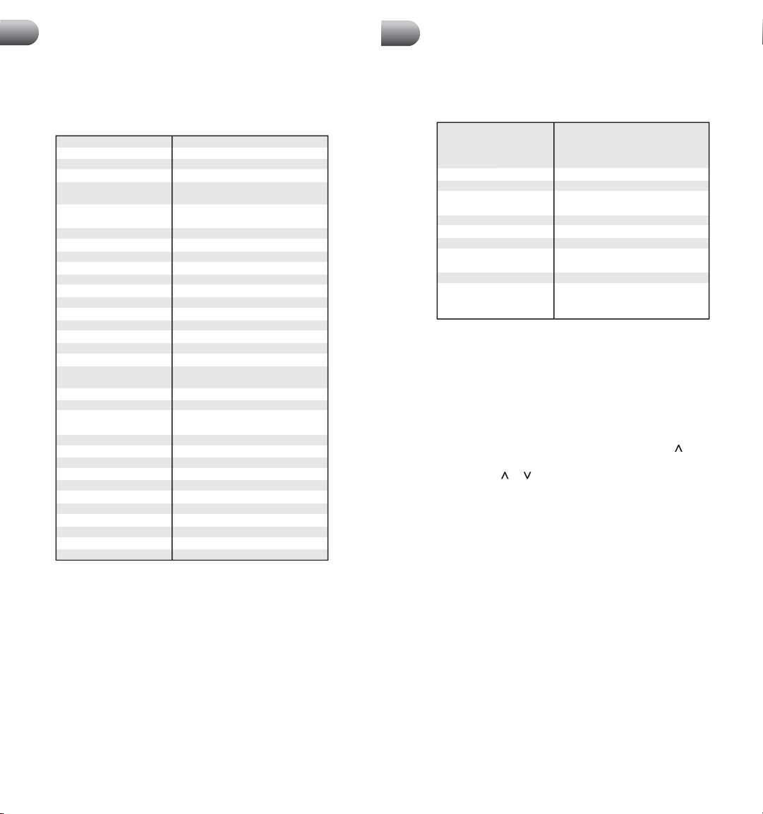
When the User RESET button (on front of thermostat) is pressed, the following
options will reset to the factory defaults. All other settings are saved when the
RESET button is pressed.
Function Status after Reset
Programming Default setting depending on
programming mode setting (see User
Manual). For manual mode: Heat - 62° F,
Cool - 83° F.
Clock 12:00 pm, Monday
1st stage differential .5° F (0.2° C)
2nd stage differential 2° F (1.0° C)
(if configured for Multi-Stage)
Filter Check Monitor 0 days-No Warning
Adjustment Limit from Set point
Keypad Lock 555 universal code or last code entered
Temperature Hold Permanent and temporary hold cleared,
reset to Long Hold
Short Cycle Timer Reset
Recirculating Fan Timer reset, 24 minute off cycle.
With recirculating lock set, fan state
defaults to CIRC.
0, OFF
Setting Thermostat Installer Options
The Installer Options section allows the system and programming parameters
to be set up at installation. The Installer Options mode is menu driven. As the
different options are programmed you may eliminate specific options. For example,
if the system is set to single stage heat pump, Option 8, selecting the first stage
fan control will no longer be available.
The Installer Option mode is entered by holding the RETURN and buttons
together for 3 seconds. Installer Option 1 Residential or Commercial will be
displayed. Pressing the or buttons will scroll between choices. To scroll to
the next installer option, press the RETURN button. The thermostat will return to
normal operating mode after the last Installer Option mode has been set or by
pressing the RETURN and PROG buttons at the same time.
NOTE: The thermostat will return to normal operating mode automatically after
30 seconds if no key is pressed.
4
Any changes to Installer Option 7 (System Type) will cause Options 8, 9, 10,
NOTE:
11 and 12 to reset to the default values that are dependent on system selection.
5
 Loading...