

MODEL 169000
AIR FILTER GAUGE
Indoor Air Quality Products
INSTALLATION INSTRUCTIONS
AIR FILTER GAUGE
INSTALL CLEAN
FIL TER , R UN
BLOWER AND
ADJUST GAUGE
UP
POINTER TO
CLEAR AREA
IN CE NTE R
OF GR EEN
DOWN
R
E
T
L
I
F
E
G
N
A
H
C
N
A
E
L
C
S
I
R
E
T
L
I
F
APPLICATION
The 169000 Air Filter Gauge provides a visual indication of the need to replace the air filters in forced air heating and cooling
systems. The gauge is installed between the blower and the filter where a slight vacuum exists due to the air flow resistance
of the air filter. Air flowing into the gauge, around the calibration screw, lifts a vane in proportion to the negative pressure in
the blower compartment. As the air filter loads, the vacuum increases, raising the vane to indicate a filter change
is necessary.
The gauge may be calibrated in a negative pressure range from 0.1 to 0.4 inch w.c. When properly calibrated in this range a
vacuum increase of 0.10 to 0.15 inch w.c. will indicate a filter change is necessary.
PRECAUTIONS
The installer should be an experienced service technician. When drilling the hole
in the blower compartment extreme care should be taken not to damage
components within the heating or cooling system.
RETURN
AIR
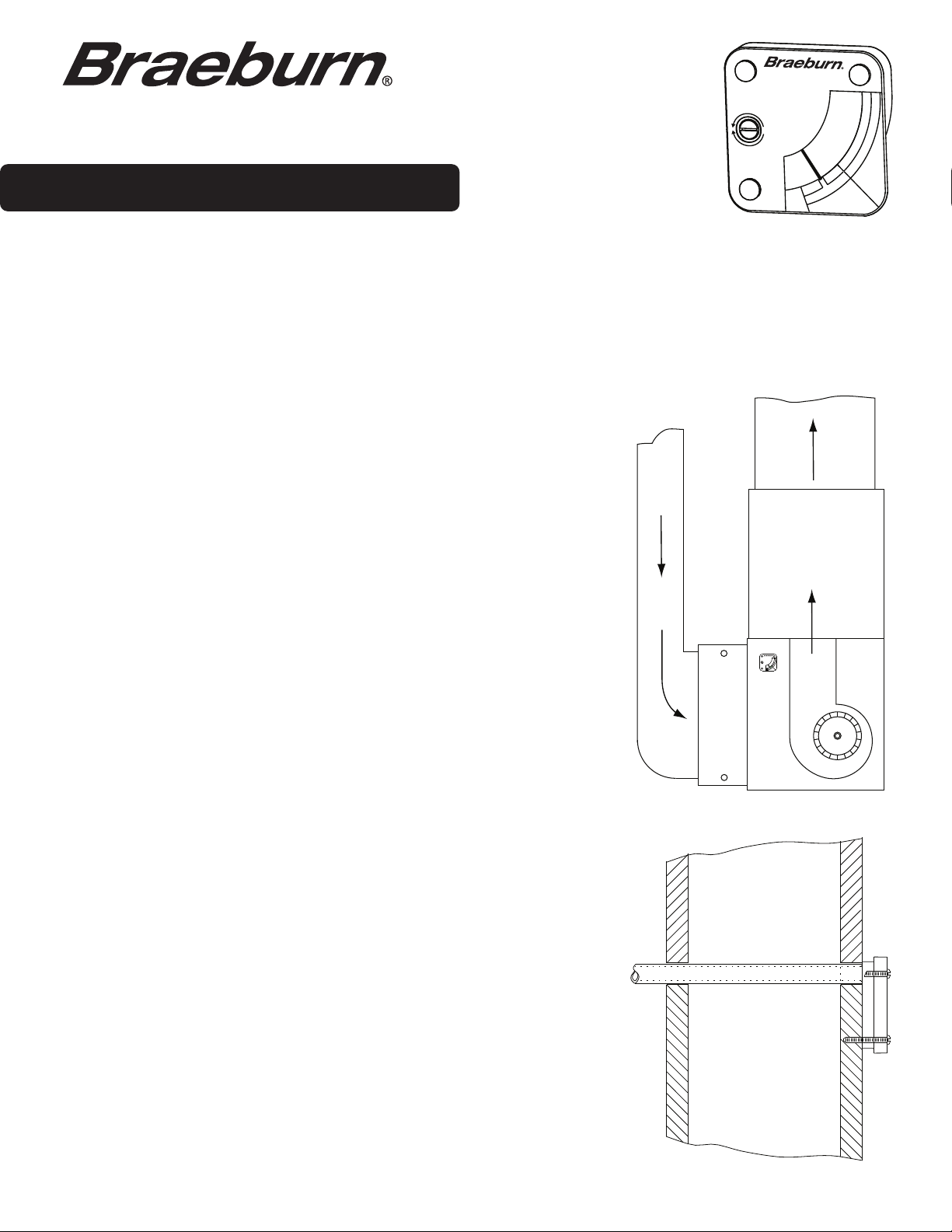
INSTALLATION
1.
The gauge must be located where it can sense pressure conditions in the
(Figure 1)
blower compartment between the filter and the blower. Select a location on
a
vertical surface enclosing the blower compartment and drill a 3/8" hole.
2. Remove the protective paper from the foam adhesive strip on the back
of the gauge.
3. Mount the gauge in a level position with the pressure sensing tube
projecting into the blower compartment.
4. See “CALIBRATION”.
OPTIONAL REMOTE INSTALLATION
(Figure 2)
FIELD SUPPLIED: One (1) piece of 5/16” (inside diameter) vinyl tubing up to 10
feet in
1.
Select a location on the blower compartment between the air filter and the
length, and three (3) #4-24 x 1” screws.
blower and drill a 7/16" diameter hole. Insert one end of the vinyl tubing
about 2" into the hole.
2.
On a wall, enclosing the furnace room for example, mark a position where
the filter gauge can be easily seen and is within reach of the vinyl tube.
3.
Drill a 1/2" diameter hole through the wall and feed the vinyl tube through
the
hole. Keep overall length of tubing used as short as possible.
GAUGE
AIR FILTER GAGE
INSTALL CLEAN
FILTER, RUN
BLOWER AND
ADJUST GAGE
UP
POINTER TO
R
CLEAR AREA
E
IN CENTER
T
OF GREEN
L
I
F
E
G
N
A
DOWN
H
C
N
A
E
L
C
S
I
R
E
T
L
I
F
AIR
FILTER
BLOWER
Figure 1
4.
Push the three plastic retainer clips out from the back of the gauge with a
blunt tool. They will be replaced with the three #4-24 x 1" screws included.
5.
Push the vinyl tubing over the pressure sensing tube of the gauge and
move the gauge back against the wall in a level position. Drill three 3/32"
diameter holes through the gauge holes. Drive the three screws to hold the
gauge in place
. Do not overtighten.
6. See “CALIBRATION”.
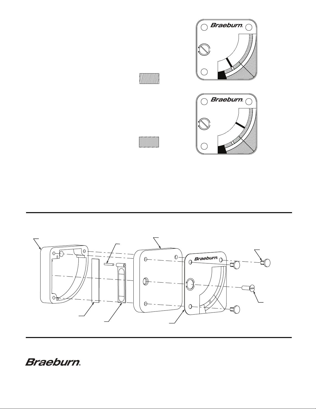
Figure 2
CALIBRATION
Install a clean filter and run blower on highest speed.
With a small screwdriver adjust the calibration screw, on
the face of the gauge, to put the pointer in the clear area
in the center of the green "FILTER IS CLEAN" range.
GREEN
OPERATION
AIR FILTER GAUGE
INSTALL CLEAN
FI LTER , R UN
UP
BLOWER AN D
ADJUST GAUGE
POINTER TO
CLEAR AREA
IN CE NTE R
OF GR EEN
DOWN
U.S.
PAT.
6190442
R
E
T
L
I
F
E
G
N
A
H
C
N
A
E
L
C
S
I
R
E
T
L
I
F
As the air filter begins to clog the pointer will move up
in the gauge. When the pointer moves into the red
"CHANGE FILTER" range a clean filter should be
installed.
RED
AIR FILTER GAUGE
INSTALL CLEAN
FI LTER , R UN
UP
BLOWER AN D
ADJUST GAUGE
POINTER TO
CLEAR AREA
IN CE NTE R
OF GR EEN
DOWN
U.S.
PAT.
6190442
R
E
T
L
I
F
E
G
N
A
H
C
N
A
E
L
C
S
I
R
E
T
L
I
F
SERVICE
The gauge may be disassembled for service although this should rarely be required since it contains a small filter
screen to stop dust from entering the area of the vane. Remove gauge and, from the back, push white plastic
clips out with a blunt tool. Remove calibration screw, lift off clear cover and dust all parts with a clean brush.
Reassemble and test that the vane moves freely in the gauge. A fresh adhesive strip may be required to reinstall.
U.S. PAT. 6190442
EXPLODED VIEW
GAUGE HOUSING
PIN
GAUGE COVER
RETAINER CLIP
FILTER SCREEN
VANE
Braeburn Systems LLC
2215 Cornell Avenue • Montgomery, IL 60538
Technical Assistance: www.braeburnonline.com
Call us toll-free: 866-268-5599 (U.S.)
630-844-1968 (Outside the U.S.)
©2010 Braeburn Systems LLC • All Rights Reserved • 169000-100-001
DIAL PLATE
AIR FILTER GAUGE
UP
DOWN
INSTALL CLEAN
FILTER, RUN
BLOWER AND
ADJUST GAUGE
POINTER TO
CLEAR AREA
IN CENTER
OF GREEN
R
E
T
L
I
F
E
G
N
A
H
C
N
A
E
L
C
S
I
R
E
T
L
I
F
CALIBRATION
SCREW
FOAM ADHESIVE STRIP - NOT SHOWN
 Loading...