

®
140424
2 Zone
Expander Panel
For Use with Braeburn
Model 140404
Store this manual for future reference.
Installer Manual
Warning
Caution
Can cause electrical shock or equipment damage. Always turn off power to the heating/air
conditioning system prior to installing or adjusting the Zone Panel Expander. Complete the
wiring for the main panel and expansion panel before applying transformer power.
This panel is designed for professional installation, and is to be installed and configured as
described in this manual. Any other use is not recommended and will void the warranty.
Install disconnect and overload protection on circuits as required by code authorities having
jurisdiction for the installation.
Read all of the instructions before proceeding
Voltage Hazard
140424-100-02
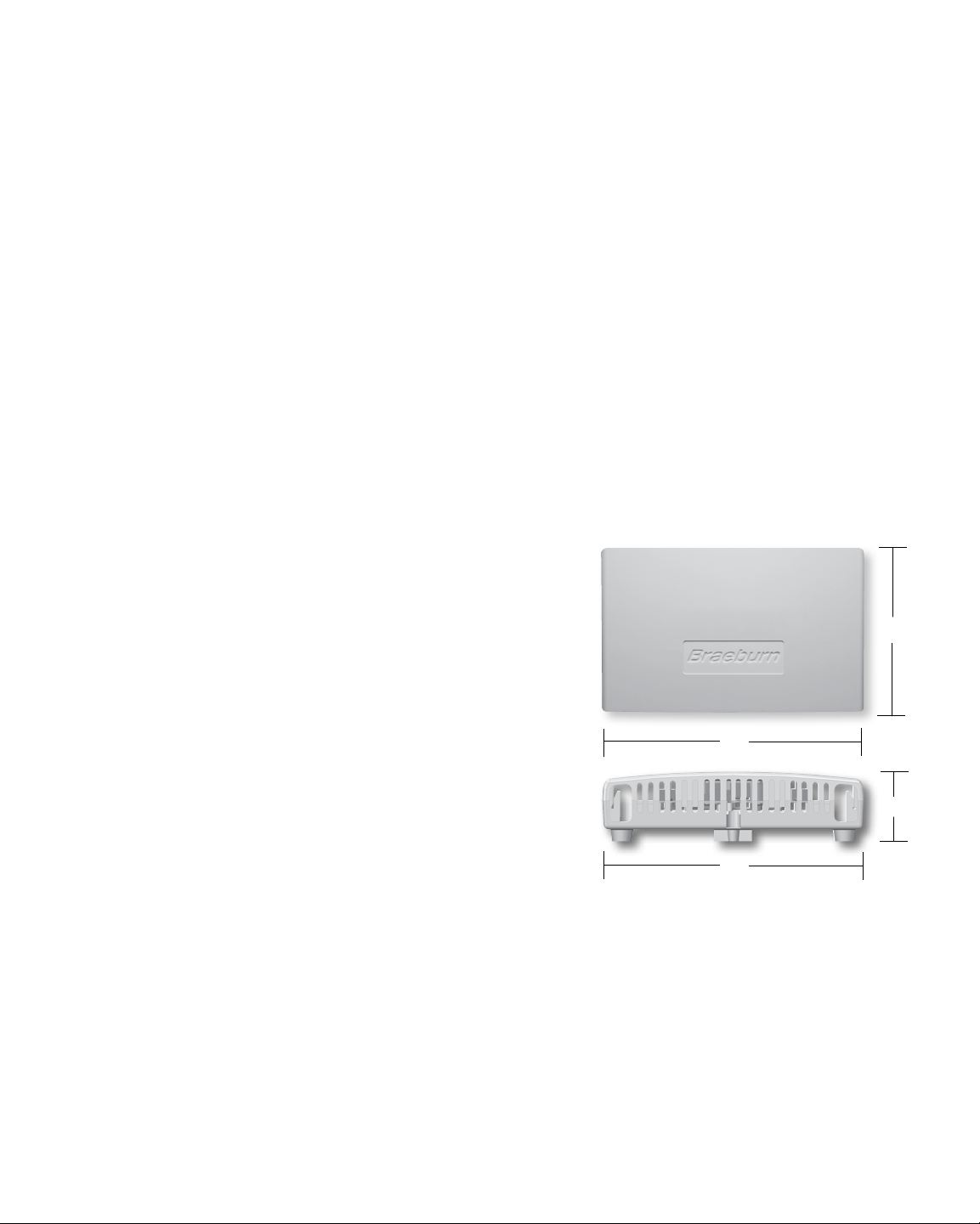
Table of Contents
1
Specifications.....................................................................................................................2
2
Suitable Mounting Locations...............................................................................................3
3
Wiring Diagrams............................................................................................................ 5-9
4
Zone Addressing.................................................................................................................9
5
Adding Zones to Main Panel..............................................................................................10
6 Operation...............................................................................................................................10
7
Error Conditions................................................................................................................ 11
8
Warranty........................................................................................................................... 1
Figure 1
Specifications
1
2
Storage temperature:
-40˚–167˚F (-40˚–75˚C)
Operating temperature:
-22˚–167˚F (-30˚–75˚C)
Voltage:
24 VAC, Nominal 60Hz
18-30 VAC Maximum
Operating humidity:
5–95% RH
Panel Power:
4 VA @ 24 VAC
Current Draw Max:
75 VA @ 24 VAC
Current Draw Per Zone:
50 VA Max
Protection:
Electronic self resetting current
limiting for panel power and
damper zones
Configuration:
Zone number by switch setting
Maximum Zones:
2 Zones Per Expander Panel
Up to a Maximum of 14 Two Zone
Expanders = 32 Total
Zones (28 Expander Zones,
4 Main Panel Zones)
Dimensions:
See Figure 1
5.1”
8”
2.1”
8”
2
2
Suitable Mounting Locations
Mount the Zone Panel Expander near the Main Panel. If desired, the expander panel can be mounted up to
500 feet from the main panel. The panel can be mounted in any orientation on a wall, stud, roof truss, or the
return-air plenum. For appearance, mount the panel near the main panel for easy panel to panel wiring.
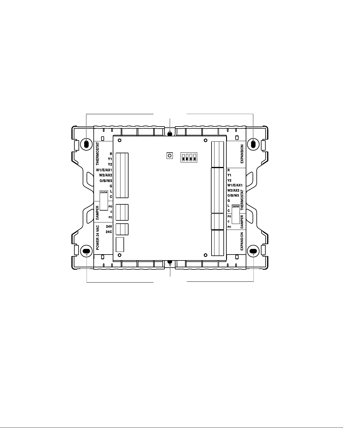
Remove the panel cover and use the base as a template to drill mounting holes (see Figure 2). Attach the
panel with appropriate screws. Use mounting anchors as needed for drywall or plaster installations.
drill holes
COM1
COM2
GND
COM3
COM4
drill holes
Figure 2
COM1
COM2
GND
COM3
COM4
3

3
Wiring the Panel
Always turn off power to the heating/air conditioning system prior to installing or adjusting the Zone Panel
Expander. Use the following general wiring instructions for all systems. Specific wiring will vary depending on
the type of thermostats and dampers used for the installation. NOTE: Up to 2 wires can be inserted into each
terminal position. To release wires, press down on top of wiring terminal and gently pull out wire(s).
COM1
COM2
GND
COM3
COM4
4
3
4
2
COM1
COM2
1
7 5
Figure 3
6
GND
COM3
COM4
2
3
4

ZONE PANEL EXPANDER WIRING TERMINALS
Terminal
PANEL 24V 1 INPUT 24 VAC Transformer Power 75 VA Maximum
POWER 24C 1 INPUT 24 VAC Transformer Common
DAMPERS PO 2 OUTPUT 24 VAC Power Open Zone Damper Terminal
C 2 OUTPUT Zone Damper Common Terminal
PC 2 OUTPUT 24 VAC Power Close Zone Damper Terminal
EXPANSION COM1 2 OUTPUT Expander Panel Communication
COM2 2 OUTPUT Expander Panel Communication
GND 2 INPUT Expander Panel Communication Ground
COM3 2 INPUT Expander Panel Communication
COM4 2 INPUT Expander Panel Communication
THERMOSTAT R 2 OUTPUT 24 VAC Thermostat Power
Y1 2 INPUT 1st Stage Compressor Call
Y2 2 INPUT 2nd Stage Compressor Call
W1/E/AX1 2 INPUT [W1] 1st Stage Conventional Heat Call [E] Emergency Heat Call
[AX1] 1st Stage Auxiliary Heat Call
W2/AX2 2 INPUT [W2] 2nd Stage Conventional Heat Call [AX2] 2nd Stage Auxiliary Heat Call
O/B/W3 2 INPUT [O] Cool Active Reversing Valve Call [B] Heat Active Reversing Valve Call
[W3] 3rd Stage Conventional Heat Call
G 2 INPUT Fan Call
L 2 OUTPUT System Malfunction Indicator
C 2 OUTPUT 24 VAC Transformer Common
RESET BUTTON Press once to restart panel
Hold for 5 seconds to reset panel and reset all factory defaults.
ZONE ADDRESS DIP SWITCHES See Zone Addressing (section 4)
WIRE STRIP GUIDE Wires should be stripped 3/8 inch minimum.
1
2
3
4
5
6
7
Qty.
Function Description
The expansion zones may be wired to either the top or bottom communication terminals on the main panel
or to the top or bottom communication terminals on the expansion panel. This wiring flexibility allows the
installer to choose the most flexible, cost effective wiring for the installation.
Each expansion panel must have a 5 Wire connection for proper communication. It is not necessary to use
shielded wire for the panel to panel connection. 18 - 20 Gauge solid thermostat wire or similar is acceptable.
When wiring the expansion panels be sure to connect the terminals from one panel to the next using the
following terminal connections.
MAIN Panel to Expander
Main Panel to Expansion Panel
COM1 COM1
COM2 COM2
GND GND
COM3 COM3
COM4 COM4
Expansion Panel to Expansion Panel
COM1 COM1
COM2 COM2
GND GND
COM3 COM3
COM4 COM4
Expander to Expander
5

Example Wiring Options
Daisy Chain All Zones
Located at Main Panel
Main Panel
Expander Panel
Zones 5-6
Expander Panel
Zones 7-8
Expander Panel
As Needed
Daisy Chain Zones Located Remote
to Main Panel (Up to 500 Feet)
Star Wiring All Zones
Located at Main Panel
Expander Panel
Zones 7-8
Main Panel
Expander Panel
Zones 5-6
Daisy Chain Zones Located Remote to Main Panel -
Expander Panel
As Needed
Expander Panel
As Needed
Remote Panels Wired in Star Configuration
Main Panel
500 Ft. (Maximum)
Expander Panel
Zones 5-6
Expander Panel
Zones 7-8
Expander Panel
As Needed
Main Panel
500 Ft. (Maximum)
Expander Panel
Zones 5-6
Expander Panel
As Needed
Expander Panel
As Needed
Expander Panel
As Needed
NOTE: To prevent possible interference do not run low voltage
wiring along side 120 VAC wiring or magnetic ballasts.
6

3.1
Damper Wiring
Install the system dampers using the instructions provided by the manufacturer.
Connect the dampers to the zone panel expander as shown for either a 2-wire
or 3-wire damper. The sum of all dampers powered by the zone panel should
not exceed 75 VA at 24 VAC. Use a slave relay if additional damper power
is required.
ALWAYS PROVIDE DISCONNECT AND OVERLOAD PROTECTION AS REQUIRED
PO
COM
PC
Zone Panel 2-Wire Damper
PO
COM
PC
Zone Panel 3-Wire Damper
M
M
PO
C
PC
3.2
CONVENTIONAL THERMOSTATS
1 HEAT / 1 COOL
R
W1 Heat Call
Y1 Cooling Call
G Fan Call
C 24 VAC Transformer Common
[Note 1]
24 VAC Power
NOTES
[1] Wiring to the C terminal is required only for thermostat power.
Thermostat Wiring
2 HEAT / 2 COOL
R
W1 Heat Call Stage 1
W2 Heat Call Stage 2
Y1 Cooling Call Stage 1
Y2 Cooling Call Stage 2
G Fan Call
C 24 VAC Transformer Common
[Note 1]
24 VAC Power
3 HEAT / 2 COOL
R
W1 Heat Call Stage 1
W2 Heat Call Stage 2
W3 Heat Call Stage 3
Y1 Cooling Call Stage 1
Y2 Cooling Call Stage 2
G Fan Call
C 24 VAC Transformer Common
[Note 1]
24 VAC Power
7

HEAT PUMP THERMOSTATS
1 HEAT / 1 COOL -
R
O/B Changeover Valve [Note 2]
Y1 Compressor Call (1st Stage Heating/Cooling)
G Fan Call
C 24 VAC Transformer Common [Note 1]
24 VAC Power
No Auxiliary Heat
2 HEAT / 2 COOL - No Auxiliary Heat
R
O/B Changeover Valve [Note 2]
L Optional System Fault Monitor
Y1
Y2
G Fan Call
C 24 VAC Transformer Common [Note 1]
24 VAC Power
Compressor Call Stage 1 (1st Stage Heating/Cooling)
Compressor Call Stage 2 (2nd Stage Heating/Cooling)
2 HEAT / 1 COOL - With Auxiliary Heat
R
O/B Changeover Valve [Note 2]
L Optional System Fault Monitor
W2 Auxiliary Heat Relay (2nd Stage Heating)
Y1 Compressor Call (1st Stage Heating/Cooling)
E Emergency Heat Call
G Fan Call
C 24 VAC Transformer Common [Note 1]
24 VAC Power
3 HEAT / 2 COOL - With Auxiliary Heat
R
O/B Changeover Valve [Note 2]
L Optional System Fault Monitor
AX1 Auxiliary Heat Relay (3rd Stage Heating)
Y1 Compressor Call (1st Stage Heating/Cooling)
Y2 Compressor Call (2nd Stage Heating/Cooling)
E Emergency Heat Call
G Fan Call
C 24 VAC Transformer Common [Note 1]
24 VAC Power
4 HEAT / 2 COOL - With Auxiliary Heat
R
O/B Changeover Valve [Note 2]
L Optional System Fault Monitor
AX1 Auxiliary Heat Relay (3rd Stage Heating)
AX2 Auxiliary Heat Relay (4th Stage Heating)
Y1 Compressor Call (1st Stage Heating/Cooling)
Y2 Compressor Call (2nd Stage Heating/Cooling)
E Emergency Heat Call
G Fan Call
C 24 VAC Transformer Common [Note 1]
NOTES
[1] Wiring to the C terminal is required only for thermostat power.
[2] O (Cool active) or B (Heat active) must match the zone panel
installer settings.
24 VAC Power
8

3.3
Transformer Wiring
Install the transformer using the instructions provided by the manufacturer. Size
the transformer to the damper requirements. The zone panel has a built-in, selfresetting fuse. The maximum damper power per zone is 75 VA at 24 VAC. Connect
the transformer to the zone panel as shown. NOTE: Additional dampers or
dampers with a higher current draw will require the use of a separate slave relay.
ALWAYS PROVIDE DISCONNECT AND OVERLOAD PROTECTION AS REQUIRED
4
Use the following instructions to identify the zones on the zone panel expander.
No other configuration is necessary on the zone panel expander. Carefully slide
the dip switches to match the new zone numbers.
Use the open area provided on the expander panel to mark the new zone
numbers. When setting the switches to identify the expander panel, use a pen
or small screwdriver. Do not use a pencil, which may contain conductive material
in the writing point.
Zone Addressing
Switch Position
HOT
CC
Dedicated
Zoning Transformer
O
1 2 3 4
N
Example Switch Position
for Zones 15 and 16
Zone
Panel
24V
24C
Zone ID 1 2 3 4
5 and 6 OFF OFF OFF OFF
7 and 8 ON OFF OFF OFF
9 and 10 OFF ON OFF OFF
11 and 12 OFF OFF ON OFF
13 and 14 OFF OFF OFF ON
15 and 16 ON ON OFF OFF
17 and 18 ON OFF ON OFF
19 and 20 ON OFF OFF ON
21 and 22 OFF ON ON OFF
23 and 24 OFF ON OFF ON
25 and 26 OFF OFF ON ON
27 and 28 ON ON OFF OFF
29 and 30 ON ON OFF ON
31 and 32 ON OFF ON ON
9

5
The 4 Zone Expandable Panel can be expanded to up to 32 zones with four zones on the main panel and 28
total expansion zones. Additional zones must have power and communication wires to be recognized and
controlled by the main expandable panel. To add additional zones, complete all wiring and start the main
panel test mode.
Start the panel test mode to add additional zones:
1. Ensure all wiring is complete, zone addresses are set (section 4),
and power has been applied to the main and expansion panels.
2. Press TEST for 3 seconds and release.
3. Press and release SELECT once for each new zone added.
New zones must be added in blocks of two. NOTE: After second
new zone is added, expander LED will change from red to green,
and ZONE OK will appear in the main panel display.
4. If new zones do not appear, check wiring and ensure expansion
zones have power.
5. Press HOLD FOR EXIT for 3 seconds to complete adding zones.
Add Zones to Main Panel
6
The Zone Panel Expander has built in LED’s to tell the installer and the system owner the current operating
mode of the panel. Refer to the figure below and the following descriptions of the panel LED’s for operation
information.
Operation
LED COLOR INDICATION
Panel Status LED
Panel Power Red
Green Flashing Green when in normal operation
Thermostat LED’s (2 Positions)
R Red 24 VAC
Y1 Yellow
Y2 Yellow
W1/E/AX1 White
W2/AX2
O/B/W3
G Green
L Yellow
Damper LED’s (2 Positions)
Power Close / Power Open Red / Green Red On Damper Closed; Green on Damper Open
No light when wiring short detected.
White
Yellow
Flashing Red until communication is good
available to Thermostat
Thermostat First Stage Compressor Call
Thermostat Second Stage Compressor Call
Thermostat Call for W1 or E or AX1
Thermostat Call for W2 or AX2
Thermostat Call for O, B or W3
Thermostat Fan Call
System Check Signal to Thermostat Active
10

7
The Main Panel continually monitors various components of the zone system and will display a message
when the following Expander Panel monitored conditions are detected.
Invalid Address on Expansion Panel
Displayed when an invalid address has been set on an expansion
panel. This message will appear when an expander is powered
up and wired to the communication terminals. To locate the
expander panel with the invalid address, view the expander
panel status LED. The status LED will be flashing red.
Duplicate Address on Expansion Panel
Displayed when a duplicate address has been set on an expansion
panel. This message will appear when an expander is powered up
and wired to the communication terminals. To locate the expander
panel with the duplicate, view the expander panel status LED.
The status LED will be flashing red. Change the expander
switches as noted in section 4 to remove duplicate addresses.
Error Conditions
11

®
Limited Warranty
When installed by a professional contractor, this product is backed by a 5 year limited warranty. Limitations apply.
For limitations, terms and conditions, you may obtain a full copy of this warranty:
· Visit us online: www.braeburnonline.com/warranty
· Phone us: 866.268.5599
· Write us: Braeburn Systems LLC
2215 Cornell Avenue
Montgomery, IL 60538
Store this manual for future reference.
5
YEAR
LIMITED
WARRANT
Y
®
Braeburn Systems LLC
2215 Cornell Avenue • Montgomery, IL 60538
Technical Assistance: www.braeburnonline.com
Call us toll-free: 866-268-5599 (U.S.)
630-844-1968 (Outside the U.S.)
©2014 Braeburn Systems LLC • All Rights Reserved • Made in China.
12
140424-100-02
 Loading...